2. Odd Form Definition
• Odd Component:
• Odd shape through-hole components
that cannot be automatically placed
using standard through-hole insert
machines due to the component’s
height, shape or weight.
Odd Component Examples
3. Odd Form Trends
– Drive to reduce defects
– Increase throughput
– Cost/availability of manual labor
– Packages becoming available
– Reduce cost of manufacturing
4. Market Focus – Odd Form AssemblyMarket Focus – Odd Form Assembly
• Odd form factor component handling for PCB
assembly
– Market Challenges
• Irregular packaging
• Conversion from Hand assembly
• Competing in low cost markets
• No industry standards governing assembly process
• Large / heavy components
• High force requirements
– S7000 Advantage
• Most flexible head available on the market
• Vision component inspection enables use in Pin in
Paste applications
• Vision component inspection finds quality problems
before insertion
• Data driven programming and component database
bridges the gap between custom automation and
Surface Mount assembly machines
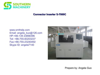
5. Connector Inserter S-7000C
Single Head to Four Head (Optional)
Insertion speeds up to 8,000/hour
Lowest cost of ownership in the industry
Through Hole Products
6. •
Connector InserterConnector Inserter S-7000CS-7000C - In Detail- In Detail
-Highest Throughput
•8,000 CPH Spec Speed
-Insertion Head
• Single Head to Four Head (Optional)
- Lowers Cost of Ownership
• Low Energy costs. Power supply: 2.0KVA
• Minimal preventative maintenance required.
RMB2,000/Month/Unit
- Easy to Use User Interface
• Easy operation, use Excel program and USB input.
• Off-line programming available
• Components available: Connector, Max. length is 20mm, Max.
Width is 13mm, Max. Height is 26mm.
7. Connector InserterConnector Inserter S-7000CS-7000C
1 Insertion rate 8,000PCS / H
2 Package Types Bulk Connector
3 PCB Size (Min)50 mm x50mm、(Max)480mm x 390mm
4 Components available
Connector, Max. Length: 20mm; Max. Width: 13mm;
Max. Height: 26mm
5 Insert Head
1 to 4 pcs Heads; Insert different types Connector at
same time
6 Insert Direction 0-90° , integral multiple of 1° .
7 Component require Pin Lead thickness≤ 0.8mm
8 Component Body distance Component and Component distance is 1mm
9
Component direction
detection
Vibration Feeder detection the material
10 Component Fixed Mode Outlet Clinch 2pcs Lead
11 Control System Industrial PC
12 Display System 17’’ LCD
13 Machine Size (L × W × H) 2160mm× 1330mm× 1530mm
14 Machine Weight 1200KG
15 Power supply 220V, AC (single phase) 50/60 HZ, 2KVA;
16 System Protection UPS, keep machine run 15 minutes without power
17 Working Power 800W (Energy-saving)
18 Air pressure 5-6kg/CM2
19 Air consumption 0.6 m3
/minute
20 Coordinate correction
Machine vision systems, multi-point MARK vision
correction.
21 Driving system AC Servo、 AC motors
22 Data input USB interface input (EXCEL format)
23 Control System
English version interface (WINDOWS system control
platform)LCD monitor
24 PCB transfer mode Manual /Automatic optional
Specification Parameter