The document provides background information on docking procedures used between the Space Shuttle and the International Space Station. It describes the steps taken as the Space Shuttle approaches and docks with the station, including using reaction control systems to change speed and position at distances of 110 meters, 50 meters, and 9 meters from the station. It also lists Newton's Three Laws of Motion, which govern the motion of objects in space. The objectives are for students to demonstrate and identify docking procedures and Newton's Laws of Motion through a hands-on docking activity using templates, string, and other materials.
Warp Drive: Frequency Modulation (FM) of Electromagnetic LightNorman Imperial
Frequency Modulation (FM) of electromagnetic light is the first step towards manipulated light (warp drive).
The extraterrestrials are able to rapidly traverse the spans of space that exist between the stars. The spacecraft they employ to accomplish their interstellar flights can carry a number of the smaller interplanetary craft described in the previous section. The interstellar vehicles can accurately be called "motherships". These cigar shaped craft, ranging from 1/4 to 1&1/2 miles in length utilize a totally different type of propulsion system, called the "eggbeater drive" because of the shape of the wake of energy emitted from its propulsion system. The basis of this new type of propulsion is called manipulated light.
Article by Ken Kremer
he Mars 2020 Perseverance mission is NASA’s next mission to Mars as well as
being the most complex and scientifically advanced robotic mission sent to
the Red Planet.
The $2.4 Billion Mars Perseverance rover is a flagship mission dedicated to the
search for signs of life beyond Earth, as part of NASA’s Mars Exploration Program,
a long-term effort of robotic exploration of the Red Planet.
The Perseverance Mars 2020 mission will search for signs of ancient microbial life,
characterize Mars’ climate and geology, collect carefully selected samples for
future return to Earth, and pave the way for human exploration of the Red Planet
as soon as the 2030s.
Perseverance will also ferry a separate technology experiment to the surface of
Mars — a helicopter named Ingenuity, the first aircraft to fly in a controlled way
on another planet.
Launch is now targeted for a launch opportunity in the July/August timeframe
when Earth and Mars are aligned in good positions relative to each other for
landing on Mars.
The car-sized Perseverance Mars 2020 rover is targeted for liftoff on NET 30 July
2020 aboard a United Launch Alliance (ULA) Atlas V 541 rocket from Space
Launch Complex 41 on Cape Canaveral Air Force Station, Florida.
The approximately month-long launch window for the Mars 2020 Perseverance
rover mission currently extends until August 15.
Jupiter’s magnetosphere and aurorae observed by the Juno spacecraft during it...Sérgio Sacani
The Juno spacecraft acquired direct observations of the jovian magnetosphere and auroral
emissions from a vantage point above the poles. Juno’s capture orbit spanned the jovian
magnetosphere from bow shock to the planet, providing magnetic field, charged particle,
and wave phenomena context for Juno’s passage over the poles and traverse of Jupiter’s
hazardous inner radiation belts. Juno’s energetic particle and plasma detectors measured
electrons precipitating in the polar regions, exciting intense aurorae, observed
simultaneously by the ultraviolet and infrared imaging spectrographs. Juno transited
beneath the most intense parts of the radiation belts, passed about 4000 kilometers
above the cloud tops at closest approach, well inside the jovian rings, and recorded the
electrical signatures of high-velocity impacts with small particles as it traversed the equator.
Jupiter’s interior and deep atmosphere: The initial pole-to-pole passes with ...Sérgio Sacani
On 27 August 2016, the Juno spacecraft acquired science observations of Jupiter,
passing less than 5000 kilometers above the equatorial cloud tops. Images of Jupiter’s
poles show a chaotic scene, unlike Saturn’s poles. Microwave sounding reveals weather
features at pressures deeper than 100 bars, dominated by an ammonia-rich, narrow
low-latitude plume resembling a deeper, wider version of Earth’s Hadley cell. Near-infrared
mapping reveals the relative humidity within prominent downwelling regions. Juno’s
measured gravity field differs substantially from the last available estimate and is one
order of magnitude more precise. This has implications for the distribution of heavy
elements in the interior, including the existence and mass of Jupiter’s core. The observed
magnetic field exhibits smaller spatial variations than expected, indicative of a rich
harmonic content.
Ultrafast transfer of low-mass payloads to Mars and beyond using aerographite...Sérgio Sacani
With interstellar mission concepts now being under study by various space agencies and institutions,
a feasible and worthy interstellar precursor mission concept will be key to the success of the long
shot. Here we investigate interstellar-bound trajectories of solar sails made of the ultra lightweight
material aerographite. Due to its extremely low density (0.18 kgm−3) and high absorptivity (∼1), a
thin shell can pick up an enormous acceleration from the solar irradiation. Payloads of up to 1 kg can
be transported rapidly throughout the solar system, e.g. to Mars and beyond. Our simulations consider
various launch scenarios from a polar orbit around Earth including directly outbound launches as well
as Sun diver launches towards the Sun with subsequent outward acceleration. We use the poliastro
Python library for astrodynamic calculations. For a spacecraft with a total mass of 1 kg (including
720 g aerographite) and a cross-sectional area of 104 m2, corresponding to a shell with a radius of 56m,
we calculate the positions, velocities, and accelerations based on the combination of gravitational and
radiation forces on the sail. We find that the direct outward transfer to Mars near opposition to Earth
results in a relative velocity of 65 kms−1 with a minimum required transfer time of 26 d. Using an
inward transfer with solar sail deployment at 0.6AU from the Sun, the sail’s velocity relative to Mars
is 118 kms−1 with a transfer time of 126 d, whereMars is required to be in one of the nodes of the two
orbital planes upon sail arrival. Transfer times and relative velocities can vary substantially depending
on the constellation between Earth andMars and the requirements on the injection trajectory to the Sun
diving orbit. The direct interstellar trajectory has a final velocity of 109 kms−1. Assuming a distance
to the heliopause of 120AU, the spacecraft reaches interstellar space after 5.3 yr. When using an
initial Sun dive to 0.6AU instead, the solar sail obtains an escape velocity of 148 kms−1 from the
solar system with a transfer time of 4.2 yr to the heliopause. Values may differ depending on the
rapidity of the Sun dive and the minimum distance to the Sun. The mission concepts presented in this
paper are extensions of the 0.5 kg tip mass and 196m2 design of the successful IKAROS mission to
Venus towards an interstellar solar sail mission. They allow fast flybys atMars and into the deep solar
system. For delivery (rather than fly-by) missions of a sub-kg payload the biggest obstacle remains in
the deceleration upon arrival.
Dear Students, remember that you have to be something characterized in the life!! because you are able to do that.
{My Thanks to All of You because you helped me to show this PPT in a very famous company of Smart Boards}. You can watched in YouTube Channel!
Orbit design for exoplanet discovery spacecraft dr dora musielak 1 april 2019Dora Musielak, Ph.D.
Most exoplanets have been discovered with space telescopes. Starting with an overview of rocket propulsion, this presentation introduces spacecraft trajectories in the Sun-Earth-Moon System, focusing especially on those appropriate for exoplanet detection spacecraft. It reviews past, present, and future exoplanet discovery missions.
PHYS 220A30 November 2015Endeavour Space ShuttleThe visit .docxrandymartin91030
PHYS 220A
30 November 2015
Endeavour Space Shuttle
The visit to Endeavour Space Shuttle in Los Angeles provided me with a deeper insight of how physics principles are applied in real life. Not only did I learn of how the rockets get propelled into space, but also gained a better understanding of how the satellites are injected into orbit after the rocket gets into space. As I strolled into the facility, I was excited since I finally had the chance to get the answers to the several questions that crammed in my mind regarding rockets and satellites. Before the visit, questions such as how does the spacecraft travel with accuracy and know where it’s going? Once it reaches the orbit, what keeps it in motion? Besides, can any place be chosen for the launch of the rockets? Even more importantly, I was fascinated to learn the various structural parts of the rockets and the fuel used in its operation.
The process of rocket propulsion was illustrated to me just like I had learned in my theoretical physics. Essentially, a rocket is propelled forward due to a rearward ejection of burned fuel that was initially in the rocket. Consequently, the forward thrust gained by the rocket is as a result of the back force of the ejected burning fuel. In the end, the rocket propulsion principle confirmed Newton’s third law of motion which states that action and reaction are opposite yet equal forces. Unlike the jet engine that depends on drawing in air to burn the fuel, the rockets utilize the fuel on board which is a mixture of liquid oxygen and hydrogen to cause combustion ensuring that they can operate in space where a vacuum exists. I was also intrigued to learn that the rocket didn’t work on the principle of pushing against the ground, or air but depended solely on the thrust force provided by the burning fuel. I also realized that for a large weight of rockets is dominated by fuel. As such, for massive uplift force to be achieved by the rocket, the fuel has to be burned at a rapid rate. This would ultimately ensure that the rate of change of momentum is huge and therefore causing the propulsion force to be sufficient to cause uplift. Certainly, this principle was in line with Newton’s second law of motion which suggests that the magnitude of force on a moving body is directly proportion to the rate of change of its momentum {F = (v-u)dm/t}.
The second fact that I learned at the science facility is that the earth is shielded from radioactive particles from the sun by an electromagnetic field around it. As such, when the rockets pass through the layer of the earth’s electromagnetic field, it may get charged and risk burning when leaving or entering the earth’s atmosphere from space. Therefore, the rocket’s nose is designed to be curved instead of being sharp pointed in order avoid the concentration of charges that may in the end build an electrical potential difference capable of destroying the rocket. Certainly, this principle reiterated the electrostatic cha.
American Astronautical Society, Astronauts and Robots: Partners in Space Exploration, May 12-13, 2015 - http://astronautical.org/event/astronauts-robots
Kinetic Energy Transfer of Near-Earth Objects for Interplanetary Manned Missi...Winston Sanks
This report outlines the rationale, procedures, technical feasibility, risk assessment, and cost-benefit analysis of utilizing a Near-Earth Object, 101955 Bennu (provisional designation 1999 RQ36 - the target of the OSIRIS-REx mission), as a source of energy to minimize the propulsion requirements of an interplanetary spacecraft. The planet Mars is the target body in this study and the outbound Trans-Mars injection in the years between 2175 and 2199 will be analyzed (within this timeframe Bennu’s orbit is predicted to approach Earth within two Earth radii on at least 80 occasions). The Mars orbit insertion burn, Trans-Earth injection burn, and Earth orbit insertion burn are assumed to be achieved with propulsive maneuvers outlined in standard manned interplanetary mission architectures. To accomplish this mission, two methods of transferring kinetic energy are examined: direct capture and release of the asteroid by a spacecraft using a Kevlar net and an inertial reel, and indirect capture by establishing a station on the asteroid to manufacture compressed material from the carbonaceous regolith in order to fire a mass stream to be captured by the spacecraft. This mission architecture analysis takes into account the associated safety risks of perturbations within Bennu’s orbit (which could result in inaccurate rendezvous location predictions), the implications of altering the orbit of 101955 Bennu after transferring a portion of its energy (since there is a possibility of collision with Earth in the late 22nd century if the asteroid is slowed too significantly), g-limit restrictions of the spacecraft and its occupants during an acceleration by the asteroid, and the possibility of a collision between Bennu and the spacecraft. In addition, the cost-benefit considerations of this mission architecture are weighed. This examination concludes that a direct capture Net and Reel system aboard the spacecraft is not a viable capture method due to an insufficient maximum ΔV available through a best-case perfectly elastic collision (capture) with the asteroid, as well as a prohibitive weight penalty aboard the spacecraft due to the Net and Reel system. However, this report finds that the method of establishing a station on Bennu with the capability to separate mass from the asteroid and fire it at a spacecraft is a plausible (if costly) means of transferring a significant ΔV. A KETNEO-FIMM Asteroid Station mission architecture could also be used in subsequent interplanetary missions providing cost-sharing over many decades for future interplanetary missions.
SpaceX’s 22nd contracted cargo resupply mission (CRS) to the International Space
Station for NASA will deliver more than 7,300 pounds of science and research, crew
supplies and vehicle hardware to the orbital laboratory and its crew.
Launch is targeted for 1:29 p.m. EDT Thursday, June 3, 2021
This was a talk I gave at CU Boulder SEDs in Nov 2011 to showcase the variety and opportunities for student-run science and engineering experiments on suborbital platforms. The area of suborbital space is rapidly expanding and is set to change how we expand our use of technology for future science and exploration space missions.
GraphRAG is All You need? LLM & Knowledge GraphGuy Korland
Guy Korland, CEO and Co-founder of FalkorDB, will review two articles on the integration of language models with knowledge graphs.
1. Unifying Large Language Models and Knowledge Graphs: A Roadmap.
https://arxiv.org/abs/2306.08302
2. Microsoft Research's GraphRAG paper and a review paper on various uses of knowledge graphs:
https://www.microsoft.com/en-us/research/blog/graphrag-unlocking-llm-discovery-on-narrative-private-data/
Builder.ai Founder Sachin Dev Duggal's Strategic Approach to Create an Innova...Ramesh Iyer
In today's fast-changing business world, Companies that adapt and embrace new ideas often need help to keep up with the competition. However, fostering a culture of innovation takes much work. It takes vision, leadership and willingness to take risks in the right proportion. Sachin Dev Duggal, co-founder of Builder.ai, has perfected the art of this balance, creating a company culture where creativity and growth are nurtured at each stage.
Accelerate your Kubernetes clusters with Varnish CachingThijs Feryn
A presentation about the usage and availability of Varnish on Kubernetes. This talk explores the capabilities of Varnish caching and shows how to use the Varnish Helm chart to deploy it to Kubernetes.
This presentation was delivered at K8SUG Singapore. See https://feryn.eu/presentations/accelerate-your-kubernetes-clusters-with-varnish-caching-k8sug-singapore-28-2024 for more details.
DevOps and Testing slides at DASA ConnectKari Kakkonen
My and Rik Marselis slides at 30.5.2024 DASA Connect conference. We discuss about what is testing, then what is agile testing and finally what is Testing in DevOps. Finally we had lovely workshop with the participants trying to find out different ways to think about quality and testing in different parts of the DevOps infinity loop.
Key Trends Shaping the Future of Infrastructure.pdfCheryl Hung
Keynote at DIGIT West Expo, Glasgow on 29 May 2024.
Cheryl Hung, ochery.com
Sr Director, Infrastructure Ecosystem, Arm.
The key trends across hardware, cloud and open-source; exploring how these areas are likely to mature and develop over the short and long-term, and then considering how organisations can position themselves to adapt and thrive.
UiPath Test Automation using UiPath Test Suite series, part 4DianaGray10
Welcome to UiPath Test Automation using UiPath Test Suite series part 4. In this session, we will cover Test Manager overview along with SAP heatmap.
The UiPath Test Manager overview with SAP heatmap webinar offers a concise yet comprehensive exploration of the role of a Test Manager within SAP environments, coupled with the utilization of heatmaps for effective testing strategies.
Participants will gain insights into the responsibilities, challenges, and best practices associated with test management in SAP projects. Additionally, the webinar delves into the significance of heatmaps as a visual aid for identifying testing priorities, areas of risk, and resource allocation within SAP landscapes. Through this session, attendees can expect to enhance their understanding of test management principles while learning practical approaches to optimize testing processes in SAP environments using heatmap visualization techniques
What will you get from this session?
1. Insights into SAP testing best practices
2. Heatmap utilization for testing
3. Optimization of testing processes
4. Demo
Topics covered:
Execution from the test manager
Orchestrator execution result
Defect reporting
SAP heatmap example with demo
Speaker:
Deepak Rai, Automation Practice Lead, Boundaryless Group and UiPath MVP
Kubernetes & AI - Beauty and the Beast !?! @KCD Istanbul 2024Tobias Schneck
As AI technology is pushing into IT I was wondering myself, as an “infrastructure container kubernetes guy”, how get this fancy AI technology get managed from an infrastructure operational view? Is it possible to apply our lovely cloud native principals as well? What benefit’s both technologies could bring to each other?
Let me take this questions and provide you a short journey through existing deployment models and use cases for AI software. On practical examples, we discuss what cloud/on-premise strategy we may need for applying it to our own infrastructure to get it to work from an enterprise perspective. I want to give an overview about infrastructure requirements and technologies, what could be beneficial or limiting your AI use cases in an enterprise environment. An interactive Demo will give you some insides, what approaches I got already working for real.
Software Delivery At the Speed of AI: Inflectra Invests In AI-Powered QualityInflectra
In this insightful webinar, Inflectra explores how artificial intelligence (AI) is transforming software development and testing. Discover how AI-powered tools are revolutionizing every stage of the software development lifecycle (SDLC), from design and prototyping to testing, deployment, and monitoring.
Learn about:
• The Future of Testing: How AI is shifting testing towards verification, analysis, and higher-level skills, while reducing repetitive tasks.
• Test Automation: How AI-powered test case generation, optimization, and self-healing tests are making testing more efficient and effective.
• Visual Testing: Explore the emerging capabilities of AI in visual testing and how it's set to revolutionize UI verification.
• Inflectra's AI Solutions: See demonstrations of Inflectra's cutting-edge AI tools like the ChatGPT plugin and Azure Open AI platform, designed to streamline your testing process.
Whether you're a developer, tester, or QA professional, this webinar will give you valuable insights into how AI is shaping the future of software delivery.
Connector Corner: Automate dynamic content and events by pushing a buttonDianaGray10
Here is something new! In our next Connector Corner webinar, we will demonstrate how you can use a single workflow to:
Create a campaign using Mailchimp with merge tags/fields
Send an interactive Slack channel message (using buttons)
Have the message received by managers and peers along with a test email for review
But there’s more:
In a second workflow supporting the same use case, you’ll see:
Your campaign sent to target colleagues for approval
If the “Approve” button is clicked, a Jira/Zendesk ticket is created for the marketing design team
But—if the “Reject” button is pushed, colleagues will be alerted via Slack message
Join us to learn more about this new, human-in-the-loop capability, brought to you by Integration Service connectors.
And...
Speakers:
Akshay Agnihotri, Product Manager
Charlie Greenberg, Host
Dev Dives: Train smarter, not harder – active learning and UiPath LLMs for do...UiPathCommunity
💥 Speed, accuracy, and scaling – discover the superpowers of GenAI in action with UiPath Document Understanding and Communications Mining™:
See how to accelerate model training and optimize model performance with active learning
Learn about the latest enhancements to out-of-the-box document processing – with little to no training required
Get an exclusive demo of the new family of UiPath LLMs – GenAI models specialized for processing different types of documents and messages
This is a hands-on session specifically designed for automation developers and AI enthusiasts seeking to enhance their knowledge in leveraging the latest intelligent document processing capabilities offered by UiPath.
Speakers:
👨🏫 Andras Palfi, Senior Product Manager, UiPath
👩🏫 Lenka Dulovicova, Product Program Manager, UiPath
Let's dive deeper into the world of ODC! Ricardo Alves (OutSystems) will join us to tell all about the new Data Fabric. After that, Sezen de Bruijn (OutSystems) will get into the details on how to best design a sturdy architecture within ODC.
Smart TV Buyer Insights Survey 2024 by 91mobiles.pdf91mobiles
91mobiles recently conducted a Smart TV Buyer Insights Survey in which we asked over 3,000 respondents about the TV they own, aspects they look at on a new TV, and their TV buying preferences.
State of ICS and IoT Cyber Threat Landscape Report 2024 previewPrayukth K V
The IoT and OT threat landscape report has been prepared by the Threat Research Team at Sectrio using data from Sectrio, cyber threat intelligence farming facilities spread across over 85 cities around the world. In addition, Sectrio also runs AI-based advanced threat and payload engagement facilities that serve as sinks to attract and engage sophisticated threat actors, and newer malware including new variants and latent threats that are at an earlier stage of development.
The latest edition of the OT/ICS and IoT security Threat Landscape Report 2024 also covers:
State of global ICS asset and network exposure
Sectoral targets and attacks as well as the cost of ransom
Global APT activity, AI usage, actor and tactic profiles, and implications
Rise in volumes of AI-powered cyberattacks
Major cyber events in 2024
Malware and malicious payload trends
Cyberattack types and targets
Vulnerability exploit attempts on CVEs
Attacks on counties – USA
Expansion of bot farms – how, where, and why
In-depth analysis of the cyber threat landscape across North America, South America, Europe, APAC, and the Middle East
Why are attacks on smart factories rising?
Cyber risk predictions
Axis of attacks – Europe
Systemic attacks in the Middle East
Download the full report from here:
https://sectrio.com/resources/ot-threat-landscape-reports/sectrio-releases-ot-ics-and-iot-security-threat-landscape-report-2024/
"Impact of front-end architecture on development cost", Viktor TurskyiFwdays
I have heard many times that architecture is not important for the front-end. Also, many times I have seen how developers implement features on the front-end just following the standard rules for a framework and think that this is enough to successfully launch the project, and then the project fails. How to prevent this and what approach to choose? I have launched dozens of complex projects and during the talk we will analyze which approaches have worked for me and which have not.
"Impact of front-end architecture on development cost", Viktor Turskyi
Connecting in space
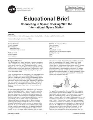
1. Educational Product
National Aeronautics and
Space Administration Educators Grades 5–12
Educational Brief
Connecting in Space: Docking With the
International Space Station
Objectives
Students will demonstrate and identify procedures, selecting the best method to complete the docking activity.
Students will identify Newton’s Laws of Motion.
Science Standards Materials (for each group of two)
Science as Inquiry String, 4.6 meters
Physical Science Pencil, sharpened
Motions and forces Tape
Position and motion of objects Space Shuttle template
Stand-off cross and docking ring template
Math Standards 2 small plastic cups
Problem Solving Straw
Communication Clay
Background Information wise axis of the vehicle. The yaw is the angular rotation movement
The International Space Station will provide a long-term orbital labo- about the heightwise axis of the vehicle. The Reaction Control
ratory in which research in biology, chemistry, physics, and other sci- Systems are located in the nose and tail sections of the Space
ences will be conducted. With an approximate mass of 456,620 Shuttle. When the systems are activated, they are fired in a direction
kilograms when it is complete, the International Space Station will be opposite to that which the Commander wishes to move. If the
the largest object humans have built in orbit. Forty-five space flights Commander wants to move to the left, he or she fires the Reaction
are required to assemble this orbiting laboratory. These flights will Control System on the right, and if the desired movement is to the
occur over a 5-year period. right, the system is fired on the left. The Space Shuttle travels toward
Mir with a force that is equal and opposite to the Reaction Control
There are three phases to the development of the International Space System firings (Newton’s Third Law).
Station. Phase One encompasses U.S. participation in the Russian
Mir space station project. Having astronauts live aboard Mir with the Yaw
Russian cosmonauts enables the United States to study the long-
term effects of space on the human body and to practice procedures – +
that will be used on the International Space Station. Phase Two of
production for the International Space Station consists of the first +
portion of assembly, while Phase Three is the second portion of
assembly.
Pitch + Roll –
–
In order for the components, crews, and supplies to be delivered to
the International Space Station, a system needs to be in place that The Space Shuttle stops within 50 meters of Mir, which is approxi-
allows the Space Shuttle to dock, or attach, to the structure. One mately one-half the length of a football field. From that position the
procedure practiced on Mir includes the docking techniques. After Space Shuttle waits for clearance from Mission Control to continue.
the Space Shuttle is launched and once inserted into an initial orbit, When the command is given to continue, the Reaction Control
the Commander uses the Orbital Maneuvering System to thrust the System is activated again and the Space Shuttle closes in on Mir at a
Space Shuttle from one orbit to another. Using the Orbital speed of about 0.05 meters per second until it reaches a distance of
Maneuvering System and Reaction Control System, the Space about 9 meters. There, the Space Shuttle stops again and waits for
Shuttle is positioned approximately 110 meters below Mir. The approximately 5 minutes. The Commander and Pilot make sure they
Reaction Control System is used to complete the approach of the can see the docking target clearly and fine-tune the alignment of the
Space Shuttle toward Mir. The Reaction Control System is used to Space Shuttle with the docking target. A large black cross called the
change speed, orbit, and attitude (pitch, roll, and yaw.) The pitch is Stand-off-Cross is mounted 30 centimeters (cm) above the back
an angular rotation about an axis parallel to the widthwise axis of a plate in the center of the target. When the Commander has the
vehicle. The roll is the angular rotation movement about the length- Stand-off Cross squarely in line with the docking target, he or she
EB-1998-07-126-HQ
EB-1998-27-126-HQ 1 Connecting in Space
2. maneuvers the Space Shuttle and makes contact with the docking nose or front of the orbiter. Have the students estimate the length of
ring. Once a series of hooks is engaged, the Space Shuttle is then string that will be needed to tie the orbiter to the string that connects
successfully docked with Mir. It takes about 2 hours for the passage the students. Allow students time to practice the docking maneuver.
between the Space Shuttle and Mir to pressurize. After the passage When the students have practiced docking, bring the class together
is pressurized, the hatch is opened and the crews exchange greet- and discuss what problems may have occurred and how those prob-
ings and supplies. lems were solved. Discuss Newton’s Laws of Motion, and have the
students give examples of those laws in their docking procedure.
These procedures, which have been learned during Phase One of
the International Space Station, have been invaluable to astronauts
and supporting ground crews. With the knowledge gained through For older students:
cooperation, these procedures will secure the future success of the Copy the docking target, and enlarge the Stand-off Cross to
International Space Station for years to come. 150 percent on heavy paper. Have the students cut out the dock-
ing target. Construct a docking apparatus by placing a piece of
Astronauts must understand the three important scientific principles clay at one end of a straw. Affix this to the bottom of a small cup.
that govern the motion of all objects whether on Earth or in space. Put a small hole through the docking target, and slide it over the
These were described by English scientist Sir Isaac Newton in 1687 straw. The straw should be tall enough to protrude 2–3 cm above
and are now called Newton’s Laws of Motion. In simple form, they the docking target (i.e., above the bottom of the cup). Identify the
are: center of the Stand-off Cross. Mount the center of the cross on
top of the straw over the center of the docking target. The cross
1. Objects at rest will stay at rest and objects in motion will stay should be 2–3 cm above the target. It needs to be below the top
in motion in a straight line unless acted upon by an unbalanced of the cup. The top of the cup simulates the actual docking ring,
force. which is the surface that is contacted by the Space Shuttle dock-
Newton’s First Law of Motion is demonstrated by the Space Shuttle ing system capture ring.
using the Reaction Control System to align itself with Mir. If the sys-
tem were not used, the Space Shuttle would continue to move in its Have the students dock the orbiter using the same techniques as
orbit instead of changing position to encounter Mir. stated for younger students. When dockings have been practiced
with two students, a third student might be added. This student
2. Force is equal to mass times acceleration. would stand directly over the docking target and Stand-off Cross
This equation is used to determine how much force is needed to and control the string with the orbiter attached. This student would
move the Space Shuttle from one position to another. communicate to the other students what they need to do in order to
line up to dock. This student would communicate to the two stu-
3. For every action there is always an opposite and dents attached to the string which way to move to line up with the
equal reaction. Stand-off Cross. The center student would use his or her hands on
A good example of this law is the use of the Reaction Control the string to control the orbiter movement in an up-and-down
System. When the Commander wants to move the Space Shuttle to motion and thus control the docking. These three students simulate
the left, he or she fires the system on the right, and if the movement the x, y, and z axes (roll, pitch, and yaw) used in docking the Space
needs to be to the right, the system fires on the left. Shuttle in orbit.
Assessment:
Each group will prepare a demonstration to show which techniques
they found to be the best procedure. In this demonstration, they
should state the reasons they chose this procedure. The students
should discuss which of Newton’s Laws of Motion pertain to the
activity.
Docking Activity Extensions:
Invite two students to demonstrate the activity for the class. 1. Restrict students’ view of the docking ring by using glasses or a
Introduce the Space Shuttle on a string apparatus. Help the students headband that has blinders affixed to the sides, such as those
tie the loose end of the string around their waists as illustrated in the used for horses. Then they should practice the activity with their
drawing. Place an empty, small plastic cup on the floor between the vision impaired.
two students. Tell the students the cup represents the docking ring
on the Mir space station. Explain that their task or mission is to get 2. Use a shorter string for the docking string.
the orbiter inside the cup without tipping the cup over. The students
may not use their hands. Allow them to demonstrate for the class. 3. Use a different size cup: taller, smaller, larger, different shape.
They will find teamwork is very important as they decide how to
maneuver. Different techniques are to move back and forth, move 4. Use two-way radio and/or video camera to simulate actual
closer together, and bend at the knees. Students should experiment communication with Mission Control.
to find the best and quickest way to dock the orbiter.
After demonstrating the activity, show the illustration and have the For more information about the International Space Station, please
students estimate how long a string they will need to tie between visit: http://station.nasa.gov
them. Make sure each team has a copy of the Shuttle template and
instruct them to tape the cut-out Space Shuttle orbiter onto a sharp-
ened pencil. The sharpened end of the pencil needs to be at the Please take a moment to evaluate this product at
http://ehb2.gsfc.nasa.gov/edcats/educational_brief
Your evaluation and suggestions are vital to continually
improving NASA educational materials. Thank you.
EB-1998-07-126-HQ 2 Connecting in Space
3. Note: Two copies of the Shuttle orbiter are provided for ease in duplication.
EB-1998-07-126-HQ 3 Connecting in Space