Download to read offline


![CONDITION ASSESSMENT OF STRUCTURES
www.superarc.net 122
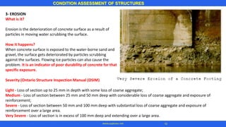
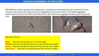
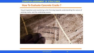
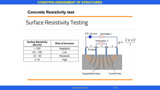
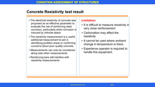
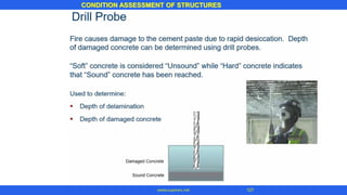
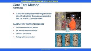
Concrete Resistivity test
The Measurement Principle
Where
a is probe spacing [cm]
V is measured potential [V]
I is the current applied [A]
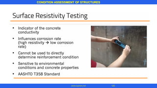
• measure the electrical resistivity of
concrete or rock in a non-destructive
test.
A current is applied to the two outer
probes, with the difference measured
by the two inner probes.
In concrete material with high electrical
resistivity the corrosion process will be
slow compared to concrete with low
resistivity in which the current can
easily pass between anode and
cathode areas
•
•](https://image.slidesharecdn.com/conditionassessmentofstructures-210927055808/85/Condition-assessment-of-structures-123-320.jpg)


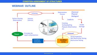
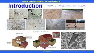
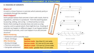
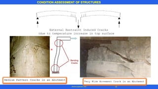
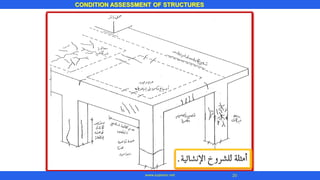
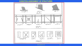
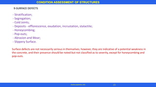
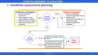
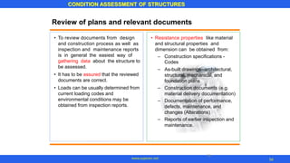
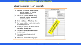
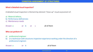
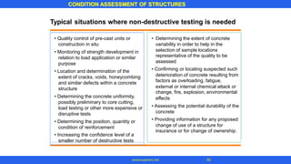
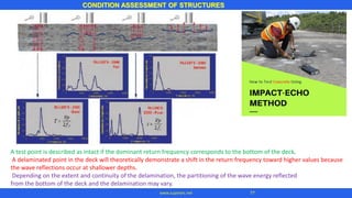
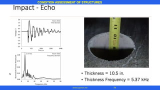
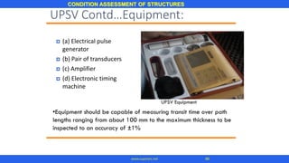
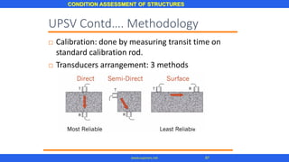
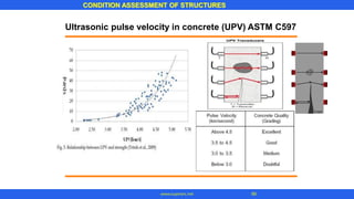
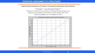
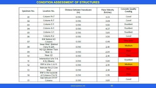
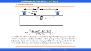
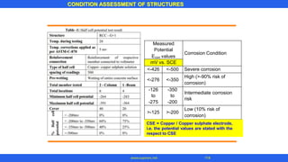
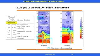
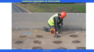
This document outlines the process for conducting a condition assessment of structures, which includes: (1) reviewing relevant documents, (2) performing a visual inspection and documenting any defects, (3) conducting field and laboratory testing, and (4) performing preliminary analysis and evaluation. The results are then used to determine if further investigation or repairs are required.


