Download as PDF, PPTX

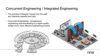
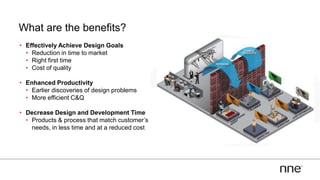

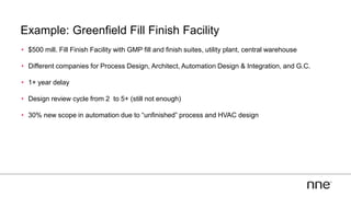
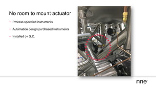
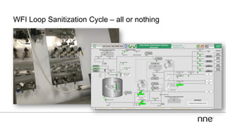
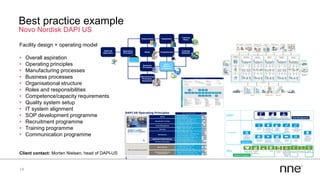
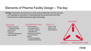
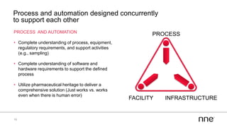
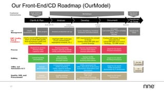
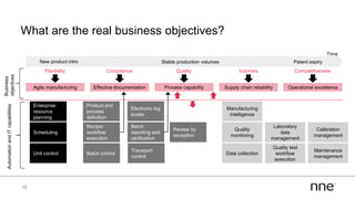


This document discusses concurrent engineering and its advantages over traditional sequential engineering approaches. Concurrent engineering involves simultaneous engineering activities that lead to higher quality designs and more efficient processes. Benefits include reduced time to market, ensuring design goals are met, and lower costs. Traditional approaches where different groups work sequentially have resulted in delays, scope changes, and integration issues. The document provides examples of pharmaceutical projects that experienced challenges due to the traditional approach and advocates for concurrent engineering best practices where process and automation are designed together. This leads to robust systems designed to meet business objectives and enables flexibility.


