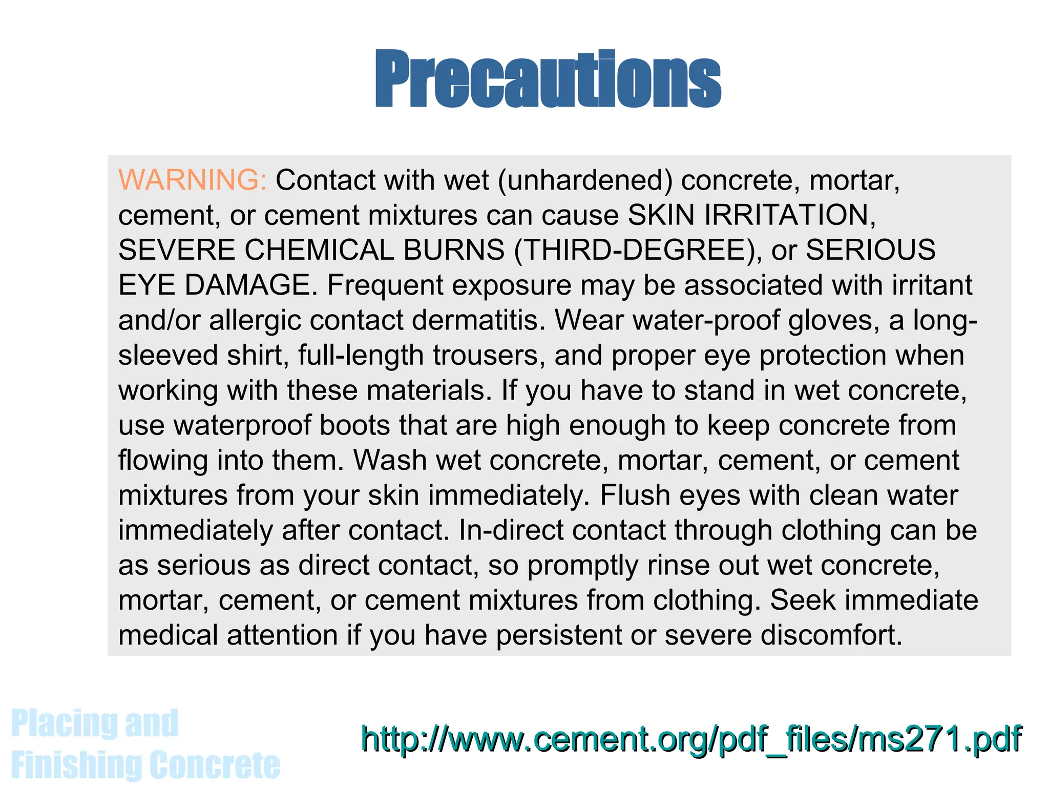
The document outlines essential guidelines and best practices for the placement and finishing of concrete, emphasizing the importance of maintaining concrete quality and proper techniques for transportation and compaction. It details preparation procedures, layering during placement, vibration techniques to eliminate air voids, and finishing methods to achieve a durable and smooth surface. It also addresses safety precautions when handling concrete materials to prevent skin irritation and chemical burns.


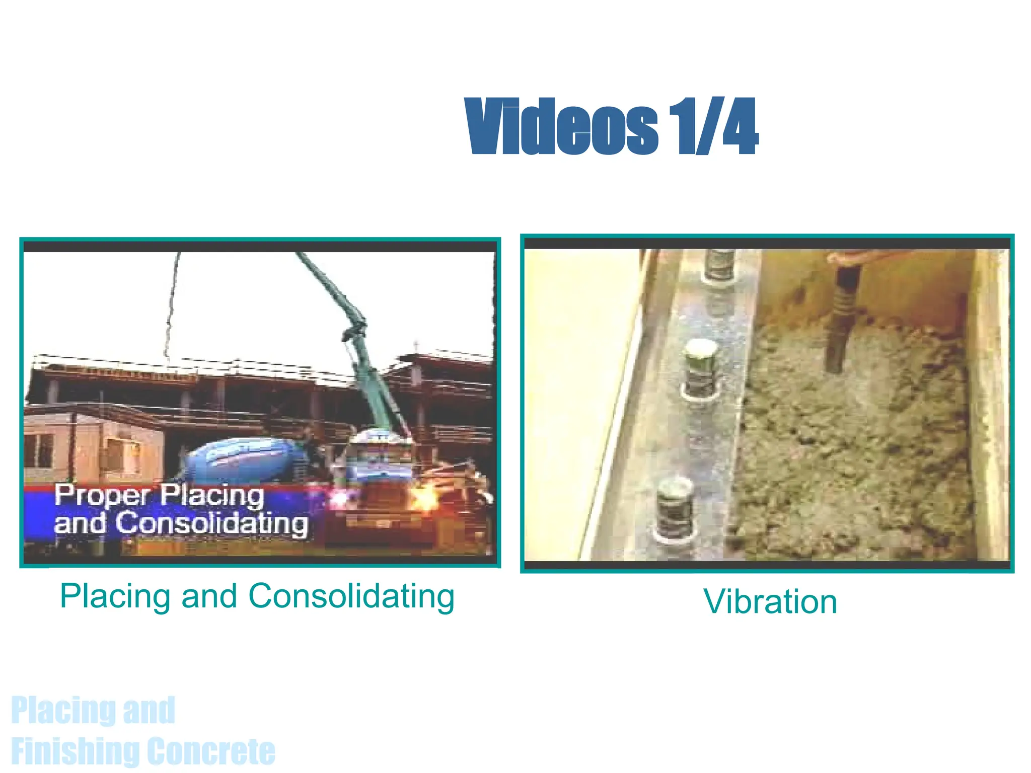
![Placing and
Finishing Concrete
Internal Vibrators
Diameter
of head,
mm (in.)
Recommended
frequency,
vibrations per
minute
Approximate
radius of
action, mm
(in.)
Rate of
placement,
m3
/h
(yd3
/h) Application
20-40
(3/4-1½)
9000-15,000
80-150
(3-6)
0.8-4
(1-5)
Plastic and flowing
concrete in thin
members. Also used
for lab test
specimens.
30-60
(1¼-2½)
8500-12,500
130-250
(5-10)
2.3-8
(3-10)
Plastic concrete in
thin walls, columns,
beams, precast piles,
thin slabs, and along
construction joints.
50-90
(2-3½)
8000-12,000
180-360
(7-14)
4.6-15
(6-20)
Stiff plastic concrete
(less than 80-mm [3-
in.] slump) in general
construction .
Adapted from ACI 309](https://image.slidesharecdn.com/concretingfinshing-240803054911-8cc21f9d/75/Concreting-finishing-in-building-construction-38-2048.jpg)


![Concrete compaction [compatibility mode]](https://cdn.slidesharecdn.com/ss_thumbnails/concretecompactionbyrj14sep13finalcompatibilitymode-140803080639-phpapp02-thumbnail.jpg?width=640&height=640&fit=bounds)


