INTRODUCTION
Verilog:
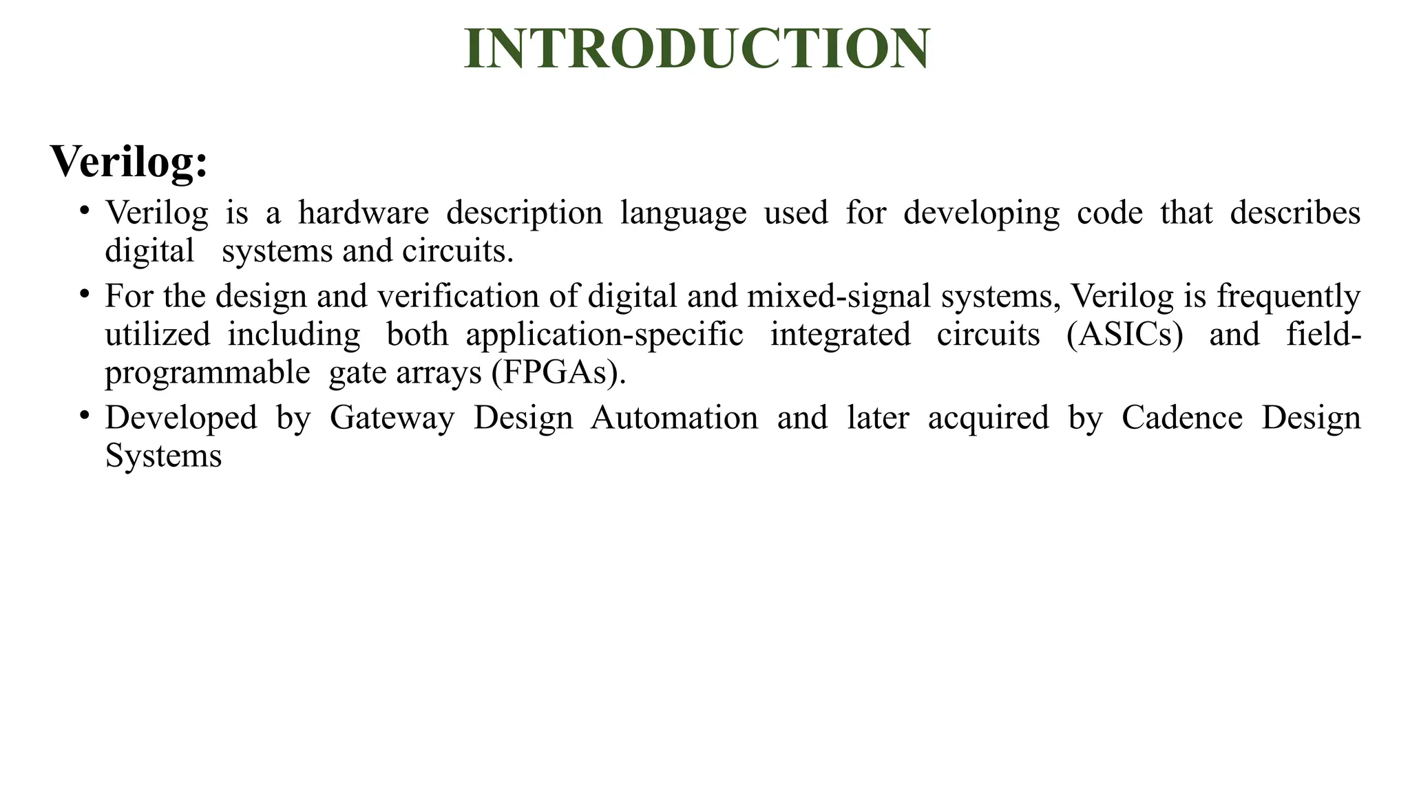
• Verilog isa hardware description language used for developing code that describes
digital systems and circuits.
• For the design and verification of digital and mixed-signal systems, Verilog is frequently
utilized including both application-specific integrated circuits (ASICs) and field-
programmable gate arrays (FPGAs).
• Developed by Gateway Design Automation and later acquired by Cadence Design
Systems
2.
Fundamentals of VLSIDesign And Verilog Basics
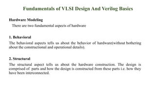
Hardware Modeling
There are two fundamental aspects of hardware
1. Behavioral
The behavioral aspects tells us about the behavior of hardware(without bothering
about the constructional and operational details).
2. Structural
The structural aspect tells us about the hardware construction. The design is
comprised of parts and how the design is constructed from these parts i.e. how they
have been interconnected.
3.
VLSI Design Methodology
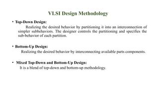
•Top-Down Design:
Realizing the desired behavior by partitioning it into an interconnection of
simpler subbehaviors. The designer controls the partitioning and specifies the
sub-behavior of each partition.
• Bottom-Up Design:
Realizing the desired behavior by interconnecting available parts components.
• Mixed Top-Down and Bottom-Up Design:
It is a blend of top-down and bottom-up methodology.
4.
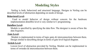
Modeling Styles
Verilog isboth, behavioral and structural language. Designs in Verilog can be
described levels of abstraction depending on needs of design.
Behavioral Level:
Used to model behavior of design without concern for the hardware
implementation detailthis level is very similar to C programming.
Dataflow Level:
Module is specified by specifying the data flow. The designer is aware of how the
data fregisters.
Gate Level:
Module is implemented in terms of logic gates & interconnections between them.
Design similar to describing design in terms of gate level logical diagram.
Switch Level:
Lowest level of abstraction provided by Verilog. Module can be implemented in
terms of swnodes & interconnection between them.
5.
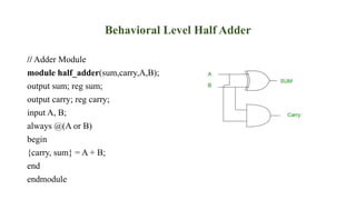
Behavioral Level HalfAdder
// Adder Module
module half_adder(sum,carry,A,B);
output sum; reg sum;
output carry; reg carry;
input A, B;
always @(A or B)
begin
{carry, sum} = A + B;
end
endmodule
6.
VLSI: Syntax, Sematics,And Core Representation
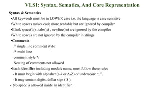
Syntax & Semantics
▪All keywords must be in LOWER case i.e. the language is case sensitive
▪White spaces makes code more readable but are ignored by compiler
▪Blank space(b) , tabs(t) , newline(n) are ignored by the compiler
▪White spaces are not ignored by the compiler in strings
▪Comments
// single line comment style
/* multi line
comment style */
Nesting of comments not allowed
▪Each identifier including module name, must follow these rules
- It must begin with alphabet (a-z or A-Z) or underscore “_”.
- It may contain digits, dollar sign ( $ ).
- No space is allowed inside an identifier.
7.
String
• A stringis a sequence of characters that are enclosed by double quotes.
• Restriction on the string is that it must be contained on a single line only.
• Strings are treated as a sequence of one – byte ASCII values.
E.g. “Hello Verilog HDL” // is a string
Identifiers
• dentifiers are names given to objects so that can be referenced in the design.
• Identifiers are made up of alphanumeric characters, the underscore( _ ) and dollar sign ( $ ).
• Identifiers start with an alphanumeric character or an underscore.
E.g. reg value // value is an identifier
Escaped Identifiers
• If a keyword or special character has to be used in an identifier, such an identifier must be
preceded by
• the backslash ( ) character and terminate with whitespace (space, tab, or newline)
E.g. reg //Keyword used
valid! //Special character used
VLSI Data Types
•Physical (NET) Data Types.
• Abstract (Register) Data Types.
• Constants.
11.
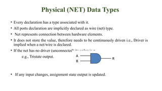
Physical (NET) DataTypes
• Every declaration has a type associated with it.
• All ports declaration are implicitly declared as wire (net) type.
• Net represents connection between hardware elements.
• It does not store the value, therefore needs to be continuously driven i.e., Driver is
implied when a net/wire is declared.
• If the net has no driver (unconnected) its value is z.
e.g., Tristate output.
• If any input changes, assignment state output is updated.
12.
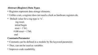
Abstract (Register) DataTypes
• Registers represent data storage elements.
• Unlike a net, a register does not need a clock as hardware registers do.
• Default value for a reg type is ‘x’.
reg reset;
initial begin
reset = 1’b1;
#100 reset = 1’b0;
end
Constants/Parameter
• Constants can be defined in a module by the keyword parameter.
• Thus, can not be used as variables.
• Improves code readability.
13.
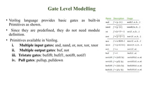
Gate Level Modelling
•Verilog language provides basic gates as built-in
Primitives as shown.
• Since they are predefined, they do not need module
definition.
• Primitives available in Verilog.
i. Multiple input gates: and, nand, or, nor, xor, xnor
ii. Multiple output gates: buf, not
iii. Tristate gates: bufif0, bufif1, notif0, notif1
iv. Pull gates: pullup, pulldown
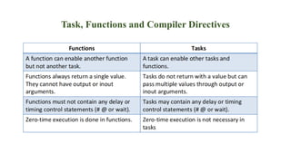
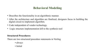
Behavioral Modeling
• Describesthe functionality in an algorithmic manner.
• After the architecture and algorithm are finalized, designers focus in building the
digital circuit to implement algorithm.
• Code independent of vendor technology.
• Logic structure implementation left to the synthesis tool
Structured Procedures:
There are two structured procedure statements in Verilog
▪ always
▪ Initial
16.
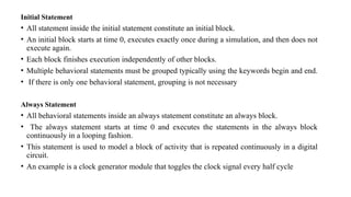
Initial Statement
• Allstatement inside the initial statement constitute an initial block.
• An initial block starts at time 0, executes exactly once during a simulation, and then does not
execute again.
• Each block finishes execution independently of other blocks.
• Multiple behavioral statements must be grouped typically using the keywords begin and end.
• If there is only one behavioral statement, grouping is not necessary
Always Statement
• All behavioral statements inside an always statement constitute an always block.
• The always statement starts at time 0 and executes the statements in the always block
continuously in a looping fashion.
• This statement is used to model a block of activity that is repeated continuously in a digital
circuit.
• An example is a clock generator module that toggles the clock signal every half cycle
17.
Procedural Assignments
• Proceduralassignments update values of reg, integer, real, or time variables.
• The value placed on a variable will remain unchanged until another procedural
assignment updates the variable with a different value.
• Syntax: ::
<assignment> :: = <!value> = <expression>
18.
• There aretwo types of procedural assignment statements: blocking and
nonblocking.
1. Blocking Assignments
2. Non-Blocking Statements
Blocking assignments:
• Blocking assignment statements are executed in the order they are specified in a
sequential block.
• A blocking assignment will not block execution of statements that follow in a
parallel block.
• The = operator is used to specify blocking assignments
reg [15:0] reg_a, reg_b; Statement reg_a[2] = 1’b1 at time = 15
Initial begin Statement reg_b[15:13] = 3’b0 at time = 25
#15 reg_a[2] = 1’b1;
#10 reg_b[15:13] = 3’b0;
19.
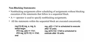
Non-Blocking Statements:
• Nonblockingassignments allow scheduling of assignments without blocking
execution of the statements that follow in a sequential block.
• A <= operator is used to specify nonblocking assignments.
• All the statements within the sequential block are executed concurrently.
20.
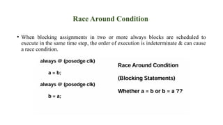
Race Around Condition
•When blocking assignments in two or more always blocks are scheduled to
execute in the same time step, the order of execution is indeterminate & can cause
a race condition.
21.
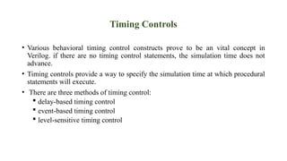
Timing Controls
• Variousbehavioral timing control constructs prove to be an vital concept in
Verilog. if there are no timing control statements, the simulation time does not
advance.
• Timing controls provide a way to specify the simulation time at which procedural
statements will execute.
• There are three methods of timing control:
delay-based timing control
event-based timing control
level-sensitive timing control


![• There are two types of procedural assignment statements: blocking and
nonblocking.
1. Blocking Assignments
2. Non-Blocking Statements
Blocking assignments:
• Blocking assignment statements are executed in the order they are specified in a
sequential block.
• A blocking assignment will not block execution of statements that follow in a
parallel block.
• The = operator is used to specify blocking assignments
reg [15:0] reg_a, reg_b; Statement reg_a[2] = 1’b1 at time = 15
Initial begin Statement reg_b[15:13] = 3’b0 at time = 25
#15 reg_a[2] = 1’b1;
#10 reg_b[15:13] = 3’b0;](https://image.slidesharecdn.com/systemverilog-250320152534-4255156a/85/systemverilog-and-veriog-presentation-18-320.jpg)