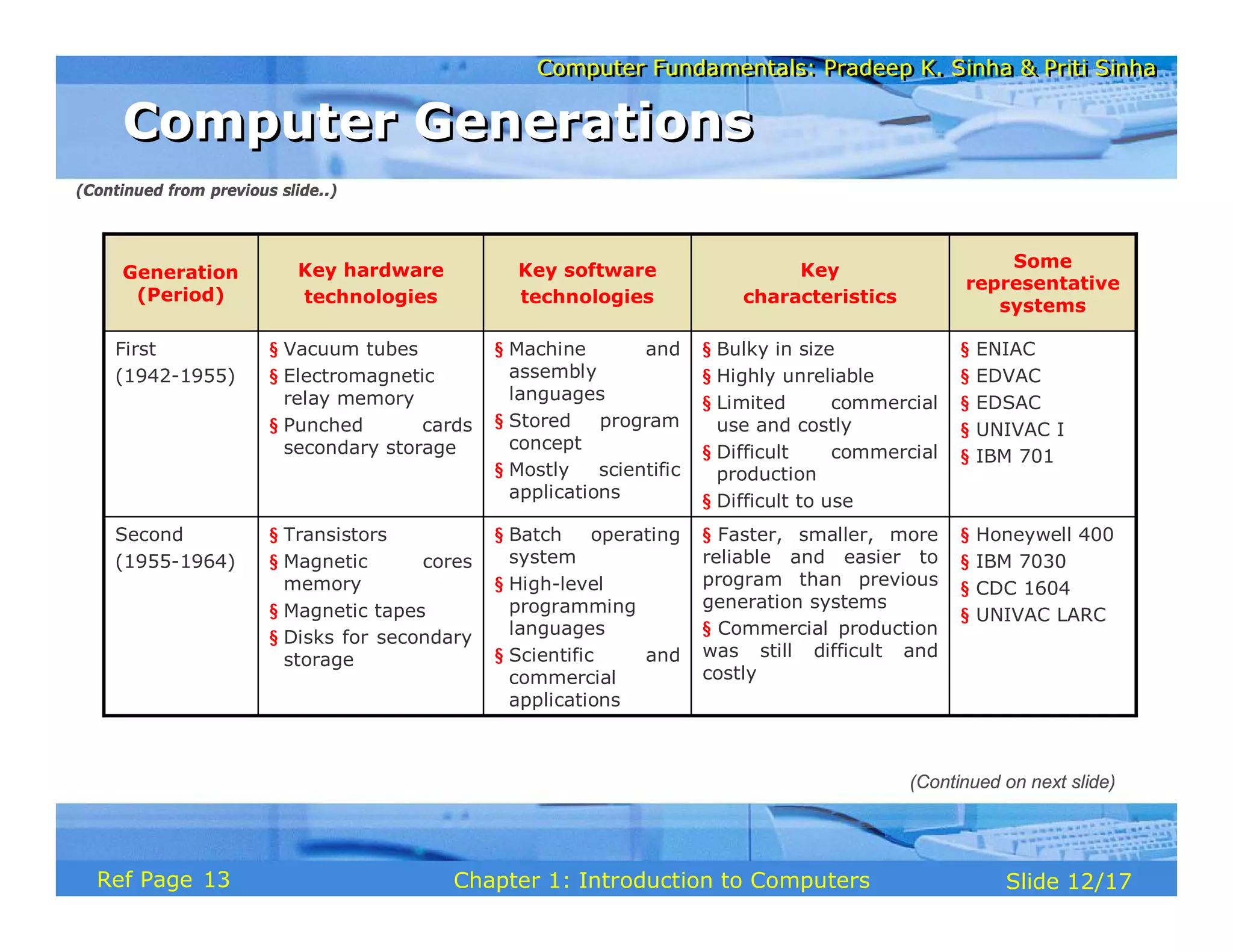
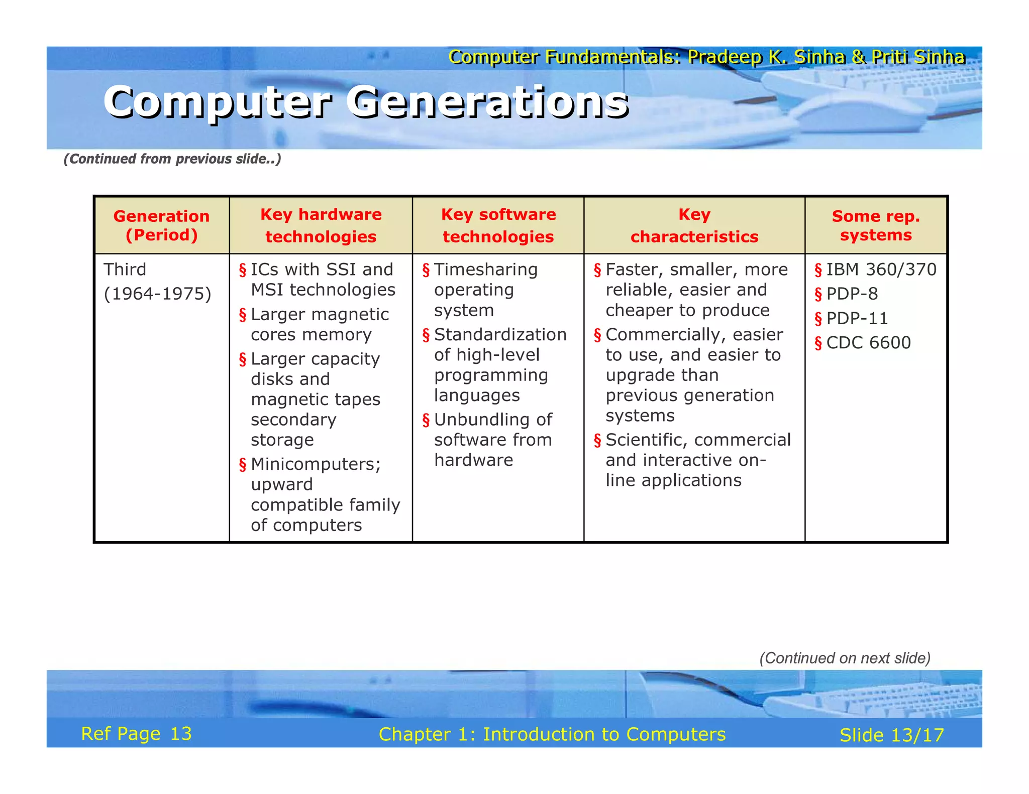
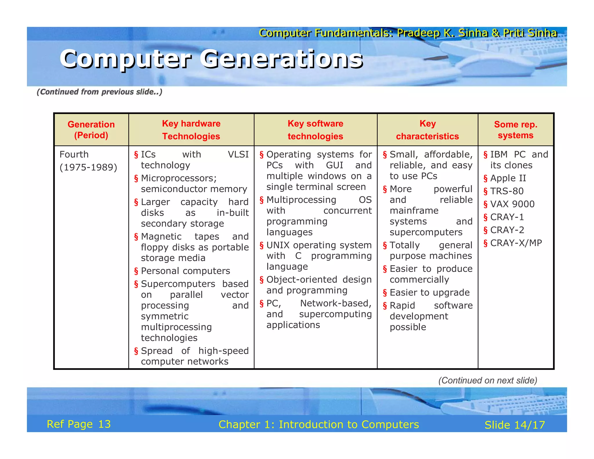
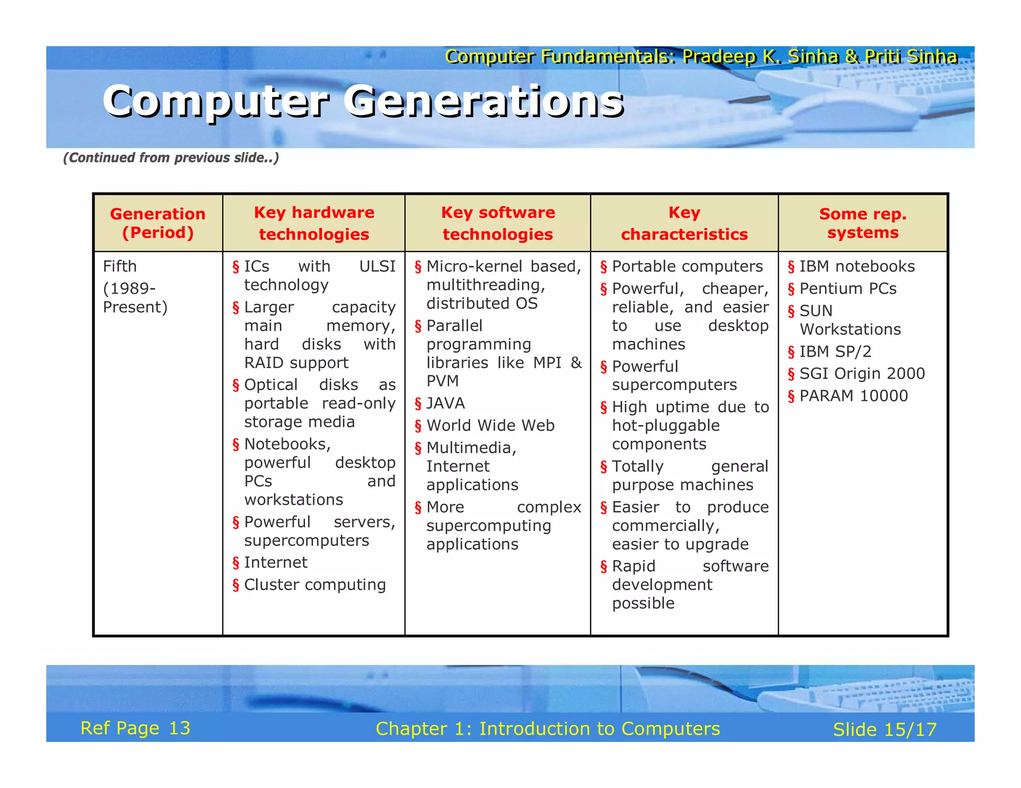
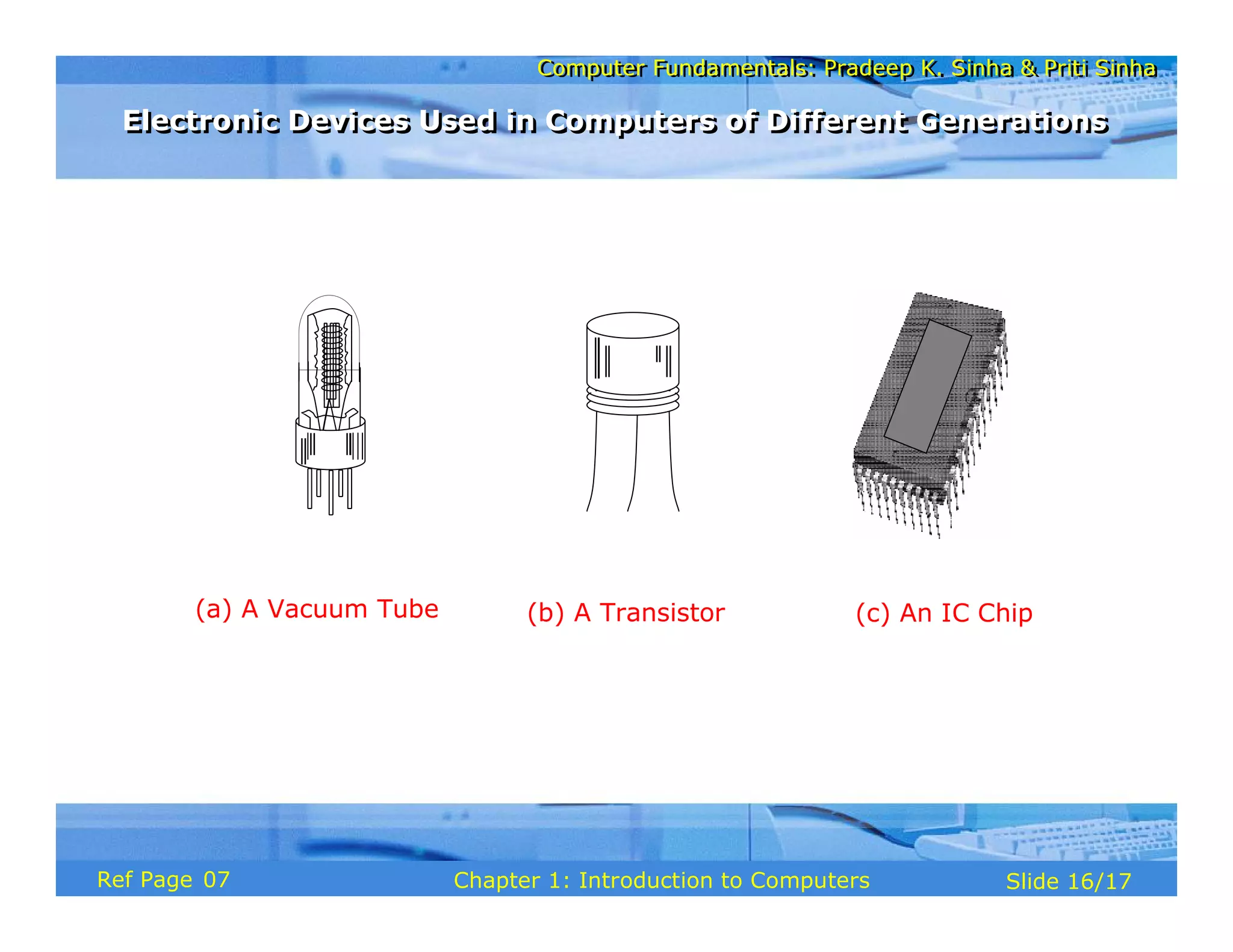
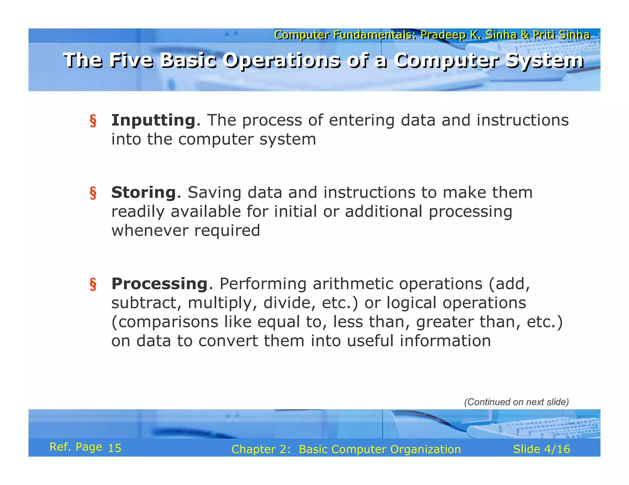
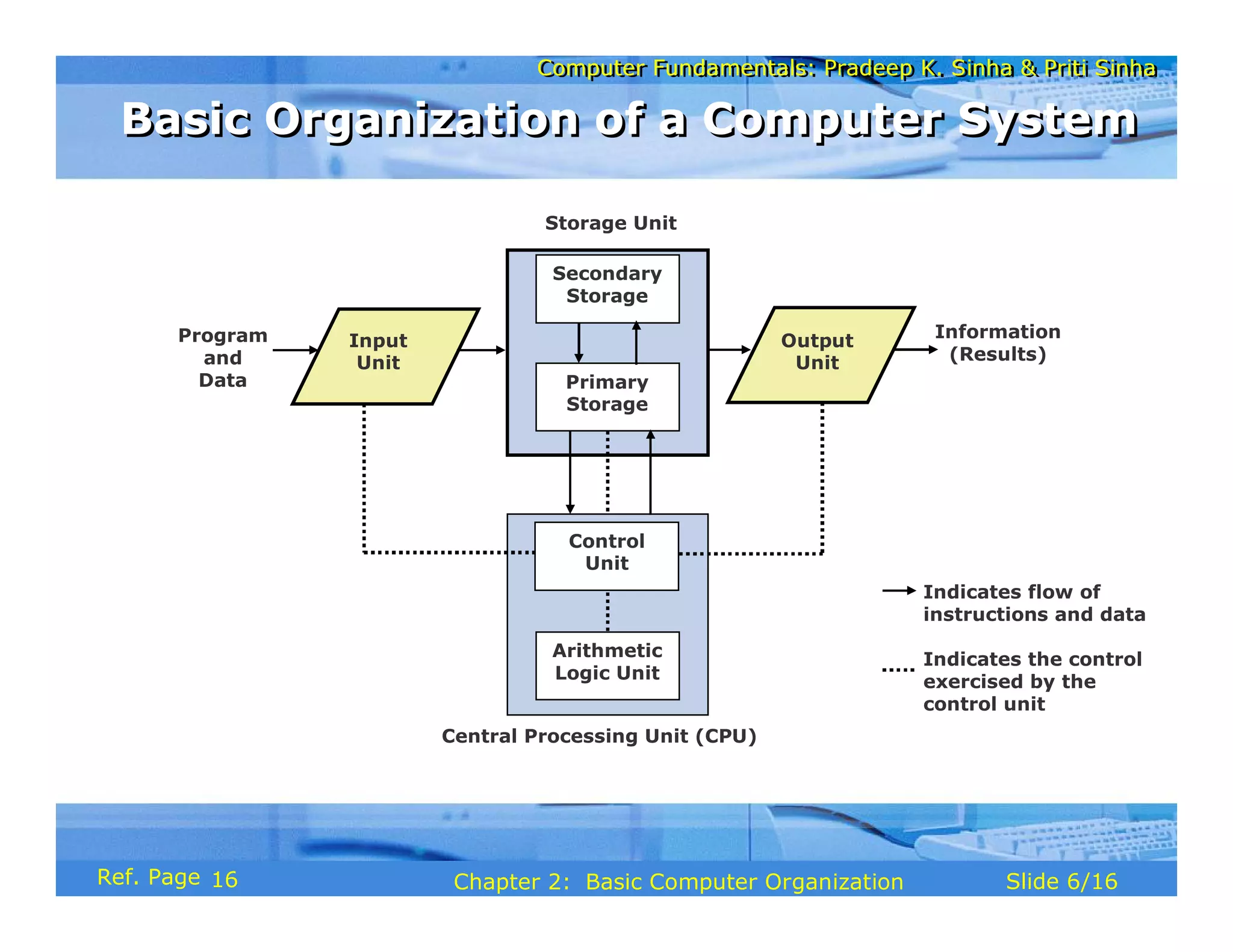
Computer Fundamentals: Pradeep K. Sinha & Priti Sinha
Slide 1/17
Chapter 1: Introduction to Computers
Ref Page
Computer Fundamentals: Pradeep K. Sinha & Priti Sinha
Slide 2/17
Chapter 1: Introduction to Computers
Ref Page
Learning Objectives
Learning Objectives
In this chapter you will learn about:
§ Computer
§ Data processing
§ Characteristic features of computers
§ Computers’ evolution to their present form
§ Computer generations
§ Characteristic features of each computer generation
01
Computer Fundamentals: Pradeep K. Sinha & Priti Sinha
Slide 3/17
Chapter 1: Introduction to Computers
Ref Page
§ The word computer comes from the word “compute”,
which means, “to calculate”
§ Thereby, a computer is an electronic device that can
perform arithmetic operations at high speed
§ A computer is also called a data processor because it can
store, process, and retrieve data whenever desired
Computer
Computer
01
Computer Fundamentals: Pradeep K. Sinha & Priti Sinha
Slide 4/17
Chapter 1: Introduction to Computers
Ref Page
Data Processing
Data Processing
The activity of processing data using a computer is called
data processing
Data
Capture Data
Manipulate Data
Output Results
Information
Data is raw material used as input and information is
processed data obtained as output of data processing
01
Computer Fundamentals: Pradeep K. Sinha & Priti Sinha
Slide 5/17
Chapter 1: Introduction to Computers
Ref Page
1) Automatic: Given a job, computer can work on it
automatically without human interventions
2) Speed: Computer can perform data processing jobs
very fast, usually measured in microseconds (10-6),
nanoseconds (10-9), and picoseconds (10-12)
3) Accuracy: Accuracy of a computer is consistently high
and the degree of its accuracy depends upon its design.
Computer errors caused due to incorrect input data or
unreliable programs are often referred to as Garbage-
In-Garbage-Out (GIGO)
(Continued on next slide)
Characteristics of Computers
02
Computer Fundamentals: Pradeep K. Sinha & Priti Sinha
Slide 6/17
Chapter 1: Introduction to Computers
Ref Page
4) Diligence: Computer is free from monotony, tiredness,
and lack of concentration. It can continuously work for
hours without creating any error and without grumbling
5) Versatility: Computer is capable of performing almost
any task, if the task can be reduced to a finite series of
logical steps
6) Power of Remembering: Computer can store and
recall any amount of information because of its
secondary storage capability. It forgets or looses certain
information only when it is asked to do so
(Continued from previous slide..)
Characteristics of Computers
(Continued on next slide)
02
Computer Fundamentals: Pradeep K. Sinha & Priti Sinha
Slide 7/17
Chapter 1: Introduction to Computers
Ref Page
7) No I.Q.: A computer does only what it is programmed
to do. It cannot take its own decision in this regard
8) No Feelings: Computers are devoid of emotions. Their
judgement is based on the instructions given to them in
the form of programs that are written by us (human
beings)
(Continued from previous slide..)
(Continued on next slide)
Characteristics of Computers
03
Computer Fundamentals: Pradeep K. Sinha & Priti Sinha
Slide 8/17
Chapter 1: Introduction to Computers
Ref Page
Evolution of Computers
§ Blaise Pascal invented the first mechanical adding
machine in 1642
§ Baron Gottfried Wilhelm von Leibniz invented the first
calculator for multiplication in 1671
§ Keyboard machines originated in the United States
around 1880
§ Around 1880, Herman Hollerith came up with the concept
of punched cards that were extensively used as input
media until late 1970s
03
Computer Fundamentals: Pradeep K. Sinha & Priti Sinha
Slide 9/17
Chapter 1: Introduction to Computers
Ref Page
§ Charles Babbage is considered to be the father of
modern digital computers
§ He designed “Difference Engine” in 1822
§ He designed a fully automatic analytical engine in
1842 for performing basic arithmetic functions
§ His efforts established a number of principles that
are fundamental to the design of any digital
computer
(Continued from previous slide..)
(Continued on next slide)
Evolution of Computers
03
Computer Fundamentals: Pradeep K. Sinha & Priti Sinha
Slide 10/17
Chapter 1: Introduction to Computers
Ref Page
Some Well Known Early Computers
§ The Mark I Computer (1937-44)
§ The Atanasoff-Berry Computer (1939-42)
§ The ENIAC (1943-46)
§ The EDVAC (1946-52)
§ The EDSAC (1947-49)
§ Manchester Mark I (1948)
§ The UNIVAC I (1951)
03
Computer Fundamentals: Pradeep K. Sinha & Priti Sinha
Slide 11/17
Chapter 1: Introduction to Computers
Ref Page
§ “Generation” in computer talk is a step in technology. It
provides a framework for the growth of computer industry
§ Originally it was used to distinguish between various
hardware technologies, but now it has been extended to
include both hardware and software
§ Till today, there are five computer generations
Computer Generations
(Continued on next slide)
05
Computer Fundamentals: Pradeep K. Sinha & Priti Sinha
Slide 12/17
Chapter 1: Introduction to Computers
Ref Page
§ Honeywell 400
§ IBM 7030
§ CDC 1604
§ UNIVAC LARC
§ Faster, smaller, more
reliable and easier to
program than previous
generation systems
§ Commercial production
was still difficult and
costly
§ Batch operating
system
§ High-level
programming
languages
§ Scientific and
commercial
applications
§ Transistors
§ Magnetic cores
memory
§ Magnetic tapes
§ Disks for secondary
storage
Second
(1955-1964)
§ ENIAC
§ EDVAC
§ EDSAC
§ UNIVAC I
§ IBM 701
§ Bulky in size
§ Highly unreliable
§ Limited commercial
use and costly
§ Difficult commercial
production
§ Difficult to use
§ Machine and
assembly
languages
§ Stored program
concept
§ Mostly scientific
applications
§ Vacuum tubes
§ Electromagnetic
relay memory
§ Punched cards
secondary storage
First
(1942-1955)
Some
representative
systems
Key
characteristics
Key software
technologies
Key hardware
technologies
Generation
(Period)
(Continued from previous slide..)
(Continued on next slide)
Computer Generations
13
Computer Fundamentals: Pradeep K. Sinha & Priti Sinha
Slide 13/17
Chapter 1: Introduction to Computers
Ref Page
§ IBM 360/370
§ PDP-8
§ PDP-11
§ CDC 6600
§ Faster, smaller, more
reliable, easier and
cheaper to produce
§ Commercially, easier
to use, and easier to
upgrade than
previous generation
systems
§ Scientific, commercial
and interactive on-
line applications
§ Timesharing
operating
system
§ Standardization
of high-level
programming
languages
§ Unbundling of
software from
hardware
§ ICs with SSI and
MSI technologies
§ Larger magnetic
cores memory
§ Larger capacity
disks and
magnetic tapes
secondary
storage
§ Minicomputers;
upward
compatible family
of computers
Third
(1964-1975)
Some rep.
systems
Key
characteristics
Key software
technologies
Key hardware
technologies
Generation
(Period)
(Continued from previous slide..)
(Continued on next slide)
Computer Generations
13
Computer Fundamentals: Pradeep K. Sinha & Priti Sinha
Slide 14/17
Chapter 1: Introduction to Computers
Ref Page
§ IBM PC and
its clones
§ Apple II
§ TRS-80
§ VAX 9000
§ CRAY-1
§ CRAY-2
§ CRAY-X/MP
§ Small, affordable,
reliable, and easy
to use PCs
§ More powerful
and reliable
mainframe
systems and
supercomputers
§ Totally general
purpose machines
§ Easier to produce
commercially
§ Easier to upgrade
§ Rapid software
development
possible
§ Operating systems for
PCs with GUI and
multiple windows on a
single terminal screen
§ Multiprocessing OS
with concurrent
programming
languages
§ UNIX operating system
with C programming
language
§ Object-oriented design
and programming
§ PC, Network-based,
and supercomputing
applications
§ ICs with VLSI
technology
§ Microprocessors;
semiconductor memory
§ Larger capacity hard
disks as in-built
secondary storage
§ Magnetic tapes and
floppy disks as portable
storage media
§ Personal computers
§ Supercomputers based
on parallel vector
processing and
symmetric
multiprocessing
technologies
§ Spread of high-speed
computer networks
Fourth
(1975-1989)
Some rep.
systems
Key
characteristics
Key software
technologies
Key hardware
Technologies
Generation
(Period)
(Continued from previous slide..)
(Continued on next slide)
Computer Generations
13
Computer Fundamentals: Pradeep K. Sinha & Priti Sinha
Slide 15/17
Chapter 1: Introduction to Computers
Ref Page
§ IBM notebooks
§ Pentium PCs
§ SUN
Workstations
§ IBM SP/2
§ SGI Origin 2000
§ PARAM 10000
§ Portable computers
§ Powerful, cheaper,
reliable, and easier
to use desktop
machines
§ Powerful
supercomputers
§ High uptime due to
hot-pluggable
components
§ Totally general
purpose machines
§ Easier to produce
commercially,
easier to upgrade
§ Rapid software
development
possible
§ Micro-kernel based,
multithreading,
distributed OS
§ Parallel
programming
libraries like MPI &
PVM
§ JAVA
§ World Wide Web
§ Multimedia,
Internet
applications
§ More complex
supercomputing
applications
§ ICs with ULSI
technology
§ Larger capacity
main memory,
hard disks with
RAID support
§ Optical disks as
portable read-only
storage media
§ Notebooks,
powerful desktop
PCs and
workstations
§ Powerful servers,
supercomputers
§ Internet
§ Cluster computing
Fifth
(1989-
Present)
Some rep.
systems
Key
characteristics
Key software
technologies
Key hardware
technologies
Generation
(Period)
(Continued from previous slide..)
Computer Generations
13
Computer Fundamentals: Pradeep K. Sinha & Priti Sinha
Slide 16/17
Chapter 1: Introduction to Computers
Ref Page
(c) An IC Chip
(b) A Transistor
(a) A Vacuum Tube
Electronic Devices Used in Computers of Different Generations
07
Computer Fundamentals: Pradeep K. Sinha & Priti Sinha
Slide 17/17
Chapter 1: Introduction to Computers
Ref Page
Key Words/Phrases
Key Words/Phrases
§ Computer
§ Computer generations
§ Computer Supported Cooperative
Working (CSCW)
§ Data
§ Data processing
§ Data processor
§ First-generation computers
§ Fourth-generation computers
§ Garbage-in-garbage-out (GIGO)
§ Graphical User Interface (GUI)
§ Groupware
§ Information
§ Integrated Circuit (IC)
§ Large Scale Integration (VLSI)
§ Medium Scale Integration (MSI)
§ Microprocessor
§ Personal Computer (PC)
§ Second-generation computers
§ Small Scale Integration (SSI)
§ Stored program concept
§ Third-generation computers
§ Transistor
§ Ultra Large Scale Integration
(ULSI)
§ Vacuum tubes
12
Computer Fundamentals: Pradeep K. Sinha & Priti Sinha
Slide 1/16
Chapter 2: Basic Computer Organization
Ref. Page
Computer Fundamentals: Pradeep K. Sinha & Priti Sinha
Slide 2/16
Chapter 2: Basic Computer Organization
Ref. Page
In this chapter you will learn about:
§ Basic operations performed by all types of computer
systems
§ Basic organization of a computer system
§ Input unit and its functions
§ Output unit and its functions
§ Storage unit and its functions
§ Types of storage used in a computer system
Learning Objectives
Learning Objectives
(Continued on next slide)
15
Computer Fundamentals: Pradeep K. Sinha & Priti Sinha
Slide 3/16
Chapter 2: Basic Computer Organization
Ref. Page
§ Arithmetic Logic Unit (ALU)
§ Control Unit (CU)
§ Central Processing Unit (CPU)
§ Computer as a system
Learning Objectives
Learning Objectives
(Continued from previous slide..)
15
Computer Fundamentals: Pradeep K. Sinha & Priti Sinha
Slide 4/16
Chapter 2: Basic Computer Organization
Ref. Page
§ Inputting. The process of entering data and instructions
into the computer system
§ Storing. Saving data and instructions to make them
readily available for initial or additional processing
whenever required
§ Processing. Performing arithmetic operations (add,
subtract, multiply, divide, etc.) or logical operations
(comparisons like equal to, less than, greater than, etc.)
on data to convert them into useful information
The Five Basic Operations of a Computer System
(Continued on next slide)
15
Computer Fundamentals: Pradeep K. Sinha & Priti Sinha
Slide 5/16
Chapter 2: Basic Computer Organization
Ref. Page
§ Outputting. The process of producing useful information
or results for the user such as a printed report or visual
display
§ Controlling. Directing the manner and sequence in which
all of the above operations are performed
The Five Basic Operations of a Computer System
15
Computer Fundamentals: Pradeep K. Sinha & Priti Sinha
Slide 6/16
Chapter 2: Basic Computer Organization
Ref. Page
Central Processing Unit (CPU)
Storage Unit
Secondary
Storage
Primary
Storage
Control
Unit
Arithmetic
Logic Unit
Input
Unit
Output
Unit
Program
and
Data
Information
(Results)
Indicates flow of
instructions and data
Indicates the control
exercised by the
control unit
Basic Organization of a Computer System
16
Computer Fundamentals: Pradeep K. Sinha & Priti Sinha
Slide 7/16
Chapter 2: Basic Computer Organization
Ref. Page
An input unit of a computer system performs the
following functions:
1. It accepts (or reads) instructions and data from outside
world
2. It converts these instructions and data in computer
acceptable form
3. It supplies the converted instructions and data to the
computer system for further processing
Input Unit
Input Unit
16
Computer Fundamentals: Pradeep K. Sinha & Priti Sinha
Slide 8/16
Chapter 2: Basic Computer Organization
Ref. Page
An output unit of a computer system performs the
following functions:
1. It accepts the results produced by the computer, which
are in coded form and hence, cannot be easily
understood by us
2. It converts these coded results to human acceptable
(readable) form
3. It supplies the converted results to outside world
Output Unit
Output Unit
16
Computer Fundamentals: Pradeep K. Sinha & Priti Sinha
Slide 9/16
Chapter 2: Basic Computer Organization
Ref. Page
The storage unit of a computer system holds (or stores)
the following :
1. Data and instructions required for processing (received
from input devices)
2. Intermediate results of processing
3. Final results of processing, before they are released to
an output device
Storage Unit
Storage Unit
17
Computer Fundamentals: Pradeep K. Sinha & Priti Sinha
Slide 10/16
Chapter 2: Basic Computer Organization
Ref. Page
§ Primary storage
§ Used to hold running program instructions
§ Used to hold data, intermediate results, and
results of ongoing processing of job(s)
§ Fast in operation
§ Small Capacity
§ Expensive
§ Volatile (looses data on power dissipation)
Two Types of Storage
(Continued on next slide)
17
Computer Fundamentals: Pradeep K. Sinha & Priti Sinha
Slide 11/16
Chapter 2: Basic Computer Organization
Ref. Page
§ Secondary storage
§ Used to hold stored program instructions
§ Used to hold data and information of stored jobs
§ Slower than primary storage
§ Large Capacity
§ Lot cheaper that primary storage
§ Retains data even without power
Two Types of Storage
(Continued from previous slide..)
17
Computer Fundamentals: Pradeep K. Sinha & Priti Sinha
Slide 12/16
Chapter 2: Basic Computer Organization
Ref. Page
Arithmetic Logic Unit of a computer system is the place
where the actual executions of instructions takes place during
processing operation
Arithmetic Logic Unit (ALU)
18
Computer Fundamentals: Pradeep K. Sinha & Priti Sinha
Slide 13/16
Chapter 2: Basic Computer Organization
Ref. Page
Control Unit of a computer system manages and coordinates
the operations of all other components of the computer
system
Control Unit (CU)
Control Unit (CU)
18
Computer Fundamentals: Pradeep K. Sinha & Priti Sinha
Slide 14/16
Chapter 2: Basic Computer Organization
Ref. Page
Arithmetic
Logic Unit
(ALU)
Control Unit
(CU)
=
Central
Processing
Unit (CPU)
§ It is the brain of a computer system
§ It is responsible for controlling the operations of
all other units of a computer system
+
Central Processing Unit (CPU)
18
Computer Fundamentals: Pradeep K. Sinha & Priti Sinha
Slide 15/16
Chapter 2: Basic Computer Organization
Ref. Page
A system has following three characteristics:
1. A system has more than one element
2. All elements of a system are logically related
3. All elements of a system are controlled in a manner to
achieve the system goal
A computer is a system as it comprises of integrated
components (input unit, output unit, storage unit, and CPU)
that work together to perform the steps called for in the
executing program
The System Concept
The System Concept
18
Computer Fundamentals: Pradeep K. Sinha & Priti Sinha
Slide 16/16
Chapter 2: Basic Computer Organization
Ref. Page
§ Arithmetic Logic Unit (ALU)
§ Auxiliary storage
§ Central Processing Unit (CPU)
§ Computer system
§ Control Unit (CU)
§ Controlling
§ Input interface
§ Input unit
§ Inputting
§ Main memory
§ Output interface
§ Output unit
§ Outputting
§ Primate storage
§ Processing
§ Secondary storage
§ Storage unit
§ Storing
§ System
Key Words/Phrases
Key Words/Phrases
19
Computer Fundamentals: Pradeep K. Sinha & Priti Sinha
Slide 1/40
Chapter 3: Number Systems
Ref Page
Computer Fundamentals: Pradeep K. Sinha & Priti Sinha
Slide 2/40
Chapter 3: Number Systems
Ref Page
In this chapter you will learn about:
§ Non-positional number system
§ Positional number system
§ Decimal number system
§ Binary number system
§ Octal number system
§ Hexadecimal number system
Learning Objectives
Learning Objectives
(Continued on next slide)
20
Computer Fundamentals: Pradeep K. Sinha & Priti Sinha
Slide 3/40
Chapter 3: Number Systems
Ref Page
§ Convert a number’s base
§ Another base to decimal base
§ Decimal base to another base
§ Some base to another base
§ Shortcut methods for converting
§ Binary to octal number
§ Octal to binary number
§ Binary to hexadecimal number
§ Hexadecimal to binary number
§ Fractional numbers in binary number system
Learning Objectives
Learning Objectives
(Continued from previous slide..)
20
Computer Fundamentals: Pradeep K. Sinha & Priti Sinha
Slide 4/40
Chapter 3: Number Systems
Ref Page
Two types of number systems are:
§ Non-positional number systems
§ Positional number systems
Number Systems
Number Systems
20
Computer Fundamentals: Pradeep K. Sinha & Priti Sinha
Slide 5/40
Chapter 3: Number Systems
Ref Page
§ Characteristics
§ Use symbols such as I for 1, II for 2, III for 3, IIII
for 4, IIIII for 5, etc
§ Each symbol represents the same value regardless
of its position in the number
§ The symbols are simply added to find out the value
of a particular number
§ Difficulty
§ It is difficult to perform arithmetic with such a
number system
Non-positional Number Systems
20
Computer Fundamentals: Pradeep K. Sinha & Priti Sinha
Slide 6/40
Chapter 3: Number Systems
Ref Page
§ Characteristics
§ Use only a few symbols called digits
§ These symbols represent different values depending
on the position they occupy in the number
Positional Number Systems
(Continued on next slide)
20
Computer Fundamentals: Pradeep K. Sinha & Priti Sinha
Slide 7/40
Chapter 3: Number Systems
Ref Page
§ The value of each digit is determined by:
1. The digit itself
2. The position of the digit in the number
3. The base of the number system
(base = total number of digits in the number
system)
§ The maximum value of a single digit is
always equal to one less than the value of
the base
Positional Number Systems
(Continued from previous slide..)
21
Computer Fundamentals: Pradeep K. Sinha & Priti Sinha
Slide 8/40
Chapter 3: Number Systems
Ref Page
Characteristics
§ A positional number system
§ Has 10 symbols or digits (0, 1, 2, 3, 4, 5, 6, 7,
8, 9). Hence, its base = 10
§ The maximum value of a single digit is 9 (one
less than the value of the base)
§ Each position of a digit represents a specific
power of the base (10)
§ We use this number system in our day-to-day
life
Decimal Number System
(Continued on next slide)
21
Computer Fundamentals: Pradeep K. Sinha & Priti Sinha
Slide 9/40
Chapter 3: Number Systems
Ref Page
Example
258610 = (2 x 10³) + (5 x 10²) + (8 x 101) + (6 x 100)
= 2000 + 500 + 80 + 6
Decimal Number System
(Continued from previous slide..)
21
Computer Fundamentals: Pradeep K. Sinha & Priti Sinha
Slide 10/40
Chapter 3: Number Systems
Ref Page
Characteristics
§ A positional number system
§ Has only 2 symbols or digits (0 and 1). Hence its
base = 2
§ The maximum value of a single digit is 1 (one less
than the value of the base)
§ Each position of a digit represents a specific power
of the base (2)
§ This number system is used in computers
Binary Number System
(Continued on next slide)
21
Computer Fundamentals: Pradeep K. Sinha & Priti Sinha
Slide 11/40
Chapter 3: Number Systems
Ref Page
Example
101012 = (1 x 24) + (0 x 23) + (1 x 22) + (0 x 21) x (1 x 20)
= 16 + 0 + 4 + 0 + 1
= 2110
Binary Number System
(Continued from previous slide..)
21
Computer Fundamentals: Pradeep K. Sinha & Priti Sinha
Slide 12/40
Chapter 3: Number Systems
Ref Page
In order to be specific about which number system we
are referring to, it is a common practice to indicate the
base as a subscript. Thus, we write:
101012 = 2110
Representing Numbers in Different Number
Systems
Representing Numbers in Different Number
Systems
21
Computer Fundamentals: Pradeep K. Sinha & Priti Sinha
Slide 13/40
Chapter 3: Number Systems
Ref Page
§ Bit stands for binary digit
§ A bit in computer terminology means either a 0 or a 1
§ A binary number consisting of n bits is called an n-bit
number
Bit
Bit
22
Computer Fundamentals: Pradeep K. Sinha & Priti Sinha
Slide 14/40
Chapter 3: Number Systems
Ref Page
Characteristics
§ A positional number system
§ Has total 8 symbols or digits (0, 1, 2, 3, 4, 5, 6, 7).
Hence, its base = 8
§ The maximum value of a single digit is 7 (one less
than the value of the base
§ Each position of a digit represents a specific power of
the base (8)
Octal Number System
Octal Number System
(Continued on next slide)
22
Computer Fundamentals: Pradeep K. Sinha & Priti Sinha
Slide 15/40
Chapter 3: Number Systems
Ref Page
§ Since there are only 8 digits, 3 bits (23 = 8) are
sufficient to represent any octal number in binary
Example
20578 = (2 x 83) + (0 x 82) + (5 x 81) + (7 x 80)
= 1024 + 0 + 40 + 7
= 107110
Octal Number System
Octal Number System
(Continued from previous slide..)
22
Computer Fundamentals: Pradeep K. Sinha & Priti Sinha
Slide 16/40
Chapter 3: Number Systems
Ref Page
Characteristics
§ A positional number system
§ Has total 16 symbols or digits (0, 1, 2, 3, 4, 5, 6, 7,
8, 9, A, B, C, D, E, F). Hence its base = 16
§ The symbols A, B, C, D, E and F represent the
decimal values 10, 11, 12, 13, 14 and 15
respectively
§ The maximum value of a single digit is 15 (one less
than the value of the base)
Hexadecimal Number System
(Continued on next slide)
22
Computer Fundamentals: Pradeep K. Sinha & Priti Sinha
Slide 17/40
Chapter 3: Number Systems
Ref Page
§ Each position of a digit represents a specific power
of the base (16)
§ Since there are only 16 digits, 4 bits (24 = 16) are
sufficient to represent any hexadecimal number in
binary
Example
1AF16 = (1 x 162) + (A x 161) + (F x 160)
= 1 x 256 + 10 x 16 + 15 x 1
= 256 + 160 + 15
= 43110
Hexadecimal Number System
(Continued from previous slide..)
22
Computer Fundamentals: Pradeep K. Sinha & Priti Sinha
Slide 18/40
Chapter 3: Number Systems
Ref Page
Method
Step 1: Determine the column (positional) value of
each digit
Step 2: Multiply the obtained column values by the
digits in the corresponding columns
Step 3: Calculate the sum of these products
Converting a Number of Another Base to a
Decimal Number
Converting a Number of Another Base to a
Decimal Number
(Continued on next slide)
23
Computer Fundamentals: Pradeep K. Sinha & Priti Sinha
Slide 19/40
Chapter 3: Number Systems
Ref Page
Example
47068 = ?10
47068 = 4 x 83 + 7 x 82 + 0 x 81 + 6 x 80
= 4 x 512 + 7 x 64 + 0 + 6 x 1
= 2048 + 448 + 0 + 6
= 250210
Common
values
multiplied
by the
corresponding
digits
Sum of these
products
(Continued from previous slide..)
Converting a Number of Another Base to a
Decimal Number
Converting a Number of Another Base to a
Decimal Number
23
Computer Fundamentals: Pradeep K. Sinha & Priti Sinha
Slide 20/40
Chapter 3: Number Systems
Ref Page
Division-Remainder Method
Step 1: Divide the decimal number to be converted by
the value of the new base
Step 2: Record the remainder from Step 1 as the
rightmost digit (least significant digit) of the
new base number
Step 3: Divide the quotient of the previous divide by the
new base
Converting a Decimal Number to a Number of
Another Base
Converting a Decimal Number to a Number of
Another Base
(Continued on next slide)
25
Computer Fundamentals: Pradeep K. Sinha & Priti Sinha
Slide 21/40
Chapter 3: Number Systems
Ref Page
Step 4: Record the remainder from Step 3 as the next
digit (to the left) of the new base number
Repeat Steps 3 and 4, recording remainders from right to
left, until the quotient becomes zero in Step 3
Note that the last remainder thus obtained will be the most
significant digit (MSD) of the new base number
Converting a Decimal Number to a Number of
Another Base
Converting a Decimal Number to a Number of
Another Base
(Continued from previous slide..)
(Continued on next slide)
25
Computer Fundamentals: Pradeep K. Sinha & Priti Sinha
Slide 22/40
Chapter 3: Number Systems
Ref Page
Example
95210 = ?8
Solution:
Remainder
s
952
14
1
0
7
6
8
119
0 1
Hence, 95210 = 16708
(Continued from previous slide..)
Converting a Decimal Number to a Number of
Another Base
Converting a Decimal Number to a Number of
Another Base
26
Computer Fundamentals: Pradeep K. Sinha & Priti Sinha
Slide 23/40
Chapter 3: Number Systems
Ref Page
Method
Step 1: Convert the original number to a decimal
number (base 10)
Step 2: Convert the decimal number so obtained to
the new base number
Converting a Number of Some Base to a Number
of Another Base
Converting a Number of Some Base to a Number
of Another Base
(Continued on next slide)
27
Computer Fundamentals: Pradeep K. Sinha & Priti Sinha
Slide 24/40
Chapter 3: Number Systems
Ref Page
Example
5456 = ?4
Solution:
Step 1: Convert from base 6 to base 10
5456 = 5 x 62 + 4 x 61 + 5 x 60
= 5 x 36 + 4 x 6 + 5 x 1
= 180 + 24 + 5
= 20910
(Continued from previous slide..)
(Continued on next slide)
Converting a Number of Some Base to a Number
of Another Base
Converting a Number of Some Base to a Number
of Another Base
27
Computer Fundamentals: Pradeep K. Sinha & Priti Sinha
Slide 25/40
Chapter 3: Number Systems
Ref Page
Step 2: Convert 20910 to base 4
Hence, 20910 = 31014
So, 5456 = 20910 = 31014
Thus, 5456 = 31014
Remainders
52
13
3
1
0
1
0 3
209
4
(Continued from previous slide..)
Converting a Number of Some Base to a Number
of Another Base
Converting a Number of Some Base to a Number
of Another Base
28
Computer Fundamentals: Pradeep K. Sinha & Priti Sinha
Slide 26/40
Chapter 3: Number Systems
Ref Page
Method
Step 1: Divide the digits into groups of three starting
from the right
Step 2: Convert each group of three binary digits to
one octal digit using the method of binary to
decimal conversion
Shortcut Method for Converting a Binary Number
to its Equivalent Octal Number
Shortcut Method for Converting a Binary Number
to its Equivalent Octal Number
(Continued on next slide)
29
Computer Fundamentals: Pradeep K. Sinha & Priti Sinha
Slide 27/40
Chapter 3: Number Systems
Ref Page
Example
11010102 = ?8
Step 1: Divide the binary digits into groups of 3 starting
from right
001 101 010
Step 2: Convert each group into one octal digit
0012 = 0 x 22 + 0 x 21 + 1 x 20 = 1
1012 = 1 x 22 + 0 x 21 + 1 x 20 = 5
0102 = 0 x 22 + 1 x 21 + 0 x 20 = 2
Hence, 11010102 = 1528
(Continued from previous slide..)
Shortcut Method for Converting a Binary Number
to its Equivalent Octal Number
Shortcut Method for Converting a Binary Number
to its Equivalent Octal Number
29
Computer Fundamentals: Pradeep K. Sinha & Priti Sinha
Slide 28/40
Chapter 3: Number Systems
Ref Page
Method
Step 1: Convert each octal digit to a 3 digit binary
number (the octal digits may be treated as
decimal for this conversion)
Step 2: Combine all the resulting binary groups
(of 3 digits each) into a single binary
number
Shortcut Method for Converting an Octal
Number to Its Equivalent Binary Number
Shortcut Method for Converting an Octal
Number to Its Equivalent Binary Number
(Continued on next slide)
30
Computer Fundamentals: Pradeep K. Sinha & Priti Sinha
Slide 29/40
Chapter 3: Number Systems
Ref Page
Example
5628 = ?2
Step 1: Convert each octal digit to 3 binary digits
58 = 1012, 68 = 1102, 28 = 0102
Step 2: Combine the binary groups
5628 = 101 110 010
5 6 2
Hence, 5628 = 1011100102
(Continued from previous slide..)
Shortcut Method for Converting an Octal
Number to Its Equivalent Binary Number
Shortcut Method for Converting an Octal
Number to Its Equivalent Binary Number
30
Computer Fundamentals: Pradeep K. Sinha & Priti Sinha
Slide 30/40
Chapter 3: Number Systems
Ref Page
Method
Step 1: Divide the binary digits into groups of four
starting from the right
Step 2: Combine each group of four binary digits to
one hexadecimal digit
Shortcut Method for Converting a Binary
Number to its Equivalent Hexadecimal Number
Shortcut Method for Converting a Binary
Number to its Equivalent Hexadecimal Number
(Continued on next slide)
30
Computer Fundamentals: Pradeep K. Sinha & Priti Sinha
Slide 31/40
Chapter 3: Number Systems
Ref Page
Example
1111012 = ?16
Step 1: Divide the binary digits into groups of four
starting from the right
0011 1101
Step 2: Convert each group into a hexadecimal digit
00112 = 0 x 23 + 0 x 22 + 1 x 21 + 1 x 20 = 310 = 316
11012 = 1 x 23 + 1 x 22 + 0 x 21 + 1 x 20 = 310 = D16
Hence, 1111012 = 3D16
(Continued from previous slide..)
Shortcut Method for Converting a Binary
Number to its Equivalent Hexadecimal Number
Shortcut Method for Converting a Binary
Number to its Equivalent Hexadecimal Number
31
Computer Fundamentals: Pradeep K. Sinha & Priti Sinha
Slide 32/40
Chapter 3: Number Systems
Ref Page
Method
Step 1: Convert the decimal equivalent of each
hexadecimal digit to a 4 digit binary
number
Step 2: Combine all the resulting binary groups
(of 4 digits each) in a single binary number
Shortcut Method for Converting a Hexadecimal
Number to its Equivalent Binary Number
Shortcut Method for Converting a Hexadecimal
Number to its Equivalent Binary Number
(Continued on next slide)
31
Computer Fundamentals: Pradeep K. Sinha & Priti Sinha
Slide 33/40
Chapter 3: Number Systems
Ref Page
Example
2AB16 = ?2
Step 1: Convert each hexadecimal digit to a 4 digit
binary number
216 = 210 = 00102
A16 = 1010 = 10102
B16 = 1110 = 10112
(Continued from previous slide..)
Shortcut Method for Converting a Hexadecimal
Number to its Equivalent Binary Number
Shortcut Method for Converting a Hexadecimal
Number to its Equivalent Binary Number
32
Computer Fundamentals: Pradeep K. Sinha & Priti Sinha
Slide 34/40
Chapter 3: Number Systems
Ref Page
Step 2: Combine the binary groups
2AB16 = 0010 1010 1011
2 A B
Hence, 2AB16 = 0010101010112
(Continued from previous slide..)
Shortcut Method for Converting a Hexadecimal
Number to its Equivalent Binary Number
Shortcut Method for Converting a Hexadecimal
Number to its Equivalent Binary Number
32
Computer Fundamentals: Pradeep K. Sinha & Priti Sinha
Slide 35/40
Chapter 3: Number Systems
Ref Page
Fractional Numbers
Fractional Numbers
Fractional numbers are formed same way as decimal
number system
In general, a number in a number system with base b
would be written as:
an an-1… a0 . a-1 a-2 … a-m
And would be interpreted to mean:
an x bn + an-1 x bn-1 + … + a0 x b0 + a-1 x b-1 + a-2 x b-2 +
… + a-m x b-m
The symbols an, an-1, …, a-m in above representation
should be one of the b symbols allowed in the number
system
33
Computer Fundamentals: Pradeep K. Sinha & Priti Sinha
Slide 36/40
Chapter 3: Number Systems
Ref Page
Formation of Fractional Numbers in
Binary Number System (Example)
Formation of Fractional Numbers in
Binary Number System (Example)
Position 4 3 2 1 0 . -1 -2 -3 -4
Position Value 24 23 22 21 20 2-1 2-2 2-3 2-4
Quantity 16 8 4 2 1 1/2
1/4
1/8
1/16
Represented
Binary Point
(Continued on next slide)
33
Computer Fundamentals: Pradeep K. Sinha & Priti Sinha
Slide 37/40
Chapter 3: Number Systems
Ref Page
Example
110.1012 = 1 x 22 + 1 x 21 + 0 x 20 + 1 x 2-1 + 0 x 2-2 + 1 x 2-3
= 4 + 2 + 0 + 0.5 + 0 + 0.125
= 6.62510
(Continued from previous slide..)
Formation of Fractional Numbers in
Binary Number System (Example)
Formation of Fractional Numbers in
Binary Number System (Example)
33
Computer Fundamentals: Pradeep K. Sinha & Priti Sinha
Slide 38/40
Chapter 3: Number Systems
Ref Page
Position 3 2 1 0 . -1 -2 -3
Position Value 83 82 81 80 8-1 8-2 8-3
Quantity 512 64 8 1 1/8
1/64
1/512
Represented
Octal Point
Formation of Fractional Numbers in
Octal Number System (Example)
Formation of Fractional Numbers in
Octal Number System (Example)
(Continued on next slide)
33
Computer Fundamentals: Pradeep K. Sinha & Priti Sinha
Slide 39/40
Chapter 3: Number Systems
Ref Page
Example
127.548 = 1 x 82 + 2 x 81 + 7 x 80 + 5 x 8-1 + 4 x 8-2
= 64 + 16 + 7 + 5/8 + 4/64
= 87 + 0.625 + 0.0625
= 87.687510
(Continued from previous slide..)
Formation of Fractional Numbers in
Octal Number System (Example)
Formation of Fractional Numbers in
Octal Number System (Example)
33
Computer Fundamentals: Pradeep K. Sinha & Priti Sinha
Slide 40/40
Chapter 3: Number Systems
Ref Page
Key Words/Phrases
Key Words/Phrases
§ Base
§ Binary number system
§ Binary point
§ Bit
§ Decimal number system
§ Division-Remainder technique
§ Fractional numbers
§ Hexadecimal number system
§ Least Significant Digit (LSD)
§ Memory dump
§ Most Significant Digit (MSD)
§ Non-positional number
system
§ Number system
§ Octal number system
§ Positional number system
34
Computer Fundamentals: Pradeep K. Sinha & Priti Sinha
Slide 1/30
Chapter 4: Computer Codes
Ref. Page
Computer Fundamentals: Pradeep K. Sinha & Priti Sinha
Slide 2/30
Chapter 4: Computer Codes
Ref. Page
In this chapter you will learn about:
§ Computer data
§ Computer codes: representation of data in binary
§ Most commonly used computer codes
§ Collating sequence
Learning Objectives
Learning Objectives
36
Computer Fundamentals: Pradeep K. Sinha & Priti Sinha
Slide 3/30
Chapter 4: Computer Codes
Ref. Page
§ Numeric Data consists of only numbers 0, 1, 2, …, 9
§ Alphabetic Data consists of only the letters A, B, C,
…, Z, in both uppercase and lowercase, and blank
character
§ Alphanumeric Data is a string of symbols where a
symbol may be one of the letters A, B, C, …, Z, in
either uppercase or lowercase, or one of the digits 0,
1, 2, …, 9, or a special character, such as + - * / , . (
) = etc.
Data Types
Data Types
36
Computer Fundamentals: Pradeep K. Sinha & Priti Sinha
Slide 4/30
Chapter 4: Computer Codes
Ref. Page
§ Computer codes are used for internal representation of
data in computers
§ As computers use binary numbers for internal data
representation, computer codes use binary coding
schemes
§ In binary coding, every symbol that appears in the data
is represented by a group of bits
§ The group of bits used to represent a symbol is called a
byte
Computer Codes
Computer Codes
(Continued on next slide)
36
Computer Fundamentals: Pradeep K. Sinha & Priti Sinha
Slide 5/30
Chapter 4: Computer Codes
Ref. Page
§ As most modern coding schemes use 8 bits to represent
a symbol, the term byte is often used to mean a group
of 8 bits
§ Commonly used computer codes are BCD, EBCDIC, and
ASCII
Computer Codes
Computer Codes
(Continued from previous slide..)
36
Computer Fundamentals: Pradeep K. Sinha & Priti Sinha
Slide 6/30
Chapter 4: Computer Codes
Ref. Page
§ BCD stands for Binary Coded Decimal
§ It is one of the early computer codes
§ It uses 6 bits to represent a symbol
§ It can represent 64 (26) different characters
BCD
BCD
36
Computer Fundamentals: Pradeep K. Sinha & Priti Sinha
Slide 7/30
Chapter 4: Computer Codes
Ref. Page
43
0011
10
L
44
0100
10
M
41
0001
10
J
42
0010
10
K
71
1001
11
I
Octal
BCD Code
Char Digit
Zone
70
1000
11
H
67
0111
11
G
66
0110
11
F
65
0101
11
E
64
0100
11
D
63
0011
11
C
62
0010
11
B
61
0001
11
A
22
0010
01
S
23
0011
01
T
24
0100
01
U
25
0101
01
V
26
0110
01
W
27
0111
01
X
30
1000
01
Y
31
1001
01
Z
51
1001
10
R
Octal
BCD Code
Char Digit
Zone
50
1000
10
Q
47
0111
10
P
46
0110
10
O
45
0101
10
N
Coding of Alphabetic and Numeric
Characters in BCD
Coding of Alphabetic and Numeric
Characters in BCD
(Continued on next slide)
37
Computer Fundamentals: Pradeep K. Sinha & Priti Sinha
Slide 8/30
Chapter 4: Computer Codes
Ref. Page
Octal
Equivalent
BCD Code
Character Digit
Zone
12
1010
00
0
11
1001
00
9
10
1000
00
8
07
0111
00
7
06
0110
00
6
05
0101
00
5
04
0100
00
4
03
0011
00
3
02
0010
00
2
01
0001
00
1
Coding of Alphabetic and Numeric
Characters in BCD
Coding of Alphabetic and Numeric
Characters in BCD
(Continued from previous slide..)
37
Computer Fundamentals: Pradeep K. Sinha & Priti Sinha
Slide 9/30
Chapter 4: Computer Codes
Ref. Page
Example
Show the binary digits used to record the word BASE in BCD
Solution:
B = 110010 in BCD binary notation
A = 110001 in BCD binary notation
S = 010010 in BCD binary notation
E = 110101 in BCD binary notation
So the binary digits
110010 110001 010010 110101
B A S E
will record the word BASE in BCD
BCD Coding Scheme (Example 1)
38
Computer Fundamentals: Pradeep K. Sinha & Priti Sinha
Slide 10/30
Chapter 4: Computer Codes
Ref. Page
Example
Using octal notation, show BCD coding for the word DIGIT
Solution:
D = 64 in BCD octal notation
I = 71 in BCD octal notation
G = 67 in BCD octal notation
I = 71 in BCD octal notation
T = 23 in BCD octal notation
Hence, BCD coding for the word DIGIT in octal notation will be
64 71 67 71 23
D I G I T
BCD Coding Scheme (Example 2)
38
Computer Fundamentals: Pradeep K. Sinha & Priti Sinha
Slide 11/30
Chapter 4: Computer Codes
Ref. Page
§ EBCDIC stands for Extended Binary Coded Decimal
Interchange Code
§ It uses 8 bits to represent a symbol
§ It can represent 256 (28) different characters
EBCDIC
EBCDIC
38
Computer Fundamentals: Pradeep K. Sinha & Priti Sinha
Slide 12/30
Chapter 4: Computer Codes
Ref. Page
D1
0001
1101
J
D2
0010
1101
K
D3
0011
1101
L
D4
0100
1101
M
C9
1001
1100
I
Hex
EBCDIC Code
Char Zone
Digit
C8
1000
1100
H
C7
0111
1100
G
C6
0110
1100
F
C5
0101
1100
E
C4
0100
1100
D
C3
0011
1100
C
C2
0010
1100
B
C1
0001
1100
A
E2
0010
1110
S
E3
0011
1110
T
E4
0100
1110
U
E5
0101
1110
V
E6
0110
1110
W
E7
0111
1110
X
E8
1000
1110
Y
E9
1001
1110
Z
D9
1001
1101
R
Hex
EBCDIC Code
Char
Zone
Digit
D8
1000
1101
Q
D7
0111
1101
P
D6
0110
1101
O
D5
0101
1101
N
Coding of Alphabetic and Numeric
Characters in EBCDIC
Coding of Alphabetic and Numeric
Characters in EBCDIC
(Continued on next slide)
39
Computer Fundamentals: Pradeep K. Sinha & Priti Sinha
Slide 13/30
Chapter 4: Computer Codes
Ref. Page
Hexadecima
l Equivalent
EBCDIC Code
Character Zone
Digit
F9
1001
1111
9
F8
1000
1111
8
F7
0111
1111
7
F6
0110
1111
6
F5
0101
1111
5
F4
0100
1111
4
F3
0011
1111
3
F2
0010
1111
2
F1
0001
1111
1
F0
0000
1111
0
Coding of Alphabetic and Numeric
Characters in EBCDIC
Coding of Alphabetic and Numeric
Characters in EBCDIC
(Continued from previous slide..)
39
Computer Fundamentals: Pradeep K. Sinha & Priti Sinha
Slide 14/30
Chapter 4: Computer Codes
Ref. Page
§ Zoned decimal numbers are used to represent numeric
values (positive, negative, or unsigned) in EBCDIC
§ A sign indicator (C for plus, D for minus, and F for
unsigned) is used in the zone position of the rightmost
digit
§ Zones for all other digits remain as F, the zone value
for numeric characters in EBCDIC
§ In zoned format, there is only one digit per byte
Zoned Decimal Numbers
39
Computer Fundamentals: Pradeep K. Sinha & Priti Sinha
Slide 15/30
Chapter 4: Computer Codes
Ref. Page
D for negative
F3F4D5
-345
C for positive
F3F4C5
+345
F for unsigned
F3F4F5
345
Sign Indicator
EBCDIC
Numeric Value
Examples Zoned Decimal Numbers
40
Computer Fundamentals: Pradeep K. Sinha & Priti Sinha
Slide 16/30
Chapter 4: Computer Codes
Ref. Page
§ Packed decimal numbers are formed from zoned decimal
numbers in the following manner:
Step 1: The zone half and the digit half of
the rightmost byte are reversed
Step 2: All remaining zones are dropped out
§ Packed decimal format requires fewer number of bytes
than zoned decimal format for representing a number
§ Numbers represented in packed decimal format can be
used for arithmetic operations
Packed Decimal Numbers
39
Computer Fundamentals: Pradeep K. Sinha & Priti Sinha
Slide 17/30
Chapter 4: Computer Codes
Ref. Page
03456F
F3F4F5F6
3456
345D
F3F4D5
-345
345C
F3F4C5
+345
345F
F3F4F5
345
Sign Indicator
EBCDIC
Numeric Value
Examples of Conversion of Zoned
Decimal Numbers to Packed Decimal Format
Examples of Conversion of Zoned
Decimal Numbers to Packed Decimal Format
40
Computer Fundamentals: Pradeep K. Sinha & Priti Sinha
Slide 18/30
Chapter 4: Computer Codes
Ref. Page
Example
Using binary notation, write EBCDIC coding for the word BIT. How
many bytes are required for this representation?
Solution:
B = 1100 0010 in EBCDIC binary notation
I = 1100 1001 in EBCDIC binary notation
T = 1110 0011 in EBCDIC binary notation
Hence, EBCDIC coding for the word BIT in binary notation will be
11000010 11001001 11100011
B I T
3 bytes will be required for this representation because each letter
requires 1 byte (or 8 bits)
EBCDIC Coding Scheme
40
Computer Fundamentals: Pradeep K. Sinha & Priti Sinha
Slide 19/30
Chapter 4: Computer Codes
Ref. Page
§ ASCII stands for American Standard Code for
Information Interchange.
§ ASCII is of two types – ASCII-7 and ASCII-8
§ ASCII-7 uses 7 bits to represent a symbol and can
represent 128 (27) different characters
§ ASCII-8 uses 8 bits to represent a symbol and can
represent 256 (28) different characters
§ First 128 characters in ASCII-7 and ASCII-8 are same
ASCII
ASCII
40
Computer Fundamentals: Pradeep K. Sinha & Priti Sinha
Slide 20/30
Chapter 4: Computer Codes
Ref. Page
38
1000
0011
8
Hexadecimal
Equivalent
ASCII-7 / ASCII-8
Character
Digit
Zone
39
1001
0011
9
37
0111
0011
7
36
0110
0011
6
35
0101
0011
5
34
0100
0011
4
33
0011
0011
3
32
0010
0011
2
31
0001
0011
1
30
0000
0011
0
Coding of Numeric and
Alphabetic Characters in ASCII
Coding of Numeric and
Alphabetic Characters in ASCII
(Continued on next slide)
42
Computer Fundamentals: Pradeep K. Sinha & Priti Sinha
Slide 21/30
Chapter 4: Computer Codes
Ref. Page
4D
1101
0100
M
4C
1100
0100
L
4B
1011
0100
K
49
1001
0100
I
Hexadecimal
Equivalent
ASCII-7 / ASCII-8
Character
Digit
Zone
4A
1010
0100
J
48
1000
0100
H
47
0111
0100
G
46
0110
0100
F
45
0101
0100
E
44
0100
0100
D
43
0011
0100
C
42
0010
0100
B
41
0001
0100
A
Coding of Numeric and
Alphabetic Characters in ASCII
Coding of Numeric and
Alphabetic Characters in ASCII
(Continued from previous slide..)
(Continued on next slide)
42
Computer Fundamentals: Pradeep K. Sinha & Priti Sinha
Slide 22/30
Chapter 4: Computer Codes
Ref. Page
4E
1110
0100
N
4F
1111
0100
O
5A
1010
0101
Z
58
1000
0101
X
Hexadecimal
Equivalent
ASCII-7 / ASCII-8
Character
Digit
Zone
59
1001
0101
Y
57
0111
0101
W
56
0110
0101
V
55
0101
0101
U
54
0100
0101
T
53
0011
0101
S
52
0010
0101
R
51
0001
0101
Q
50
0000
0101
P
Coding of Numeric and
Alphabetic Characters in ASCII
Coding of Numeric and
Alphabetic Characters in ASCII
(Continued from previous slide..)
42
Computer Fundamentals: Pradeep K. Sinha & Priti Sinha
Slide 23/30
Chapter 4: Computer Codes
Ref. Page
Example
Write binary coding for the word BOY in ASCII-7. How many bytes are required
for this representation?
Solution:
B = 1000010 in ASCII-7 binary notation
O = 1001111 in ASCII-7 binary notation
Y = 1011001 in ASCII-7 binary notation
Hence, binary coding for the word BOY in ASCII-7 will be
1000010 1001111 1011001
B O Y
Since each character in ASCII-7 requires one byte for its representation and
there are 3 characters in the word BOY, 3 bytes will be required for this
representation
ASCII-7 Coding Scheme
43
Computer Fundamentals: Pradeep K. Sinha & Priti Sinha
Slide 24/30
Chapter 4: Computer Codes
Ref. Page
Example
Write binary coding for the word SKY in ASCII-8. How many bytes are
required for this representation?
Solution:
S = 01010011 in ASCII-8 binary notation
K = 01001011 in ASCII-8 binary notation
Y = 01011001 in ASCII-8 binary notation
Hence, binary coding for the word SKY in ASCII-8 will be
01010011 01001011 01011001
S K Y
Since each character in ASCII-8 requires one byte for its representation
and there are 3 characters in the word SKY, 3 bytes will be required for
this representation
ASCII-8 Coding Scheme
43
Computer Fundamentals: Pradeep K. Sinha & Priti Sinha
Slide 25/30
Chapter 4: Computer Codes
Ref. Page
§ Why Unicode:
§ No single encoding system supports all languages
§ Different encoding systems conflict
§ Unicode features:
§ Provides a consistent way of encoding multilingual
plain text
§ Defines codes for characters used in all major
languages of the world
§ Defines codes for special characters, mathematical
symbols, technical symbols, and diacritics
Unicode
Unicode
44
Computer Fundamentals: Pradeep K. Sinha & Priti Sinha
Slide 26/30
Chapter 4: Computer Codes
Ref. Page
§ Unicode features (continued):
§ Capacity to encode as many as a million characters
§ Assigns each character a unique numeric value and
name
§ Reserves a part of the code space for private use
§ Affords simplicity and consistency of ASCII, even
corresponding characters have same code
§ Specifies an algorithm for the presentation of text
with bi-directional behavior
§ Encoding Forms
§ UTF-8, UTF-16, UTF-32
Unicode
Unicode
44
Computer Fundamentals: Pradeep K. Sinha & Priti Sinha
Slide 27/30
Chapter 4: Computer Codes
Ref. Page
§ Collating sequence defines the assigned ordering
among the characters used by a computer
§ Collating sequence may vary, depending on the
type of computer code used by a particular
computer
§ In most computers, collating sequences follow the
following rules:
1. Letters are considered in alphabetic order
(A < B < C … < Z)
2. Digits are considered in numeric order
(0 < 1 < 2 … < 9)
Collating Sequence
Collating Sequence
46
Computer Fundamentals: Pradeep K. Sinha & Priti Sinha
Slide 28/30
Chapter 4: Computer Codes
Ref. Page
Example
Suppose a computer uses EBCDIC as its internal
representation of characters. In which order will this
computer sort the strings 23, A1, 1A?
Solution:
In EBCDIC, numeric characters are treated to be greater
than alphabetic characters. Hence, in the said computer,
numeric characters will be placed after alphabetic
characters and the given string will be treated as:
A1 < 1A < 23
Therefore, the sorted sequence will be: A1, 1A, 23.
Sorting in EBCDIC
Sorting in EBCDIC
46
Computer Fundamentals: Pradeep K. Sinha & Priti Sinha
Slide 29/30
Chapter 4: Computer Codes
Ref. Page
Example
Suppose a computer uses ASCII for its internal representation of
characters. In which order will this computer sort the strings 23, A1,
1A, a2, 2a, aA, and Aa?
Solution:
In ASCII, numeric characters are treated to be less than alphabetic
characters. Hence, in the said computer, numeric characters will be
placed before alphabetic characters and the given string will be
treated as:
1A < 23 < 2a < A1 < Aa < a2 < aA
Therefore, the sorted sequence will be: 1A, 23, 2a, A1, Aa, a2, and
aA
Sorting in ASCII
Sorting in ASCII
47
Computer Fundamentals: Pradeep K. Sinha & Priti Sinha
Slide 30/30
Chapter 4: Computer Codes
Ref. Page
§ Alphabetic data
§ Alphanumeric data
§ American Standard Code for Information Interchange (ASCII)
§ Binary Coded Decimal (BCD) code
§ Byte
§ Collating sequence
§ Computer codes
§ Control characters
§ Extended Binary-Coded Decimal Interchange Code (EBCDIC)
§ Hexadecimal equivalent
§ Numeric data
§ Octal equivalent
§ Packed decimal numbers
§ Unicode
§ Zoned decimal numbers
Key Words/Phrases
Key Words/Phrases
47
Computer Fundamentals: Pradeep K. Sinha & Priti Sinha
Slide 1/29
Chapter 5: Computer Arithmetic
Ref Page
Computer Fundamentals: Pradeep K. Sinha & Priti Sinha
Slide 2/29
Chapter 5: Computer Arithmetic
Ref Page
In this chapter you will learn about:
§ Reasons for using binary instead of decimal
numbers
§ Basic arithmetic operations using binary numbers
§ Addition (+)
§ Subtraction (-)
§ Multiplication (*)
§ Division (/)
Learning Objectives
Learning Objectives
49
Computer Fundamentals: Pradeep K. Sinha & Priti Sinha
Slide 3/29
Chapter 5: Computer Arithmetic
Ref Page
§ Information is handled in a computer by electronic/
electrical components
§ Electronic components operate in binary mode (can
only indicate two states – on (1) or off (0)
§ Binary number system has only two digits (0 and 1),
and is suitable for expressing two possible states
§ In binary system, computer circuits only have to handle
two binary digits rather than ten decimal digits causing:
§ Simpler internal circuit design
§ Less expensive
§ More reliable circuits
§ Arithmetic rules/processes possible with binary
numbers
Binary over Decimal
Binary over Decimal
49
Computer Fundamentals: Pradeep K. Sinha & Priti Sinha
Slide 4/29
Chapter 5: Computer Arithmetic
Ref Page
Binary
State
On (1) Off (0)
Bulb
Switch
Circuit
Pulse
Examples of a Few Devices that work in
Binary Mode
Examples of a Few Devices that work in
Binary Mode
50
Computer Fundamentals: Pradeep K. Sinha & Priti Sinha
Slide 5/29
Chapter 5: Computer Arithmetic
Ref Page
§ Binary arithmetic is simple to learn as binary number
system has only two digits – 0 and 1
§ Following slides show rules and example for the four
basic arithmetic operations using binary numbers
Binary Arithmetic
Binary Arithmetic
50
Computer Fundamentals: Pradeep K. Sinha & Priti Sinha
Slide 6/29
Chapter 5: Computer Arithmetic
Ref Page
Rule for binary addition is as follows:
0 + 0 = 0
0 + 1 = 1
1 + 0 = 1
1 + 1 = 0 plus a carry of 1 to next higher column
Binary Addition
Binary Addition
50
Computer Fundamentals: Pradeep K. Sinha & Priti Sinha
Slide 7/29
Chapter 5: Computer Arithmetic
Ref Page
Example
Add binary numbers 10011 and 1001 in both decimal and
binary form
Solution
Binary Decimal
10011 19
+1001 +9
11100 28
In this example, carry are generated for first and second columns
carry 11 carry 1
Binary Addition (Example 1)
51
Computer Fundamentals: Pradeep K. Sinha & Priti Sinha
Slide 8/29
Chapter 5: Computer Arithmetic
Ref Page
Example
Add binary numbers 100111 and 11011 in both decimal
and binary form
Solution
Binary Decimal
100111 39
+11011 +27
1000010 66
carry 11111 carry 1
The addition of three 1s
can be broken up into two
steps. First, we add only
two 1s giving 10 (1 + 1 =
10). The third 1 is now
added to this result to
obtain 11 (a 1 sum with a 1
carry). Hence, 1 + 1 + 1 =
1, plus a carry of 1 to next
higher column.
Binary Addition (Example 2)
51
Computer Fundamentals: Pradeep K. Sinha & Priti Sinha
Slide 9/29
Chapter 5: Computer Arithmetic
Ref Page
Rule for binary subtraction is as follows:
0 - 0 = 0
0 - 1 = 1 with a borrow from the next column
1 - 0 = 1
1 - 1 = 0
Binary Subtraction
Binary Subtraction
51
Computer Fundamentals: Pradeep K. Sinha & Priti Sinha
Slide 10/29
Chapter 5: Computer Arithmetic
Ref Page
Example
Subtract 011102 from 101012
Solution
0202
10101
-01110
00111
Note: Go through explanation given in the book
12
Binary Subtraction (Example)
52
Computer Fundamentals: Pradeep K. Sinha & Priti Sinha
Slide 11/29
Chapter 5: Computer Arithmetic
Ref Page
Complement
of the number
Base of the
number
C = Bn - 1 - N
Number of digits
in the number
The number
Complement of a Number
52
Computer Fundamentals: Pradeep K. Sinha & Priti Sinha
Slide 12/29
Chapter 5: Computer Arithmetic
Ref Page
Example
Find the complement of 3710
Solution
Since the number has 2 digits and the value of
base is 10,
(Base)n - 1 = 102 - 1 = 99
Now 99 - 37 = 62
Hence, complement of 3710 = 6210
Complement of a Number (Example 1)
53
Computer Fundamentals: Pradeep K. Sinha & Priti Sinha
Slide 13/29
Chapter 5: Computer Arithmetic
Ref Page
Example
Find the complement of 68
Solution
Since the number has 1 digit and the value of
base is 8,
(Base)n - 1 = 81 - 1 = 710 = 78
Now 78 - 68 = 18
Hence, complement of 68 = 18
Complement of a Number (Example 2)
53
Computer Fundamentals: Pradeep K. Sinha & Priti Sinha
Slide 14/29
Chapter 5: Computer Arithmetic
Ref Page
Complement of a binary number can be obtained by
transforming all its 0’s to 1’s and all its 1’s to 0’s
Example
Complement of 1 0 1 1 0 1 0 is
0 1 0 0 1 0 1
Note: Verify by conventional complement
Complement of a Binary Number
53
Computer Fundamentals: Pradeep K. Sinha & Priti Sinha
Slide 15/29
Chapter 5: Computer Arithmetic
Ref Page
Involves following 3 steps:
Step 1: Find the complement of the number you
are subtracting (subtrahend)
Step 2: Add this to the number from which you
are taking away (minuend)
Step 3: If there is a carry of 1, add it to obtain
the result; if there is no carry, recomplement the
sum and attach a negative sign
Complementary subtraction is an additive approach of subtraction
Complementary Method of Subtraction
53
Computer Fundamentals: Pradeep K. Sinha & Priti Sinha
Slide 16/29
Chapter 5: Computer Arithmetic
Ref Page
Example:
Subtract 5610 from 9210 using complementary method.
Solution
Step 1: Complement of 5610
= 102 - 1 - 56 = 99 – 56 = 4310
Step 2: 92 + 43 (complement of 56)
= 135 (note 1 as carry)
Step 3: 35 + 1 (add 1 carry to sum)
Result = 36
The result may be
verified using the
method of normal
subtraction:
92 - 56 = 36
Complementary Subtraction (Example 1)
53
Computer Fundamentals: Pradeep K. Sinha & Priti Sinha
Slide 17/29
Chapter 5: Computer Arithmetic
Ref Page
Example
Subtract 3510 from 1810 using complementary method.
Solution
Step 1: Complement of 3510
= 102 - 1 - 35
= 99 - 35
= 6410
Step 2: 18
+ 64 (complement
of 35)
82
Step 3: Since there is no carry,
re-complement the sum and
attach a negative sign to
obtain the result.
Result = -(99 - 82)
= -17
The result may be verified using normal
subtraction:
18 - 35 = -17
Complementary Subtraction (Example 2)
53
Computer Fundamentals: Pradeep K. Sinha & Priti Sinha
Slide 18/29
Chapter 5: Computer Arithmetic
Ref Page
Example
Subtract 01110002 (5610) from 10111002 (9210) using
complementary method.
Solution
1011100
+1000111 (complement of 0111000)
10100011
1 (add the carry of 1)
0100100
Result = 01001002 = 3610
Binary Subtraction Using Complementary Method
(Example 1)
Binary Subtraction Using Complementary Method
(Example 1)
53
Computer Fundamentals: Pradeep K. Sinha & Priti Sinha
Slide 19/29
Chapter 5: Computer Arithmetic
Ref Page
Example
Subtract 1000112 (3510) from 0100102 (1810) using
complementary method.
Solution
010010
+011100 (complement of 100011)
101110
Since there is no carry, we have to complement the sum and
attach a negative sign to it. Hence,
Result = -0100012 (complement of 1011102)
= -1710
Binary Subtraction Using Complementary Method
(Example 2)
Binary Subtraction Using Complementary Method
(Example 2)
54
Computer Fundamentals: Pradeep K. Sinha & Priti Sinha
Slide 20/29
Chapter 5: Computer Arithmetic
Ref Page
Table for binary multiplication is as follows:
0 x 0 = 0
0 x 1 = 0
1 x 0 = 0
1 x 1 = 1
Binary Multiplication
55
Computer Fundamentals: Pradeep K. Sinha & Priti Sinha
Slide 21/29
Chapter 5: Computer Arithmetic
Ref Page
Example
Multiply the binary numbers 1010 and 1001
Solution
1010 Multiplicand
x1001 Multiplier
1010 Partial Product
0000 Partial Product
1010 Partial Product
1011010 Final Product
Binary Multiplication (Example 1)
(Continued on next slide)
55
Computer Fundamentals: Pradeep K. Sinha & Priti Sinha
Slide 22/29
Chapter 5: Computer Arithmetic
Ref Page
(S = left shift)
1010
1010SS
1011010
1010
x1001
Whenever a 0 appears in the multiplier, a separate partial
product consisting of a string of zeros need not be generated
(only a shift will do). Hence,
Binary Multiplication (Example 2)
(Continued from previous slide..)
55
Computer Fundamentals: Pradeep K. Sinha & Priti Sinha
Slide 23/29
Chapter 5: Computer Arithmetic
Ref Page
Table for binary division is as follows:
0 ÷ 0 = Divide by zero error
0 ÷ 1 = 0
1 ÷ 0 = Divide by zero error
1 ÷ 1 = 1
As in the decimal number system (or in any other number
system), division by zero is meaningless
The computer deals with this problem by raising an error
condition called ‘Divide by zero’ error
Binary Division
Binary Division
57
Computer Fundamentals: Pradeep K. Sinha & Priti Sinha
Slide 24/29
Chapter 5: Computer Arithmetic
Ref Page
1. Start from the left of the dividend
2. Perform a series of subtractions in which the divisor is
subtracted from the dividend
3. If subtraction is possible, put a 1 in the quotient and
subtract the divisor from the corresponding digits of
dividend
4. If subtraction is not possible (divisor greater than
remainder), record a 0 in the quotient
5. Bring down the next digit to add to the remainder
digits. Proceed as before in a manner similar to long
division
Rules for Binary Division
57
Computer Fundamentals: Pradeep K. Sinha & Priti Sinha
Slide 25/29
Chapter 5: Computer Arithmetic
Ref Page
Example
Divide 1000012 by 1102
Solution
110 100001
110
0101
1000
110
100
110
1001
110
11 Remainder
(Quotient)
(Dividend)
1 Divisor greater than 100, so put 0 in quotient
2 Add digit from dividend to group used above
3 Subtraction possible, so put 1 in quotient
4 Remainder from subtraction plus digit from dividend
5 Divisor greater, so put 0 in quotient
6 Add digit from dividend to group
7 Subtraction possible, so put 1 in quotient
Binary Division (Example 1)
57
Computer Fundamentals: Pradeep K. Sinha & Priti Sinha
Slide 26/29
Chapter 5: Computer Arithmetic
Ref Page
Most computers use the additive method for performing
multiplication and division operations because it simplifies
the internal circuit design of computer systems
Example
4 x 8 = 8 + 8 + 8 + 8 = 32
Additive Method of Multiplication and Division
56
Computer Fundamentals: Pradeep K. Sinha & Priti Sinha
Slide 27/29
Chapter 5: Computer Arithmetic
Ref Page
§ Subtract the divisor repeatedly from the dividend until
the result of subtraction becomes less than or equal to
zero
§ If result of subtraction is zero, then:
§ quotient = total number of times subtraction was
performed
§ remainder = 0
§ If result of subtraction is less than zero, then:
§ quotient = total number of times subtraction was
performed minus 1
§ remainder = result of the subtraction previous to
the last subtraction
Rules for Additive Method of Division
58
Computer Fundamentals: Pradeep K. Sinha & Priti Sinha
Slide 28/29
Chapter 5: Computer Arithmetic
Ref Page
Example
Divide 3310 by 610 using the method of addition
Solution:
33 - 6 = 27
27 - 6 = 21
21 - 6 = 15
15 - 6 = 9
9 - 6 = 3
3 - 6 = -3
Total subtractions = 6
Since the result of the last
subtraction is less than zero,
Quotient = 6 - 1 (ignore last
subtraction) = 5
Remainder = 3 (result of previous
subtraction)
Additive Method of Division (Example)
58
Computer Fundamentals: Pradeep K. Sinha & Priti Sinha
Slide 29/29
Chapter 5: Computer Arithmetic
Ref Page
§ Additive method of division
§ Additive method of multiplication
§ Additive method of subtraction
§ Binary addition
§ Binary arithmetic
§ Binary division
§ Binary multiplication
§ Binary subtraction
§ Complement
§ Complementary subtraction
§ Computer arithmetic
Key Words/Phrases
Key Words/Phrases
58
Computer Fundamentals: Pradeep K. Sinha & Priti Sinha
Slide 1/78
Chapter 6: Boolean Algebra and Logic Circuits
Ref. Page
Computer Fundamentals: Pradeep K. Sinha & Priti Sinha
Slide 2/78
Chapter 6: Boolean Algebra and Logic Circuits
Ref. Page
In this chapter you will learn about:
§ Boolean algebra
§ Fundamental concepts and basic laws of Boolean
algebra
§ Boolean function and minimization
§ Logic gates
§ Logic circuits and Boolean expressions
§ Combinational circuits and design
Learning Objectives
Learning Objectives
60
Computer Fundamentals: Pradeep K. Sinha & Priti Sinha
Slide 3/78
Chapter 6: Boolean Algebra and Logic Circuits
Ref. Page
§ An algebra that deals with binary number system
§ George Boole (1815-1864), an English mathematician, developed
it for:
§ Simplifying representation
§ Manipulation of propositional logic
§ In 1938, Claude E. Shannon proposed using Boolean algebra in
design of relay switching circuits
§ Provides economical and straightforward approach
§ Used extensively in designing electronic circuits used in computers
Boolean Algebra
Boolean Algebra
60
Computer Fundamentals: Pradeep K. Sinha & Priti Sinha
Slide 4/78
Chapter 6: Boolean Algebra and Logic Circuits
Ref. Page
§ Use of Binary Digit
§ Boolean equations can have either of two possible
values, 0 and 1
§ Logical Addition
§ Symbol ‘+’, also known as ‘OR’ operator, used for
logical addition. Follows law of binary addition
§ Logical Multiplication
§ Symbol ‘.’, also known as ‘AND’ operator, used for
logical multiplication. Follows law of binary
multiplication
§ Complementation
§ Symbol ‘-’, also known as ‘NOT’ operator, used for
complementation. Follows law of binary compliment
Fundamental Concepts of Boolean Algebra
61
Computer Fundamentals: Pradeep K. Sinha & Priti Sinha
Slide 5/78
Chapter 6: Boolean Algebra and Logic Circuits
Ref. Page
§ Each operator has a precedence level
§ Higher the operator’s precedence level, earlier it is evaluated
§ Expression is scanned from left to right
§ First, expressions enclosed within parentheses are evaluated
§ Then, all complement (NOT) operations are performed
§ Then, all ‘⋅’ (AND) operations are performed
§ Finally, all ‘+’ (OR) operations are performed
Operator Precedence
Operator Precedence
(Continued on next slide)
62
Computer Fundamentals: Pradeep K. Sinha & Priti Sinha
Slide 6/78
Chapter 6: Boolean Algebra and Logic Circuits
Ref. Page
X Y Z
+ ⋅
1st
2nd
3rd
Operator Precedence
Operator Precedence
(Continued from previous slide..)
62
Computer Fundamentals: Pradeep K. Sinha & Priti Sinha
Slide 7/78
Chapter 6: Boolean Algebra and Logic Circuits
Ref. Page
Postulate 1:
(a) A = 0, if and only if, A is not equal to 1
(b) A = 1, if and only if, A is not equal to 0
Postulate 2:
(a) x + 0 = x
(b) x ⋅ 1 = x
Postulate 3: Commutative Law
(a) x + y = y + x
(b) x ⋅ y = y ⋅ x
Postulates of Boolean Algebra
(Continued on next slide)
62
Computer Fundamentals: Pradeep K. Sinha & Priti Sinha
Slide 8/78
Chapter 6: Boolean Algebra and Logic Circuits
Ref. Page
Postulate 4: Associative Law
(a) x + (y + z) = (x + y) + z
(b) x ⋅ (y ⋅ z) = (x ⋅ y) ⋅ z
Postulate 5: Distributive Law
(a) x ⋅ (y + z) = (x ⋅ y) + (x ⋅ z)
(b) x + (y ⋅ z) = (x + y) ⋅ (x + z)
Postulate 6:
(a) x + = 1
(b) x ⋅ = 0
x
x
Postulates of Boolean Algebra
(Continued from previous slide..)
62
Computer Fundamentals: Pradeep K. Sinha & Priti Sinha
Slide 9/78
Chapter 6: Boolean Algebra and Logic Circuits
Ref. Page
0 + 0 = 0
1 + 0 = 0 + 1 = 1
1 + 1 = 1
Row 1
1 ⋅ 1 = 1
0 ⋅ 1 = 1 ⋅ 0 = 0
0 ⋅ 0 = 0
Row 2
Column 3
Column 2
Column 1
There is a precise duality between the operators . (AND) and +
(OR), and the digits 0 and 1.
For example, in the table below, the second row is obtained from
the first row and vice versa simply by interchanging ‘+’ with ‘.’
and ‘0’ with ‘1’
Therefore, if a particular theorem is proved, its dual theorem
automatically holds and need not be proved separately
The Principle of Duality
63
Computer Fundamentals: Pradeep K. Sinha & Priti Sinha
Slide 10/78
Chapter 6: Boolean Algebra and Logic Circuits
Ref. Page
De Morgan’s
Law
= +
= ⋅
6
x + ⋅ y = x + y
x ⋅ + y = x ⋅ y
5
Involution Law
= x
4
Absorption Law
x ⋅ x + y = x
x + x ⋅ y = x
3
x ⋅ 0 = 0
x + 1 = 1
2
Idempotent Law
x ⋅ x = x
x + x = x
1
Name
(if any)
Dual Theorems/
Identities
Theorems/
Identities
Sr.
No.
x
x x
x y
+ x y x y
⋅ x y
Some Important Theorems of Boolean Algebra
63
Computer Fundamentals: Pradeep K. Sinha & Priti Sinha
Slide 11/78
Chapter 6: Boolean Algebra and Logic Circuits
Ref. Page
The theorems of Boolean algebra may be proved by using
one of the following methods:
1. By using postulates to show that L.H.S. = R.H.S
2. By Perfect Induction or Exhaustive Enumeration method
where all possible combinations of variables involved in
L.H.S. and R.H.S. are checked to yield identical results
3. By the Principle of Duality where the dual of an already
proved theorem is derived from the proof of its
corresponding pair
Methods of Proving Theorems
63
Computer Fundamentals: Pradeep K. Sinha & Priti Sinha
Slide 12/78
Chapter 6: Boolean Algebra and Logic Circuits
Ref. Page
Theorem:
x + x · y = x
Proof:
L.H.S.
= x + x ⋅ y
= x ⋅ 1 + x ⋅ y by postulate 2(b)
= x ⋅ (1 + y) by postulate 5(a)
= x ⋅ (y + 1) by postulate 3(a)
= x ⋅ 1 by theorem 2(a)
= x by postulate 2(b)
= R.H.S.
Proving a Theorem by Using Postulates
(Example)
Proving a Theorem by Using Postulates
(Example)
64
Computer Fundamentals: Pradeep K. Sinha & Priti Sinha
Slide 13/78
Chapter 6: Boolean Algebra and Logic Circuits
Ref. Page
Proving a Theorem by Perfect Induction
(Example)
Proving a Theorem by Perfect Induction
(Example)
Theorem:
x + x · y = x
=
x y x ⋅ y x + x ⋅ y
0 0 0 0
0 1 0 0
1 0 0 1
1 1 1 1
64
Computer Fundamentals: Pradeep K. Sinha & Priti Sinha
Slide 14/78
Chapter 6: Boolean Algebra and Logic Circuits
Ref. Page
Theorem:
x + x = x
Proof:
L.H.S.
= x + x
= (x + x) ⋅ 1 by postulate 2(b)
= (x + x) ⋅ (x + ) by postulate 6(a)
= x + x ⋅ by postulate 5(b)
= x + 0 by postulate 6(b)
= x by postulate 2(a)
= R.H.S.
X
X
Proving a Theorem by the
Principle of Duality (Example)
Proving a Theorem by the
Principle of Duality (Example)
(Continued on next slide)
63
Computer Fundamentals: Pradeep K. Sinha & Priti Sinha
Slide 15/78
Chapter 6: Boolean Algebra and Logic Circuits
Ref. Page
Dual Theorem:
x ⋅ x = x
Proof:
L.H.S.
= x ⋅ x
= x ⋅ x + 0 by postulate 2(a)
= x ⋅ x + x ⋅ by postulate 6(b)
= x ⋅ (x + ) by postulate 5(a)
= x ⋅ 1 by postulate 6(a)
= x by postulate 2(b)
= R.H.S.
X
X
Notice that each step of
the proof of the dual
theorem is derived from
the proof of its
corresponding pair in
the original theorem
Proving a Theorem by the
Principle of Duality (Example)
Proving a Theorem by the
Principle of Duality (Example)
(Continued from previous slide..)
63
Computer Fundamentals: Pradeep K. Sinha & Priti Sinha
Slide 16/78
Chapter 6: Boolean Algebra and Logic Circuits
Ref. Page
§ A Boolean function is an expression formed with:
§ Binary variables
§ Operators (OR, AND, and NOT)
§ Parentheses, and equal sign
§ The value of a Boolean function can be either 0 or 1
§ A Boolean function may be represented as:
§ An algebraic expression, or
§ A truth table
Boolean Functions
Boolean Functions
67
Computer Fundamentals: Pradeep K. Sinha & Priti Sinha
Slide 17/78
Chapter 6: Boolean Algebra and Logic Circuits
Ref. Page
§ Variable W is a function of X, Y, and Z, can also be
written as W = f (X, Y, Z)
§ The RHS of the equation is called an expression
§ The symbols X, Y, Z are the literals of the function
§ For a given Boolean function, there may be more than
one algebraic expressions
Y
W = X + ·Z
Representation as an
Algebraic Expression
Representation as an
Algebraic Expression
67
Computer Fundamentals: Pradeep K. Sinha & Priti Sinha
Slide 18/78
Chapter 6: Boolean Algebra and Logic Circuits
Ref. Page
0 0 0 0
0 0 1 1
0 1 0 0
0 1 1 0
1 0 0 1
1 0 1 1
1 1 0 1
1 1 1 1
X Y Z W
Representation as a Truth Table
(Continued on next slide)
67
Computer Fundamentals: Pradeep K. Sinha & Priti Sinha
Slide 19/78
Chapter 6: Boolean Algebra and Logic Circuits
Ref. Page
§ The number of rows in the table is equal to 2n, where
n is the number of literals in the function
§ The combinations of 0s and 1s for rows of this table
are obtained from the binary numbers by counting
from 0 to 2n - 1
Representation as a Truth Table
(Continued from previous slide..)
67
Computer Fundamentals: Pradeep K. Sinha & Priti Sinha
Slide 20/78
Chapter 6: Boolean Algebra and Logic Circuits
Ref. Page
§ Minimization of Boolean functions deals with
§ Reduction in number of literals
§ Reduction in number of terms
§ Minimization is achieved through manipulating
expression to obtain equal and simpler expression(s)
(having fewer literals and/or terms)
Minimization of Boolean Functions
(Continued on next slide)
68
Computer Fundamentals: Pradeep K. Sinha & Priti Sinha
Slide 21/78
Chapter 6: Boolean Algebra and Logic Circuits
Ref. Page
1
F = x y z + x y z + x y
⋅ ⋅ ⋅ ⋅ ⋅
F1 has 3 literals (x, y, z) and 3 terms
2
F = x y + x z
⋅ ⋅
F2 has 3 literals (x, y, z) and 2 terms
F2 can be realized with fewer electronic components,
resulting in a cheaper circuit
Minimization of Boolean Functions
(Continued from previous slide..)
(Continued on next slide)
68
Computer Fundamentals: Pradeep K. Sinha & Priti Sinha
Slide 22/78
Chapter 6: Boolean Algebra and Logic Circuits
Ref. Page
0 0 0 0 0
0 0 1 1 1
0 1 0 0 0
0 1 1 1 1
1 0 0 1 1
1 0 1 1 1
1 1 0 0 0
1 1 1 0 0
Both F1 and F2 produce the same result
x y z F1 F2
Minimization of Boolean Functions
(Continued from previous slide..)
68
Computer Fundamentals: Pradeep K. Sinha & Priti Sinha
Slide 23/78
Chapter 6: Boolean Algebra and Logic Circuits
Ref. Page
( )
( ) ( ) ( )
(a) x x y
(b) x x y
(c) x y z x y z x y
(d) x y x z y z
(e) x y x z y z
+ ⋅
⋅ +
⋅ ⋅ + ⋅ ⋅ + ⋅
⋅ + ⋅ + ⋅
+ ⋅ + ⋅ +
Try out some Boolean Function
Minimization
Try out some Boolean Function
Minimization
69
Computer Fundamentals: Pradeep K. Sinha & Priti Sinha
Slide 24/78
Chapter 6: Boolean Algebra and Logic Circuits
Ref. Page
§ The complement of a Boolean function is obtained by
interchanging:
§ Operators OR and AND
§ Complementing each literal
§ This is based on De Morgan’s theorems, whose
general form is:
A +A +A +...+A = A A A ... A
A A A ... A = A +A +A +...+A
⋅ ⋅ ⋅ ⋅
⋅ ⋅ ⋅ ⋅
3 n 1 2 3 n
1 2 3 n 1 2 3 n
1 2
Complement of a Boolean Function
70
Computer Fundamentals: Pradeep K. Sinha & Priti Sinha
Slide 25/78
Chapter 6: Boolean Algebra and Logic Circuits
Ref. Page
To obtain , we first interchange the OR and the AND
operators giving
Now we complement each literal giving
1
F =x y z+x y z
⋅ ⋅ ⋅ ⋅
1
F
( ) ( )
x+y+z x+y+z
⋅
( ) ( )
1
F = x+ y+z x+y+ z
⋅
Complementing a Boolean Function (Example)
71
Computer Fundamentals: Pradeep K. Sinha & Priti Sinha
Slide 26/78
Chapter 6: Boolean Algebra and Logic Circuits
Ref. Page
Minterms : n variables forming an AND term, with
each variable being primed or unprimed,
provide 2n possible combinations called
minterms or standard products
Maxterms : n variables forming an OR term, with
each variable being primed or unprimed,
provide 2n possible combinations called
maxterms or standard sums
Canonical Forms of Boolean Functions
71
Computer Fundamentals: Pradeep K. Sinha & Priti Sinha
Slide 27/78
Chapter 6: Boolean Algebra and Logic Circuits
Ref. Page
Maxterms
Minterms
Variables
Designation
Term
Designation
Term
z
y
x
1
1
1
0
1
1
1
0
1
0
0
1
1
1
0
0
1
0
1
0
0
0
0
0
Note that each minterm is the complement of its corresponding maxterm and vice-versa
x y z
x y z
x y z
x y z
x y z
x y z
x y z
x y z
⋅ ⋅
⋅ ⋅
⋅ ⋅
⋅ ⋅
⋅ ⋅
⋅ ⋅
⋅ ⋅
⋅ ⋅
x y z
x y z
x y z
x y z
x y z
x y z
x y z
x y z
+ +
+ +
+ +
+ +
+ +
+ +
+ +
+ +
m
m
m
m
m
m
m
m
0
1
2
3
4
5
6
7
M
M
M
M
M
M
M
M
0
1
2
3
4
5
6
7
Minterms and Maxterms for three Variables
71
Computer Fundamentals: Pradeep K. Sinha & Priti Sinha
Slide 28/78
Chapter 6: Boolean Algebra and Logic Circuits
Ref. Page
A sum-of-products (SOP) expression is a product term
(minterm) or several product terms (minterms)
logically added (ORed) together. Examples are:
x
x+y z
x y+x y
⋅
⋅ ⋅
x+ y
x y+z
x y+x y z
⋅
⋅ ⋅ ⋅
Sum-of-Products (SOP) Expression
72
Computer Fundamentals: Pradeep K. Sinha & Priti Sinha
Slide 29/78
Chapter 6: Boolean Algebra and Logic Circuits
Ref. Page
1. Construct a truth table for the given Boolean
function
2. Form a minterm for each combination of the
variables, which produces a 1 in the function
3. The desired expression is the sum (OR) of all the
minterms obtained in Step 2
Steps to Express a Boolean Function
in its Sum-of-Products Form
Steps to Express a Boolean Function
in its Sum-of-Products Form
72
Computer Fundamentals: Pradeep K. Sinha & Priti Sinha
Slide 30/78
Chapter 6: Boolean Algebra and Logic Circuits
Ref. Page
x y z F1
0 0 0 0
0 0 1 1
0 1 0 0
0 1 1 0
1 0 0 1
1 0 1 0
1 1 0 0
1 1 1 1
The following 3 combinations of the variables produce a 1:
001, 100, and 111
Expressing a Function in its
Sum-of-Products Form (Example)
Expressing a Function in its
Sum-of-Products Form (Example)
(Continued on next slide)
73
Computer Fundamentals: Pradeep K. Sinha & Priti Sinha
Slide 31/78
Chapter 6: Boolean Algebra and Logic Circuits
Ref. Page
§ Their corresponding minterms are:
x y z, x y z, and x y z
⋅ ⋅ ⋅ ⋅ ⋅ ⋅
§ Taking the OR of these minterms, we get
1 1 4 7
F =x y z+x y z+x y z=m +m m
⋅ ⋅ ⋅ ⋅ ⋅ ⋅ +
( ) ( )
⋅ ⋅ ∑
1
F x y z = 1,4,7
Expressing a Function in its
Sum-of-Products Form (Example)
Expressing a Function in its
Sum-of-Products Form (Example)
(Continued from previous slide..)
72
Computer Fundamentals: Pradeep K. Sinha & Priti Sinha
Slide 32/78
Chapter 6: Boolean Algebra and Logic Circuits
Ref. Page
A product-of-sums (POS) expression is a sum term
(maxterm) or several sum terms (maxterms) logically
multiplied (ANDed) together. Examples are:
( )
x
x+y
x+y z
⋅
( ) ( ) ( )
( ) ( )
( ) ( )
x+y x+y x+y
x + y x+ y+z
x+y x+y
⋅ ⋅
⋅
⋅
Product-of Sums (POS) Expression
74
Computer Fundamentals: Pradeep K. Sinha & Priti Sinha
Slide 33/78
Chapter 6: Boolean Algebra and Logic Circuits
Ref. Page
1. Construct a truth table for the given Boolean function
2. Form a maxterm for each combination of the variables,
which produces a 0 in the function
3. The desired expression is the product (AND) of all the
maxterms obtained in Step 2
Steps to Express a Boolean Function
in its Product-of-Sums Form
Steps to Express a Boolean Function
in its Product-of-Sums Form
74
Computer Fundamentals: Pradeep K. Sinha & Priti Sinha
Slide 34/78
Chapter 6: Boolean Algebra and Logic Circuits
Ref. Page
x y z F1
0 0 0 0
0 0 1 1
0 1 0 0
0 1 1 0
1 0 0 1
1 0 1 0
1 1 0 0
1 1 1 1
§ The following 5 combinations of variables produce a 0:
000, 010, 011, 101, and 110
Expressing a Function in its
Product-of-Sums Form
Expressing a Function in its
Product-of-Sums Form
(Continued on next slide)
73
Computer Fundamentals: Pradeep K. Sinha & Priti Sinha
Slide 35/78
Chapter 6: Boolean Algebra and Logic Circuits
Ref. Page
§ Their corresponding maxterms are:
( ) ( ) ( )
( ) ( )
x+y+ z , x+y+ z , x+y+ z ,
x+y+ z and x+y+ z
§ Taking the AND of these maxterms, we get:
( ) ( ) ( ) ( )
( )
( ) ( )
⋅
⋅ ⋅ ⋅ ⋅
⋅ ⋅ ⋅
1
0 2 3 5 6
1
=M M M M M
= Π 0,2,3,5,6
F = x+y+z x+y+z x+y+z x+y+z
x+y+z
F x,y,z
Expressing a Function in its
Product-of-Sums Form
Expressing a Function in its
Product-of-Sums Form
(Continued from previous slide..)
74
Computer Fundamentals: Pradeep K. Sinha & Priti Sinha
Slide 36/78
Chapter 6: Boolean Algebra and Logic Circuits
Ref. Page
To convert from one canonical form to another,
interchange the symbol and list those numbers missing
from the original form.
Example:
( ) ( ) ( )
( ) ( ) ( )
F x,y,z = Π 0,2,4,5 = Σ 1,3,6,7
F x,y,z = Σ 1,4,7 = Σ 0,2,3,5,6
Conversion Between Canonical Forms (Sum-of-
Products and Product-of-Sums)
Conversion Between Canonical Forms (Sum-of-
Products and Product-of-Sums)
76
Computer Fundamentals: Pradeep K. Sinha & Priti Sinha
Slide 37/78
Chapter 6: Boolean Algebra and Logic Circuits
Ref. Page
§ Logic gates are electronic circuits that operate on
one or more input signals to produce standard output
signal
§ Are the building blocks of all the circuits in a
computer
§ Some of the most basic and useful logic gates are
AND, OR, NOT, NAND and NOR gates
Logic Gates
Logic Gates
77
Computer Fundamentals: Pradeep K. Sinha & Priti Sinha
Slide 38/78
Chapter 6: Boolean Algebra and Logic Circuits
Ref. Page
§ Physical realization of logical multiplication (AND)
operation
§ Generates an output signal of 1 only if all input
signals are also 1
AND Gate
AND Gate
77
Computer Fundamentals: Pradeep K. Sinha & Priti Sinha
Slide 39/78
Chapter 6: Boolean Algebra and Logic Circuits
Ref. Page
A
B
C = A ⋅ B
Inputs Output
A B C = A ⋅ B
0 0 0
0 1 0
1 0 0
1 1 1
AND Gate (Block Diagram Symbol
and Truth Table)
AND Gate (Block Diagram Symbol
and Truth Table)
77
Computer Fundamentals: Pradeep K. Sinha & Priti Sinha
Slide 40/78
Chapter 6: Boolean Algebra and Logic Circuits
Ref. Page
§ Physical realization of logical addition (OR) operation
§ Generates an output signal of 1 if at least one of the
input signals is also 1
OR Gate
OR Gate
77
Computer Fundamentals: Pradeep K. Sinha & Priti Sinha
Slide 41/78
Chapter 6: Boolean Algebra and Logic Circuits
Ref. Page
C = A + B
A
B
Inputs
A B
0 0
0 1
1 0
1 1
Output
C = A + B
0
1
1
1
OR Gate (Block Diagram Symbol
and Truth Table)
OR Gate (Block Diagram Symbol
and Truth Table)
78
Computer Fundamentals: Pradeep K. Sinha & Priti Sinha
Slide 42/78
Chapter 6: Boolean Algebra and Logic Circuits
Ref. Page
§ Physical realization of complementation operation
§ Generates an output signal, which is the reverse of
the input signal
NOT Gate
NOT Gate
78
Computer Fundamentals: Pradeep K. Sinha & Priti Sinha
Slide 43/78
Chapter 6: Boolean Algebra and Logic Circuits
Ref. Page
Input Output
A
0 1
1 0
A A
A
NOT Gate (Block Diagram Symbol
and Truth Table)
NOT Gate (Block Diagram Symbol
and Truth Table)
79
Computer Fundamentals: Pradeep K. Sinha & Priti Sinha
Slide 44/78
Chapter 6: Boolean Algebra and Logic Circuits
Ref. Page
§ Complemented AND gate
§ Generates an output signal of:
§ 1 if any one of the inputs is a 0
§ 0 when all the inputs are 1
NAND Gate
NAND Gate
79
Computer Fundamentals: Pradeep K. Sinha & Priti Sinha
Slide 45/78
Chapter 6: Boolean Algebra and Logic Circuits
Ref. Page
Inputs
A B
0 0
0 1
1 0
1 1
Output
1
1
1
0
A
B C=A B=A B=A+B
↑ ⋅
C =A+B
NAND Gate (Block Diagram Symbol
and Truth Table)
NAND Gate (Block Diagram Symbol
and Truth Table)
79
Computer Fundamentals: Pradeep K. Sinha & Priti Sinha
Slide 46/78
Chapter 6: Boolean Algebra and Logic Circuits
Ref. Page
§ Complemented OR gate
§ Generates an output signal of:
§ 1 only when all inputs are 0
§ 0 if any one of inputs is a 1
NOR Gate
NOR Gate
79
Computer Fundamentals: Pradeep K. Sinha & Priti Sinha
Slide 47/78
Chapter 6: Boolean Algebra and Logic Circuits
Ref. Page
Inputs
A B
0 0
0 1
1 0
1 1
Output
1
0
0
0
A
B ↓ + ⋅
C=A B=A B=A B
⋅
C =A B
NOR Gate (Block Diagram Symbol
and Truth Table)
NOR Gate (Block Diagram Symbol
and Truth Table)
80
Computer Fundamentals: Pradeep K. Sinha & Priti Sinha
Slide 48/78
Chapter 6: Boolean Algebra and Logic Circuits
Ref. Page
§ When logic gates are interconnected to form a gating /
logic network, it is known as a combinational logic circuit
§ The Boolean algebra expression for a given logic circuit
can be derived by systematically progressing from input
to output on the gates
§ The three logic gates (AND, OR, and NOT) are logically
complete because any Boolean expression can be
realized as a logic circuit using only these three gates
Logic Circuits
Logic Circuits
80
Computer Fundamentals: Pradeep K. Sinha & Priti Sinha
Slide 49/78
Chapter 6: Boolean Algebra and Logic Circuits
Ref. Page
B
C
A
A
NOT
OR
B + C
( )
⋅
D=A B + C
AND
Finding Boolean Expression
of a Logic Circuit (Example 1)
Finding Boolean Expression
of a Logic Circuit (Example 1)
80
Computer Fundamentals: Pradeep K. Sinha & Priti Sinha
Slide 50/78
Chapter 6: Boolean Algebra and Logic Circuits
Ref. Page
A
B
NOT
OR
( ) ( )
C= A+B A B
⋅ ⋅
A B
⋅
AND
A B
+
A B
⋅ AND
Finding Boolean Expression
of a Logic Circuit (Example 2)
Finding Boolean Expression
of a Logic Circuit (Example 2)
81
Computer Fundamentals: Pradeep K. Sinha & Priti Sinha
Slide 51/78
Chapter 6: Boolean Algebra and Logic Circuits
Ref. Page
OR
A B
⋅
AND
A B + C
⋅
A
B
C
Boolean Expression = A B + C
⋅
Constructing a Logic Circuit from a Boolean
Expression (Example 1)
Constructing a Logic Circuit from a Boolean
Expression (Example 1)
83
Computer Fundamentals: Pradeep K. Sinha & Priti Sinha
Slide 52/78
Chapter 6: Boolean Algebra and Logic Circuits
Ref. Page
A B
⋅
AND
A
B
Boolean Expression = A B + C D +E F
⋅ ⋅ ⋅
C D
⋅
AND
C
D
E F
⋅
AND
E
F
A B + C D +E F
⋅ ⋅ ⋅
AND
A B
⋅
NOT
E F
⋅
NOT
Constructing a Logic Circuit from a Boolean
Expression (Example 2)
Constructing a Logic Circuit from a Boolean
Expression (Example 2)
83
Computer Fundamentals: Pradeep K. Sinha & Priti Sinha
Slide 53/78
Chapter 6: Boolean Algebra and Logic Circuits
Ref. Page
§ NAND gate is an universal gate, it is alone
sufficient to implement any Boolean
expression
§ To understand this, consider:
§ Basic logic gates (AND, OR, and NOT) are
logically complete
§ Sufficient to show that AND, OR, and NOT
gates can be implemented with NAND
gates
Universal NAND Gate
Universal NAND Gate
84
Computer Fundamentals: Pradeep K. Sinha & Priti Sinha
Slide 54/78
Chapter 6: Boolean Algebra and Logic Circuits
Ref. Page
(a) NOT gate implementation.
A
A A = A + A = A
⋅
(b) AND gate implementation.
A A B A B
⋅ = ⋅
A B
⋅
B
Implementation of NOT, AND and OR Gates by
NAND Gates
Implementation of NOT, AND and OR Gates by
NAND Gates
(Continued on next slide)
85
Computer Fundamentals: Pradeep K. Sinha & Priti Sinha
Slide 55/78
Chapter 6: Boolean Algebra and Logic Circuits
Ref. Page
⋅ = = +
A B A +B A B
A
B
A A = A
⋅
B B =B
⋅
(c) OR gate implementation.
Implementation of NOT, AND and OR Gates by
NAND Gates
Implementation of NOT, AND and OR Gates by
NAND Gates
(Continued from previous slide..)
85
Computer Fundamentals: Pradeep K. Sinha & Priti Sinha
Slide 56/78
Chapter 6: Boolean Algebra and Logic Circuits
Ref. Page
Step 1: From the given algebraic expression, draw the logic
diagram with AND, OR, and NOT gates. Assume that
both the normal (A) and complement ( ) inputs are
available
Step 2: Draw a second logic diagram with the equivalent NAND
logic substituted for each AND, OR, and NOT gate
Step 3: Remove all pairs of cascaded inverters from the
diagram as double inversion does not perform any
logical function. Also remove inverters connected to
single external inputs and complement the
corresponding input variable
A
Method of Implementing a Boolean Expression
with Only NAND Gates
Method of Implementing a Boolean Expression
with Only NAND Gates
85
Computer Fundamentals: Pradeep K. Sinha & Priti Sinha
Slide 57/78
Chapter 6: Boolean Algebra and Logic Circuits
Ref. Page
Boolean Expression =
(a) Step 1: AND/OR implementation
A
B
D
C
A
A B
⋅
B
A+B D
⋅
B D
⋅
( )
C A+B D
⋅ ⋅
( )
⋅ ⋅ ⋅
A B + C A +B D
( )
⋅ ⋅ ⋅
A B + C A +B D
Implementing a Boolean Expression with Only
NAND Gates (Example)
Implementing a Boolean Expression with Only
NAND Gates (Example)
(Continued on next slide)
87
Computer Fundamentals: Pradeep K. Sinha & Priti Sinha
Slide 58/78
Chapter 6: Boolean Algebra and Logic Circuits
Ref. Page
(b) Step 2: Substituting equivalent NAND functions
AND
OR
OR
5
3
4
A
AND
B
D
2
AND
A
C
1
B
A B
⋅
( )
A B + C A+B D
⋅ ⋅ ⋅
A+B D
⋅
( )
C A+B D
⋅ ⋅
B D
⋅
Implementing a Boolean Expression with Only
NAND Gates (Example)
Implementing a Boolean Expression with Only
NAND Gates (Example)
(Continued from previous slide..)
(Continued on next slide)
87
Computer Fundamentals: Pradeep K. Sinha & Priti Sinha
Slide 59/78
Chapter 6: Boolean Algebra and Logic Circuits
Ref. Page
A
B
D
C
B
(c) Step 3: NAND implementation.
( )
⋅ ⋅ ⋅
A B+C A+B D
A
1
2
3
4
5
Implementing a Boolean Expression with Only
NAND Gates (Example)
Implementing a Boolean Expression with Only
NAND Gates (Example)
(Continued from previous slide..)
87
Computer Fundamentals: Pradeep K. Sinha & Priti Sinha
Slide 60/78
Chapter 6: Boolean Algebra and Logic Circuits
Ref. Page
§ NOR gate is an universal gate, it is alone sufficient to
implement any Boolean expression
§ To understand this, consider:
§ Basic logic gates (AND, OR, and NOT) are logically
complete
§ Sufficient to show that AND, OR, and NOT gates can
be implemented with NOR gates
Universal NOR Gate
Universal NOR Gate
89
Computer Fundamentals: Pradeep K. Sinha & Priti Sinha
Slide 61/78
Chapter 6: Boolean Algebra and Logic Circuits
Ref. Page
(a) NOT gate implementation.
A
A A = A A = A
+ ⋅
(b) OR gate implementation.
A A B A B
+ = +
A B
+
B
Implementation of NOT, OR and AND Gates by
NOR Gates
Implementation of NOT, OR and AND Gates by
NOR Gates
(Continued on next slide)
89
Computer Fundamentals: Pradeep K. Sinha & Priti Sinha
Slide 62/78
Chapter 6: Boolean Algebra and Logic Circuits
Ref. Page
= ⋅ = ⋅
A +B A B A B
A
B
A A = A
+
B B =B
+
(c) AND gate implementation.
Implementation of NOT, OR and AND Gates by
NOR Gates
Implementation of NOT, OR and AND Gates by
NOR Gates
(Continued from previous slide..)
89
Computer Fundamentals: Pradeep K. Sinha & Priti Sinha
Slide 63/78
Chapter 6: Boolean Algebra and Logic Circuits
Ref. Page
Step 1: For the given algebraic expression, draw the logic
diagram with AND, OR, and NOT gates. Assume that
both the normal and complement inputs are
available
Step 2: Draw a second logic diagram with equivalent NOR logic
substituted for each AND, OR, and NOT gate
Step 3: Remove all parts of cascaded inverters from the
diagram as double inversion does not perform any
logical function. Also remove inverters connected to
single external inputs and complement the
corresponding input variable
( )
A
( )
A
Method of Implementing a Boolean Expression
with Only NOR Gates
Method of Implementing a Boolean Expression
with Only NOR Gates
89
Computer Fundamentals: Pradeep K. Sinha & Priti Sinha
Slide 64/78
Chapter 6: Boolean Algebra and Logic Circuits
Ref. Page
A
B
D
C
A
A B
⋅
B
(a) Step 1: AND/OR implementation.
A+B D
⋅
B D
⋅
( )
C A+B D
⋅ ⋅
( )
⋅ ⋅ ⋅
A B+C A+B D
Boolean Expression
=
( )
⋅ ⋅ ⋅
A B+C A+B D
Implementing a Boolean Expression with Only
NOR Gates (Examples)
Implementing a Boolean Expression with Only
NOR Gates (Examples)
(Continued from previous slide..)
(Continued on next slide)
90
Computer Fundamentals: Pradeep K. Sinha & Priti Sinha
Slide 65/78
Chapter 6: Boolean Algebra and Logic Circuits
Ref. Page
(b) Step 2: Substituting equivalent NOR functions.
2
1
AN
D
A
B
D
B
AN
D
OR
5 6
4
AN
D
OR
3
A
C
A B
⋅
B D
⋅
( )
C A+B D
⋅ ⋅
( )
⋅ ⋅ ⋅
B
A + C A +B D
A +B D
⋅
Implementing a Boolean Expression with Only
NOR Gates (Examples)
Implementing a Boolean Expression with Only
NOR Gates (Examples)
(Continued from previous slide..)
(Continued on next slide)
90
Computer Fundamentals: Pradeep K. Sinha & Priti Sinha
Slide 66/78
Chapter 6: Boolean Algebra and Logic Circuits
Ref. Page
A
B
D
B
(c) Step 3: NOR implementation.
( )
⋅ ⋅ ⋅
A B+C A+B D
A
3
4
5
1
2
6
C
Implementing a Boolean Expression with Only
NOR Gates (Examples)
Implementing a Boolean Expression with Only
NOR Gates (Examples)
(Continued from previous slide..)
91
Computer Fundamentals: Pradeep K. Sinha & Priti Sinha
Slide 67/78
Chapter 6: Boolean Algebra and Logic Circuits
Ref. Page
⊕ ⋅ ⋅
A B =A B + A B
C = A B = A B+A B
⊕ ⋅ ⋅
C = A B = A B+A B
⊕ ⋅ ⋅
⊕
A
B
A
B
( ) ( )
Also, ⊕ ⊕ ⊕ ⊕ ⊕ ⊕
A B C = A B C = A B C
Exclusive-OR Function
(Continued on next slide)
91
Computer Fundamentals: Pradeep K. Sinha & Priti Sinha
Slide 68/78
Chapter 6: Boolean Algebra and Logic Circuits
Ref. Page
Inputs
A B
0 0
0 1
1 0
1 1
Output
0
1
1
0
C =A B
⊕
Exclusive-OR Function (Truth Table)
(Continued from previous slide..)
92
Computer Fundamentals: Pradeep K. Sinha & Priti Sinha
Slide 69/78
Chapter 6: Boolean Algebra and Logic Circuits
Ref. Page
A
B
C = A € B = A B+A B
⋅ ⋅
Also, (A € B) € = A € (B € C) = A € B € C
Equivalence Function with Block Diagram
Symbol
Equivalence Function with Block Diagram
Symbol
(Continued on next slide)
⋅ ⋅
A B = A B+ A B
€
91
Computer Fundamentals: Pradeep K. Sinha & Priti Sinha
Slide 70/78
Chapter 6: Boolean Algebra and Logic Circuits
Ref. Page
Inputs
A B
0 0
0 1
1 0
1 1
Output
1
0
0
1
C = A € B
Equivalence Function (Truth Table)
92
Computer Fundamentals: Pradeep K. Sinha & Priti Sinha
Slide 71/78
Chapter 6: Boolean Algebra and Logic Circuits
Ref. Page
1. State the given problem completely and exactly
2. Interpret the problem and determine the available input
variables and required output variables
3. Assign a letter symbol to each input and output variables
4. Design the truth table that defines the required relations
between inputs and outputs
5. Obtain the simplified Boolean function for each output
6. Draw the logic circuit diagram to implement the Boolean
function
Steps in Designing Combinational Circuits
93
Computer Fundamentals: Pradeep K. Sinha & Priti Sinha
Slide 72/78
Chapter 6: Boolean Algebra and Logic Circuits
Ref. Page
S = A B+A B
⋅ ⋅
C = A B
⋅
Boolean functions for the two outputs.
Inputs
A B
0 0
0 1
1 0
1 1
Outputs
0
0
0
1
C
0
1
1
0
S
Designing a Combinational Circuit
Example 1 – Half-Adder Design
Designing a Combinational Circuit
Example 1 – Half-Adder Design
93
Computer Fundamentals: Pradeep K. Sinha & Priti Sinha
Slide 73/78
Chapter 6: Boolean Algebra and Logic Circuits
Ref. Page
Logic circuit diagram to implement the Boolean functions
A
B
A
B
⋅ ⋅
S = A B+A B
C = A B
⋅
A
B
A B
⋅
A B
⋅
Designing a Combinational Circuit
Example 1 – Half-Adder Design
Designing a Combinational Circuit
Example 1 – Half-Adder Design
(Continued from previous slide..)
94
Computer Fundamentals: Pradeep K. Sinha & Priti Sinha
Slide 74/78
Chapter 6: Boolean Algebra and Logic Circuits
Ref. Page
Truth table for a full adder
Designing a Combinational Circuit
Example 2 – Full-Adder Design
Designing a Combinational Circuit
Example 2 – Full-Adder Design
Inputs
A B
0 0
0 0
0 1
0 1
Outputs
0
0
0
1
C
0
1
1
0
S
D
0
1
0
1
1 0
1 0
0
1
1
0
0
1
1 1
1 1
1
1
0
1
0
1
(Continued on next slide)
94
Computer Fundamentals: Pradeep K. Sinha & Priti Sinha
Slide 75/78
Chapter 6: Boolean Algebra and Logic Circuits
Ref. Page
S = A B D+A B D+ A B D+A B D
⋅ ⋅ ⋅ ⋅ ⋅ ⋅ ⋅ ⋅
C = A B D+A B D+ A B D+A B D
⋅ ⋅ ⋅ ⋅ ⋅ ⋅ ⋅ ⋅
= A B+A D+B D
⋅ ⋅ ⋅ (when simplified)
Boolean functions for the two outputs:
Designing a Combinational Circuit
Example 2 – Full-Adder Design
Designing a Combinational Circuit
Example 2 – Full-Adder Design
(Continued from previous slide..)
(Continued on next slide)
95
Computer Fundamentals: Pradeep K. Sinha & Priti Sinha
Slide 76/78
Chapter 6: Boolean Algebra and Logic Circuits
Ref. Page
(a) Logic circuit diagram for sums
A
B
D
A
B
A
B
A
B
D
D
D
S
A B D
⋅ ⋅
A B D
⋅ ⋅
A B D
⋅ ⋅
A B D
⋅ ⋅
Designing a Combinational Circuit
Example 2 – Full-Adder Design
Designing a Combinational Circuit
Example 2 – Full-Adder Design
(Continued from previous slide..)
(Continued on next slide)
95
Computer Fundamentals: Pradeep K. Sinha & Priti Sinha
Slide 77/78
Chapter 6: Boolean Algebra and Logic Circuits
Ref. Page
C
A B
⋅
A D
⋅
B D
⋅
A
B
A
D
B
D
(b) Logic circuit diagram for carry
Designing a Combinational Circuit
Example 2 – Full-Adder Design
Designing a Combinational Circuit
Example 2 – Full-Adder Design
(Continued from previous slide..)
95
Computer Fundamentals: Pradeep K. Sinha & Priti Sinha
Slide 78/78
Chapter 6: Boolean Algebra and Logic Circuits
Ref. Page
Key Words/Phrases
Key Words/Phrases
§ Absorption law
§ AND gate
§ Associative law
§ Boolean algebra
§ Boolean expression
§ Boolean functions
§ Boolean identities
§ Canonical forms for
Boolean functions
§ Combination logic
circuits
§ Cumulative law
§ Complement of a
function
§ Complementation
§ De Morgan’s law
§ Distributive law
§ Dual identities
§ Equivalence function
§ Exclusive-OR function
§ Exhaustive enumeration
method
§ Half-adder
§ Idempotent law
§ Involution law
§ Literal
§ Logic circuits
§ Logic gates
§ Logical addition
§ Logical multiplication
§ Maxterms
§ Minimization of Boolean
functions
§ Minterms
§ NAND gate
§ NOT gate
§ Operator precedence
§ OR gate
§ Parallel Binary Adder
§ Perfect induction
method
§ Postulates of Boolean
algebra
§ Principle of duality
§ Product-of-Sums
expression
§ Standard forms
§ Sum-of Products
expression
§ Truth table
§ Universal NAND gate
§ Universal NOR gate
97
Computer Fundamentals: Pradeep K. Sinha & Priti Sinha
Slide 1/27
Chapter 7: Processor and Memory
Ref Page
Computer Fundamentals: Pradeep K. Sinha & Priti Sinha
Slide 2/27
Chapter 7: Processor and Memory
Ref Page
In this chapter you will learn about:
§ Internal structure of processor
§ Memory structure
§ Determining the speed of a processor
§ Different types of processors available
§ Determining the capacity of a memory
§ Different types of memory available
§ Several other terms related to the processor and
main memory of a computer system
Learning Objectives
Learning Objectives
101
Computer Fundamentals: Pradeep K. Sinha & Priti Sinha
Slide 3/27
Chapter 7: Processor and Memory
Ref Page
Main Memory (RAM)
Cache
Memory
Decode
r
Program
control register
Instruction
register
Memory buffer
register
Input/Output
register
General-
purpose register
Memory
address register
Accumulato
r register
General-
purpose register
General-
purpose
register
General-purpose
register
Control Unit Arithmetic Logic Unit
Central Processing Unit
I/
O
D
E
V
I
C
E
S
ROM PROM Flash
Basic Processor & Memory Architecture
of a Computer System
Basic Processor & Memory Architecture
of a Computer System
102
Computer Fundamentals: Pradeep K. Sinha & Priti Sinha
Slide 4/27
Chapter 7: Processor and Memory
Ref Page
§ The brain of a computer system
§ Performs all major calculations and comparisons
§ Activates and controls the operations of other units of a
computer system
§ Two basic components are
§ Control Unit (CU)
§ Arithmetic Logic Unit (ALU)
§ No other single component of a computer determines
its overall performance as much as the CPU
Central Processing Unit (CPU)
101
Computer Fundamentals: Pradeep K. Sinha & Priti Sinha
Slide 5/27
Chapter 7: Processor and Memory
Ref Page
§ One of the two basic components of CPU
§ Acts as the central nervous system of a computer
system
§ Selects and interprets program instructions, and
coordinates execution
§ Has some special purpose registers and a decoder to
perform these activities
Control Unit (CU)
Control Unit (CU)
101
Computer Fundamentals: Pradeep K. Sinha & Priti Sinha
Slide 6/27
Chapter 7: Processor and Memory
Ref Page
§ One of the two basic components of CPU.
§ Actual execution of instructions takes place in ALU
§ Has some special purpose registers
§ Has necessary circuitry to carry out all the
arithmetic and logic operations included in the CPU
instruction set
Arithmetic Logic Unit (ALU)
103
Computer Fundamentals: Pradeep K. Sinha & Priti Sinha
Slide 7/27
Chapter 7: Processor and Memory
Ref Page
§ CPU has built-in ability to execute a particular set of machine
instructions, called its instruction set
§ Most CPUs have 200 or more instructions (such as add,
subtract, compare, etc.) in their instruction set
§ CPUs made by different manufacturers have different
instruction sets
§ Manufacturers tend to group their CPUs into “families” having
similar instruction sets
§ New CPU whose instruction set includes instruction set of its
predecessor CPU is said to be backward compatible with its
predecessor
Instruction Set
Instruction Set
103
Computer Fundamentals: Pradeep K. Sinha & Priti Sinha
Slide 8/27
Chapter 7: Processor and Memory
Ref Page
§ Special memory units, called registers, are used to
hold information on a temporary basis as the
instructions are interpreted and executed by the CPU
§ Registers are part of the CPU (not main memory) of a
computer
§ The length of a register, sometimes called its word
size, equals the number of bits it can store
§ With all other parameters being the same, a CPU with
32-bit registers can process data twice larger than
one with 16-bit registers
Registers
Registers
103
Computer Fundamentals: Pradeep K. Sinha & Priti Sinha
Slide 9/27
Chapter 7: Processor and Memory
Ref Page
Used to communicate with the I/O
devices
Input/Output (I/O)
6
Holds an instruction while it is being
executed
Instruction (I)
5
Holds data to be operated upon,
intermediate results, and the results
Accumulator (A)
4
Holds address of the next instruction to
be executed
Program Control (PC)
3
Holds contents of the accessed
(read/written) memory word
Memory Buffer (MBR)
2
Holds address of the active memory
location
Memory Address (MAR)
1
Function
Name of Register
Sr.
No.
Functions of Commonly Used Registers
104
Computer Fundamentals: Pradeep K. Sinha & Priti Sinha
Slide 10/27
Chapter 7: Processor and Memory
Ref Page
§ Computer has a built-in system clock that emits millions of
regularly spaced electric pulses per second (known as
clock cycles)
§ It takes one cycle to perform a basic operation, such as
moving a byte of data from one memory location to
another
§ Normally, several clock cycles are required to fetch,
decode, and execute a single program instruction
§ Hence, shorter the clock cycle, faster the processor
§ Clock speed (number of clock cycles per second) is
measured in Megahertz (106 cycles/sec) or Gigahertz (109
cycles/sec)
Processor Speed
Processor Speed
105
Computer Fundamentals: Pradeep K. Sinha & Priti Sinha
Slide 11/27
Chapter 7: Processor and Memory
Ref Page
Mostly used in
workstations
§ Small instruction set
§ Fixed-length instructions
§ Reduced references to
memory to retrieve operands
RISC (Reduced
Instruction Set
Computer)
Mostly used in
personal
computers
§ Large instruction set
§ Variable-length instructions
§ Variety of addressing modes
§ Complex & expensive to
produce
CISC (Complex
Instruction Set
Computer)
Usage
Features
Type of
Architecture
Types of Processor
Types of Processor
(Continued on next slide)
105
Computer Fundamentals: Pradeep K. Sinha & Priti Sinha
Slide 12/27
Chapter 7: Processor and Memory
Ref Page
Mostly used in
high-end servers
and workstations
§ Allows software to
communicate explicitly to the
processor when operations
are parallel
§ Uses tighter coupling
between the compiler and the
processor
§ Enables compiler to extract
maximum parallelism in the
original code, and explicitly
describe it to the processor
EPIC (Explicitly
Parallel
Instruction
Computing)
Usage
Features
Type of
Architecture
Types of Processor
Types of Processor
(Continued from previous slide..)
(Continued on next slide)
106
Computer Fundamentals: Pradeep K. Sinha & Priti Sinha
Slide 13/27
Chapter 7: Processor and Memory
Ref Page
Mostly used in
high-end servers
and workstations
§ Processor chip has multiple
cooler-running, more energy-
efficient processing cores
§ Improve overall performance
by handling more work in
parallel
§ can share architectural
components, such as memory
elements and memory
management
Multi-Core
Processor
Usage
Features
Type of
Architecture
Types of Processor
Types of Processor
(Continued from previous slide..)
106
Computer Fundamentals: Pradeep K. Sinha & Priti Sinha
Slide 14/27
Chapter 7: Processor and Memory
Ref Page
§ Every computer has a temporary storage built into
the computer hardware
§ It stores instructions and data of a program mainly
when the program is being executed by the CPU.
§ This temporary storage is known as main memory,
primary storage, or simply memory.
§ Physically, it consists of some chips either on the
motherboard or on a small circuit board attached to
the motherboard of a computer
§ It has random access property.
§ It is volatile.
Main Memory
Main Memory
108
Computer Fundamentals: Pradeep K. Sinha & Priti Sinha
Slide 15/27
Chapter 7: Processor and Memory
Ref Page
Non-volatile
Volatile
Non-volatile
Volatility
Pseudo-
random
access or
sequential
access
Random
access
Random access
Access
Low
High
Lower cost per bit
Cost per bit of
storage
Slow
Fast
Fast access time
Access Time
Large
Small
Large storage capacity
Storage
capacity
Secondary
storage
Primary
storage
Desirable
Property
Storage Evaluation Criteria
108
Computer Fundamentals: Pradeep K. Sinha & Priti Sinha
Slide 16/27
Chapter 7: Processor and Memory
Ref Page
Addresses of
a memory
The words
of a memory
(total N words)
0
1
2
3
4
5
N-2
N-1 Each word
contains the same
number of bits =
word length
Bit 1 Bit 2
Main Memory Organization
(Continued on next slide)
109
Computer Fundamentals: Pradeep K. Sinha & Priti Sinha
Slide 17/27
Chapter 7: Processor and Memory
Ref Page
§ Machines having smaller word-length are slower in
operation than machines having larger word-length
§ A write to a memory location is destructive to its previous
contents
§ A read from a memory location is non-destructive to its
previous contents
Main Memory Organization
(Continued from previous slide..)
110
Computer Fundamentals: Pradeep K. Sinha & Priti Sinha
Slide 18/27
Chapter 7: Processor and Memory
Ref Page
1024
0502
0503
0501
Word
B O M B A Y
D E L H I
§ Storage space is always allocated in multiples of word-length
§ Faster in speed of calculation than variable word-length memory
§ Normally used in large scientific computers for gaining speed of
calculation
Fixed Word-length Memory
Address
Numbers
110
Computer Fundamentals: Pradeep K. Sinha & Priti Sinha
Slide 19/27
Chapter 7: Processor and Memory
Ref Page
B
O
M
B
A
Y
0025
0026
0027
0028
0029
0030
0031
4096
D
E
L
H
I
0051
0052
0053
0054
0055
0056
4096
§ Each memory location
can store only a single
character
§ Slower in speed of
calculation than fixed
world-length memory
§ Used in small business
computers for
optimizing the use of
storage space
Note: With memory becoming cheaper and larger day-by-day, most
modern computers employ fixed-word-length memory organization
Variable Word-length Memory
Address
Numbers
Address
Numbers
110
Computer Fundamentals: Pradeep K. Sinha & Priti Sinha
Slide 20/27
Chapter 7: Processor and Memory
Ref Page
§ Memory capacity of a computer is equal to the number
of bytes that can be stored in its primary storage
§ Its units are:
Kilobytes (KB) : 1024 (210) bytes
Megabytes (MB) : 1,048,576 (220) bytes
Gigabytes (GB) : 1,073,741824 (230) bytes
Memory Capacity
Memory Capacity
111
Computer Fundamentals: Pradeep K. Sinha & Priti Sinha
Slide 21/27
Chapter 7: Processor and Memory
Ref Page
§ Primary storage of a computer is often referred to as RAM
because of its random access capability
§ RAM chips are volatile memory
§ A computer’s motherboard is designed in a manner that
the memory capacity can be enhanced by adding more
memory chips
§ The additional RAM chips, which plug into special sockets
on the motherboard, are known as single-in-line memory
modules (SIMMs)
Random Access Memory (RAM)
112
Computer Fundamentals: Pradeep K. Sinha & Priti Sinha
Slide 22/27
Chapter 7: Processor and Memory
Ref Page
§ ROM a non-volatile memory chip
§ Data stored in a ROM can only be read and used – they
cannot be changed
§ ROMs are mainly used to store programs and data, which
do not change and are frequently used. For example,
system boot program
Read Only Memory (ROM)
112
Computer Fundamentals: Pradeep K. Sinha & Priti Sinha
Slide 23/27
Chapter 7: Processor and Memory
Ref Page
The user can erase information
stored in it and the chip can be
reprogrammed to store new
information
Erasable PROM (EPROM)
The user can load and store
“read-only” programs and data in
it
User-programmed ROM
or
Programmable ROM
(PROM)
Data is burnt by the manufacturer
of the electronic equipment in
which it is used.
Manufacturer-programmed
ROM
Usage
Type
Types of ROMs
Types of ROMs
(Continued on next slide)
112
Computer Fundamentals: Pradeep K. Sinha & Priti Sinha
Slide 24/27
Chapter 7: Processor and Memory
Ref Page
A type of EPROM chip in which the
stored information is erased by
using high voltage electric pulses
Electrically EPROM
(EEPROM)
or
Flash memory
A type of EPROM chip in which the
stored information is erased by
exposing the chip for some time
to ultra-violet light
Ultra Violet EPROM
(UVEPROM)
Usage
Type
Types of ROMs
Types of ROMs
(Continued from previous slide..)
113
Computer Fundamentals: Pradeep K. Sinha & Priti Sinha
Slide 25/27
Chapter 7: Processor and Memory
Ref Page
§ It is commonly used for minimizing the memory-
processor speed mismatch.
§ It is an extremely fast, small memory between CPU
and main memory whose access time is closer to the
processing speed of the CPU.
§ It is used to temporarily store very active data and
instructions during processing.
Cache is pronounced as “cash”
Cache Memory
Cache Memory
113
Computer Fundamentals: Pradeep K. Sinha & Priti Sinha
Slide 26/27
Chapter 7: Processor and Memory
Ref Page
§ Accumulator Register (AR)
§ Address
§ Arithmetic Logic Unit (ALU)
§ Branch Instruction
§ Cache Memory
§ Central Processing Unit (CPU)
§ CISC (Complex Instruction Set
Computer) architecture
§ Clock cycles
§ Clock speed
§ Control Unit
§ Electrically EPROM (EEPROM)
§ Erasable Programmable Read-
Only Memory (EPROM)
§ Explicitly Parallel Instruction
Computing (EPIC)
§ Fixed-word-length memory
§ Flash Memory
§ Input/Output Register (I/O)
§ Instruction Register (I)
§ Instruction set
§ Kilobytes (KB)
§ Main Memory
§ Manufacturer-Programmed ROM
§ Megabytes (MB)
§ Memory
§ Memory Address Register (MAR)
§ Memory Buffer Register (MBR)
§ Microprogram
§ Multi-core processor
§ Non-Volatile storage Processor
§ Program Control Register (PC)
§ Programmable Read-Only Memory
(PROM)
§ Random Access Memory (RAM)
Key Words/Phrases
Key Words/Phrases
(Continued on next slide)
114
Computer Fundamentals: Pradeep K. Sinha & Priti Sinha
Slide 27/27
Chapter 7: Processor and Memory
Ref Page
§ Read-Only Memory (ROM)
§ Register
§ RISC (Reduced Instruction Set Computer)
architecture
§ Single In-line Memory Module (SIMM)
§ Ultra Violet EPROM (UVEPROM)
§ Upward compatible
§ User-Programmed ROM
§ Variable-word-length memory
§ Volatile Storage
§ Word length
§ Word size
Key Words/Phrases
Key Words/Phrases
(Continued from previous slide..)
114
Computer Fundamentals: Pradeep K. Sinha & Priti Sinha
Slide 1/98
Chapter 8: Secondary Storage Devices
Ref Page
Computer Fundamentals: Pradeep K. Sinha & Priti Sinha
Slide 2/98
Chapter 8: Secondary Storage Devices
Ref Page
In this chapter you will learn about:
§ Secondary storage devices and their need
§ Classification of commonly used secondary storage
devices
§ Difference between sequential and direct access
storage devices
§ Basic principles of operation, types, and uses of
popular secondary storage devices such as magnetic
tape, magnetic disk, and optical disk
Learning Objectives
Learning Objectives
(Continued on next slide)
117
Computer Fundamentals: Pradeep K. Sinha & Priti Sinha
Slide 3/98
Chapter 8: Secondary Storage Devices
Ref Page
§ Commonly used mass storage devices
§ Introduction to other related concepts such as RAID,
Jukebox, storage hierarchy, etc.
Learning Objectives
Learning Objectives
(Continued from previous slide..)
117
Computer Fundamentals: Pradeep K. Sinha & Priti Sinha
Slide 4/98
Chapter 8: Secondary Storage Devices
Ref Page
§ Limited capacity because the cost per bit of storage
is high
§ Volatile - data stored in it is lost when the electric
power is turned off or interrupted
Limitations of Primary Storage
117
Computer Fundamentals: Pradeep K. Sinha & Priti Sinha
Slide 5/98
Chapter 8: Secondary Storage Devices
Ref Page
§ Used in a computer system to overcome the limitations
of primary storage
§ Has virtually unlimited capacity because the cost per bit
of storage is very low
§ Has an operating speed far slower than that of the
primary storage
§ Used to store large volumes of data on a permanent
basis
§ Also known as auxiliary memory
Secondary Storage
Secondary Storage
117
Computer Fundamentals: Pradeep K. Sinha & Priti Sinha
Slide 6/98
Chapter 8: Secondary Storage Devices
Ref Page
Sequential Access
Device
Secondary Storage
Devices
Direct Access Devices
Magnetic Tape
Magnetic
Disks
CD-ROM WORM
(CD-R)
Floppy
Disk
Hard
Disks
Zip Disk Disk Pack Winchester Disk
Optical Disks
CD-RW DVD
Memory Storage
Devices
Flash
Drive
Memory
Card
Classification of Commonly Used Secondary
Storage Devices
Classification of Commonly Used Secondary
Storage Devices
118
Computer Fundamentals: Pradeep K. Sinha & Priti Sinha
Slide 7/98
Chapter 8: Secondary Storage Devices
Ref Page
§ Arrival at the desired storage location may be preceded
by sequencing through other locations
§ Data can only be retrieved in the same sequence in which
it is stored
§ Access time varies according to the storage location of
the information being accessed
§ Suitable for sequential processing applications where
most, if not all, of the data records need to be processed
one after another
§ Magnetic tape is a typical example of such a storage
device
Sequential-access Storage Devices
118
Computer Fundamentals: Pradeep K. Sinha & Priti Sinha
Slide 8/98
Chapter 8: Secondary Storage Devices
Ref Page
§ Devices where any storage location may be selected
and accessed at random
§ Permits access to individual information in a more
direct or immediate manner
§ Approximately equal access time is required for
accessing information from any storage location
§ Suitable for direct processing applications such as on-
line ticket booking systems, on-line banking systems
§ Magnetic, optical, and magneto-optical disks are
typical examples of such a storage device
Direct-access Storage Devices
118
Computer Fundamentals: Pradeep K. Sinha & Priti Sinha
Slide 9/98
Chapter 8: Secondary Storage Devices
Ref Page
§ Commonly used sequential-access secondary storage
device
§ Physically, the tape medium is a plastic ribbon, which
is usually ½ inch or ¼ inch wide and 50 to 2400 feet
long
§ Plastic ribbon is coated with a magnetizable recording
material such as iron-oxide or chromium dioxide
§ Data are recorded on the tape in the form of tiny
invisible magnetized and non-magnetized spots
(representing 1s and 0s) on its coated surface
§ Tape ribbon is stored in reels or a small cartridge or
cassette
Magnetic Tape Basics
119
Computer Fundamentals: Pradeep K. Sinha & Priti Sinha
Slide 10/98
Chapter 8: Secondary Storage Devices
Ref Page
1
2
3
4
5
6
7
Track/Channel
numbers
Characters for
corresponding codes
Each vertical
line represents
a binary 1 bit
Zone
Numeric
0 1 2 3 4 5 6 7 8 9 A B C D E F G
Parity bit
A frame
Illustrates the concepts of frames, tracks, parity bit, and character-by-character data
storage
Magnetic Tape - Storage Organization
(Example 1)
Magnetic Tape - Storage Organization
(Example 1)
119
Computer Fundamentals: Pradeep K. Sinha & Priti Sinha
Slide 11/98
Chapter 8: Secondary Storage Devices
Ref Page
Illustrates the concepts of frames, tracks, parity bit, and character-by-character data
storage
0 1 2 3 4 5 6 7 8 9 A B
1
2
3
4
5
6
7
A frame for each
character
Track/ channel
numbers
Characters for
corresponding codes
Each vertical
line represents
a binary
1 bit
8
9
Track
representation Added zone
Added zone
4’s digit
Unit’s digit
Zone
Parity bit
Zone
2’s digit
8’s digit
Magnetic Tape - Storage Organization (Example 2)
120
Computer Fundamentals: Pradeep K. Sinha & Priti Sinha
Slide 12/98
Chapter 8: Secondary Storage Devices
Ref Page
Illustrates the concepts of blocking of records, inter-block gap (IBG), and blocking factor
IBG R1 IBG R2 IBG R3 IBG R4 IBG R5 IBG R6
IBG R1 R2 IBG R3 R4 IBG R5 R6 IBG R7 R8 IBG
IBG R1 R2 R3 IBG R4 R5 R6 IBG R7 R8 R9 IBG
Tape motion
Tape motion
Tape motion
(b) A tape which uses a blocking factor of two. There is an IBG after every two records.
(c) A tape which uses a blocking factor of three. There is an IBG after every three records.
(a) An unblocked tape. There is an IBG after each record.
Magnetic Tape - Storage Organization (Example 3)
120
Computer Fundamentals: Pradeep K. Sinha & Priti Sinha
Slide 13/98
Chapter 8: Secondary Storage Devices
Ref Page
File header
label
File trailer
label
File header
label of next
file
Block of
records
IBG
Block of
records
IBG IBG IBG
Tape motion
Illustrates the concepts of multiple blocks of records forming a file that is
separated from other files by a file header label in the beginning and a file trailer
label at the end of the file
Magnetic Tape - Storage Organization (Example 4)
120
Computer Fundamentals: Pradeep K. Sinha & Priti Sinha
Slide 14/98
Chapter 8: Secondary Storage Devices
Ref Page
Illustrates the concepts of Beginning of Tape (BoT) and End of Tape
(EoT) markers, and tape header label
IBG IB
G
IBG
unused
tape
Blocks of records of
the file separated by
IBGs
File trailer
label
IBG IB
G
File trailer
label of
last file
unused
tape
EOT marker
Tape motion
Tape header
label
BOT
marker
File header
label
Magnetic Tape-Storage Organization (Example 5)
120
Computer Fundamentals: Pradeep K. Sinha & Priti Sinha
Slide 15/98
Chapter 8: Secondary Storage Devices
Ref Page
§ Storage capacity of a tape =
Data recording density x Length
§ Data recording density is the amount of data that can be
stored on a given length of tape. It is measured in bytes
per inch (bpi)
§ Tape density varies from 800 bpi in older systems to
77,000 bpi in some of the modern systems
§ Actual storage capacity of a tape may be anywhere from
35% to 70% of its total storage capacity, depending on
the storage organization used
Magnetic Tape Storage Capacity
120
Computer Fundamentals: Pradeep K. Sinha & Priti Sinha
Slide 16/98
Chapter 8: Secondary Storage Devices
Ref Page
§ Refers to characters/second that can be transmitted to
the memory from the tape
§ Transfer rate measurement unit is bytes/second (bps)
§ Value depends on the data recording density and the
speed with which the tape travels under the read/write
head
§ A typical value of data transfer rate is 7.7 MB/second
Magnetic Tape – Data Transfer Rate
121
Computer Fundamentals: Pradeep K. Sinha & Priti Sinha
Slide 17/98
Chapter 8: Secondary Storage Devices
Ref Page
§ Used for writing/reading of data to/from a magnetic
tape ribbon
§ Different for tape reels, cartridges, and cassettes
§ Has read/write heads for reading/writing of data on
tape
§ A magnetic tape reel/cartridge/cassette has to be first
loaded on a tape drive for reading/writing of data on it
§ When processing is complete, the tape is removed
from the tape drive for off-line storage
Magnetic Tape – Tape Drive
121
Computer Fundamentals: Pradeep K. Sinha & Priti Sinha
Slide 18/98
Chapter 8: Secondary Storage Devices
Ref Page
§ Tape drive is connected to and controlled by a tape
controller that interprets the commands for operating the
tape drive
§ A typical set of commands supported by a tape controller
are:
Read reads one block of data
Write writes one block of data
Write tape header label used to update the contents of tape header label
Erase tape erases the data recorded on a tape
Back space one block rewinds the tape to the beginning of previous block
Magnetic Tape – Tape Controller
(Continued on next slide)
121
Computer Fundamentals: Pradeep K. Sinha & Priti Sinha
Slide 19/98
Chapter 8: Secondary Storage Devices
Ref Page
Forward space one block forwards the tape to the beginning
of next block
Forward space one file forwards the tape to the beginning
of next file
Rewind fully rewinds the tape
Unload releases the tape drive’s grip so
that the tape spool can be
unmountedfrom the tape drive
Magnetic Tape – Tape Controller
(Continued from previous slide..)
121
Computer Fundamentals: Pradeep K. Sinha & Priti Sinha
Slide 20/98
Chapter 8: Secondary Storage Devices
Ref Page
§ ½-inch tape reel
§ ½-inch tape cartridge
§ ¼-inch streamer tape
§ 4-mm digital audio tape (DAT)
Types of Magnetic Tape
121
Computer Fundamentals: Pradeep K. Sinha & Priti Sinha
Slide 21/98
Chapter 8: Secondary Storage Devices
Ref Page
§ Uses ½ inch wide tape ribbon stored on a tape reel
§ Uses parallel representation method of storing data, in
which data are read/written a byte at a time
§ Uses a read/write head assembly that has one
read/write head for each track
§ Commonly used as archival storage for off-line storage
of data and for exchange of data and programs
between organizations
§ Fast getting replaced by tape cartridge, streamer tape,
and digital audio tape they are more compact, cheaper
and easier to handle
Half-inch Tape Reel
Half-inch Tape Reel
122
Computer Fundamentals: Pradeep K. Sinha & Priti Sinha
Slide 22/98
Chapter 8: Secondary Storage Devices
Ref Page
Half-inch Tape Reel
Half-inch Tape Reel
122
Computer Fundamentals: Pradeep K. Sinha & Priti Sinha
Slide 23/98
Chapter 8: Secondary Storage Devices
Ref Page
Supply
reel
Take-up
reel
Magnetic tape
Read/write
head assembly
Tape loops
varying in
length
Vacuum
columns
Tape Drive of Half-inch Tape Reel
122
Computer Fundamentals: Pradeep K. Sinha & Priti Sinha
Slide 24/98
Chapter 8: Secondary Storage Devices
Ref Page
§ Uses ½ inch wide tape ribbon sealed in a cartridge
§ Has 36 tracks, as opposed to 9 tracks for most half-inch
tape reels
§ Stores data using parallel representation. Hence, 4 bytes
of data are stored across the width of the tape. This
enables more bytes of data to be stored on the same
length of tape
§ Tape drive reads/writes on the top half of the tape in
one direction and on the bottom half in the other
direction
Half-inch Tape Cartridge
122
Computer Fundamentals: Pradeep K. Sinha & Priti Sinha
Slide 25/98
Chapter 8: Secondary Storage Devices
Ref Page
Half-inch Tape Cartridge
122
Computer Fundamentals: Pradeep K. Sinha & Priti Sinha
Slide 26/98
Chapter 8: Secondary Storage Devices
Ref Page
§ Uses ¼ inch wide tape ribbon sealed in a cartridge
§ Uses serial representation of data recording (data bits
are aligned in a row one after another in tracks)
§ Can have from 4 to 30 tracks, depending on the tape
drive
§ Depending on the tape drive, the read/write head
reads/writes data on one/two/four tracks at a time
§ Eliminates the need for the start/stop operation of
traditional tape drives
Quarter-inch Streamer Tape
(Continued on next slide)
123
Computer Fundamentals: Pradeep K. Sinha & Priti Sinha
Slide 27/98
Chapter 8: Secondary Storage Devices
Ref Page
§ Can read/write data more efficiently than the
traditional tape drives because there is no start/stop
mechanism
§ Make more efficient utilization of tape storage area
than traditional tape drives because IBGs are not
needed
§ The standard data formats used in these tapes is
known as the QIC standard
Quarter-inch Streamer Tape
(Continued from previous slide..)
123
Computer Fundamentals: Pradeep K. Sinha & Priti Sinha
Slide 28/98
Chapter 8: Secondary Storage Devices
Ref Page
1 0 1 1 0 0 1 1 1 0 1 0 .
. .
0 0 1 0 1 0 0 1 1 1 0 1 . . .
Recording area
begins here
Recording area
ends here
Unused
portion
of the
tape
Unused
portion
of the
tape
1
Tracks
2
3
4
5
6
7
8
Quarter-inch Streamer Tape (Example)
123
Computer Fundamentals: Pradeep K. Sinha & Priti Sinha
Slide 29/98
Chapter 8: Secondary Storage Devices
Ref Page
§ Uses 4mm wide tape ribbon sealed in a cartridge
§ Has very high data recording density
§ Uses a tape drive that uses helical scan technique for
data recording, in which two read heads and two write
heads are built into a small wheel
§ DAT drives use a data recording format called Digital
Data Storage (DDS), which provides three levels of
error-correcting code
§ Typical capacity of DAT cartridges varies from
4 GB to 14 GB
4mm Digital Audio Tape (DAT)
123
Computer Fundamentals: Pradeep K. Sinha & Priti Sinha
Slide 30/98
Chapter 8: Secondary Storage Devices
Ref Page
Moving tape
Write head A
Read head B
Write head B
Read head A
Spinning
scan
helical
Shaft
The Helical Scan Techniques
Used in DAT Drives
The Helical Scan Techniques
Used in DAT Drives
123
Computer Fundamentals: Pradeep K. Sinha & Priti Sinha
Slide 31/98
Chapter 8: Secondary Storage Devices
Ref Page
§ Storage capacity is virtually unlimited because as many
tapes as required can be used for storing very large
data sets
§ Cost per bit of storage is very low for magnetic tapes.
§ Tapes can be erased and reused many times
§ Tape reels and cartridges are compact and light in
weight
§ Easy to handle and store.
§ Very large amount of data can be stored in a small
storage space
Advantages of Magnetic Tapes
(Continued on next slide)
123
Computer Fundamentals: Pradeep K. Sinha & Priti Sinha
Slide 32/98
Chapter 8: Secondary Storage Devices
Ref Page
§ Compact size and light weight
§ Magnetic tape reels and cartridges are also easily
portable from one place to another
§ Often used for transferring data and programs from
one computer to another that are not linked together
Advantages of Magnetic Tapes
(Continued from previous slide..)
123
Computer Fundamentals: Pradeep K. Sinha & Priti Sinha
Slide 33/98
Chapter 8: Secondary Storage Devices
Ref Page
§ Due to their sequential access nature, they are not
suitable for storage of those data that frequently
require to be accessed randomly
§ Must be stored in a dust-free environment because
specks of dust can cause tape-reading errors
§ Must be stored in an environment with properly
controlled temperature and humidity levels
§ Tape ribbon may get twisted due to warping, resulting
in loss of stored data
§ Should be properly labeled so that some useful data
stored on a particular tape is not erased by mistake
Limitations of Magnetic Tapes
123
Computer Fundamentals: Pradeep K. Sinha & Priti Sinha
Slide 34/98
Chapter 8: Secondary Storage Devices
Ref Page
§ For applications that are based on sequential data
processing
§ Backing up of data for off-line storage
§ Archiving of infrequently used data
§ Transferring of data from one computer to another that
are not linked together
§ As a distribution media for software by vendors
Uses of Magnetic Tapes
124
Computer Fundamentals: Pradeep K. Sinha & Priti Sinha
Slide 35/98
Chapter 8: Secondary Storage Devices
Ref Page
§ Commonly used direct-access secondary storage device.
§ Physically, a magnetic disk is a thin, circular
plate/platter made of metal or plastic that is usually
coated on both sides with a magnetizable recording
material such as iron-oxide
§ Data are recorded on the disk in the form of tiny
invisible magnetized and non-magnetized spots
(representing 1s and 0s) on the coated surfaces of the
disk
§ The disk is stored in a specially designed protective
envelope or cartridge, or several of them are stacked
together in a sealed, contamination-free container
Magnetic Disk - Basics
124
Computer Fundamentals: Pradeep K. Sinha & Priti Sinha
Slide 36/98
Chapter 8: Secondary Storage Devices
Ref Page
Track
199
200
Tracks
Track 000
… …
§ A disk’s surface is divided into
a number of invisible
concentric circles called tracks
§ The tracks are numbered
consecutively from outermost
to innermost starting from
zero
§ The number of tracks on a
disk may be as few as 40 on
small, low-capacity disks, to
several thousand on large,
high-capacity disks
Magnetic Disk – Storage Organization
Illustrates the Concept of Tracks
Magnetic Disk – Storage Organization
Illustrates the Concept of Tracks
125
Computer Fundamentals: Pradeep K. Sinha & Priti Sinha
Slide 37/98
Chapter 8: Secondary Storage Devices
Ref Page
A sector
§ Each track of a disk is
subdivided into sectors
§ There are 8 or more
sectors per track
§ A sector typically contains
512 bytes
§ Disk drives are designed to
read/write only whole
sectors at a time
Magnetic Disk – Storage Organization
Illustrates the Concept of Sectors
Magnetic Disk – Storage Organization
Illustrates the Concept of Sectors
125
Computer Fundamentals: Pradeep K. Sinha & Priti Sinha
Slide 38/98
Chapter 8: Secondary Storage Devices
Ref Page
Illustrates Grouping of Tracks and Use of Different
Number of Sectors in Tracks of Different Groups for
Increased Storage Capacity
§ Innermost group of tracks
has 8 sectors/track
§ Next groups of tracks has
9 sectors/track
§ Outermost group of tracks
has 10 sectors/track
Magnetic Disk – Storage Organization
125
Computer Fundamentals: Pradeep K. Sinha & Priti Sinha
Slide 39/98
Chapter 8: Secondary Storage Devices
Ref Page
§ Disk address represents the physical location of the
record on the disk
§ It is comprised of the sector number, track number,
and surface number (when double-sided disks are
used)
§ This scheme is called the CHS addressing or Cylinder-
Head-Sector addressing. The same is also referred to
as disk geometry
Magnetic Disk – Disk Address or
Address of a Record on a Disk
Magnetic Disk – Disk Address or
Address of a Record on a Disk
126
Computer Fundamentals: Pradeep K. Sinha & Priti Sinha
Slide 40/98
Chapter 8: Secondary Storage Devices
Ref Page
Central shaft
Upper surface
not used
Surface - 0
Surface - 1
Surface - 2
Surface - 3
Lower surface
not used
Surface - 4
Surface - 5
Cylinder
Access arms
assembly
Direction of
movement of
access arms
assembly
Read/Write head
Magnetic Disk – Storage Organization
(Illustrates the Concept of Cylinder)
Magnetic Disk – Storage Organization
(Illustrates the Concept of Cylinder)
No. of disk platters = 4, No. of usable surfaces = 6. A set of corresponding
tracks on all the 6 surfaces is called a cylinder.
127
Computer Fundamentals: Pradeep K. Sinha & Priti Sinha
Slide 41/98
Chapter 8: Secondary Storage Devices
Ref Page
Storage capacity of a disk system = Number of recording surfaces
× Number of tracks per surface
× Number of sectors per track
× Number of bytes per sector
Magnetic Disk – Storage Capacity
126
Computer Fundamentals: Pradeep K. Sinha & Priti Sinha
Slide 42/98
Chapter 8: Secondary Storage Devices
Ref Page
Central shaft
One read/write
head per surface
Access arms
assembly
Direction of
movement of
access arms
assembly
Vertical cross section of a disk system. There is one read/write head per
recording surface
Magnetic Disk Pack – Access Mechanism
127
Computer Fundamentals: Pradeep K. Sinha & Priti Sinha
Slide 43/98
Chapter 8: Secondary Storage Devices
Ref Page
§ Disk access time is the interval between the instant a
computer makes a request for transfer of data from a
disk system to the primary storage and the instant this
operation is completed
§ Disk access time depends on the following three
parameters:
– Seek Time: It is the time required to position the
read/write head over the desired track, as soon as
a read/write command is received by the disk unit
– Latency: It is the time required to spin the desired
sector under the read/write head, once the
read/write head is positioned on the desired track
Magnetic Disk – Access Time
128
Computer Fundamentals: Pradeep K. Sinha & Priti Sinha
Slide 44/98
Chapter 8: Secondary Storage Devices
Ref Page
– Transfer Rate: It is the rate at which data are
read/written to the disk, once the read/write head
is positioned over the desired sector
§ As the transfer rate is negligible as compared to seek
time and latency,
Average access time
= Average seek time + Average latency
Magnetic Disk – Access Time
128
Computer Fundamentals: Pradeep K. Sinha & Priti Sinha
Slide 45/98
Chapter 8: Secondary Storage Devices
Ref Page
§ Process of preparing a new disk by the computer
system in which the disk is to be used.
§ For this, a new (unformatted) disk is inserted in the disk
drive of the computer system and the disk formatting
command is initiated
§ Low-level disk formatting
§ Disk drive’s read/write head lays down a magnetic
pattern on the disk’s surface
§ Enables the disk drive to organize and store the
data in the data organization defined for the disk
drive of the computer
Disk Formatting
Disk Formatting
(Continued on next slide)
129
Computer Fundamentals: Pradeep K. Sinha & Priti Sinha
Slide 46/98
Chapter 8: Secondary Storage Devices
Ref Page
§ OS-level disk formatting
§ Creates the File Allocation Table (FAT) that is a
table with the sector and track locations of data
§ Leaves sufficient space for FAT to grow
§ Scans and marks bad sectors
§ One of the basic tasks handled by the computer’s
operating system
§ Enables the use of disks manufactured by third party
vendors into one’s own computer system
Disk Formatting
Disk Formatting
(Continued from previous slide..)
129
Computer Fundamentals: Pradeep K. Sinha & Priti Sinha
Slide 47/98
Chapter 8: Secondary Storage Devices
Ref Page
§ Unit used for reading/writing of data on/from a
magnetic disk
§ Contains all the mechanical, electrical and
electronic components for holding one or more
disks and for reading or writing of information on
to it
Magnetic Disk – Disk Drive
(Continued on next slide)
129
Computer Fundamentals: Pradeep K. Sinha & Priti Sinha
Slide 48/98
Chapter 8: Secondary Storage Devices
Ref Page
§ Although disk drives vary greatly in their shape, size
and disk formatting pattern, they can be broadly
classified into two types:
– Those with interchangeable magnetic disks,
which allow the loading and unloading of
magnetic disks as and when they are needed for
reading/writing of data on to them
– Those with fixed magnetic disks, which come
along with a set of permanently fixed disks. The
disks are not removable from their disk drives
Magnetic Disk – Disk Drive
(Continued from previous slide..)
129
Computer Fundamentals: Pradeep K. Sinha & Priti Sinha
Slide 49/98
Chapter 8: Secondary Storage Devices
Ref Page
§ Disk drive is connected to and controlled by a disk
controller, which interprets the commands for
operating the disk drive
§ Typically supports only read and write commands,
which need disk address (surface number,
cylinder/track number, and sector number) as
parameters
§ Connected to and controls more than one disk drive, in
which case the disk drive number is also needed as a
parameters of read and write commands
Magnetic Disk – Disk Controller
130
Computer Fundamentals: Pradeep K. Sinha & Priti Sinha
Slide 50/98
Chapter 8: Secondary Storage Devices
Ref Page
Magnetic Disks
Floppy Disks Hard Disks
Zip/Bernoulli Disks Disk Packs Winchester
Disks
Types of Magnetic Disks
130
Computer Fundamentals: Pradeep K. Sinha & Priti Sinha
Slide 51/98
Chapter 8: Secondary Storage Devices
Ref Page
§ Round, flat piece of flexible plastic disks coated with
magnetic oxide
§ So called because they are made of flexible plastic
plates which can bend
§ Also known as floppies or diskettes
§ Plastic disk is encased in a square plastic or vinyl jacket
cover that gives handling protection to the disk surface
Floppy Disks
Floppy Disks
(Continued on next slide)
130
Computer Fundamentals: Pradeep K. Sinha & Priti Sinha
Slide 52/98
Chapter 8: Secondary Storage Devices
Ref Page
§ The two types of floppy disks in use today are:
§ 5¼-inch diskette, whose diameter is 5¼-inch.
It is encased in a square, flexible vinyl jacket
§ 3½-inch diskette, whose diameter is 3½-inch.
It is encased in a square, hard plastic jacket
§ Most popular and inexpensive secondary storage
medium used in small computers
Floppy Disks
Floppy Disks
(Continued from previous slide..)
131
Computer Fundamentals: Pradeep K. Sinha & Priti Sinha
Slide 53/98
Chapter 8: Secondary Storage Devices
Ref Page
User’s label for
identification purpose
5¼
-
inch
Manufacturer’s
label
Drive spindle
hole in disk
Drive access opening
in jacket
Aperture in the jacket
through which the
read/write head makes
direct contact with the
disk surface
5¼ - inch
Write protect notch
A 5¼-inch floppy disk enclosed within jacket. The drive mechanism clamps
on to a portion of the disk exposed by the drive access opening in the jacket
A 5¼-inch Floppy Disk
131
Computer Fundamentals: Pradeep K. Sinha & Priti Sinha
Slide 54/98
Chapter 8: Secondary Storage Devices
Ref Page
(b) A 3½ - inch floppy disk.
Opening for inserting the
disk inside the drive
Floppy disk
eject button
Light indicator
(blinks when
read/write
operation takes
place) (a) Front view of a floppy disk
drive.
Write-protect
plastic tab
3½”
-
inch
3½” - inch
Sliding metal
piece cover
User’s label for
identification
A 3½-inch Floppy Disk
131
Computer Fundamentals: Pradeep K. Sinha & Priti Sinha
Slide 55/98
Chapter 8: Secondary Storage Devices
Ref Page
Size
(Diameter
in inches)
No. of
surfaces
No. of
tracks
No. of
sectors/track
No. of
bytes/sector
Capacity
in bytes
Approximate
capacity
5¼ 2 40 9 512 3,68,640 360 KB
5¼ 2 80 15 512 12,28,800 1.2 MB
3½ 2 40 18 512 7,37,280 720 KB
3½ 2 80 18 512 14,74,560 1.4 MB
3½ 2 80 36 512 29,49,120 2.88 MB
Storage Capacities of Various Types of Floppy
Disks
Storage Capacities of Various Types of Floppy
Disks
131
Computer Fundamentals: Pradeep K. Sinha & Priti Sinha
Slide 56/98
Chapter 8: Secondary Storage Devices
Ref Page
§ Round, flat piece of rigid metal (frequently aluminium)
disks coated with magnetic oxide
§ Come in many sizes, ranging from 1 to 14-inch
diameter.
§ Depending on how they are packaged, hard disks are of
three types:
§ Zip/Bernoulli disks
§ Disk packs
§ Winchester disks
§ Primary on-line secondary storage device for most
computer systems today
Hard Disks
Hard Disks
132
Computer Fundamentals: Pradeep K. Sinha & Priti Sinha
Slide 57/98
Chapter 8: Secondary Storage Devices
Ref Page
§ Uses a single hard disk platter encased in a plastic
cartridge
§ Disk drives may be portable or fixed type
§ Fixed type is part of the computer system, permanently
connected to it
§ Portable type can be carried to a computer system,
connected to it for the duration of use, and then can be
disconnected and taken away when the work is done
§ Zip disks can be easily inserted/removed from a zip drive
just as we insert/remove floppy disks in a floppy disk
drive
Zip/Bernoulli Disks
Zip/Bernoulli Disks
132
Computer Fundamentals: Pradeep K. Sinha & Priti Sinha
Slide 58/98
Chapter 8: Secondary Storage Devices
Ref Page
§ Uses multiple (two or more) hard disk platters
mounted on a single central shaft
§ Disk drives have a separate read/write head for each
usable disk surface (the upper surface of the top-most
disk and the lower surface of the bottom most disk is
not used)
§ Disks are of removable/interchangeable type in the
sense that they have to be mounted on the disk drive
before they can be used, and can be removed and
kept off-line when not in use
Disk Packs
Disk Packs
132
Computer Fundamentals: Pradeep K. Sinha & Priti Sinha
Slide 59/98
Chapter 8: Secondary Storage Devices
Ref Page
§ Uses multiple (two or more) hard disk platters
mounted on a single central shaft
§ Hard disk platters and the disk drive are sealed
together in a contamination-free container and cannot
be separated from each other
Winchester Disks
Winchester Disks
(Continued on next slide)
132
Computer Fundamentals: Pradeep K. Sinha & Priti Sinha
Slide 60/98
Chapter 8: Secondary Storage Devices
Ref Page
§ For the same number of disks, Winchester disks have
larger storage capacity than disk packs because:
– All the surfaces of all disks are used for data
recording
They employ much greater precision of data recording,
resulting in greater data recording density
§ Named after the .30-30 Winchester rifle because the
early Winchester disk systems had two 30-MB disks
sealed together with the disk drive
Winchester Disks
Winchester Disks
(Continued from previous slide..)
132
Computer Fundamentals: Pradeep K. Sinha & Priti Sinha
Slide 61/98
Chapter 8: Secondary Storage Devices
Ref Page
§ More suitable than magnetic tapes for a wider range of
applications because they support direct access of data
§ Random access property enables them to be used
simultaneously by multiple users as a shared device. A
tape is not suitable for such type of usage due to its
sequential-access property
§ Suitable for both on-line and off-line storage of data
Advantages of Magnetic Disks
(Continued on next slide)
133
Computer Fundamentals: Pradeep K. Sinha & Priti Sinha
Slide 62/98
Chapter 8: Secondary Storage Devices
Ref Page
§ Except for the fixed type Winchester disks, the storage
capacity of other magnetic disks is virtually unlimited
as many disks can be used for storing very large data
sets
§ Due to their low cost and high data recording densities,
the cost per bit of storage is low for magnetic disks.
§ An additional cost benefit is that magnetic disks can be
erased and reused many times
§ Floppy disks and zip disks are compact and light in
weight. Hence they are easy to handle and store.
§ Very large amount of data can be stored in a small
storage space
Advantages of Magnetic Disks
(Continued on next slide)
(Continued from previous slide..)
133
Computer Fundamentals: Pradeep K. Sinha & Priti Sinha
Slide 63/98
Chapter 8: Secondary Storage Devices
Ref Page
§ Due to their compact size and light weight, floppy disks
and zip disks are also easily portable from one place to
another
§ They are often used for transferring data and programs
from one computer to another, which are not linked
together
§ Any information desired from a disk storage can be
accessed in a few milliseconds because it is a direct
access storage device
Advantages of Magnetic Disks
(Continued on next slide)
133
Computer Fundamentals: Pradeep K. Sinha & Priti Sinha
Slide 64/98
Chapter 8: Secondary Storage Devices
Ref Page
§ Data transfer rate for a magnetic disk system is
normally higher than a tape system
§ Magnetic disks are less vulnerable to data corruption
due to careless handling or unfavorable temperature
and humidity conditions than magnetic tapes
Advantages of Magnetic Disks
(Continued from previous slide..)
133
Computer Fundamentals: Pradeep K. Sinha & Priti Sinha
Slide 65/98
Chapter 8: Secondary Storage Devices
Ref Page
§ Although used for both random processing and
sequential processing of data, for applications of the
latter type, it may be less efficient than magnetic
tapes
§ More difficult to maintain the security of information
stored on shared, on-line secondary storage devices,
as compared to magnetic tapes or other types of
magnetic disks
Limitations of Magnetic Disks
(Continued on next slide)
134
Computer Fundamentals: Pradeep K. Sinha & Priti Sinha
Slide 66/98
Chapter 8: Secondary Storage Devices
Ref Page
§ For Winchester disks, a disk crash or drive failure often
results in loss of entire stored data. It is not easy to
recover the lost data. Suitable backup procedures are
suggested for data stored on Winchester disks
§ Some types of magnetic disks, such as disk packs and
Winchester disks, are not so easily portable like
magnetic tapes
§ On a cost-per-bit basis, the cost of magnetic disks is
low, but the cost of magnetic tapes is even lower
Limitations of Magnetic Disks
(Continued on next slide)
(Continued from previous slide..)
134
Computer Fundamentals: Pradeep K. Sinha & Priti Sinha
Slide 67/98
Chapter 8: Secondary Storage Devices
Ref Page
§ Must be stored in a dust-free environment
§ Floppy disks, zip disks and disk packs should be
labeled properly to prevent erasure of useful data by
mistake
Limitations of Magnetic Disks
(Continued from previous slide..)
134
Computer Fundamentals: Pradeep K. Sinha & Priti Sinha
Slide 68/98
Chapter 8: Secondary Storage Devices
Ref Page
§ For applications that are based on random data
processing
§ As a shared on-line secondary storage device.
Winchester disks and disk packs are often used for
this purpose
§ As a backup device for off-line storage of data. Floppy
disks, zip disks, and disk packs are often used for this
purpose
Uses of Magnetic Disks
(Continued on next slide)
134
Computer Fundamentals: Pradeep K. Sinha & Priti Sinha
Slide 69/98
Chapter 8: Secondary Storage Devices
Ref Page
§ Archiving of data not used frequently, but may be
used once in a while. Floppy disks, zip disks, and
disk packs are often used for this purpose
§ Transferring of data and programs from one
computer to another that are not linked together.
Floppy disks and zip disks are often used for this
purpose
§ Distribution of software by vendors. Originally sold
software or software updates are often distributed by
vendors on floppy disks and zip disks
Uses of Magnetic Disks
(Continued from previous slide..)
134
Computer Fundamentals: Pradeep K. Sinha & Priti Sinha
Slide 70/98
Chapter 8: Secondary Storage Devices
Ref Page
§ Consists of a circular disk, which is coated with a thin
metal or some other material that is highly reflective
§ Laser beam technology is used for recording/reading
of data on the disk
§ Also known as laser disk / optical laser disk, due to
the use of laser beam technology
§ Proved to be a promising random access medium for
high capacity secondary storage because it can store
extremely large amounts of data in a limited space
Optical Disk – Basics
134
Computer Fundamentals: Pradeep K. Sinha & Priti Sinha
Slide 71/98
Chapter 8: Secondary Storage Devices
Ref Page
§ Has one long spiral track, which starts at the outer edge
and spirals inward to the center
§ Track is divided into equal size sectors
Difference in track patterns on optical and magnetic disks.
(a) Track pattern on an optical disk (b) Track pattern on a magnetic disk
Optical Disk – Storage Organization
135
Computer Fundamentals: Pradeep K. Sinha & Priti Sinha
Slide 72/98
Chapter 8: Secondary Storage Devices
Ref Page
Storage capacity of an optical disk
= Number of sectors
× Number of bytes per sector
The most popular optical disk uses a disk of 5.25 inch
diameter with storage capacity of around 650 Megabytes
Optical Disk – Storage Capacity
135
Computer Fundamentals: Pradeep K. Sinha & Priti Sinha
Slide 73/98
Chapter 8: Secondary Storage Devices
Ref Page
Laser
beam
source
Laser beam gets
scattered by a pit
(represents 0)
Pit
Land
Pit
Land
Pit
Land
Prism
Sensor
Prism
Sensor
Laser beam gets
reflect by a land
(represents1)
Laser
beam
source
Optical Disk – Access Mechanism
136
Computer Fundamentals: Pradeep K. Sinha & Priti Sinha
Slide 74/98
Chapter 8: Secondary Storage Devices
Ref Page
§ With optical disks, each sector has the same length
regardless of whether it is located near or away from
the disk’s center
§ Rotation speed of the disk must vary inversely with
the radius. Hence, optical disk drives use a constant
linear velocity (CLV) encoding scheme
§ Leads to slower data access time (larger access time)
for optical disks than magnetic disks
§ Access times for optical disks are typically in the
range of 100 to 300 milliseconds and that of hard
disks are in the range of 10 to 30 milliseconds
Optical Disk – Access Time
137
Computer Fundamentals: Pradeep K. Sinha & Priti Sinha
Slide 75/98
Chapter 8: Secondary Storage Devices
Ref Page
§ Uses laser beam technology for reading/writing of data
§ Has no mechanical read/write access arm
§ Uses a constant linear velocity (CLV) encoding scheme,
in which the rotational speed of the disk varies inversely
with the radius
Optical Disk Drive
Optical Disk Drive
136
Computer Fundamentals: Pradeep K. Sinha & Priti Sinha
Slide 76/98
Chapter 8: Secondary Storage Devices
Ref Page
Light
indicator
Optical disk tray
Volume control button used
when the drive is used to
play a music CD
Is placed on
top of this
groove
Optical disk
Direction of
movement of
the tray
A headphone socket
enables the user to
plug-in head-phones
and listen to recorded
sound when the drive
is used to play music
CDs.
Tray eject
button
Optical Disk Drive
Optical Disk Drive
137
Computer Fundamentals: Pradeep K. Sinha & Priti Sinha
Slide 77/98
Chapter 8: Secondary Storage Devices
Ref Page
The types of optical disks in use today are:
CD-ROM
§ Stands for Compact Disk-Read Only Memory
§ Packaged as shiny, silver color metal disk of 5¼
inch (12cm) diameter, having a storage capacity of
about 650 Megabytes
§ Disks come pre-recorded and the information
stored on them cannot be altered
§ Pre-stamped (pre-recorded) by their suppliers, by a
process called mastering
Types of Optical Disks
(Continued on next slide)
138
Computer Fundamentals: Pradeep K. Sinha & Priti Sinha
Slide 78/98
Chapter 8: Secondary Storage Devices
Ref Page
§ Provide an excellent medium to distribute large
amounts of data in electronic dorm at low cost.
§ A single CD-ROM disk can hold a complete
encyclopedia, or a dictionary, or a world atlas, or
biographies of great people, etc
§ Used for distribution of electronic version of
conference proceedings, journals, magazines,
books, and multimedia applications such as video
games
§ Used by software vendors for distribution of
software to their customers
Types of Optical Disks
(Continued from previous slide..)
138
Computer Fundamentals: Pradeep K. Sinha & Priti Sinha
Slide 79/98
Chapter 8: Secondary Storage Devices
Ref Page
§ Stands for Write Once Read Many. Data can be written
only once on them, but can be read many times
§ Same as CD-ROM and has same storage capacity
§ Allow users to create their own CD-ROM disks by using
a CD-recordable (CD-R) drive that can be attached to
a computer as a regular peripheral device
§ Data to be recorded can be written on its surface in
multiple recording sessions
WORM Disk / CD-Recordable (CD-R)
Types of Optical Disks
(Continued on next slide)
138
Computer Fundamentals: Pradeep K. Sinha & Priti Sinha
Slide 80/98
Chapter 8: Secondary Storage Devices
Ref Page
§ Sessions after the first one are always additive
and cannot alter the etched/burned information of
earlier sessions
§ Information recorded on them can be read by any
ordinary CD-ROM drive
§ They are used for data archiving and for making a
permanent record of data. For example, many
banks use them for storing their daily transactions
Types of Optical Disks
(Continued from previous slide..)
138
Computer Fundamentals: Pradeep K. Sinha & Priti Sinha
Slide 81/98
Chapter 8: Secondary Storage Devices
Ref Page
§ Same as CD-R and has same storage capacity
§ Allow users to create their own CD-ROM disks by
using a CD-recordable (CD-R) drive that can be
attached to a computer as a regular peripheral
device
§ Data to be recorded can be written on its surface in
multiple recording sessions
§ Made of metallic alloy layer whose chemical
properties are changed during burn and erase
§ Can be erased and written afresh
CD-Read/Write (CD-RW)
Types of Optical Disks
138
Computer Fundamentals: Pradeep K. Sinha & Priti Sinha
Slide 82/98
Chapter 8: Secondary Storage Devices
Ref Page
§ Looks same as CD-ROM but has capacity of 4.7 GB or
8.5 GB
§ Designed primarily to store and distribute movies
§ Can be used for storage of large data
§ Allows storage of video in 4:3 or 16:9 aspect-ratios in
MPEG-2 video format using NTSC or PAL resolution
§ Audio is usually Dolby® Digital (AC-3) or Digital
Theater System (DTS) and can be either monaural or
5.1 Surround Sound
Digital Video / Versatile Disk (DVD)
Types of Optical Disks
138
Computer Fundamentals: Pradeep K. Sinha & Priti Sinha
Slide 83/98
Chapter 8: Secondary Storage Devices
Ref Page
§ The cost-per-bit of storage for optical disks is very low
because of their low cost and enormous storage density.
§ The use of a single spiral track makes optical disks an ideal
storage medium for reading large blocks of sequential data,
such as music.
§ Optical disk drives do not have any mechanical read/write
heads to rub against or crash into the disk surface. This
makes optical disks a more reliable storage medium than
magnetic tapes or magnetic disks.
§ Optical disks have a data storage life in excess of 30 years.
This makes them a better storage medium for data
archiving as compared to magnetic tapes or magnetic disks.
Advantages of Optical Disks
139
Computer Fundamentals: Pradeep K. Sinha & Priti Sinha
Slide 84/98
Chapter 8: Secondary Storage Devices
Ref Page
§ As data once stored on an optical disk becomes
permanent, danger of stored data getting
inadvertently erased/overwritten is removed
§ Due to their compact size and light weight, optical
disks are easy to handle, store, and port from one
place to another
§ Music CDs can be played on a computer having a CD-
ROM drive along with a sound board and speakers.
This allows computer systems to be also used as
music systems
Advantages of Optical Disks
139
Computer Fundamentals: Pradeep K. Sinha & Priti Sinha
Slide 85/98
Chapter 8: Secondary Storage Devices
Ref Page
§ It is largely read-only (permanent) storage medium.
Data once recorded, cannot be erased and hence the
optical disks cannot be reused
§ The data access speed for optical disks is slower than
magnetic disks
§ Optical disks require a complicated drive mechanism
Limitations of Optical Disks
139
Computer Fundamentals: Pradeep K. Sinha & Priti Sinha
Slide 86/98
Chapter 8: Secondary Storage Devices
Ref Page
§ For distributing large amounts of data at low cost
§ For distribution of electronic version of conference
proceedings, journals, magazines, books, product
catalogs, etc
§ For distribution of new or upgraded versions of
software products by software vendors
Uses of Optical Disks
(Continued on next slide)
140
Computer Fundamentals: Pradeep K. Sinha & Priti Sinha
Slide 87/98
Chapter 8: Secondary Storage Devices
Ref Page
§ For storage and distribution of a wide variety of
multimedia applications
§ For archiving of data, which are not used frequently,
but which may be used once in a while
§ WORM disks are often used by end-user companies to
make permanent storage of their own proprietary
information
Uses of Optical Disks
(Continued from previous slide..)
140
Computer Fundamentals: Pradeep K. Sinha & Priti Sinha
Slide 88/98
Chapter 8: Secondary Storage Devices
Ref Page
§ Relatively new secondary storage device based on
flash memory, enabling easy transport of data from
one computer to another
§ Compact device of the size of a pen, comes in
various shapes and stylish designs and may have
different added features
§ Plug-and-play device that simply plugs into a USB
(Universal Serial Bus) port of a computer, treated as
removable drive
§ Available storage capacities are 8MB, 16MB, 64MB,
128MB, 256MB, 512MB, 1GB, 2GB, 4GB, and 8GB
Flash Drive (Pen Drive)
Memory Storage Devices
140
Computer Fundamentals: Pradeep K. Sinha & Priti Sinha
Slide 89/98
Chapter 8: Secondary Storage Devices
Ref Page
§ Similar to Flash Drive but in card shape
§ Plug-and-play device that simply plugs into a port
of a computer, treated as removable drive
§ Useful in electronic devices like Camera, music
player
§ Available storage capacities are 8MB, 16MB, 64MB,
128MB, 256MB, 512MB, 1GB, 2GB, 4GB, and 8GB
Memory Card (SD/MMC)
Memory Storage Devices
141
Computer Fundamentals: Pradeep K. Sinha & Priti Sinha
Slide 90/98
Chapter 8: Secondary Storage Devices
Ref Page
§ As the name implies, these are storage systems
having several trillions of bytes of data storage
capacity
§ They use multiple units of a storage media as a single
secondary storage device
§ The three commonly used types are:
1. Disk array, which uses a set of magnetic disks
2. Automated tape library, which uses a set of
magnetic tapes
3. CD-ROM Jukebox, which uses a set of CD-ROMs
§ They are relatively slow having average access times
in seconds
Mass Storage Devices
142
Computer Fundamentals: Pradeep K. Sinha & Priti Sinha
Slide 91/98
Chapter 8: Secondary Storage Devices
Ref Page
§ Set of hard disks and hard disk drives with a
controller mounted in a single box, forming a single
large storage unit
§ It is commonly known as a RAID (Redundant Array
of Inexpensive Disks)
§ As a secondary storage device, provides enhanced
storage capacity, enhanced performance, and
enhanced reliability
Disk Array
Disk Array
142
Computer Fundamentals: Pradeep K. Sinha & Priti Sinha
Slide 92/98
Chapter 8: Secondary Storage Devices
Ref Page
§ Enhanced storage capacity is achieved by using
multiple disks
§ Enhanced performance is achieved by using parallel
data transfer technique from multiple disks
§ Enhanced reliability is achieved by using techniques
such as mirroring or striping
§ In mirroring, the system makes exact copies of files
on two hard disks
§ In striping, a file is partitioned into smaller parts and
different parts of the file are stored on different disks
Disk Array
Disk Array
142
Computer Fundamentals: Pradeep K. Sinha & Priti Sinha
Slide 93/98
Chapter 8: Secondary Storage Devices
Ref Page
RAID Controller
Computer
Multiple
disks
A RAID Unit
A RAID Unit
142
Computer Fundamentals: Pradeep K. Sinha & Priti Sinha
Slide 94/98
Chapter 8: Secondary Storage Devices
Ref Page
§ Set of magnetic tapes and magnetic tape drives with
a controller mounted in a single box, forming a
single large storage unit
§ Large tape library can accommodate up to several
hundred high capacity magnetic tapes bringing the
storage capacity of the storage unit to several
terabytes
§ Typically used for data archiving and as on-line data
backup devices for automated backup in large
computer centers
Automated Tape Library
142
Computer Fundamentals: Pradeep K. Sinha & Priti Sinha
Slide 95/98
Chapter 8: Secondary Storage Devices
Ref Page
§ Set of CD-ROMs and CD-ROM drives with a
controller mounted in a single box, forming a single
large storage unit
§ Large CD-ROM jukebox can accommodate up to
several hundred CD-ROM disks bringing the storage
capacity of the storage unit to several terabytes
§ Used for archiving read-only data in such
applications as on-line museums, on-line digital
libraries, on-line encyclopedia, etc
CD-ROM Jukebox
CD-ROM Jukebox
143
Computer Fundamentals: Pradeep K. Sinha & Priti Sinha
Slide 96/98
Chapter 8: Secondary Storage Devices
Ref Page
As a single type of storage is not superior in speed of access, capacity, and
cost, most computer systems make use of a hierarchy of storage
technologies as shown below.
Off-line, direct-access and sequential-access
secondary storage devices such as magnetic
tape, floppy disk, zip disk, WORM disk, etc.
On-line, direct-access and
sequential-access secondary
storage device such as hard disk
Smaller capacity, faster
access time, and higher
cost per bit stored
Larger capacity,
slower access time,
and lower cost per
bit stored
Cache
memory
Main
memory
Mass storage devices such as tape library, CD juke box, etc.
Storage Hierarchy
Storage Hierarchy
144
Computer Fundamentals: Pradeep K. Sinha & Priti Sinha
Slide 97/98
Chapter 8: Secondary Storage Devices
Ref Page
§ Automated tape library
§ Auxiliary memory
§ Block
§ Blocking
§ Blocking factory
§ CD-ROM
§ CD-ROM jukebox
§ Check bit
§ Cylinder
§ Data transfer rate
§ Direct access device
§ Disk array
§ Disk controller
§ Disk drive
§ Disk formatting
§ Disk pack
§ DVD
§ Even parity
§ File Allocation Tube (FAT)
§ Floppy disk
§ Hard disk
§ Inter-block gap (IBG)
§ Inter-record gap (IRG)
§ Land
§ Latency
§ Magnetic disk
§ Magnetic tape
§ Magnetic tape drive
§ Mass storage devices
§ Master file
§ Odd parity
§ Off-line storage
§ On-line storage
§ Optical disk
§ Parallel representation
§ Parity bit
§ Pit
Key Words/Phrases
Key Words/Phrases
(Continued on next slide)
144
Computer Fundamentals: Pradeep K. Sinha & Priti Sinha
Slide 98/98
Chapter 8: Secondary Storage Devices
Ref Page
§ QIC Standard
§ Record
§ Redundant Array of Inexpensive Disks (RAID)
§ Secondary storage
§ Sector
§ Seek time
§ Sequential access device
§ Storage hierarchy
§ Tape controller
§ Track
§ Transaction file
§ Winchester disk
§ WORM disk
§ Zip disk
Key Words/Phrases
Key Words/Phrases
(Continued from previous slide..)
144

computer_fundamentals by sinha & sinha.pdf

  • 1.
    Computer Fundamentals: PradeepK. Sinha & Priti Sinha Computer Fundamentals: Pradeep K. Sinha & Priti Sinha Slide 1/17 Chapter 1: Introduction to Computers Ref Page
  • 2.
    Computer Fundamentals: PradeepK. Sinha & Priti Sinha Computer Fundamentals: Pradeep K. Sinha & Priti Sinha Slide 2/17 Chapter 1: Introduction to Computers Ref Page Learning Objectives Learning Objectives In this chapter you will learn about: § Computer § Data processing § Characteristic features of computers § Computers’ evolution to their present form § Computer generations § Characteristic features of each computer generation 01
  • 3.
    Computer Fundamentals: PradeepK. Sinha & Priti Sinha Computer Fundamentals: Pradeep K. Sinha & Priti Sinha Slide 3/17 Chapter 1: Introduction to Computers Ref Page § The word computer comes from the word “compute”, which means, “to calculate” § Thereby, a computer is an electronic device that can perform arithmetic operations at high speed § A computer is also called a data processor because it can store, process, and retrieve data whenever desired Computer Computer 01
  • 4.
    Computer Fundamentals: PradeepK. Sinha & Priti Sinha Computer Fundamentals: Pradeep K. Sinha & Priti Sinha Slide 4/17 Chapter 1: Introduction to Computers Ref Page Data Processing Data Processing The activity of processing data using a computer is called data processing Data Capture Data Manipulate Data Output Results Information Data is raw material used as input and information is processed data obtained as output of data processing 01
  • 5.
    Computer Fundamentals: PradeepK. Sinha & Priti Sinha Computer Fundamentals: Pradeep K. Sinha & Priti Sinha Slide 5/17 Chapter 1: Introduction to Computers Ref Page 1) Automatic: Given a job, computer can work on it automatically without human interventions 2) Speed: Computer can perform data processing jobs very fast, usually measured in microseconds (10-6), nanoseconds (10-9), and picoseconds (10-12) 3) Accuracy: Accuracy of a computer is consistently high and the degree of its accuracy depends upon its design. Computer errors caused due to incorrect input data or unreliable programs are often referred to as Garbage- In-Garbage-Out (GIGO) (Continued on next slide) Characteristics of Computers Characteristics of Computers 02
  • 6.
    Computer Fundamentals: PradeepK. Sinha & Priti Sinha Computer Fundamentals: Pradeep K. Sinha & Priti Sinha Slide 6/17 Chapter 1: Introduction to Computers Ref Page 4) Diligence: Computer is free from monotony, tiredness, and lack of concentration. It can continuously work for hours without creating any error and without grumbling 5) Versatility: Computer is capable of performing almost any task, if the task can be reduced to a finite series of logical steps 6) Power of Remembering: Computer can store and recall any amount of information because of its secondary storage capability. It forgets or looses certain information only when it is asked to do so (Continued from previous slide..) Characteristics of Computers Characteristics of Computers (Continued on next slide) 02
  • 7.
    Computer Fundamentals: PradeepK. Sinha & Priti Sinha Computer Fundamentals: Pradeep K. Sinha & Priti Sinha Slide 7/17 Chapter 1: Introduction to Computers Ref Page 7) No I.Q.: A computer does only what it is programmed to do. It cannot take its own decision in this regard 8) No Feelings: Computers are devoid of emotions. Their judgement is based on the instructions given to them in the form of programs that are written by us (human beings) (Continued from previous slide..) (Continued on next slide) Characteristics of Computers Characteristics of Computers 03
  • 8.
    Computer Fundamentals: PradeepK. Sinha & Priti Sinha Computer Fundamentals: Pradeep K. Sinha & Priti Sinha Slide 8/17 Chapter 1: Introduction to Computers Ref Page Evolution of Computers Evolution of Computers § Blaise Pascal invented the first mechanical adding machine in 1642 § Baron Gottfried Wilhelm von Leibniz invented the first calculator for multiplication in 1671 § Keyboard machines originated in the United States around 1880 § Around 1880, Herman Hollerith came up with the concept of punched cards that were extensively used as input media until late 1970s 03
  • 9.
    Computer Fundamentals: PradeepK. Sinha & Priti Sinha Computer Fundamentals: Pradeep K. Sinha & Priti Sinha Slide 9/17 Chapter 1: Introduction to Computers Ref Page § Charles Babbage is considered to be the father of modern digital computers § He designed “Difference Engine” in 1822 § He designed a fully automatic analytical engine in 1842 for performing basic arithmetic functions § His efforts established a number of principles that are fundamental to the design of any digital computer (Continued from previous slide..) (Continued on next slide) Evolution of Computers Evolution of Computers 03
  • 10.
    Computer Fundamentals: PradeepK. Sinha & Priti Sinha Computer Fundamentals: Pradeep K. Sinha & Priti Sinha Slide 10/17 Chapter 1: Introduction to Computers Ref Page Some Well Known Early Computers Some Well Known Early Computers § The Mark I Computer (1937-44) § The Atanasoff-Berry Computer (1939-42) § The ENIAC (1943-46) § The EDVAC (1946-52) § The EDSAC (1947-49) § Manchester Mark I (1948) § The UNIVAC I (1951) 03
  • 11.
    Computer Fundamentals: PradeepK. Sinha & Priti Sinha Computer Fundamentals: Pradeep K. Sinha & Priti Sinha Slide 11/17 Chapter 1: Introduction to Computers Ref Page § “Generation” in computer talk is a step in technology. It provides a framework for the growth of computer industry § Originally it was used to distinguish between various hardware technologies, but now it has been extended to include both hardware and software § Till today, there are five computer generations Computer Generations Computer Generations (Continued on next slide) 05
  • 12.
    Computer Fundamentals: PradeepK. Sinha & Priti Sinha Computer Fundamentals: Pradeep K. Sinha & Priti Sinha Slide 12/17 Chapter 1: Introduction to Computers Ref Page § Honeywell 400 § IBM 7030 § CDC 1604 § UNIVAC LARC § Faster, smaller, more reliable and easier to program than previous generation systems § Commercial production was still difficult and costly § Batch operating system § High-level programming languages § Scientific and commercial applications § Transistors § Magnetic cores memory § Magnetic tapes § Disks for secondary storage Second (1955-1964) § ENIAC § EDVAC § EDSAC § UNIVAC I § IBM 701 § Bulky in size § Highly unreliable § Limited commercial use and costly § Difficult commercial production § Difficult to use § Machine and assembly languages § Stored program concept § Mostly scientific applications § Vacuum tubes § Electromagnetic relay memory § Punched cards secondary storage First (1942-1955) Some representative systems Key characteristics Key software technologies Key hardware technologies Generation (Period) (Continued from previous slide..) (Continued on next slide) Computer Generations Computer Generations 13
  • 13.
    Computer Fundamentals: PradeepK. Sinha & Priti Sinha Computer Fundamentals: Pradeep K. Sinha & Priti Sinha Slide 13/17 Chapter 1: Introduction to Computers Ref Page § IBM 360/370 § PDP-8 § PDP-11 § CDC 6600 § Faster, smaller, more reliable, easier and cheaper to produce § Commercially, easier to use, and easier to upgrade than previous generation systems § Scientific, commercial and interactive on- line applications § Timesharing operating system § Standardization of high-level programming languages § Unbundling of software from hardware § ICs with SSI and MSI technologies § Larger magnetic cores memory § Larger capacity disks and magnetic tapes secondary storage § Minicomputers; upward compatible family of computers Third (1964-1975) Some rep. systems Key characteristics Key software technologies Key hardware technologies Generation (Period) (Continued from previous slide..) (Continued on next slide) Computer Generations Computer Generations 13
  • 14.
    Computer Fundamentals: PradeepK. Sinha & Priti Sinha Computer Fundamentals: Pradeep K. Sinha & Priti Sinha Slide 14/17 Chapter 1: Introduction to Computers Ref Page § IBM PC and its clones § Apple II § TRS-80 § VAX 9000 § CRAY-1 § CRAY-2 § CRAY-X/MP § Small, affordable, reliable, and easy to use PCs § More powerful and reliable mainframe systems and supercomputers § Totally general purpose machines § Easier to produce commercially § Easier to upgrade § Rapid software development possible § Operating systems for PCs with GUI and multiple windows on a single terminal screen § Multiprocessing OS with concurrent programming languages § UNIX operating system with C programming language § Object-oriented design and programming § PC, Network-based, and supercomputing applications § ICs with VLSI technology § Microprocessors; semiconductor memory § Larger capacity hard disks as in-built secondary storage § Magnetic tapes and floppy disks as portable storage media § Personal computers § Supercomputers based on parallel vector processing and symmetric multiprocessing technologies § Spread of high-speed computer networks Fourth (1975-1989) Some rep. systems Key characteristics Key software technologies Key hardware Technologies Generation (Period) (Continued from previous slide..) (Continued on next slide) Computer Generations Computer Generations 13
  • 15.
    Computer Fundamentals: PradeepK. Sinha & Priti Sinha Computer Fundamentals: Pradeep K. Sinha & Priti Sinha Slide 15/17 Chapter 1: Introduction to Computers Ref Page § IBM notebooks § Pentium PCs § SUN Workstations § IBM SP/2 § SGI Origin 2000 § PARAM 10000 § Portable computers § Powerful, cheaper, reliable, and easier to use desktop machines § Powerful supercomputers § High uptime due to hot-pluggable components § Totally general purpose machines § Easier to produce commercially, easier to upgrade § Rapid software development possible § Micro-kernel based, multithreading, distributed OS § Parallel programming libraries like MPI & PVM § JAVA § World Wide Web § Multimedia, Internet applications § More complex supercomputing applications § ICs with ULSI technology § Larger capacity main memory, hard disks with RAID support § Optical disks as portable read-only storage media § Notebooks, powerful desktop PCs and workstations § Powerful servers, supercomputers § Internet § Cluster computing Fifth (1989- Present) Some rep. systems Key characteristics Key software technologies Key hardware technologies Generation (Period) (Continued from previous slide..) Computer Generations Computer Generations 13
  • 16.
    Computer Fundamentals: PradeepK. Sinha & Priti Sinha Computer Fundamentals: Pradeep K. Sinha & Priti Sinha Slide 16/17 Chapter 1: Introduction to Computers Ref Page (c) An IC Chip (b) A Transistor (a) A Vacuum Tube Electronic Devices Used in Computers of Different Generations Electronic Devices Used in Computers of Different Generations 07
  • 17.
    Computer Fundamentals: PradeepK. Sinha & Priti Sinha Computer Fundamentals: Pradeep K. Sinha & Priti Sinha Slide 17/17 Chapter 1: Introduction to Computers Ref Page Key Words/Phrases Key Words/Phrases § Computer § Computer generations § Computer Supported Cooperative Working (CSCW) § Data § Data processing § Data processor § First-generation computers § Fourth-generation computers § Garbage-in-garbage-out (GIGO) § Graphical User Interface (GUI) § Groupware § Information § Integrated Circuit (IC) § Large Scale Integration (VLSI) § Medium Scale Integration (MSI) § Microprocessor § Personal Computer (PC) § Second-generation computers § Small Scale Integration (SSI) § Stored program concept § Third-generation computers § Transistor § Ultra Large Scale Integration (ULSI) § Vacuum tubes 12
  • 18.
    Computer Fundamentals: PradeepK. Sinha & Priti Sinha Computer Fundamentals: Pradeep K. Sinha & Priti Sinha Slide 1/16 Chapter 2: Basic Computer Organization Ref. Page
  • 19.
    Computer Fundamentals: PradeepK. Sinha & Priti Sinha Computer Fundamentals: Pradeep K. Sinha & Priti Sinha Slide 2/16 Chapter 2: Basic Computer Organization Ref. Page In this chapter you will learn about: § Basic operations performed by all types of computer systems § Basic organization of a computer system § Input unit and its functions § Output unit and its functions § Storage unit and its functions § Types of storage used in a computer system Learning Objectives Learning Objectives (Continued on next slide) 15
  • 20.
    Computer Fundamentals: PradeepK. Sinha & Priti Sinha Computer Fundamentals: Pradeep K. Sinha & Priti Sinha Slide 3/16 Chapter 2: Basic Computer Organization Ref. Page § Arithmetic Logic Unit (ALU) § Control Unit (CU) § Central Processing Unit (CPU) § Computer as a system Learning Objectives Learning Objectives (Continued from previous slide..) 15
  • 21.
    Computer Fundamentals: PradeepK. Sinha & Priti Sinha Computer Fundamentals: Pradeep K. Sinha & Priti Sinha Slide 4/16 Chapter 2: Basic Computer Organization Ref. Page § Inputting. The process of entering data and instructions into the computer system § Storing. Saving data and instructions to make them readily available for initial or additional processing whenever required § Processing. Performing arithmetic operations (add, subtract, multiply, divide, etc.) or logical operations (comparisons like equal to, less than, greater than, etc.) on data to convert them into useful information The Five Basic Operations of a Computer System The Five Basic Operations of a Computer System (Continued on next slide) 15
  • 22.
    Computer Fundamentals: PradeepK. Sinha & Priti Sinha Computer Fundamentals: Pradeep K. Sinha & Priti Sinha Slide 5/16 Chapter 2: Basic Computer Organization Ref. Page § Outputting. The process of producing useful information or results for the user such as a printed report or visual display § Controlling. Directing the manner and sequence in which all of the above operations are performed The Five Basic Operations of a Computer System The Five Basic Operations of a Computer System 15
  • 23.
    Computer Fundamentals: PradeepK. Sinha & Priti Sinha Computer Fundamentals: Pradeep K. Sinha & Priti Sinha Slide 6/16 Chapter 2: Basic Computer Organization Ref. Page Central Processing Unit (CPU) Storage Unit Secondary Storage Primary Storage Control Unit Arithmetic Logic Unit Input Unit Output Unit Program and Data Information (Results) Indicates flow of instructions and data Indicates the control exercised by the control unit Basic Organization of a Computer System Basic Organization of a Computer System 16
  • 24.
    Computer Fundamentals: PradeepK. Sinha & Priti Sinha Computer Fundamentals: Pradeep K. Sinha & Priti Sinha Slide 7/16 Chapter 2: Basic Computer Organization Ref. Page An input unit of a computer system performs the following functions: 1. It accepts (or reads) instructions and data from outside world 2. It converts these instructions and data in computer acceptable form 3. It supplies the converted instructions and data to the computer system for further processing Input Unit Input Unit 16
  • 25.
    Computer Fundamentals: PradeepK. Sinha & Priti Sinha Computer Fundamentals: Pradeep K. Sinha & Priti Sinha Slide 8/16 Chapter 2: Basic Computer Organization Ref. Page An output unit of a computer system performs the following functions: 1. It accepts the results produced by the computer, which are in coded form and hence, cannot be easily understood by us 2. It converts these coded results to human acceptable (readable) form 3. It supplies the converted results to outside world Output Unit Output Unit 16
  • 26.
    Computer Fundamentals: PradeepK. Sinha & Priti Sinha Computer Fundamentals: Pradeep K. Sinha & Priti Sinha Slide 9/16 Chapter 2: Basic Computer Organization Ref. Page The storage unit of a computer system holds (or stores) the following : 1. Data and instructions required for processing (received from input devices) 2. Intermediate results of processing 3. Final results of processing, before they are released to an output device Storage Unit Storage Unit 17
  • 27.
    Computer Fundamentals: PradeepK. Sinha & Priti Sinha Computer Fundamentals: Pradeep K. Sinha & Priti Sinha Slide 10/16 Chapter 2: Basic Computer Organization Ref. Page § Primary storage § Used to hold running program instructions § Used to hold data, intermediate results, and results of ongoing processing of job(s) § Fast in operation § Small Capacity § Expensive § Volatile (looses data on power dissipation) Two Types of Storage Two Types of Storage (Continued on next slide) 17
  • 28.
    Computer Fundamentals: PradeepK. Sinha & Priti Sinha Computer Fundamentals: Pradeep K. Sinha & Priti Sinha Slide 11/16 Chapter 2: Basic Computer Organization Ref. Page § Secondary storage § Used to hold stored program instructions § Used to hold data and information of stored jobs § Slower than primary storage § Large Capacity § Lot cheaper that primary storage § Retains data even without power Two Types of Storage Two Types of Storage (Continued from previous slide..) 17
  • 29.
    Computer Fundamentals: PradeepK. Sinha & Priti Sinha Computer Fundamentals: Pradeep K. Sinha & Priti Sinha Slide 12/16 Chapter 2: Basic Computer Organization Ref. Page Arithmetic Logic Unit of a computer system is the place where the actual executions of instructions takes place during processing operation Arithmetic Logic Unit (ALU) Arithmetic Logic Unit (ALU) 18
  • 30.
    Computer Fundamentals: PradeepK. Sinha & Priti Sinha Computer Fundamentals: Pradeep K. Sinha & Priti Sinha Slide 13/16 Chapter 2: Basic Computer Organization Ref. Page Control Unit of a computer system manages and coordinates the operations of all other components of the computer system Control Unit (CU) Control Unit (CU) 18
  • 31.
    Computer Fundamentals: PradeepK. Sinha & Priti Sinha Computer Fundamentals: Pradeep K. Sinha & Priti Sinha Slide 14/16 Chapter 2: Basic Computer Organization Ref. Page Arithmetic Logic Unit (ALU) Control Unit (CU) = Central Processing Unit (CPU) § It is the brain of a computer system § It is responsible for controlling the operations of all other units of a computer system + Central Processing Unit (CPU) Central Processing Unit (CPU) 18
  • 32.
    Computer Fundamentals: PradeepK. Sinha & Priti Sinha Computer Fundamentals: Pradeep K. Sinha & Priti Sinha Slide 15/16 Chapter 2: Basic Computer Organization Ref. Page A system has following three characteristics: 1. A system has more than one element 2. All elements of a system are logically related 3. All elements of a system are controlled in a manner to achieve the system goal A computer is a system as it comprises of integrated components (input unit, output unit, storage unit, and CPU) that work together to perform the steps called for in the executing program The System Concept The System Concept 18
  • 33.
    Computer Fundamentals: PradeepK. Sinha & Priti Sinha Computer Fundamentals: Pradeep K. Sinha & Priti Sinha Slide 16/16 Chapter 2: Basic Computer Organization Ref. Page § Arithmetic Logic Unit (ALU) § Auxiliary storage § Central Processing Unit (CPU) § Computer system § Control Unit (CU) § Controlling § Input interface § Input unit § Inputting § Main memory § Output interface § Output unit § Outputting § Primate storage § Processing § Secondary storage § Storage unit § Storing § System Key Words/Phrases Key Words/Phrases 19
  • 34.
    Computer Fundamentals: PradeepK. Sinha & Priti Sinha Computer Fundamentals: Pradeep K. Sinha & Priti Sinha Slide 1/40 Chapter 3: Number Systems Ref Page
  • 35.
    Computer Fundamentals: PradeepK. Sinha & Priti Sinha Computer Fundamentals: Pradeep K. Sinha & Priti Sinha Slide 2/40 Chapter 3: Number Systems Ref Page In this chapter you will learn about: § Non-positional number system § Positional number system § Decimal number system § Binary number system § Octal number system § Hexadecimal number system Learning Objectives Learning Objectives (Continued on next slide) 20
  • 36.
    Computer Fundamentals: PradeepK. Sinha & Priti Sinha Computer Fundamentals: Pradeep K. Sinha & Priti Sinha Slide 3/40 Chapter 3: Number Systems Ref Page § Convert a number’s base § Another base to decimal base § Decimal base to another base § Some base to another base § Shortcut methods for converting § Binary to octal number § Octal to binary number § Binary to hexadecimal number § Hexadecimal to binary number § Fractional numbers in binary number system Learning Objectives Learning Objectives (Continued from previous slide..) 20
  • 37.
    Computer Fundamentals: PradeepK. Sinha & Priti Sinha Computer Fundamentals: Pradeep K. Sinha & Priti Sinha Slide 4/40 Chapter 3: Number Systems Ref Page Two types of number systems are: § Non-positional number systems § Positional number systems Number Systems Number Systems 20
  • 38.
    Computer Fundamentals: PradeepK. Sinha & Priti Sinha Computer Fundamentals: Pradeep K. Sinha & Priti Sinha Slide 5/40 Chapter 3: Number Systems Ref Page § Characteristics § Use symbols such as I for 1, II for 2, III for 3, IIII for 4, IIIII for 5, etc § Each symbol represents the same value regardless of its position in the number § The symbols are simply added to find out the value of a particular number § Difficulty § It is difficult to perform arithmetic with such a number system Non-positional Number Systems Non-positional Number Systems 20
  • 39.
    Computer Fundamentals: PradeepK. Sinha & Priti Sinha Computer Fundamentals: Pradeep K. Sinha & Priti Sinha Slide 6/40 Chapter 3: Number Systems Ref Page § Characteristics § Use only a few symbols called digits § These symbols represent different values depending on the position they occupy in the number Positional Number Systems Positional Number Systems (Continued on next slide) 20
  • 40.
    Computer Fundamentals: PradeepK. Sinha & Priti Sinha Computer Fundamentals: Pradeep K. Sinha & Priti Sinha Slide 7/40 Chapter 3: Number Systems Ref Page § The value of each digit is determined by: 1. The digit itself 2. The position of the digit in the number 3. The base of the number system (base = total number of digits in the number system) § The maximum value of a single digit is always equal to one less than the value of the base Positional Number Systems Positional Number Systems (Continued from previous slide..) 21
  • 41.
    Computer Fundamentals: PradeepK. Sinha & Priti Sinha Computer Fundamentals: Pradeep K. Sinha & Priti Sinha Slide 8/40 Chapter 3: Number Systems Ref Page Characteristics § A positional number system § Has 10 symbols or digits (0, 1, 2, 3, 4, 5, 6, 7, 8, 9). Hence, its base = 10 § The maximum value of a single digit is 9 (one less than the value of the base) § Each position of a digit represents a specific power of the base (10) § We use this number system in our day-to-day life Decimal Number System Decimal Number System (Continued on next slide) 21
  • 42.
    Computer Fundamentals: PradeepK. Sinha & Priti Sinha Computer Fundamentals: Pradeep K. Sinha & Priti Sinha Slide 9/40 Chapter 3: Number Systems Ref Page Example 258610 = (2 x 10³) + (5 x 10²) + (8 x 101) + (6 x 100) = 2000 + 500 + 80 + 6 Decimal Number System Decimal Number System (Continued from previous slide..) 21
  • 43.
    Computer Fundamentals: PradeepK. Sinha & Priti Sinha Computer Fundamentals: Pradeep K. Sinha & Priti Sinha Slide 10/40 Chapter 3: Number Systems Ref Page Characteristics § A positional number system § Has only 2 symbols or digits (0 and 1). Hence its base = 2 § The maximum value of a single digit is 1 (one less than the value of the base) § Each position of a digit represents a specific power of the base (2) § This number system is used in computers Binary Number System Binary Number System (Continued on next slide) 21
  • 44.
    Computer Fundamentals: PradeepK. Sinha & Priti Sinha Computer Fundamentals: Pradeep K. Sinha & Priti Sinha Slide 11/40 Chapter 3: Number Systems Ref Page Example 101012 = (1 x 24) + (0 x 23) + (1 x 22) + (0 x 21) x (1 x 20) = 16 + 0 + 4 + 0 + 1 = 2110 Binary Number System Binary Number System (Continued from previous slide..) 21
  • 45.
    Computer Fundamentals: PradeepK. Sinha & Priti Sinha Computer Fundamentals: Pradeep K. Sinha & Priti Sinha Slide 12/40 Chapter 3: Number Systems Ref Page In order to be specific about which number system we are referring to, it is a common practice to indicate the base as a subscript. Thus, we write: 101012 = 2110 Representing Numbers in Different Number Systems Representing Numbers in Different Number Systems 21
  • 46.
    Computer Fundamentals: PradeepK. Sinha & Priti Sinha Computer Fundamentals: Pradeep K. Sinha & Priti Sinha Slide 13/40 Chapter 3: Number Systems Ref Page § Bit stands for binary digit § A bit in computer terminology means either a 0 or a 1 § A binary number consisting of n bits is called an n-bit number Bit Bit 22
  • 47.
    Computer Fundamentals: PradeepK. Sinha & Priti Sinha Computer Fundamentals: Pradeep K. Sinha & Priti Sinha Slide 14/40 Chapter 3: Number Systems Ref Page Characteristics § A positional number system § Has total 8 symbols or digits (0, 1, 2, 3, 4, 5, 6, 7). Hence, its base = 8 § The maximum value of a single digit is 7 (one less than the value of the base § Each position of a digit represents a specific power of the base (8) Octal Number System Octal Number System (Continued on next slide) 22
  • 48.
    Computer Fundamentals: PradeepK. Sinha & Priti Sinha Computer Fundamentals: Pradeep K. Sinha & Priti Sinha Slide 15/40 Chapter 3: Number Systems Ref Page § Since there are only 8 digits, 3 bits (23 = 8) are sufficient to represent any octal number in binary Example 20578 = (2 x 83) + (0 x 82) + (5 x 81) + (7 x 80) = 1024 + 0 + 40 + 7 = 107110 Octal Number System Octal Number System (Continued from previous slide..) 22
  • 49.
    Computer Fundamentals: PradeepK. Sinha & Priti Sinha Computer Fundamentals: Pradeep K. Sinha & Priti Sinha Slide 16/40 Chapter 3: Number Systems Ref Page Characteristics § A positional number system § Has total 16 symbols or digits (0, 1, 2, 3, 4, 5, 6, 7, 8, 9, A, B, C, D, E, F). Hence its base = 16 § The symbols A, B, C, D, E and F represent the decimal values 10, 11, 12, 13, 14 and 15 respectively § The maximum value of a single digit is 15 (one less than the value of the base) Hexadecimal Number System Hexadecimal Number System (Continued on next slide) 22
  • 50.
    Computer Fundamentals: PradeepK. Sinha & Priti Sinha Computer Fundamentals: Pradeep K. Sinha & Priti Sinha Slide 17/40 Chapter 3: Number Systems Ref Page § Each position of a digit represents a specific power of the base (16) § Since there are only 16 digits, 4 bits (24 = 16) are sufficient to represent any hexadecimal number in binary Example 1AF16 = (1 x 162) + (A x 161) + (F x 160) = 1 x 256 + 10 x 16 + 15 x 1 = 256 + 160 + 15 = 43110 Hexadecimal Number System Hexadecimal Number System (Continued from previous slide..) 22
  • 51.
    Computer Fundamentals: PradeepK. Sinha & Priti Sinha Computer Fundamentals: Pradeep K. Sinha & Priti Sinha Slide 18/40 Chapter 3: Number Systems Ref Page Method Step 1: Determine the column (positional) value of each digit Step 2: Multiply the obtained column values by the digits in the corresponding columns Step 3: Calculate the sum of these products Converting a Number of Another Base to a Decimal Number Converting a Number of Another Base to a Decimal Number (Continued on next slide) 23
  • 52.
    Computer Fundamentals: PradeepK. Sinha & Priti Sinha Computer Fundamentals: Pradeep K. Sinha & Priti Sinha Slide 19/40 Chapter 3: Number Systems Ref Page Example 47068 = ?10 47068 = 4 x 83 + 7 x 82 + 0 x 81 + 6 x 80 = 4 x 512 + 7 x 64 + 0 + 6 x 1 = 2048 + 448 + 0 + 6 = 250210 Common values multiplied by the corresponding digits Sum of these products (Continued from previous slide..) Converting a Number of Another Base to a Decimal Number Converting a Number of Another Base to a Decimal Number 23
  • 53.
    Computer Fundamentals: PradeepK. Sinha & Priti Sinha Computer Fundamentals: Pradeep K. Sinha & Priti Sinha Slide 20/40 Chapter 3: Number Systems Ref Page Division-Remainder Method Step 1: Divide the decimal number to be converted by the value of the new base Step 2: Record the remainder from Step 1 as the rightmost digit (least significant digit) of the new base number Step 3: Divide the quotient of the previous divide by the new base Converting a Decimal Number to a Number of Another Base Converting a Decimal Number to a Number of Another Base (Continued on next slide) 25
  • 54.
    Computer Fundamentals: PradeepK. Sinha & Priti Sinha Computer Fundamentals: Pradeep K. Sinha & Priti Sinha Slide 21/40 Chapter 3: Number Systems Ref Page Step 4: Record the remainder from Step 3 as the next digit (to the left) of the new base number Repeat Steps 3 and 4, recording remainders from right to left, until the quotient becomes zero in Step 3 Note that the last remainder thus obtained will be the most significant digit (MSD) of the new base number Converting a Decimal Number to a Number of Another Base Converting a Decimal Number to a Number of Another Base (Continued from previous slide..) (Continued on next slide) 25
  • 55.
    Computer Fundamentals: PradeepK. Sinha & Priti Sinha Computer Fundamentals: Pradeep K. Sinha & Priti Sinha Slide 22/40 Chapter 3: Number Systems Ref Page Example 95210 = ?8 Solution: Remainder s 952 14 1 0 7 6 8 119 0 1 Hence, 95210 = 16708 (Continued from previous slide..) Converting a Decimal Number to a Number of Another Base Converting a Decimal Number to a Number of Another Base 26
  • 56.
    Computer Fundamentals: PradeepK. Sinha & Priti Sinha Computer Fundamentals: Pradeep K. Sinha & Priti Sinha Slide 23/40 Chapter 3: Number Systems Ref Page Method Step 1: Convert the original number to a decimal number (base 10) Step 2: Convert the decimal number so obtained to the new base number Converting a Number of Some Base to a Number of Another Base Converting a Number of Some Base to a Number of Another Base (Continued on next slide) 27
  • 57.
    Computer Fundamentals: PradeepK. Sinha & Priti Sinha Computer Fundamentals: Pradeep K. Sinha & Priti Sinha Slide 24/40 Chapter 3: Number Systems Ref Page Example 5456 = ?4 Solution: Step 1: Convert from base 6 to base 10 5456 = 5 x 62 + 4 x 61 + 5 x 60 = 5 x 36 + 4 x 6 + 5 x 1 = 180 + 24 + 5 = 20910 (Continued from previous slide..) (Continued on next slide) Converting a Number of Some Base to a Number of Another Base Converting a Number of Some Base to a Number of Another Base 27
  • 58.
    Computer Fundamentals: PradeepK. Sinha & Priti Sinha Computer Fundamentals: Pradeep K. Sinha & Priti Sinha Slide 25/40 Chapter 3: Number Systems Ref Page Step 2: Convert 20910 to base 4 Hence, 20910 = 31014 So, 5456 = 20910 = 31014 Thus, 5456 = 31014 Remainders 52 13 3 1 0 1 0 3 209 4 (Continued from previous slide..) Converting a Number of Some Base to a Number of Another Base Converting a Number of Some Base to a Number of Another Base 28
  • 59.
    Computer Fundamentals: PradeepK. Sinha & Priti Sinha Computer Fundamentals: Pradeep K. Sinha & Priti Sinha Slide 26/40 Chapter 3: Number Systems Ref Page Method Step 1: Divide the digits into groups of three starting from the right Step 2: Convert each group of three binary digits to one octal digit using the method of binary to decimal conversion Shortcut Method for Converting a Binary Number to its Equivalent Octal Number Shortcut Method for Converting a Binary Number to its Equivalent Octal Number (Continued on next slide) 29
  • 60.
    Computer Fundamentals: PradeepK. Sinha & Priti Sinha Computer Fundamentals: Pradeep K. Sinha & Priti Sinha Slide 27/40 Chapter 3: Number Systems Ref Page Example 11010102 = ?8 Step 1: Divide the binary digits into groups of 3 starting from right 001 101 010 Step 2: Convert each group into one octal digit 0012 = 0 x 22 + 0 x 21 + 1 x 20 = 1 1012 = 1 x 22 + 0 x 21 + 1 x 20 = 5 0102 = 0 x 22 + 1 x 21 + 0 x 20 = 2 Hence, 11010102 = 1528 (Continued from previous slide..) Shortcut Method for Converting a Binary Number to its Equivalent Octal Number Shortcut Method for Converting a Binary Number to its Equivalent Octal Number 29
  • 61.
    Computer Fundamentals: PradeepK. Sinha & Priti Sinha Computer Fundamentals: Pradeep K. Sinha & Priti Sinha Slide 28/40 Chapter 3: Number Systems Ref Page Method Step 1: Convert each octal digit to a 3 digit binary number (the octal digits may be treated as decimal for this conversion) Step 2: Combine all the resulting binary groups (of 3 digits each) into a single binary number Shortcut Method for Converting an Octal Number to Its Equivalent Binary Number Shortcut Method for Converting an Octal Number to Its Equivalent Binary Number (Continued on next slide) 30
  • 62.
    Computer Fundamentals: PradeepK. Sinha & Priti Sinha Computer Fundamentals: Pradeep K. Sinha & Priti Sinha Slide 29/40 Chapter 3: Number Systems Ref Page Example 5628 = ?2 Step 1: Convert each octal digit to 3 binary digits 58 = 1012, 68 = 1102, 28 = 0102 Step 2: Combine the binary groups 5628 = 101 110 010 5 6 2 Hence, 5628 = 1011100102 (Continued from previous slide..) Shortcut Method for Converting an Octal Number to Its Equivalent Binary Number Shortcut Method for Converting an Octal Number to Its Equivalent Binary Number 30
  • 63.
    Computer Fundamentals: PradeepK. Sinha & Priti Sinha Computer Fundamentals: Pradeep K. Sinha & Priti Sinha Slide 30/40 Chapter 3: Number Systems Ref Page Method Step 1: Divide the binary digits into groups of four starting from the right Step 2: Combine each group of four binary digits to one hexadecimal digit Shortcut Method for Converting a Binary Number to its Equivalent Hexadecimal Number Shortcut Method for Converting a Binary Number to its Equivalent Hexadecimal Number (Continued on next slide) 30
  • 64.
    Computer Fundamentals: PradeepK. Sinha & Priti Sinha Computer Fundamentals: Pradeep K. Sinha & Priti Sinha Slide 31/40 Chapter 3: Number Systems Ref Page Example 1111012 = ?16 Step 1: Divide the binary digits into groups of four starting from the right 0011 1101 Step 2: Convert each group into a hexadecimal digit 00112 = 0 x 23 + 0 x 22 + 1 x 21 + 1 x 20 = 310 = 316 11012 = 1 x 23 + 1 x 22 + 0 x 21 + 1 x 20 = 310 = D16 Hence, 1111012 = 3D16 (Continued from previous slide..) Shortcut Method for Converting a Binary Number to its Equivalent Hexadecimal Number Shortcut Method for Converting a Binary Number to its Equivalent Hexadecimal Number 31
  • 65.
    Computer Fundamentals: PradeepK. Sinha & Priti Sinha Computer Fundamentals: Pradeep K. Sinha & Priti Sinha Slide 32/40 Chapter 3: Number Systems Ref Page Method Step 1: Convert the decimal equivalent of each hexadecimal digit to a 4 digit binary number Step 2: Combine all the resulting binary groups (of 4 digits each) in a single binary number Shortcut Method for Converting a Hexadecimal Number to its Equivalent Binary Number Shortcut Method for Converting a Hexadecimal Number to its Equivalent Binary Number (Continued on next slide) 31
  • 66.
    Computer Fundamentals: PradeepK. Sinha & Priti Sinha Computer Fundamentals: Pradeep K. Sinha & Priti Sinha Slide 33/40 Chapter 3: Number Systems Ref Page Example 2AB16 = ?2 Step 1: Convert each hexadecimal digit to a 4 digit binary number 216 = 210 = 00102 A16 = 1010 = 10102 B16 = 1110 = 10112 (Continued from previous slide..) Shortcut Method for Converting a Hexadecimal Number to its Equivalent Binary Number Shortcut Method for Converting a Hexadecimal Number to its Equivalent Binary Number 32
  • 67.
    Computer Fundamentals: PradeepK. Sinha & Priti Sinha Computer Fundamentals: Pradeep K. Sinha & Priti Sinha Slide 34/40 Chapter 3: Number Systems Ref Page Step 2: Combine the binary groups 2AB16 = 0010 1010 1011 2 A B Hence, 2AB16 = 0010101010112 (Continued from previous slide..) Shortcut Method for Converting a Hexadecimal Number to its Equivalent Binary Number Shortcut Method for Converting a Hexadecimal Number to its Equivalent Binary Number 32
  • 68.
    Computer Fundamentals: PradeepK. Sinha & Priti Sinha Computer Fundamentals: Pradeep K. Sinha & Priti Sinha Slide 35/40 Chapter 3: Number Systems Ref Page Fractional Numbers Fractional Numbers Fractional numbers are formed same way as decimal number system In general, a number in a number system with base b would be written as: an an-1… a0 . a-1 a-2 … a-m And would be interpreted to mean: an x bn + an-1 x bn-1 + … + a0 x b0 + a-1 x b-1 + a-2 x b-2 + … + a-m x b-m The symbols an, an-1, …, a-m in above representation should be one of the b symbols allowed in the number system 33
  • 69.
    Computer Fundamentals: PradeepK. Sinha & Priti Sinha Computer Fundamentals: Pradeep K. Sinha & Priti Sinha Slide 36/40 Chapter 3: Number Systems Ref Page Formation of Fractional Numbers in Binary Number System (Example) Formation of Fractional Numbers in Binary Number System (Example) Position 4 3 2 1 0 . -1 -2 -3 -4 Position Value 24 23 22 21 20 2-1 2-2 2-3 2-4 Quantity 16 8 4 2 1 1/2 1/4 1/8 1/16 Represented Binary Point (Continued on next slide) 33
  • 70.
    Computer Fundamentals: PradeepK. Sinha & Priti Sinha Computer Fundamentals: Pradeep K. Sinha & Priti Sinha Slide 37/40 Chapter 3: Number Systems Ref Page Example 110.1012 = 1 x 22 + 1 x 21 + 0 x 20 + 1 x 2-1 + 0 x 2-2 + 1 x 2-3 = 4 + 2 + 0 + 0.5 + 0 + 0.125 = 6.62510 (Continued from previous slide..) Formation of Fractional Numbers in Binary Number System (Example) Formation of Fractional Numbers in Binary Number System (Example) 33
  • 71.
    Computer Fundamentals: PradeepK. Sinha & Priti Sinha Computer Fundamentals: Pradeep K. Sinha & Priti Sinha Slide 38/40 Chapter 3: Number Systems Ref Page Position 3 2 1 0 . -1 -2 -3 Position Value 83 82 81 80 8-1 8-2 8-3 Quantity 512 64 8 1 1/8 1/64 1/512 Represented Octal Point Formation of Fractional Numbers in Octal Number System (Example) Formation of Fractional Numbers in Octal Number System (Example) (Continued on next slide) 33
  • 72.
    Computer Fundamentals: PradeepK. Sinha & Priti Sinha Computer Fundamentals: Pradeep K. Sinha & Priti Sinha Slide 39/40 Chapter 3: Number Systems Ref Page Example 127.548 = 1 x 82 + 2 x 81 + 7 x 80 + 5 x 8-1 + 4 x 8-2 = 64 + 16 + 7 + 5/8 + 4/64 = 87 + 0.625 + 0.0625 = 87.687510 (Continued from previous slide..) Formation of Fractional Numbers in Octal Number System (Example) Formation of Fractional Numbers in Octal Number System (Example) 33
  • 73.
    Computer Fundamentals: PradeepK. Sinha & Priti Sinha Computer Fundamentals: Pradeep K. Sinha & Priti Sinha Slide 40/40 Chapter 3: Number Systems Ref Page Key Words/Phrases Key Words/Phrases § Base § Binary number system § Binary point § Bit § Decimal number system § Division-Remainder technique § Fractional numbers § Hexadecimal number system § Least Significant Digit (LSD) § Memory dump § Most Significant Digit (MSD) § Non-positional number system § Number system § Octal number system § Positional number system 34
  • 74.
    Computer Fundamentals: PradeepK. Sinha & Priti Sinha Computer Fundamentals: Pradeep K. Sinha & Priti Sinha Slide 1/30 Chapter 4: Computer Codes Ref. Page
  • 75.
    Computer Fundamentals: PradeepK. Sinha & Priti Sinha Computer Fundamentals: Pradeep K. Sinha & Priti Sinha Slide 2/30 Chapter 4: Computer Codes Ref. Page In this chapter you will learn about: § Computer data § Computer codes: representation of data in binary § Most commonly used computer codes § Collating sequence Learning Objectives Learning Objectives 36
  • 76.
    Computer Fundamentals: PradeepK. Sinha & Priti Sinha Computer Fundamentals: Pradeep K. Sinha & Priti Sinha Slide 3/30 Chapter 4: Computer Codes Ref. Page § Numeric Data consists of only numbers 0, 1, 2, …, 9 § Alphabetic Data consists of only the letters A, B, C, …, Z, in both uppercase and lowercase, and blank character § Alphanumeric Data is a string of symbols where a symbol may be one of the letters A, B, C, …, Z, in either uppercase or lowercase, or one of the digits 0, 1, 2, …, 9, or a special character, such as + - * / , . ( ) = etc. Data Types Data Types 36
  • 77.
    Computer Fundamentals: PradeepK. Sinha & Priti Sinha Computer Fundamentals: Pradeep K. Sinha & Priti Sinha Slide 4/30 Chapter 4: Computer Codes Ref. Page § Computer codes are used for internal representation of data in computers § As computers use binary numbers for internal data representation, computer codes use binary coding schemes § In binary coding, every symbol that appears in the data is represented by a group of bits § The group of bits used to represent a symbol is called a byte Computer Codes Computer Codes (Continued on next slide) 36
  • 78.
    Computer Fundamentals: PradeepK. Sinha & Priti Sinha Computer Fundamentals: Pradeep K. Sinha & Priti Sinha Slide 5/30 Chapter 4: Computer Codes Ref. Page § As most modern coding schemes use 8 bits to represent a symbol, the term byte is often used to mean a group of 8 bits § Commonly used computer codes are BCD, EBCDIC, and ASCII Computer Codes Computer Codes (Continued from previous slide..) 36
  • 79.
    Computer Fundamentals: PradeepK. Sinha & Priti Sinha Computer Fundamentals: Pradeep K. Sinha & Priti Sinha Slide 6/30 Chapter 4: Computer Codes Ref. Page § BCD stands for Binary Coded Decimal § It is one of the early computer codes § It uses 6 bits to represent a symbol § It can represent 64 (26) different characters BCD BCD 36
  • 80.
    Computer Fundamentals: PradeepK. Sinha & Priti Sinha Computer Fundamentals: Pradeep K. Sinha & Priti Sinha Slide 7/30 Chapter 4: Computer Codes Ref. Page 43 0011 10 L 44 0100 10 M 41 0001 10 J 42 0010 10 K 71 1001 11 I Octal BCD Code Char Digit Zone 70 1000 11 H 67 0111 11 G 66 0110 11 F 65 0101 11 E 64 0100 11 D 63 0011 11 C 62 0010 11 B 61 0001 11 A 22 0010 01 S 23 0011 01 T 24 0100 01 U 25 0101 01 V 26 0110 01 W 27 0111 01 X 30 1000 01 Y 31 1001 01 Z 51 1001 10 R Octal BCD Code Char Digit Zone 50 1000 10 Q 47 0111 10 P 46 0110 10 O 45 0101 10 N Coding of Alphabetic and Numeric Characters in BCD Coding of Alphabetic and Numeric Characters in BCD (Continued on next slide) 37
  • 81.
    Computer Fundamentals: PradeepK. Sinha & Priti Sinha Computer Fundamentals: Pradeep K. Sinha & Priti Sinha Slide 8/30 Chapter 4: Computer Codes Ref. Page Octal Equivalent BCD Code Character Digit Zone 12 1010 00 0 11 1001 00 9 10 1000 00 8 07 0111 00 7 06 0110 00 6 05 0101 00 5 04 0100 00 4 03 0011 00 3 02 0010 00 2 01 0001 00 1 Coding of Alphabetic and Numeric Characters in BCD Coding of Alphabetic and Numeric Characters in BCD (Continued from previous slide..) 37
  • 82.
    Computer Fundamentals: PradeepK. Sinha & Priti Sinha Computer Fundamentals: Pradeep K. Sinha & Priti Sinha Slide 9/30 Chapter 4: Computer Codes Ref. Page Example Show the binary digits used to record the word BASE in BCD Solution: B = 110010 in BCD binary notation A = 110001 in BCD binary notation S = 010010 in BCD binary notation E = 110101 in BCD binary notation So the binary digits 110010 110001 010010 110101 B A S E will record the word BASE in BCD BCD Coding Scheme (Example 1) BCD Coding Scheme (Example 1) 38
  • 83.
    Computer Fundamentals: PradeepK. Sinha & Priti Sinha Computer Fundamentals: Pradeep K. Sinha & Priti Sinha Slide 10/30 Chapter 4: Computer Codes Ref. Page Example Using octal notation, show BCD coding for the word DIGIT Solution: D = 64 in BCD octal notation I = 71 in BCD octal notation G = 67 in BCD octal notation I = 71 in BCD octal notation T = 23 in BCD octal notation Hence, BCD coding for the word DIGIT in octal notation will be 64 71 67 71 23 D I G I T BCD Coding Scheme (Example 2) BCD Coding Scheme (Example 2) 38
  • 84.
    Computer Fundamentals: PradeepK. Sinha & Priti Sinha Computer Fundamentals: Pradeep K. Sinha & Priti Sinha Slide 11/30 Chapter 4: Computer Codes Ref. Page § EBCDIC stands for Extended Binary Coded Decimal Interchange Code § It uses 8 bits to represent a symbol § It can represent 256 (28) different characters EBCDIC EBCDIC 38
  • 85.
    Computer Fundamentals: PradeepK. Sinha & Priti Sinha Computer Fundamentals: Pradeep K. Sinha & Priti Sinha Slide 12/30 Chapter 4: Computer Codes Ref. Page D1 0001 1101 J D2 0010 1101 K D3 0011 1101 L D4 0100 1101 M C9 1001 1100 I Hex EBCDIC Code Char Zone Digit C8 1000 1100 H C7 0111 1100 G C6 0110 1100 F C5 0101 1100 E C4 0100 1100 D C3 0011 1100 C C2 0010 1100 B C1 0001 1100 A E2 0010 1110 S E3 0011 1110 T E4 0100 1110 U E5 0101 1110 V E6 0110 1110 W E7 0111 1110 X E8 1000 1110 Y E9 1001 1110 Z D9 1001 1101 R Hex EBCDIC Code Char Zone Digit D8 1000 1101 Q D7 0111 1101 P D6 0110 1101 O D5 0101 1101 N Coding of Alphabetic and Numeric Characters in EBCDIC Coding of Alphabetic and Numeric Characters in EBCDIC (Continued on next slide) 39
  • 86.
    Computer Fundamentals: PradeepK. Sinha & Priti Sinha Computer Fundamentals: Pradeep K. Sinha & Priti Sinha Slide 13/30 Chapter 4: Computer Codes Ref. Page Hexadecima l Equivalent EBCDIC Code Character Zone Digit F9 1001 1111 9 F8 1000 1111 8 F7 0111 1111 7 F6 0110 1111 6 F5 0101 1111 5 F4 0100 1111 4 F3 0011 1111 3 F2 0010 1111 2 F1 0001 1111 1 F0 0000 1111 0 Coding of Alphabetic and Numeric Characters in EBCDIC Coding of Alphabetic and Numeric Characters in EBCDIC (Continued from previous slide..) 39
  • 87.
    Computer Fundamentals: PradeepK. Sinha & Priti Sinha Computer Fundamentals: Pradeep K. Sinha & Priti Sinha Slide 14/30 Chapter 4: Computer Codes Ref. Page § Zoned decimal numbers are used to represent numeric values (positive, negative, or unsigned) in EBCDIC § A sign indicator (C for plus, D for minus, and F for unsigned) is used in the zone position of the rightmost digit § Zones for all other digits remain as F, the zone value for numeric characters in EBCDIC § In zoned format, there is only one digit per byte Zoned Decimal Numbers Zoned Decimal Numbers 39
  • 88.
    Computer Fundamentals: PradeepK. Sinha & Priti Sinha Computer Fundamentals: Pradeep K. Sinha & Priti Sinha Slide 15/30 Chapter 4: Computer Codes Ref. Page D for negative F3F4D5 -345 C for positive F3F4C5 +345 F for unsigned F3F4F5 345 Sign Indicator EBCDIC Numeric Value Examples Zoned Decimal Numbers Examples Zoned Decimal Numbers 40
  • 89.
    Computer Fundamentals: PradeepK. Sinha & Priti Sinha Computer Fundamentals: Pradeep K. Sinha & Priti Sinha Slide 16/30 Chapter 4: Computer Codes Ref. Page § Packed decimal numbers are formed from zoned decimal numbers in the following manner: Step 1: The zone half and the digit half of the rightmost byte are reversed Step 2: All remaining zones are dropped out § Packed decimal format requires fewer number of bytes than zoned decimal format for representing a number § Numbers represented in packed decimal format can be used for arithmetic operations Packed Decimal Numbers Packed Decimal Numbers 39
  • 90.
    Computer Fundamentals: PradeepK. Sinha & Priti Sinha Computer Fundamentals: Pradeep K. Sinha & Priti Sinha Slide 17/30 Chapter 4: Computer Codes Ref. Page 03456F F3F4F5F6 3456 345D F3F4D5 -345 345C F3F4C5 +345 345F F3F4F5 345 Sign Indicator EBCDIC Numeric Value Examples of Conversion of Zoned Decimal Numbers to Packed Decimal Format Examples of Conversion of Zoned Decimal Numbers to Packed Decimal Format 40
  • 91.
    Computer Fundamentals: PradeepK. Sinha & Priti Sinha Computer Fundamentals: Pradeep K. Sinha & Priti Sinha Slide 18/30 Chapter 4: Computer Codes Ref. Page Example Using binary notation, write EBCDIC coding for the word BIT. How many bytes are required for this representation? Solution: B = 1100 0010 in EBCDIC binary notation I = 1100 1001 in EBCDIC binary notation T = 1110 0011 in EBCDIC binary notation Hence, EBCDIC coding for the word BIT in binary notation will be 11000010 11001001 11100011 B I T 3 bytes will be required for this representation because each letter requires 1 byte (or 8 bits) EBCDIC Coding Scheme EBCDIC Coding Scheme 40
  • 92.
    Computer Fundamentals: PradeepK. Sinha & Priti Sinha Computer Fundamentals: Pradeep K. Sinha & Priti Sinha Slide 19/30 Chapter 4: Computer Codes Ref. Page § ASCII stands for American Standard Code for Information Interchange. § ASCII is of two types – ASCII-7 and ASCII-8 § ASCII-7 uses 7 bits to represent a symbol and can represent 128 (27) different characters § ASCII-8 uses 8 bits to represent a symbol and can represent 256 (28) different characters § First 128 characters in ASCII-7 and ASCII-8 are same ASCII ASCII 40
  • 93.
    Computer Fundamentals: PradeepK. Sinha & Priti Sinha Computer Fundamentals: Pradeep K. Sinha & Priti Sinha Slide 20/30 Chapter 4: Computer Codes Ref. Page 38 1000 0011 8 Hexadecimal Equivalent ASCII-7 / ASCII-8 Character Digit Zone 39 1001 0011 9 37 0111 0011 7 36 0110 0011 6 35 0101 0011 5 34 0100 0011 4 33 0011 0011 3 32 0010 0011 2 31 0001 0011 1 30 0000 0011 0 Coding of Numeric and Alphabetic Characters in ASCII Coding of Numeric and Alphabetic Characters in ASCII (Continued on next slide) 42
  • 94.
    Computer Fundamentals: PradeepK. Sinha & Priti Sinha Computer Fundamentals: Pradeep K. Sinha & Priti Sinha Slide 21/30 Chapter 4: Computer Codes Ref. Page 4D 1101 0100 M 4C 1100 0100 L 4B 1011 0100 K 49 1001 0100 I Hexadecimal Equivalent ASCII-7 / ASCII-8 Character Digit Zone 4A 1010 0100 J 48 1000 0100 H 47 0111 0100 G 46 0110 0100 F 45 0101 0100 E 44 0100 0100 D 43 0011 0100 C 42 0010 0100 B 41 0001 0100 A Coding of Numeric and Alphabetic Characters in ASCII Coding of Numeric and Alphabetic Characters in ASCII (Continued from previous slide..) (Continued on next slide) 42
  • 95.
    Computer Fundamentals: PradeepK. Sinha & Priti Sinha Computer Fundamentals: Pradeep K. Sinha & Priti Sinha Slide 22/30 Chapter 4: Computer Codes Ref. Page 4E 1110 0100 N 4F 1111 0100 O 5A 1010 0101 Z 58 1000 0101 X Hexadecimal Equivalent ASCII-7 / ASCII-8 Character Digit Zone 59 1001 0101 Y 57 0111 0101 W 56 0110 0101 V 55 0101 0101 U 54 0100 0101 T 53 0011 0101 S 52 0010 0101 R 51 0001 0101 Q 50 0000 0101 P Coding of Numeric and Alphabetic Characters in ASCII Coding of Numeric and Alphabetic Characters in ASCII (Continued from previous slide..) 42
  • 96.
    Computer Fundamentals: PradeepK. Sinha & Priti Sinha Computer Fundamentals: Pradeep K. Sinha & Priti Sinha Slide 23/30 Chapter 4: Computer Codes Ref. Page Example Write binary coding for the word BOY in ASCII-7. How many bytes are required for this representation? Solution: B = 1000010 in ASCII-7 binary notation O = 1001111 in ASCII-7 binary notation Y = 1011001 in ASCII-7 binary notation Hence, binary coding for the word BOY in ASCII-7 will be 1000010 1001111 1011001 B O Y Since each character in ASCII-7 requires one byte for its representation and there are 3 characters in the word BOY, 3 bytes will be required for this representation ASCII-7 Coding Scheme ASCII-7 Coding Scheme 43
  • 97.
    Computer Fundamentals: PradeepK. Sinha & Priti Sinha Computer Fundamentals: Pradeep K. Sinha & Priti Sinha Slide 24/30 Chapter 4: Computer Codes Ref. Page Example Write binary coding for the word SKY in ASCII-8. How many bytes are required for this representation? Solution: S = 01010011 in ASCII-8 binary notation K = 01001011 in ASCII-8 binary notation Y = 01011001 in ASCII-8 binary notation Hence, binary coding for the word SKY in ASCII-8 will be 01010011 01001011 01011001 S K Y Since each character in ASCII-8 requires one byte for its representation and there are 3 characters in the word SKY, 3 bytes will be required for this representation ASCII-8 Coding Scheme ASCII-8 Coding Scheme 43
  • 98.
    Computer Fundamentals: PradeepK. Sinha & Priti Sinha Computer Fundamentals: Pradeep K. Sinha & Priti Sinha Slide 25/30 Chapter 4: Computer Codes Ref. Page § Why Unicode: § No single encoding system supports all languages § Different encoding systems conflict § Unicode features: § Provides a consistent way of encoding multilingual plain text § Defines codes for characters used in all major languages of the world § Defines codes for special characters, mathematical symbols, technical symbols, and diacritics Unicode Unicode 44
  • 99.
    Computer Fundamentals: PradeepK. Sinha & Priti Sinha Computer Fundamentals: Pradeep K. Sinha & Priti Sinha Slide 26/30 Chapter 4: Computer Codes Ref. Page § Unicode features (continued): § Capacity to encode as many as a million characters § Assigns each character a unique numeric value and name § Reserves a part of the code space for private use § Affords simplicity and consistency of ASCII, even corresponding characters have same code § Specifies an algorithm for the presentation of text with bi-directional behavior § Encoding Forms § UTF-8, UTF-16, UTF-32 Unicode Unicode 44
  • 100.
    Computer Fundamentals: PradeepK. Sinha & Priti Sinha Computer Fundamentals: Pradeep K. Sinha & Priti Sinha Slide 27/30 Chapter 4: Computer Codes Ref. Page § Collating sequence defines the assigned ordering among the characters used by a computer § Collating sequence may vary, depending on the type of computer code used by a particular computer § In most computers, collating sequences follow the following rules: 1. Letters are considered in alphabetic order (A < B < C … < Z) 2. Digits are considered in numeric order (0 < 1 < 2 … < 9) Collating Sequence Collating Sequence 46
  • 101.
    Computer Fundamentals: PradeepK. Sinha & Priti Sinha Computer Fundamentals: Pradeep K. Sinha & Priti Sinha Slide 28/30 Chapter 4: Computer Codes Ref. Page Example Suppose a computer uses EBCDIC as its internal representation of characters. In which order will this computer sort the strings 23, A1, 1A? Solution: In EBCDIC, numeric characters are treated to be greater than alphabetic characters. Hence, in the said computer, numeric characters will be placed after alphabetic characters and the given string will be treated as: A1 < 1A < 23 Therefore, the sorted sequence will be: A1, 1A, 23. Sorting in EBCDIC Sorting in EBCDIC 46
  • 102.
    Computer Fundamentals: PradeepK. Sinha & Priti Sinha Computer Fundamentals: Pradeep K. Sinha & Priti Sinha Slide 29/30 Chapter 4: Computer Codes Ref. Page Example Suppose a computer uses ASCII for its internal representation of characters. In which order will this computer sort the strings 23, A1, 1A, a2, 2a, aA, and Aa? Solution: In ASCII, numeric characters are treated to be less than alphabetic characters. Hence, in the said computer, numeric characters will be placed before alphabetic characters and the given string will be treated as: 1A < 23 < 2a < A1 < Aa < a2 < aA Therefore, the sorted sequence will be: 1A, 23, 2a, A1, Aa, a2, and aA Sorting in ASCII Sorting in ASCII 47
  • 103.
    Computer Fundamentals: PradeepK. Sinha & Priti Sinha Computer Fundamentals: Pradeep K. Sinha & Priti Sinha Slide 30/30 Chapter 4: Computer Codes Ref. Page § Alphabetic data § Alphanumeric data § American Standard Code for Information Interchange (ASCII) § Binary Coded Decimal (BCD) code § Byte § Collating sequence § Computer codes § Control characters § Extended Binary-Coded Decimal Interchange Code (EBCDIC) § Hexadecimal equivalent § Numeric data § Octal equivalent § Packed decimal numbers § Unicode § Zoned decimal numbers Key Words/Phrases Key Words/Phrases 47
  • 104.
    Computer Fundamentals: PradeepK. Sinha & Priti Sinha Computer Fundamentals: Pradeep K. Sinha & Priti Sinha Slide 1/29 Chapter 5: Computer Arithmetic Ref Page
  • 105.
    Computer Fundamentals: PradeepK. Sinha & Priti Sinha Computer Fundamentals: Pradeep K. Sinha & Priti Sinha Slide 2/29 Chapter 5: Computer Arithmetic Ref Page In this chapter you will learn about: § Reasons for using binary instead of decimal numbers § Basic arithmetic operations using binary numbers § Addition (+) § Subtraction (-) § Multiplication (*) § Division (/) Learning Objectives Learning Objectives 49
  • 106.
    Computer Fundamentals: PradeepK. Sinha & Priti Sinha Computer Fundamentals: Pradeep K. Sinha & Priti Sinha Slide 3/29 Chapter 5: Computer Arithmetic Ref Page § Information is handled in a computer by electronic/ electrical components § Electronic components operate in binary mode (can only indicate two states – on (1) or off (0) § Binary number system has only two digits (0 and 1), and is suitable for expressing two possible states § In binary system, computer circuits only have to handle two binary digits rather than ten decimal digits causing: § Simpler internal circuit design § Less expensive § More reliable circuits § Arithmetic rules/processes possible with binary numbers Binary over Decimal Binary over Decimal 49
  • 107.
    Computer Fundamentals: PradeepK. Sinha & Priti Sinha Computer Fundamentals: Pradeep K. Sinha & Priti Sinha Slide 4/29 Chapter 5: Computer Arithmetic Ref Page Binary State On (1) Off (0) Bulb Switch Circuit Pulse Examples of a Few Devices that work in Binary Mode Examples of a Few Devices that work in Binary Mode 50
  • 108.
    Computer Fundamentals: PradeepK. Sinha & Priti Sinha Computer Fundamentals: Pradeep K. Sinha & Priti Sinha Slide 5/29 Chapter 5: Computer Arithmetic Ref Page § Binary arithmetic is simple to learn as binary number system has only two digits – 0 and 1 § Following slides show rules and example for the four basic arithmetic operations using binary numbers Binary Arithmetic Binary Arithmetic 50
  • 109.
    Computer Fundamentals: PradeepK. Sinha & Priti Sinha Computer Fundamentals: Pradeep K. Sinha & Priti Sinha Slide 6/29 Chapter 5: Computer Arithmetic Ref Page Rule for binary addition is as follows: 0 + 0 = 0 0 + 1 = 1 1 + 0 = 1 1 + 1 = 0 plus a carry of 1 to next higher column Binary Addition Binary Addition 50
  • 110.
    Computer Fundamentals: PradeepK. Sinha & Priti Sinha Computer Fundamentals: Pradeep K. Sinha & Priti Sinha Slide 7/29 Chapter 5: Computer Arithmetic Ref Page Example Add binary numbers 10011 and 1001 in both decimal and binary form Solution Binary Decimal 10011 19 +1001 +9 11100 28 In this example, carry are generated for first and second columns carry 11 carry 1 Binary Addition (Example 1) Binary Addition (Example 1) 51
  • 111.
    Computer Fundamentals: PradeepK. Sinha & Priti Sinha Computer Fundamentals: Pradeep K. Sinha & Priti Sinha Slide 8/29 Chapter 5: Computer Arithmetic Ref Page Example Add binary numbers 100111 and 11011 in both decimal and binary form Solution Binary Decimal 100111 39 +11011 +27 1000010 66 carry 11111 carry 1 The addition of three 1s can be broken up into two steps. First, we add only two 1s giving 10 (1 + 1 = 10). The third 1 is now added to this result to obtain 11 (a 1 sum with a 1 carry). Hence, 1 + 1 + 1 = 1, plus a carry of 1 to next higher column. Binary Addition (Example 2) Binary Addition (Example 2) 51
  • 112.
    Computer Fundamentals: PradeepK. Sinha & Priti Sinha Computer Fundamentals: Pradeep K. Sinha & Priti Sinha Slide 9/29 Chapter 5: Computer Arithmetic Ref Page Rule for binary subtraction is as follows: 0 - 0 = 0 0 - 1 = 1 with a borrow from the next column 1 - 0 = 1 1 - 1 = 0 Binary Subtraction Binary Subtraction 51
  • 113.
    Computer Fundamentals: PradeepK. Sinha & Priti Sinha Computer Fundamentals: Pradeep K. Sinha & Priti Sinha Slide 10/29 Chapter 5: Computer Arithmetic Ref Page Example Subtract 011102 from 101012 Solution 0202 10101 -01110 00111 Note: Go through explanation given in the book 12 Binary Subtraction (Example) Binary Subtraction (Example) 52
  • 114.
    Computer Fundamentals: PradeepK. Sinha & Priti Sinha Computer Fundamentals: Pradeep K. Sinha & Priti Sinha Slide 11/29 Chapter 5: Computer Arithmetic Ref Page Complement of the number Base of the number C = Bn - 1 - N Number of digits in the number The number Complement of a Number Complement of a Number 52
  • 115.
    Computer Fundamentals: PradeepK. Sinha & Priti Sinha Computer Fundamentals: Pradeep K. Sinha & Priti Sinha Slide 12/29 Chapter 5: Computer Arithmetic Ref Page Example Find the complement of 3710 Solution Since the number has 2 digits and the value of base is 10, (Base)n - 1 = 102 - 1 = 99 Now 99 - 37 = 62 Hence, complement of 3710 = 6210 Complement of a Number (Example 1) Complement of a Number (Example 1) 53
  • 116.
    Computer Fundamentals: PradeepK. Sinha & Priti Sinha Computer Fundamentals: Pradeep K. Sinha & Priti Sinha Slide 13/29 Chapter 5: Computer Arithmetic Ref Page Example Find the complement of 68 Solution Since the number has 1 digit and the value of base is 8, (Base)n - 1 = 81 - 1 = 710 = 78 Now 78 - 68 = 18 Hence, complement of 68 = 18 Complement of a Number (Example 2) Complement of a Number (Example 2) 53
  • 117.
    Computer Fundamentals: PradeepK. Sinha & Priti Sinha Computer Fundamentals: Pradeep K. Sinha & Priti Sinha Slide 14/29 Chapter 5: Computer Arithmetic Ref Page Complement of a binary number can be obtained by transforming all its 0’s to 1’s and all its 1’s to 0’s Example Complement of 1 0 1 1 0 1 0 is 0 1 0 0 1 0 1 Note: Verify by conventional complement Complement of a Binary Number Complement of a Binary Number 53
  • 118.
    Computer Fundamentals: PradeepK. Sinha & Priti Sinha Computer Fundamentals: Pradeep K. Sinha & Priti Sinha Slide 15/29 Chapter 5: Computer Arithmetic Ref Page Involves following 3 steps: Step 1: Find the complement of the number you are subtracting (subtrahend) Step 2: Add this to the number from which you are taking away (minuend) Step 3: If there is a carry of 1, add it to obtain the result; if there is no carry, recomplement the sum and attach a negative sign Complementary subtraction is an additive approach of subtraction Complementary Method of Subtraction Complementary Method of Subtraction 53
  • 119.
    Computer Fundamentals: PradeepK. Sinha & Priti Sinha Computer Fundamentals: Pradeep K. Sinha & Priti Sinha Slide 16/29 Chapter 5: Computer Arithmetic Ref Page Example: Subtract 5610 from 9210 using complementary method. Solution Step 1: Complement of 5610 = 102 - 1 - 56 = 99 – 56 = 4310 Step 2: 92 + 43 (complement of 56) = 135 (note 1 as carry) Step 3: 35 + 1 (add 1 carry to sum) Result = 36 The result may be verified using the method of normal subtraction: 92 - 56 = 36 Complementary Subtraction (Example 1) Complementary Subtraction (Example 1) 53
  • 120.
    Computer Fundamentals: PradeepK. Sinha & Priti Sinha Computer Fundamentals: Pradeep K. Sinha & Priti Sinha Slide 17/29 Chapter 5: Computer Arithmetic Ref Page Example Subtract 3510 from 1810 using complementary method. Solution Step 1: Complement of 3510 = 102 - 1 - 35 = 99 - 35 = 6410 Step 2: 18 + 64 (complement of 35) 82 Step 3: Since there is no carry, re-complement the sum and attach a negative sign to obtain the result. Result = -(99 - 82) = -17 The result may be verified using normal subtraction: 18 - 35 = -17 Complementary Subtraction (Example 2) Complementary Subtraction (Example 2) 53
  • 121.
    Computer Fundamentals: PradeepK. Sinha & Priti Sinha Computer Fundamentals: Pradeep K. Sinha & Priti Sinha Slide 18/29 Chapter 5: Computer Arithmetic Ref Page Example Subtract 01110002 (5610) from 10111002 (9210) using complementary method. Solution 1011100 +1000111 (complement of 0111000) 10100011 1 (add the carry of 1) 0100100 Result = 01001002 = 3610 Binary Subtraction Using Complementary Method (Example 1) Binary Subtraction Using Complementary Method (Example 1) 53
  • 122.
    Computer Fundamentals: PradeepK. Sinha & Priti Sinha Computer Fundamentals: Pradeep K. Sinha & Priti Sinha Slide 19/29 Chapter 5: Computer Arithmetic Ref Page Example Subtract 1000112 (3510) from 0100102 (1810) using complementary method. Solution 010010 +011100 (complement of 100011) 101110 Since there is no carry, we have to complement the sum and attach a negative sign to it. Hence, Result = -0100012 (complement of 1011102) = -1710 Binary Subtraction Using Complementary Method (Example 2) Binary Subtraction Using Complementary Method (Example 2) 54
  • 123.
    Computer Fundamentals: PradeepK. Sinha & Priti Sinha Computer Fundamentals: Pradeep K. Sinha & Priti Sinha Slide 20/29 Chapter 5: Computer Arithmetic Ref Page Table for binary multiplication is as follows: 0 x 0 = 0 0 x 1 = 0 1 x 0 = 0 1 x 1 = 1 Binary Multiplication Binary Multiplication 55
  • 124.
    Computer Fundamentals: PradeepK. Sinha & Priti Sinha Computer Fundamentals: Pradeep K. Sinha & Priti Sinha Slide 21/29 Chapter 5: Computer Arithmetic Ref Page Example Multiply the binary numbers 1010 and 1001 Solution 1010 Multiplicand x1001 Multiplier 1010 Partial Product 0000 Partial Product 0000 Partial Product 1010 Partial Product 1011010 Final Product Binary Multiplication (Example 1) Binary Multiplication (Example 1) (Continued on next slide) 55
  • 125.
    Computer Fundamentals: PradeepK. Sinha & Priti Sinha Computer Fundamentals: Pradeep K. Sinha & Priti Sinha Slide 22/29 Chapter 5: Computer Arithmetic Ref Page (S = left shift) 1010 1010SS 1011010 1010 x1001 Whenever a 0 appears in the multiplier, a separate partial product consisting of a string of zeros need not be generated (only a shift will do). Hence, Binary Multiplication (Example 2) Binary Multiplication (Example 2) (Continued from previous slide..) 55
  • 126.
    Computer Fundamentals: PradeepK. Sinha & Priti Sinha Computer Fundamentals: Pradeep K. Sinha & Priti Sinha Slide 23/29 Chapter 5: Computer Arithmetic Ref Page Table for binary division is as follows: 0 ÷ 0 = Divide by zero error 0 ÷ 1 = 0 1 ÷ 0 = Divide by zero error 1 ÷ 1 = 1 As in the decimal number system (or in any other number system), division by zero is meaningless The computer deals with this problem by raising an error condition called ‘Divide by zero’ error Binary Division Binary Division 57
  • 127.
    Computer Fundamentals: PradeepK. Sinha & Priti Sinha Computer Fundamentals: Pradeep K. Sinha & Priti Sinha Slide 24/29 Chapter 5: Computer Arithmetic Ref Page 1. Start from the left of the dividend 2. Perform a series of subtractions in which the divisor is subtracted from the dividend 3. If subtraction is possible, put a 1 in the quotient and subtract the divisor from the corresponding digits of dividend 4. If subtraction is not possible (divisor greater than remainder), record a 0 in the quotient 5. Bring down the next digit to add to the remainder digits. Proceed as before in a manner similar to long division Rules for Binary Division Rules for Binary Division 57
  • 128.
    Computer Fundamentals: PradeepK. Sinha & Priti Sinha Computer Fundamentals: Pradeep K. Sinha & Priti Sinha Slide 25/29 Chapter 5: Computer Arithmetic Ref Page Example Divide 1000012 by 1102 Solution 110 100001 110 0101 1000 110 100 110 1001 110 11 Remainder (Quotient) (Dividend) 1 Divisor greater than 100, so put 0 in quotient 2 Add digit from dividend to group used above 3 Subtraction possible, so put 1 in quotient 4 Remainder from subtraction plus digit from dividend 5 Divisor greater, so put 0 in quotient 6 Add digit from dividend to group 7 Subtraction possible, so put 1 in quotient Binary Division (Example 1) Binary Division (Example 1) 57
  • 129.
    Computer Fundamentals: PradeepK. Sinha & Priti Sinha Computer Fundamentals: Pradeep K. Sinha & Priti Sinha Slide 26/29 Chapter 5: Computer Arithmetic Ref Page Most computers use the additive method for performing multiplication and division operations because it simplifies the internal circuit design of computer systems Example 4 x 8 = 8 + 8 + 8 + 8 = 32 Additive Method of Multiplication and Division Additive Method of Multiplication and Division 56
  • 130.
    Computer Fundamentals: PradeepK. Sinha & Priti Sinha Computer Fundamentals: Pradeep K. Sinha & Priti Sinha Slide 27/29 Chapter 5: Computer Arithmetic Ref Page § Subtract the divisor repeatedly from the dividend until the result of subtraction becomes less than or equal to zero § If result of subtraction is zero, then: § quotient = total number of times subtraction was performed § remainder = 0 § If result of subtraction is less than zero, then: § quotient = total number of times subtraction was performed minus 1 § remainder = result of the subtraction previous to the last subtraction Rules for Additive Method of Division Rules for Additive Method of Division 58
  • 131.
    Computer Fundamentals: PradeepK. Sinha & Priti Sinha Computer Fundamentals: Pradeep K. Sinha & Priti Sinha Slide 28/29 Chapter 5: Computer Arithmetic Ref Page Example Divide 3310 by 610 using the method of addition Solution: 33 - 6 = 27 27 - 6 = 21 21 - 6 = 15 15 - 6 = 9 9 - 6 = 3 3 - 6 = -3 Total subtractions = 6 Since the result of the last subtraction is less than zero, Quotient = 6 - 1 (ignore last subtraction) = 5 Remainder = 3 (result of previous subtraction) Additive Method of Division (Example) Additive Method of Division (Example) 58
  • 132.
    Computer Fundamentals: PradeepK. Sinha & Priti Sinha Computer Fundamentals: Pradeep K. Sinha & Priti Sinha Slide 29/29 Chapter 5: Computer Arithmetic Ref Page § Additive method of division § Additive method of multiplication § Additive method of subtraction § Binary addition § Binary arithmetic § Binary division § Binary multiplication § Binary subtraction § Complement § Complementary subtraction § Computer arithmetic Key Words/Phrases Key Words/Phrases 58
  • 133.
    Computer Fundamentals: PradeepK. Sinha & Priti Sinha Computer Fundamentals: Pradeep K. Sinha & Priti Sinha Slide 1/78 Chapter 6: Boolean Algebra and Logic Circuits Ref. Page
  • 134.
    Computer Fundamentals: PradeepK. Sinha & Priti Sinha Computer Fundamentals: Pradeep K. Sinha & Priti Sinha Slide 2/78 Chapter 6: Boolean Algebra and Logic Circuits Ref. Page In this chapter you will learn about: § Boolean algebra § Fundamental concepts and basic laws of Boolean algebra § Boolean function and minimization § Logic gates § Logic circuits and Boolean expressions § Combinational circuits and design Learning Objectives Learning Objectives 60
  • 135.
    Computer Fundamentals: PradeepK. Sinha & Priti Sinha Computer Fundamentals: Pradeep K. Sinha & Priti Sinha Slide 3/78 Chapter 6: Boolean Algebra and Logic Circuits Ref. Page § An algebra that deals with binary number system § George Boole (1815-1864), an English mathematician, developed it for: § Simplifying representation § Manipulation of propositional logic § In 1938, Claude E. Shannon proposed using Boolean algebra in design of relay switching circuits § Provides economical and straightforward approach § Used extensively in designing electronic circuits used in computers Boolean Algebra Boolean Algebra 60
  • 136.
    Computer Fundamentals: PradeepK. Sinha & Priti Sinha Computer Fundamentals: Pradeep K. Sinha & Priti Sinha Slide 4/78 Chapter 6: Boolean Algebra and Logic Circuits Ref. Page § Use of Binary Digit § Boolean equations can have either of two possible values, 0 and 1 § Logical Addition § Symbol ‘+’, also known as ‘OR’ operator, used for logical addition. Follows law of binary addition § Logical Multiplication § Symbol ‘.’, also known as ‘AND’ operator, used for logical multiplication. Follows law of binary multiplication § Complementation § Symbol ‘-’, also known as ‘NOT’ operator, used for complementation. Follows law of binary compliment Fundamental Concepts of Boolean Algebra Fundamental Concepts of Boolean Algebra 61
  • 137.
    Computer Fundamentals: PradeepK. Sinha & Priti Sinha Computer Fundamentals: Pradeep K. Sinha & Priti Sinha Slide 5/78 Chapter 6: Boolean Algebra and Logic Circuits Ref. Page § Each operator has a precedence level § Higher the operator’s precedence level, earlier it is evaluated § Expression is scanned from left to right § First, expressions enclosed within parentheses are evaluated § Then, all complement (NOT) operations are performed § Then, all ‘⋅’ (AND) operations are performed § Finally, all ‘+’ (OR) operations are performed Operator Precedence Operator Precedence (Continued on next slide) 62
  • 138.
    Computer Fundamentals: PradeepK. Sinha & Priti Sinha Computer Fundamentals: Pradeep K. Sinha & Priti Sinha Slide 6/78 Chapter 6: Boolean Algebra and Logic Circuits Ref. Page X Y Z + ⋅ 1st 2nd 3rd Operator Precedence Operator Precedence (Continued from previous slide..) 62
  • 139.
    Computer Fundamentals: PradeepK. Sinha & Priti Sinha Computer Fundamentals: Pradeep K. Sinha & Priti Sinha Slide 7/78 Chapter 6: Boolean Algebra and Logic Circuits Ref. Page Postulate 1: (a) A = 0, if and only if, A is not equal to 1 (b) A = 1, if and only if, A is not equal to 0 Postulate 2: (a) x + 0 = x (b) x ⋅ 1 = x Postulate 3: Commutative Law (a) x + y = y + x (b) x ⋅ y = y ⋅ x Postulates of Boolean Algebra Postulates of Boolean Algebra (Continued on next slide) 62
  • 140.
    Computer Fundamentals: PradeepK. Sinha & Priti Sinha Computer Fundamentals: Pradeep K. Sinha & Priti Sinha Slide 8/78 Chapter 6: Boolean Algebra and Logic Circuits Ref. Page Postulate 4: Associative Law (a) x + (y + z) = (x + y) + z (b) x ⋅ (y ⋅ z) = (x ⋅ y) ⋅ z Postulate 5: Distributive Law (a) x ⋅ (y + z) = (x ⋅ y) + (x ⋅ z) (b) x + (y ⋅ z) = (x + y) ⋅ (x + z) Postulate 6: (a) x + = 1 (b) x ⋅ = 0 x x Postulates of Boolean Algebra Postulates of Boolean Algebra (Continued from previous slide..) 62
  • 141.
    Computer Fundamentals: PradeepK. Sinha & Priti Sinha Computer Fundamentals: Pradeep K. Sinha & Priti Sinha Slide 9/78 Chapter 6: Boolean Algebra and Logic Circuits Ref. Page 0 + 0 = 0 1 + 0 = 0 + 1 = 1 1 + 1 = 1 Row 1 1 ⋅ 1 = 1 0 ⋅ 1 = 1 ⋅ 0 = 0 0 ⋅ 0 = 0 Row 2 Column 3 Column 2 Column 1 There is a precise duality between the operators . (AND) and + (OR), and the digits 0 and 1. For example, in the table below, the second row is obtained from the first row and vice versa simply by interchanging ‘+’ with ‘.’ and ‘0’ with ‘1’ Therefore, if a particular theorem is proved, its dual theorem automatically holds and need not be proved separately The Principle of Duality The Principle of Duality 63
  • 142.
    Computer Fundamentals: PradeepK. Sinha & Priti Sinha Computer Fundamentals: Pradeep K. Sinha & Priti Sinha Slide 10/78 Chapter 6: Boolean Algebra and Logic Circuits Ref. Page De Morgan’s Law = + = ⋅ 6 x + ⋅ y = x + y x ⋅ + y = x ⋅ y 5 Involution Law = x 4 Absorption Law x ⋅ x + y = x x + x ⋅ y = x 3 x ⋅ 0 = 0 x + 1 = 1 2 Idempotent Law x ⋅ x = x x + x = x 1 Name (if any) Dual Theorems/ Identities Theorems/ Identities Sr. No. x x x x y + x y x y ⋅ x y Some Important Theorems of Boolean Algebra Some Important Theorems of Boolean Algebra 63
  • 143.
    Computer Fundamentals: PradeepK. Sinha & Priti Sinha Computer Fundamentals: Pradeep K. Sinha & Priti Sinha Slide 11/78 Chapter 6: Boolean Algebra and Logic Circuits Ref. Page The theorems of Boolean algebra may be proved by using one of the following methods: 1. By using postulates to show that L.H.S. = R.H.S 2. By Perfect Induction or Exhaustive Enumeration method where all possible combinations of variables involved in L.H.S. and R.H.S. are checked to yield identical results 3. By the Principle of Duality where the dual of an already proved theorem is derived from the proof of its corresponding pair Methods of Proving Theorems Methods of Proving Theorems 63
  • 144.
    Computer Fundamentals: PradeepK. Sinha & Priti Sinha Computer Fundamentals: Pradeep K. Sinha & Priti Sinha Slide 12/78 Chapter 6: Boolean Algebra and Logic Circuits Ref. Page Theorem: x + x · y = x Proof: L.H.S. = x + x ⋅ y = x ⋅ 1 + x ⋅ y by postulate 2(b) = x ⋅ (1 + y) by postulate 5(a) = x ⋅ (y + 1) by postulate 3(a) = x ⋅ 1 by theorem 2(a) = x by postulate 2(b) = R.H.S. Proving a Theorem by Using Postulates (Example) Proving a Theorem by Using Postulates (Example) 64
  • 145.
    Computer Fundamentals: PradeepK. Sinha & Priti Sinha Computer Fundamentals: Pradeep K. Sinha & Priti Sinha Slide 13/78 Chapter 6: Boolean Algebra and Logic Circuits Ref. Page Proving a Theorem by Perfect Induction (Example) Proving a Theorem by Perfect Induction (Example) Theorem: x + x · y = x = x y x ⋅ y x + x ⋅ y 0 0 0 0 0 1 0 0 1 0 0 1 1 1 1 1 64
  • 146.
    Computer Fundamentals: PradeepK. Sinha & Priti Sinha Computer Fundamentals: Pradeep K. Sinha & Priti Sinha Slide 14/78 Chapter 6: Boolean Algebra and Logic Circuits Ref. Page Theorem: x + x = x Proof: L.H.S. = x + x = (x + x) ⋅ 1 by postulate 2(b) = (x + x) ⋅ (x + ) by postulate 6(a) = x + x ⋅ by postulate 5(b) = x + 0 by postulate 6(b) = x by postulate 2(a) = R.H.S. X X Proving a Theorem by the Principle of Duality (Example) Proving a Theorem by the Principle of Duality (Example) (Continued on next slide) 63
  • 147.
    Computer Fundamentals: PradeepK. Sinha & Priti Sinha Computer Fundamentals: Pradeep K. Sinha & Priti Sinha Slide 15/78 Chapter 6: Boolean Algebra and Logic Circuits Ref. Page Dual Theorem: x ⋅ x = x Proof: L.H.S. = x ⋅ x = x ⋅ x + 0 by postulate 2(a) = x ⋅ x + x ⋅ by postulate 6(b) = x ⋅ (x + ) by postulate 5(a) = x ⋅ 1 by postulate 6(a) = x by postulate 2(b) = R.H.S. X X Notice that each step of the proof of the dual theorem is derived from the proof of its corresponding pair in the original theorem Proving a Theorem by the Principle of Duality (Example) Proving a Theorem by the Principle of Duality (Example) (Continued from previous slide..) 63
  • 148.
    Computer Fundamentals: PradeepK. Sinha & Priti Sinha Computer Fundamentals: Pradeep K. Sinha & Priti Sinha Slide 16/78 Chapter 6: Boolean Algebra and Logic Circuits Ref. Page § A Boolean function is an expression formed with: § Binary variables § Operators (OR, AND, and NOT) § Parentheses, and equal sign § The value of a Boolean function can be either 0 or 1 § A Boolean function may be represented as: § An algebraic expression, or § A truth table Boolean Functions Boolean Functions 67
  • 149.
    Computer Fundamentals: PradeepK. Sinha & Priti Sinha Computer Fundamentals: Pradeep K. Sinha & Priti Sinha Slide 17/78 Chapter 6: Boolean Algebra and Logic Circuits Ref. Page § Variable W is a function of X, Y, and Z, can also be written as W = f (X, Y, Z) § The RHS of the equation is called an expression § The symbols X, Y, Z are the literals of the function § For a given Boolean function, there may be more than one algebraic expressions Y W = X + ·Z Representation as an Algebraic Expression Representation as an Algebraic Expression 67
  • 150.
    Computer Fundamentals: PradeepK. Sinha & Priti Sinha Computer Fundamentals: Pradeep K. Sinha & Priti Sinha Slide 18/78 Chapter 6: Boolean Algebra and Logic Circuits Ref. Page 0 0 0 0 0 0 1 1 0 1 0 0 0 1 1 0 1 0 0 1 1 0 1 1 1 1 0 1 1 1 1 1 X Y Z W Representation as a Truth Table Representation as a Truth Table (Continued on next slide) 67
  • 151.
    Computer Fundamentals: PradeepK. Sinha & Priti Sinha Computer Fundamentals: Pradeep K. Sinha & Priti Sinha Slide 19/78 Chapter 6: Boolean Algebra and Logic Circuits Ref. Page § The number of rows in the table is equal to 2n, where n is the number of literals in the function § The combinations of 0s and 1s for rows of this table are obtained from the binary numbers by counting from 0 to 2n - 1 Representation as a Truth Table Representation as a Truth Table (Continued from previous slide..) 67
  • 152.
    Computer Fundamentals: PradeepK. Sinha & Priti Sinha Computer Fundamentals: Pradeep K. Sinha & Priti Sinha Slide 20/78 Chapter 6: Boolean Algebra and Logic Circuits Ref. Page § Minimization of Boolean functions deals with § Reduction in number of literals § Reduction in number of terms § Minimization is achieved through manipulating expression to obtain equal and simpler expression(s) (having fewer literals and/or terms) Minimization of Boolean Functions Minimization of Boolean Functions (Continued on next slide) 68
  • 153.
    Computer Fundamentals: PradeepK. Sinha & Priti Sinha Computer Fundamentals: Pradeep K. Sinha & Priti Sinha Slide 21/78 Chapter 6: Boolean Algebra and Logic Circuits Ref. Page 1 F = x y z + x y z + x y ⋅ ⋅ ⋅ ⋅ ⋅ F1 has 3 literals (x, y, z) and 3 terms 2 F = x y + x z ⋅ ⋅ F2 has 3 literals (x, y, z) and 2 terms F2 can be realized with fewer electronic components, resulting in a cheaper circuit Minimization of Boolean Functions Minimization of Boolean Functions (Continued from previous slide..) (Continued on next slide) 68
  • 154.
    Computer Fundamentals: PradeepK. Sinha & Priti Sinha Computer Fundamentals: Pradeep K. Sinha & Priti Sinha Slide 22/78 Chapter 6: Boolean Algebra and Logic Circuits Ref. Page 0 0 0 0 0 0 0 1 1 1 0 1 0 0 0 0 1 1 1 1 1 0 0 1 1 1 0 1 1 1 1 1 0 0 0 1 1 1 0 0 Both F1 and F2 produce the same result x y z F1 F2 Minimization of Boolean Functions Minimization of Boolean Functions (Continued from previous slide..) 68
  • 155.
    Computer Fundamentals: PradeepK. Sinha & Priti Sinha Computer Fundamentals: Pradeep K. Sinha & Priti Sinha Slide 23/78 Chapter 6: Boolean Algebra and Logic Circuits Ref. Page ( ) ( ) ( ) ( ) (a) x x y (b) x x y (c) x y z x y z x y (d) x y x z y z (e) x y x z y z + ⋅ ⋅ + ⋅ ⋅ + ⋅ ⋅ + ⋅ ⋅ + ⋅ + ⋅ + ⋅ + ⋅ + Try out some Boolean Function Minimization Try out some Boolean Function Minimization 69
  • 156.
    Computer Fundamentals: PradeepK. Sinha & Priti Sinha Computer Fundamentals: Pradeep K. Sinha & Priti Sinha Slide 24/78 Chapter 6: Boolean Algebra and Logic Circuits Ref. Page § The complement of a Boolean function is obtained by interchanging: § Operators OR and AND § Complementing each literal § This is based on De Morgan’s theorems, whose general form is: A +A +A +...+A = A A A ... A A A A ... A = A +A +A +...+A ⋅ ⋅ ⋅ ⋅ ⋅ ⋅ ⋅ ⋅ 3 n 1 2 3 n 1 2 3 n 1 2 3 n 1 2 Complement of a Boolean Function Complement of a Boolean Function 70
  • 157.
    Computer Fundamentals: PradeepK. Sinha & Priti Sinha Computer Fundamentals: Pradeep K. Sinha & Priti Sinha Slide 25/78 Chapter 6: Boolean Algebra and Logic Circuits Ref. Page To obtain , we first interchange the OR and the AND operators giving Now we complement each literal giving 1 F =x y z+x y z ⋅ ⋅ ⋅ ⋅ 1 F ( ) ( ) x+y+z x+y+z ⋅ ( ) ( ) 1 F = x+ y+z x+y+ z ⋅ Complementing a Boolean Function (Example) Complementing a Boolean Function (Example) 71
  • 158.
    Computer Fundamentals: PradeepK. Sinha & Priti Sinha Computer Fundamentals: Pradeep K. Sinha & Priti Sinha Slide 26/78 Chapter 6: Boolean Algebra and Logic Circuits Ref. Page Minterms : n variables forming an AND term, with each variable being primed or unprimed, provide 2n possible combinations called minterms or standard products Maxterms : n variables forming an OR term, with each variable being primed or unprimed, provide 2n possible combinations called maxterms or standard sums Canonical Forms of Boolean Functions Canonical Forms of Boolean Functions 71
  • 159.
    Computer Fundamentals: PradeepK. Sinha & Priti Sinha Computer Fundamentals: Pradeep K. Sinha & Priti Sinha Slide 27/78 Chapter 6: Boolean Algebra and Logic Circuits Ref. Page Maxterms Minterms Variables Designation Term Designation Term z y x 1 1 1 0 1 1 1 0 1 0 0 1 1 1 0 0 1 0 1 0 0 0 0 0 Note that each minterm is the complement of its corresponding maxterm and vice-versa x y z x y z x y z x y z x y z x y z x y z x y z ⋅ ⋅ ⋅ ⋅ ⋅ ⋅ ⋅ ⋅ ⋅ ⋅ ⋅ ⋅ ⋅ ⋅ ⋅ ⋅ x y z x y z x y z x y z x y z x y z x y z x y z + + + + + + + + + + + + + + + + m m m m m m m m 0 1 2 3 4 5 6 7 M M M M M M M M 0 1 2 3 4 5 6 7 Minterms and Maxterms for three Variables Minterms and Maxterms for three Variables 71
  • 160.
    Computer Fundamentals: PradeepK. Sinha & Priti Sinha Computer Fundamentals: Pradeep K. Sinha & Priti Sinha Slide 28/78 Chapter 6: Boolean Algebra and Logic Circuits Ref. Page A sum-of-products (SOP) expression is a product term (minterm) or several product terms (minterms) logically added (ORed) together. Examples are: x x+y z x y+x y ⋅ ⋅ ⋅ x+ y x y+z x y+x y z ⋅ ⋅ ⋅ ⋅ Sum-of-Products (SOP) Expression Sum-of-Products (SOP) Expression 72
  • 161.
    Computer Fundamentals: PradeepK. Sinha & Priti Sinha Computer Fundamentals: Pradeep K. Sinha & Priti Sinha Slide 29/78 Chapter 6: Boolean Algebra and Logic Circuits Ref. Page 1. Construct a truth table for the given Boolean function 2. Form a minterm for each combination of the variables, which produces a 1 in the function 3. The desired expression is the sum (OR) of all the minterms obtained in Step 2 Steps to Express a Boolean Function in its Sum-of-Products Form Steps to Express a Boolean Function in its Sum-of-Products Form 72
  • 162.
    Computer Fundamentals: PradeepK. Sinha & Priti Sinha Computer Fundamentals: Pradeep K. Sinha & Priti Sinha Slide 30/78 Chapter 6: Boolean Algebra and Logic Circuits Ref. Page x y z F1 0 0 0 0 0 0 1 1 0 1 0 0 0 1 1 0 1 0 0 1 1 0 1 0 1 1 0 0 1 1 1 1 The following 3 combinations of the variables produce a 1: 001, 100, and 111 Expressing a Function in its Sum-of-Products Form (Example) Expressing a Function in its Sum-of-Products Form (Example) (Continued on next slide) 73
  • 163.
    Computer Fundamentals: PradeepK. Sinha & Priti Sinha Computer Fundamentals: Pradeep K. Sinha & Priti Sinha Slide 31/78 Chapter 6: Boolean Algebra and Logic Circuits Ref. Page § Their corresponding minterms are: x y z, x y z, and x y z ⋅ ⋅ ⋅ ⋅ ⋅ ⋅ § Taking the OR of these minterms, we get 1 1 4 7 F =x y z+x y z+x y z=m +m m ⋅ ⋅ ⋅ ⋅ ⋅ ⋅ + ( ) ( ) ⋅ ⋅ ∑ 1 F x y z = 1,4,7 Expressing a Function in its Sum-of-Products Form (Example) Expressing a Function in its Sum-of-Products Form (Example) (Continued from previous slide..) 72
  • 164.
    Computer Fundamentals: PradeepK. Sinha & Priti Sinha Computer Fundamentals: Pradeep K. Sinha & Priti Sinha Slide 32/78 Chapter 6: Boolean Algebra and Logic Circuits Ref. Page A product-of-sums (POS) expression is a sum term (maxterm) or several sum terms (maxterms) logically multiplied (ANDed) together. Examples are: ( ) x x+y x+y z ⋅ ( ) ( ) ( ) ( ) ( ) ( ) ( ) x+y x+y x+y x + y x+ y+z x+y x+y ⋅ ⋅ ⋅ ⋅ Product-of Sums (POS) Expression Product-of Sums (POS) Expression 74
  • 165.
    Computer Fundamentals: PradeepK. Sinha & Priti Sinha Computer Fundamentals: Pradeep K. Sinha & Priti Sinha Slide 33/78 Chapter 6: Boolean Algebra and Logic Circuits Ref. Page 1. Construct a truth table for the given Boolean function 2. Form a maxterm for each combination of the variables, which produces a 0 in the function 3. The desired expression is the product (AND) of all the maxterms obtained in Step 2 Steps to Express a Boolean Function in its Product-of-Sums Form Steps to Express a Boolean Function in its Product-of-Sums Form 74
  • 166.
    Computer Fundamentals: PradeepK. Sinha & Priti Sinha Computer Fundamentals: Pradeep K. Sinha & Priti Sinha Slide 34/78 Chapter 6: Boolean Algebra and Logic Circuits Ref. Page x y z F1 0 0 0 0 0 0 1 1 0 1 0 0 0 1 1 0 1 0 0 1 1 0 1 0 1 1 0 0 1 1 1 1 § The following 5 combinations of variables produce a 0: 000, 010, 011, 101, and 110 Expressing a Function in its Product-of-Sums Form Expressing a Function in its Product-of-Sums Form (Continued on next slide) 73
  • 167.
    Computer Fundamentals: PradeepK. Sinha & Priti Sinha Computer Fundamentals: Pradeep K. Sinha & Priti Sinha Slide 35/78 Chapter 6: Boolean Algebra and Logic Circuits Ref. Page § Their corresponding maxterms are: ( ) ( ) ( ) ( ) ( ) x+y+ z , x+y+ z , x+y+ z , x+y+ z and x+y+ z § Taking the AND of these maxterms, we get: ( ) ( ) ( ) ( ) ( ) ( ) ( ) ⋅ ⋅ ⋅ ⋅ ⋅ ⋅ ⋅ ⋅ 1 0 2 3 5 6 1 =M M M M M = Π 0,2,3,5,6 F = x+y+z x+y+z x+y+z x+y+z x+y+z F x,y,z Expressing a Function in its Product-of-Sums Form Expressing a Function in its Product-of-Sums Form (Continued from previous slide..) 74
  • 168.
    Computer Fundamentals: PradeepK. Sinha & Priti Sinha Computer Fundamentals: Pradeep K. Sinha & Priti Sinha Slide 36/78 Chapter 6: Boolean Algebra and Logic Circuits Ref. Page To convert from one canonical form to another, interchange the symbol and list those numbers missing from the original form. Example: ( ) ( ) ( ) ( ) ( ) ( ) F x,y,z = Π 0,2,4,5 = Σ 1,3,6,7 F x,y,z = Σ 1,4,7 = Σ 0,2,3,5,6 Conversion Between Canonical Forms (Sum-of- Products and Product-of-Sums) Conversion Between Canonical Forms (Sum-of- Products and Product-of-Sums) 76
  • 169.
    Computer Fundamentals: PradeepK. Sinha & Priti Sinha Computer Fundamentals: Pradeep K. Sinha & Priti Sinha Slide 37/78 Chapter 6: Boolean Algebra and Logic Circuits Ref. Page § Logic gates are electronic circuits that operate on one or more input signals to produce standard output signal § Are the building blocks of all the circuits in a computer § Some of the most basic and useful logic gates are AND, OR, NOT, NAND and NOR gates Logic Gates Logic Gates 77
  • 170.
    Computer Fundamentals: PradeepK. Sinha & Priti Sinha Computer Fundamentals: Pradeep K. Sinha & Priti Sinha Slide 38/78 Chapter 6: Boolean Algebra and Logic Circuits Ref. Page § Physical realization of logical multiplication (AND) operation § Generates an output signal of 1 only if all input signals are also 1 AND Gate AND Gate 77
  • 171.
    Computer Fundamentals: PradeepK. Sinha & Priti Sinha Computer Fundamentals: Pradeep K. Sinha & Priti Sinha Slide 39/78 Chapter 6: Boolean Algebra and Logic Circuits Ref. Page A B C = A ⋅ B Inputs Output A B C = A ⋅ B 0 0 0 0 1 0 1 0 0 1 1 1 AND Gate (Block Diagram Symbol and Truth Table) AND Gate (Block Diagram Symbol and Truth Table) 77
  • 172.
    Computer Fundamentals: PradeepK. Sinha & Priti Sinha Computer Fundamentals: Pradeep K. Sinha & Priti Sinha Slide 40/78 Chapter 6: Boolean Algebra and Logic Circuits Ref. Page § Physical realization of logical addition (OR) operation § Generates an output signal of 1 if at least one of the input signals is also 1 OR Gate OR Gate 77
  • 173.
    Computer Fundamentals: PradeepK. Sinha & Priti Sinha Computer Fundamentals: Pradeep K. Sinha & Priti Sinha Slide 41/78 Chapter 6: Boolean Algebra and Logic Circuits Ref. Page C = A + B A B Inputs A B 0 0 0 1 1 0 1 1 Output C = A + B 0 1 1 1 OR Gate (Block Diagram Symbol and Truth Table) OR Gate (Block Diagram Symbol and Truth Table) 78
  • 174.
    Computer Fundamentals: PradeepK. Sinha & Priti Sinha Computer Fundamentals: Pradeep K. Sinha & Priti Sinha Slide 42/78 Chapter 6: Boolean Algebra and Logic Circuits Ref. Page § Physical realization of complementation operation § Generates an output signal, which is the reverse of the input signal NOT Gate NOT Gate 78
  • 175.
    Computer Fundamentals: PradeepK. Sinha & Priti Sinha Computer Fundamentals: Pradeep K. Sinha & Priti Sinha Slide 43/78 Chapter 6: Boolean Algebra and Logic Circuits Ref. Page Input Output A 0 1 1 0 A A A NOT Gate (Block Diagram Symbol and Truth Table) NOT Gate (Block Diagram Symbol and Truth Table) 79
  • 176.
    Computer Fundamentals: PradeepK. Sinha & Priti Sinha Computer Fundamentals: Pradeep K. Sinha & Priti Sinha Slide 44/78 Chapter 6: Boolean Algebra and Logic Circuits Ref. Page § Complemented AND gate § Generates an output signal of: § 1 if any one of the inputs is a 0 § 0 when all the inputs are 1 NAND Gate NAND Gate 79
  • 177.
    Computer Fundamentals: PradeepK. Sinha & Priti Sinha Computer Fundamentals: Pradeep K. Sinha & Priti Sinha Slide 45/78 Chapter 6: Boolean Algebra and Logic Circuits Ref. Page Inputs A B 0 0 0 1 1 0 1 1 Output 1 1 1 0 A B C=A B=A B=A+B ↑ ⋅ C =A+B NAND Gate (Block Diagram Symbol and Truth Table) NAND Gate (Block Diagram Symbol and Truth Table) 79
  • 178.
    Computer Fundamentals: PradeepK. Sinha & Priti Sinha Computer Fundamentals: Pradeep K. Sinha & Priti Sinha Slide 46/78 Chapter 6: Boolean Algebra and Logic Circuits Ref. Page § Complemented OR gate § Generates an output signal of: § 1 only when all inputs are 0 § 0 if any one of inputs is a 1 NOR Gate NOR Gate 79
  • 179.
    Computer Fundamentals: PradeepK. Sinha & Priti Sinha Computer Fundamentals: Pradeep K. Sinha & Priti Sinha Slide 47/78 Chapter 6: Boolean Algebra and Logic Circuits Ref. Page Inputs A B 0 0 0 1 1 0 1 1 Output 1 0 0 0 A B ↓ + ⋅ C=A B=A B=A B ⋅ C =A B NOR Gate (Block Diagram Symbol and Truth Table) NOR Gate (Block Diagram Symbol and Truth Table) 80
  • 180.
    Computer Fundamentals: PradeepK. Sinha & Priti Sinha Computer Fundamentals: Pradeep K. Sinha & Priti Sinha Slide 48/78 Chapter 6: Boolean Algebra and Logic Circuits Ref. Page § When logic gates are interconnected to form a gating / logic network, it is known as a combinational logic circuit § The Boolean algebra expression for a given logic circuit can be derived by systematically progressing from input to output on the gates § The three logic gates (AND, OR, and NOT) are logically complete because any Boolean expression can be realized as a logic circuit using only these three gates Logic Circuits Logic Circuits 80
  • 181.
    Computer Fundamentals: PradeepK. Sinha & Priti Sinha Computer Fundamentals: Pradeep K. Sinha & Priti Sinha Slide 49/78 Chapter 6: Boolean Algebra and Logic Circuits Ref. Page B C A A NOT OR B + C ( ) ⋅ D=A B + C AND Finding Boolean Expression of a Logic Circuit (Example 1) Finding Boolean Expression of a Logic Circuit (Example 1) 80
  • 182.
    Computer Fundamentals: PradeepK. Sinha & Priti Sinha Computer Fundamentals: Pradeep K. Sinha & Priti Sinha Slide 50/78 Chapter 6: Boolean Algebra and Logic Circuits Ref. Page A B NOT OR ( ) ( ) C= A+B A B ⋅ ⋅ A B ⋅ AND A B + A B ⋅ AND Finding Boolean Expression of a Logic Circuit (Example 2) Finding Boolean Expression of a Logic Circuit (Example 2) 81
  • 183.
    Computer Fundamentals: PradeepK. Sinha & Priti Sinha Computer Fundamentals: Pradeep K. Sinha & Priti Sinha Slide 51/78 Chapter 6: Boolean Algebra and Logic Circuits Ref. Page OR A B ⋅ AND A B + C ⋅ A B C Boolean Expression = A B + C ⋅ Constructing a Logic Circuit from a Boolean Expression (Example 1) Constructing a Logic Circuit from a Boolean Expression (Example 1) 83
  • 184.
    Computer Fundamentals: PradeepK. Sinha & Priti Sinha Computer Fundamentals: Pradeep K. Sinha & Priti Sinha Slide 52/78 Chapter 6: Boolean Algebra and Logic Circuits Ref. Page A B ⋅ AND A B Boolean Expression = A B + C D +E F ⋅ ⋅ ⋅ C D ⋅ AND C D E F ⋅ AND E F A B + C D +E F ⋅ ⋅ ⋅ AND A B ⋅ NOT E F ⋅ NOT Constructing a Logic Circuit from a Boolean Expression (Example 2) Constructing a Logic Circuit from a Boolean Expression (Example 2) 83
  • 185.
    Computer Fundamentals: PradeepK. Sinha & Priti Sinha Computer Fundamentals: Pradeep K. Sinha & Priti Sinha Slide 53/78 Chapter 6: Boolean Algebra and Logic Circuits Ref. Page § NAND gate is an universal gate, it is alone sufficient to implement any Boolean expression § To understand this, consider: § Basic logic gates (AND, OR, and NOT) are logically complete § Sufficient to show that AND, OR, and NOT gates can be implemented with NAND gates Universal NAND Gate Universal NAND Gate 84
  • 186.
    Computer Fundamentals: PradeepK. Sinha & Priti Sinha Computer Fundamentals: Pradeep K. Sinha & Priti Sinha Slide 54/78 Chapter 6: Boolean Algebra and Logic Circuits Ref. Page (a) NOT gate implementation. A A A = A + A = A ⋅ (b) AND gate implementation. A A B A B ⋅ = ⋅ A B ⋅ B Implementation of NOT, AND and OR Gates by NAND Gates Implementation of NOT, AND and OR Gates by NAND Gates (Continued on next slide) 85
  • 187.
    Computer Fundamentals: PradeepK. Sinha & Priti Sinha Computer Fundamentals: Pradeep K. Sinha & Priti Sinha Slide 55/78 Chapter 6: Boolean Algebra and Logic Circuits Ref. Page ⋅ = = + A B A +B A B A B A A = A ⋅ B B =B ⋅ (c) OR gate implementation. Implementation of NOT, AND and OR Gates by NAND Gates Implementation of NOT, AND and OR Gates by NAND Gates (Continued from previous slide..) 85
  • 188.
    Computer Fundamentals: PradeepK. Sinha & Priti Sinha Computer Fundamentals: Pradeep K. Sinha & Priti Sinha Slide 56/78 Chapter 6: Boolean Algebra and Logic Circuits Ref. Page Step 1: From the given algebraic expression, draw the logic diagram with AND, OR, and NOT gates. Assume that both the normal (A) and complement ( ) inputs are available Step 2: Draw a second logic diagram with the equivalent NAND logic substituted for each AND, OR, and NOT gate Step 3: Remove all pairs of cascaded inverters from the diagram as double inversion does not perform any logical function. Also remove inverters connected to single external inputs and complement the corresponding input variable A Method of Implementing a Boolean Expression with Only NAND Gates Method of Implementing a Boolean Expression with Only NAND Gates 85
  • 189.
    Computer Fundamentals: PradeepK. Sinha & Priti Sinha Computer Fundamentals: Pradeep K. Sinha & Priti Sinha Slide 57/78 Chapter 6: Boolean Algebra and Logic Circuits Ref. Page Boolean Expression = (a) Step 1: AND/OR implementation A B D C A A B ⋅ B A+B D ⋅ B D ⋅ ( ) C A+B D ⋅ ⋅ ( ) ⋅ ⋅ ⋅ A B + C A +B D ( ) ⋅ ⋅ ⋅ A B + C A +B D Implementing a Boolean Expression with Only NAND Gates (Example) Implementing a Boolean Expression with Only NAND Gates (Example) (Continued on next slide) 87
  • 190.
    Computer Fundamentals: PradeepK. Sinha & Priti Sinha Computer Fundamentals: Pradeep K. Sinha & Priti Sinha Slide 58/78 Chapter 6: Boolean Algebra and Logic Circuits Ref. Page (b) Step 2: Substituting equivalent NAND functions AND OR OR 5 3 4 A AND B D 2 AND A C 1 B A B ⋅ ( ) A B + C A+B D ⋅ ⋅ ⋅ A+B D ⋅ ( ) C A+B D ⋅ ⋅ B D ⋅ Implementing a Boolean Expression with Only NAND Gates (Example) Implementing a Boolean Expression with Only NAND Gates (Example) (Continued from previous slide..) (Continued on next slide) 87
  • 191.
    Computer Fundamentals: PradeepK. Sinha & Priti Sinha Computer Fundamentals: Pradeep K. Sinha & Priti Sinha Slide 59/78 Chapter 6: Boolean Algebra and Logic Circuits Ref. Page A B D C B (c) Step 3: NAND implementation. ( ) ⋅ ⋅ ⋅ A B+C A+B D A 1 2 3 4 5 Implementing a Boolean Expression with Only NAND Gates (Example) Implementing a Boolean Expression with Only NAND Gates (Example) (Continued from previous slide..) 87
  • 192.
    Computer Fundamentals: PradeepK. Sinha & Priti Sinha Computer Fundamentals: Pradeep K. Sinha & Priti Sinha Slide 60/78 Chapter 6: Boolean Algebra and Logic Circuits Ref. Page § NOR gate is an universal gate, it is alone sufficient to implement any Boolean expression § To understand this, consider: § Basic logic gates (AND, OR, and NOT) are logically complete § Sufficient to show that AND, OR, and NOT gates can be implemented with NOR gates Universal NOR Gate Universal NOR Gate 89
  • 193.
    Computer Fundamentals: PradeepK. Sinha & Priti Sinha Computer Fundamentals: Pradeep K. Sinha & Priti Sinha Slide 61/78 Chapter 6: Boolean Algebra and Logic Circuits Ref. Page (a) NOT gate implementation. A A A = A A = A + ⋅ (b) OR gate implementation. A A B A B + = + A B + B Implementation of NOT, OR and AND Gates by NOR Gates Implementation of NOT, OR and AND Gates by NOR Gates (Continued on next slide) 89
  • 194.
    Computer Fundamentals: PradeepK. Sinha & Priti Sinha Computer Fundamentals: Pradeep K. Sinha & Priti Sinha Slide 62/78 Chapter 6: Boolean Algebra and Logic Circuits Ref. Page = ⋅ = ⋅ A +B A B A B A B A A = A + B B =B + (c) AND gate implementation. Implementation of NOT, OR and AND Gates by NOR Gates Implementation of NOT, OR and AND Gates by NOR Gates (Continued from previous slide..) 89
  • 195.
    Computer Fundamentals: PradeepK. Sinha & Priti Sinha Computer Fundamentals: Pradeep K. Sinha & Priti Sinha Slide 63/78 Chapter 6: Boolean Algebra and Logic Circuits Ref. Page Step 1: For the given algebraic expression, draw the logic diagram with AND, OR, and NOT gates. Assume that both the normal and complement inputs are available Step 2: Draw a second logic diagram with equivalent NOR logic substituted for each AND, OR, and NOT gate Step 3: Remove all parts of cascaded inverters from the diagram as double inversion does not perform any logical function. Also remove inverters connected to single external inputs and complement the corresponding input variable ( ) A ( ) A Method of Implementing a Boolean Expression with Only NOR Gates Method of Implementing a Boolean Expression with Only NOR Gates 89
  • 196.
    Computer Fundamentals: PradeepK. Sinha & Priti Sinha Computer Fundamentals: Pradeep K. Sinha & Priti Sinha Slide 64/78 Chapter 6: Boolean Algebra and Logic Circuits Ref. Page A B D C A A B ⋅ B (a) Step 1: AND/OR implementation. A+B D ⋅ B D ⋅ ( ) C A+B D ⋅ ⋅ ( ) ⋅ ⋅ ⋅ A B+C A+B D Boolean Expression = ( ) ⋅ ⋅ ⋅ A B+C A+B D Implementing a Boolean Expression with Only NOR Gates (Examples) Implementing a Boolean Expression with Only NOR Gates (Examples) (Continued from previous slide..) (Continued on next slide) 90
  • 197.
    Computer Fundamentals: PradeepK. Sinha & Priti Sinha Computer Fundamentals: Pradeep K. Sinha & Priti Sinha Slide 65/78 Chapter 6: Boolean Algebra and Logic Circuits Ref. Page (b) Step 2: Substituting equivalent NOR functions. 2 1 AN D A B D B AN D OR 5 6 4 AN D OR 3 A C A B ⋅ B D ⋅ ( ) C A+B D ⋅ ⋅ ( ) ⋅ ⋅ ⋅ B A + C A +B D A +B D ⋅ Implementing a Boolean Expression with Only NOR Gates (Examples) Implementing a Boolean Expression with Only NOR Gates (Examples) (Continued from previous slide..) (Continued on next slide) 90
  • 198.
    Computer Fundamentals: PradeepK. Sinha & Priti Sinha Computer Fundamentals: Pradeep K. Sinha & Priti Sinha Slide 66/78 Chapter 6: Boolean Algebra and Logic Circuits Ref. Page A B D B (c) Step 3: NOR implementation. ( ) ⋅ ⋅ ⋅ A B+C A+B D A 3 4 5 1 2 6 C Implementing a Boolean Expression with Only NOR Gates (Examples) Implementing a Boolean Expression with Only NOR Gates (Examples) (Continued from previous slide..) 91
  • 199.
    Computer Fundamentals: PradeepK. Sinha & Priti Sinha Computer Fundamentals: Pradeep K. Sinha & Priti Sinha Slide 67/78 Chapter 6: Boolean Algebra and Logic Circuits Ref. Page ⊕ ⋅ ⋅ A B =A B + A B C = A B = A B+A B ⊕ ⋅ ⋅ C = A B = A B+A B ⊕ ⋅ ⋅ ⊕ A B A B ( ) ( ) Also, ⊕ ⊕ ⊕ ⊕ ⊕ ⊕ A B C = A B C = A B C Exclusive-OR Function Exclusive-OR Function (Continued on next slide) 91
  • 200.
    Computer Fundamentals: PradeepK. Sinha & Priti Sinha Computer Fundamentals: Pradeep K. Sinha & Priti Sinha Slide 68/78 Chapter 6: Boolean Algebra and Logic Circuits Ref. Page Inputs A B 0 0 0 1 1 0 1 1 Output 0 1 1 0 C =A B ⊕ Exclusive-OR Function (Truth Table) Exclusive-OR Function (Truth Table) (Continued from previous slide..) 92
  • 201.
    Computer Fundamentals: PradeepK. Sinha & Priti Sinha Computer Fundamentals: Pradeep K. Sinha & Priti Sinha Slide 69/78 Chapter 6: Boolean Algebra and Logic Circuits Ref. Page A B C = A € B = A B+A B ⋅ ⋅ Also, (A € B) € = A € (B € C) = A € B € C Equivalence Function with Block Diagram Symbol Equivalence Function with Block Diagram Symbol (Continued on next slide) ⋅ ⋅ A B = A B+ A B € 91
  • 202.
    Computer Fundamentals: PradeepK. Sinha & Priti Sinha Computer Fundamentals: Pradeep K. Sinha & Priti Sinha Slide 70/78 Chapter 6: Boolean Algebra and Logic Circuits Ref. Page Inputs A B 0 0 0 1 1 0 1 1 Output 1 0 0 1 C = A € B Equivalence Function (Truth Table) Equivalence Function (Truth Table) 92
  • 203.
    Computer Fundamentals: PradeepK. Sinha & Priti Sinha Computer Fundamentals: Pradeep K. Sinha & Priti Sinha Slide 71/78 Chapter 6: Boolean Algebra and Logic Circuits Ref. Page 1. State the given problem completely and exactly 2. Interpret the problem and determine the available input variables and required output variables 3. Assign a letter symbol to each input and output variables 4. Design the truth table that defines the required relations between inputs and outputs 5. Obtain the simplified Boolean function for each output 6. Draw the logic circuit diagram to implement the Boolean function Steps in Designing Combinational Circuits Steps in Designing Combinational Circuits 93
  • 204.
    Computer Fundamentals: PradeepK. Sinha & Priti Sinha Computer Fundamentals: Pradeep K. Sinha & Priti Sinha Slide 72/78 Chapter 6: Boolean Algebra and Logic Circuits Ref. Page S = A B+A B ⋅ ⋅ C = A B ⋅ Boolean functions for the two outputs. Inputs A B 0 0 0 1 1 0 1 1 Outputs 0 0 0 1 C 0 1 1 0 S Designing a Combinational Circuit Example 1 – Half-Adder Design Designing a Combinational Circuit Example 1 – Half-Adder Design 93
  • 205.
    Computer Fundamentals: PradeepK. Sinha & Priti Sinha Computer Fundamentals: Pradeep K. Sinha & Priti Sinha Slide 73/78 Chapter 6: Boolean Algebra and Logic Circuits Ref. Page Logic circuit diagram to implement the Boolean functions A B A B ⋅ ⋅ S = A B+A B C = A B ⋅ A B A B ⋅ A B ⋅ Designing a Combinational Circuit Example 1 – Half-Adder Design Designing a Combinational Circuit Example 1 – Half-Adder Design (Continued from previous slide..) 94
  • 206.
    Computer Fundamentals: PradeepK. Sinha & Priti Sinha Computer Fundamentals: Pradeep K. Sinha & Priti Sinha Slide 74/78 Chapter 6: Boolean Algebra and Logic Circuits Ref. Page Truth table for a full adder Designing a Combinational Circuit Example 2 – Full-Adder Design Designing a Combinational Circuit Example 2 – Full-Adder Design Inputs A B 0 0 0 0 0 1 0 1 Outputs 0 0 0 1 C 0 1 1 0 S D 0 1 0 1 1 0 1 0 0 1 1 0 0 1 1 1 1 1 1 1 0 1 0 1 (Continued on next slide) 94
  • 207.
    Computer Fundamentals: PradeepK. Sinha & Priti Sinha Computer Fundamentals: Pradeep K. Sinha & Priti Sinha Slide 75/78 Chapter 6: Boolean Algebra and Logic Circuits Ref. Page S = A B D+A B D+ A B D+A B D ⋅ ⋅ ⋅ ⋅ ⋅ ⋅ ⋅ ⋅ C = A B D+A B D+ A B D+A B D ⋅ ⋅ ⋅ ⋅ ⋅ ⋅ ⋅ ⋅ = A B+A D+B D ⋅ ⋅ ⋅ (when simplified) Boolean functions for the two outputs: Designing a Combinational Circuit Example 2 – Full-Adder Design Designing a Combinational Circuit Example 2 – Full-Adder Design (Continued from previous slide..) (Continued on next slide) 95
  • 208.
    Computer Fundamentals: PradeepK. Sinha & Priti Sinha Computer Fundamentals: Pradeep K. Sinha & Priti Sinha Slide 76/78 Chapter 6: Boolean Algebra and Logic Circuits Ref. Page (a) Logic circuit diagram for sums A B D A B A B A B D D D S A B D ⋅ ⋅ A B D ⋅ ⋅ A B D ⋅ ⋅ A B D ⋅ ⋅ Designing a Combinational Circuit Example 2 – Full-Adder Design Designing a Combinational Circuit Example 2 – Full-Adder Design (Continued from previous slide..) (Continued on next slide) 95
  • 209.
    Computer Fundamentals: PradeepK. Sinha & Priti Sinha Computer Fundamentals: Pradeep K. Sinha & Priti Sinha Slide 77/78 Chapter 6: Boolean Algebra and Logic Circuits Ref. Page C A B ⋅ A D ⋅ B D ⋅ A B A D B D (b) Logic circuit diagram for carry Designing a Combinational Circuit Example 2 – Full-Adder Design Designing a Combinational Circuit Example 2 – Full-Adder Design (Continued from previous slide..) 95
  • 210.
    Computer Fundamentals: PradeepK. Sinha & Priti Sinha Computer Fundamentals: Pradeep K. Sinha & Priti Sinha Slide 78/78 Chapter 6: Boolean Algebra and Logic Circuits Ref. Page Key Words/Phrases Key Words/Phrases § Absorption law § AND gate § Associative law § Boolean algebra § Boolean expression § Boolean functions § Boolean identities § Canonical forms for Boolean functions § Combination logic circuits § Cumulative law § Complement of a function § Complementation § De Morgan’s law § Distributive law § Dual identities § Equivalence function § Exclusive-OR function § Exhaustive enumeration method § Half-adder § Idempotent law § Involution law § Literal § Logic circuits § Logic gates § Logical addition § Logical multiplication § Maxterms § Minimization of Boolean functions § Minterms § NAND gate § NOT gate § Operator precedence § OR gate § Parallel Binary Adder § Perfect induction method § Postulates of Boolean algebra § Principle of duality § Product-of-Sums expression § Standard forms § Sum-of Products expression § Truth table § Universal NAND gate § Universal NOR gate 97
  • 211.
    Computer Fundamentals: PradeepK. Sinha & Priti Sinha Computer Fundamentals: Pradeep K. Sinha & Priti Sinha Slide 1/27 Chapter 7: Processor and Memory Ref Page
  • 212.
    Computer Fundamentals: PradeepK. Sinha & Priti Sinha Computer Fundamentals: Pradeep K. Sinha & Priti Sinha Slide 2/27 Chapter 7: Processor and Memory Ref Page In this chapter you will learn about: § Internal structure of processor § Memory structure § Determining the speed of a processor § Different types of processors available § Determining the capacity of a memory § Different types of memory available § Several other terms related to the processor and main memory of a computer system Learning Objectives Learning Objectives 101
  • 213.
    Computer Fundamentals: PradeepK. Sinha & Priti Sinha Computer Fundamentals: Pradeep K. Sinha & Priti Sinha Slide 3/27 Chapter 7: Processor and Memory Ref Page Main Memory (RAM) Cache Memory Decode r Program control register Instruction register Memory buffer register Input/Output register General- purpose register Memory address register Accumulato r register General- purpose register General- purpose register General-purpose register Control Unit Arithmetic Logic Unit Central Processing Unit I/ O D E V I C E S ROM PROM Flash Basic Processor & Memory Architecture of a Computer System Basic Processor & Memory Architecture of a Computer System 102
  • 214.
    Computer Fundamentals: PradeepK. Sinha & Priti Sinha Computer Fundamentals: Pradeep K. Sinha & Priti Sinha Slide 4/27 Chapter 7: Processor and Memory Ref Page § The brain of a computer system § Performs all major calculations and comparisons § Activates and controls the operations of other units of a computer system § Two basic components are § Control Unit (CU) § Arithmetic Logic Unit (ALU) § No other single component of a computer determines its overall performance as much as the CPU Central Processing Unit (CPU) Central Processing Unit (CPU) 101
  • 215.
    Computer Fundamentals: PradeepK. Sinha & Priti Sinha Computer Fundamentals: Pradeep K. Sinha & Priti Sinha Slide 5/27 Chapter 7: Processor and Memory Ref Page § One of the two basic components of CPU § Acts as the central nervous system of a computer system § Selects and interprets program instructions, and coordinates execution § Has some special purpose registers and a decoder to perform these activities Control Unit (CU) Control Unit (CU) 101
  • 216.
    Computer Fundamentals: PradeepK. Sinha & Priti Sinha Computer Fundamentals: Pradeep K. Sinha & Priti Sinha Slide 6/27 Chapter 7: Processor and Memory Ref Page § One of the two basic components of CPU. § Actual execution of instructions takes place in ALU § Has some special purpose registers § Has necessary circuitry to carry out all the arithmetic and logic operations included in the CPU instruction set Arithmetic Logic Unit (ALU) Arithmetic Logic Unit (ALU) 103
  • 217.
    Computer Fundamentals: PradeepK. Sinha & Priti Sinha Computer Fundamentals: Pradeep K. Sinha & Priti Sinha Slide 7/27 Chapter 7: Processor and Memory Ref Page § CPU has built-in ability to execute a particular set of machine instructions, called its instruction set § Most CPUs have 200 or more instructions (such as add, subtract, compare, etc.) in their instruction set § CPUs made by different manufacturers have different instruction sets § Manufacturers tend to group their CPUs into “families” having similar instruction sets § New CPU whose instruction set includes instruction set of its predecessor CPU is said to be backward compatible with its predecessor Instruction Set Instruction Set 103
  • 218.
    Computer Fundamentals: PradeepK. Sinha & Priti Sinha Computer Fundamentals: Pradeep K. Sinha & Priti Sinha Slide 8/27 Chapter 7: Processor and Memory Ref Page § Special memory units, called registers, are used to hold information on a temporary basis as the instructions are interpreted and executed by the CPU § Registers are part of the CPU (not main memory) of a computer § The length of a register, sometimes called its word size, equals the number of bits it can store § With all other parameters being the same, a CPU with 32-bit registers can process data twice larger than one with 16-bit registers Registers Registers 103
  • 219.
    Computer Fundamentals: PradeepK. Sinha & Priti Sinha Computer Fundamentals: Pradeep K. Sinha & Priti Sinha Slide 9/27 Chapter 7: Processor and Memory Ref Page Used to communicate with the I/O devices Input/Output (I/O) 6 Holds an instruction while it is being executed Instruction (I) 5 Holds data to be operated upon, intermediate results, and the results Accumulator (A) 4 Holds address of the next instruction to be executed Program Control (PC) 3 Holds contents of the accessed (read/written) memory word Memory Buffer (MBR) 2 Holds address of the active memory location Memory Address (MAR) 1 Function Name of Register Sr. No. Functions of Commonly Used Registers Functions of Commonly Used Registers 104
  • 220.
    Computer Fundamentals: PradeepK. Sinha & Priti Sinha Computer Fundamentals: Pradeep K. Sinha & Priti Sinha Slide 10/27 Chapter 7: Processor and Memory Ref Page § Computer has a built-in system clock that emits millions of regularly spaced electric pulses per second (known as clock cycles) § It takes one cycle to perform a basic operation, such as moving a byte of data from one memory location to another § Normally, several clock cycles are required to fetch, decode, and execute a single program instruction § Hence, shorter the clock cycle, faster the processor § Clock speed (number of clock cycles per second) is measured in Megahertz (106 cycles/sec) or Gigahertz (109 cycles/sec) Processor Speed Processor Speed 105
  • 221.
    Computer Fundamentals: PradeepK. Sinha & Priti Sinha Computer Fundamentals: Pradeep K. Sinha & Priti Sinha Slide 11/27 Chapter 7: Processor and Memory Ref Page Mostly used in workstations § Small instruction set § Fixed-length instructions § Reduced references to memory to retrieve operands RISC (Reduced Instruction Set Computer) Mostly used in personal computers § Large instruction set § Variable-length instructions § Variety of addressing modes § Complex & expensive to produce CISC (Complex Instruction Set Computer) Usage Features Type of Architecture Types of Processor Types of Processor (Continued on next slide) 105
  • 222.
    Computer Fundamentals: PradeepK. Sinha & Priti Sinha Computer Fundamentals: Pradeep K. Sinha & Priti Sinha Slide 12/27 Chapter 7: Processor and Memory Ref Page Mostly used in high-end servers and workstations § Allows software to communicate explicitly to the processor when operations are parallel § Uses tighter coupling between the compiler and the processor § Enables compiler to extract maximum parallelism in the original code, and explicitly describe it to the processor EPIC (Explicitly Parallel Instruction Computing) Usage Features Type of Architecture Types of Processor Types of Processor (Continued from previous slide..) (Continued on next slide) 106
  • 223.
    Computer Fundamentals: PradeepK. Sinha & Priti Sinha Computer Fundamentals: Pradeep K. Sinha & Priti Sinha Slide 13/27 Chapter 7: Processor and Memory Ref Page Mostly used in high-end servers and workstations § Processor chip has multiple cooler-running, more energy- efficient processing cores § Improve overall performance by handling more work in parallel § can share architectural components, such as memory elements and memory management Multi-Core Processor Usage Features Type of Architecture Types of Processor Types of Processor (Continued from previous slide..) 106
  • 224.
    Computer Fundamentals: PradeepK. Sinha & Priti Sinha Computer Fundamentals: Pradeep K. Sinha & Priti Sinha Slide 14/27 Chapter 7: Processor and Memory Ref Page § Every computer has a temporary storage built into the computer hardware § It stores instructions and data of a program mainly when the program is being executed by the CPU. § This temporary storage is known as main memory, primary storage, or simply memory. § Physically, it consists of some chips either on the motherboard or on a small circuit board attached to the motherboard of a computer § It has random access property. § It is volatile. Main Memory Main Memory 108
  • 225.
    Computer Fundamentals: PradeepK. Sinha & Priti Sinha Computer Fundamentals: Pradeep K. Sinha & Priti Sinha Slide 15/27 Chapter 7: Processor and Memory Ref Page Non-volatile Volatile Non-volatile Volatility Pseudo- random access or sequential access Random access Random access Access Low High Lower cost per bit Cost per bit of storage Slow Fast Fast access time Access Time Large Small Large storage capacity Storage capacity Secondary storage Primary storage Desirable Property Storage Evaluation Criteria Storage Evaluation Criteria 108
  • 226.
    Computer Fundamentals: PradeepK. Sinha & Priti Sinha Computer Fundamentals: Pradeep K. Sinha & Priti Sinha Slide 16/27 Chapter 7: Processor and Memory Ref Page Addresses of a memory The words of a memory (total N words) 0 1 2 3 4 5 N-2 N-1 Each word contains the same number of bits = word length Bit 1 Bit 2 Main Memory Organization Main Memory Organization (Continued on next slide) 109
  • 227.
    Computer Fundamentals: PradeepK. Sinha & Priti Sinha Computer Fundamentals: Pradeep K. Sinha & Priti Sinha Slide 17/27 Chapter 7: Processor and Memory Ref Page § Machines having smaller word-length are slower in operation than machines having larger word-length § A write to a memory location is destructive to its previous contents § A read from a memory location is non-destructive to its previous contents Main Memory Organization Main Memory Organization (Continued from previous slide..) 110
  • 228.
    Computer Fundamentals: PradeepK. Sinha & Priti Sinha Computer Fundamentals: Pradeep K. Sinha & Priti Sinha Slide 18/27 Chapter 7: Processor and Memory Ref Page 1024 0502 0503 0501 Word B O M B A Y D E L H I § Storage space is always allocated in multiples of word-length § Faster in speed of calculation than variable word-length memory § Normally used in large scientific computers for gaining speed of calculation Fixed Word-length Memory Fixed Word-length Memory Address Numbers 110
  • 229.
    Computer Fundamentals: PradeepK. Sinha & Priti Sinha Computer Fundamentals: Pradeep K. Sinha & Priti Sinha Slide 19/27 Chapter 7: Processor and Memory Ref Page B O M B A Y 0025 0026 0027 0028 0029 0030 0031 4096 D E L H I 0051 0052 0053 0054 0055 0056 4096 § Each memory location can store only a single character § Slower in speed of calculation than fixed world-length memory § Used in small business computers for optimizing the use of storage space Note: With memory becoming cheaper and larger day-by-day, most modern computers employ fixed-word-length memory organization Variable Word-length Memory Variable Word-length Memory Address Numbers Address Numbers 110
  • 230.
    Computer Fundamentals: PradeepK. Sinha & Priti Sinha Computer Fundamentals: Pradeep K. Sinha & Priti Sinha Slide 20/27 Chapter 7: Processor and Memory Ref Page § Memory capacity of a computer is equal to the number of bytes that can be stored in its primary storage § Its units are: Kilobytes (KB) : 1024 (210) bytes Megabytes (MB) : 1,048,576 (220) bytes Gigabytes (GB) : 1,073,741824 (230) bytes Memory Capacity Memory Capacity 111
  • 231.
    Computer Fundamentals: PradeepK. Sinha & Priti Sinha Computer Fundamentals: Pradeep K. Sinha & Priti Sinha Slide 21/27 Chapter 7: Processor and Memory Ref Page § Primary storage of a computer is often referred to as RAM because of its random access capability § RAM chips are volatile memory § A computer’s motherboard is designed in a manner that the memory capacity can be enhanced by adding more memory chips § The additional RAM chips, which plug into special sockets on the motherboard, are known as single-in-line memory modules (SIMMs) Random Access Memory (RAM) Random Access Memory (RAM) 112
  • 232.
    Computer Fundamentals: PradeepK. Sinha & Priti Sinha Computer Fundamentals: Pradeep K. Sinha & Priti Sinha Slide 22/27 Chapter 7: Processor and Memory Ref Page § ROM a non-volatile memory chip § Data stored in a ROM can only be read and used – they cannot be changed § ROMs are mainly used to store programs and data, which do not change and are frequently used. For example, system boot program Read Only Memory (ROM) Read Only Memory (ROM) 112
  • 233.
    Computer Fundamentals: PradeepK. Sinha & Priti Sinha Computer Fundamentals: Pradeep K. Sinha & Priti Sinha Slide 23/27 Chapter 7: Processor and Memory Ref Page The user can erase information stored in it and the chip can be reprogrammed to store new information Erasable PROM (EPROM) The user can load and store “read-only” programs and data in it User-programmed ROM or Programmable ROM (PROM) Data is burnt by the manufacturer of the electronic equipment in which it is used. Manufacturer-programmed ROM Usage Type Types of ROMs Types of ROMs (Continued on next slide) 112
  • 234.
    Computer Fundamentals: PradeepK. Sinha & Priti Sinha Computer Fundamentals: Pradeep K. Sinha & Priti Sinha Slide 24/27 Chapter 7: Processor and Memory Ref Page A type of EPROM chip in which the stored information is erased by using high voltage electric pulses Electrically EPROM (EEPROM) or Flash memory A type of EPROM chip in which the stored information is erased by exposing the chip for some time to ultra-violet light Ultra Violet EPROM (UVEPROM) Usage Type Types of ROMs Types of ROMs (Continued from previous slide..) 113
  • 235.
    Computer Fundamentals: PradeepK. Sinha & Priti Sinha Computer Fundamentals: Pradeep K. Sinha & Priti Sinha Slide 25/27 Chapter 7: Processor and Memory Ref Page § It is commonly used for minimizing the memory- processor speed mismatch. § It is an extremely fast, small memory between CPU and main memory whose access time is closer to the processing speed of the CPU. § It is used to temporarily store very active data and instructions during processing. Cache is pronounced as “cash” Cache Memory Cache Memory 113
  • 236.
    Computer Fundamentals: PradeepK. Sinha & Priti Sinha Computer Fundamentals: Pradeep K. Sinha & Priti Sinha Slide 26/27 Chapter 7: Processor and Memory Ref Page § Accumulator Register (AR) § Address § Arithmetic Logic Unit (ALU) § Branch Instruction § Cache Memory § Central Processing Unit (CPU) § CISC (Complex Instruction Set Computer) architecture § Clock cycles § Clock speed § Control Unit § Electrically EPROM (EEPROM) § Erasable Programmable Read- Only Memory (EPROM) § Explicitly Parallel Instruction Computing (EPIC) § Fixed-word-length memory § Flash Memory § Input/Output Register (I/O) § Instruction Register (I) § Instruction set § Kilobytes (KB) § Main Memory § Manufacturer-Programmed ROM § Megabytes (MB) § Memory § Memory Address Register (MAR) § Memory Buffer Register (MBR) § Microprogram § Multi-core processor § Non-Volatile storage Processor § Program Control Register (PC) § Programmable Read-Only Memory (PROM) § Random Access Memory (RAM) Key Words/Phrases Key Words/Phrases (Continued on next slide) 114
  • 237.
    Computer Fundamentals: PradeepK. Sinha & Priti Sinha Computer Fundamentals: Pradeep K. Sinha & Priti Sinha Slide 27/27 Chapter 7: Processor and Memory Ref Page § Read-Only Memory (ROM) § Register § RISC (Reduced Instruction Set Computer) architecture § Single In-line Memory Module (SIMM) § Ultra Violet EPROM (UVEPROM) § Upward compatible § User-Programmed ROM § Variable-word-length memory § Volatile Storage § Word length § Word size Key Words/Phrases Key Words/Phrases (Continued from previous slide..) 114
  • 238.
    Computer Fundamentals: PradeepK. Sinha & Priti Sinha Computer Fundamentals: Pradeep K. Sinha & Priti Sinha Slide 1/98 Chapter 8: Secondary Storage Devices Ref Page
  • 239.
    Computer Fundamentals: PradeepK. Sinha & Priti Sinha Computer Fundamentals: Pradeep K. Sinha & Priti Sinha Slide 2/98 Chapter 8: Secondary Storage Devices Ref Page In this chapter you will learn about: § Secondary storage devices and their need § Classification of commonly used secondary storage devices § Difference between sequential and direct access storage devices § Basic principles of operation, types, and uses of popular secondary storage devices such as magnetic tape, magnetic disk, and optical disk Learning Objectives Learning Objectives (Continued on next slide) 117
  • 240.
    Computer Fundamentals: PradeepK. Sinha & Priti Sinha Computer Fundamentals: Pradeep K. Sinha & Priti Sinha Slide 3/98 Chapter 8: Secondary Storage Devices Ref Page § Commonly used mass storage devices § Introduction to other related concepts such as RAID, Jukebox, storage hierarchy, etc. Learning Objectives Learning Objectives (Continued from previous slide..) 117
  • 241.
    Computer Fundamentals: PradeepK. Sinha & Priti Sinha Computer Fundamentals: Pradeep K. Sinha & Priti Sinha Slide 4/98 Chapter 8: Secondary Storage Devices Ref Page § Limited capacity because the cost per bit of storage is high § Volatile - data stored in it is lost when the electric power is turned off or interrupted Limitations of Primary Storage Limitations of Primary Storage 117
  • 242.
    Computer Fundamentals: PradeepK. Sinha & Priti Sinha Computer Fundamentals: Pradeep K. Sinha & Priti Sinha Slide 5/98 Chapter 8: Secondary Storage Devices Ref Page § Used in a computer system to overcome the limitations of primary storage § Has virtually unlimited capacity because the cost per bit of storage is very low § Has an operating speed far slower than that of the primary storage § Used to store large volumes of data on a permanent basis § Also known as auxiliary memory Secondary Storage Secondary Storage 117
  • 243.
    Computer Fundamentals: PradeepK. Sinha & Priti Sinha Computer Fundamentals: Pradeep K. Sinha & Priti Sinha Slide 6/98 Chapter 8: Secondary Storage Devices Ref Page Sequential Access Device Secondary Storage Devices Direct Access Devices Magnetic Tape Magnetic Disks CD-ROM WORM (CD-R) Floppy Disk Hard Disks Zip Disk Disk Pack Winchester Disk Optical Disks CD-RW DVD Memory Storage Devices Flash Drive Memory Card Classification of Commonly Used Secondary Storage Devices Classification of Commonly Used Secondary Storage Devices 118
  • 244.
    Computer Fundamentals: PradeepK. Sinha & Priti Sinha Computer Fundamentals: Pradeep K. Sinha & Priti Sinha Slide 7/98 Chapter 8: Secondary Storage Devices Ref Page § Arrival at the desired storage location may be preceded by sequencing through other locations § Data can only be retrieved in the same sequence in which it is stored § Access time varies according to the storage location of the information being accessed § Suitable for sequential processing applications where most, if not all, of the data records need to be processed one after another § Magnetic tape is a typical example of such a storage device Sequential-access Storage Devices Sequential-access Storage Devices 118
  • 245.
    Computer Fundamentals: PradeepK. Sinha & Priti Sinha Computer Fundamentals: Pradeep K. Sinha & Priti Sinha Slide 8/98 Chapter 8: Secondary Storage Devices Ref Page § Devices where any storage location may be selected and accessed at random § Permits access to individual information in a more direct or immediate manner § Approximately equal access time is required for accessing information from any storage location § Suitable for direct processing applications such as on- line ticket booking systems, on-line banking systems § Magnetic, optical, and magneto-optical disks are typical examples of such a storage device Direct-access Storage Devices Direct-access Storage Devices 118
  • 246.
    Computer Fundamentals: PradeepK. Sinha & Priti Sinha Computer Fundamentals: Pradeep K. Sinha & Priti Sinha Slide 9/98 Chapter 8: Secondary Storage Devices Ref Page § Commonly used sequential-access secondary storage device § Physically, the tape medium is a plastic ribbon, which is usually ½ inch or ¼ inch wide and 50 to 2400 feet long § Plastic ribbon is coated with a magnetizable recording material such as iron-oxide or chromium dioxide § Data are recorded on the tape in the form of tiny invisible magnetized and non-magnetized spots (representing 1s and 0s) on its coated surface § Tape ribbon is stored in reels or a small cartridge or cassette Magnetic Tape Basics Magnetic Tape Basics 119
  • 247.
    Computer Fundamentals: PradeepK. Sinha & Priti Sinha Computer Fundamentals: Pradeep K. Sinha & Priti Sinha Slide 10/98 Chapter 8: Secondary Storage Devices Ref Page 1 2 3 4 5 6 7 Track/Channel numbers Characters for corresponding codes Each vertical line represents a binary 1 bit Zone Numeric 0 1 2 3 4 5 6 7 8 9 A B C D E F G Parity bit A frame Illustrates the concepts of frames, tracks, parity bit, and character-by-character data storage Magnetic Tape - Storage Organization (Example 1) Magnetic Tape - Storage Organization (Example 1) 119
  • 248.
    Computer Fundamentals: PradeepK. Sinha & Priti Sinha Computer Fundamentals: Pradeep K. Sinha & Priti Sinha Slide 11/98 Chapter 8: Secondary Storage Devices Ref Page Illustrates the concepts of frames, tracks, parity bit, and character-by-character data storage 0 1 2 3 4 5 6 7 8 9 A B 1 2 3 4 5 6 7 A frame for each character Track/ channel numbers Characters for corresponding codes Each vertical line represents a binary 1 bit 8 9 Track representation Added zone Added zone 4’s digit Unit’s digit Zone Parity bit Zone 2’s digit 8’s digit Magnetic Tape - Storage Organization (Example 2) Magnetic Tape - Storage Organization (Example 2) 120
  • 249.
    Computer Fundamentals: PradeepK. Sinha & Priti Sinha Computer Fundamentals: Pradeep K. Sinha & Priti Sinha Slide 12/98 Chapter 8: Secondary Storage Devices Ref Page Illustrates the concepts of blocking of records, inter-block gap (IBG), and blocking factor IBG R1 IBG R2 IBG R3 IBG R4 IBG R5 IBG R6 IBG R1 R2 IBG R3 R4 IBG R5 R6 IBG R7 R8 IBG IBG R1 R2 R3 IBG R4 R5 R6 IBG R7 R8 R9 IBG Tape motion Tape motion Tape motion (b) A tape which uses a blocking factor of two. There is an IBG after every two records. (c) A tape which uses a blocking factor of three. There is an IBG after every three records. (a) An unblocked tape. There is an IBG after each record. Magnetic Tape - Storage Organization (Example 3) Magnetic Tape - Storage Organization (Example 3) 120
  • 250.
    Computer Fundamentals: PradeepK. Sinha & Priti Sinha Computer Fundamentals: Pradeep K. Sinha & Priti Sinha Slide 13/98 Chapter 8: Secondary Storage Devices Ref Page File header label File trailer label File header label of next file Block of records IBG Block of records IBG IBG IBG Tape motion Illustrates the concepts of multiple blocks of records forming a file that is separated from other files by a file header label in the beginning and a file trailer label at the end of the file Magnetic Tape - Storage Organization (Example 4) Magnetic Tape - Storage Organization (Example 4) 120
  • 251.
    Computer Fundamentals: PradeepK. Sinha & Priti Sinha Computer Fundamentals: Pradeep K. Sinha & Priti Sinha Slide 14/98 Chapter 8: Secondary Storage Devices Ref Page Illustrates the concepts of Beginning of Tape (BoT) and End of Tape (EoT) markers, and tape header label IBG IB G IBG unused tape Blocks of records of the file separated by IBGs File trailer label IBG IB G File trailer label of last file unused tape EOT marker Tape motion Tape header label BOT marker File header label Magnetic Tape-Storage Organization (Example 5) Magnetic Tape-Storage Organization (Example 5) 120
  • 252.
    Computer Fundamentals: PradeepK. Sinha & Priti Sinha Computer Fundamentals: Pradeep K. Sinha & Priti Sinha Slide 15/98 Chapter 8: Secondary Storage Devices Ref Page § Storage capacity of a tape = Data recording density x Length § Data recording density is the amount of data that can be stored on a given length of tape. It is measured in bytes per inch (bpi) § Tape density varies from 800 bpi in older systems to 77,000 bpi in some of the modern systems § Actual storage capacity of a tape may be anywhere from 35% to 70% of its total storage capacity, depending on the storage organization used Magnetic Tape Storage Capacity Magnetic Tape Storage Capacity 120
  • 253.
    Computer Fundamentals: PradeepK. Sinha & Priti Sinha Computer Fundamentals: Pradeep K. Sinha & Priti Sinha Slide 16/98 Chapter 8: Secondary Storage Devices Ref Page § Refers to characters/second that can be transmitted to the memory from the tape § Transfer rate measurement unit is bytes/second (bps) § Value depends on the data recording density and the speed with which the tape travels under the read/write head § A typical value of data transfer rate is 7.7 MB/second Magnetic Tape – Data Transfer Rate Magnetic Tape – Data Transfer Rate 121
  • 254.
    Computer Fundamentals: PradeepK. Sinha & Priti Sinha Computer Fundamentals: Pradeep K. Sinha & Priti Sinha Slide 17/98 Chapter 8: Secondary Storage Devices Ref Page § Used for writing/reading of data to/from a magnetic tape ribbon § Different for tape reels, cartridges, and cassettes § Has read/write heads for reading/writing of data on tape § A magnetic tape reel/cartridge/cassette has to be first loaded on a tape drive for reading/writing of data on it § When processing is complete, the tape is removed from the tape drive for off-line storage Magnetic Tape – Tape Drive Magnetic Tape – Tape Drive 121
  • 255.
    Computer Fundamentals: PradeepK. Sinha & Priti Sinha Computer Fundamentals: Pradeep K. Sinha & Priti Sinha Slide 18/98 Chapter 8: Secondary Storage Devices Ref Page § Tape drive is connected to and controlled by a tape controller that interprets the commands for operating the tape drive § A typical set of commands supported by a tape controller are: Read reads one block of data Write writes one block of data Write tape header label used to update the contents of tape header label Erase tape erases the data recorded on a tape Back space one block rewinds the tape to the beginning of previous block Magnetic Tape – Tape Controller Magnetic Tape – Tape Controller (Continued on next slide) 121
  • 256.
    Computer Fundamentals: PradeepK. Sinha & Priti Sinha Computer Fundamentals: Pradeep K. Sinha & Priti Sinha Slide 19/98 Chapter 8: Secondary Storage Devices Ref Page Forward space one block forwards the tape to the beginning of next block Forward space one file forwards the tape to the beginning of next file Rewind fully rewinds the tape Unload releases the tape drive’s grip so that the tape spool can be unmountedfrom the tape drive Magnetic Tape – Tape Controller Magnetic Tape – Tape Controller (Continued from previous slide..) 121
  • 257.
    Computer Fundamentals: PradeepK. Sinha & Priti Sinha Computer Fundamentals: Pradeep K. Sinha & Priti Sinha Slide 20/98 Chapter 8: Secondary Storage Devices Ref Page § ½-inch tape reel § ½-inch tape cartridge § ¼-inch streamer tape § 4-mm digital audio tape (DAT) Types of Magnetic Tape Types of Magnetic Tape 121
  • 258.
    Computer Fundamentals: PradeepK. Sinha & Priti Sinha Computer Fundamentals: Pradeep K. Sinha & Priti Sinha Slide 21/98 Chapter 8: Secondary Storage Devices Ref Page § Uses ½ inch wide tape ribbon stored on a tape reel § Uses parallel representation method of storing data, in which data are read/written a byte at a time § Uses a read/write head assembly that has one read/write head for each track § Commonly used as archival storage for off-line storage of data and for exchange of data and programs between organizations § Fast getting replaced by tape cartridge, streamer tape, and digital audio tape they are more compact, cheaper and easier to handle Half-inch Tape Reel Half-inch Tape Reel 122
  • 259.
    Computer Fundamentals: PradeepK. Sinha & Priti Sinha Computer Fundamentals: Pradeep K. Sinha & Priti Sinha Slide 22/98 Chapter 8: Secondary Storage Devices Ref Page Half-inch Tape Reel Half-inch Tape Reel 122
  • 260.
    Computer Fundamentals: PradeepK. Sinha & Priti Sinha Computer Fundamentals: Pradeep K. Sinha & Priti Sinha Slide 23/98 Chapter 8: Secondary Storage Devices Ref Page Supply reel Take-up reel Magnetic tape Read/write head assembly Tape loops varying in length Vacuum columns Tape Drive of Half-inch Tape Reel Tape Drive of Half-inch Tape Reel 122
  • 261.
    Computer Fundamentals: PradeepK. Sinha & Priti Sinha Computer Fundamentals: Pradeep K. Sinha & Priti Sinha Slide 24/98 Chapter 8: Secondary Storage Devices Ref Page § Uses ½ inch wide tape ribbon sealed in a cartridge § Has 36 tracks, as opposed to 9 tracks for most half-inch tape reels § Stores data using parallel representation. Hence, 4 bytes of data are stored across the width of the tape. This enables more bytes of data to be stored on the same length of tape § Tape drive reads/writes on the top half of the tape in one direction and on the bottom half in the other direction Half-inch Tape Cartridge Half-inch Tape Cartridge 122
  • 262.
    Computer Fundamentals: PradeepK. Sinha & Priti Sinha Computer Fundamentals: Pradeep K. Sinha & Priti Sinha Slide 25/98 Chapter 8: Secondary Storage Devices Ref Page Half-inch Tape Cartridge Half-inch Tape Cartridge 122
  • 263.
    Computer Fundamentals: PradeepK. Sinha & Priti Sinha Computer Fundamentals: Pradeep K. Sinha & Priti Sinha Slide 26/98 Chapter 8: Secondary Storage Devices Ref Page § Uses ¼ inch wide tape ribbon sealed in a cartridge § Uses serial representation of data recording (data bits are aligned in a row one after another in tracks) § Can have from 4 to 30 tracks, depending on the tape drive § Depending on the tape drive, the read/write head reads/writes data on one/two/four tracks at a time § Eliminates the need for the start/stop operation of traditional tape drives Quarter-inch Streamer Tape Quarter-inch Streamer Tape (Continued on next slide) 123
  • 264.
    Computer Fundamentals: PradeepK. Sinha & Priti Sinha Computer Fundamentals: Pradeep K. Sinha & Priti Sinha Slide 27/98 Chapter 8: Secondary Storage Devices Ref Page § Can read/write data more efficiently than the traditional tape drives because there is no start/stop mechanism § Make more efficient utilization of tape storage area than traditional tape drives because IBGs are not needed § The standard data formats used in these tapes is known as the QIC standard Quarter-inch Streamer Tape Quarter-inch Streamer Tape (Continued from previous slide..) 123
  • 265.
    Computer Fundamentals: PradeepK. Sinha & Priti Sinha Computer Fundamentals: Pradeep K. Sinha & Priti Sinha Slide 28/98 Chapter 8: Secondary Storage Devices Ref Page 1 0 1 1 0 0 1 1 1 0 1 0 . . . 0 0 1 0 1 0 0 1 1 1 0 1 . . . Recording area begins here Recording area ends here Unused portion of the tape Unused portion of the tape 1 Tracks 2 3 4 5 6 7 8 Quarter-inch Streamer Tape (Example) Quarter-inch Streamer Tape (Example) 123
  • 266.
    Computer Fundamentals: PradeepK. Sinha & Priti Sinha Computer Fundamentals: Pradeep K. Sinha & Priti Sinha Slide 29/98 Chapter 8: Secondary Storage Devices Ref Page § Uses 4mm wide tape ribbon sealed in a cartridge § Has very high data recording density § Uses a tape drive that uses helical scan technique for data recording, in which two read heads and two write heads are built into a small wheel § DAT drives use a data recording format called Digital Data Storage (DDS), which provides three levels of error-correcting code § Typical capacity of DAT cartridges varies from 4 GB to 14 GB 4mm Digital Audio Tape (DAT) 4mm Digital Audio Tape (DAT) 123
  • 267.
    Computer Fundamentals: PradeepK. Sinha & Priti Sinha Computer Fundamentals: Pradeep K. Sinha & Priti Sinha Slide 30/98 Chapter 8: Secondary Storage Devices Ref Page Moving tape Write head A Read head B Write head B Read head A Spinning scan helical Shaft The Helical Scan Techniques Used in DAT Drives The Helical Scan Techniques Used in DAT Drives 123
  • 268.
    Computer Fundamentals: PradeepK. Sinha & Priti Sinha Computer Fundamentals: Pradeep K. Sinha & Priti Sinha Slide 31/98 Chapter 8: Secondary Storage Devices Ref Page § Storage capacity is virtually unlimited because as many tapes as required can be used for storing very large data sets § Cost per bit of storage is very low for magnetic tapes. § Tapes can be erased and reused many times § Tape reels and cartridges are compact and light in weight § Easy to handle and store. § Very large amount of data can be stored in a small storage space Advantages of Magnetic Tapes Advantages of Magnetic Tapes (Continued on next slide) 123
  • 269.
    Computer Fundamentals: PradeepK. Sinha & Priti Sinha Computer Fundamentals: Pradeep K. Sinha & Priti Sinha Slide 32/98 Chapter 8: Secondary Storage Devices Ref Page § Compact size and light weight § Magnetic tape reels and cartridges are also easily portable from one place to another § Often used for transferring data and programs from one computer to another that are not linked together Advantages of Magnetic Tapes Advantages of Magnetic Tapes (Continued from previous slide..) 123
  • 270.
    Computer Fundamentals: PradeepK. Sinha & Priti Sinha Computer Fundamentals: Pradeep K. Sinha & Priti Sinha Slide 33/98 Chapter 8: Secondary Storage Devices Ref Page § Due to their sequential access nature, they are not suitable for storage of those data that frequently require to be accessed randomly § Must be stored in a dust-free environment because specks of dust can cause tape-reading errors § Must be stored in an environment with properly controlled temperature and humidity levels § Tape ribbon may get twisted due to warping, resulting in loss of stored data § Should be properly labeled so that some useful data stored on a particular tape is not erased by mistake Limitations of Magnetic Tapes Limitations of Magnetic Tapes 123
  • 271.
    Computer Fundamentals: PradeepK. Sinha & Priti Sinha Computer Fundamentals: Pradeep K. Sinha & Priti Sinha Slide 34/98 Chapter 8: Secondary Storage Devices Ref Page § For applications that are based on sequential data processing § Backing up of data for off-line storage § Archiving of infrequently used data § Transferring of data from one computer to another that are not linked together § As a distribution media for software by vendors Uses of Magnetic Tapes Uses of Magnetic Tapes 124
  • 272.
    Computer Fundamentals: PradeepK. Sinha & Priti Sinha Computer Fundamentals: Pradeep K. Sinha & Priti Sinha Slide 35/98 Chapter 8: Secondary Storage Devices Ref Page § Commonly used direct-access secondary storage device. § Physically, a magnetic disk is a thin, circular plate/platter made of metal or plastic that is usually coated on both sides with a magnetizable recording material such as iron-oxide § Data are recorded on the disk in the form of tiny invisible magnetized and non-magnetized spots (representing 1s and 0s) on the coated surfaces of the disk § The disk is stored in a specially designed protective envelope or cartridge, or several of them are stacked together in a sealed, contamination-free container Magnetic Disk - Basics Magnetic Disk - Basics 124
  • 273.
    Computer Fundamentals: PradeepK. Sinha & Priti Sinha Computer Fundamentals: Pradeep K. Sinha & Priti Sinha Slide 36/98 Chapter 8: Secondary Storage Devices Ref Page Track 199 200 Tracks Track 000 … … § A disk’s surface is divided into a number of invisible concentric circles called tracks § The tracks are numbered consecutively from outermost to innermost starting from zero § The number of tracks on a disk may be as few as 40 on small, low-capacity disks, to several thousand on large, high-capacity disks Magnetic Disk – Storage Organization Illustrates the Concept of Tracks Magnetic Disk – Storage Organization Illustrates the Concept of Tracks 125
  • 274.
    Computer Fundamentals: PradeepK. Sinha & Priti Sinha Computer Fundamentals: Pradeep K. Sinha & Priti Sinha Slide 37/98 Chapter 8: Secondary Storage Devices Ref Page A sector § Each track of a disk is subdivided into sectors § There are 8 or more sectors per track § A sector typically contains 512 bytes § Disk drives are designed to read/write only whole sectors at a time Magnetic Disk – Storage Organization Illustrates the Concept of Sectors Magnetic Disk – Storage Organization Illustrates the Concept of Sectors 125
  • 275.
    Computer Fundamentals: PradeepK. Sinha & Priti Sinha Computer Fundamentals: Pradeep K. Sinha & Priti Sinha Slide 38/98 Chapter 8: Secondary Storage Devices Ref Page Illustrates Grouping of Tracks and Use of Different Number of Sectors in Tracks of Different Groups for Increased Storage Capacity § Innermost group of tracks has 8 sectors/track § Next groups of tracks has 9 sectors/track § Outermost group of tracks has 10 sectors/track Magnetic Disk – Storage Organization Magnetic Disk – Storage Organization 125
  • 276.
    Computer Fundamentals: PradeepK. Sinha & Priti Sinha Computer Fundamentals: Pradeep K. Sinha & Priti Sinha Slide 39/98 Chapter 8: Secondary Storage Devices Ref Page § Disk address represents the physical location of the record on the disk § It is comprised of the sector number, track number, and surface number (when double-sided disks are used) § This scheme is called the CHS addressing or Cylinder- Head-Sector addressing. The same is also referred to as disk geometry Magnetic Disk – Disk Address or Address of a Record on a Disk Magnetic Disk – Disk Address or Address of a Record on a Disk 126
  • 277.
    Computer Fundamentals: PradeepK. Sinha & Priti Sinha Computer Fundamentals: Pradeep K. Sinha & Priti Sinha Slide 40/98 Chapter 8: Secondary Storage Devices Ref Page Central shaft Upper surface not used Surface - 0 Surface - 1 Surface - 2 Surface - 3 Lower surface not used Surface - 4 Surface - 5 Cylinder Access arms assembly Direction of movement of access arms assembly Read/Write head Magnetic Disk – Storage Organization (Illustrates the Concept of Cylinder) Magnetic Disk – Storage Organization (Illustrates the Concept of Cylinder) No. of disk platters = 4, No. of usable surfaces = 6. A set of corresponding tracks on all the 6 surfaces is called a cylinder. 127
  • 278.
    Computer Fundamentals: PradeepK. Sinha & Priti Sinha Computer Fundamentals: Pradeep K. Sinha & Priti Sinha Slide 41/98 Chapter 8: Secondary Storage Devices Ref Page Storage capacity of a disk system = Number of recording surfaces × Number of tracks per surface × Number of sectors per track × Number of bytes per sector Magnetic Disk – Storage Capacity Magnetic Disk – Storage Capacity 126
  • 279.
    Computer Fundamentals: PradeepK. Sinha & Priti Sinha Computer Fundamentals: Pradeep K. Sinha & Priti Sinha Slide 42/98 Chapter 8: Secondary Storage Devices Ref Page Central shaft One read/write head per surface Access arms assembly Direction of movement of access arms assembly Vertical cross section of a disk system. There is one read/write head per recording surface Magnetic Disk Pack – Access Mechanism Magnetic Disk Pack – Access Mechanism 127
  • 280.
    Computer Fundamentals: PradeepK. Sinha & Priti Sinha Computer Fundamentals: Pradeep K. Sinha & Priti Sinha Slide 43/98 Chapter 8: Secondary Storage Devices Ref Page § Disk access time is the interval between the instant a computer makes a request for transfer of data from a disk system to the primary storage and the instant this operation is completed § Disk access time depends on the following three parameters: – Seek Time: It is the time required to position the read/write head over the desired track, as soon as a read/write command is received by the disk unit – Latency: It is the time required to spin the desired sector under the read/write head, once the read/write head is positioned on the desired track Magnetic Disk – Access Time Magnetic Disk – Access Time 128
  • 281.
    Computer Fundamentals: PradeepK. Sinha & Priti Sinha Computer Fundamentals: Pradeep K. Sinha & Priti Sinha Slide 44/98 Chapter 8: Secondary Storage Devices Ref Page – Transfer Rate: It is the rate at which data are read/written to the disk, once the read/write head is positioned over the desired sector § As the transfer rate is negligible as compared to seek time and latency, Average access time = Average seek time + Average latency Magnetic Disk – Access Time Magnetic Disk – Access Time 128
  • 282.
    Computer Fundamentals: PradeepK. Sinha & Priti Sinha Computer Fundamentals: Pradeep K. Sinha & Priti Sinha Slide 45/98 Chapter 8: Secondary Storage Devices Ref Page § Process of preparing a new disk by the computer system in which the disk is to be used. § For this, a new (unformatted) disk is inserted in the disk drive of the computer system and the disk formatting command is initiated § Low-level disk formatting § Disk drive’s read/write head lays down a magnetic pattern on the disk’s surface § Enables the disk drive to organize and store the data in the data organization defined for the disk drive of the computer Disk Formatting Disk Formatting (Continued on next slide) 129
  • 283.
    Computer Fundamentals: PradeepK. Sinha & Priti Sinha Computer Fundamentals: Pradeep K. Sinha & Priti Sinha Slide 46/98 Chapter 8: Secondary Storage Devices Ref Page § OS-level disk formatting § Creates the File Allocation Table (FAT) that is a table with the sector and track locations of data § Leaves sufficient space for FAT to grow § Scans and marks bad sectors § One of the basic tasks handled by the computer’s operating system § Enables the use of disks manufactured by third party vendors into one’s own computer system Disk Formatting Disk Formatting (Continued from previous slide..) 129
  • 284.
    Computer Fundamentals: PradeepK. Sinha & Priti Sinha Computer Fundamentals: Pradeep K. Sinha & Priti Sinha Slide 47/98 Chapter 8: Secondary Storage Devices Ref Page § Unit used for reading/writing of data on/from a magnetic disk § Contains all the mechanical, electrical and electronic components for holding one or more disks and for reading or writing of information on to it Magnetic Disk – Disk Drive Magnetic Disk – Disk Drive (Continued on next slide) 129
  • 285.
    Computer Fundamentals: PradeepK. Sinha & Priti Sinha Computer Fundamentals: Pradeep K. Sinha & Priti Sinha Slide 48/98 Chapter 8: Secondary Storage Devices Ref Page § Although disk drives vary greatly in their shape, size and disk formatting pattern, they can be broadly classified into two types: – Those with interchangeable magnetic disks, which allow the loading and unloading of magnetic disks as and when they are needed for reading/writing of data on to them – Those with fixed magnetic disks, which come along with a set of permanently fixed disks. The disks are not removable from their disk drives Magnetic Disk – Disk Drive Magnetic Disk – Disk Drive (Continued from previous slide..) 129
  • 286.
    Computer Fundamentals: PradeepK. Sinha & Priti Sinha Computer Fundamentals: Pradeep K. Sinha & Priti Sinha Slide 49/98 Chapter 8: Secondary Storage Devices Ref Page § Disk drive is connected to and controlled by a disk controller, which interprets the commands for operating the disk drive § Typically supports only read and write commands, which need disk address (surface number, cylinder/track number, and sector number) as parameters § Connected to and controls more than one disk drive, in which case the disk drive number is also needed as a parameters of read and write commands Magnetic Disk – Disk Controller Magnetic Disk – Disk Controller 130
  • 287.
    Computer Fundamentals: PradeepK. Sinha & Priti Sinha Computer Fundamentals: Pradeep K. Sinha & Priti Sinha Slide 50/98 Chapter 8: Secondary Storage Devices Ref Page Magnetic Disks Floppy Disks Hard Disks Zip/Bernoulli Disks Disk Packs Winchester Disks Types of Magnetic Disks Types of Magnetic Disks 130
  • 288.
    Computer Fundamentals: PradeepK. Sinha & Priti Sinha Computer Fundamentals: Pradeep K. Sinha & Priti Sinha Slide 51/98 Chapter 8: Secondary Storage Devices Ref Page § Round, flat piece of flexible plastic disks coated with magnetic oxide § So called because they are made of flexible plastic plates which can bend § Also known as floppies or diskettes § Plastic disk is encased in a square plastic or vinyl jacket cover that gives handling protection to the disk surface Floppy Disks Floppy Disks (Continued on next slide) 130
  • 289.
    Computer Fundamentals: PradeepK. Sinha & Priti Sinha Computer Fundamentals: Pradeep K. Sinha & Priti Sinha Slide 52/98 Chapter 8: Secondary Storage Devices Ref Page § The two types of floppy disks in use today are: § 5¼-inch diskette, whose diameter is 5¼-inch. It is encased in a square, flexible vinyl jacket § 3½-inch diskette, whose diameter is 3½-inch. It is encased in a square, hard plastic jacket § Most popular and inexpensive secondary storage medium used in small computers Floppy Disks Floppy Disks (Continued from previous slide..) 131
  • 290.
    Computer Fundamentals: PradeepK. Sinha & Priti Sinha Computer Fundamentals: Pradeep K. Sinha & Priti Sinha Slide 53/98 Chapter 8: Secondary Storage Devices Ref Page User’s label for identification purpose 5¼ - inch Manufacturer’s label Drive spindle hole in disk Drive access opening in jacket Aperture in the jacket through which the read/write head makes direct contact with the disk surface 5¼ - inch Write protect notch A 5¼-inch floppy disk enclosed within jacket. The drive mechanism clamps on to a portion of the disk exposed by the drive access opening in the jacket A 5¼-inch Floppy Disk A 5¼-inch Floppy Disk 131
  • 291.
    Computer Fundamentals: PradeepK. Sinha & Priti Sinha Computer Fundamentals: Pradeep K. Sinha & Priti Sinha Slide 54/98 Chapter 8: Secondary Storage Devices Ref Page (b) A 3½ - inch floppy disk. Opening for inserting the disk inside the drive Floppy disk eject button Light indicator (blinks when read/write operation takes place) (a) Front view of a floppy disk drive. Write-protect plastic tab 3½” - inch 3½” - inch Sliding metal piece cover User’s label for identification A 3½-inch Floppy Disk A 3½-inch Floppy Disk 131
  • 292.
    Computer Fundamentals: PradeepK. Sinha & Priti Sinha Computer Fundamentals: Pradeep K. Sinha & Priti Sinha Slide 55/98 Chapter 8: Secondary Storage Devices Ref Page Size (Diameter in inches) No. of surfaces No. of tracks No. of sectors/track No. of bytes/sector Capacity in bytes Approximate capacity 5¼ 2 40 9 512 3,68,640 360 KB 5¼ 2 80 15 512 12,28,800 1.2 MB 3½ 2 40 18 512 7,37,280 720 KB 3½ 2 80 18 512 14,74,560 1.4 MB 3½ 2 80 36 512 29,49,120 2.88 MB Storage Capacities of Various Types of Floppy Disks Storage Capacities of Various Types of Floppy Disks 131
  • 293.
    Computer Fundamentals: PradeepK. Sinha & Priti Sinha Computer Fundamentals: Pradeep K. Sinha & Priti Sinha Slide 56/98 Chapter 8: Secondary Storage Devices Ref Page § Round, flat piece of rigid metal (frequently aluminium) disks coated with magnetic oxide § Come in many sizes, ranging from 1 to 14-inch diameter. § Depending on how they are packaged, hard disks are of three types: § Zip/Bernoulli disks § Disk packs § Winchester disks § Primary on-line secondary storage device for most computer systems today Hard Disks Hard Disks 132
  • 294.
    Computer Fundamentals: PradeepK. Sinha & Priti Sinha Computer Fundamentals: Pradeep K. Sinha & Priti Sinha Slide 57/98 Chapter 8: Secondary Storage Devices Ref Page § Uses a single hard disk platter encased in a plastic cartridge § Disk drives may be portable or fixed type § Fixed type is part of the computer system, permanently connected to it § Portable type can be carried to a computer system, connected to it for the duration of use, and then can be disconnected and taken away when the work is done § Zip disks can be easily inserted/removed from a zip drive just as we insert/remove floppy disks in a floppy disk drive Zip/Bernoulli Disks Zip/Bernoulli Disks 132
  • 295.
    Computer Fundamentals: PradeepK. Sinha & Priti Sinha Computer Fundamentals: Pradeep K. Sinha & Priti Sinha Slide 58/98 Chapter 8: Secondary Storage Devices Ref Page § Uses multiple (two or more) hard disk platters mounted on a single central shaft § Disk drives have a separate read/write head for each usable disk surface (the upper surface of the top-most disk and the lower surface of the bottom most disk is not used) § Disks are of removable/interchangeable type in the sense that they have to be mounted on the disk drive before they can be used, and can be removed and kept off-line when not in use Disk Packs Disk Packs 132
  • 296.
    Computer Fundamentals: PradeepK. Sinha & Priti Sinha Computer Fundamentals: Pradeep K. Sinha & Priti Sinha Slide 59/98 Chapter 8: Secondary Storage Devices Ref Page § Uses multiple (two or more) hard disk platters mounted on a single central shaft § Hard disk platters and the disk drive are sealed together in a contamination-free container and cannot be separated from each other Winchester Disks Winchester Disks (Continued on next slide) 132
  • 297.
    Computer Fundamentals: PradeepK. Sinha & Priti Sinha Computer Fundamentals: Pradeep K. Sinha & Priti Sinha Slide 60/98 Chapter 8: Secondary Storage Devices Ref Page § For the same number of disks, Winchester disks have larger storage capacity than disk packs because: – All the surfaces of all disks are used for data recording They employ much greater precision of data recording, resulting in greater data recording density § Named after the .30-30 Winchester rifle because the early Winchester disk systems had two 30-MB disks sealed together with the disk drive Winchester Disks Winchester Disks (Continued from previous slide..) 132
  • 298.
    Computer Fundamentals: PradeepK. Sinha & Priti Sinha Computer Fundamentals: Pradeep K. Sinha & Priti Sinha Slide 61/98 Chapter 8: Secondary Storage Devices Ref Page § More suitable than magnetic tapes for a wider range of applications because they support direct access of data § Random access property enables them to be used simultaneously by multiple users as a shared device. A tape is not suitable for such type of usage due to its sequential-access property § Suitable for both on-line and off-line storage of data Advantages of Magnetic Disks Advantages of Magnetic Disks (Continued on next slide) 133
  • 299.
    Computer Fundamentals: PradeepK. Sinha & Priti Sinha Computer Fundamentals: Pradeep K. Sinha & Priti Sinha Slide 62/98 Chapter 8: Secondary Storage Devices Ref Page § Except for the fixed type Winchester disks, the storage capacity of other magnetic disks is virtually unlimited as many disks can be used for storing very large data sets § Due to their low cost and high data recording densities, the cost per bit of storage is low for magnetic disks. § An additional cost benefit is that magnetic disks can be erased and reused many times § Floppy disks and zip disks are compact and light in weight. Hence they are easy to handle and store. § Very large amount of data can be stored in a small storage space Advantages of Magnetic Disks Advantages of Magnetic Disks (Continued on next slide) (Continued from previous slide..) 133
  • 300.
    Computer Fundamentals: PradeepK. Sinha & Priti Sinha Computer Fundamentals: Pradeep K. Sinha & Priti Sinha Slide 63/98 Chapter 8: Secondary Storage Devices Ref Page § Due to their compact size and light weight, floppy disks and zip disks are also easily portable from one place to another § They are often used for transferring data and programs from one computer to another, which are not linked together § Any information desired from a disk storage can be accessed in a few milliseconds because it is a direct access storage device Advantages of Magnetic Disks Advantages of Magnetic Disks (Continued on next slide) 133
  • 301.
    Computer Fundamentals: PradeepK. Sinha & Priti Sinha Computer Fundamentals: Pradeep K. Sinha & Priti Sinha Slide 64/98 Chapter 8: Secondary Storage Devices Ref Page § Data transfer rate for a magnetic disk system is normally higher than a tape system § Magnetic disks are less vulnerable to data corruption due to careless handling or unfavorable temperature and humidity conditions than magnetic tapes Advantages of Magnetic Disks Advantages of Magnetic Disks (Continued from previous slide..) 133
  • 302.
    Computer Fundamentals: PradeepK. Sinha & Priti Sinha Computer Fundamentals: Pradeep K. Sinha & Priti Sinha Slide 65/98 Chapter 8: Secondary Storage Devices Ref Page § Although used for both random processing and sequential processing of data, for applications of the latter type, it may be less efficient than magnetic tapes § More difficult to maintain the security of information stored on shared, on-line secondary storage devices, as compared to magnetic tapes or other types of magnetic disks Limitations of Magnetic Disks Limitations of Magnetic Disks (Continued on next slide) 134
  • 303.
    Computer Fundamentals: PradeepK. Sinha & Priti Sinha Computer Fundamentals: Pradeep K. Sinha & Priti Sinha Slide 66/98 Chapter 8: Secondary Storage Devices Ref Page § For Winchester disks, a disk crash or drive failure often results in loss of entire stored data. It is not easy to recover the lost data. Suitable backup procedures are suggested for data stored on Winchester disks § Some types of magnetic disks, such as disk packs and Winchester disks, are not so easily portable like magnetic tapes § On a cost-per-bit basis, the cost of magnetic disks is low, but the cost of magnetic tapes is even lower Limitations of Magnetic Disks Limitations of Magnetic Disks (Continued on next slide) (Continued from previous slide..) 134
  • 304.
    Computer Fundamentals: PradeepK. Sinha & Priti Sinha Computer Fundamentals: Pradeep K. Sinha & Priti Sinha Slide 67/98 Chapter 8: Secondary Storage Devices Ref Page § Must be stored in a dust-free environment § Floppy disks, zip disks and disk packs should be labeled properly to prevent erasure of useful data by mistake Limitations of Magnetic Disks Limitations of Magnetic Disks (Continued from previous slide..) 134
  • 305.
    Computer Fundamentals: PradeepK. Sinha & Priti Sinha Computer Fundamentals: Pradeep K. Sinha & Priti Sinha Slide 68/98 Chapter 8: Secondary Storage Devices Ref Page § For applications that are based on random data processing § As a shared on-line secondary storage device. Winchester disks and disk packs are often used for this purpose § As a backup device for off-line storage of data. Floppy disks, zip disks, and disk packs are often used for this purpose Uses of Magnetic Disks Uses of Magnetic Disks (Continued on next slide) 134
  • 306.
    Computer Fundamentals: PradeepK. Sinha & Priti Sinha Computer Fundamentals: Pradeep K. Sinha & Priti Sinha Slide 69/98 Chapter 8: Secondary Storage Devices Ref Page § Archiving of data not used frequently, but may be used once in a while. Floppy disks, zip disks, and disk packs are often used for this purpose § Transferring of data and programs from one computer to another that are not linked together. Floppy disks and zip disks are often used for this purpose § Distribution of software by vendors. Originally sold software or software updates are often distributed by vendors on floppy disks and zip disks Uses of Magnetic Disks Uses of Magnetic Disks (Continued from previous slide..) 134
  • 307.
    Computer Fundamentals: PradeepK. Sinha & Priti Sinha Computer Fundamentals: Pradeep K. Sinha & Priti Sinha Slide 70/98 Chapter 8: Secondary Storage Devices Ref Page § Consists of a circular disk, which is coated with a thin metal or some other material that is highly reflective § Laser beam technology is used for recording/reading of data on the disk § Also known as laser disk / optical laser disk, due to the use of laser beam technology § Proved to be a promising random access medium for high capacity secondary storage because it can store extremely large amounts of data in a limited space Optical Disk – Basics Optical Disk – Basics 134
  • 308.
    Computer Fundamentals: PradeepK. Sinha & Priti Sinha Computer Fundamentals: Pradeep K. Sinha & Priti Sinha Slide 71/98 Chapter 8: Secondary Storage Devices Ref Page § Has one long spiral track, which starts at the outer edge and spirals inward to the center § Track is divided into equal size sectors Difference in track patterns on optical and magnetic disks. (a) Track pattern on an optical disk (b) Track pattern on a magnetic disk Optical Disk – Storage Organization Optical Disk – Storage Organization 135
  • 309.
    Computer Fundamentals: PradeepK. Sinha & Priti Sinha Computer Fundamentals: Pradeep K. Sinha & Priti Sinha Slide 72/98 Chapter 8: Secondary Storage Devices Ref Page Storage capacity of an optical disk = Number of sectors × Number of bytes per sector The most popular optical disk uses a disk of 5.25 inch diameter with storage capacity of around 650 Megabytes Optical Disk – Storage Capacity Optical Disk – Storage Capacity 135
  • 310.
    Computer Fundamentals: PradeepK. Sinha & Priti Sinha Computer Fundamentals: Pradeep K. Sinha & Priti Sinha Slide 73/98 Chapter 8: Secondary Storage Devices Ref Page Laser beam source Laser beam gets scattered by a pit (represents 0) Pit Land Pit Land Pit Land Prism Sensor Prism Sensor Laser beam gets reflect by a land (represents1) Laser beam source Optical Disk – Access Mechanism Optical Disk – Access Mechanism 136
  • 311.
    Computer Fundamentals: PradeepK. Sinha & Priti Sinha Computer Fundamentals: Pradeep K. Sinha & Priti Sinha Slide 74/98 Chapter 8: Secondary Storage Devices Ref Page § With optical disks, each sector has the same length regardless of whether it is located near or away from the disk’s center § Rotation speed of the disk must vary inversely with the radius. Hence, optical disk drives use a constant linear velocity (CLV) encoding scheme § Leads to slower data access time (larger access time) for optical disks than magnetic disks § Access times for optical disks are typically in the range of 100 to 300 milliseconds and that of hard disks are in the range of 10 to 30 milliseconds Optical Disk – Access Time Optical Disk – Access Time 137
  • 312.
    Computer Fundamentals: PradeepK. Sinha & Priti Sinha Computer Fundamentals: Pradeep K. Sinha & Priti Sinha Slide 75/98 Chapter 8: Secondary Storage Devices Ref Page § Uses laser beam technology for reading/writing of data § Has no mechanical read/write access arm § Uses a constant linear velocity (CLV) encoding scheme, in which the rotational speed of the disk varies inversely with the radius Optical Disk Drive Optical Disk Drive 136
  • 313.
    Computer Fundamentals: PradeepK. Sinha & Priti Sinha Computer Fundamentals: Pradeep K. Sinha & Priti Sinha Slide 76/98 Chapter 8: Secondary Storage Devices Ref Page Light indicator Optical disk tray Volume control button used when the drive is used to play a music CD Is placed on top of this groove Optical disk Direction of movement of the tray A headphone socket enables the user to plug-in head-phones and listen to recorded sound when the drive is used to play music CDs. Tray eject button Optical Disk Drive Optical Disk Drive 137
  • 314.
    Computer Fundamentals: PradeepK. Sinha & Priti Sinha Computer Fundamentals: Pradeep K. Sinha & Priti Sinha Slide 77/98 Chapter 8: Secondary Storage Devices Ref Page The types of optical disks in use today are: CD-ROM § Stands for Compact Disk-Read Only Memory § Packaged as shiny, silver color metal disk of 5¼ inch (12cm) diameter, having a storage capacity of about 650 Megabytes § Disks come pre-recorded and the information stored on them cannot be altered § Pre-stamped (pre-recorded) by their suppliers, by a process called mastering Types of Optical Disks Types of Optical Disks (Continued on next slide) 138
  • 315.
    Computer Fundamentals: PradeepK. Sinha & Priti Sinha Computer Fundamentals: Pradeep K. Sinha & Priti Sinha Slide 78/98 Chapter 8: Secondary Storage Devices Ref Page § Provide an excellent medium to distribute large amounts of data in electronic dorm at low cost. § A single CD-ROM disk can hold a complete encyclopedia, or a dictionary, or a world atlas, or biographies of great people, etc § Used for distribution of electronic version of conference proceedings, journals, magazines, books, and multimedia applications such as video games § Used by software vendors for distribution of software to their customers Types of Optical Disks Types of Optical Disks (Continued from previous slide..) 138
  • 316.
    Computer Fundamentals: PradeepK. Sinha & Priti Sinha Computer Fundamentals: Pradeep K. Sinha & Priti Sinha Slide 79/98 Chapter 8: Secondary Storage Devices Ref Page § Stands for Write Once Read Many. Data can be written only once on them, but can be read many times § Same as CD-ROM and has same storage capacity § Allow users to create their own CD-ROM disks by using a CD-recordable (CD-R) drive that can be attached to a computer as a regular peripheral device § Data to be recorded can be written on its surface in multiple recording sessions WORM Disk / CD-Recordable (CD-R) Types of Optical Disks Types of Optical Disks (Continued on next slide) 138
  • 317.
    Computer Fundamentals: PradeepK. Sinha & Priti Sinha Computer Fundamentals: Pradeep K. Sinha & Priti Sinha Slide 80/98 Chapter 8: Secondary Storage Devices Ref Page § Sessions after the first one are always additive and cannot alter the etched/burned information of earlier sessions § Information recorded on them can be read by any ordinary CD-ROM drive § They are used for data archiving and for making a permanent record of data. For example, many banks use them for storing their daily transactions Types of Optical Disks Types of Optical Disks (Continued from previous slide..) 138
  • 318.
    Computer Fundamentals: PradeepK. Sinha & Priti Sinha Computer Fundamentals: Pradeep K. Sinha & Priti Sinha Slide 81/98 Chapter 8: Secondary Storage Devices Ref Page § Same as CD-R and has same storage capacity § Allow users to create their own CD-ROM disks by using a CD-recordable (CD-R) drive that can be attached to a computer as a regular peripheral device § Data to be recorded can be written on its surface in multiple recording sessions § Made of metallic alloy layer whose chemical properties are changed during burn and erase § Can be erased and written afresh CD-Read/Write (CD-RW) Types of Optical Disks Types of Optical Disks 138
  • 319.
    Computer Fundamentals: PradeepK. Sinha & Priti Sinha Computer Fundamentals: Pradeep K. Sinha & Priti Sinha Slide 82/98 Chapter 8: Secondary Storage Devices Ref Page § Looks same as CD-ROM but has capacity of 4.7 GB or 8.5 GB § Designed primarily to store and distribute movies § Can be used for storage of large data § Allows storage of video in 4:3 or 16:9 aspect-ratios in MPEG-2 video format using NTSC or PAL resolution § Audio is usually Dolby® Digital (AC-3) or Digital Theater System (DTS) and can be either monaural or 5.1 Surround Sound Digital Video / Versatile Disk (DVD) Types of Optical Disks Types of Optical Disks 138
  • 320.
    Computer Fundamentals: PradeepK. Sinha & Priti Sinha Computer Fundamentals: Pradeep K. Sinha & Priti Sinha Slide 83/98 Chapter 8: Secondary Storage Devices Ref Page § The cost-per-bit of storage for optical disks is very low because of their low cost and enormous storage density. § The use of a single spiral track makes optical disks an ideal storage medium for reading large blocks of sequential data, such as music. § Optical disk drives do not have any mechanical read/write heads to rub against or crash into the disk surface. This makes optical disks a more reliable storage medium than magnetic tapes or magnetic disks. § Optical disks have a data storage life in excess of 30 years. This makes them a better storage medium for data archiving as compared to magnetic tapes or magnetic disks. Advantages of Optical Disks Advantages of Optical Disks 139
  • 321.
    Computer Fundamentals: PradeepK. Sinha & Priti Sinha Computer Fundamentals: Pradeep K. Sinha & Priti Sinha Slide 84/98 Chapter 8: Secondary Storage Devices Ref Page § As data once stored on an optical disk becomes permanent, danger of stored data getting inadvertently erased/overwritten is removed § Due to their compact size and light weight, optical disks are easy to handle, store, and port from one place to another § Music CDs can be played on a computer having a CD- ROM drive along with a sound board and speakers. This allows computer systems to be also used as music systems Advantages of Optical Disks Advantages of Optical Disks 139
  • 322.
    Computer Fundamentals: PradeepK. Sinha & Priti Sinha Computer Fundamentals: Pradeep K. Sinha & Priti Sinha Slide 85/98 Chapter 8: Secondary Storage Devices Ref Page § It is largely read-only (permanent) storage medium. Data once recorded, cannot be erased and hence the optical disks cannot be reused § The data access speed for optical disks is slower than magnetic disks § Optical disks require a complicated drive mechanism Limitations of Optical Disks Limitations of Optical Disks 139
  • 323.
    Computer Fundamentals: PradeepK. Sinha & Priti Sinha Computer Fundamentals: Pradeep K. Sinha & Priti Sinha Slide 86/98 Chapter 8: Secondary Storage Devices Ref Page § For distributing large amounts of data at low cost § For distribution of electronic version of conference proceedings, journals, magazines, books, product catalogs, etc § For distribution of new or upgraded versions of software products by software vendors Uses of Optical Disks Uses of Optical Disks (Continued on next slide) 140
  • 324.
    Computer Fundamentals: PradeepK. Sinha & Priti Sinha Computer Fundamentals: Pradeep K. Sinha & Priti Sinha Slide 87/98 Chapter 8: Secondary Storage Devices Ref Page § For storage and distribution of a wide variety of multimedia applications § For archiving of data, which are not used frequently, but which may be used once in a while § WORM disks are often used by end-user companies to make permanent storage of their own proprietary information Uses of Optical Disks Uses of Optical Disks (Continued from previous slide..) 140
  • 325.
    Computer Fundamentals: PradeepK. Sinha & Priti Sinha Computer Fundamentals: Pradeep K. Sinha & Priti Sinha Slide 88/98 Chapter 8: Secondary Storage Devices Ref Page § Relatively new secondary storage device based on flash memory, enabling easy transport of data from one computer to another § Compact device of the size of a pen, comes in various shapes and stylish designs and may have different added features § Plug-and-play device that simply plugs into a USB (Universal Serial Bus) port of a computer, treated as removable drive § Available storage capacities are 8MB, 16MB, 64MB, 128MB, 256MB, 512MB, 1GB, 2GB, 4GB, and 8GB Flash Drive (Pen Drive) Memory Storage Devices Memory Storage Devices 140
  • 326.
    Computer Fundamentals: PradeepK. Sinha & Priti Sinha Computer Fundamentals: Pradeep K. Sinha & Priti Sinha Slide 89/98 Chapter 8: Secondary Storage Devices Ref Page § Similar to Flash Drive but in card shape § Plug-and-play device that simply plugs into a port of a computer, treated as removable drive § Useful in electronic devices like Camera, music player § Available storage capacities are 8MB, 16MB, 64MB, 128MB, 256MB, 512MB, 1GB, 2GB, 4GB, and 8GB Memory Card (SD/MMC) Memory Storage Devices Memory Storage Devices 141
  • 327.
    Computer Fundamentals: PradeepK. Sinha & Priti Sinha Computer Fundamentals: Pradeep K. Sinha & Priti Sinha Slide 90/98 Chapter 8: Secondary Storage Devices Ref Page § As the name implies, these are storage systems having several trillions of bytes of data storage capacity § They use multiple units of a storage media as a single secondary storage device § The three commonly used types are: 1. Disk array, which uses a set of magnetic disks 2. Automated tape library, which uses a set of magnetic tapes 3. CD-ROM Jukebox, which uses a set of CD-ROMs § They are relatively slow having average access times in seconds Mass Storage Devices Mass Storage Devices 142
  • 328.
    Computer Fundamentals: PradeepK. Sinha & Priti Sinha Computer Fundamentals: Pradeep K. Sinha & Priti Sinha Slide 91/98 Chapter 8: Secondary Storage Devices Ref Page § Set of hard disks and hard disk drives with a controller mounted in a single box, forming a single large storage unit § It is commonly known as a RAID (Redundant Array of Inexpensive Disks) § As a secondary storage device, provides enhanced storage capacity, enhanced performance, and enhanced reliability Disk Array Disk Array 142
  • 329.
    Computer Fundamentals: PradeepK. Sinha & Priti Sinha Computer Fundamentals: Pradeep K. Sinha & Priti Sinha Slide 92/98 Chapter 8: Secondary Storage Devices Ref Page § Enhanced storage capacity is achieved by using multiple disks § Enhanced performance is achieved by using parallel data transfer technique from multiple disks § Enhanced reliability is achieved by using techniques such as mirroring or striping § In mirroring, the system makes exact copies of files on two hard disks § In striping, a file is partitioned into smaller parts and different parts of the file are stored on different disks Disk Array Disk Array 142
  • 330.
    Computer Fundamentals: PradeepK. Sinha & Priti Sinha Computer Fundamentals: Pradeep K. Sinha & Priti Sinha Slide 93/98 Chapter 8: Secondary Storage Devices Ref Page RAID Controller Computer Multiple disks A RAID Unit A RAID Unit 142
  • 331.
    Computer Fundamentals: PradeepK. Sinha & Priti Sinha Computer Fundamentals: Pradeep K. Sinha & Priti Sinha Slide 94/98 Chapter 8: Secondary Storage Devices Ref Page § Set of magnetic tapes and magnetic tape drives with a controller mounted in a single box, forming a single large storage unit § Large tape library can accommodate up to several hundred high capacity magnetic tapes bringing the storage capacity of the storage unit to several terabytes § Typically used for data archiving and as on-line data backup devices for automated backup in large computer centers Automated Tape Library Automated Tape Library 142
  • 332.
    Computer Fundamentals: PradeepK. Sinha & Priti Sinha Computer Fundamentals: Pradeep K. Sinha & Priti Sinha Slide 95/98 Chapter 8: Secondary Storage Devices Ref Page § Set of CD-ROMs and CD-ROM drives with a controller mounted in a single box, forming a single large storage unit § Large CD-ROM jukebox can accommodate up to several hundred CD-ROM disks bringing the storage capacity of the storage unit to several terabytes § Used for archiving read-only data in such applications as on-line museums, on-line digital libraries, on-line encyclopedia, etc CD-ROM Jukebox CD-ROM Jukebox 143
  • 333.
    Computer Fundamentals: PradeepK. Sinha & Priti Sinha Computer Fundamentals: Pradeep K. Sinha & Priti Sinha Slide 96/98 Chapter 8: Secondary Storage Devices Ref Page As a single type of storage is not superior in speed of access, capacity, and cost, most computer systems make use of a hierarchy of storage technologies as shown below. Off-line, direct-access and sequential-access secondary storage devices such as magnetic tape, floppy disk, zip disk, WORM disk, etc. On-line, direct-access and sequential-access secondary storage device such as hard disk Smaller capacity, faster access time, and higher cost per bit stored Larger capacity, slower access time, and lower cost per bit stored Cache memory Main memory Mass storage devices such as tape library, CD juke box, etc. Storage Hierarchy Storage Hierarchy 144
  • 334.
    Computer Fundamentals: PradeepK. Sinha & Priti Sinha Computer Fundamentals: Pradeep K. Sinha & Priti Sinha Slide 97/98 Chapter 8: Secondary Storage Devices Ref Page § Automated tape library § Auxiliary memory § Block § Blocking § Blocking factory § CD-ROM § CD-ROM jukebox § Check bit § Cylinder § Data transfer rate § Direct access device § Disk array § Disk controller § Disk drive § Disk formatting § Disk pack § DVD § Even parity § File Allocation Tube (FAT) § Floppy disk § Hard disk § Inter-block gap (IBG) § Inter-record gap (IRG) § Land § Latency § Magnetic disk § Magnetic tape § Magnetic tape drive § Mass storage devices § Master file § Odd parity § Off-line storage § On-line storage § Optical disk § Parallel representation § Parity bit § Pit Key Words/Phrases Key Words/Phrases (Continued on next slide) 144
  • 335.
    Computer Fundamentals: PradeepK. Sinha & Priti Sinha Computer Fundamentals: Pradeep K. Sinha & Priti Sinha Slide 98/98 Chapter 8: Secondary Storage Devices Ref Page § QIC Standard § Record § Redundant Array of Inexpensive Disks (RAID) § Secondary storage § Sector § Seek time § Sequential access device § Storage hierarchy § Tape controller § Track § Transaction file § Winchester disk § WORM disk § Zip disk Key Words/Phrases Key Words/Phrases (Continued from previous slide..) 144