UNIT 1
• ImageFormation
• Human Vision
• Image Formation using Pin Hole Camera Model
• Image Formation using Camera with lens
• Vanishing Points
• Image Transformations
• 2 D :
• Translation
• Euclidean (Rotation + Translation, 2D rigid body motion or 2D Euclidean transformation)
• Similarity (Scaled Rotation)
• Projective (Perspective Transform / Homography)
• Affine
• Stretch/ Squash
• Hierarchy of 2D Coordinate Transforms
• 3 D :
• Translation
• Euclidean (Rotation + Translation, 2D rigid body motion or 2D Euclidean transformation)
• Similarity (Scaled Rotation)
• Projective (3D Perspective Transform / Homography/ Collineation)
• Affine
• Hierarchy of 3D Coordinate Transforms
• Photometric Image Formation
• Lighting
• Reflectance & Shading – Diffuse Reflection, Specular Reflection, Phong Shading, Dichromatic Reflection Model, Global illumination(ray tracing and
radiosity)
• Digital Camera
• Processing stage of modern digital camera
• Sampling & Aliasing
• Color
REVISE ALL DIAGRAMS
Unit 1: DRAW ANY ONE
DIAGRAM AND DESCRIBE
FORWARD AND
INVERSE(REVERSE)
PROBLEM IN CV
Activity 1 cntd..Representing Color Image RGB format
https://www.youtube.com/watch?v=lXAioFBQC3w&list=PL0cq-CiC5QhutrhhsLLiybg2OehFOftI9&index=1
CSCI 5722: Computer Vision, Dr Tom Yeh
5.
Vanishing Point inImage Formation
1. When is it formed
2. Where it is formed
3. Why it is useful? What is its purpose?
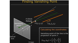
Vanishing point is a point in an image where parallel lines appear to
converge. It is an optical illusion caused by the perspective of the
image. In a two-dimensional image, the vanishing point is the point at
which all parallel lines appear to converge. In a three-dimensional
image, the vanishing point is the point at which all parallel lines appear
to converge in the distance. Vanishing points are used to create the
illusion of depth and distance in an image.
9.
Prof Shree Nayarwho is faculty in the Computer Science Department, School of Engineering and Applied Sciences, Columbia
10.
Image Formation withCamera
The diagram below illustrates the image formation process using a camera.
1. Light enters the camera lens and is focused onto the image sensor.
2. The image sensor captures the light and converts it into an electrical signal.
3. The electrical signal is then processed by the camera's processor and converted into a digital image.
4. The digital image is then stored in the camera's memory.
5. The digital image can then be viewed on the camera's display or transferred to a computer for
further processing.
11.
COMPUTER VISION
• Thereare forward problems and inverse (reverse) problems in computer vision. They are defined based on
the direction of inference or computation in a system
Shahkarami, Alireza. (2014). ASSISTED HISTORY MATCHING USING PATTERN RECOGNITION
TECHNOLOGY.
12.
Forward Problem inCV
Forward Problem in Computer Vision:
A forward problem involves predicting the outcome or result based on known inputs and the physical rules
governing the system. These problems are typically well-posed and easier to solve because the inputs and rules are
known and lead to a unique output.
Example:
Rendering in Computer Graphics: Given the 3D geometry of objects, lighting conditions, and material
properties, the goal is to compute the 2D image as it would appear on a screen or camera.
Image Simulation: Simulating how light interacts with surfaces, passes through lenses, and projects onto an
image plane.
Why Forward Problems Are Easier: Forward problems rely on well-established physical models (like radiometry,
optics, and geometry). These processes typically follow deterministic rules, making the problem computationally
straightforward.
13.
Inverse (Reverse) ProblemIn CV
An inverse problem involves working backward to determine the underlying causes or inputs that produced a given result. These problems are
typically ill-posed, meaning there is not enough information to guarantee a unique solution. Assumptions, models, or additional constraints are
often required.
Example:
3D Reconstruction from 2D Images: Inferring the 3D structure of a scene or objects based on one or more 2D images.
Image Segmentation: Determining which parts of an image correspond to different objects or regions.
Pose Estimation: Inferring the position and orientation of objects or people from a single 2D image or a sequence of images.
Scene Understanding: Identifying objects, lighting conditions, or other scene attributes from a single image.
Why Inverse Problems Are Harder:
They are under-constrained: Multiple different inputs can produce the same output (e.g., many 3D scenes can result in the same 2D image).
They often involve uncertainty, occlusions, or noise in the data.
Solutions typically require statistical inference (e.g., Bayesian reasoning) or machine learning models trained on large datasets to "guess" the most
likely solution.