UNIT 1
• ImageFormation
• Human Vision
• Image Formation using Pin Hole Camera Model
• Image Formation using Camera with lens
• Vanishing Points
• Image Transformations
• 2 D :
• Translation
• Euclidean (Rotation + Translation, 2D rigid body motion or 2D Euclidean transformation)
• Similarity (Scaled Rotation)
• Projective (Perspective Transform / Homography)
• Affine
• Stretch/ Squash
• Hierarchy of 2D Coordinate Transforms
• 3 D :
• Translation
• Euclidean (Rotation + Translation, 2D rigid body motion or 2D Euclidean transformation)
• Similarity (Scaled Rotation)
• Projective (3D Perspective Transform / Homography/ Collineation)
• Affine
• Hierarchy of 3D Coordinate Transforms
• Photometric Image Formation
• Lighting
• Reflectance & Shading – Diffuse Reflection, Specular Reflection, Phong Shading, Dichromatic Reflection Model, Global illumination(ray tracing and
radiosity)
• Digital Camera
• Processing stage of modern digital camera
• Sampling & Aliasing
• Color
3.
Human Vision
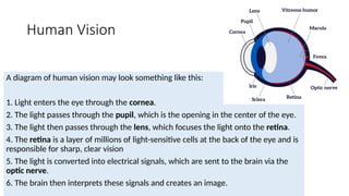
A diagramof human vision may look something like this:
1. Light enters the eye through the cornea.
2. The light passes through the pupil, which is the opening in the center of the eye.
3. The light then passes through the lens, which focuses the light onto the retina.
4. The retina is a layer of millions of light-sensitive cells at the back of the eye and is
responsible for sharp, clear vision
5. The light is converted into electrical signals, which are sent to the brain via the
optic nerve.
6. The brain then interprets these signals and creates an image.
4.
Reference
• Youtube Videos: First Principles of Computer Vision is a
lecture series presented by Shree Nayar who is faculty in the
Computer Science Department, School of Engineering and
Applied Sciences, Columbia University. Computer Vision is
the enterprise of building machines that “see.”
• Text Book: Richard Szeliski
5.
Story of Camera
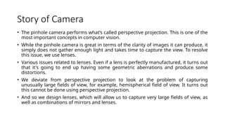
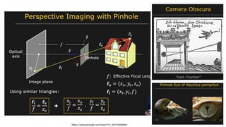
•The pinhole camera performs what’s called perspective projection. This is one of the
most important concepts in computer vision.
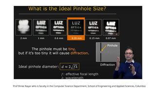
• While the pinhole camera is great in terms of the clarity of images it can produce, it
simply does not gather enough light and takes time to capture the view. To resolve
this issue, we use lenses.
• Various issues related to lenses. Even if a lens is perfectly manufactured, it turns out
that it's going to end up having some geometric aberrations and produce some
distortions.
• We deviate from perspective projection to look at the problem of capturing
unusually large fields of view, for example, hemispherical field of view. It turns out
this cannot be done using perspective projection.
• And so we design lenses, which will allow us to capture very large fields of view, as
well as combinations of mirrors and lenses.
6.
Pin Hole Camera& Perspective Projection
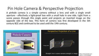
A pinhole camera is a simple camera without a lens and with a single small
aperture - effectively a light-proof box with a small hole in one side. Light from a
scene passes through this single point and projects an inverted image on the
opposite side of the box. This form of camera was first developed in the 5th
century BCE and continued to be used until the 19th century.
https://www.youtube.com/
watch?v=_EhY31MSbNM
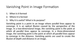
Vanishing Point inImage Formation
1. When is it formed
2. Where it is formed
3. Why it is useful? What is its purpose?
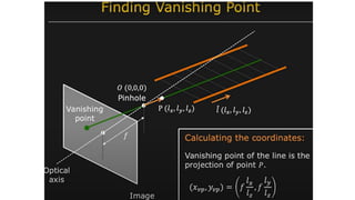
Vanishing point is a point in an image where parallel lines appear to
converge. It is an optical illusion caused by the perspective of the
image. In a two-dimensional image, the vanishing point is the point at
which all parallel lines appear to converge. In a three-dimensional
image, the vanishing point is the point at which all parallel lines appear
to converge in the distance. Vanishing points are used to create the
illusion of depth and distance in an image.
13.
Prof Shree Nayarwho is faculty in the Computer Science Department, School of Engineering and Applied Sciences, Columbia
14.
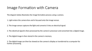
Image Formation withCamera
The diagram below illustrates the image formation process using a camera.
1. Light enters the camera lens and is focused onto the image sensor.
2. The image sensor captures the light and converts it into an electrical signal.
3. The electrical signal is then processed by the camera's processor and converted into a digital image.
4. The digital image is then stored in the camera's memory.
5. The digital image can then be viewed on the camera's display or transferred to a computer for
further processing.
15.
Geometric Primitives
• Geometricprimitives form the basic building blocks used to describe three-
dimensional shapes
• Geometric primitives are basic shapes used in computer graphics. Examples
include points, lines, polygons, circles, ellipses, and rectangles.
• Geometric primitives are basic shapes used to create images. Common
geometric primitives used in image formation include points, lines, circles,
rectangles, polygons, and curves. Points are the smallest unit of an image, and
are used to define the position of other elements. Lines are used to connect
points and create shapes. Circles are used to create round shapes, and
rectangles are used to create squares and rectangles. Polygons are used to
create more complex shapes, and curves are used to create smooth transitions
between points.
16.
Define Mathematically
• 2D Points
• Represented as pixel coordinates
• Represented as homogeneous coordinates, 2D Projective space
• Represented as inhomogeneous coordinates
• 2 D Lines
• Represented as homogeneous coordinates
• Represented as polar coordinates
• Intersection of 2 lines
• Line joining 2 points
• 2 D Conics
• 3 D Points
• Represented as homogeneous coordinates, 2D Projective space
• Represented as inhomogeneous coordinates
• 3 D Lines
• Represented as homogeneous coordinates
• Represented as inhomogeneous coordinates
• 3 D Planes
• Represented as homogeneous coordinates
• Represented as spherical coordinates
• 3 D Quadrics
17.
Sky is theLimit
• https://inst.eecs.berkeley.edu/~cs194-26/fa20/
• https://inst.eecs.berkeley.edu/~cs280/sp18/