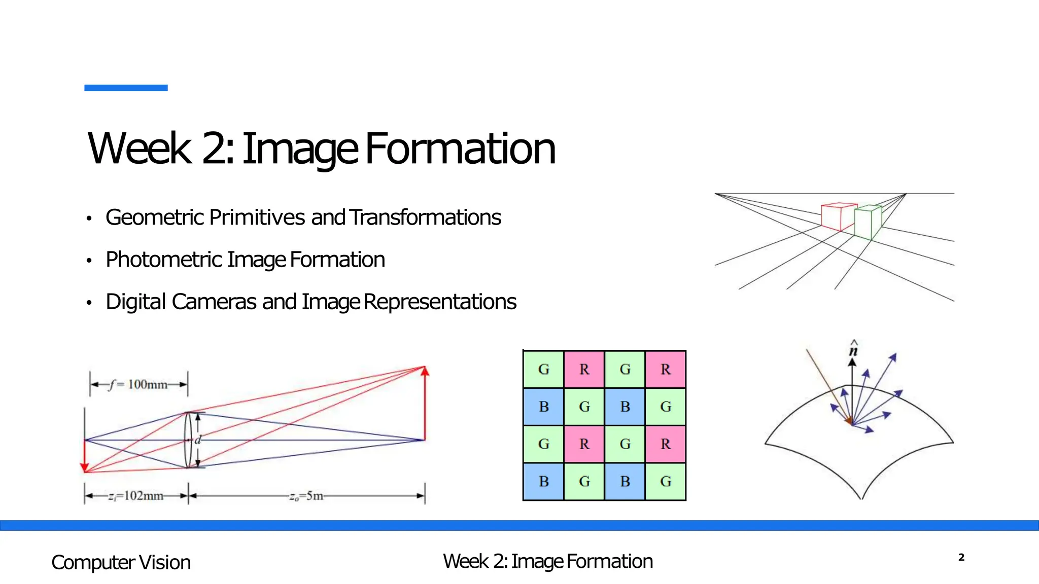
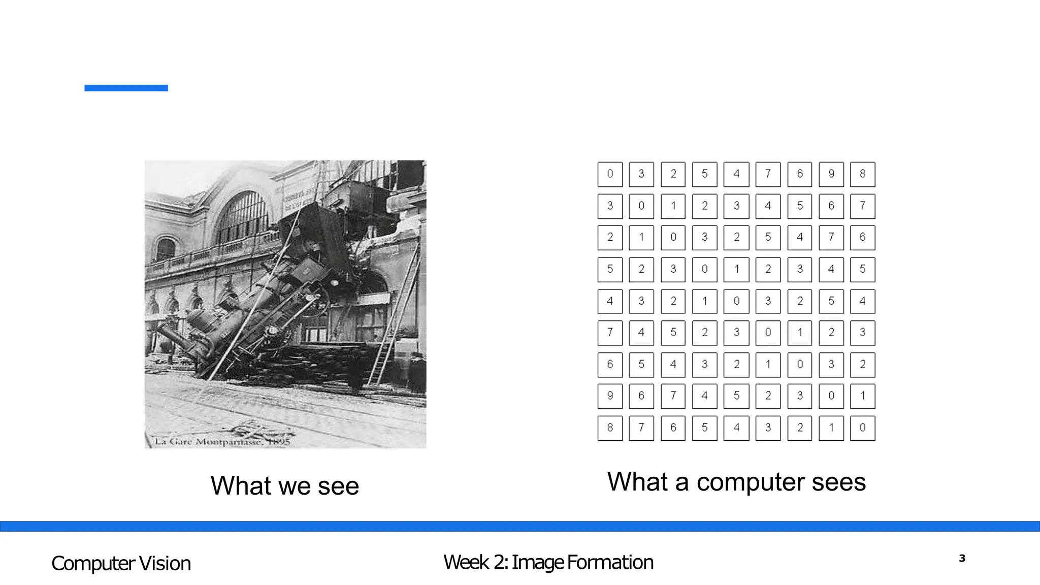
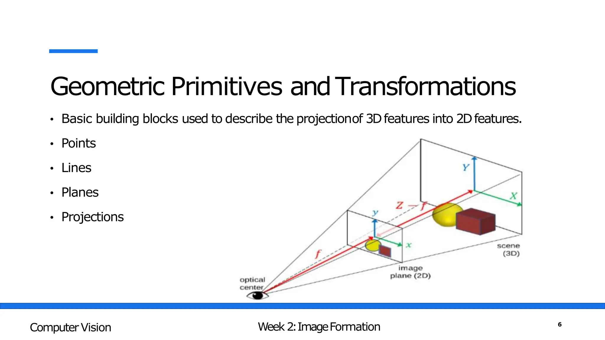
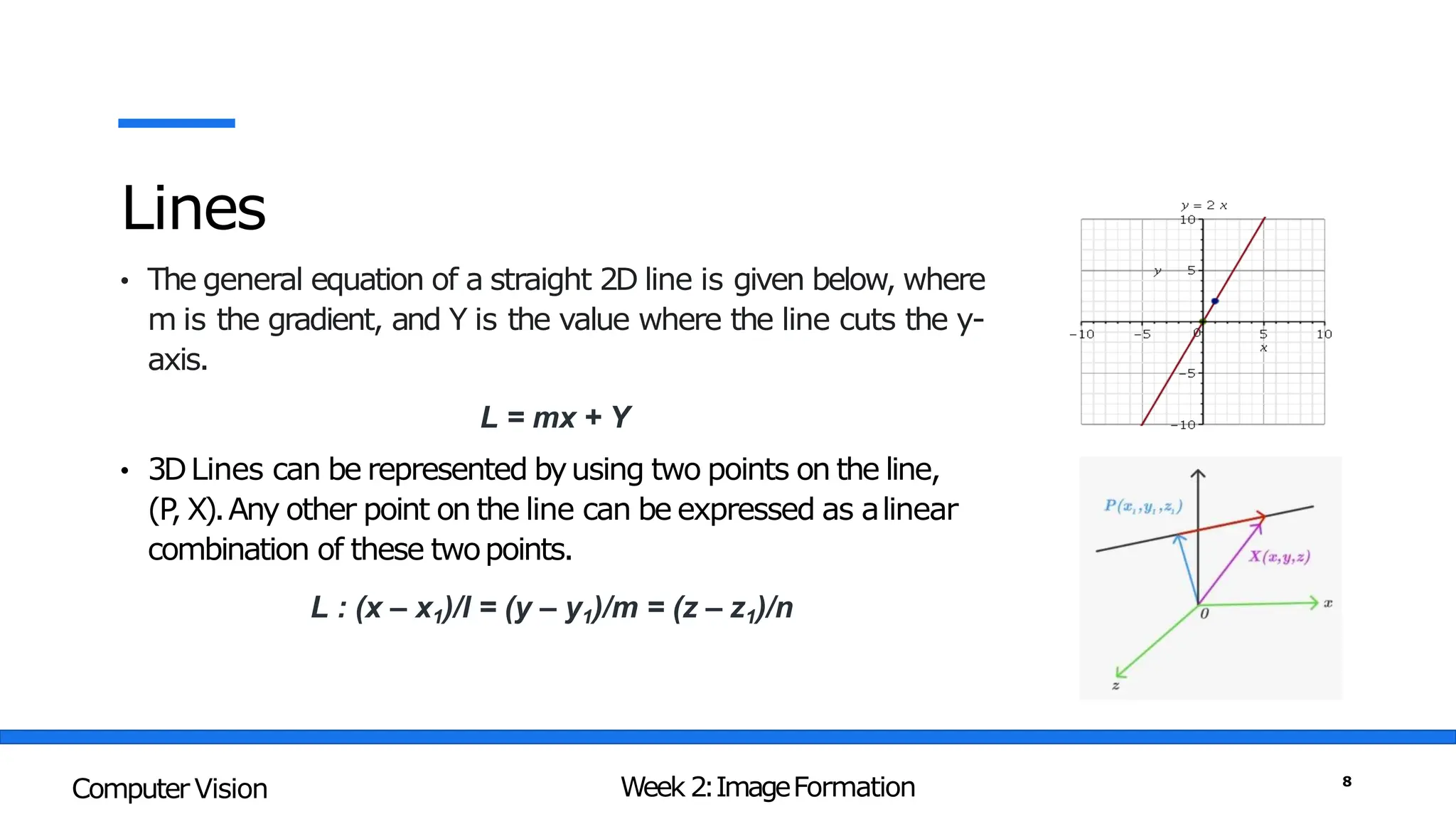
Computer Vision
By:SajidAli
Week 2:ImageFormation
• Geometric Primitives andTransformations
• Photometric ImageFormation
• Digital Cameras and ImageRepresentations
Week 2:ImageFormation
Computer Vision 2
What we see What a computer sees
Week 2:ImageFormation
Computer Vision 3
Computer Vision is Making sense of thesenumbers
255 255 240 255
255 248 232 255
252 247 238 239
255 255 255 255
Week 2:ImageFormation
Computer Vision 4
3Dto 2DConversion implies information loss
graphics
vision
Computer Graphics vs. Computer Vision
Week 2:ImageFormation
Computer Vision 5
Geometric Primitives andTransformations
• Basic building blocks used to describe the projectionof 3Dfeatures into 2Dfeatures.
• Points
• Lines
• Planes
• Projections
Week 2:ImageFormation
Computer Vision 6
Points
• 2Dpoints(pixel coordinates in an image) can be denoted using
a pair of values, x =(x,y)∈ R2 ,or alternatively, a column
vector x ∈ R2x1 :
• 3Dpoints (coordinates in three dimensions) can bewritten
using x =(x,y
,z) ∈ R3
Week 2:ImageFormation
Computer Vision 7
Lines
• The general equation of a straight 2D line is given below, where
m is the gradient, and Y is the value where the line cuts the y-
axis.
L = mx + Y
• 3DLines can be represented byusing two points on the line,
(P
, X).Any other point on the line can be expressed as alinear
combination of these twopoints.
L : (x – x1)/l = (y – y1)/m = (z – z1)/n
Week 2:ImageFormation
Computer Vision 8
3DLines - Proof
Consider a line which passes through the point P(x1, y1, z1),
and has direction vector d⃗=(l, m, n) , where l , m, and n are
non-zero real numbers. Let X=(x, y, z) be a random point on
the line. Then the vector PX ⃗, which is the red arrow in the
figure, will be parallel to d⃗. Hence, we have:
Week 2:ImageFormation
Computer Vision 9
3DLines - Example
Example 1: If a straight line is passing through the two fixed points in the 3-dimensional
plane whose position coordinates are P (2, 3, 5) and Q (4, 6, 12) then find its cartesian
equation using the two-point form.
Solution:
l = (4 – 2), m = (6 – 3), n = (12 – 5)
l = 2, m = 3, n = 7
Choosing the point P (2, 3, 5)
The required equation of the
line
L : (x – 2) / 2 = (y – 3) / 3 = (z – 5) / 7
Week 2:ImageFormation
Computer Vision 10
3DLines - Example
Example 1: If a straight line is passing through the two fixed points in the 3-dimensional
whose position coordinates are X (2, 3, 4) and Y (5, 3, 10) then find its cartesian
equation using the two- point form.
Solution:
l = (5 – 2), m = (3 – 3), n = (10 – 4)
l = 3, m = 0, n = 6
Choosing the point X (2, 3, 4)
The required equation of the
line
L : (x – 2) / 3 = (y – 3) / 0 = (z – 4) / 6
L : (x - 2) / 3 = (z – 4) / 6 and y = 3
Week 2:ImageFormation
Computer Vision 11
ImageFormation in the HumanEye
• When the eye is properly focused, light from an object
outside the eye is imaged on the retina
• Retina consists of two types of light receptors: rodsand
cones
• Rods
Cover all ofretina
75-150 Million
Several rods connected to one optical nerve(low-resolution)
Sensitive to small light intensities (dim-light vision)
Equal response to all colours
Week 2:ImageFormation
Computer Vision 12
ImageFormation in the HumanEye
• Whenthe eye is properly focused, light from an object outside
the eye is imaged on the retina
• Retina consists of two types of light receptors: rodsand
cones
• Cones
Concentrated atfovea
6-7 Million
Onecone connected to one optical nerve(high-resolution)
Sensitive to bright light
(bright-light vision)
Sensitive to colours
Week 2:ImageFormation
Computer Vision 13
ImageFormation in HumanEye
Week 2:ImageFormation
Computer Vision 14
TheElectromagnatic Spectrum
Week 2:ImageFormation
Computer Vision 15
Trichromatic Vision
• Conecells are of three types, each containing a
photosensitive pigment that responds to a
particular wavelength oflight
• S-cones are sensitive to “short”wavelengths,
corresponding to the bluecolour
• M-cones are sensitive to “medium”wavelengths,
corresponding to the greencolour
• L-cones are sensitive to “long”wavelengths,
corresponding to the redcolour
Week 2:ImageFormation
Computer Vision 16
Capturing Images
• Pinhole Cameras
• Lenses
• Digital Cameras
The first photograph on record, “la table
servie”, obtained by Nicephore Niepce in
1822
Week 2:ImageFormation
Computer Vision 17
Pinhole Camera
Week 2:ImageFormation
Computer Vision 18
Pinhole Perspective
Week 2:ImageFormation
Computer Vision 19
Pinhole Perspective
Week 2:ImageFormation
Computer Vision 20
Introducing Lens
• Smaller the pinhole sharper the
images but also darker
• Larger the pinhole brighterthe
image but also more blurry
• Most cameras use a converginglens
to allow light to enter thedevice.
• Zoomlenses found in cameras
utilize a combination of convex and
concave lenses to producedifferent
types of images.
Week 2:ImageFormation
Computer Vision 21
Reflection
• Incident light is reflected intwo main
forms
1. Diffuse reflection: light scattered
isotropically in all directions(shows
true colour of theobject)
2. Specular reflection: Incident light
reflected in a specific direction
(mirror-like effect)
• Most materials exhibit a mixtureof
diffuse and specular reflections
Week 2:ImageFormation
Computer Vision 22
Thin Lens Phenomena
The thin lens equation defines the
relationship between the focal length of a
lens, the distance of an object from that
lens, and the distance of the image formed
by the lens.
Week 2:ImageFormation
Computer Vision 23
Focal Length of aLens
Week 2:ImageFormation
Computer Vision 24
Focal Length
Focallength,usuallyrepresentedinmillimeters
(mm).
I
tis a calculationofan opticaldistancefromthepoint where
lightraysconvergeto forma sharpimage ofan objecttothe
digitalsensorat the focalplaneinthecamera.
Thefocallengthofalensis determinedwhenthelens
is focusedat infinity.
Lensfocallengthtellsustheangleofview—howmuchofthe
scenewillbecaptured—andthemagnification—howlarge
individualelementswill be.
Thelongerthefocallength,thenarrowertheangleof
viewandthehigherthe magnification.
Theshorterthefocallength,thewidertheangleof
viewandthelowerthe magnification.
Week 2:ImageFormation
Computer Vision 25
Digital Cameras
• Imagesensing
pipeline,
• Various sources of
noise
• Typical digital post-
processing steps
Week 2:ImageFormation
Computer Vision 26
Capturing Digital Images
• Light falling on an imaging sensor is
usually picked upbyan active sensing
area
• Charge-Coupled Device(CCD)
• Complementary Metal Oxide on Silicon
(CMOS)
• CCDs are prone to“Blooming”
• CCD sensors outperformed CMOSin
quality-sensitive applications
Week 2:ImageFormation
Computer Vision 27
Digital Cameras – ImageSensing
Week 2:ImageFormation
Computer Vision 28
Digital Camera – ImageFormation
Week 2:ImageFormation
Computer Vision 29
Sampling and Quantization
Week 2:ImageFormation
Computer Vision 30
Continuous ImageProjected onto a Sensor Array
Week 2:ImageFormation
Computer Vision 31
Image formation is an analog
to digital conversion of an
image with the help of 2D
Sampling and Quantization
techniques that is done by the
capturing devices like
cameras.
Week 2:ImageFormation
Computer Vision 32
Sampling
• Sampling is a spatial
resolutionof the digital
image.
• Therate of sampling
determines the qualityof
the digitized image.
Week 2:ImageFormation
Computer Vision 33
Spatial Resolution
• Thespatial resolution of an image is
determined byhow sampling was carried
out.
• There are 3measures which we see often
relating to ImageSize/Resolution
a. Pixelcount- e.g.,3000x2000pixels
b. Physicalsize- e.g.,8"x10"
c. Resolution- e.g.,240pixelsperinch(PPI)
Week 2:ImageFormation
Computer Vision 34
Quantization
• Thetransitionofthecontinuousvalues
fromtheimagefunctiontoitsdigital
equivalentis called quantization.
• Quantizationis thenumberofgreylevels
inthedigitalimage.
• I
tis relatedtotheintensityvaluesofthe
image.
• 8-bitquantization:28=
2
5
6graylevels
(0:black,255:white)
• 1-bitquantization:2graylevels
(0:black,1:white)–binary
Week 2:ImageFormation
Computer Vision 35
Intensity Resolution
• Intensitylevelresolutionrefersto
thenumberofintensitylevelsused
torepresenttheimage
• Themoreintensitylevelsused,the
finerthelevelofdetailinanimage
• Intensitylevelresolutionis usually
givenintermsofthenumberofbits
usedtostoreeachintensitylevel
Week 2:ImageFormation
Computer Vision 36
Resolution:HowMuchisEnough?
Week 2:ImageFormation
Computer Vision 37
DigitalImageis anapproximationofarealworldscene
Week 2:ImageFormation
Computer Vision 38
Image Representations
Imageis a collection of light intensities at different locations.
Week 2:ImageFormation
Computer Vision 39
Image Representations
Pixel – Building Block of DigitalImage
Week 2:ImageFormation
Computer Vision 40
Image Representations
Week 2:ImageFormation
Computer Vision 41
RGB Images
Week 2:ImageFormation
Computer Vision 42
RGB Images vs Grey Scale Images
Week 2:ImageFormation
Computer Vision 43
Binary vs. Grey-Scale vs. RGB Images
Week 2:ImageFormation
Computer Vision 44
Factors Affecting Performance of DigitalCameras
• Shutter Speed – Under exposed vs Over-Exposed
Week 2:ImageFormation
Computer Vision 45
Factors Affecting Performance of DigitalCameras
• Sampling Pitch - Physical spacing between adjacent sensor cells
Week 2:ImageFormation
Computer Vision 46
Factors Affecting Performance of DigitalCameras
• Fill Factor - active sensing area size as a fraction of the theoretically available sensing area
Week 2:ImageFormation
Computer Vision 47
Factors Affecting Performance of DigitalCameras
• Chip Size- having a larger chip size is preferable, since each sensor cell can be more photo-
sensitive
• Analog Gain - a higher gain allows the camera to perform better under low light conditions
(less motion blur due to long exposure times when the aperture isalready maxed out).
• Sensor Noise - noise is added from various sources, which may include fixed pattern noise,
dark current noise, shot noise, amplifier noise, and quantizationnoise
• ADC Resolution - how many bits it yields and its noise level (how manyof these bits are useful
in practice)
Week 2:ImageFormation
Computer Vision 48

Computer Vision - Image Formation.pptx

  • 1.
  • 2.
    Week 2:ImageFormation • GeometricPrimitives andTransformations • Photometric ImageFormation • Digital Cameras and ImageRepresentations Week 2:ImageFormation Computer Vision 2
  • 3.
    What we seeWhat a computer sees Week 2:ImageFormation Computer Vision 3
  • 4.
    Computer Vision isMaking sense of thesenumbers 255 255 240 255 255 248 232 255 252 247 238 239 255 255 255 255 Week 2:ImageFormation Computer Vision 4
  • 5.
    3Dto 2DConversion impliesinformation loss graphics vision Computer Graphics vs. Computer Vision Week 2:ImageFormation Computer Vision 5
  • 6.
    Geometric Primitives andTransformations •Basic building blocks used to describe the projectionof 3Dfeatures into 2Dfeatures. • Points • Lines • Planes • Projections Week 2:ImageFormation Computer Vision 6
  • 7.
    Points • 2Dpoints(pixel coordinatesin an image) can be denoted using a pair of values, x =(x,y)∈ R2 ,or alternatively, a column vector x ∈ R2x1 : • 3Dpoints (coordinates in three dimensions) can bewritten using x =(x,y ,z) ∈ R3 Week 2:ImageFormation Computer Vision 7
  • 8.
    Lines • The generalequation of a straight 2D line is given below, where m is the gradient, and Y is the value where the line cuts the y- axis. L = mx + Y • 3DLines can be represented byusing two points on the line, (P , X).Any other point on the line can be expressed as alinear combination of these twopoints. L : (x – x1)/l = (y – y1)/m = (z – z1)/n Week 2:ImageFormation Computer Vision 8
  • 9.
    3DLines - Proof Considera line which passes through the point P(x1, y1, z1), and has direction vector d⃗=(l, m, n) , where l , m, and n are non-zero real numbers. Let X=(x, y, z) be a random point on the line. Then the vector PX ⃗, which is the red arrow in the figure, will be parallel to d⃗. Hence, we have: Week 2:ImageFormation Computer Vision 9
  • 10.
    3DLines - Example Example1: If a straight line is passing through the two fixed points in the 3-dimensional plane whose position coordinates are P (2, 3, 5) and Q (4, 6, 12) then find its cartesian equation using the two-point form. Solution: l = (4 – 2), m = (6 – 3), n = (12 – 5) l = 2, m = 3, n = 7 Choosing the point P (2, 3, 5) The required equation of the line L : (x – 2) / 2 = (y – 3) / 3 = (z – 5) / 7 Week 2:ImageFormation Computer Vision 10
  • 11.
    3DLines - Example Example1: If a straight line is passing through the two fixed points in the 3-dimensional whose position coordinates are X (2, 3, 4) and Y (5, 3, 10) then find its cartesian equation using the two- point form. Solution: l = (5 – 2), m = (3 – 3), n = (10 – 4) l = 3, m = 0, n = 6 Choosing the point X (2, 3, 4) The required equation of the line L : (x – 2) / 3 = (y – 3) / 0 = (z – 4) / 6 L : (x - 2) / 3 = (z – 4) / 6 and y = 3 Week 2:ImageFormation Computer Vision 11
  • 12.
    ImageFormation in theHumanEye • When the eye is properly focused, light from an object outside the eye is imaged on the retina • Retina consists of two types of light receptors: rodsand cones • Rods Cover all ofretina 75-150 Million Several rods connected to one optical nerve(low-resolution) Sensitive to small light intensities (dim-light vision) Equal response to all colours Week 2:ImageFormation Computer Vision 12
  • 13.
    ImageFormation in theHumanEye • Whenthe eye is properly focused, light from an object outside the eye is imaged on the retina • Retina consists of two types of light receptors: rodsand cones • Cones Concentrated atfovea 6-7 Million Onecone connected to one optical nerve(high-resolution) Sensitive to bright light (bright-light vision) Sensitive to colours Week 2:ImageFormation Computer Vision 13
  • 14.
    ImageFormation in HumanEye Week2:ImageFormation Computer Vision 14
  • 15.
  • 16.
    Trichromatic Vision • Conecellsare of three types, each containing a photosensitive pigment that responds to a particular wavelength oflight • S-cones are sensitive to “short”wavelengths, corresponding to the bluecolour • M-cones are sensitive to “medium”wavelengths, corresponding to the greencolour • L-cones are sensitive to “long”wavelengths, corresponding to the redcolour Week 2:ImageFormation Computer Vision 16
  • 17.
    Capturing Images • PinholeCameras • Lenses • Digital Cameras The first photograph on record, “la table servie”, obtained by Nicephore Niepce in 1822 Week 2:ImageFormation Computer Vision 17
  • 18.
  • 19.
  • 20.
  • 21.
    Introducing Lens • Smallerthe pinhole sharper the images but also darker • Larger the pinhole brighterthe image but also more blurry • Most cameras use a converginglens to allow light to enter thedevice. • Zoomlenses found in cameras utilize a combination of convex and concave lenses to producedifferent types of images. Week 2:ImageFormation Computer Vision 21
  • 22.
    Reflection • Incident lightis reflected intwo main forms 1. Diffuse reflection: light scattered isotropically in all directions(shows true colour of theobject) 2. Specular reflection: Incident light reflected in a specific direction (mirror-like effect) • Most materials exhibit a mixtureof diffuse and specular reflections Week 2:ImageFormation Computer Vision 22
  • 23.
    Thin Lens Phenomena Thethin lens equation defines the relationship between the focal length of a lens, the distance of an object from that lens, and the distance of the image formed by the lens. Week 2:ImageFormation Computer Vision 23
  • 24.
    Focal Length ofaLens Week 2:ImageFormation Computer Vision 24
  • 25.
    Focal Length Focallength,usuallyrepresentedinmillimeters (mm). I tis acalculationofan opticaldistancefromthepoint where lightraysconvergeto forma sharpimage ofan objecttothe digitalsensorat the focalplaneinthecamera. Thefocallengthofalensis determinedwhenthelens is focusedat infinity. Lensfocallengthtellsustheangleofview—howmuchofthe scenewillbecaptured—andthemagnification—howlarge individualelementswill be. Thelongerthefocallength,thenarrowertheangleof viewandthehigherthe magnification. Theshorterthefocallength,thewidertheangleof viewandthelowerthe magnification. Week 2:ImageFormation Computer Vision 25
  • 26.
    Digital Cameras • Imagesensing pipeline, •Various sources of noise • Typical digital post- processing steps Week 2:ImageFormation Computer Vision 26
  • 27.
    Capturing Digital Images •Light falling on an imaging sensor is usually picked upbyan active sensing area • Charge-Coupled Device(CCD) • Complementary Metal Oxide on Silicon (CMOS) • CCDs are prone to“Blooming” • CCD sensors outperformed CMOSin quality-sensitive applications Week 2:ImageFormation Computer Vision 27
  • 28.
    Digital Cameras –ImageSensing Week 2:ImageFormation Computer Vision 28
  • 29.
    Digital Camera –ImageFormation Week 2:ImageFormation Computer Vision 29
  • 30.
    Sampling and Quantization Week2:ImageFormation Computer Vision 30
  • 31.
    Continuous ImageProjected ontoa Sensor Array Week 2:ImageFormation Computer Vision 31
  • 32.
    Image formation isan analog to digital conversion of an image with the help of 2D Sampling and Quantization techniques that is done by the capturing devices like cameras. Week 2:ImageFormation Computer Vision 32
  • 33.
    Sampling • Sampling isa spatial resolutionof the digital image. • Therate of sampling determines the qualityof the digitized image. Week 2:ImageFormation Computer Vision 33
  • 34.
    Spatial Resolution • Thespatialresolution of an image is determined byhow sampling was carried out. • There are 3measures which we see often relating to ImageSize/Resolution a. Pixelcount- e.g.,3000x2000pixels b. Physicalsize- e.g.,8"x10" c. Resolution- e.g.,240pixelsperinch(PPI) Week 2:ImageFormation Computer Vision 34
  • 35.
    Quantization • Thetransitionofthecontinuousvalues fromtheimagefunctiontoitsdigital equivalentis calledquantization. • Quantizationis thenumberofgreylevels inthedigitalimage. • I tis relatedtotheintensityvaluesofthe image. • 8-bitquantization:28= 2 5 6graylevels (0:black,255:white) • 1-bitquantization:2graylevels (0:black,1:white)–binary Week 2:ImageFormation Computer Vision 35
  • 36.
    Intensity Resolution • Intensitylevelresolutionrefersto thenumberofintensitylevelsused torepresenttheimage •Themoreintensitylevelsused,the finerthelevelofdetailinanimage • Intensitylevelresolutionis usually givenintermsofthenumberofbits usedtostoreeachintensitylevel Week 2:ImageFormation Computer Vision 36
  • 37.
  • 38.
  • 39.
    Image Representations Imageis acollection of light intensities at different locations. Week 2:ImageFormation Computer Vision 39
  • 40.
    Image Representations Pixel –Building Block of DigitalImage Week 2:ImageFormation Computer Vision 40
  • 41.
  • 42.
  • 43.
    RGB Images vsGrey Scale Images Week 2:ImageFormation Computer Vision 43
  • 44.
    Binary vs. Grey-Scalevs. RGB Images Week 2:ImageFormation Computer Vision 44
  • 45.
    Factors Affecting Performanceof DigitalCameras • Shutter Speed – Under exposed vs Over-Exposed Week 2:ImageFormation Computer Vision 45
  • 46.
    Factors Affecting Performanceof DigitalCameras • Sampling Pitch - Physical spacing between adjacent sensor cells Week 2:ImageFormation Computer Vision 46
  • 47.
    Factors Affecting Performanceof DigitalCameras • Fill Factor - active sensing area size as a fraction of the theoretically available sensing area Week 2:ImageFormation Computer Vision 47
  • 48.
    Factors Affecting Performanceof DigitalCameras • Chip Size- having a larger chip size is preferable, since each sensor cell can be more photo- sensitive • Analog Gain - a higher gain allows the camera to perform better under low light conditions (less motion blur due to long exposure times when the aperture isalready maxed out). • Sensor Noise - noise is added from various sources, which may include fixed pattern noise, dark current noise, shot noise, amplifier noise, and quantizationnoise • ADC Resolution - how many bits it yields and its noise level (how manyof these bits are useful in practice) Week 2:ImageFormation Computer Vision 48