3
Image Formation
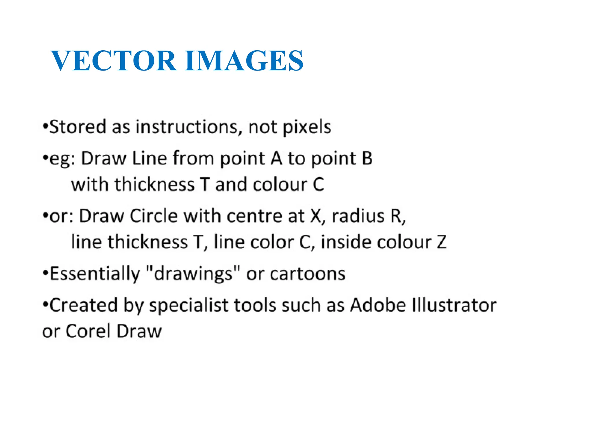
•In computergraphics, we form images
which are generally two dimensional using
a process analogous to how images are
formed by physical imaging systems
Cameras
Microscopes
Telescopes
Human visual system
4.
4
Elements of ImageFormation
•Objects
•Viewer
•Light source(s)
•Attributes that govern how light interacts
with the materials in the scene
•Note the independence of the objects, the
viewer, and the light source(s)
5.
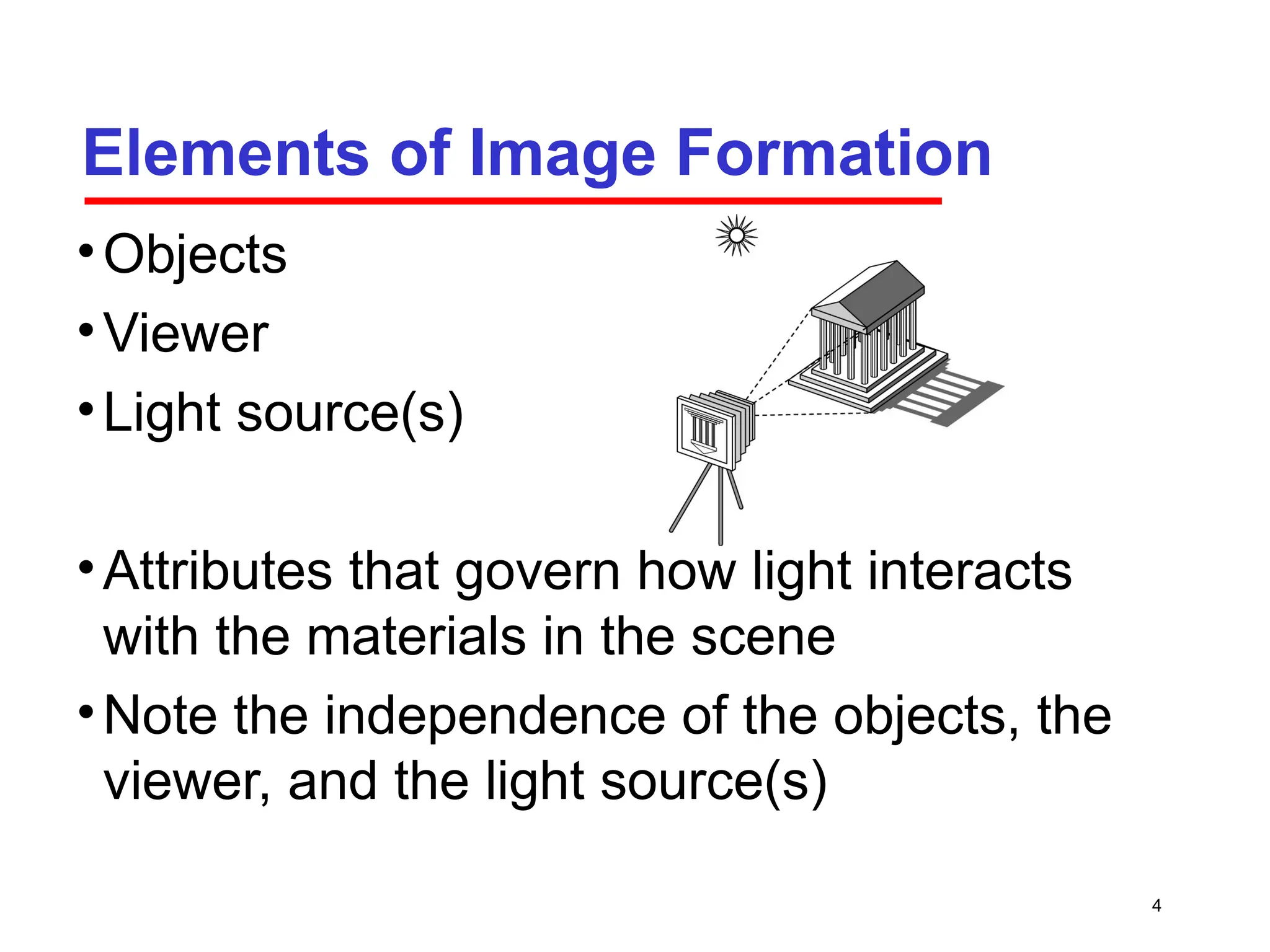
Pinhole Lens
Light (Energy)Source
Surface
Imaging Plane
World Optics Sensor Signal
B&W Film
Color Film
TV Camera
Silver Density
Silver density
in three color
layers
Electrical
6.
6
Light
•Light is thepart of the electromagnetic
spectrum that causes a reaction in our
visual systems
•Generally these are wavelengths in the
range of about 350-750 nm (nanometers)
•Long wavelengths appear as reds and
short wavelengths as blues
7.
7
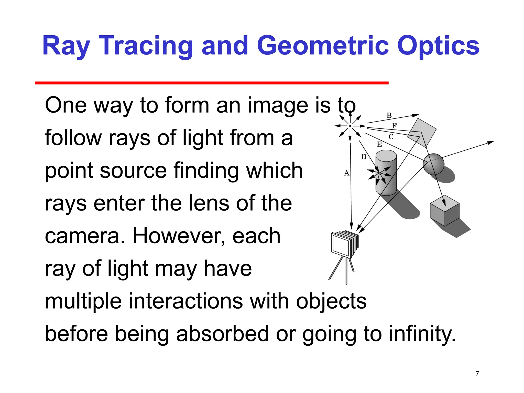
Ray Tracing andGeometric Optics
One way to form an image is to
follow rays of light from a
point source finding which
rays enter the lens of the
camera. However, each
ray of light may have
multiple interactions with objects
before being absorbed or going to infinity.
8.
8
Luminance and ColorImages
•Luminance Image
Monochromatic
Values are gray levels
Analogous to working with black and white film
or television
•Color Image
Has perceptional attributes of hue, saturation,
and lightness.
9.
9
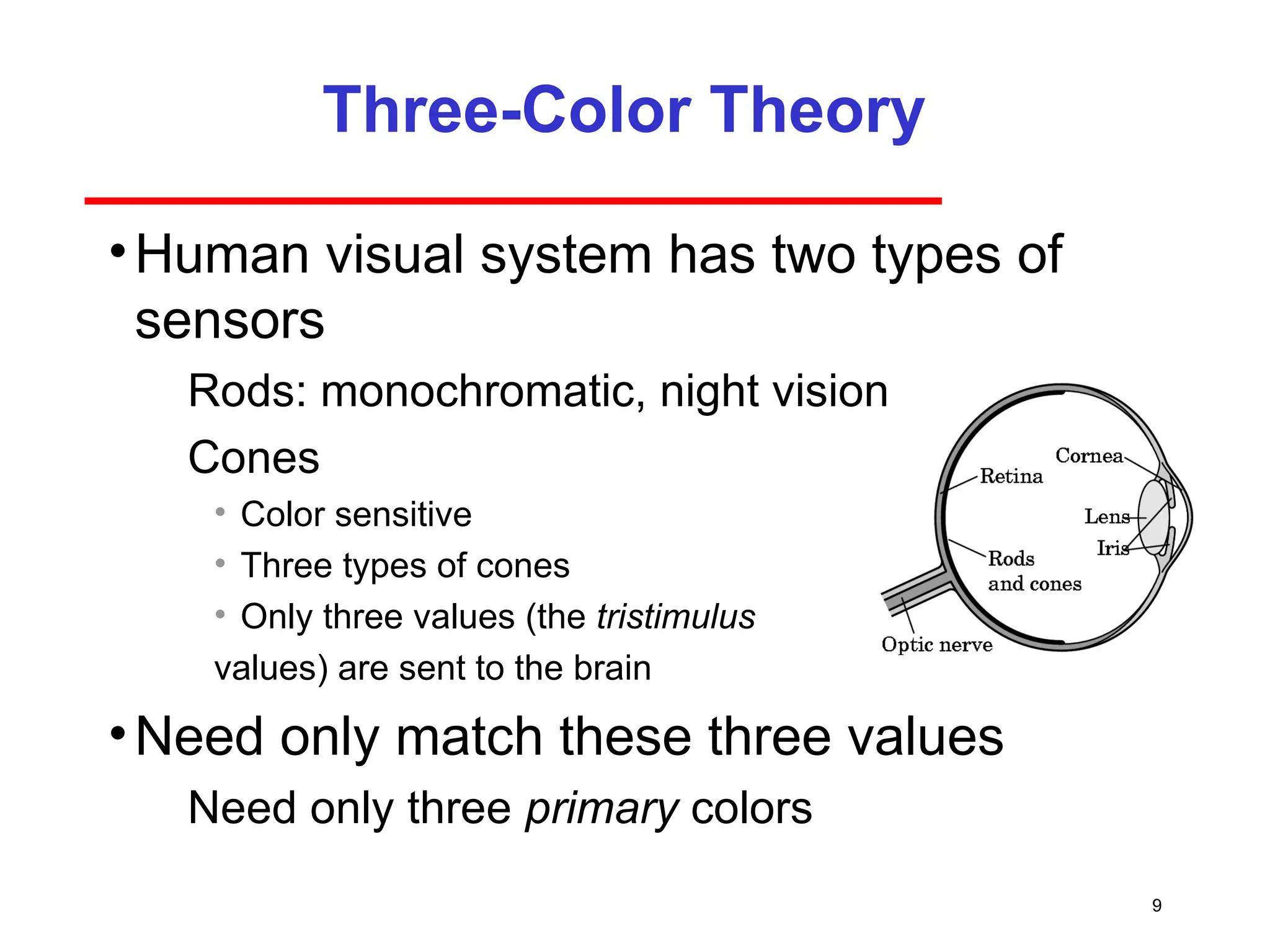
Three-Color Theory
•Human visualsystem has two types of
sensors
Rods: monochromatic, night vision
Cones
• Color sensitive
• Three types of cones
• Only three values (the tristimulus
values) are sent to the brain
•Need only match these three values
Need only three primary colors
10.
10
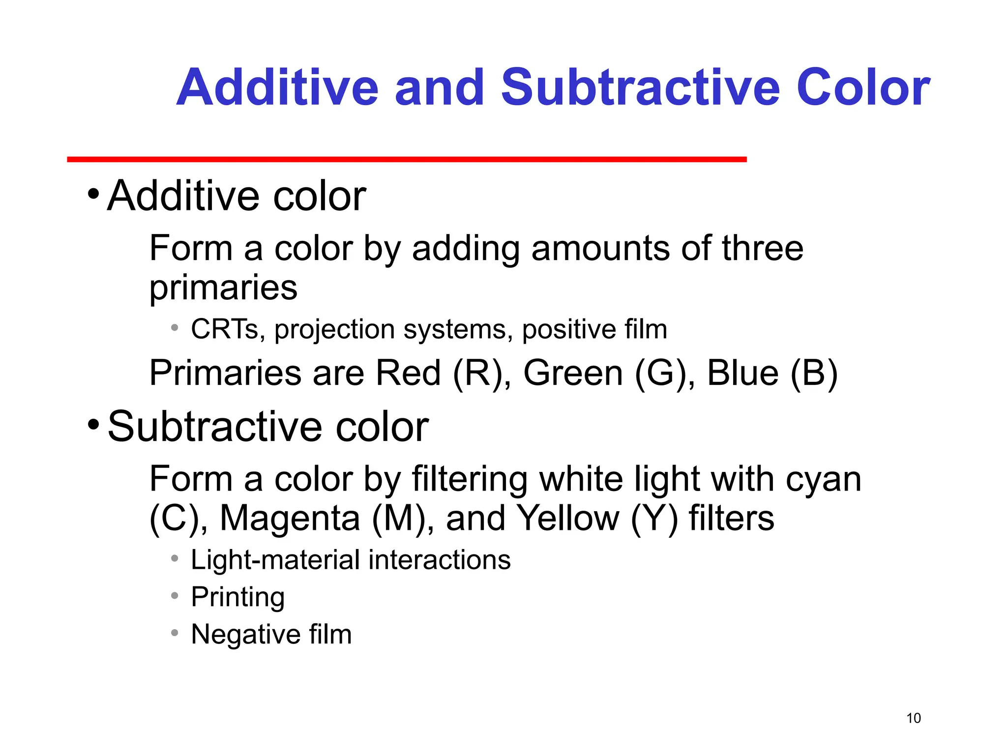
Additive and SubtractiveColor
•Additive color
Form a color by adding amounts of three
primaries
• CRTs, projection systems, positive film
Primaries are Red (R), Green (G), Blue (B)
•Subtractive color
Form a color by filtering white light with cyan
(C), Magenta (M), and Yellow (Y) filters
• Light-material interactions
• Printing
• Negative film
11.
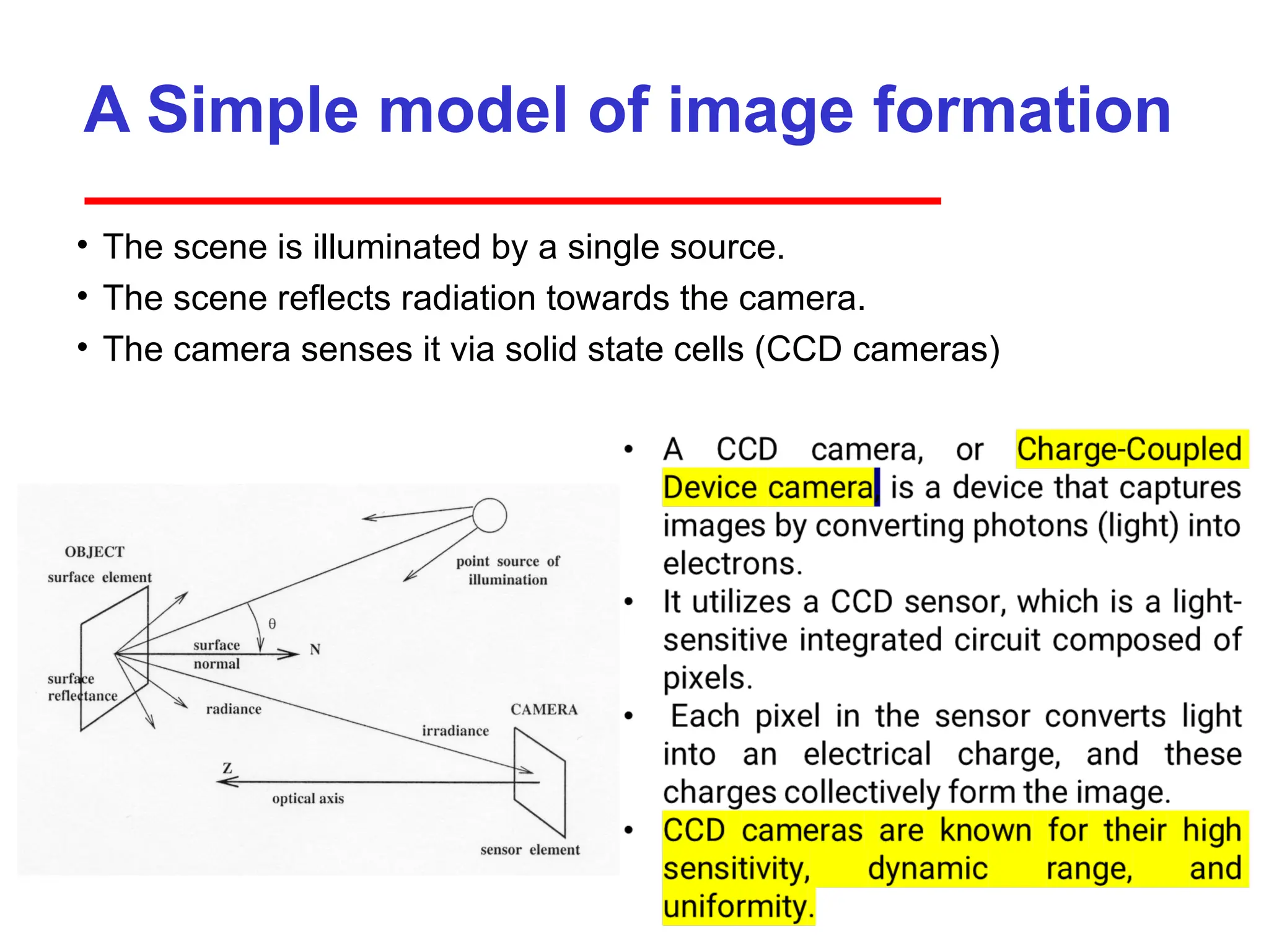
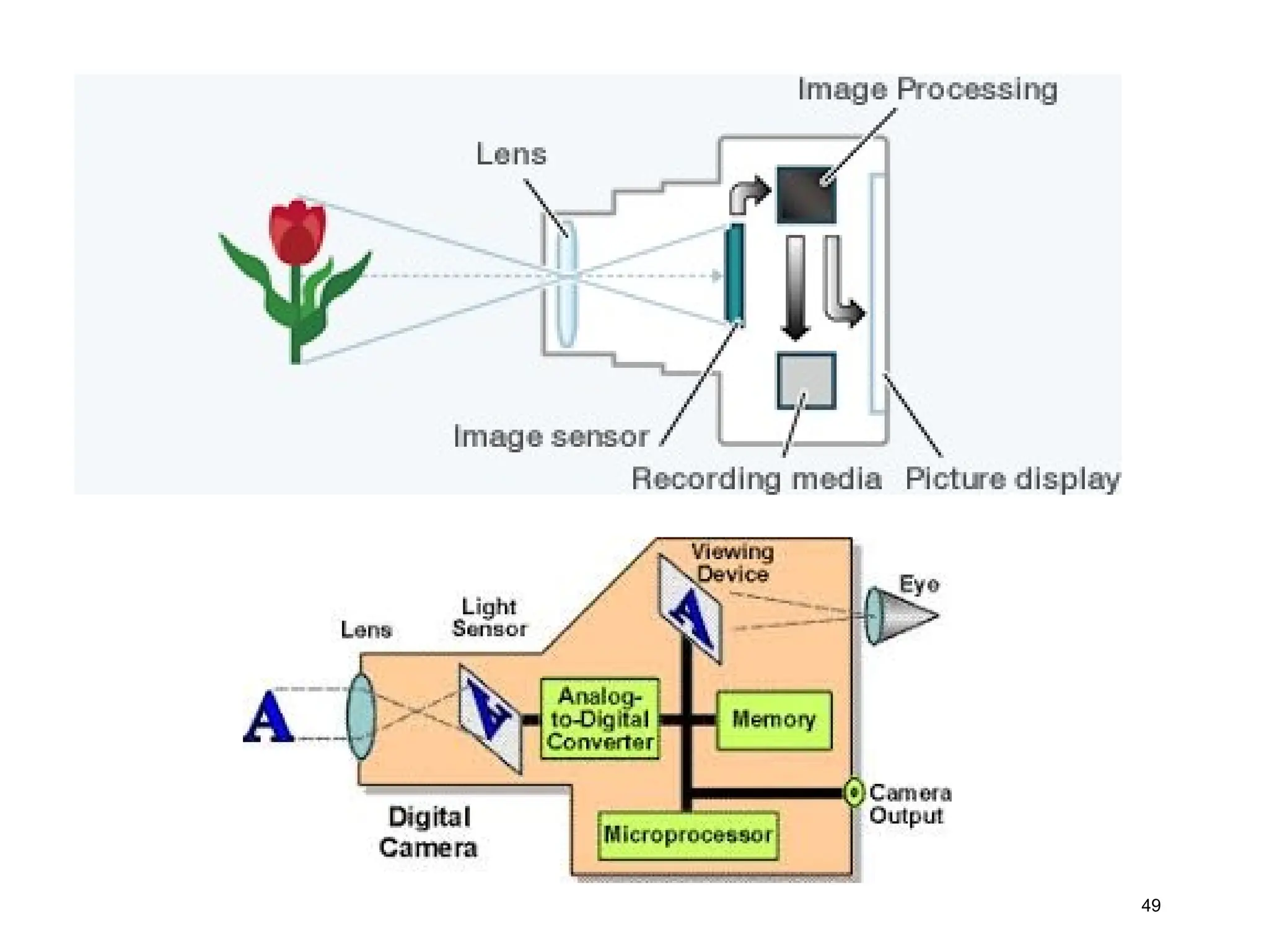
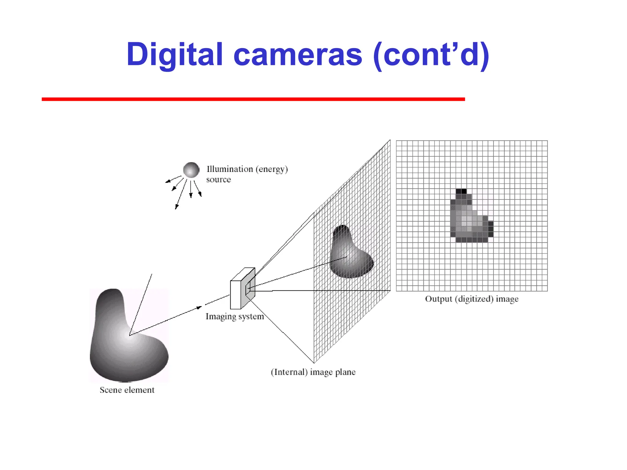
A Simple modelof image formation
• The scene is illuminated by a single source.
• The scene reflects radiation towards the camera.
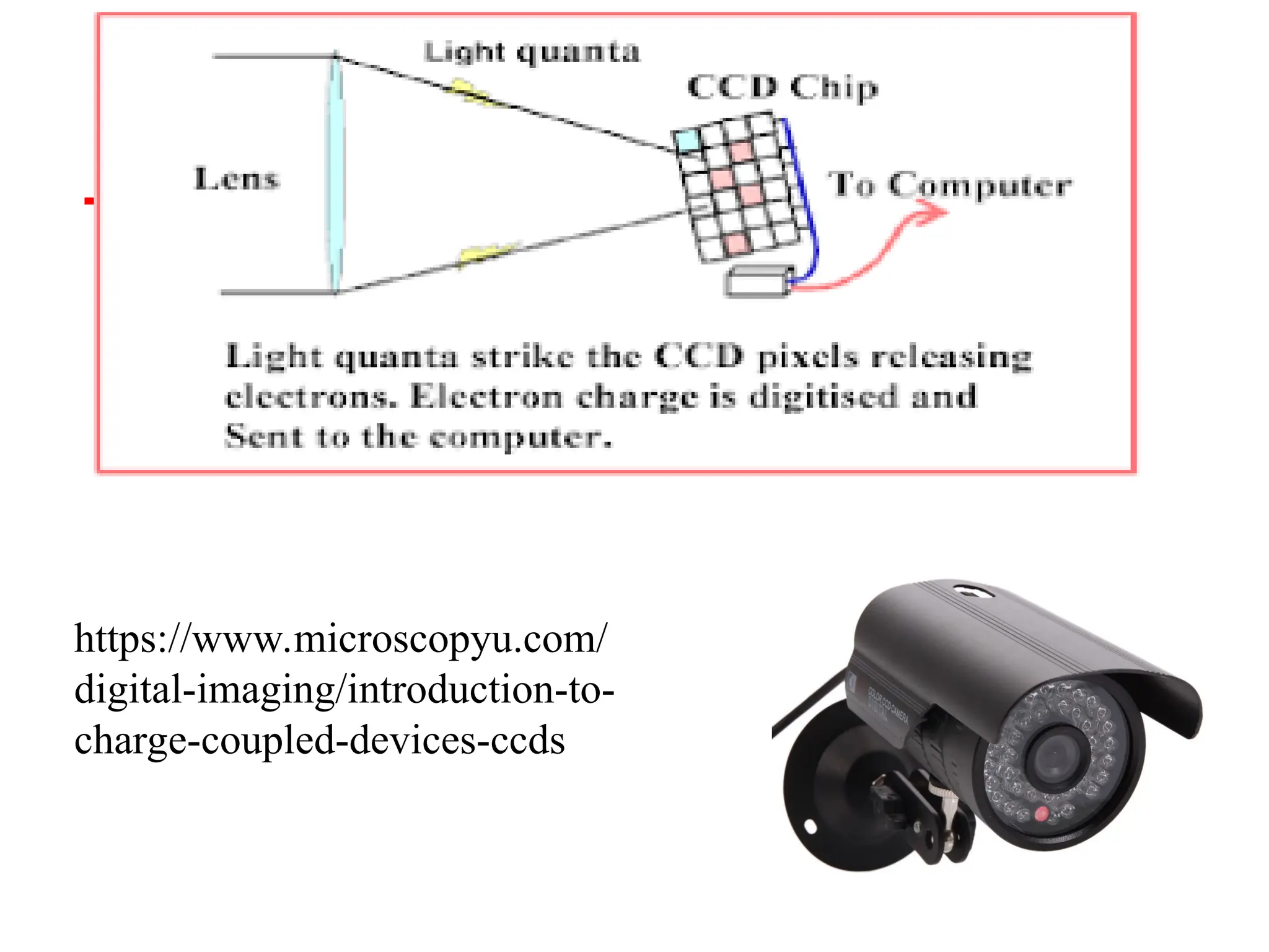
• The camera senses it via solid state cells (CCD cameras)
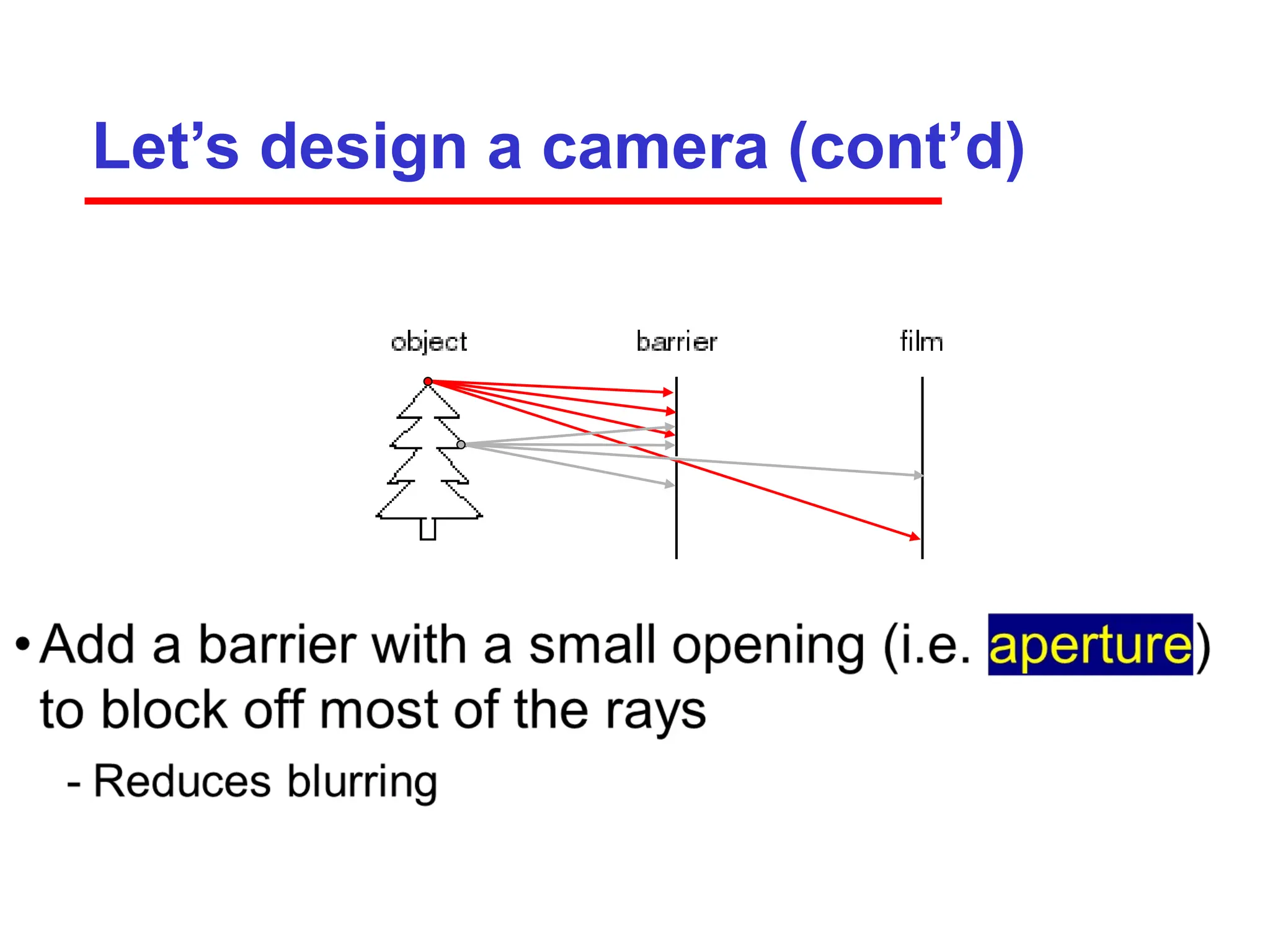
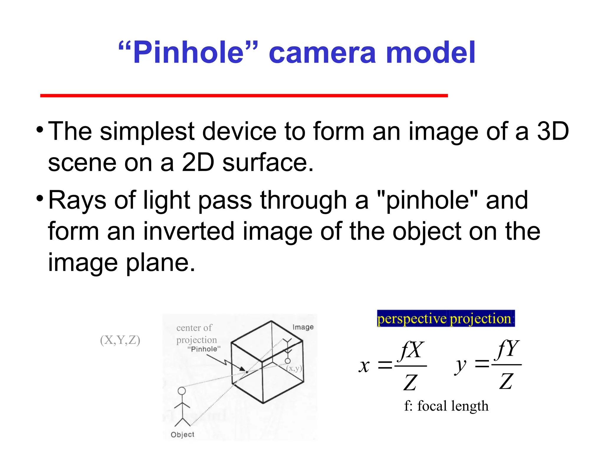
“Pinhole” camera model
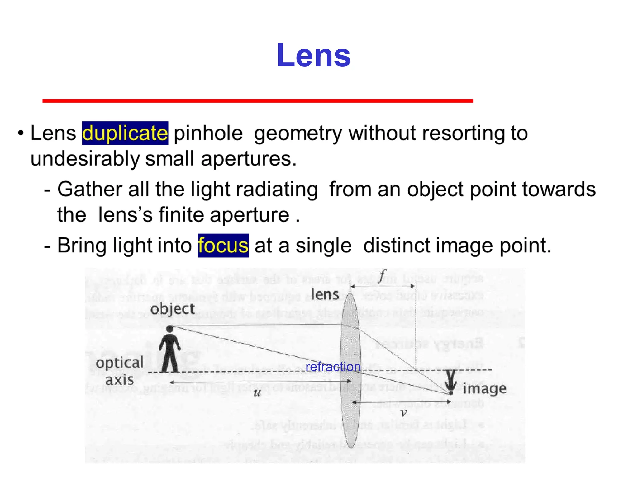
•Thesimplest device to form an image of a 3D
scene on a 2D surface.
•Rays of light pass through a "pinhole" and
form an inverted image of the object on the
image plane.
center of
projection
(x,y)
(X,Y,Z)
f: focal length
fX
x
Z
fY
y
Z
16.
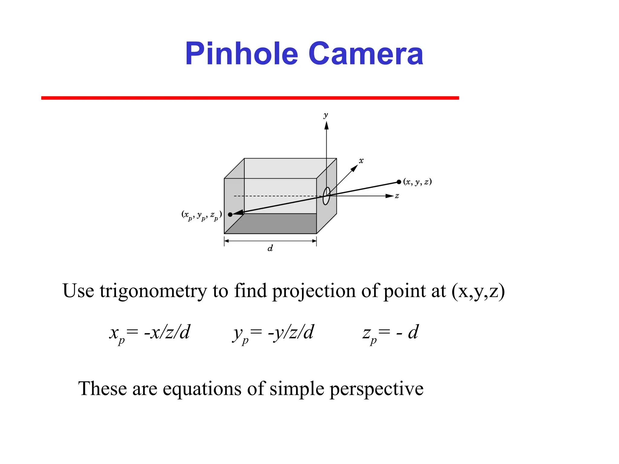
Pinhole Camera
xp= -x/z/dyp= -y/z/d
Use trigonometry to find projection of point at (x,y,z)
These are equations of simple perspective
zp= - d
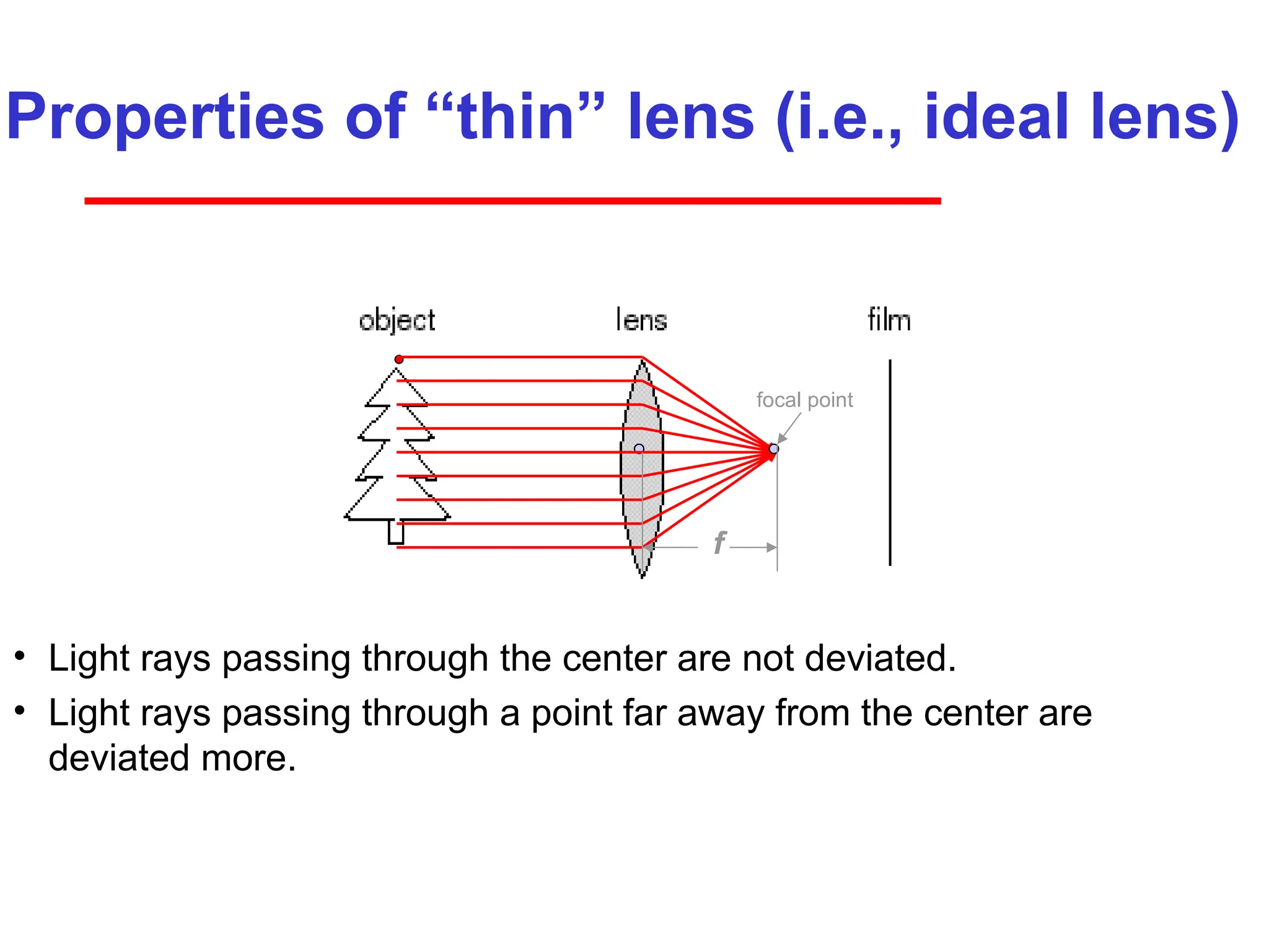
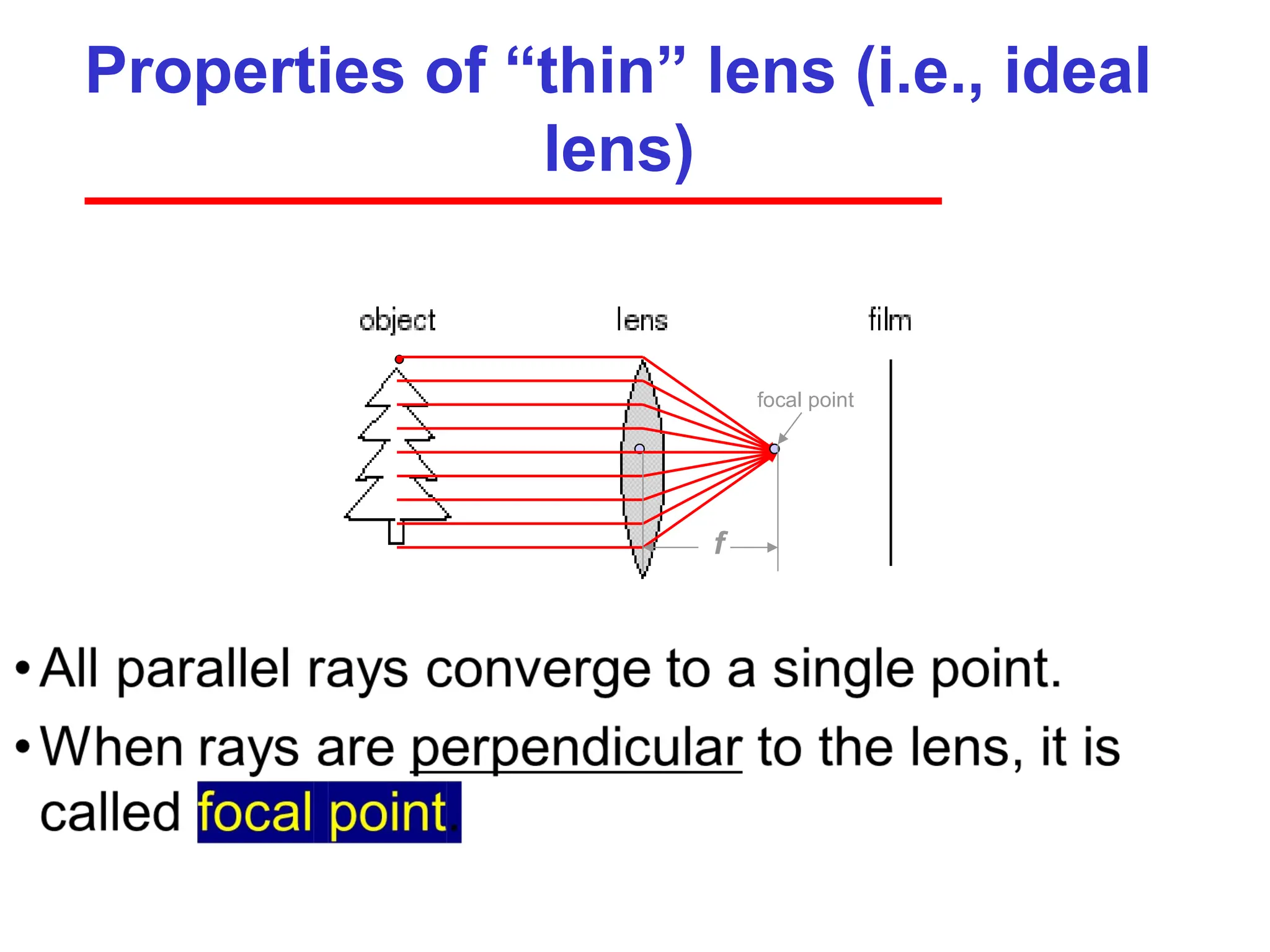
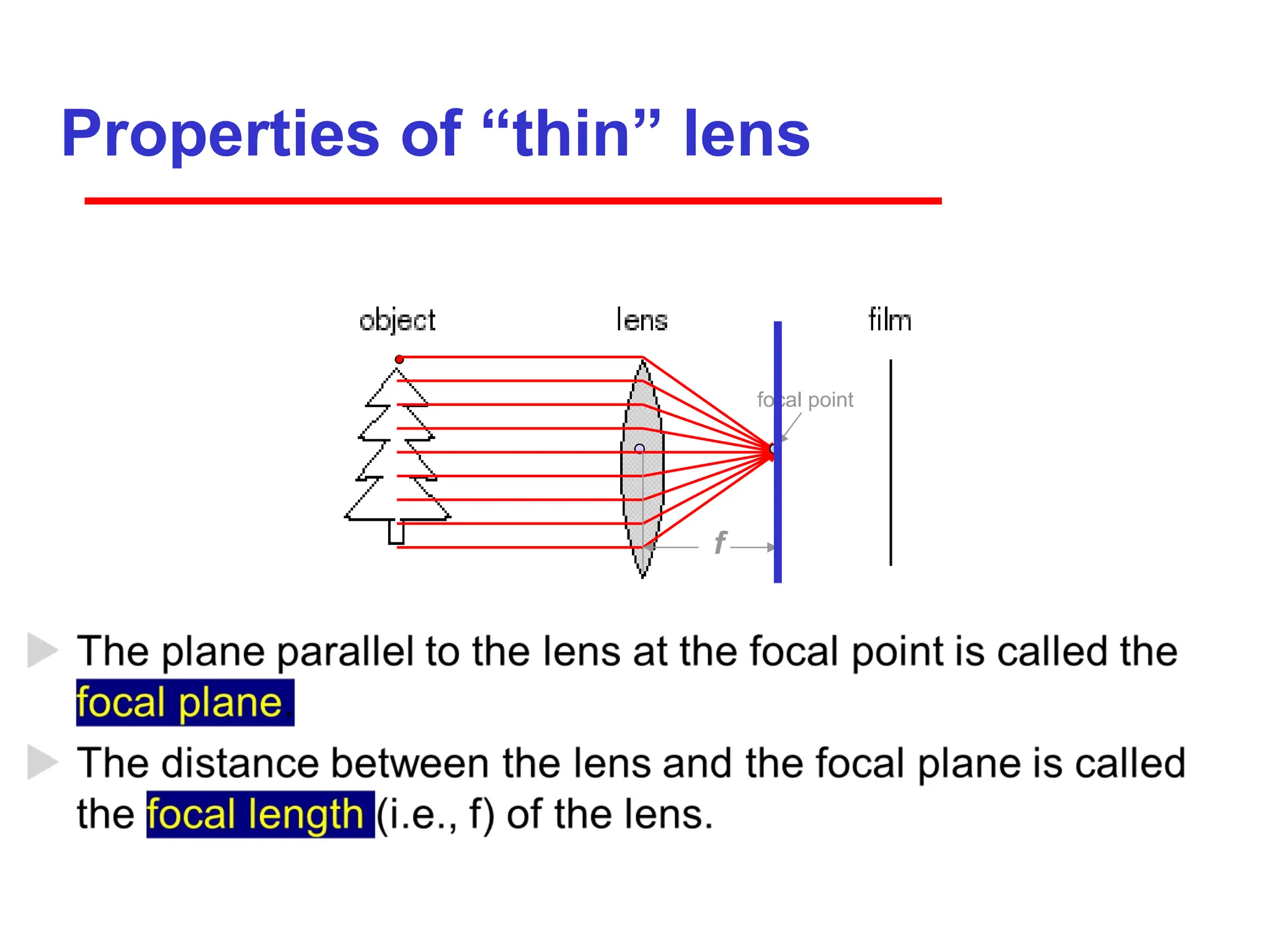
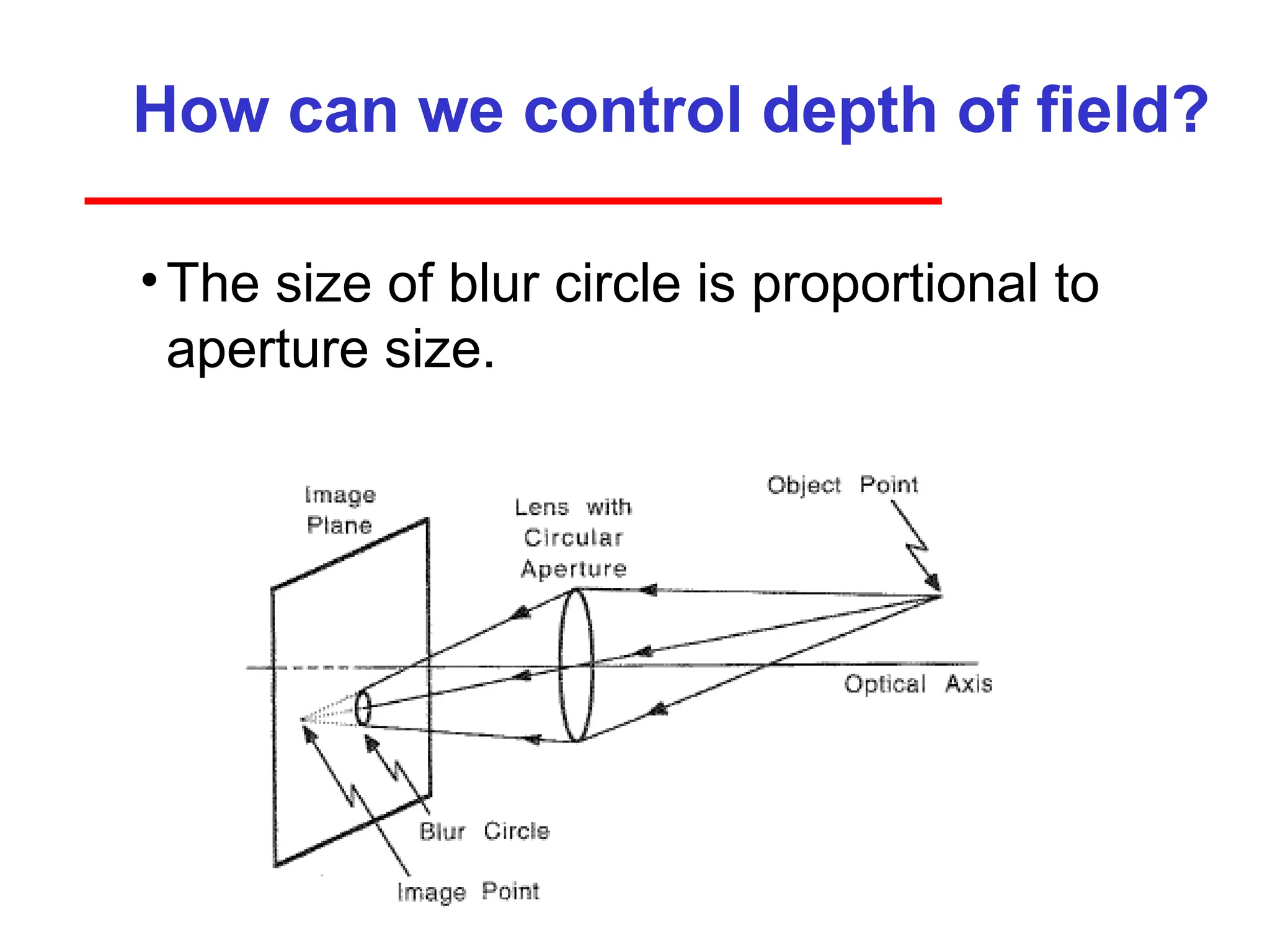
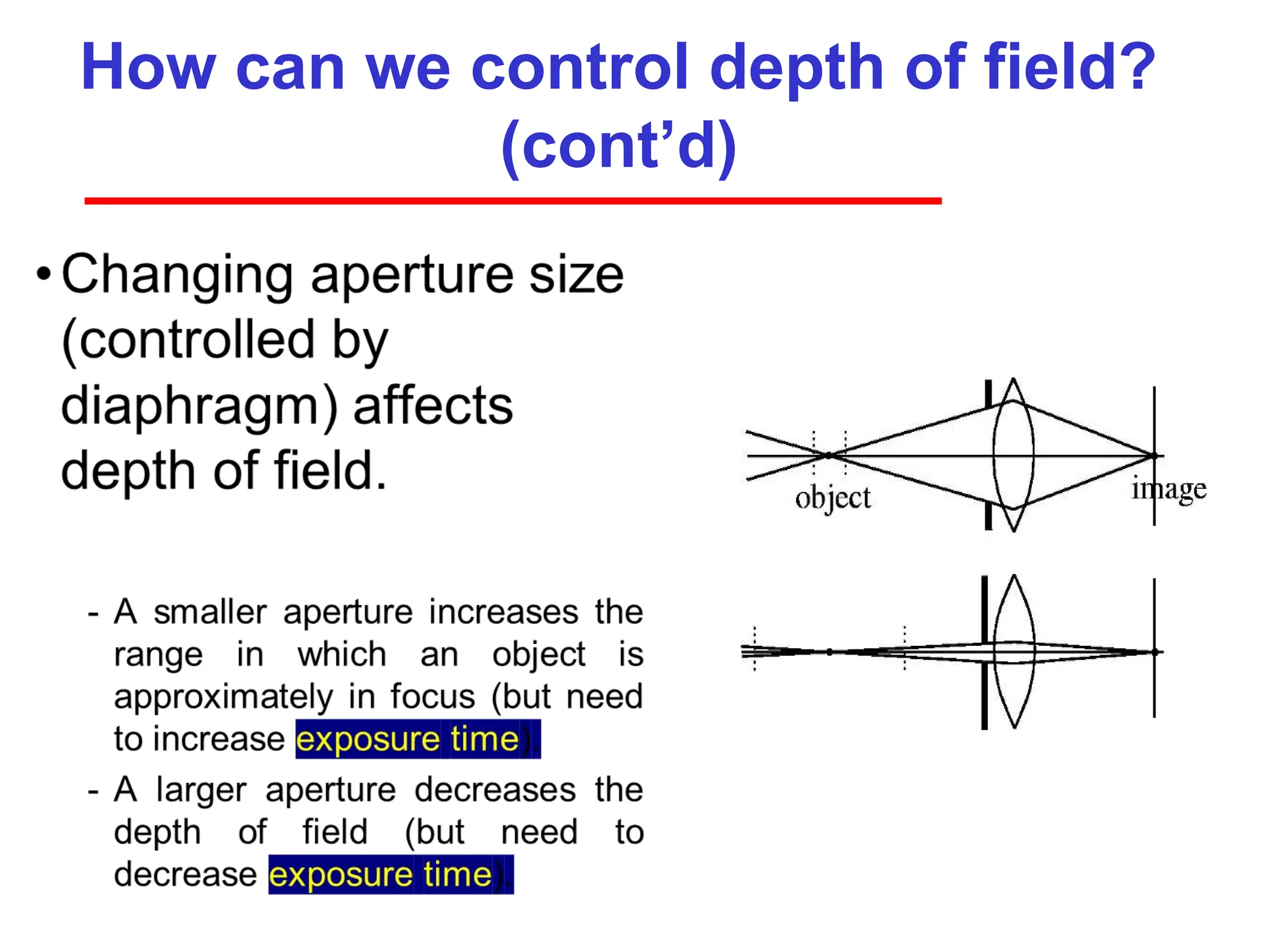
Properties of “thin”lens (i.e., ideal lens)
• Light rays passing through the center are not deviated.
• Light rays passing through a point far away from the center are
deviated more.
focal point
f
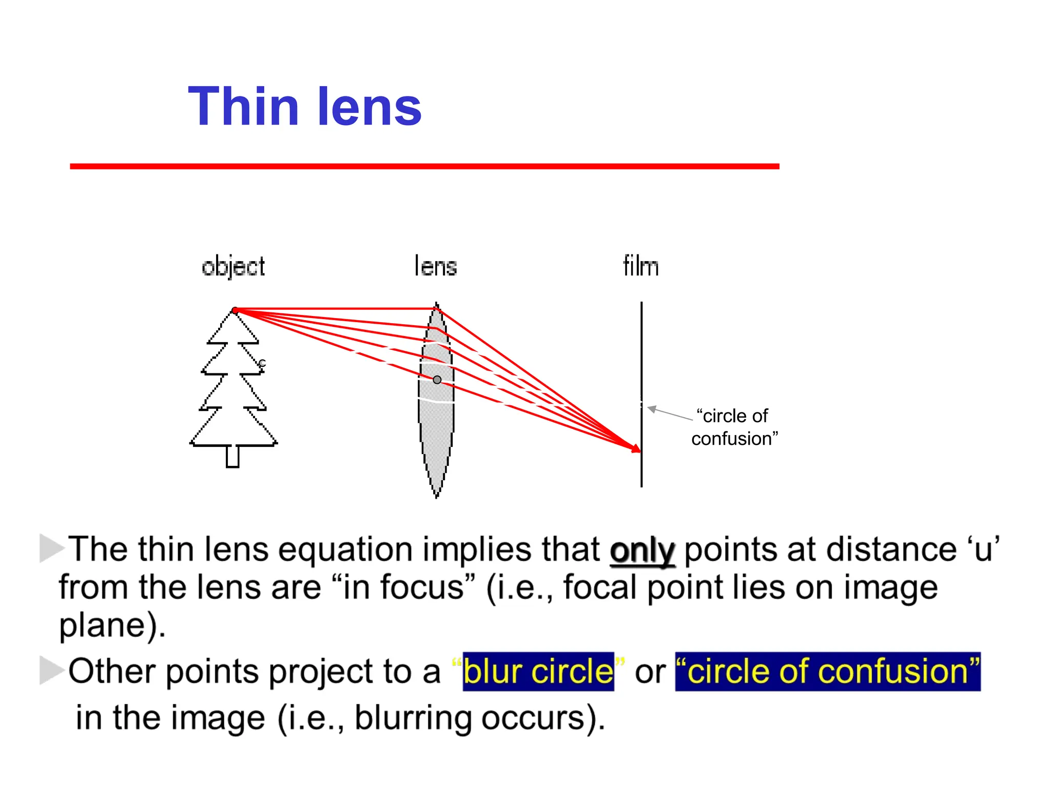
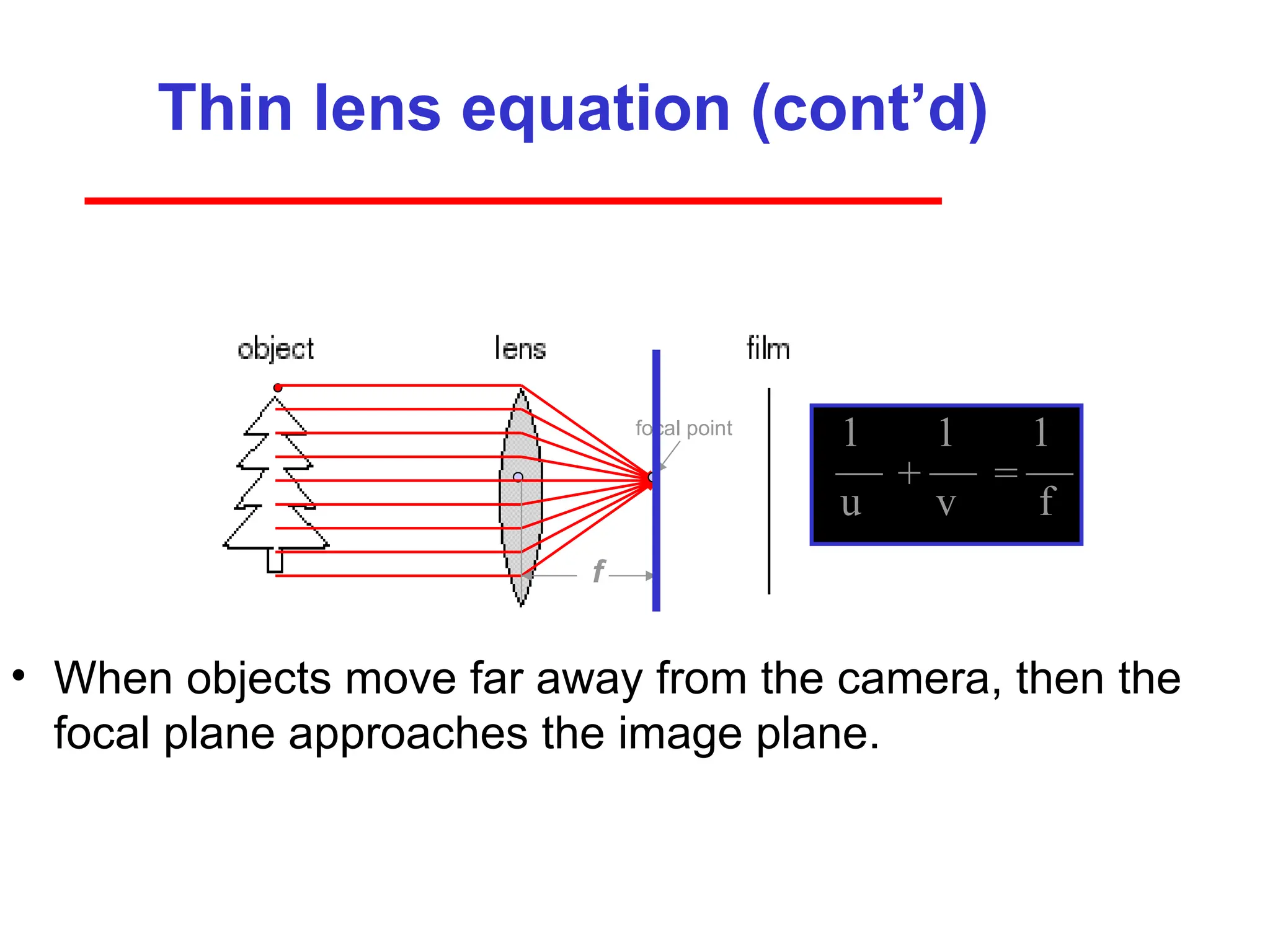
Thin lens equation(cont’d)
• When objects move far away from the camera, then the
focal plane approaches the image plane.
focal point
f
1 1 1
u v f
+ =
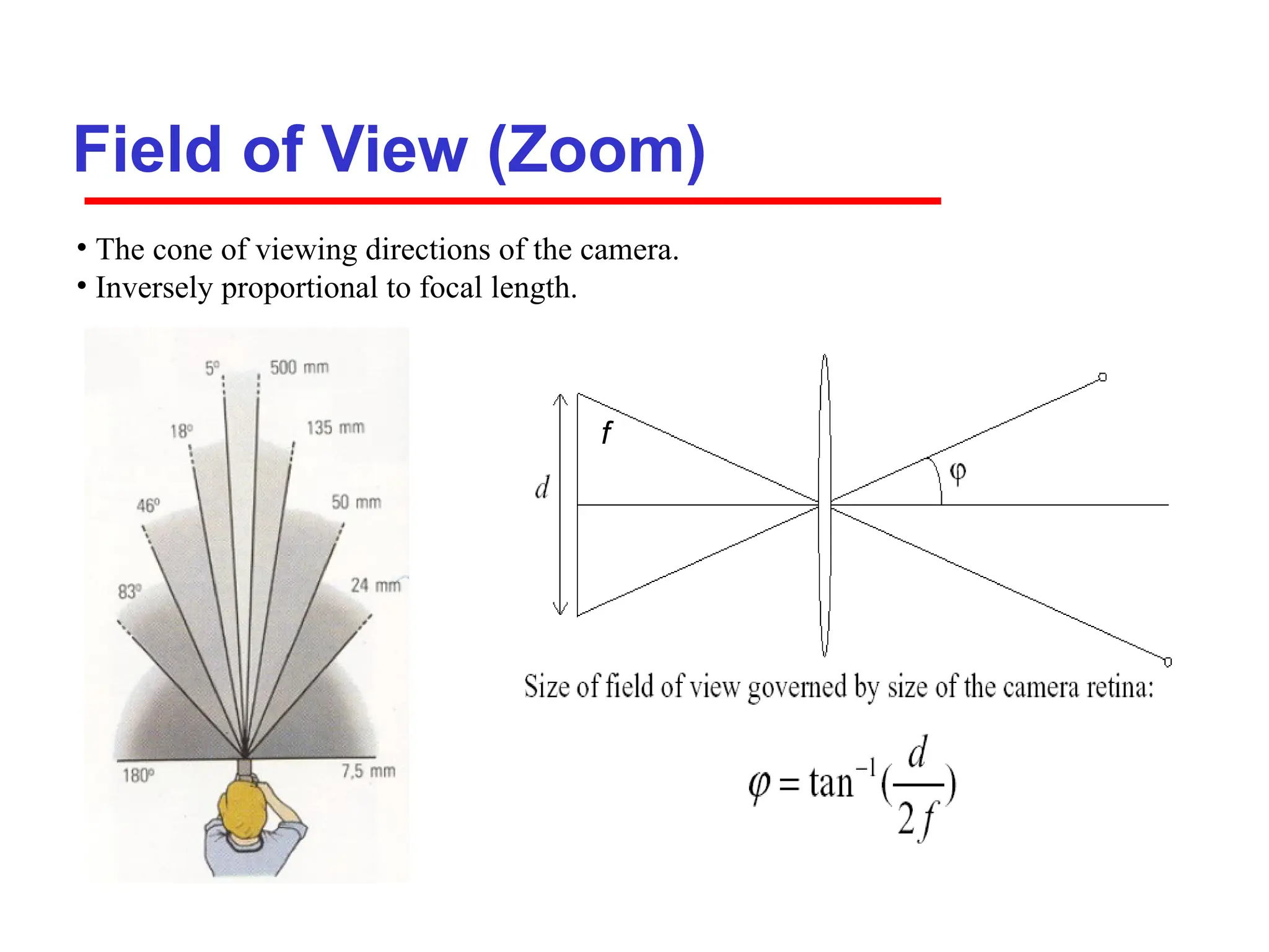
Field of View(Zoom)
f
f
• The cone of viewing directions of the camera.
• Inversely proportional to focal length.
35.
35
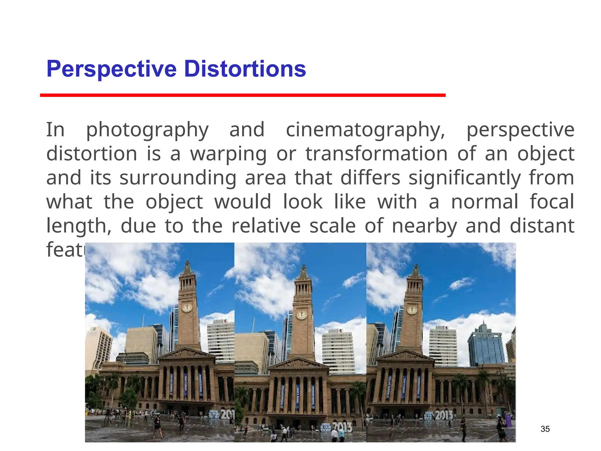
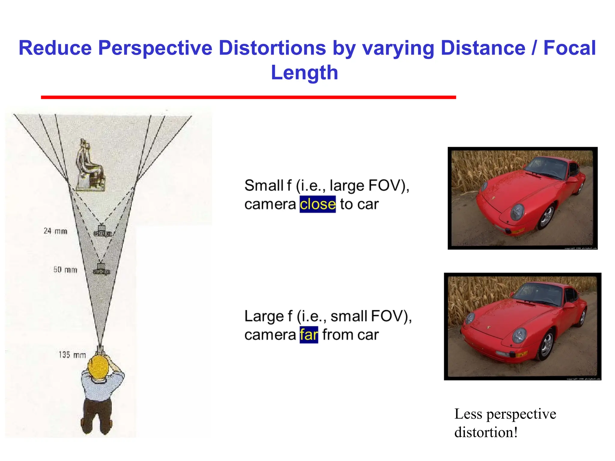
In photography andcinematography, perspective
distortion is a warping or transformation of an object
and its surrounding area that differs significantly from
what the object would look like with a normal focal
length, due to the relative scale of nearby and distant
features.
Perspective Distortions
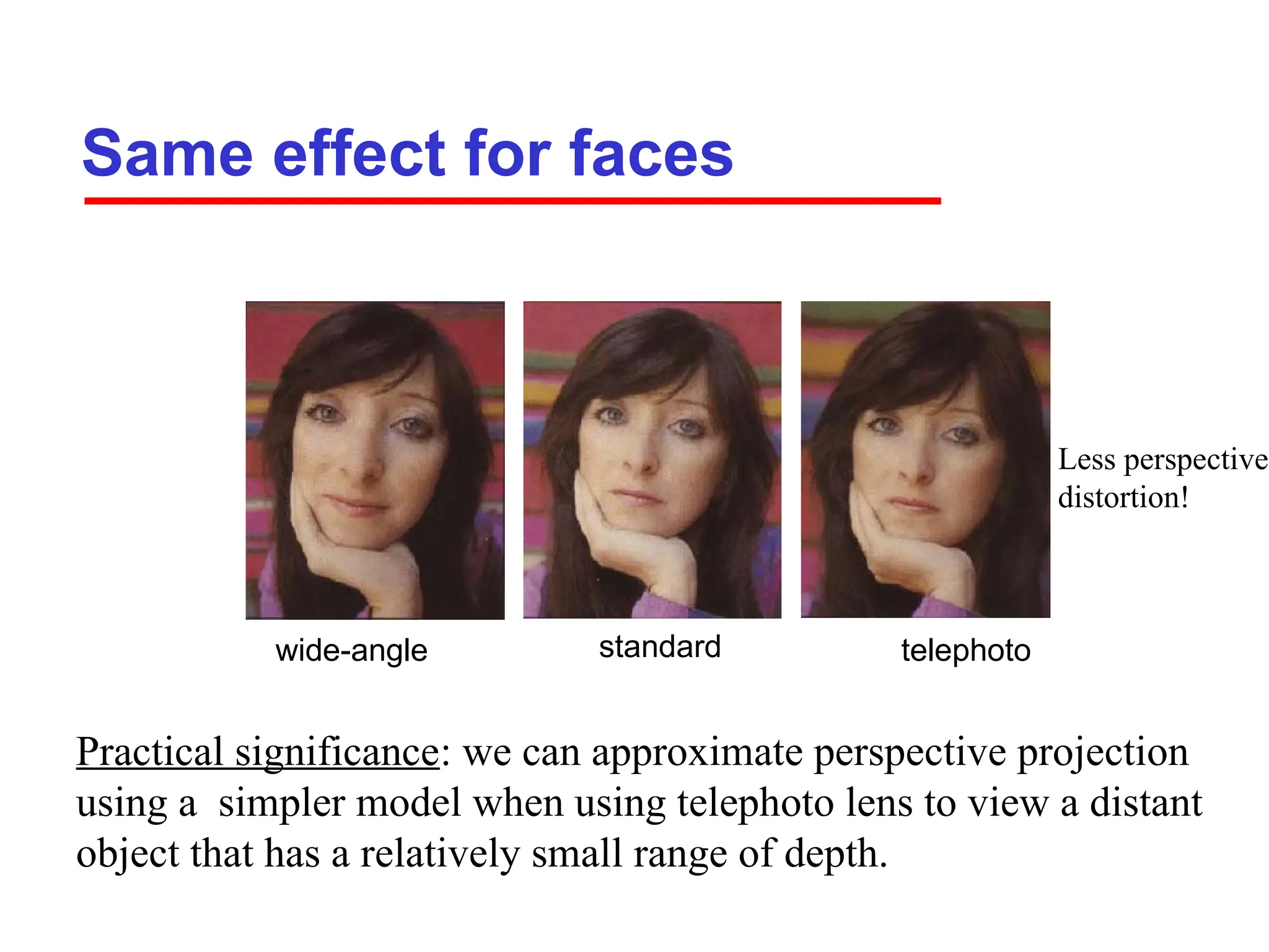
Same effect forfaces
standard
wide-angle telephoto
Practical significance: we can approximate perspective projection
using a simpler model when using telephoto lens to view a distant
object that has a relatively small range of depth.
Less perspective
distortion!
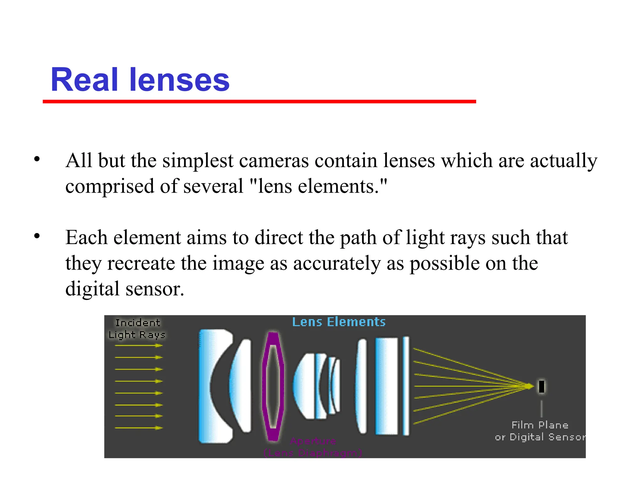
Real lenses
• Allbut the simplest cameras contain lenses which are actually
comprised of several "lens elements."
• Each element aims to direct the path of light rays such that
they recreate the image as accurately as possible on the
digital sensor.
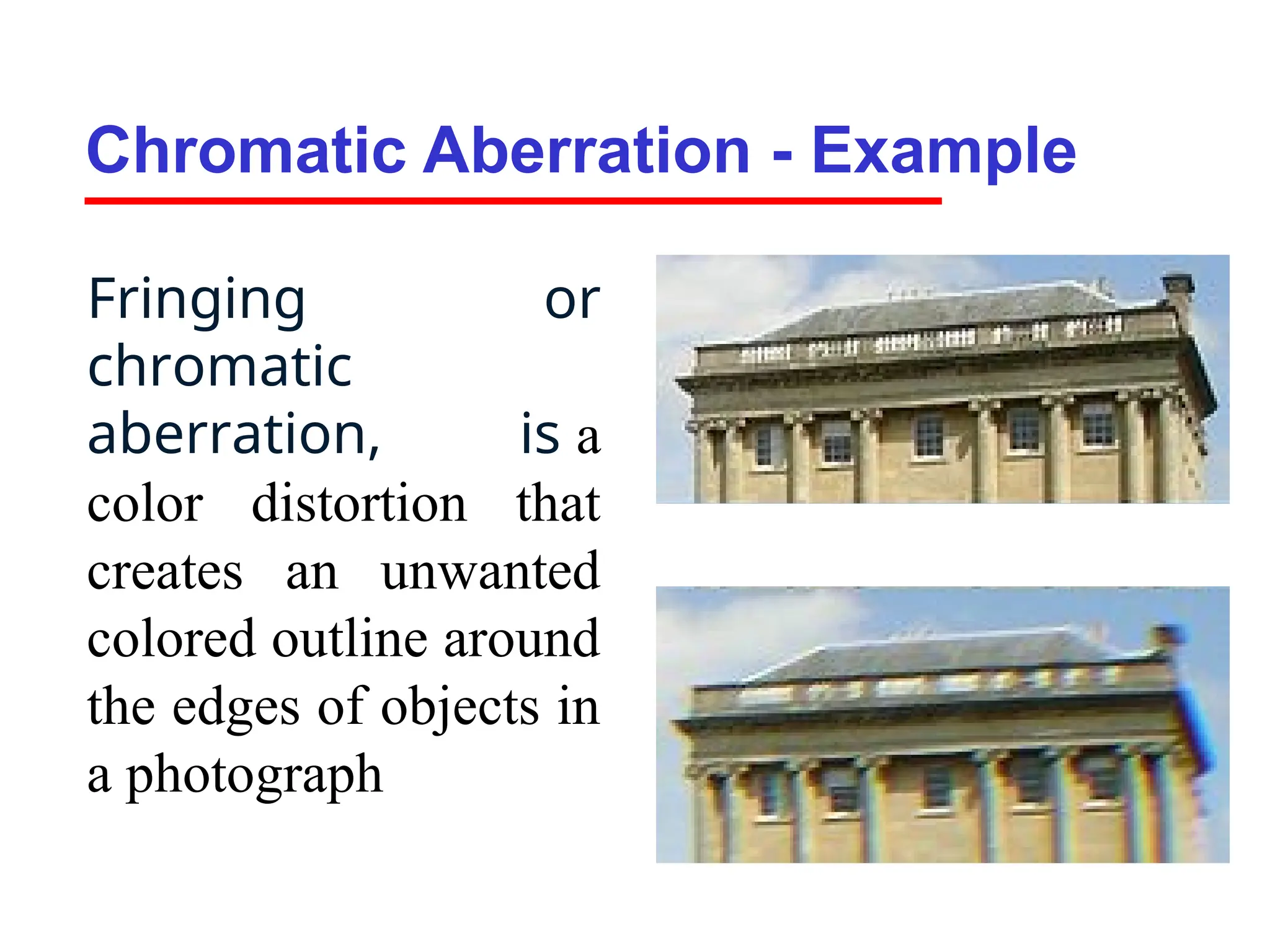
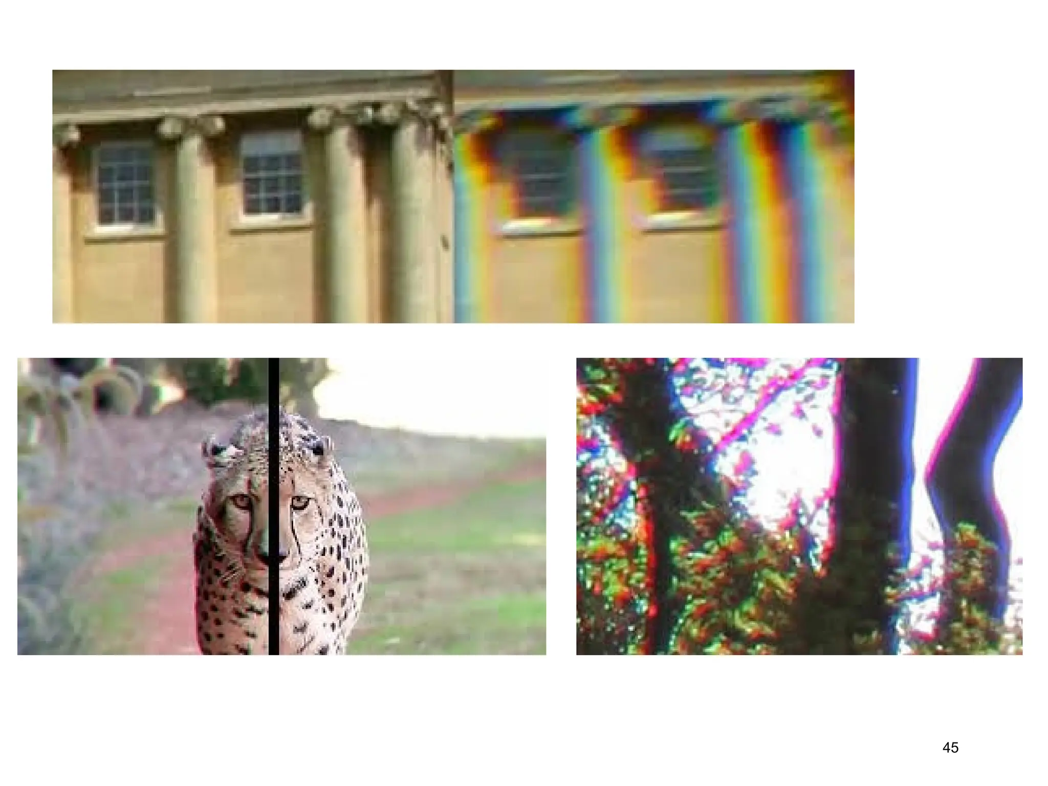
Chromatic Aberration -Example
Fringing or
chromatic
aberration, is a
color distortion that
creates an unwanted
colored outline around
the edges of objects in
a photograph
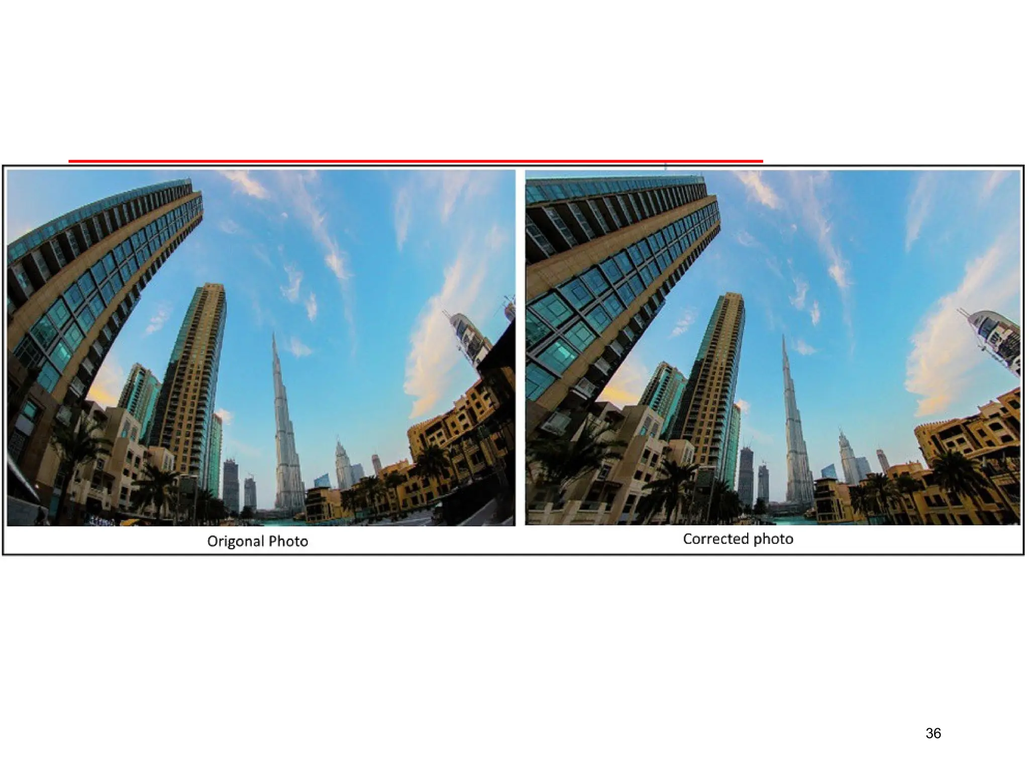
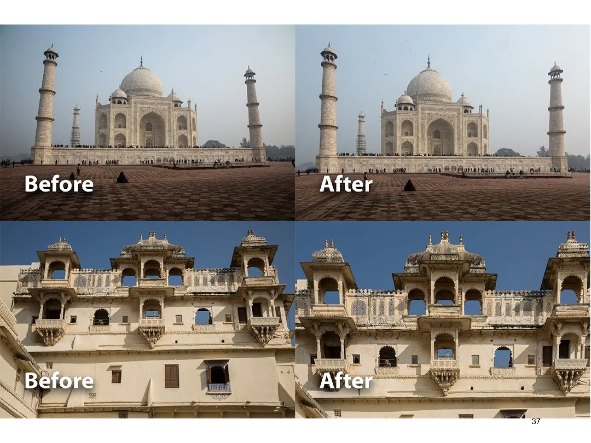
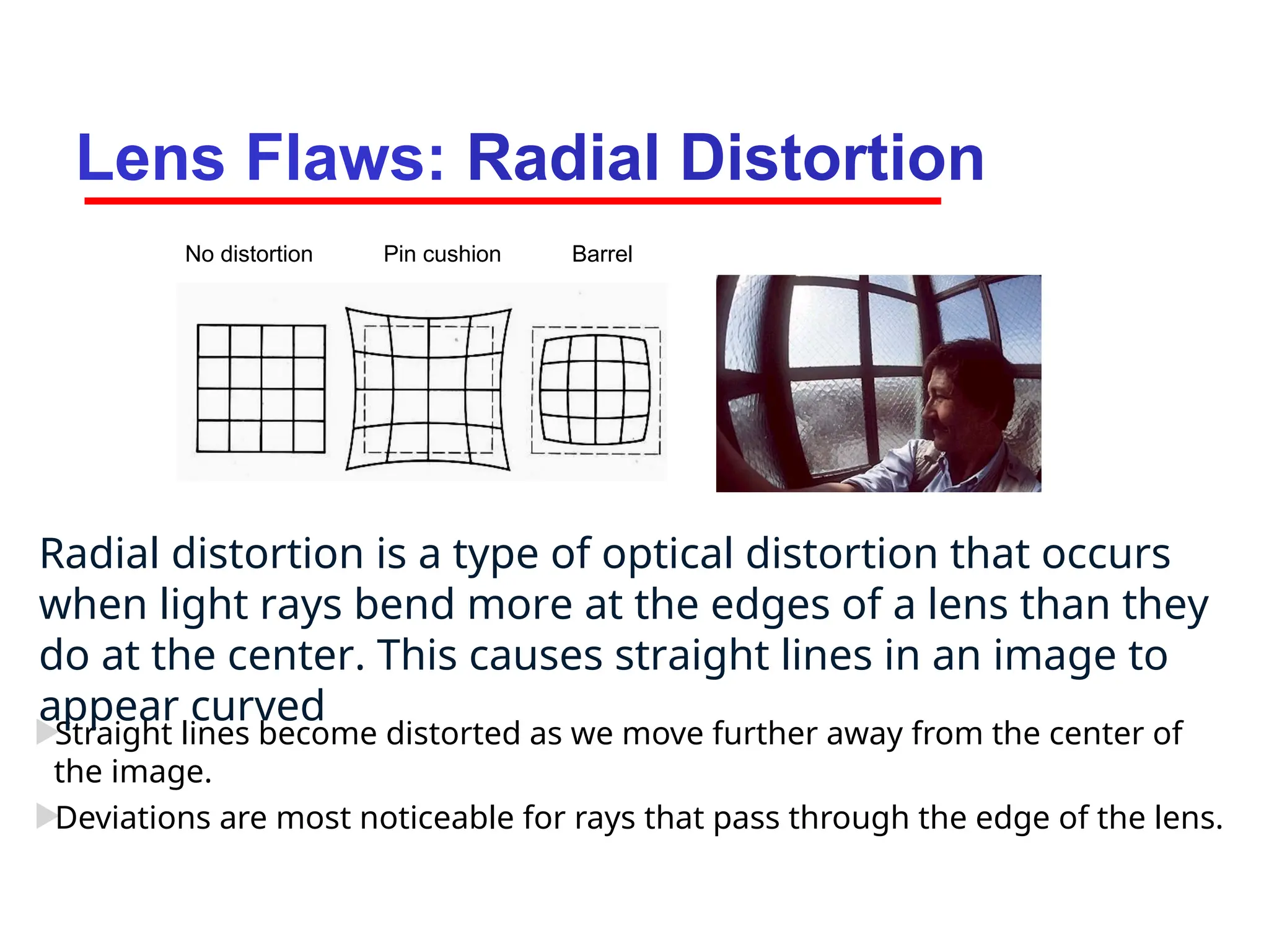
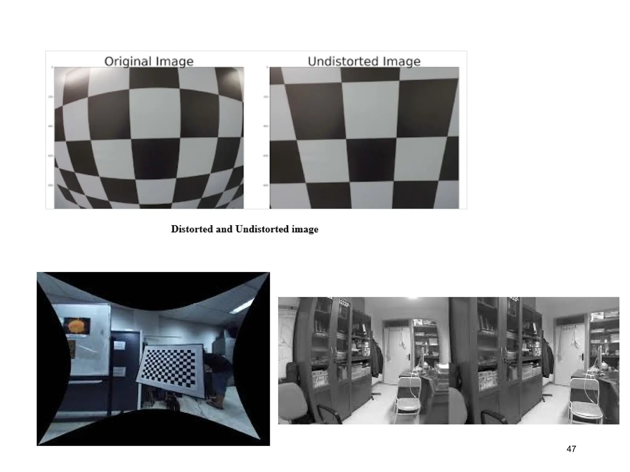
Lens Flaws: RadialDistortion
Straight lines become distorted as we move further away from the center of
the image.
Deviations are most noticeable for rays that pass through the edge of the lens.
No distortion Pin cushion Barrel
Radial distortion is a type of optical distortion that occurs
when light rays bend more at the edges of a lens than they
do at the center. This causes straight lines in an image to
appear curved
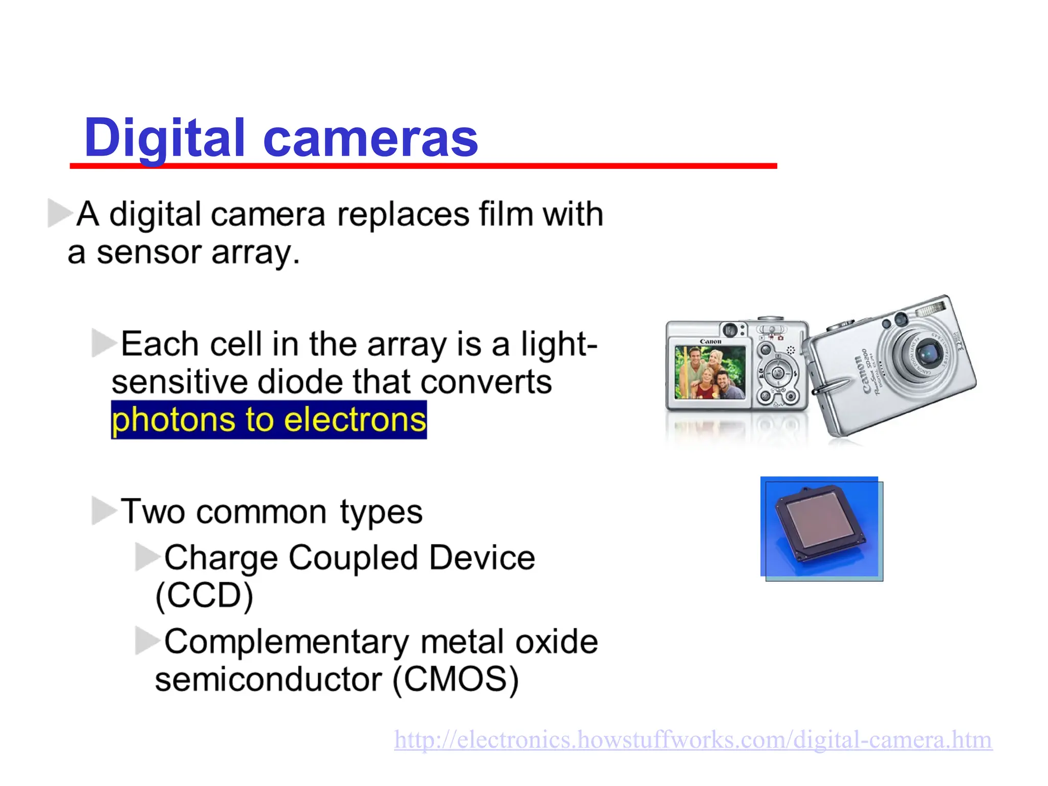
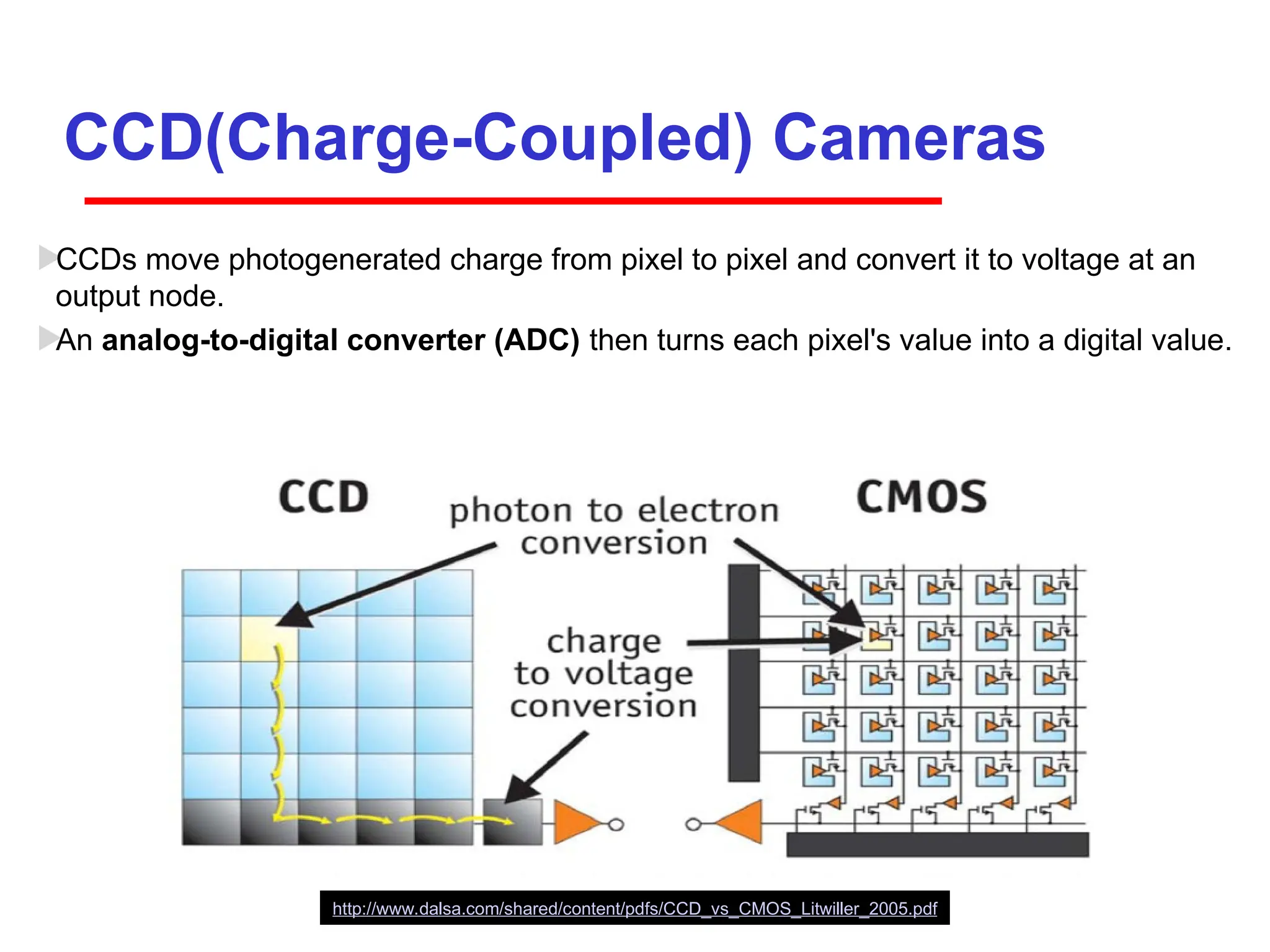
CCD(Charge-Coupled) Cameras
CCDs movephotogenerated charge from pixel to pixel and convert it to voltage at an
output node.
An analog-to-digital converter (ADC) then turns each pixel's value into a digital value.
http://www.dalsa.com/shared/content/pdfs/CCD_vs_CMOS_Litwiller_2005.pdf
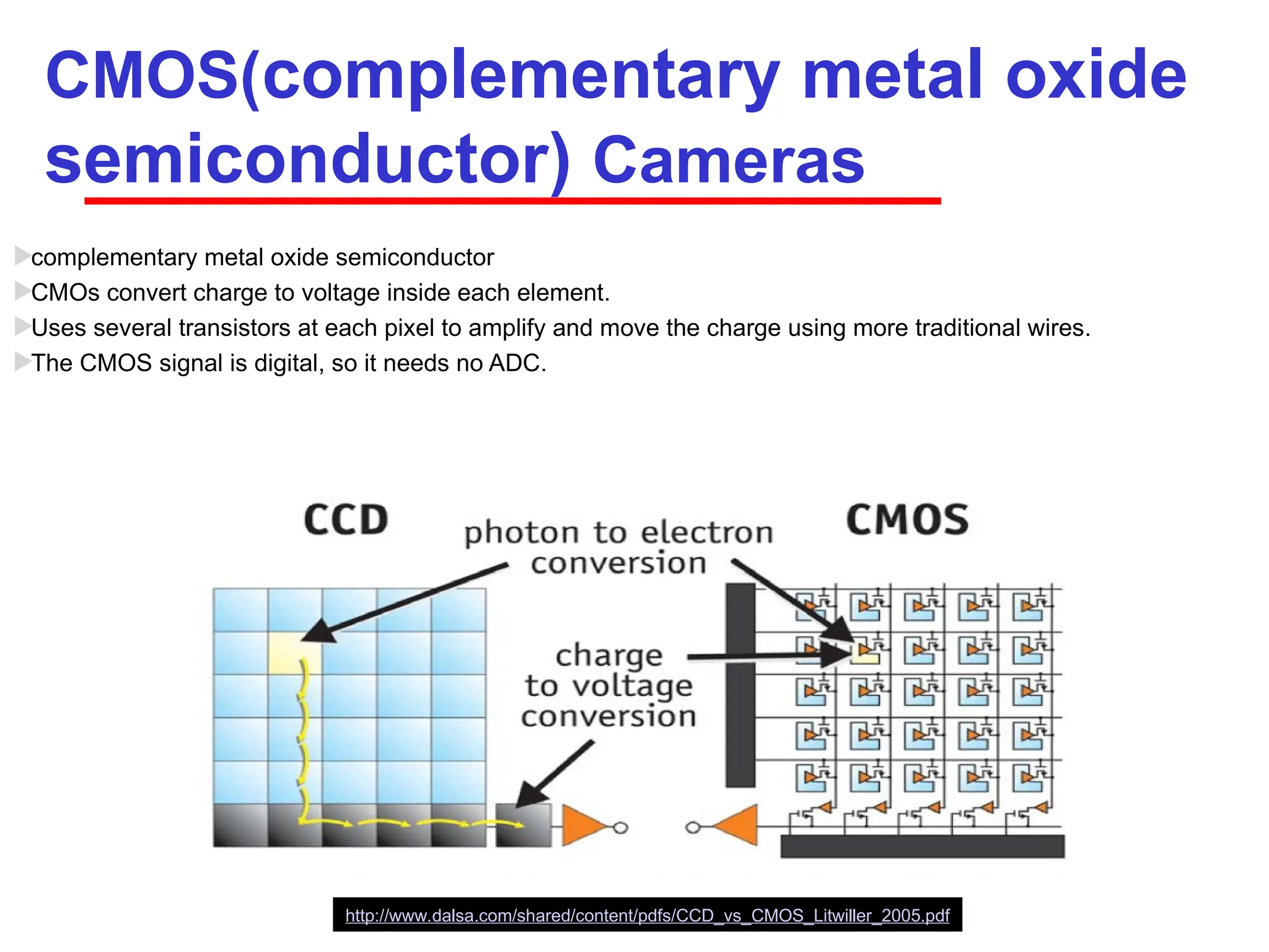
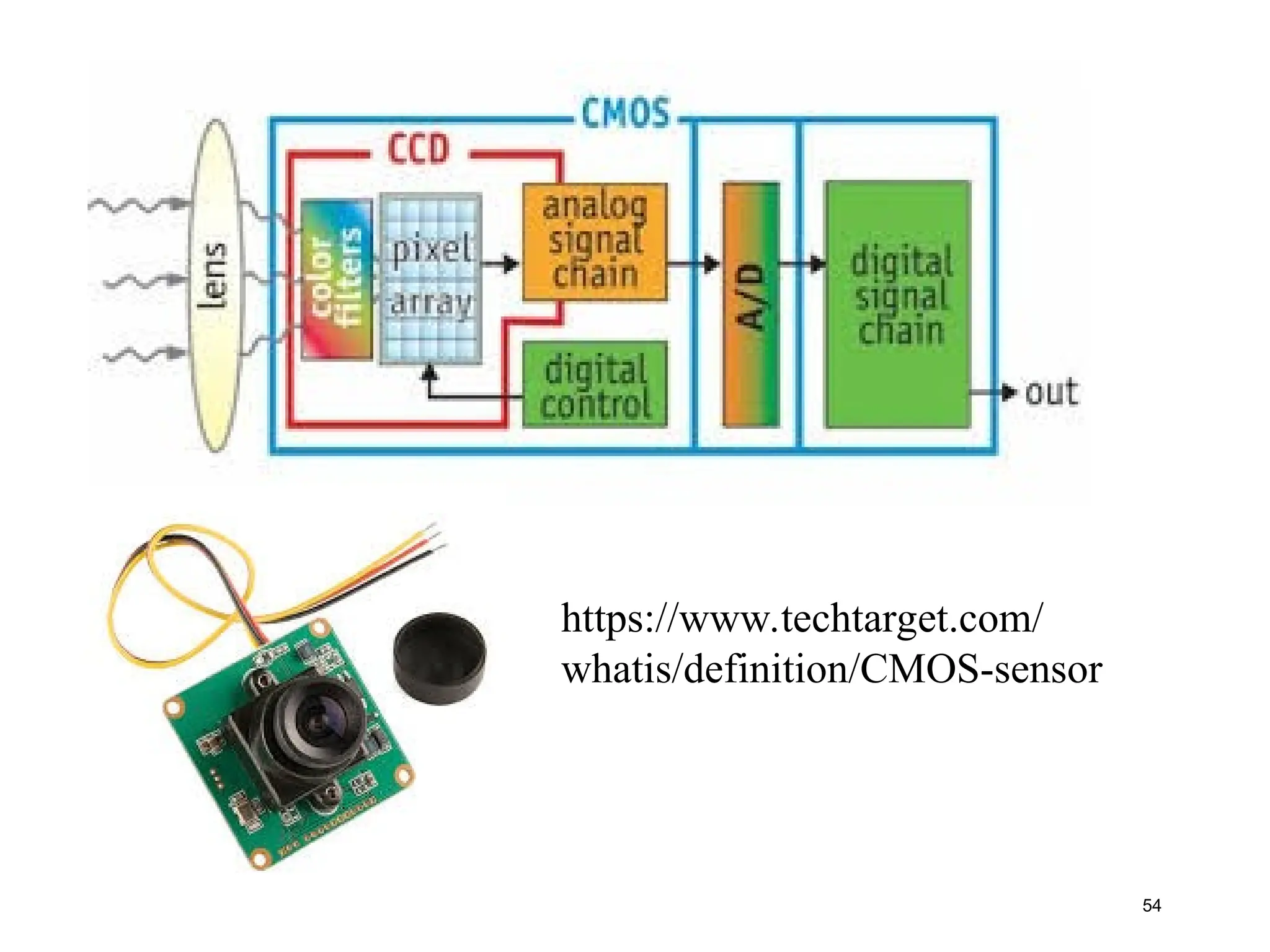
CMOS(complementary metal oxide
semiconductor)Cameras
complementary metal oxide semiconductor
CMOs convert charge to voltage inside each element.
Uses several transistors at each pixel to amplify and move the charge using more traditional wires.
The CMOS signal is digital, so it needs no ADC.
http://www.dalsa.com/shared/content/pdfs/CCD_vs_CMOS_Litwiller_2005.pdf
55
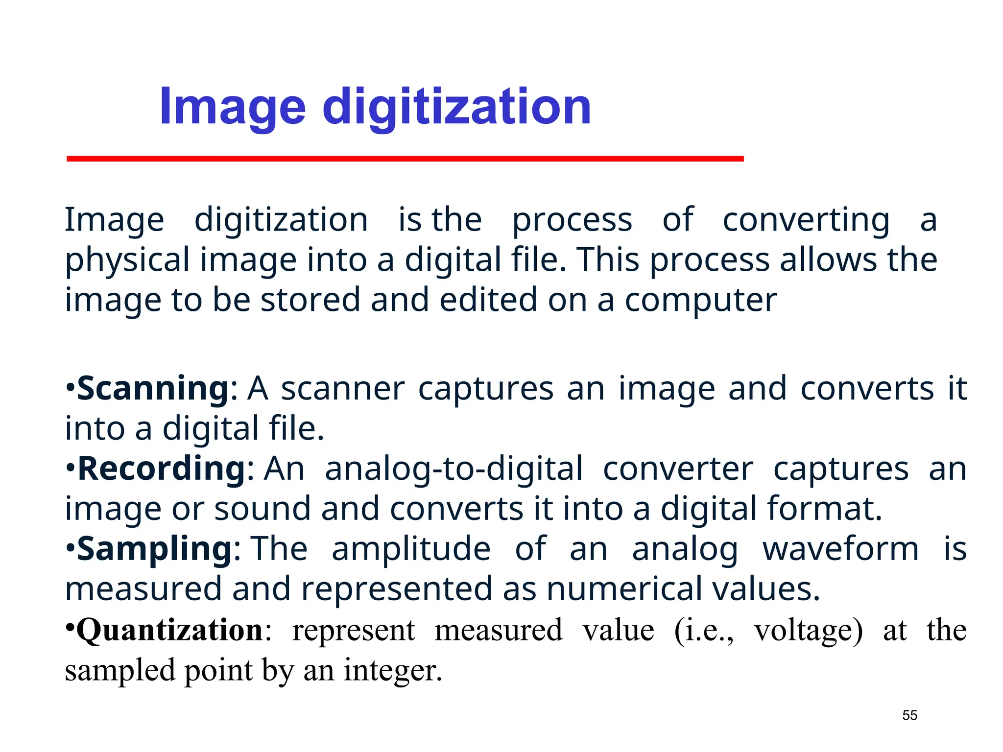
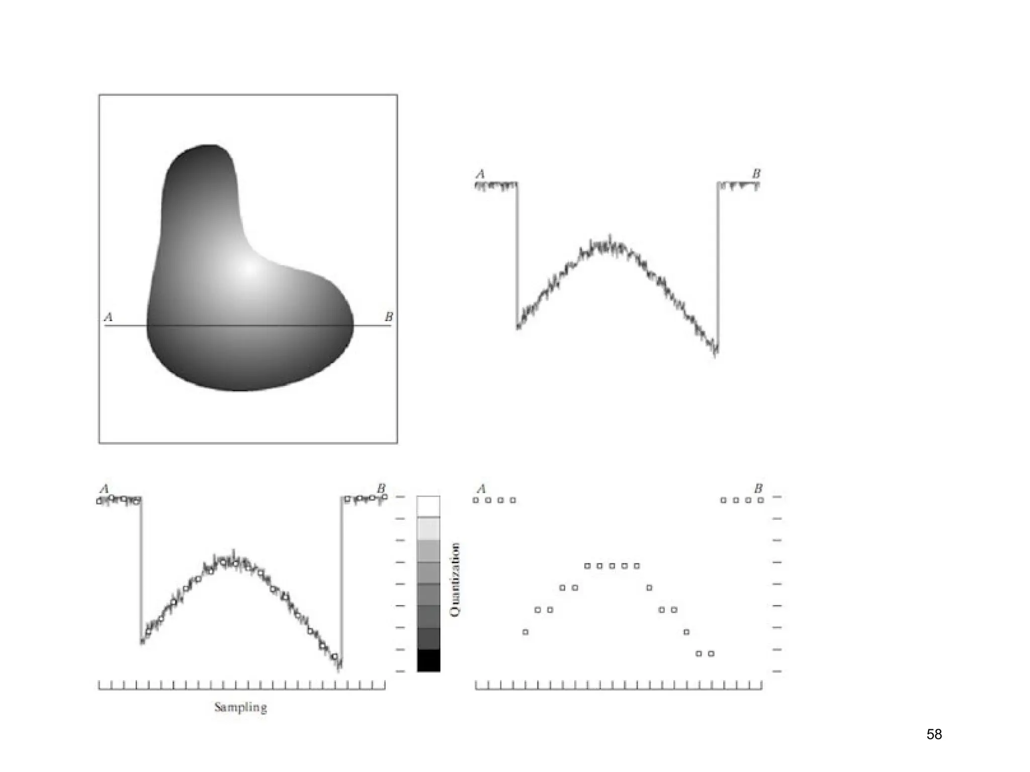
Image digitization
Image digitizationis the process of converting a
physical image into a digital file. This process allows the
image to be stored and edited on a computer
•Scanning: A scanner captures an image and converts it
into a digital file.
•Recording: An analog-to-digital converter captures an
image or sound and converts it into a digital format.
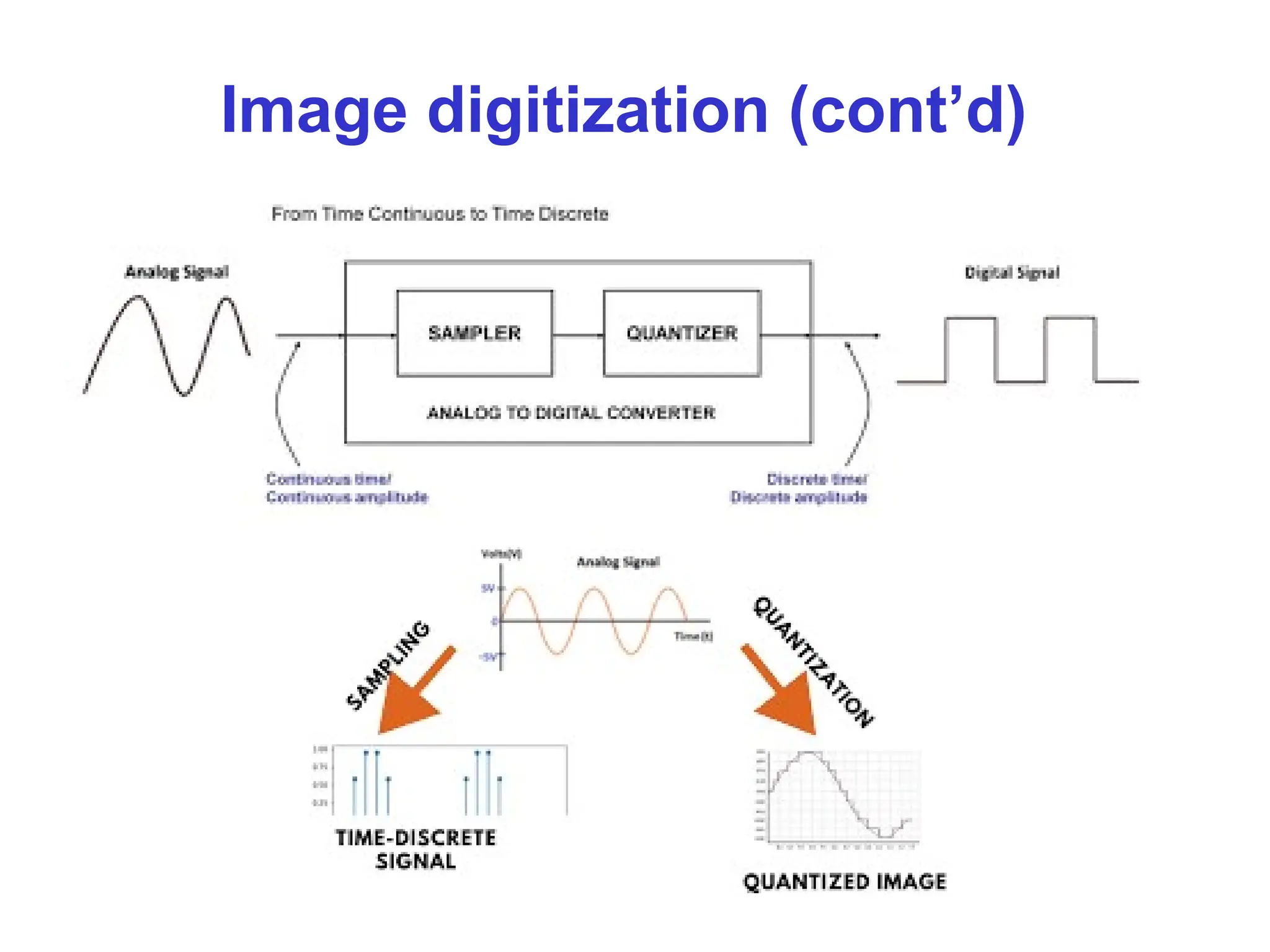
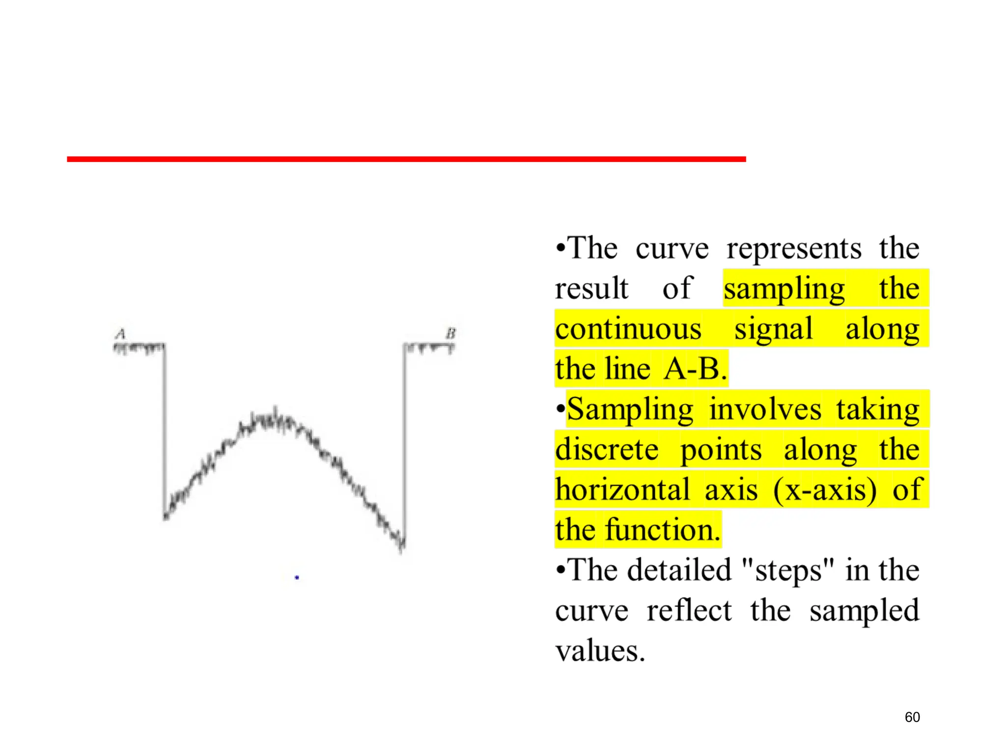
•Sampling: The amplitude of an analog waveform is
measured and represented as numerical values.
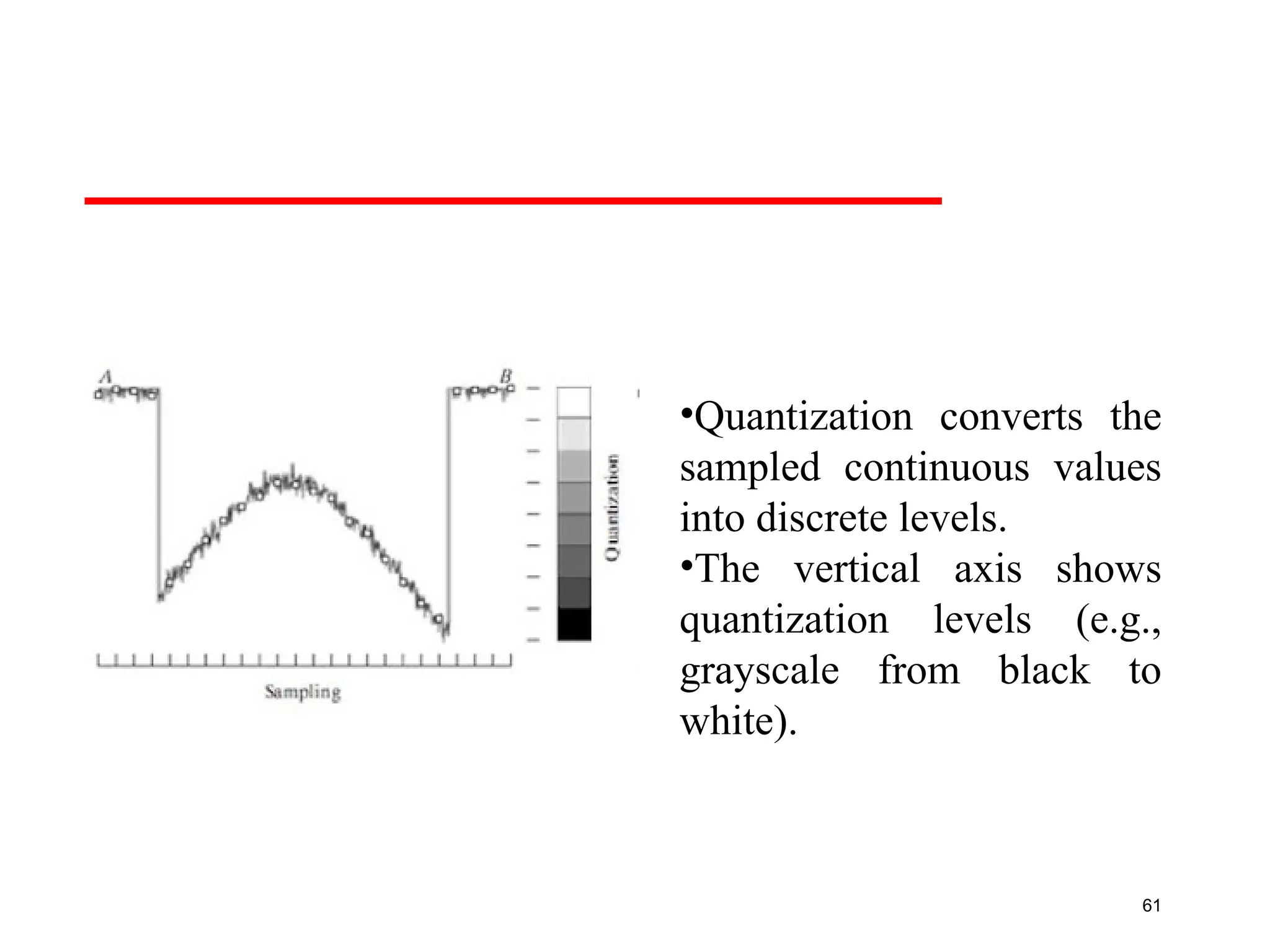
•Quantization: represent measured value (i.e., voltage) at the
sampled point by an integer.
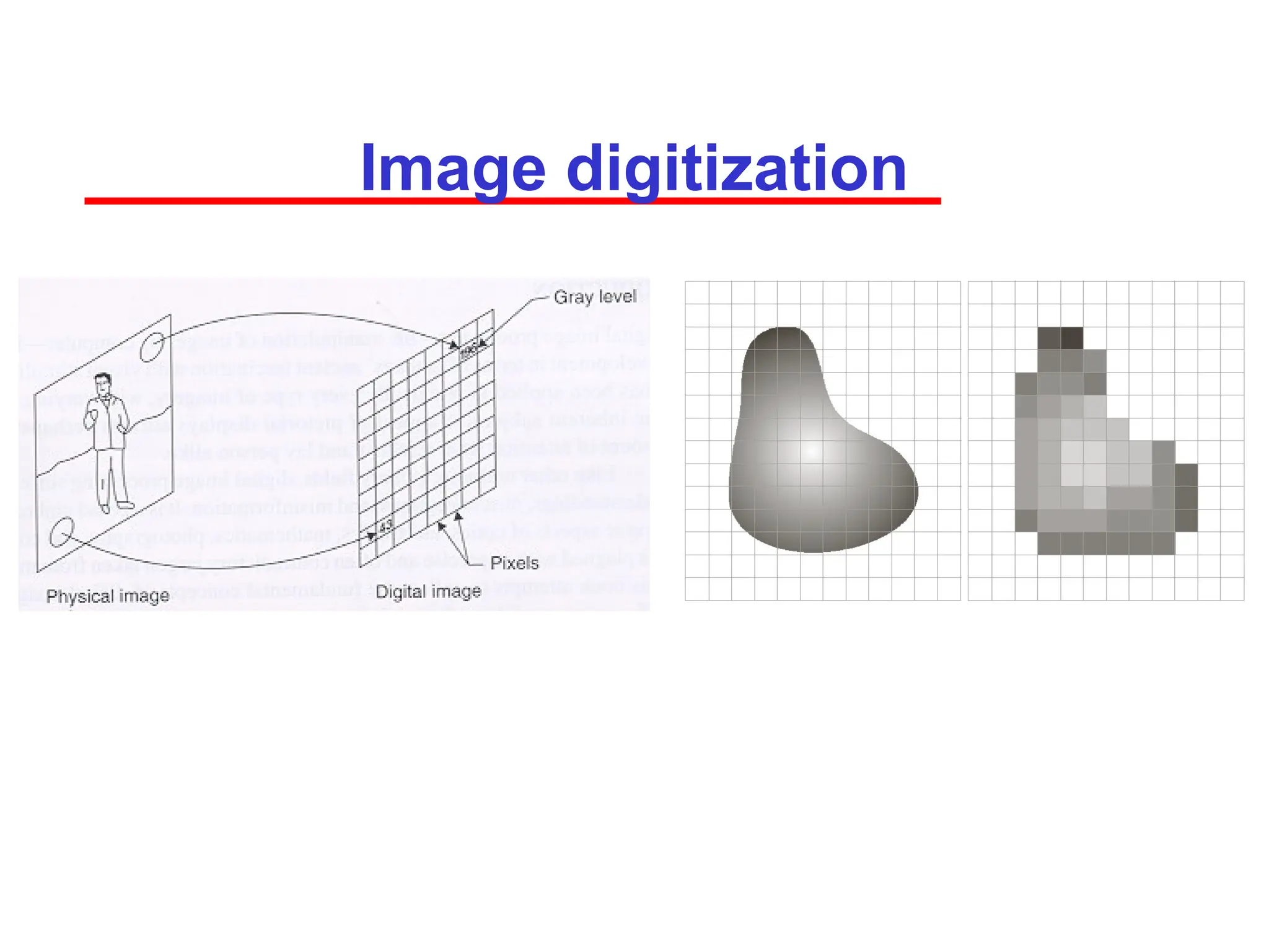
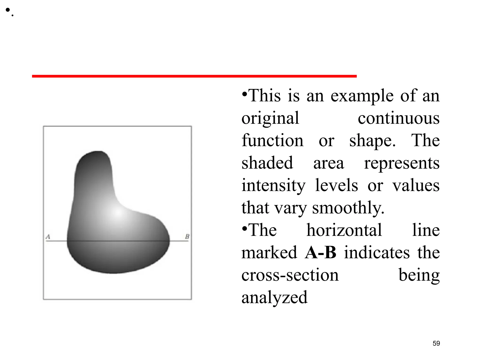
•This is anexample of an
original continuous
function or shape. The
shaded area represents
intensity levels or values
that vary smoothly.
•The horizontal line
marked A-B indicates the
cross-section being
analyzed
59
•.
61
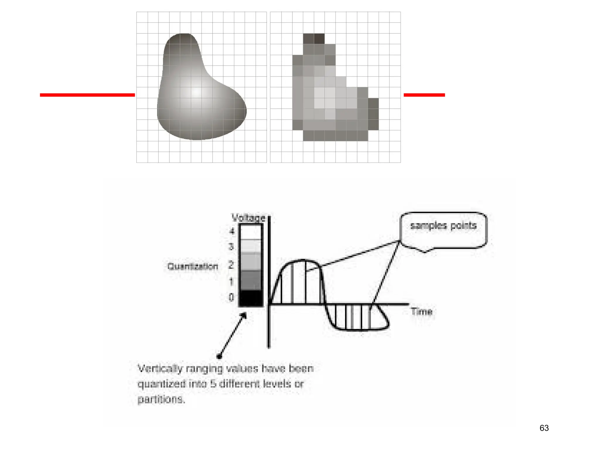
•Quantization converts the
sampledcontinuous values
into discrete levels.
•The vertical axis shows
quantization levels (e.g.,
grayscale from black to
white).
62.
62
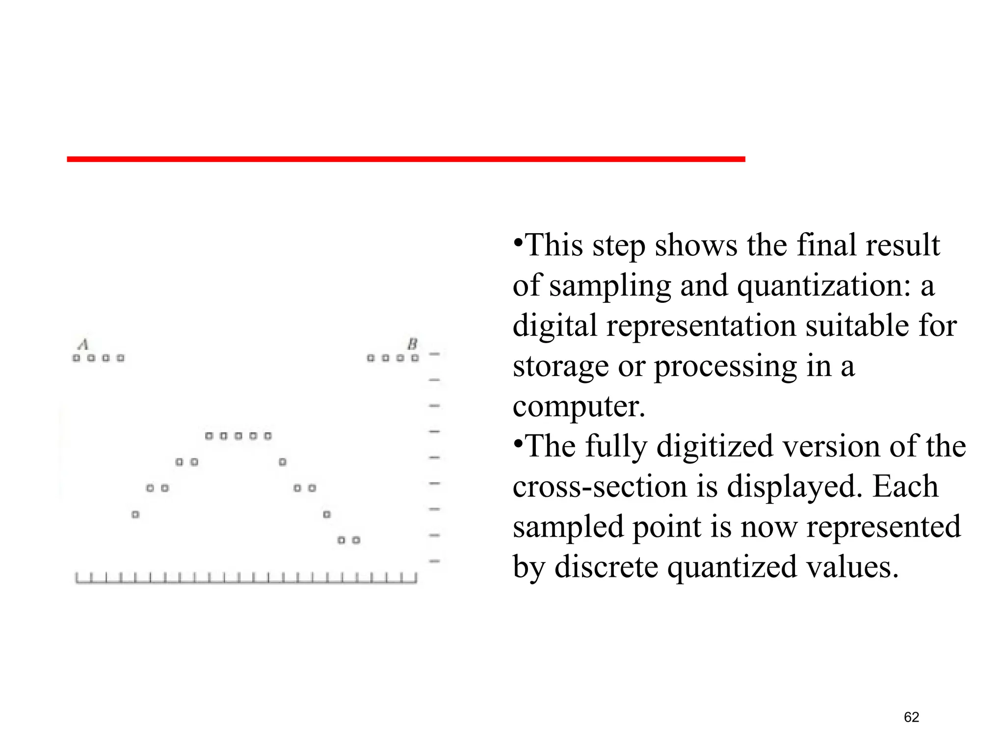
•This step showsthe final result
of sampling and quantization: a
digital representation suitable for
storage or processing in a
computer.
•The fully digitized version of the
cross-section is displayed. Each
sampled point is now represented
by discrete quantized values.
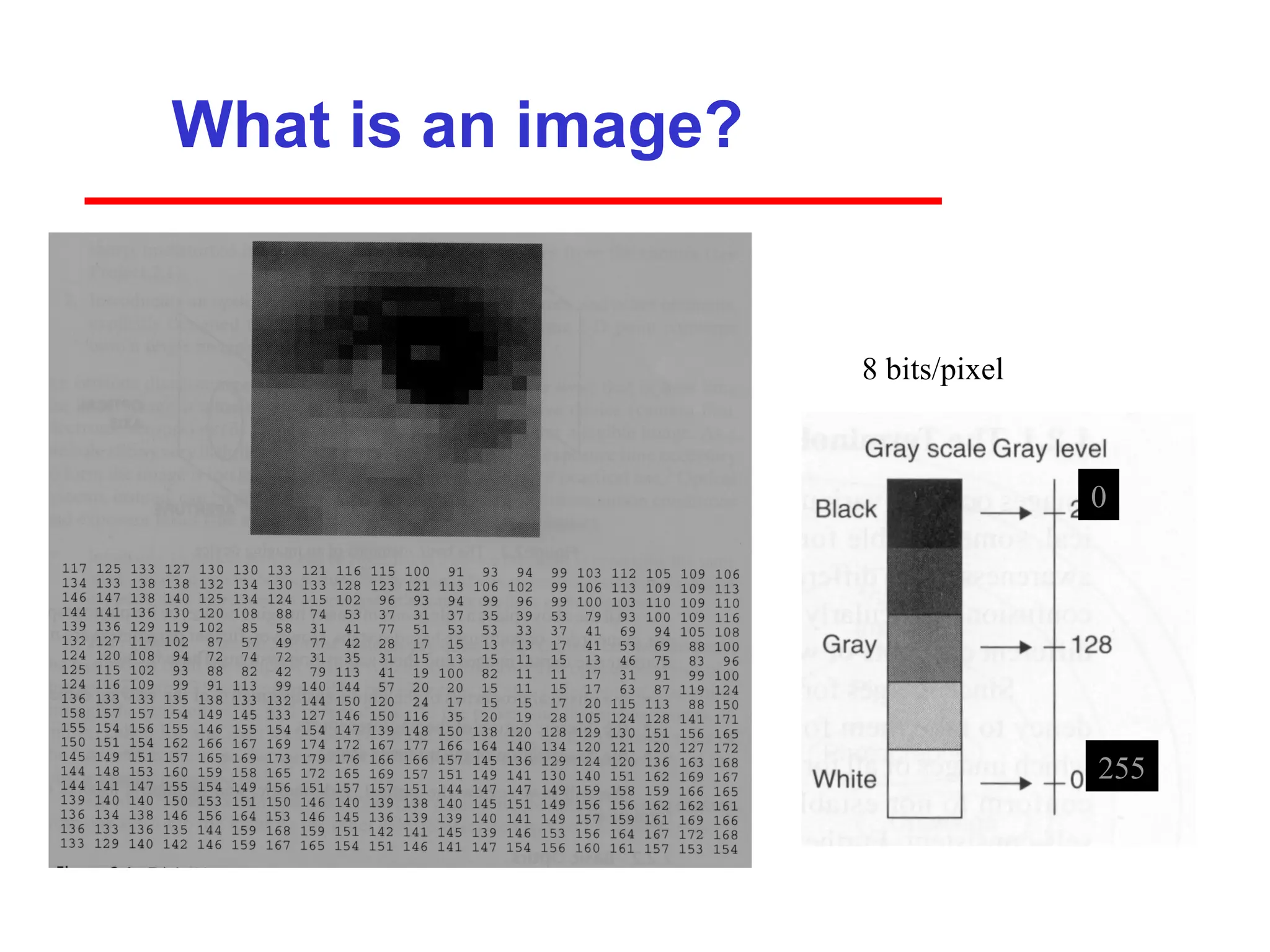
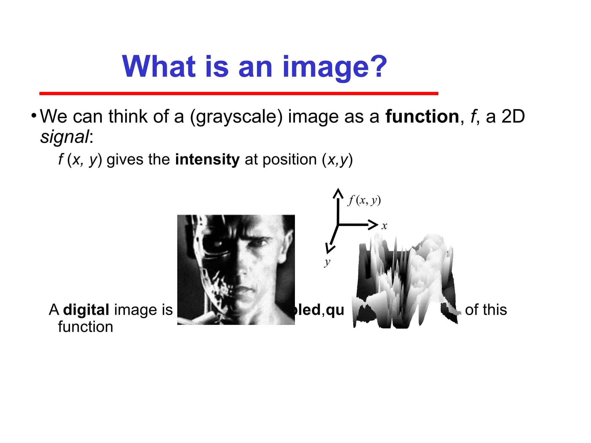
What is animage?
•We can think of a (grayscale) image as a function, f, a 2D
signal:
f (x, y) gives the intensity at position (x,y)
A digital image is a discrete (sampled,quantized) version of this
function
x
y
f (x, y)
66.
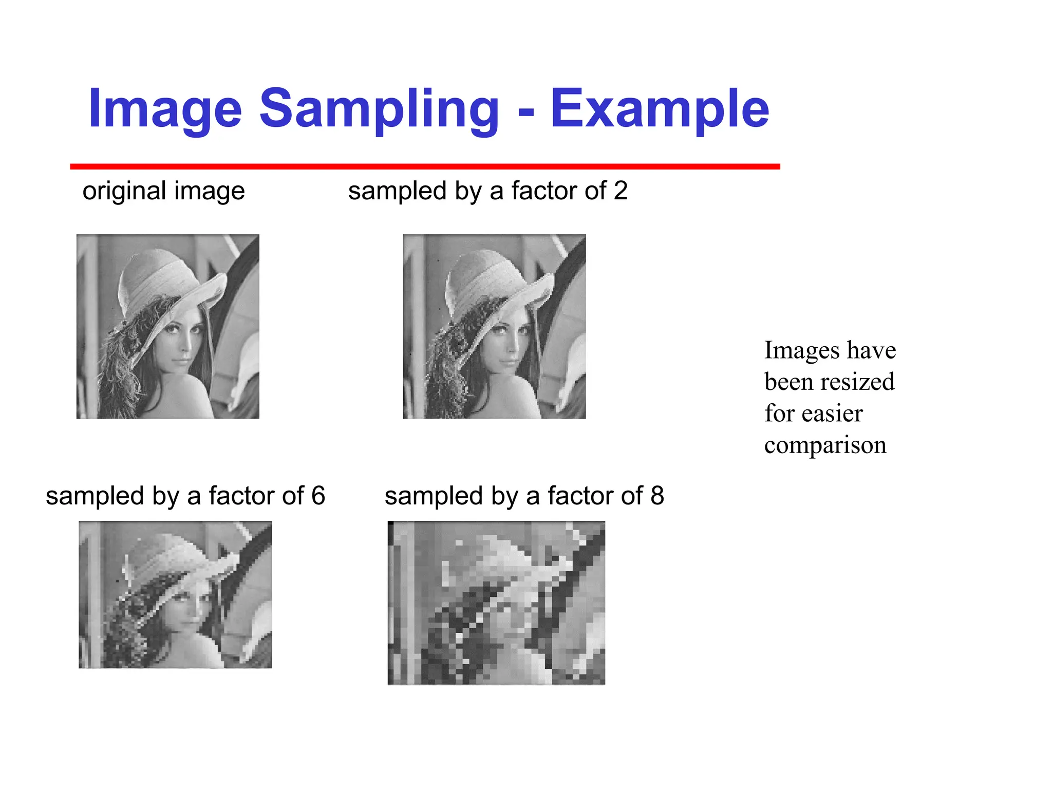
Image Sampling -Example
original image sampled by a factor of 2
sampled by a factor of 6 sampled by a factor of 8
Images have
been resized
for easier
comparison
67.
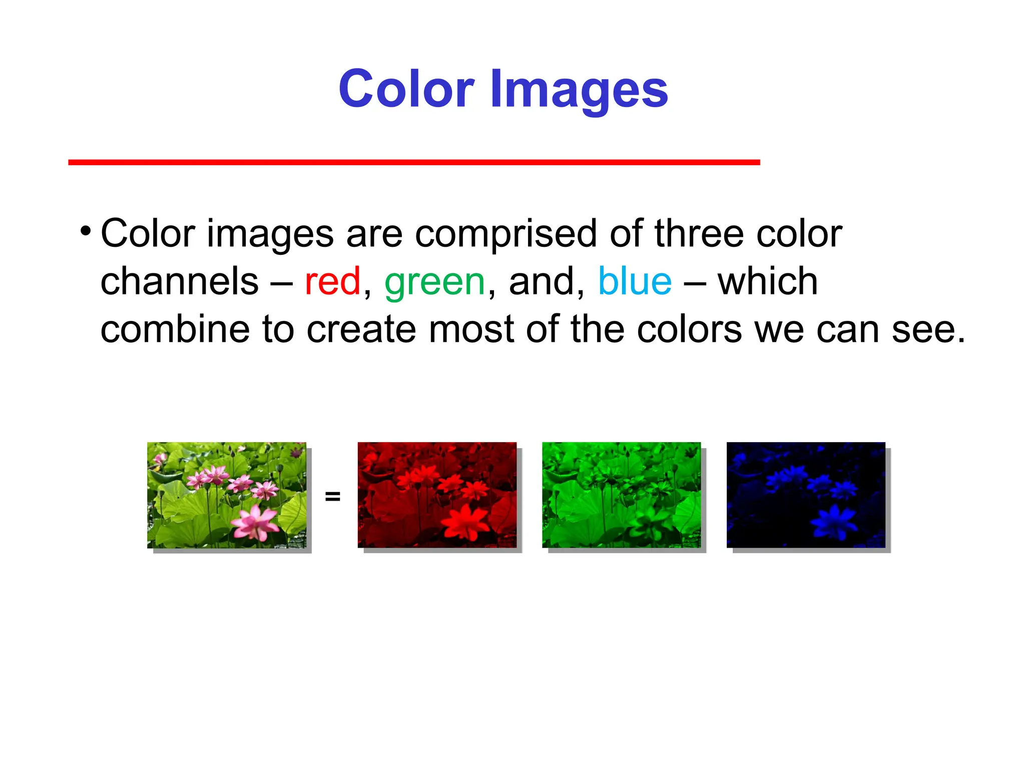
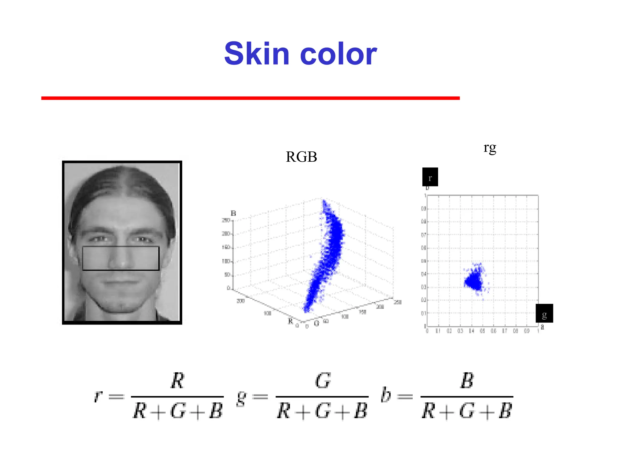
Color Images
• Colorimages are comprised of three color
channels – red, green, and, blue – which
combine to create most of the colors we can see.
=
68.
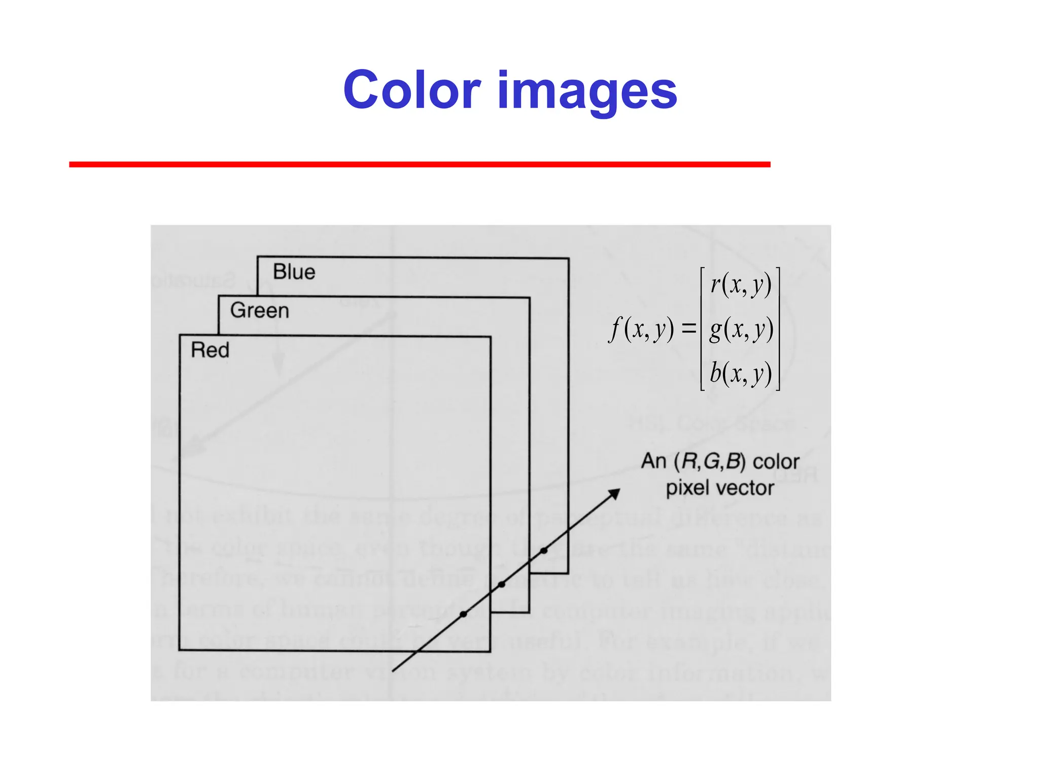
Color images
( ,)
( , ) ( , )
( , )
r x y
f x y g x y
b x y
69.
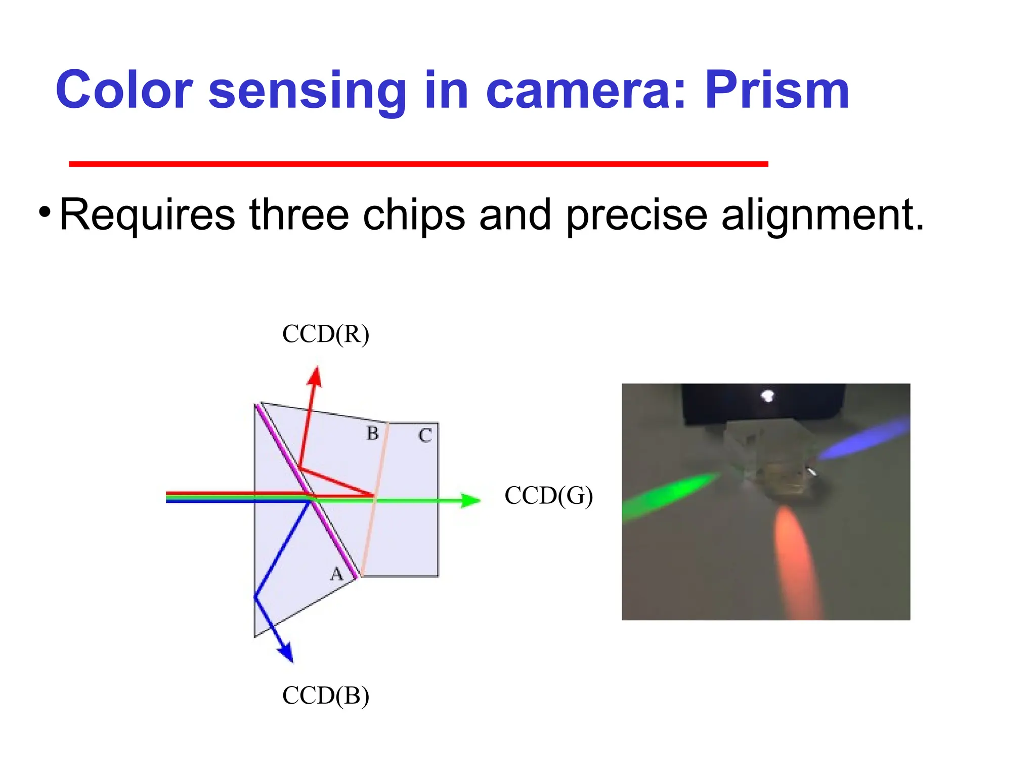
Color sensing incamera: Prism
•Requires three chips and precise alignment.
CCD(B)
CCD(G)
CCD(R)
70.
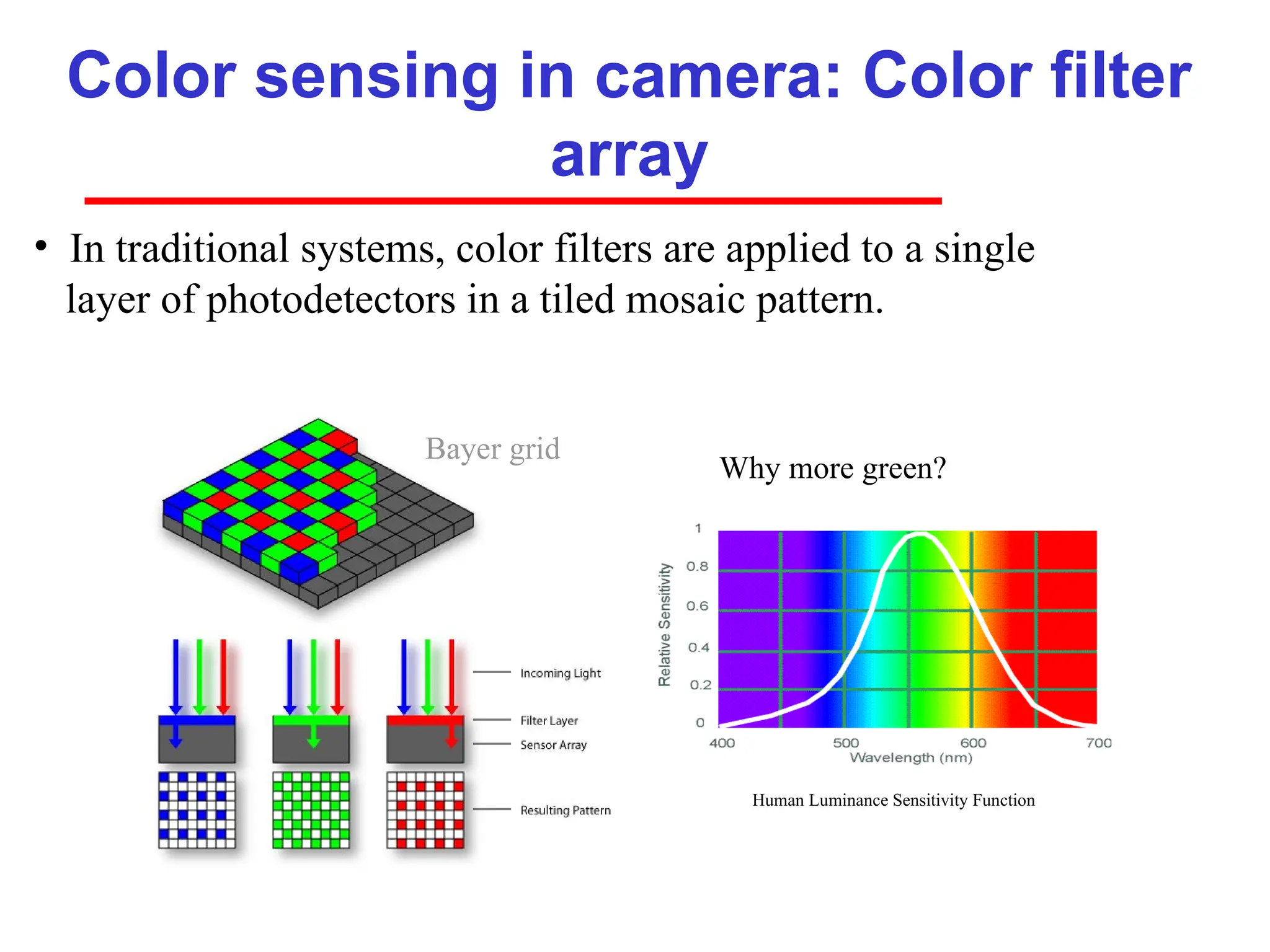
Color sensing incamera: Color filter
array
Why more green?
• In traditional systems, color filters are applied to a single
layer of photodetectors in a tiled mosaic pattern.
Human Luminance Sensitivity Function
Bayer grid
71.
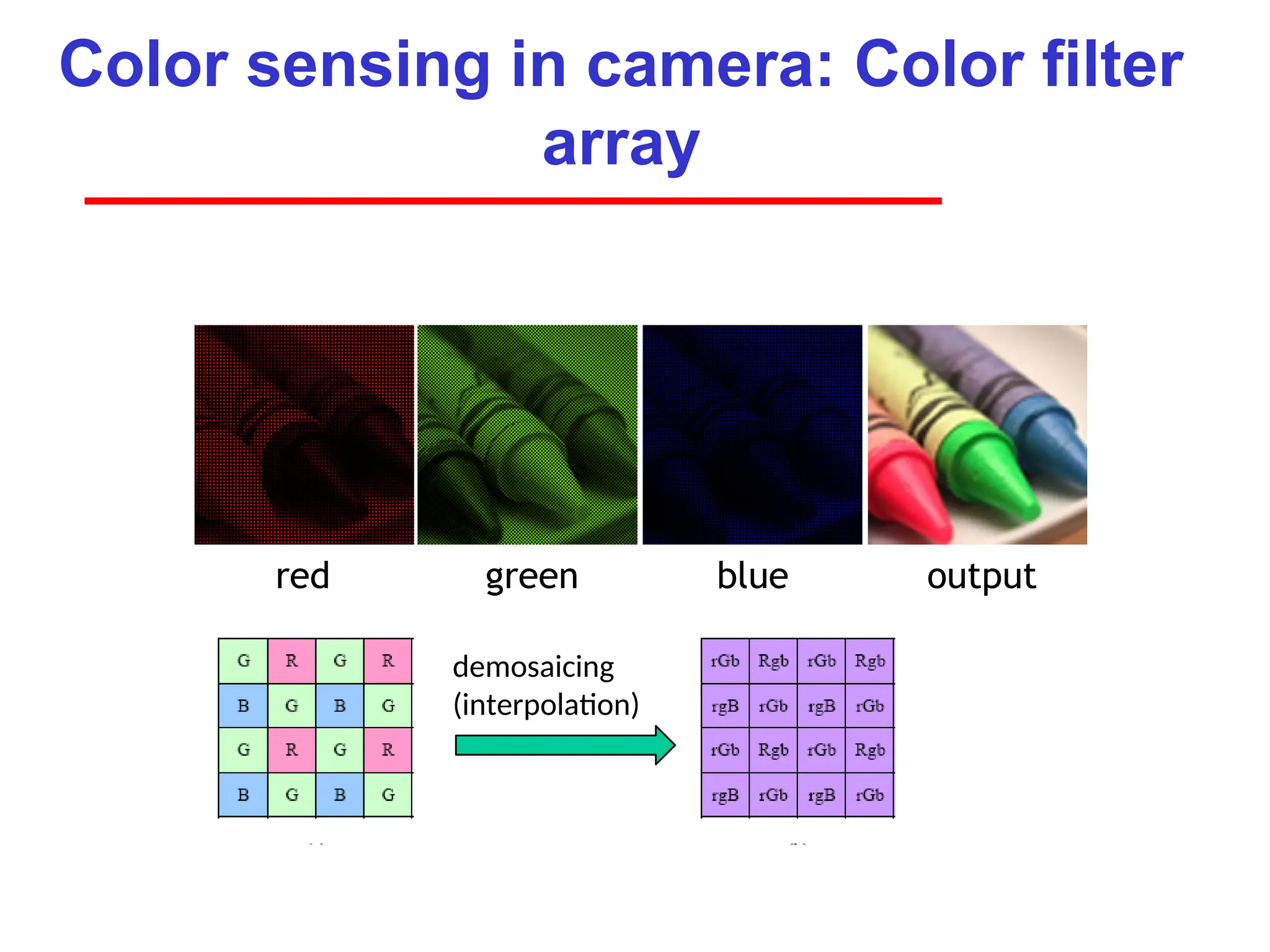
Color sensing incamera: Color filter
array
red green blue output
demosaicing
(interpolation)
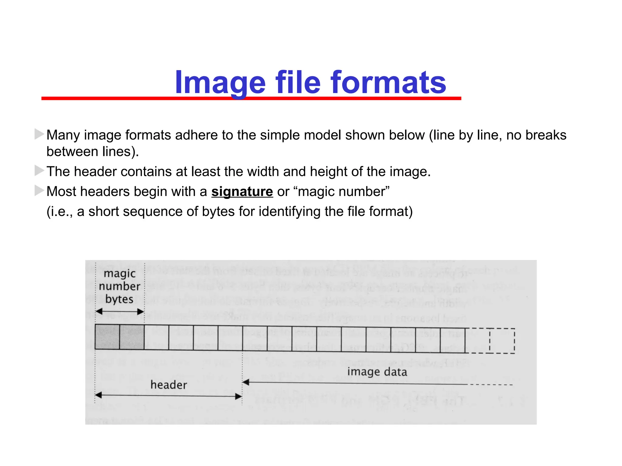
Image file formats
Manyimage formats adhere to the simple model shown below (line by line, no breaks
between lines).
The header contains at least the width and height of the image.
Most headers begin with a signature or “magic number”
(i.e., a short sequence of bytes for identifying the file format)
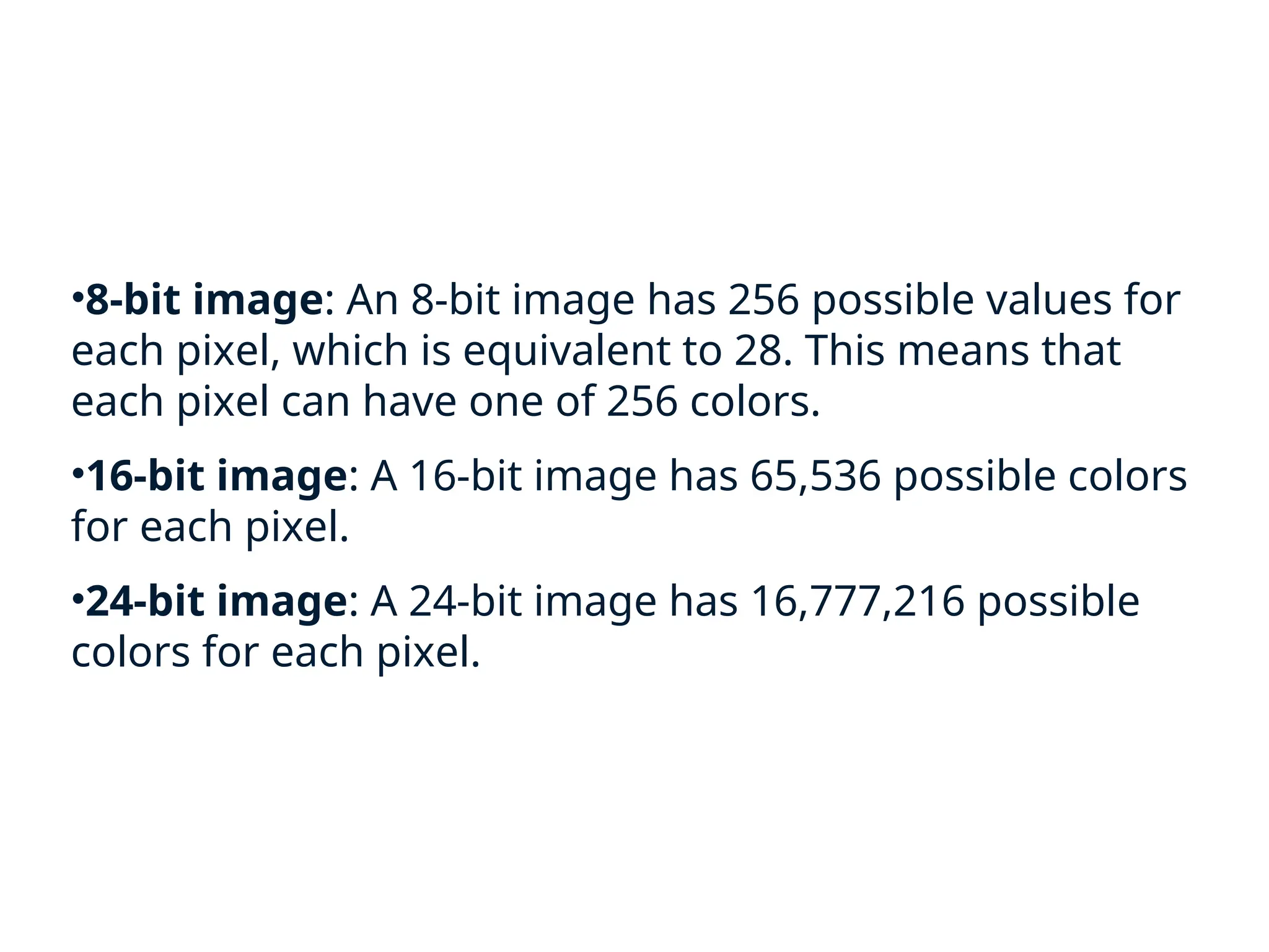
•8-bit image: An8-bit image has 256 possible values for
each pixel, which is equivalent to 28. This means that
each pixel can have one of 256 colors.
•16-bit image: A 16-bit image has 65,536 possible colors
for each pixel.
•24-bit image: A 24-bit image has 16,777,216 possible
colors for each pixel.