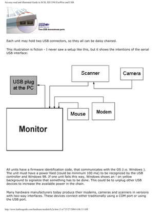
Downloaded 315 times


![KarbosGuide.com. Module 1a. About data.
With our electric switches, we can write 0 or 1. We can now start our data processing!
The PC is filled with these switches (in the form of transistors). There are literally millions of those in the
electronic components. Each represents either a 0 or a 1, so we can process data with millions of 0s and
1s.
Please click the banners to support our work!
Bits
[top]
Each 0 or 1 is called a bit. Bit is an abbreviation of the expression BInary digiT. It is called binary, since
it is derived from the binary number system:
0 1 bit
http://www.karbosguide.com/hardware/module1a1.htm (2 of 5)7/27/2004 4:05:11 AM](https://image.slidesharecdn.com/computerrepair-acompleteillustratedguidetopchardware-140318001250-phpapp01/85/Computer-repair-_a_complete_illustrated_guide_to_pc_hardware-5-320.jpg)
![KarbosGuide.com. Module 1a. About data.
1 1 bit
0110 4 bit
01101011 8 bit
The binary number system
[top]
The binary number system is made up of digits, just like our common decimal system (10 digit system).
But, while the decimal system uses digits 0 through 9, the binary system only uses digits 0 and 1.
If you are interested in understanding the binary number system, then here is a brief course. See if you
can follow the system. See how numbers are constructed in the binary system, using only 0s and 1s:
Numbers, as known in the
decimal-system
Same numbers in binary
system
0 0
1 1
2 10
3 11
4 100
5 101
6 110
7 111
8 1000
Digital data
[top]
http://www.karbosguide.com/hardware/module1a1.htm (3 of 5)7/27/2004 4:05:11 AM](https://image.slidesharecdn.com/computerrepair-acompleteillustratedguidetopchardware-140318001250-phpapp01/85/Computer-repair-_a_complete_illustrated_guide_to_pc_hardware-6-320.jpg)
![KarbosGuide.com. Module 1a. About data.
We have seen that the PC appears capable of handling data, if it can receive them as 0s and 1s. This
data format is called digital. If we can translate our daily data from their analog format to digital format,
they will appear as chains of 0s and 1s, then the PC can handle them.
So, we must be able to digitize our data. Pour text, sounds, and pictures into a funnel, from where they
emerge as 0s and 1s:
Let us see how this can be accomplished.
q Next page
q Previous page
Learn more [top]
Read more about the boot process and system bus in Module 2b
Read more about I/O buses in module 2c
Read more about the motherboard chip set in module 2d
Read more about RAM in module 2e
Read about EIDE in module 5b
[Main page] [Contact] [Karbo's Dictionary] [The Software Guides]
http://www.karbosguide.com/hardware/module1a1.htm (4 of 5)7/27/2004 4:05:11 AM](https://image.slidesharecdn.com/computerrepair-acompleteillustratedguidetopchardware-140318001250-phpapp01/85/Computer-repair-_a_complete_illustrated_guide_to_pc_hardware-7-320.jpg)
![KarbosGuide.com. Module 1a. About data.
"translation:"
Character Bit pattern Byte
number
Character Bit pattern Byte
number
A 01000001 65 ¼ 10111100 188
B 01000010 66 . 00101110 46
C 01000011 67 : 00111010 58
a 01100001 97 $ 00100100 36
b 01100010 98 01011100 92
o 01101111 111 ~ 01111110 126
p 01110000 112 1 00110001 49
q 01110001 113 2 00110010 50
r 01110010 114 9 00111001 57
x 01111000 120 © 10101001 169
y 01111001 121 > 00111110 62
z 01111010 122 ‰ 10001001 137
When you write the word "summer", you write 6 letters. If the computer has to process that
word, it will be digitized to 6 bytes. In other words, the word summer occupies 6 bytes in the
PC RAM, when you type it, and 6 bytes on the hard disk, if you save it.
ASCII
[top]
ASCII means American Standard Code for Information Interchange. It is an industry
standard, which assigns letters, numbers, and other characters within the 256 slots available
in the 8 bit code.
http://www.karbosguide.com/hardware/module1a2.htm (2 of 5)7/27/2004 4:05:22 AM](https://image.slidesharecdn.com/computerrepair-acompleteillustratedguidetopchardware-140318001250-phpapp01/85/Computer-repair-_a_complete_illustrated_guide_to_pc_hardware-10-320.jpg)
![KarbosGuide.com. Module 1a. About data.
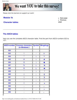
The ASCII table is divided in 3 sections:
q Non printable system codes between 0 and 31.
q "Lower ASCII" between 32 and 127. This part of the table originates from older, American
systems, which worked on 7 bit character tables. Foreign letters, like Ø and Ü were not
available then.
q "Higher ASCII" between 128 and 255. This part is programmable, in that you can
exchange characters, based on which language you want to write in. Foreign letters are
placed in this part.
Learn more about the ASCII table in Module 1b
An example
Let us imagine a stream of bits sent from the keyboard to the computer. When you type,
streams of 8 bits are sent to the computer. Let us look at a series of bits:
001100010011001000110011
Bits are combined into bytes (each 8 bits). These 24 bits are interpreted as three bytes. Let
us read them as bytes: 00110001, 00110010, and 00110011.
When we convert these byte binary numbers to decimal numbers, you will see that they read
as 49, 50, and 51 in decimal numbers. To interpret these numbers, we have to look at the
ASCII table. You will find that you have typed the numbers 1, 2, and 3.
About text and code
[top]
Now we have seen the PCs user data, which are always digitized. But there are many
different kinds of data in the PC. You can differentiate between 2 fundamental types of data:
q Program code, which is data, that allows the PC to function.
q User data, like text, graphics, sound.
The fact is, that the CPU must have instructions to function. You can read more about this in
the review of the CPU in module 3a. An instruction is a string of data, of 0s and 1s. The CPU
is designed to recognize these instructions, which arrive together with the user input data to
http://www.karbosguide.com/hardware/module1a2.htm (3 of 5)7/27/2004 4:05:22 AM](https://image.slidesharecdn.com/computerrepair-acompleteillustratedguidetopchardware-140318001250-phpapp01/85/Computer-repair-_a_complete_illustrated_guide_to_pc_hardware-11-320.jpg)
![KarbosGuide.com. Module 1a. About data.
be processed.
The program code is thus a collection of instructions, which are executed one by one, when
the program runs. Each time you click the mouse, or hit a key on the keyboard, instructions
are sent from your software (program) to the CPU, telling it what to do next.
User data are those data, which tells the software how to respond. The letters, illustrations,
home pages, etc., which you and I produce, are created with appropriate software.
Files
[top]
Both program code and user data are saved as files on the hard disk. Often, you can
recognize the type of file by its suffix. Here are some examples:
Content File name
Program code START.EXE, WIN.COM, HELP.DLL, VMM32.VXD
User data LETTER.DOC, HOUSE.BMP, INDEX.HTM
This is written as an introduction to naming files. The file name suffix determines how the PC
will handle the file. You can read about this subject in some of my books, e.g. "DOS - teach
yourself" (only available in Europe.
q Next page
q Previous page
Learn more [top]
Read more about the boot process and system bus in Module 2b
Read more about I/O buses in module 2c
Read more about the motherboard chip set in module 2d
Read more about RAM in module 2e
http://www.karbosguide.com/hardware/module1a2.htm (4 of 5)7/27/2004 4:05:22 AM](https://image.slidesharecdn.com/computerrepair-acompleteillustratedguidetopchardware-140318001250-phpapp01/85/Computer-repair-_a_complete_illustrated_guide_to_pc_hardware-12-320.jpg)
![KarbosGuide.com. Module 1a. About data.
Read about EIDE in module 5b
[Main page] [Contact] [Karbo's Dictionary] [The Software Guides]
Copyright (c) 1996-2001 by Michael B. Karbo. www.karbosguide.com.
http://www.karbosguide.com/hardware/module1a2.htm (5 of 5)7/27/2004 4:05:22 AM](https://image.slidesharecdn.com/computerrepair-acompleteillustratedguidetopchardware-140318001250-phpapp01/85/Computer-repair-_a_complete_illustrated_guide_to_pc_hardware-13-320.jpg)
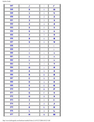
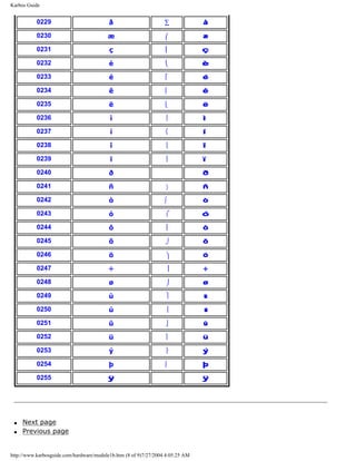
![Karbos Guide
078 N Ν N
079 O Ο O
080 P Π P
081 Q Θ Q
082 R Ρ R
083 S Σ S
084 T Τ T
085 U Υ U
086 V ς V
087 W Ω W
088 X Ξ X
089 Y Ψ Y
090 Z Ζ Z
091 [ [ [
092 ∴
093 ] ] ]
094 ^ ⊥ ^
095 _ _ _
096 ` `
097 a α a
098 b β b
099 c χ c
100 d δ d
101 e ε e
102 f φ f
103 g γ g
104 h η h
105 i ι i
106 j ϕ j
107 k κ k
108 l λ l
http://www.karbosguide.com/hardware/module1b.htm (3 of 9)7/27/2004 4:05:25 AM](https://image.slidesharecdn.com/computerrepair-acompleteillustratedguidetopchardware-140318001250-phpapp01/85/Computer-repair-_a_complete_illustrated_guide_to_pc_hardware-16-320.jpg)
![Karbos Guide
Learn more [top]
Read module 5a about expansion cards, where we evaluate the I/O buses from the port side.
Read module 5b about AGP and module 5c about Firewire.
Read module 7a about monitors, and 7b on graphics card.
Read module 7c about sound cards, and 7d on digital sound and music.
[Main page] [Contact] [Karbo's Dictionary] [The Software Guides]
Copyright (c) 1996-2001 by Michael B. Karbo. www.karbosguide.com.
http://www.karbosguide.com/hardware/module1b.htm (9 of 9)7/27/2004 4:05:25 AM](https://image.slidesharecdn.com/computerrepair-acompleteillustratedguidetopchardware-140318001250-phpapp01/85/Computer-repair-_a_complete_illustrated_guide_to_pc_hardware-22-320.jpg)
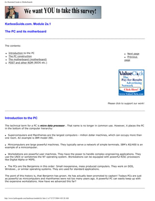
![An illustrated Guide to Motherboards
Please click the banners to support our work!
The PC's success [top]
The PC came out in 1981. In less than 20 years, it has totally changed our means of communicating. When the PC was
introduced by IBM, it was just one of many different micro data processors. However, the PC caught on. In 5-7 years,
it conquered the market. From being an IBM compatible PC, it became the standard.
If we look at early PCs, they are characterized by a number of features. Those were instrumental in creating the PC
success.
q The PC was from the start standardized and had an open architecture.
q It was well documented and had great possibilities for expansion.
q It was inexpensive, simple and robust (definitely not advanced).
The PC started as IBM's baby. It was their design, built over an Intel processor (8088) and fitted to Microsoft's simple
operating system MS-DOS.
Since the design was well documented, other companies entered the market. They could produce functionable copies
(clones) of the central system software (BIOS). The central ISA bus was not patented. Slowly, a myriad of companies
developed, manufacturing IBM compatible PCs and components for them.
The Clone was born. A clone is a copy of a machine. A machine, which can do precisely the same as the original (read
Big Blue - IBM). Some of the components (for example the hard disk) may be identical to the original. However, the
Clone has another name (Compaq, Olivetti, etc.), or it has no name at all. This is the case with "the real clones."
Today, we differentiate between:
q Brand names, PCs from IBM, Compaq, AST, etc. Companies which are so big, so they develop their own hardware
components.
q Clones, which are built from standard components. Anyone can make a clone.
Since the basic technology is shared by all PCs, I will start with a review of that.
The PC construction
[top]
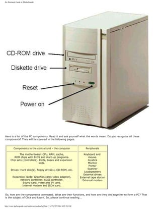
The PC consists of a central unit (referred to as the computer) and various peripherals. The computer is a box, which
contains most of the working electronics. It is connected with cables to the peripherals.
On these pages, I will show you the computer and its components. Here is a picture of the computer:
http://www.karbosguide.com/hardware/module2a1.htm (2 of 7)7/27/2004 4:05:28 AM](https://image.slidesharecdn.com/computerrepair-acompleteillustratedguidetopchardware-140318001250-phpapp01/85/Computer-repair-_a_complete_illustrated_guide_to_pc_hardware-24-320.jpg)
![An illustrated Guide to Motherboards
The von Neumann Model of the PC
[top]
Computers have their roots 300 years back in history. Mathematicians and philosophers like Pascal, Leibnitz, Babbage
and Boole made the foundation with their theoretical works. Only in the second half of this century was electronic
science sufficiently developed to make practical use of their theories.
The modern PC has roots that go back to the USA in the 1940s. Among the many scientists, I like to remember John
von Neumann (1903-57). He was a mathematician, born in Hungary. We can still use his computer design today. He
broke computer hardware down in five primary parts:
q CPU
q Input
q Output
q Working memory
q Permanent memory
Actually, von Neumann was the first to design a computer with a working memory (what we today call RAM). If we
apply his model to current PCs, it will look like this:
http://www.karbosguide.com/hardware/module2a1.htm (4 of 7)7/27/2004 4:05:28 AM](https://image.slidesharecdn.com/computerrepair-acompleteillustratedguidetopchardware-140318001250-phpapp01/85/Computer-repair-_a_complete_illustrated_guide_to_pc_hardware-26-320.jpg)
![An illustrated Guide to Motherboards
All these subjects will be covered.
Data exchange - the motherboard
[top]
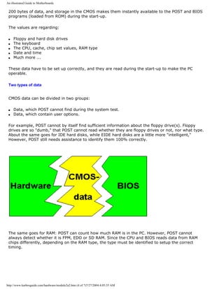
The ROM chips contain instructions, which are specific for that particular motherboard. Those programs and
instructions will remain in the PC throughout its life; usually they are not altered.
Primarily the ROM code holds start-up instructions. In fact there are several different programs inside the start-up
instructions, but for most users, they are all woven together. You can differentiate between:
q POST (Power On Self Test)
q The Setup instructions, which connect with the CMOS instructions
q BIOS instructions, which connect with the various hardware peripherals
q The Boot instructions, which call the operating system (DOS, OS/2, or Windows )
All these instructions are in ROM chips, and they are activated one by one during start-up. Let us look at each part.
The suppliers of system software
[top]
All PCs have instructions in ROM chips on the motherboard. The ROM chips are supplied by specialty software
manufacturers, who make BIOS chips. The primary suppliers are:
q Phoenix
q AMI ( American Megatrends )
q Award
You can read the name of your BIOS chip during start-up. You can also see the chip on the system board. Here is a
picture (slightly blurred) of an Award ROM chip:
http://www.karbosguide.com/hardware/module2a1.htm (5 of 7)7/27/2004 4:05:28 AM](https://image.slidesharecdn.com/computerrepair-acompleteillustratedguidetopchardware-140318001250-phpapp01/85/Computer-repair-_a_complete_illustrated_guide_to_pc_hardware-27-320.jpg)
![An illustrated Guide to Motherboards
Here is an AMI chip with BIOS and start-up instructions:
Let us look at the different components inside the ROM chip.
q Next page
q Previous page
Learn more [top]
Read more about the boot process and system bus in Module 2b
Read more about I/O buses in module 2c
Read more about the motherboard chip set in module 2d
Read more about RAM in module 2e
Read about EIDE in module 5b
I also recommend two books for further studies. Gunnar Forst: "PC Principles", from MIT is excellent. Also "The Winn
L. Rosch Hardware Bible" from Brady covers the same subjects. Also "PC Intern" from Abacus is fine.
Links to BIOS information:
Mr BIOS FAQ
http://www.karbosguide.com/hardware/module2a1.htm (6 of 7)7/27/2004 4:05:28 AM](https://image.slidesharecdn.com/computerrepair-acompleteillustratedguidetopchardware-140318001250-phpapp01/85/Computer-repair-_a_complete_illustrated_guide_to_pc_hardware-28-320.jpg)
![An illustrated Guide to Motherboards
[Main page] [Contact] [Karbo's Dictionary] [The Software Guides]
Copyright (c) 1996-2001 by Michael B. Karbo. www.karbosguide.com.
http://www.karbosguide.com/hardware/module2a1.htm (7 of 7)7/27/2004 4:05:28 AM](https://image.slidesharecdn.com/computerrepair-acompleteillustratedguidetopchardware-140318001250-phpapp01/85/Computer-repair-_a_complete_illustrated_guide_to_pc_hardware-29-320.jpg)
![An illustrated Guide to Motherboards
Please click the banners to support our work!
Click & Learn. Module 2a.2
The system software on the motherboard
The contents:
q The Setup program
q The POST
q The CMOS RAM
q Opening the Setup program
q Next page
q Previous page
Articles written
by Michael B. Karbo
The Setup programs [top]
There are three elements in the start-up part of the ROM chip:
q The Initializing routine, which sets up the BIOS functions. The adapter ROM is integrated. A
table covering all the BIOS programs is constructed. This is often called the interrupt vectors.
q The POST (the test programs)
q The disk bootstrap loader, which calls upon the operating system.
http://www.karbosguide.com/hardware/module2a2.htm (1 of 7)7/27/2004 4:05:35 AM](https://image.slidesharecdn.com/computerrepair-acompleteillustratedguidetopchardware-140318001250-phpapp01/85/Computer-repair-_a_complete_illustrated_guide_to_pc_hardware-30-320.jpg)
![An illustrated Guide to Motherboards
These programs are stored in the ROM chip, and they are activated one by one during the PC start-
up.
The POST
Power On Self Test is the first instruction executed during start-up. It checks the PC components
and that everything works. You can recognize it during the RAM test, which occurs as soon as you
turn power on.
You may follow the checks being executed in this order, as the information are gathered:
1) Information about the graphics adapter
2) Information about the BIOS (name, version)
3) Information about the RAM (being counted)
As users, we have only limited ability to manipulate the POST instructions. But certain system
boards enable the user to order a quick system check. Some enable the user to disable the RAM
test, thereby shortening the duration of the POST. The duration of the POST can vary considerably
in different PCs. On the IBM PC 300 computer, it is very slow. But you can disrupt it by pressing
[Esc].
Error messages
If POST detects errors in the system, it will write error messages on the screen. If the monitor is
not ready, or if the error is in the video card, it will also sound a pattern of beeps (for example 3
short and one long) to identify the error to the user. If you want to know more of the beeps, you
can find explanations on the Award, AMI and Phoenix web sites. For instance you will receive error
messages if the keyboard is not connected or if something is wrong with the cabling to the floppy
drive.
POST also reads those user data, which are found in the CMOS. This is discussed in the following
chapter.
The bootstrap loader
The last part of the BIOS execution at start-up is the bootstrap loader. It is a tiny program, which
only has one task: to find the bootsector on a disk (hard disk, floppy or another boot-drive).
The DOS Boot Record (DBR) also holds a media descriptor as well as information on the OS
version. Please read module 6a4 on this issue. You can use DiskEdit (included in the "Norton
Utilities") to read view the contents of the boot sector.
http://www.karbosguide.com/hardware/module2a2.htm (2 of 7)7/27/2004 4:05:35 AM](https://image.slidesharecdn.com/computerrepair-acompleteillustratedguidetopchardware-140318001250-phpapp01/85/Computer-repair-_a_complete_illustrated_guide_to_pc_hardware-31-320.jpg)
![An illustrated Guide to Motherboards
When the disk holds no boot strap routine, you get an error message like "Non-system disk,
replace with system disk and press any key".
The bootstrap loader is the last step in BIOS execution during start-up. It hands over the control to
the bootstrap routine found on the boot disk. The OS is being loaded.
CMOS RAM [top]
CMOS stands for Complementary Metal Oxide Semiconductor. In PC’s there is a small amount of
memory in a special CMOS RAM chip. The data is maintained with electric power from a small
battery.
CMOS is only a medium for storage. It could be used for any type of data. Here, it holds important
system data, values to be used during the start process. These information take up maybe 100 or
http://www.karbosguide.com/hardware/module2a2.htm (3 of 7)7/27/2004 4:05:35 AM](https://image.slidesharecdn.com/computerrepair-acompleteillustratedguidetopchardware-140318001250-phpapp01/85/Computer-repair-_a_complete_illustrated_guide_to_pc_hardware-32-320.jpg)
![An illustrated Guide to Motherboards
The configuration of CMOS data
The PC must be configured, be supplied with this information. That is done in the factory or store,
where it is assembled. This information is stored in CMOS, where they stay. CMOS data only need
to be updated, when different or additional hardware components are installed. This could be a
different type hard disk or floppy disks or an new RAM type. Often the user can do this him/herself.
Other data in CMOS contain various user options . This is data, which you can write to CMOS. For
example, you can adjust date and time, which the PC then adjusts every second. You can also
choose between different system parameters. Maybe you want a short system check instead of a
long one. Or if you want the PC to try to boot from hard disk C before trying floppy disk A, or vice
versa. These options can be written to CMOS.
Many of the options are of no interest to the ordinary user. These are options, which regard
controller chips on the motherboard, which can be configured in different ways. Ordinarily, there is
no need to make such changes. The motherboard manufacturer has already selected the optimal
configurations. They recommend in their manuals, that you do not change these default settings.
We can conclude, that CMOS data are essential system data, which are vital for operation of the
PC. Their special feature is, that they are user adjustable. Adjustments to CMOS are made during
start-up.
Opening the Setup program
[top]
You communicate with the BIOS programs and the CMOS memory through the so-called Setup
program. This gives us a very simple user interface to configuring the PC with these vital data.
Typically you reach the Setup program by pressing [Delete] immediately after you power up the
PC. That brings you to a choice of setup menus. You leave Setup by pressing [Esc], and choose "Y"
to restart the PC with the new settings. Generally, you should not change these settings, unless
http://www.karbosguide.com/hardware/module2a2.htm (5 of 7)7/27/2004 4:05:35 AM](https://image.slidesharecdn.com/computerrepair-acompleteillustratedguidetopchardware-140318001250-phpapp01/85/Computer-repair-_a_complete_illustrated_guide_to_pc_hardware-34-320.jpg)
![An illustrated Guide to Motherboards
you know precisely what you are doing.
Here you see the start menu of the American Megatrends BIOS Setup program, which has a kind of
graphical user interface. You are supposed to use the mouse:
q Next page
q Previous page
Learn more [top]
Read more about the boot process and system bus in Module 2b
Read more about I/O buses in module 2c
Read more about the motherboard chip set in module 2d
Read more about RAM in module 2e
Read about EIDE in module 5b
http://www.karbosguide.com/hardware/module2a2.htm (6 of 7)7/27/2004 4:05:35 AM](https://image.slidesharecdn.com/computerrepair-acompleteillustratedguidetopchardware-140318001250-phpapp01/85/Computer-repair-_a_complete_illustrated_guide_to_pc_hardware-35-320.jpg)
![An illustrated Guide to Motherboards
I also recommend two books for further studies. Gunnar Forst: "PC Principals", from MIT is
excellent. Also "The Winn L. Rosch Hardware Bible" from Brady covers the same subjects. Also "PC
Intern" from Abacus is fine.
Links to BIOS information:
BIOS Guide
Mr BIOS FAQ
[Main page] [Contact] [Karbo's Dictionary] [The Software Guides]
Copyright (c) 1996-2001 by Michael B. Karbo. www.karbosguide.com.
http://www.karbosguide.com/hardware/module2a2.htm (7 of 7)7/27/2004 4:05:35 AM](https://image.slidesharecdn.com/computerrepair-acompleteillustratedguidetopchardware-140318001250-phpapp01/85/Computer-repair-_a_complete_illustrated_guide_to_pc_hardware-36-320.jpg)
![An illustrated Guide to Motherboards
What can I use the Setup program for? [top]
The Setup program can do many things for you. However, be careful. You should not change any values
within the menus, unless you know what you are doing. Otherwise your PC may not function properly.
You have to enter Setup, if you install a different type or additional disk drive in your PC. Certain BIOSs
will also need adjustment of its settings, if a CDROM drive is installed on one of the EIDE channels.
The Standard values
The standard values in the CMOS Setup are used to configure:
q The date and time.
q The keyboard.
q The display.
q The diskette drive.
q EIDE units number 1-4 (typically hard disks and CD-ROM-drive).
The values for date and time are stored in the CMOS RAM. You can always change them, from Setup or
from DOS, Windows or any other OS.
The keyboard - obviously it has to be there. But it is possible to configure the PC to work without a
keyboard. Otherwise the PC will error if the keyboard is missing.
The display is always VGA. From older times the Setup gives you options as EGA, CGA and MDA. You
won't need them!
Diskette drive has to be selected. You can choose to have A: or B: or both. Each drive can be of five
http://www.karbosguide.com/hardware/module2a3.htm (2 of 6)7/27/2004 4:05:47 AM](https://image.slidesharecdn.com/computerrepair-acompleteillustratedguidetopchardware-140318001250-phpapp01/85/Computer-repair-_a_complete_illustrated_guide_to_pc_hardware-38-320.jpg)
![An illustrated Guide to Motherboards
types or more. You probably have the 1.44 MB floppy drive. You choose among the options using [PgUp]
and [PgDn]. Modern super floppies like Zip and LS120 are not to be installed as diskette drives, they are
EIDE units.
The hard disk is the most important unit to install in this part of the Setup. With the modern
motherboards and the EIDE drives you may experience an automatic configuration during the Auto
detect . In other situations you have to run the auto detect yourself. With older drives, you have to
enter all the CHS-values for the drive (number of cylinders, heads and sectors.
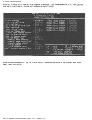
The BIOS Feature Setup
The Feature Setup is the next layer in the CMOS setup. Here you can choose among options like:
q Quick execution of POST (a good thing).
q Choice of boot device EIDE/SCSI. If you have both types of hard drives, which one is to be booted?
q The boot sequence.
q ....
Modifying the boot sequence
You can change the boot sequence from A:, C: to C:, A:. That means, that the PC will not try to boot
from any diskette in the A drive. This will protect you from certain virus attacks from the boot sector.
Also, the boot process will not be blocked by any diskette in the A drive. If you need to boot from A-
drive (for example, if you want to install Windows 98), you have to enter Setup again, and change the
boot sequence to A:, C:. That is no problem.
Power Management
You also use the Setup program to regulate the power management , which is the power saving
features in the motherboard. For example, you can make the CPU shut down after one minute of no
activity. There are plenty of settings available in this area. The power management functions found on
the PC’s motherboard will cooperate with the operating system. Especially Windows 98 is very good at
using the power management.
Password Protection
You can protect the Setup program with a password. This is used widely in schools, where the teachers
do not want the little nerds to make changes in the setup. Please remember the password (write it down
in the motherboard manual). If you forget it you have to remove the battery from the motherboard.
Then all user input to the CMOS is erased - including the password.
Images from the Setup program
[top]
http://www.karbosguide.com/hardware/module2a3.htm (3 of 6)7/27/2004 4:05:47 AM](https://image.slidesharecdn.com/computerrepair-acompleteillustratedguidetopchardware-140318001250-phpapp01/85/Computer-repair-_a_complete_illustrated_guide_to_pc_hardware-39-320.jpg)
![An illustrated Guide to Motherboards
q Next page
q Previous page
Learn more [top]
Module 2b. About the boot process and system bus
Read more about I/O buses in module 2c
Read more about the motherboard chip set in module 2d
Read more about RAM in module 2e
Read about EIDE in module 5b
I also recommend two books for further studies. Gunnar Forst: "PC Principals", from MIT is excellent.
Also "The Winn L. Rosch Hardware Bible" from Brady covers the same subjects. Also "PC Intern" from
Abacus is fine.
Links to BIOS information:
http://www.karbosguide.com/hardware/module2a3.htm (5 of 6)7/27/2004 4:05:47 AM](https://image.slidesharecdn.com/computerrepair-acompleteillustratedguidetopchardware-140318001250-phpapp01/85/Computer-repair-_a_complete_illustrated_guide_to_pc_hardware-41-320.jpg)
![An illustrated Guide to Motherboards
BIOS Guide
Mr BIOS FAQ
[Main page] [Contact] [Karbo's Dictionary] [The Windows 98 pages]
Copyright (c) 1996-2001 by Michael B. Karbo. www.karbosguide.com.
http://www.karbosguide.com/hardware/module2a3.htm (6 of 6)7/27/2004 4:05:47 AM](https://image.slidesharecdn.com/computerrepair-acompleteillustratedguidetopchardware-140318001250-phpapp01/85/Computer-repair-_a_complete_illustrated_guide_to_pc_hardware-42-320.jpg)
![An illustrated Guide to Motherboards
KarbosGuide.com. Module 2a.4.
The system software of hardware
The contents:
q Next page
q Previous page
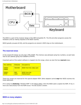
The BIOS in adapter ROM
[top]
During the start-up process the BIOS programs are read from the ROM circuits. BIOS stands for Basic Input
Output System and it is small program routines which controls specific hardware units.
For instance you have a BIOS routine which reads the keyboard:
http://www.karbosguide.com/hardware/module2a4.htm (1 of 4)7/27/2004 4:05:55 AM](https://image.slidesharecdn.com/computerrepair-acompleteillustratedguidetopchardware-140318001250-phpapp01/85/Computer-repair-_a_complete_illustrated_guide_to_pc_hardware-43-320.jpg)
![An illustrated Guide to Motherboards
There are BIOS codes on many adapters (expansion cards). The adapters are external hardware, which are
connected to and “integrated” with the motherboard during the hardware configuration and internalizing.
The adapters hold their own BIOS code making them functional. This BIOS must be included during the
configuration. Therefore, the adapter ROM is read during start-up, and the program code is “woven” together
with other BIOS programs and the CMOS data. It is all written into RAM, where it is ready for the operating
system, as you can see here:
The BIOS routines are not always in use. They can be regarded as basic program layers in the PC, giving it a
simple functionality.
Many programs routinely bypass BIOS. In that case, they "write direct to hardware", as we say. Windows
contains program files, which can be written directly to all kinds of hardware - bypassing BIOS routines. One
example is the COM ports. If you use the BIOS routines connected with them, you can transmit only at max.
9600 baud on the modem. That is insufficient. Therefore, Windows will assume control over the COM port.
BIOS update
BIOS programs can be updated . The modern motherboard has the BIOS instructions in flash ROM, which can be
updated. You can get new BIOS software from your supplier or on the Internet, which can be read onto the
motherboard. The loading is a special process, where you might need to change a jumper switch on the
motherboard. Usually, you do not need to do this, but it is a nice available option.
ATX motherboards [top]
The latest PC electronic standard is called ATX. It consists of a new type motherboard with a specific physical
design like the traditional board (30.5 cm X 19 cm). However the board has been shifted 90 degrees for a better
http://www.karbosguide.com/hardware/module2a4.htm (3 of 4)7/27/2004 4:05:55 AM](https://image.slidesharecdn.com/computerrepair-acompleteillustratedguidetopchardware-140318001250-phpapp01/85/Computer-repair-_a_complete_illustrated_guide_to_pc_hardware-45-320.jpg)
![An illustrated Guide to Motherboards
placing of the units.
The I/O connectors COM1, COM2 and LPT, keyboard, mouse and USB are mounted directly on the motherboard.
The ATX board requires specifically designed chassises with an I/O access opening measuring 1¾ by 6¼ inch.
ATX is designed by Intel, but has gained general acceptance.
The ATX motherboard is more ”intelligent” than the ordinary type. In a few years, it will be wide spread. It
includes advanced control facilities, where the BIOS program continually checks the CPU temperature and
voltages, the cooling fans RPM, etc. If over heating occurs, the PC will shut down automatically. The PC can also
be turned on by for example modem signals, since the power supply is controlled by the motherboard. The on/off
button will turn the PC "down" without turning it completely off.
If you want a PC designed for the future, the ATX layout is what you should go for.
q Next page
q Previous page
Learn more [top]
Module 2b. About the boot process and system bus
Read more about I/O buses in module 2c
Read more about the motherboard chip set in module 2d
Read more about RAM in module 2e
Read about EIDE in module 5b
I also recommend two books for further studies. Gunnar Forst: "PC Principals", from MIT is excellent. Also "The
Winn L. Rosch Hardware Bible" from Brady covers the same subjects. Also "PC Intern" from Abacus is fine.
Links to BIOS information:
BIOS Guide
Mr BIOS FAQ
[Main page] [Contact] [Karbo's Dictionary] [The Windows 98 pages]
Copyright (c) 1996-2001 by Michael B. Karbo. www.karbosguide.com.
http://www.karbosguide.com/hardware/module2a4.htm (4 of 4)7/27/2004 4:05:55 AM](https://image.slidesharecdn.com/computerrepair-acompleteillustratedguidetopchardware-140318001250-phpapp01/85/Computer-repair-_a_complete_illustrated_guide_to_pc_hardware-46-320.jpg)
![An illustrated Guide to the PC System BUS
KarbosGuide.com. Module 2b1.
About the System Bus
In this module, you can read about the following subjects, which add to our tour of the PC:
q The boot process
q Data on the motherboard
q Next page
q Previous page
The boot process [top]
The last step in the PC start-up is reading the operating system. The start-up program is instructed to
find the Master Boot Record. This is located in the very first sector on either hard disk (C) or floppy
drive A. From the MBR it reads the boot-strap which points to the location of the startup files of the
Operating System.
By default, the PC will look for a boot sector in floppy drive A. That is why the PC "drops dead" if there is
a different diskette in A drive. If there is no diskette in A drive, the start-up program will search for the
boot sector on hard drive C. When the boot sector is found, a small program segment (boot-strap) is
read from there. The boot-strap then takes over control of the PC. The start-up program has done its
job. Now DOS, Windows , or another operating system takes control.
Read more about boot sectors, etc. in module 6a, which deals with file systems.
Here is an illustration of the start-up process:
http://www.karbosguide.com/hardware/module2b1.htm (1 of 4)7/27/2004 4:05:57 AM](https://image.slidesharecdn.com/computerrepair-acompleteillustratedguidetopchardware-140318001250-phpapp01/85/Computer-repair-_a_complete_illustrated_guide_to_pc_hardware-47-320.jpg)
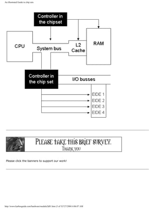
![An illustrated Guide to the PC System BUS
The data flow on the motherboard
[top]
On the motherboard, you will find the CPU, which is the "brain" of the PC and the buses. The buses are
the nerve system of the motherboard. They connect the CPU to all the other components. There are at
least three buses, which you can see below. You can read more about those on the following pages.
The buses are the PC's expressways. They are "wires" on the circuit board, which transmit data between
different components.
One "wire" can move one bit at a time. In the following text, we start from a typical Pentium board. We
will look at buses, chip sets and CPUs. Here is an illustration of some of the motherboard "logic." You
can print it:
http://www.karbosguide.com/hardware/module2b1.htm (2 of 4)7/27/2004 4:05:57 AM](https://image.slidesharecdn.com/computerrepair-acompleteillustratedguidetopchardware-140318001250-phpapp01/85/Computer-repair-_a_complete_illustrated_guide_to_pc_hardware-48-320.jpg)
![An illustrated Guide to the PC System BUS
q Next page
q Previous page
Learn more [top]
Read more about the motherboards chip set in module 2d
Read more about RAM in module 2e
[Main page] [Contact] [Karbo's Dictionary] [The Software Guides]
http://www.karbosguide.com/hardware/module2b1.htm (3 of 4)7/27/2004 4:05:57 AM](https://image.slidesharecdn.com/computerrepair-acompleteillustratedguidetopchardware-140318001250-phpapp01/85/Computer-repair-_a_complete_illustrated_guide_to_pc_hardware-49-320.jpg)
![An illustrated Guide to the PC System BUS
KarbosGuide.com. Module 2b2.
About the System Bus
In this module, you can read about the following subjects, which add to our tour of the PC:
q PC buses, an intro
q The system bus
q 66 MHz bus
q 100 MHz bus
q Next page
q Previous page
Introduction to the PC buses
[top]
The PC receives and sends its data from and to buses. They can be divided into:
q The system bus, which connects the CPU with RAM
q I/O buses, which connect the CPU with other components.
http://www.karbosguide.com/hardware/module2b2.htm (1 of 6)7/27/2004 4:05:59 AM](https://image.slidesharecdn.com/computerrepair-acompleteillustratedguidetopchardware-140318001250-phpapp01/85/Computer-repair-_a_complete_illustrated_guide_to_pc_hardware-51-320.jpg)
![An illustrated Guide to the PC System BUS
The point is, that the system bus is the central bus. Actually, it
connects to the I/O buses, as you can see in this illustration. It is not
completely correct, since the architecture is much more complex, but
it shows the important point, that the I/O-buses usually derive from
the system bus:
You see the central system bus, which connects the CPU with RAM. A bridge connects the I/O
buses with the system bus and on to RAM. The bridge is part of the PC chip set, which will be
covered in module 2c.
3 different I/O buses
[top]
The I/O buses move data. They connect all I/O devices with the CPU and RAM. I/O devices
are those components, which can receive or send data (disk drives, monitor, keyboard, etc. ).
In a modern Pentium driven PC, there are two or three different I/O buses:
q The ISA bus, which is oldest, simplest, and slowest bus.
q The PCI bus, which is the fastest and most powerful bus.
q The USB bus, which is the newest bus. It may in the long run replace the ISA bus.
The three I/O buses will be described later. Here, we will take a closer look at the PC's
http://www.karbosguide.com/hardware/module2b2.htm (2 of 6)7/27/2004 4:05:59 AM](https://image.slidesharecdn.com/computerrepair-acompleteillustratedguidetopchardware-140318001250-phpapp01/85/Computer-repair-_a_complete_illustrated_guide_to_pc_hardware-52-320.jpg)
![An illustrated Guide to the PC System BUS
fundamental bus, from which the others are branches from.
The system bus
[top]
The system bus connects the CPU with RAM and maybe a buffer memory (L2-cache). The
system bus is the central bus. Other buses branch off from it.
The system bus is on the motherboard. It is designed to match a specific type of CPU.
Processor technology determines dimensioning of the system bus. At the same time, it has
taken much technological development to speed up "traffic" on the motherboard. The faster
the system bus gets, the faster the remainder of the electronic components must be..
The following three tables show different CPUs and their system buses:
Older CPUs System bus width System bus
speed
8088 8 bit 4.77 MHz
8086 16 bit 8 MHz
80286-12 16 bit 12 MHz
80386SX-16 16 bit 16 MHz
80386DX-25 32 bit 25 MHz
We see, that system bus speed follows the CPU's speed limitation. First at the fourth
generation CPU 80486DX2-50 are doubled clock speeds utilized. That gives the CPU a higher
internal clock frequency. The external clock frequency, used in the system bus, is only half of
the internal frequency:
CPUs in the 80486 family System bus width System bus
speed
80486SX-25 32 bit 25 MHz
80486DX-33 32 bit 33 MHz
80486DX2-50 32 bit 25 MHz
80486DX-50 32 bit 50 MHz
http://www.karbosguide.com/hardware/module2b2.htm (3 of 6)7/27/2004 4:05:59 AM](https://image.slidesharecdn.com/computerrepair-acompleteillustratedguidetopchardware-140318001250-phpapp01/85/Computer-repair-_a_complete_illustrated_guide_to_pc_hardware-53-320.jpg)
![An illustrated Guide to the PC System BUS
80486DX2-66 32 bit 33 MHz
80486DX4-100 32 bit 40 MHz
5X86-133 32 bit 33 MHz
66 MHz bus
[top]
For a long time all Pentium based computers ran at 60 or 66 MHz on the system bus, which is
64 bit wide:
CPUs in the
Pentium family
System bus width System bus
speed
Intel P60 64 bit 60 MHz
Intel P100 64 bit 66 MHz
Cyrix 6X86 P133+ 64 bit 55 MHz
AMD K5-133 64 bit 66 MHz
Intel P150 64 bit 60 MHz
Intel P166 64 bit 66 MHz
Cyrix 6X86 P166+ 64 bit 66 MHz
Pentium Pro 200 64 bit 66 MHz
Cyrix 6X86 P200+ 64 bit 75 MHz
Pentium II 64 bit 66 MHz
100 MHz bus
The speed of the system bus has increased in 1998. Using PC100 SDRAM a speed of 100 MHz
is well proven and the use of RDRAM will give us much higher speeds.
However the rise from 66 MHz to 100 MHz has the greatest impact on Socket 7 CPUs and
http://www.karbosguide.com/hardware/module2b2.htm (4 of 6)7/27/2004 4:05:59 AM](https://image.slidesharecdn.com/computerrepair-acompleteillustratedguidetopchardware-140318001250-phpapp01/85/Computer-repair-_a_complete_illustrated_guide_to_pc_hardware-54-320.jpg)
![An illustrated Guide to the PC System BUS
Learn more [top]
Read more about the motherboards chip set in module 2d
Read more about RAM in module 2e
[Main page] [Contact] [Karbo's Dictionary] [The Software Guides]
Copyright (c) 1996-2001 by Michael B. Karbo. www.karbosguide.com.
http://www.karbosguide.com/hardware/module2b2.htm (6 of 6)7/27/2004 4:05:59 AM](https://image.slidesharecdn.com/computerrepair-acompleteillustratedguidetopchardware-140318001250-phpapp01/85/Computer-repair-_a_complete_illustrated_guide_to_pc_hardware-56-320.jpg)
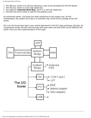
![An illustrated Guide to I/O-buses
Introduction to the I/O buses [top]
We have seen before, that the PC's buses are the fundamental data
"highways" on the system board. The "first" bus is the system bus,
which connects the CPU with RAM. In older designs it was a local bus.
In newer designs this bus is called the front side bus (FSB).
The typical local bus has a speed and width depending on the type
CPU installed on the motherboard. Typically, the system bus will be
64 bits wide and run at 66, 100 or 133 MHz. These high speeds create
electrical noises and other problems. Therefore, the speed must be
reduced for data reaching the expansion cards and other more
peripheral components.
Very few expansion cards can operate at more than 40 MHz. Then the electronics shut down.
The chips can just not react faster. Therefore, the PC has additional buses.
Originally only one bus
However, the first PCs had only one bus, which was common for the CPU, RAM and I/O
components:
The older first and second generation CPUs ran at relatively low clock frequencies, and all
system components could keep up with those speeds.
RAM on adapters
Among other things, that allowed additional RAM to be installed in expansion slots in the PC,
http://www.karbosguide.com/hardware/module2c1.htm (2 of 7)7/27/2004 4:06:02 AM](https://image.slidesharecdn.com/computerrepair-acompleteillustratedguidetopchardware-140318001250-phpapp01/85/Computer-repair-_a_complete_illustrated_guide_to_pc_hardware-58-320.jpg)
![An illustrated Guide to I/O-buses
by installing an adapter in a vacant expansion slot. An adapter, where RAM was mounted:
This setup would be unthinkable today. However it is truely a local bus. All units are united
on one bus using the same clock.
First in 1987, Compaq figured out how to separate system bus from I/O bus, so they could
run at different speeds. This multi-bus architecture has been industry standard ever since.
Modern PCs also have more than one I/O bus.
What does an I/O bus do?
[top]
I/O buses connect the CPU to all other components, except RAM. Data are moved on the
buses from one component to another, and data from other components to the CPU and RAM.
The I/O buses differ from the system bus in speed. Their speed will always be lower than the
system bus speed. Over the years, different I/O buses have been developed. On modern PCs,
you will usually find four buses:
http://www.karbosguide.com/hardware/module2c1.htm (3 of 7)7/27/2004 4:06:02 AM](https://image.slidesharecdn.com/computerrepair-acompleteillustratedguidetopchardware-140318001250-phpapp01/85/Computer-repair-_a_complete_illustrated_guide_to_pc_hardware-59-320.jpg)
![An illustrated Guide to I/O-buses
The physical aspects of the I/O buses
[top]
Physically, the I/O bus consists of tracks on the printed circuit board. These tracks are used
as:
q Data tracks, which each can move one bit at a time
q Address tracks, which identify where data should be sent to
q Other tracks for clock ticks, voltage, verification signals, etc.
When data are sent on the bus, they must be supplied with a receiver. Therefore, each device
on the bus has an address. Similarly, the RAM is divided in sections, each having its address.
Prior to sending data, a number is sent on the address track, to identify where the data
should be sent to.
The bus width
The number of data tracks determine the data transfer capacity. The ISA bus is slow, partly
because it only has 16 data tracks. The modern PCs send 32 bits per clock tick. On the ISA
bus, 32 bits must be divided in two packages of 16 bits. This delays the data transfer.
Another I/O bus concept is wait states.
Wait states
Wait states are small pauses. If an ISA adapter cannot keep up with the incoming data flow,
its controller sends wait states to the CPU. Those are signals to the CPU to "hold on for a
sec." A wait state is a wasted clock tick. The CPU skips a clock tick, when not occupied. Thus
the old and slow ISA adapter can significantly reduce the operating speed of a modern
computer.
Another aspect is the IRQ signals, which the components use to attract attention from the
CPU. That and the concepts DMA and bus mastering, are described in module 5, which deals
with adapters.
Technical and historical background for the I/
O buses [top]
In modern PCs you only find the PCI and ISA buses (besides USB, which we do not know
http://www.karbosguide.com/hardware/module2c1.htm (5 of 7)7/27/2004 4:06:02 AM](https://image.slidesharecdn.com/computerrepair-acompleteillustratedguidetopchardware-140318001250-phpapp01/85/Computer-repair-_a_complete_illustrated_guide_to_pc_hardware-61-320.jpg)
![An illustrated Guide to I/O-buses
much about yet). But, over the years, there have been other buses. Here is a diagram of the
various I/O buses. Then comes a more detailed description of each of the buses:
Bus
Year Bus width Bus speed
Max. throughput
(theoretical)
PC and XT 1980-82 8 bit
Synchronous with CPU:
4.77 - 6 MHz
4-6 MBps
ISA (AT)
Simple bus.
1984 16 bit Synchronous:
8-10 MHz
8 MBps
MCA. Advanced,
intelligent bus by IBM.
1987 32 bit Asynchronous:
10.33 MHz
40 MBps
EISA.
Bus for servers.
1988 32 bit Synchronous:
max. 8 MHz
32 MBps
VL. High speed bus,
used in 486s.
1993 32 bit Synchronous:
33-50 MHz
100-160
MBps
PCI. Intelligent,
advanced high speed
bus.
1993 32 bit Asynchronous:
33 MHz
132 MBps
USB. Modern, simple,
and intelligent bus.
1996 Serial 1.2 MBps
FireWire (IEEE1394).
High-speed I/O bus for
storage, video etc.
1999 Serial 80 MBps
USB 2.0 2001 Serial 12-40 MBps
SCSI is another type of bus.
q Next page
q Previous page
Learn more [top]
5c about the modern I/O bus called USB.
http://www.karbosguide.com/hardware/module2c1.htm (6 of 7)7/27/2004 4:06:02 AM](https://image.slidesharecdn.com/computerrepair-acompleteillustratedguidetopchardware-140318001250-phpapp01/85/Computer-repair-_a_complete_illustrated_guide_to_pc_hardware-62-320.jpg)
![An illustrated Guide to I/O-buses
Read module 5b about AGP and module 5c about Firewire.
Read more about chip sets on the motherboard in module 2d
Read about RAM in module 2e
Read Module 4b about hard disks.
Read Module 4c about optical media (CDROM and DVD).
Read Module 4d about super diskette and MO drives.
Read module 5a about expansion cards, where we evaluate the I/O buses from the port side.
Read module 7a about monitors, and 7b on graphics card.
Read module 7c about sound cards, and 7d on digital sound and music.
[Main page] [Contact] [Karbo's Dictionary] [The Software Guides]
Copyright (c) 1996-2001 by Michael B. Karbo. www.karbosguide.com.
http://www.karbosguide.com/hardware/module2c1.htm (7 of 7)7/27/2004 4:06:02 AM](https://image.slidesharecdn.com/computerrepair-acompleteillustratedguidetopchardware-140318001250-phpapp01/85/Computer-repair-_a_complete_illustrated_guide_to_pc_hardware-63-320.jpg)
![An illustrated Guide to I/O-buses
The ISA bus can be a tease, when you install new expansion cards (for example a sound card). Many of these
problems derive from the tuning of IRQ and DMA, which must be done manually on the old ISA bus.
Every component occupies a specific IRQ and possibly a DMA channel. That can create conflict with existing
components. Read module 5 about expansion cards and these problems.
The ISA bus is out
As described, the ISA bus is quite outdated and should not be used in modern pcs. There is a good chance, that
this "outdated legacy technology" (quoting Intel) will disappear completely.
The USB bus is the technology that will replace it. It has taken many years to get this working and accepted, but it
works now.
Intel's chip set 810 was the first not to include ISA support.
MCA, EISA and VLB [top]
In the 80s, a demand developed for buses more powerful than the ISA. IBM developed the
MCA bus and Compaq and others responded with the EISA bus. None of those were
particularly fast, and they never became particularly successful outside the server market.
Please support our
sponsor.
MCA
IBM's top of the line bus from 1987 is named Micro Channel Architecture. The MCA bus was a masterpiece, unifying
the best bus technology from the mainframe design with the demands from the PC. However, contrary to the ISA
bus, MCA is patented, and IBM demanded high royalty fees, when other PC manufacturers wanted to use it. Thus
the bus never became a great success, despite its advanced design. It ended up being a classic example of poor
marketing strategy.
The MCA bus is 32 bit wide and "intelligent." The cards configure themselves with respect to IRQ. Thus, they can
be installed without adjustments of jumper switches or other features. It works constantly at 10.33 MHz,
asynchronous with the system bus.
The MCA bus is also relatively fast with transfer rates of up to 40 MBps in 32 bit mode at 10.33 MHz. MCA requires
special adapters. There have never been too many adapters developed, since this bus is by and large used only in
IBM's own PCs.
EISA
EISA is a bus from 1988-89. It is designed by the "Gang of Nine:" the companies AST, Compaq, Epson, Hewlett-
Packard, NEC, Olivetti, Tandy, Wyse and Zenith. It came in response to IBM's patented MCA bus.
EISA is built on the ISA bus; the connector has the same dimensions and old ISA cards fit into the slots. To keep
this compatibility, the EISA bus works at maximum 8 MHz. Like ISA, the bus bus is synchronous with the CPU at a
clock frequency reduced to a fraction of the system bus clock frequency.
http://www.karbosguide.com/hardware/module2c2.htm (3 of 5)7/27/2004 4:06:04 AM](https://image.slidesharecdn.com/computerrepair-acompleteillustratedguidetopchardware-140318001250-phpapp01/85/Computer-repair-_a_complete_illustrated_guide_to_pc_hardware-66-320.jpg)
![An illustrated Guide to I/O-buses
EISA is compatible with ISA in the sense that ISA adapters can be installed in EISA slots. The EISA adapters hold a
second level of connectors in the button of the slot.
However, EISA is much more intelligent than ISA. It has bus mastering, divided interrupts and self configuration. It
is 32 bit wide, and with it's compressed transfers and BURST modegives a highly improved performance.
But, like the MCA, it did not have great success. The EISA bus is still used in some servers.
Vesa Local Bus
This Bus called VLB for short. It is an inexpensive and simple technology. This bus only achieved status as an
interim phenomenon (in 1993-94). VLB was widely used on 486 motherboards, where the system bus runs at 33
MHz. VLB runs directly with the system bus. Therefore, data transfer is at CPU speed, synchronous and in width.
The problem with VLB was compatibility. Adapters and system system boards would not always work together.
Vesa is an organization with about 120 members, mostly monitor and graphics card manufacturers. Therefore,
most VLB cards were video cards.
q Next page
q Previous page
Learn more [top]
Read module 5c about the modern I/O bus called USB.
Read module 5a about expansion cards, where we evaluate the I/O buses from the port side.
Read module 5b about AGP and module 5c about Firewire
Read more about chip sets on the motherboard in module 2d.
Read more about RAM in module 2e.
Read Module 4b about hard disks.
Read Module 4c about optical media (CDROM and DVD).
Read Module 4d about super diskette and MO drives.
Read module 7a about monitors, and 7b on graphics card.
Read module 7c about sound cards, and 7d on digital sound and music.
[Main page] [Contact] [Karbo's Dictionary] [The Software Guides]
http://www.karbosguide.com/hardware/module2c2.htm (4 of 5)7/27/2004 4:06:04 AM](https://image.slidesharecdn.com/computerrepair-acompleteillustratedguidetopchardware-140318001250-phpapp01/85/Computer-repair-_a_complete_illustrated_guide_to_pc_hardware-67-320.jpg)
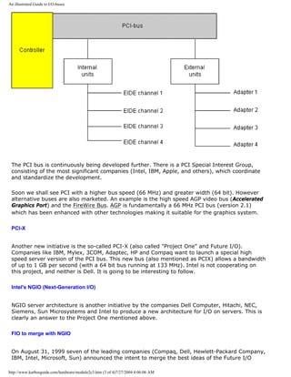
![An illustrated Guide to I/O-buses
KarbosGuide.com. Module 2c.3
About the PCI bus
The contents:
q Introducing the PCI bus
q The internal and external face.
q The future design
q NGIO
q Next page
q Previous page
Introducing the PCI bus
[top]
The PCI is the high speed bus of the 1990s. PCI stands for Peripheral
Component Interconnect. This bus is made by Intel. It is used today in
all PCs and other computers for connecting adapters, such as network-
controllers, graphics cards, sound cards etc.
Please support our
sponsor.
Some graphics cards however use the AGP-bus, which is a separate bus only intended for
graphics.
http://www.karbosguide.com/hardware/module2c3.htm (1 of 4)7/27/2004 4:06:06 AM](https://image.slidesharecdn.com/computerrepair-acompleteillustratedguidetopchardware-140318001250-phpapp01/85/Computer-repair-_a_complete_illustrated_guide_to_pc_hardware-69-320.jpg)
![An illustrated Guide to I/O-buses
(FIO) and Next Generation I/O (NGIO). The new open input/output architecture will find use in
servers. The bandwidth will be up to 6 GByte/sec.
The new standard NGIO will hardly go into production before 2001.
q Next page
q Previous page
Learn more [top]
Read module 5a about expansion cards, where we evaluate the I/O buses from the port side.
Read module 5b about AGP and module 5c about Firewire.
Read about chip sets on the motherboard in module 2d
Read more about RAM in module 2e
Read Module 4b about hard disks.
Read Module 4c about optical media (CDROM and DVD).
Read module 7a about monitors, and 7b on graphics card.
Read module 7c about sound cards, and 7d on digital sound and music.
[Main page] [Contact] [Karbo's Dictionary] [The Software Guides]
Copyright (c) 1996-2001 by Michael B. Karbo. www.karbosguide.com.
http://www.karbosguide.com/hardware/module2c3.htm (4 of 4)7/27/2004 4:06:06 AM](https://image.slidesharecdn.com/computerrepair-acompleteillustratedguidetopchardware-140318001250-phpapp01/85/Computer-repair-_a_complete_illustrated_guide_to_pc_hardware-72-320.jpg)
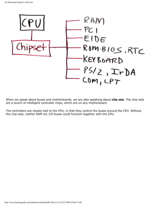
![An illustrated Guide to chip sets
Please click the banners to support our work!
KarbosGuide.com. Module 2d.01
On chip sets
Module 2d describes what chip sets are, and how they function on the motherboards. This module is
subdivided into the following pages:
1:
2:
3:
4:
5:
6:
7:
8:
What is a chip set?
The first chip sets for the Pentium boards
Non-Intel chip sets (mostly for Super 7 boards)
Chip sets for Intel P6 processors
More chip sets for Intel P6 processors
Intel's i810 "Whitney"
Intel's i820 "Camino"
Intel's i815 "Solano"
q Next page
q Previous
page
I recommend that you read all the pages one by one. Just follow the links "Next page" to get
through the textbook. I hope you find the information useful!
What is a chip set?
[top]
The chip set is very important to the modern PC and its performance. Many technologies meet on
the motherboard and are "glued" together via these controllers, which we call the "chip set".
http://www.karbosguide.com/hardware/module2d01.htm (1 of 5)7/27/2004 4:06:07 AM](https://image.slidesharecdn.com/computerrepair-acompleteillustratedguidetopchardware-140318001250-phpapp01/85/Computer-repair-_a_complete_illustrated_guide_to_pc_hardware-73-320.jpg)
![An illustrated Guide to chip sets
New technologies - new chip set [top]
Please support our
sponsor.
Therefore, the chip sets are quite central components on the motherboards. When new technological
features are introduced (and this happens continuously) they are often accompanied by new chip
sets. The new chip sets often enable:
q Higher speed on one or more buses
q Utilization of new facilities (new RAM types, new buses, improved EIDE, etc.)
The vendors
There are several suppliers of chip sets for the motherboard:
q Intel
q SIS
q Opti
q Via
q ALi
Intel has hitherto been the leader in supplying chip sets to the Pentium motherboard. Therefore, let
us just mention their chip sets, which have astronomical names.
The Neptune chip set (82434NX) was introduced in June 1994. It replaced the Mercury set
(82434LX). In both chip sets, there were problems with the PCI bus. In January 1995 Intel
introduced the first Triton, where everything worked. This chip set supports some new features: it
supports EDO RAM, and it offers bus master integrated EIDE control and NSP (Native Signal
Processing - one of the many new creations, which was soon forgotten).
However, the following chip sets were of much higher quality, and within very few years they lead to
several new generations of chip sets, each of them more powerful and offering great new features.
q Next page
q Previous page
Learn more [top]
If you want to read more about these and other chip sets, look for the excellent web site Toms
Hardware Guide. Here, you will find all about these subjects.
http://www.karbosguide.com/hardware/module2d01.htm (4 of 5)7/27/2004 4:06:07 AM](https://image.slidesharecdn.com/computerrepair-acompleteillustratedguidetopchardware-140318001250-phpapp01/85/Computer-repair-_a_complete_illustrated_guide_to_pc_hardware-76-320.jpg)
![An illustrated Guide to chip sets
Read more about RAM in module 2e
Read about the Pentium in module 3c
Read about the Pentium II's etc. in module 3e
[Main page] [Contact] [Karbo's Dictionary] [The Software Guides]
Copyright (c) 1996-2001 by Michael B. Karbo. KarbosGuide.com
http://www.karbosguide.com/hardware/module2d01.htm (5 of 5)7/27/2004 4:06:07 AM](https://image.slidesharecdn.com/computerrepair-acompleteillustratedguidetopchardware-140318001250-phpapp01/85/Computer-repair-_a_complete_illustrated_guide_to_pc_hardware-77-320.jpg)
![An illustrated Guide to chip sets
KarbosGuide.com. Module 2d.02
The first chip sets for the Pentium boards
The contents:
q Triton first and second
q A bridge to the I/O system
q USB and EIDE
q The differences between HX and VX
q The TX chip set
q Next page
q Previous page
Triton first and second [top]
The interest in chip sets and their performance started in late 1995, when the Pentium
processor became more popular. The Triton controllers were the first chip sets in this trend.
82430FX from late 1995 was Intel's next chip set and the first Triton. In February 1996 the
second generation of Triton arrived. Two new chip sets were introduced: The 82430VX and
82430HX. The last (HX) was the fastest one.
VX and HX
The two sets were similar, yet different. 430HX consisted of two chips. It was designed for
the more professional PCs. 430VX consisted of four chips, but the cost was slightly lower than
HX. It was aimed at the home use PC market. Let us look at the contents of each chip set:
http://www.karbosguide.com/hardware/module2d02.htm (1 of 7)7/27/2004 4:06:10 AM](https://image.slidesharecdn.com/computerrepair-acompleteillustratedguidetopchardware-140318001250-phpapp01/85/Computer-repair-_a_complete_illustrated_guide_to_pc_hardware-78-320.jpg)
![An illustrated Guide to chip sets
Chip set Contents
82430HX 82439HX System Controller (TXC)
+ 82371SB PCI ISA IDE Accelerator
82430VX 82437VX System Controller (TVX)
+ two 82438VX Data Path Units (TDX)
+ 82371SB PCI ISA IDE Accelerator
Common to both chip sets is 82371SB, which is a "PCI ISA IDE accelerator chip". It is also
called PIIX3, which some may recognize from the Windows 95 device driver, which comes
with the ASUS T2P4 board.
A bridge to the I/O system [top]
Please support our
sponsor.
The chip makes a bridge between the CPU, ISA and PCI bus. The news was, that it permitted
concurrent activity in all three locations, thus a new form of multitasking. This is significant
for daily use. All data exchange to and from I/O units cross this intersection, which now has
achieved greater width:
.
http://www.karbosguide.com/hardware/module2d02.htm (2 of 7)7/27/2004 4:06:10 AM](https://image.slidesharecdn.com/computerrepair-acompleteillustratedguidetopchardware-140318001250-phpapp01/85/Computer-repair-_a_complete_illustrated_guide_to_pc_hardware-79-320.jpg)
![An illustrated Guide to chip sets
US2 and EIDE
[top]
New in the chip was also the host function for USB. It is the Universal Serial Bus, which was
not much use at this time. Finally, the chip included a EIDE Bus Master control. In short that
means, that EIDE components like hard disks, to some extent can deliver their data directly
to RAM without taking up CPU time.
Above, you see the 82371SB chip and below, again, its placement relative to CPU and buses:
http://www.karbosguide.com/hardware/module2d02.htm (3 of 7)7/27/2004 4:06:10 AM](https://image.slidesharecdn.com/computerrepair-acompleteillustratedguidetopchardware-140318001250-phpapp01/85/Computer-repair-_a_complete_illustrated_guide_to_pc_hardware-80-320.jpg)
![An illustrated Guide to chip sets
Please click the banners to support our work!
The differences between HX and VX
[top]
It was generally accepted, that the HX set yielded the best performance of the two chip sets
described. But the VX set had two other facilities to offer: Capability for SMBA (Shared
Memory Buffer Architecture). That means among other things, that you can integrate the
http://www.karbosguide.com/hardware/module2d02.htm (4 of 7)7/27/2004 4:06:10 AM](https://image.slidesharecdn.com/computerrepair-acompleteillustratedguidetopchardware-140318001250-phpapp01/85/Computer-repair-_a_complete_illustrated_guide_to_pc_hardware-81-320.jpg)
![An illustrated Guide to chip sets
video card on the motherboard with 1 or 2 MB standard RAM, from the working RAM. A
technology, which is used only in the lowest cost PCs, and which soon was abandoned.
Also, the VX set also supported the fast RAM type SD-RAM. HX did not. The VX set could
control up to 128 MB RAM, but it could not cache above 64 MB RAM.
HX controlled 512 MB RAM and was the only Intel Pentium chip set to cache above 64 MB
RAM.
The VX and HX chip sets are both out. They were replaced by the TX chip set, which was the
last Intel chip set for Socket 7 mounted CPUs. Today Ali and VIA produces chip sets for
Socket 7 motherboards.
Intel TX chip set [top]
Please support our
sponsor.
The last chip set to Pentium processors were named 82430TX, which supports two new hot
technologies:
q SD-RAM
q Ultra DMA
Ultra DMA was also called ATA/33, and it is a standard for harddisk interface, which permits
EIDE hard disks to transfer at up to 33 MBps.
This improved EIDE standard is mostly marketed under the name Ultra DMA. Tests show that
Ultra DMA results in a speed increase of 25-75 percent over the traditional EIDE PIO mode 4.
Ultra DMA is the new EIDE standard and has been vastly enhanced since this chip set.
The controllers in the TX chip set
Chip set Chips included
82430TX 82439TX System Controller (TXC)
82371AB PCI ISA IDE Accelerator
The TX set is an update and improvement of the VX set. Relative to this, the TX firstly
http://www.karbosguide.com/hardware/module2d02.htm (5 of 7)7/27/2004 4:06:10 AM](https://image.slidesharecdn.com/computerrepair-acompleteillustratedguidetopchardware-140318001250-phpapp01/85/Computer-repair-_a_complete_illustrated_guide_to_pc_hardware-82-320.jpg)
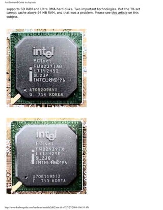
![An illustrated Guide to chip sets
Photos taken with Canon Powershot 600
The TX chip set was Intel's last and final set for Socket 7 motherboards. After that VIA and
ALi took over and continued this work.
q Next page
q Previous page
Learn more [top]
Read more about RAM in module 2e
Read about the Pentium in module 3c
Read about the Pentium II's etc. in module 3e
[Main page] [Contact] [Karbo's Dictionary] [The Software Guides]
Copyright (c) 1996-2001 by Michael B. Karbo. KarbosGuide.com
http://www.karbosguide.com/hardware/module2d02.htm (7 of 7)7/27/2004 4:06:10 AM](https://image.slidesharecdn.com/computerrepair-acompleteillustratedguidetopchardware-140318001250-phpapp01/85/Computer-repair-_a_complete_illustrated_guide_to_pc_hardware-84-320.jpg)

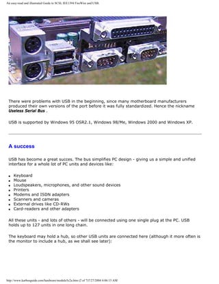
![An easy-read and illustrated Guide to SCSI, IEE1394 FireWire and USB.
Please click the banners to support our work!
KarbosGuide.com. Module 5c2a.
About USB
The contents:
q What is USB?
q After a slow start ..
On the following page:
q Next page: The USB hub
q Next module: IEEE1394 FireWire
q Device Bay
q Next page
q Previous page
What is USB? [top]
Please support our
sponsor.
USB stands for Universal Serial Bus. It is a cheap and rather slow I/O bus, running at 12 Mbit/
sec.
It can be compared to the FireWire bus, which however is a lot speedier.
USB is an open and royalty-free specification. Units can be plugged and unplugged on the fly
very easily. Here you see the plugs, the two small ones, number two from the left:
http://www.karbosguide.com/hardware/module5c2a.htm (1 of 7)7/27/2004 4:06:13 AM](https://image.slidesharecdn.com/computerrepair-acompleteillustratedguidetopchardware-140318001250-phpapp01/85/Computer-repair-_a_complete_illustrated_guide_to_pc_hardware-86-320.jpg)
![An easy-read and illustrated Guide to SCSI, IEE1394 FireWire and USB.
After a slow start ... [top]
Please support our
sponsor.
Personally I always believed, that USB a´´had to become a great renovation of the PC design.
However, things were moving very slowly in the beginning.
Bigger companies like Swiss Logitech (producing the best mice and trackballs available, at least
to my opinion) moved very slowly into USB. This probably has been due to serious concern
over the correct technical implementations. The COM, PS/2, and LPT ports represent very well-
known technology. Replacing them you have to be very certain of the consequences.
In 1999 and 2000 the USB products became available in large numbers. Many of them are
being sold both to Mac and PC. My latest trackball, a Kensington Orbit is only a Mac-product,
judging from the box:
http://www.karbosguide.com/hardware/module5c2a.htm (4 of 7)7/27/2004 4:06:13 AM](https://image.slidesharecdn.com/computerrepair-acompleteillustratedguidetopchardware-140318001250-phpapp01/85/Computer-repair-_a_complete_illustrated_guide_to_pc_hardware-89-320.jpg)
![An easy-read and illustrated Guide to SCSI, IEE1394 FireWire and USB.
However, the trackball (which is very fine) works fine on any PC with USB. The Windows USB
driver instantly recognizes the trackball.
The same goes for my great little tablet (Wacom Graphire):
Philips and Logitech - a private vision
[top]
If I were in charge, Philips should go further with USB. Already they build in a USB in their
monitors. Why not bundle the monitor with a cordless set of keyboard & mouse. And place the
infra-red receiver in the monitor using USB as interface? May I give this idea to Philips:
http://www.karbosguide.com/hardware/module5c2a.htm (5 of 7)7/27/2004 4:06:13 AM](https://image.slidesharecdn.com/computerrepair-acompleteillustratedguidetopchardware-140318001250-phpapp01/85/Computer-repair-_a_complete_illustrated_guide_to_pc_hardware-90-320.jpg)
![An easy-read and illustrated Guide to SCSI, IEE1394 FireWire and USB.
Philips even could buy Logitech as well. I think they would fit well together - two fine European
vendors.
Links
You find technical specifications etc. in these sites:
Intel's USB site http://www.intel.com/design/usb
USB site: http://www.usb.org
q Next page
q Previous page
Learn more [top]
Next module (on FireWire and Device Bay)
Read Module 6a about file systems
http://www.karbosguide.com/hardware/module5c2a.htm (6 of 7)7/27/2004 4:06:13 AM](https://image.slidesharecdn.com/computerrepair-acompleteillustratedguidetopchardware-140318001250-phpapp01/85/Computer-repair-_a_complete_illustrated_guide_to_pc_hardware-91-320.jpg)
![An easy-read and illustrated Guide to SCSI, IEE1394 FireWire and USB.
Read about chip sets on the motherboard in module 2d
Read Module 4d about super diskette and MO drives
Read module 5a about expansion cards, where we evaluate the I/O buses from the port side
Read module 5b about AGP
Read module 7a about monitors, and 7b on graphics card
Read module 7c about sound cards, and 7d on digital sound and music
[Main page] [Contact] [Karbo's Dictionary] [The Software Guides]
Copyright (c) 1996-2001 by Michael B. Karbo. www.karbosguide.com.
http://www.karbosguide.com/hardware/module5c2a.htm (7 of 7)7/27/2004 4:06:13 AM](https://image.slidesharecdn.com/computerrepair-acompleteillustratedguidetopchardware-140318001250-phpapp01/85/Computer-repair-_a_complete_illustrated_guide_to_pc_hardware-92-320.jpg)
![An easy-read and illustrated Guide to SCSI, IEE1394 FireWire and USB.
FireWire for Macintosh [top]
Please support our
sponsor.
FireWire was developed by Lucent Technologies, but has ended by Apple, who claims a $1 per
port royalty for use. IEEE1394 was conceived by Apple, who proposed it to IEEE, who
approved it as a standard in 1995. Firewire is Apple's implementation of the IEEE1394
standard. Other companies have implemented their own versions of IEEE1394. Yes, they are
not all the same! (Note: This is the purpose of the IEEE - to approve industry standards, not
to make an implementation.)
Hence all major hardware companies have adapted FireWire in some way. Especially the
entertainment electronic industry (Video/games/television) have great hopes with FireWire/
IEEE1394. It will connect all types of digital electronics with the PC and this way open up for
a much more modular design.
Since IEEE1394 is advanced and yet claimed to be cheap & simple, the communications
protocol can handle a lot of other units including:
http://www.karbosguide.com/hardware/module5c3.htm (3 of 6)7/27/2004 4:06:15 AM](https://image.slidesharecdn.com/computerrepair-acompleteillustratedguidetopchardware-140318001250-phpapp01/85/Computer-repair-_a_complete_illustrated_guide_to_pc_hardware-95-320.jpg)
![An easy-read and illustrated Guide to SCSI, IEE1394 FireWire and USB.
q Network controllers
q Hard disks, CDROM drives
q Printers
Two modes
The FireWire standard operates with two modes.
q Asynchronous as other buses. This means that operations across the bus are controlled
using interrupt signals. The bus reports to the host when a task is fulfilled.
q Iso-synchronous . In this mode data is being transferred at a steady preset speed -
continuously and without any supervision from the host. This opens up for data streaming
useful for video or the multimedia presentation. The FireWire is a peer-to-peer interface. This
means that data can be transferred between two units attached to the bus without
supervision from the PC.
FireWire has a 64 bit address bus. Compared to SCSI each unit does not need a unique ID,
they are dynamically configured "on the fly". Neither does the bus have to be terminated. All
together a lot simpler than SCSI.
One of the problems with SCSI has been the limitation on distance between the units.
FireWire can hold up to 16 units in the same "string" and there can be up to 4.5 meters
between two units.
The first implementations of FireWire will connect it to the PCI bus using the new PIX6-
controller, which will be a part of one of Intel's new chip sets. I think it will be at least 2-3
years before we really see this new technology in the market. But it will be worth waiting for
it, it opens up for a new world of inter connectivity between TV, PC, video and all other types
of electronic gear.
USB and FireWire - serial buses of the future
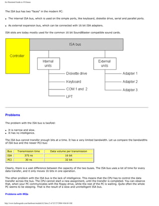
[top]
Soon high-end PC probably will hold both these serial I/O buses:
q USB version 2.0 for all low speed gear.
q FireWire for high speed I/O to Digital Video recorders, high-end scanners etc.
Both interfaces are about to be included in the south bridge of the chipsets. In 2002 it was
difficult to whether USB 2.0 or Firewire was going to be the new high-speed I/O standard.
Probably both of them will have place in the PC architecture the coming 1-2 years.
http://www.karbosguide.com/hardware/module5c3.htm (4 of 6)7/27/2004 4:06:15 AM](https://image.slidesharecdn.com/computerrepair-acompleteillustratedguidetopchardware-140318001250-phpapp01/85/Computer-repair-_a_complete_illustrated_guide_to_pc_hardware-96-320.jpg)
![An easy-read and illustrated Guide to SCSI, IEE1394 FireWire and USB.
Device Bay
[top]
DeviceBay is another standard which follows IEEE1394 and USB. These busses can connect
and disconnect units "on the fly", that is while the PC is operating. This ability to "hot plug"
requires a new physical connection between the units. DeviceBay may be the answer to this.
That is a standard for connection boxes that can hold hard disks, CDROM drives and similar
units.
The mounting frame can be installed without tools and while the PC is running. With this one
can imagine a storage unit filled with MP3 -files, which easily can be moved from a PC to the
player in the car. Unfortunately, for a while it is only a futuristic dream.
If DeviceBay really gains widespread usage, it could be the end of loose ribbon cables in the
PC cabinet. The whole PC can be made in modules, which all plug into the USB or the
FireWire bus as DeviceBay units. The units can then freely be moved between the different
computers and other electronic units in the home.
It is designed for hot plugging units like:
q Zip drives
q Tape streamers
q Modems
q Hard disks
q PC-card readers
These units will fit into a special bay connected to the USB and FireWire buses enabling the
hot plug. A good thought; however not all good thoughts end up in good hardware.
Links
You find technical specifications etc. in these sites:
Apple about: FireWire
The IEEE has its own page at http://www.ieee.org
About DeviceBay: www.device-bay.org
q Next page
q Previous page
http://www.karbosguide.com/hardware/module5c3.htm (5 of 6)7/27/2004 4:06:15 AM](https://image.slidesharecdn.com/computerrepair-acompleteillustratedguidetopchardware-140318001250-phpapp01/85/Computer-repair-_a_complete_illustrated_guide_to_pc_hardware-97-320.jpg)
![An easy-read and illustrated Guide to SCSI, IEE1394 FireWire and USB.
Learn more [top]
Read about chip sets on the motherboard in module 2d
Read Module 4d about super diskette and MO drives
Read module 5a about expansion cards, where we evaluate the I/O buses from the port side
Read module 5b about AGP
Read module 7a about monitors, and 7b on graphics card
Read module 7c about sound cards, and 7d on digital sound and music
[Main page] [Contact] [Karbo's Dictionary] [The Software Guides]
Copyright (c) 1996-2001 by Michael B. Karbo. www.karbosguide.com.
http://www.karbosguide.com/hardware/module5c3.htm (6 of 6)7/27/2004 4:06:15 AM](https://image.slidesharecdn.com/computerrepair-acompleteillustratedguidetopchardware-140318001250-phpapp01/85/Computer-repair-_a_complete_illustrated_guide_to_pc_hardware-98-320.jpg)
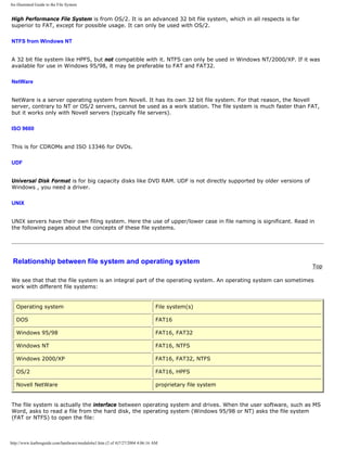
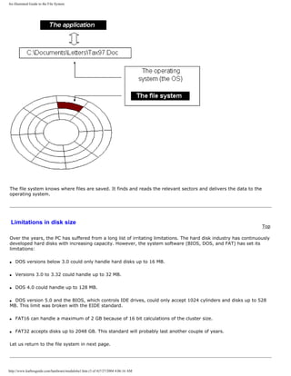
![An illustrated Guide to the File System
q Next page
q Previous page
Learn more Top
Read Windows tipswith a little about Windows 95/98.
Read Module 6c about the relationship between BIOS, OS and hardware
Read Module 7a about the videosystem
Read about video cards in Module 7b .
Read about digital sound in Module 7c .
[Main page] [Contact] [Karbo's Dictionary] [The Software Guides]
Copyright (c) 1996-2001 by Michael B. Karbo. www.karbosguide.com.
http://www.karbosguide.com/hardware/module6a1.htm (4 of 4)7/27/2004 4:06:16 AM](https://image.slidesharecdn.com/computerrepair-acompleteillustratedguidetopchardware-140318001250-phpapp01/85/Computer-repair-_a_complete_illustrated_guide_to_pc_hardware-102-320.jpg)
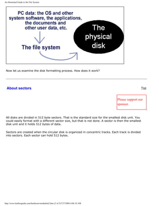
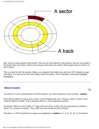
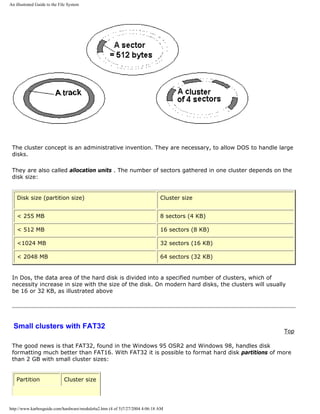
![An illustrated Guide to the File System
<8 GB 4 KB
8 GB - 16 GB 8 KB
16 GB - 32 GB 16 KB
> 32 GB 32 KB
Something else new in FAT32 is the moveable root directory, which can be of variable size. It
involves active use of both FATs (I cannot explain how). Altogether, it should make it simpler and
safer to change partition sizes. But the number of clusters per partition grows enormously in large
partitions.
FAT32 can only be installed in a new PC, since the partition has to be formatted in a special manner.
The file system is only available in the Windows 95 OSR2 (OEM Service Release 2) and in Windows
98.
q Next page
q Previous page
To learn more
Top
Read Module 6b with a little about Windows 95/98.
Read Module 6c about the relationship between BIOS, OS and hardware
Read Module 7a about the videosystem
Read about video cards in Module 7b .
Read about digital sound in Module 7c .
[Main page] [Contact] [Karbo's Dictionary] [The Software Guides]
http://www.karbosguide.com/hardware/module6a2.htm (5 of 5)7/27/2004 4:06:18 AM](https://image.slidesharecdn.com/computerrepair-acompleteillustratedguidetopchardware-140318001250-phpapp01/85/Computer-repair-_a_complete_illustrated_guide_to_pc_hardware-107-320.jpg)
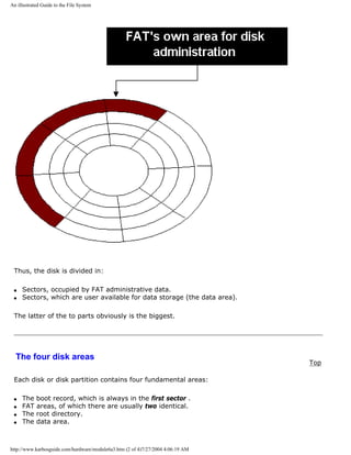
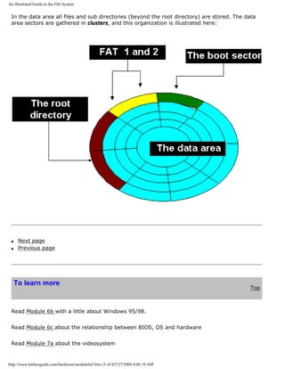
![An illustrated Guide to the File System
Read about video cards in Module 7b .
Read about digital sound in Module 7c .
[Main page] [Contact] [Karbo's Dictionary] [The Software Guides]
Copyright (c) 1996-2001 by Michael B. Karbo. www.karbosguide.com.
http://www.karbosguide.com/hardware/module6a3.htm (4 of 4)7/27/2004 4:06:19 AM](https://image.slidesharecdn.com/computerrepair-acompleteillustratedguidetopchardware-140318001250-phpapp01/85/Computer-repair-_a_complete_illustrated_guide_to_pc_hardware-111-320.jpg)
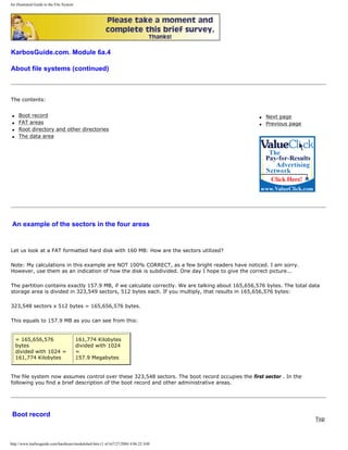
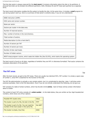
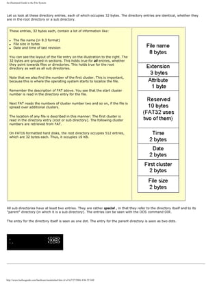
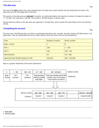
![An illustrated Guide to the File System
To learn more
Top
Read Module 6b with a little about Windows 95/98.
Read Module 6c about the relationship between BIOS, OS and hardware
Read Module 7a about the videosystem
Read about video cards in Module 7b .
Read about digital sound in Module 7c .
[Main page] [Contact] [Karbo's Dictionary] [The Software Guides]
Copyright (c) 1996-2001 by Michael B. Karbo. www.karbosguide.com.
http://www.karbosguide.com/hardware/module6a4.htm (6 of 6)7/27/2004 4:06:22 AM](https://image.slidesharecdn.com/computerrepair-acompleteillustratedguidetopchardware-140318001250-phpapp01/85/Computer-repair-_a_complete_illustrated_guide_to_pc_hardware-117-320.jpg)
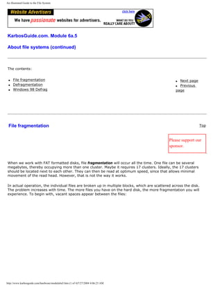
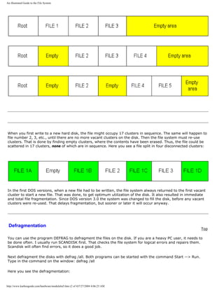
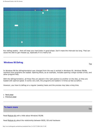
![An illustrated Guide to the File System
Read Module 7a about the videosystem
Read about video cards in Module 7b .
Read about digital sound in Module 7c .
[Main page] [Contact] [Karbo's Dictionary] [The Software Guides]
Copyright (c) 1996-2001 by Michael B. Karbo. www.karbosguide.com.
http://www.karbosguide.com/hardware/module6a5.htm (4 of 4)7/27/2004 4:06:23 AM](https://image.slidesharecdn.com/computerrepair-acompleteillustratedguidetopchardware-140318001250-phpapp01/85/Computer-repair-_a_complete_illustrated_guide_to_pc_hardware-121-320.jpg)
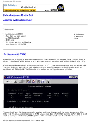
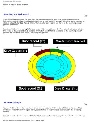
![An illustrated Guide to the File System
directories, each of which provides 32 bytes to the file name.
You should be happy about the long file names in Windows - it makes it much easier to identify saved files. The
only "danger" is, that you must not defragment the hard disk with a DOS based application. Then the long file
names are destroyed. The files still exist, but you can only find them under their 8.3 name and that is an
annoying experience, especially if you have thousands of files.
However, you should not waste memory and disk space using filenames 50 characters long. Usually filenames
of 15-20 characters work fine.
q Next page
q Previous page
To learn more
Top
Read Module 6b with a little about Windows 95/98.
Read Module 7a about the videosystem
Read about video cards in Module 7b .
Read about digital sound in Module 7c .
[Main page] [Contact] [Karbo's Dictionary] [The Software Guides]
Copyright (c) 1996-2001 by Michael B. Karbo. www.karbosguide.com.
http://www.karbosguide.com/hardware/module6a6.htm (6 of 6)7/27/2004 4:06:24 AM](https://image.slidesharecdn.com/computerrepair-acompleteillustratedguidetopchardware-140318001250-phpapp01/85/Computer-repair-_a_complete_illustrated_guide_to_pc_hardware-127-320.jpg)
![An illustrated guide to Operating Systems and the use ofhardware drivers
KarbosGuide.com. Module 6c1.
About operating systems and driver programs
The contents:
q What is an operating system?
q The operating system recognizes hardware
On the following pages:
q BIOS or driver programs
q Which operating systems?
q DOS control of hardware
q 32 bit drivers and installation
q Next page
q Previous page
Click & Learn deals primarily with hardware. In these pages I will cover the operating system
as it connects downward towards hardware. The operating system is closely associated with
the ROM BIOS program routines, which are described in module 2a . The two program layers
(operating system + BIOS) are called system software and it is very useful to understand
their importance for the PC.
Let us start by studying what an operating system really is.
What is an operating system? [top]
Please support our
sponsor.
Traditionally the operating system consists of three parts:
http://www.karbosguide.com/hardware/module6c1.htm (1 of 5)7/27/2004 4:06:26 AM](https://image.slidesharecdn.com/computerrepair-acompleteillustratedguidetopchardware-140318001250-phpapp01/85/Computer-repair-_a_complete_illustrated_guide_to_pc_hardware-129-320.jpg)
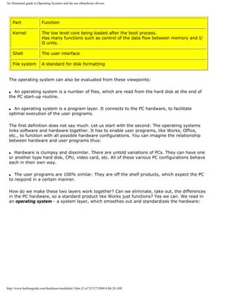
![An illustrated guide to Operating Systems and the use ofhardware drivers
You should understand the operating system as a necessary layer, which smoothes out
bumps and pot holes in your PC's hardware. This will give the user programs a stable, even
work platform.
The operating system recognizes hardware
[top]
The PC's hardware represents resources relative to the user program.
Think of your word processing program: You want to print your text. The program issues a
print order, expecting that the document will be printed as designed. The word processing
program dispatches data according to your commands. How they are translated to signals
understood by your printer - that is not the word processing program's problem. The printer
is a resource relative to the word processing program. The connections to these resources is
via the operating system. This holds true for all the resources, which are included in the PC
hardware:
http://www.karbosguide.com/hardware/module6c1.htm (3 of 5)7/27/2004 4:06:26 AM](https://image.slidesharecdn.com/computerrepair-acompleteillustratedguidetopchardware-140318001250-phpapp01/85/Computer-repair-_a_complete_illustrated_guide_to_pc_hardware-131-320.jpg)
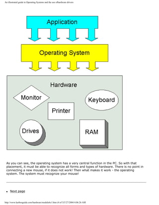
![An illustrated guide to Operating Systems and the use ofhardware drivers
q Previous page
Learn more [top]
Also see The Software Tips
Read of module 7a and module 7b about installation monitor and video card in Windows
95/98!
Read about chip sets on the motherboard in module 2d
Read module 5a about expansion cards, where we evaluate the I/O buses from the port side.
[Main page] [Contact] [Karbo's Dictionary] [The Software Guides]
Copyright (c) 1996-2001 by Michael B. Karbo. www.karbosguide.com.
http://www.karbosguide.com/hardware/module6c1.htm (5 of 5)7/27/2004 4:06:26 AM](https://image.slidesharecdn.com/computerrepair-acompleteillustratedguidetopchardware-140318001250-phpapp01/85/Computer-repair-_a_complete_illustrated_guide_to_pc_hardware-133-320.jpg)
![An illustrated guide to Operating Systems and the use ofhardware drivers
KarbosGuide.com. Module 6c2.
About OSs and drivers - continued
The contents:
q System software
q BIOS or driver programs
q Next page
q Previous page
System software
[top]
Together, the operating system and the ROM BIOS program routines form the layer on which
the user programs "rest." When the PC has to work, an operating system has to be read from
a disk. There are many different operating systems to choose from. However, the BIOS is
always placed firmly and centrally in the PC hardware.
BIOS - firmware
Please support our
sponsor.
One of the fundamental techniques in the PC design is the BIOS program layer. BIOS (Basic
Input Output System) is a group of small programs, furnished by the PC manufacturer - also
called firmware .
http://www.karbosguide.com/hardware/module6c2.htm (1 of 5)7/27/2004 4:06:28 AM](https://image.slidesharecdn.com/computerrepair-acompleteillustratedguidetopchardware-140318001250-phpapp01/85/Computer-repair-_a_complete_illustrated_guide_to_pc_hardware-134-320.jpg)
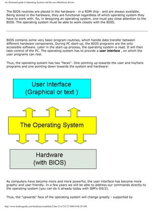
![An illustrated guide to Operating Systems and the use ofhardware drivers
technological development. The "downwards" face - the operating system's interface with
hardware - will change less. At least, the fundamental principles are the same as in the
childhood of the PC.
BIOS or drive programs
[top]
The operating system must be able to communicate with hardware. As we are going to see,
this can be done in two ways:
q The operating system communicates directly with hardware through drive programs.
q The operating system utilizes the BIOS programs.
While BIOS is hardware specific program code, stored in hardware, the drive programs are
small hardware specific program elements read from the disk together with the operating
system.
Depending on which operating system is installed, both principles are used in various
degrees. Since the BIOS programs consist of 16 bit code, it is typically DOS (a 16 bit
operating system) which utilizes BIOS to a large degree. In the newer 32 bit operating
systems, it is not efficient to use BIOS any more than necessary.
Here is a model, which shows the operating system with BIOS and drive programs (usually
just called drivers ):
http://www.karbosguide.com/hardware/module6c2.htm (3 of 5)7/27/2004 4:06:28 AM](https://image.slidesharecdn.com/computerrepair-acompleteillustratedguidetopchardware-140318001250-phpapp01/85/Computer-repair-_a_complete_illustrated_guide_to_pc_hardware-136-320.jpg)
![An illustrated guide to Operating Systems and the use ofhardware drivers
As you can see, the driver/BIOS functions are closely associated with the operating system.
So let us look at that on the following page.
q Next page
q Previous page
Learn more [top]
Also see The Software Tips
Read of module 7a and module 7b about installation monitor and video card in Windows
95/98!
http://www.karbosguide.com/hardware/module6c2.htm (4 of 5)7/27/2004 4:06:28 AM](https://image.slidesharecdn.com/computerrepair-acompleteillustratedguidetopchardware-140318001250-phpapp01/85/Computer-repair-_a_complete_illustrated_guide_to_pc_hardware-137-320.jpg)
![An illustrated guide to Operating Systems and the use ofhardware drivers
Read about chip sets on the motherboard in module 2d
Read module 5a about expansion cards, where we evaluate the I/O buses from the port side.
[Main page] [Contact] [Karbo's Dictionary] [The Software Guides]
Copyright (c) 1996-2001 by Michael B. Karbo. www.karbosguide.com.
http://www.karbosguide.com/hardware/module6c2.htm (5 of 5)7/27/2004 4:06:28 AM](https://image.slidesharecdn.com/computerrepair-acompleteillustratedguidetopchardware-140318001250-phpapp01/85/Computer-repair-_a_complete_illustrated_guide_to_pc_hardware-138-320.jpg)
![An illustrated guide to Operating Systems and the use ofhardware drivers
KarbosGuide.com. Module 6c3.
About OSs and drivers - continued
The contents:
q Which operating systems?
q DOS control of hardware
q Next page
q Previous page
Which operating systems?
[top]
The operating systems have undergone a tremendous development since 1981. It all started with DOS, which
was a 16 bit modification of a simple 8 bit operating system called CP/M.
DOS was further developed in the 1980s. Since around 1990 Windows came into the scene. Windows started as a
GUI ( Graphic User Interface ) for DOS.
The PC booted with DOS as operating system. Then you could choose, if you wanted mouse and graphics on the
screen with Windows . Windows was a supplement to DOS.
The Graphic User Interface (GUI) allows you to work with a mouse instead of writing long command lines like
copy c:texts*.* d:textbak *.* /s/v/, which is the standard in text based operating systems (like DOS).
DOS was designed for 16 bit computers, which the first PCs were. With Intel's 80386 the 32 bit technology was
knocking at the door. Modern PCs are designed for straight 32 bit program execution. So we have seen a gradual
trend in the PC operating systems from 16 bit towards 32 bit and this affects hardware design.
http://www.karbosguide.com/hardware/module6c3.htm (1 of 5)7/27/2004 4:06:30 AM](https://image.slidesharecdn.com/computerrepair-acompleteillustratedguidetopchardware-140318001250-phpapp01/85/Computer-repair-_a_complete_illustrated_guide_to_pc_hardware-139-320.jpg)
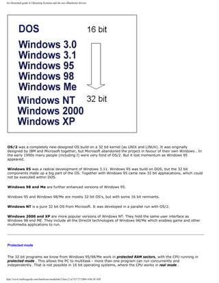
![An illustrated guide to Operating Systems and the use ofhardware drivers
A brief comparison of 16 bit and 32 bit operating systems can look like this:
Operating system DOS 32 bit operating system (NT, OS/2, UNIX)
Users Single user Multiple users
Program execution 16 bit single task in real mode 32 bit multitask in protected mode
Screen appearance Mostly Text based (poor quality
graphics)
Often GUI - graphic interface with high
resolution graphics
Hardware handling Primarily BIOS Custom designed 32 bit drivers for each
hardware component.
DOS control of hardware [top]
Please support our
sponsor.
DOS is quite simple to describe, since it principally consists of only 4 parts:
q A boot record, which activates the operating system.
q The file IO.SYS, which is interfaced to ROM BIOS with installation of device drivers .
q The file MSDOS.SYS. That is the core of DOS, handling the file system and program execution.
q The file COMMAND.COM, which provides the command line, the text based user interface.
When we talk about hardware control, it is done through IO.SYS. That is a program which reads the ROM BIOS
code and converts it to DOS's own device drivers.
The smart thing about DOS is that the operating system can be expanded with external device drivers. IO.SYS
reads them via the start-up file CONFIG.SYS. First device drivers are read from ROM BIOS. Then any possible
additional drivers are read from disk. In that way DOS can handle hardware units which did not exist when the
PC was originally configured.
A final option to handle hardware from DOS programs is to write special drivers for the individual user program .
Many DOS games come with their own graphics drivers (they have to recognize all graphics standards on the
market!). Another classic example is the word processing program WordPerfect, which in its prime (version 5.1)
came with drivers to more than 500 different printers!
Unit Example of DOS device drivers
Hard disk BIOS
Video card BIOS
Mouse MOUSE.SYS
http://www.karbosguide.com/hardware/module6c3.htm (3 of 5)7/27/2004 4:06:30 AM](https://image.slidesharecdn.com/computerrepair-acompleteillustratedguidetopchardware-140318001250-phpapp01/85/Computer-repair-_a_complete_illustrated_guide_to_pc_hardware-141-320.jpg)
![An illustrated guide to Operating Systems and the use ofhardware drivers
CD-ROM ATAPI.SYS + MSCDEX.EXE
Printer Internal drivers in the user program (like WordPerfect 5.1)
The device drivers can be seen with the program MSD. Here is a picture from Windows 95, where you can clearly
see the names of the device drivers (CON, PRN, LPT1 etc.):
All these device drivers are in 16 bit program code.
q Next page
q Previous page
Learn more [top]
Also see The Software Tips
Read of module 7a and module 7b about installation monitor and video card in Windows 95/98!
http://www.karbosguide.com/hardware/module6c3.htm (4 of 5)7/27/2004 4:06:30 AM](https://image.slidesharecdn.com/computerrepair-acompleteillustratedguidetopchardware-140318001250-phpapp01/85/Computer-repair-_a_complete_illustrated_guide_to_pc_hardware-142-320.jpg)
![An illustrated guide to Operating Systems and the use ofhardware drivers
Read about chip sets on the motherboard in module 2d
Read module 5a about expansion cards, where we evaluate the I/O buses from the port side.
[Main page] [Contact] [Karbo's Dictionary] [The Software Guides]
Copyright (c) 1996-2001 by Michael B. Karbo. www.karbosguide.com.
http://www.karbosguide.com/hardware/module6c3.htm (5 of 5)7/27/2004 4:06:30 AM](https://image.slidesharecdn.com/computerrepair-acompleteillustratedguidetopchardware-140318001250-phpapp01/85/Computer-repair-_a_complete_illustrated_guide_to_pc_hardware-143-320.jpg)
![An illustrated guide to Operating Systems and the use ofhardware drivers
Please click the banners to support our work!
KarbosGuide.com. Module 6c4.
About OSs and drivers - continued
The contents:
q 32 bit drivers
q Installation of new drivers
q Next page
q Previous page
32 bit drivers
[top]
In 32 bit operating systems, you use 32 bit drivers instead of ROM BIOS. This means that software suppliers like Microsoft and IBM must be able to supply drivers
to all conceivable hardware. The advantage is, that once the operating system has installed drivers, all user programs operate alike relative to hardware.
It is an enormous project to supply drivers. Especially OS/2 has suffered problems in getting the right drivers on the market. For many years, IBM for example did
not supply OS/2 drivers for Canon printers. That was part of my reason to drop that operating system. Regarding driver installations, Windows 98 is
unquestionably the best operating system.
Windows supports plug and play. The operating system searches the PC for hardware. Often all drivers (to CD-ROM, network controller, sound card, etc.) are
installed automatically. The drivers can be seen under System in the control panel.
Let us look at a EIDE hard disk. The hard disk operation is regulated by an EIDE controller on the system board. Therefore, Windows must have a driver installed
to this controller. We can find it easily. Go to: My computer -> Control panel -> System -> Computer. In Windows 2000 you should click on Device manager:
http://www.karbosguide.com/hardware/module6c4.htm (1 of 6)7/27/2004 4:06:33 AM](https://image.slidesharecdn.com/computerrepair-acompleteillustratedguidetopchardware-140318001250-phpapp01/85/Computer-repair-_a_complete_illustrated_guide_to_pc_hardware-144-320.jpg)
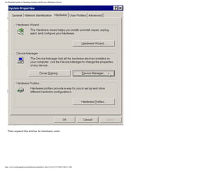
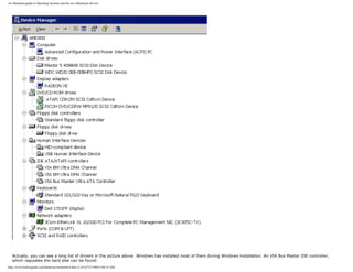
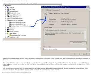
![An illustrated guide to Operating Systems and the use ofhardware drivers
Installation of new drivers [top]
Please support our
sponsor.
You install new drivers in Windows 98/Me/2000 with "add new hardware" found in My Computer -> Control panel:.
http://www.karbosguide.com/hardware/module6c4.htm (5 of 6)7/27/2004 4:06:33 AM](https://image.slidesharecdn.com/computerrepair-acompleteillustratedguidetopchardware-140318001250-phpapp01/85/Computer-repair-_a_complete_illustrated_guide_to_pc_hardware-148-320.jpg)
![An illustrated guide to Operating Systems and the use ofhardware drivers
Don't let Windows search for hardware. Instead choose yourself. Then you have to select the particular hardware from the list and in the next screen click "Have
diskette... " Learn this technique if you experiment with your PC and want maximal benefits from your hardware.
q Next page
q Previous page
Learn more [top]
Also see The Windows 98 page (module 6d)
Read of module 7a and module 7b about installation monitor and video card in Windows 95/98!
Read about chip sets on the motherboard in module 2d
Read module 5a about expansion cards, where we evaluate the I/O buses from the port side.
[Main page] [Contact] [Karbo's Dictionary] [The Software Guides]
http://www.karbosguide.com/hardware/module6c4.htm (6 of 6)7/27/2004 4:06:33 AM](https://image.slidesharecdn.com/computerrepair-acompleteillustratedguidetopchardware-140318001250-phpapp01/85/Computer-repair-_a_complete_illustrated_guide_to_pc_hardware-149-320.jpg)
![An illustrated Guide to Monitors and the Video System
Please click the banners to support our work!
KarbosGuide.com. Module 7
q About the video system
q About video cards
q About sound cards
q About digital sound and music.
The contents on this and following pages:
q Introduction
q Concepts and terminology
q Screen resolution, screen size etc.
q About colors, color depth, RGB etc.
q About refresh rates
q TCO standards
q LCD displays
The video system (of which the monitor is a part) is one of the most
important components in the PC. It affects directly your pleasure of working,
and actually also your health. At the same time, the video system shows the
biggest variation between different PCs. Read my coverage of this subject
here in this module, which is subdivided into several pages.
q Next page
q Previous page
Introduction
[top]
All computers are connected to some type of display, which usually is called the monitor. Monitors are
available in many different types and sizes. The size generally goes from 12 to 21 inches diagonal.
The monitor is a part of the computer video system. To understand how to obtain a good screen image,
we need to look at the complete video system. It includes these three elements:
q The graphics card (also called the video card or video adapter). It is an expansion card, which
generates electric signals to the monitor.
q The monitor itself, which is connected by a cable to the video card using some kind of interface.
q A device driver which Windows uses to control the video card, to make it send the correct signals to
the monitor.
http://www.karbosguide.com/hardware/module7a1.htm (1 of 3)7/27/2004 4:06:35 AM](https://image.slidesharecdn.com/computerrepair-acompleteillustratedguidetopchardware-140318001250-phpapp01/85/Computer-repair-_a_complete_illustrated_guide_to_pc_hardware-150-320.jpg)
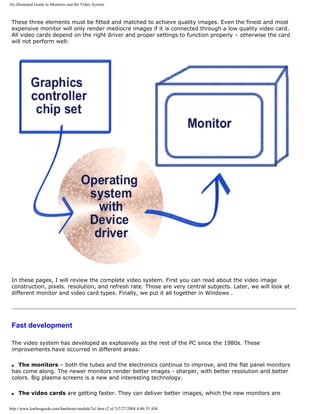
![An illustrated Guide to Monitors and the Video System
capable of producing. The user gets more tuning options. New RAM types and buses will increase speed,
and new features are added.
q Video presentation, DVD, and 3D games are other areas of development, which will change the
video card standards.
The video system is a sub system in the PC, with its own technological development. At the same time,
monitors and video cards are areas, where manufacturers and dealers often cut corners. As an ordinary
user, you can improve your screen images significantly with careful planning. That holds true when you
buy your PC - you must select your video system carefully.
It also holds true for existing video systems, where better drivers and software optimizing can help
produce the optimal screen image. We will look at that in these pages.
q Next page
q Previous page
Learn more Top
Read about video cards in Module 7b .
Read about sound cards in Module 7c .
Read about digital sound and music in Module 7d .
[Main page] [Contact] [Karbo's Dictionary] [The Software Guides]
Copyright (c) 1996-2001 by Michael B. Karbo. www.karbosguide.com.
http://www.karbosguide.com/hardware/module7a1.htm (3 of 3)7/27/2004 4:06:35 AM](https://image.slidesharecdn.com/computerrepair-acompleteillustratedguidetopchardware-140318001250-phpapp01/85/Computer-repair-_a_complete_illustrated_guide_to_pc_hardware-152-320.jpg)
![An illustrated Guide to the Video Cards
which also had limited power.
q Next page
q Previous page
To learn more
Top
Read about monitors in Module 7a.
Read about sound cards in Module 7c .
Read about digital sound and music in Module 7d .
Read about FPU work in 3D graphics.
[Main page] [Contact] [Karbo's Dictionary] [The Software Guides]
Copyright (c) 1996-2001 by Michael B. Karbo. www.karbosguide.com.
http://www.karbosguide.com/hardware/module7b1.htm (5 of 5)7/27/2004 4:06:37 AM](https://image.slidesharecdn.com/computerrepair-acompleteillustratedguidetopchardware-140318001250-phpapp01/85/Computer-repair-_a_complete_illustrated_guide_to_pc_hardware-157-320.jpg)
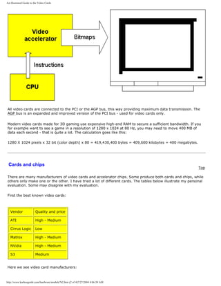
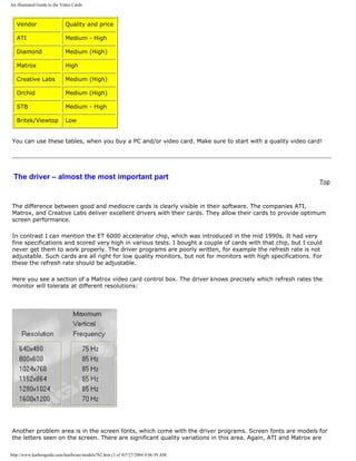
![An illustrated Guide to the Video Cards
worth mentioning.
q Next page
q Previous page
To learn more
Top
Read about video basics in Module 7a.
Read about sound cards in Module 7c .
Read about digital sound and music in Module 7d .
Read about FPU work in 3D graphics.
[Main page] [Contact] [Karbo's Dictionary] [The Software Guides]
Copyright (c) 1996-2001 by Michael B. Karbo. www.karbosguide.com.
http://www.karbosguide.com/hardware/module7b2.htm (4 of 4)7/27/2004 4:06:39 AM](https://image.slidesharecdn.com/computerrepair-acompleteillustratedguidetopchardware-140318001250-phpapp01/85/Computer-repair-_a_complete_illustrated_guide_to_pc_hardware-161-320.jpg)
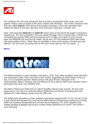
![An illustrated Guide to the Video Cards
could be a Mag or ViewSonic. Both make excellent Trinitron screens at reasonable prices.
Combine the monitor with an ATI or maybe Matrox video card and you will have a good video
system!
However, to make a good and lasting purchase, you have to understand your own video
demands. Do you need:
q Office programs with 2D graphics?
q 3D games?
q DVD acceleration?
q DVI interface?
You should get a demonstration of the card and monitor you want to buy. Especially if it is in
the low/medium price group, I will strongly recommend that you see it connected. Then
evaluate the screen image. How sharp is it? Does it flicker? Ask about resolution, color depth
and refresh rate. If the dealer cannot answer these questions, I would not trust him. Finally,
find out which driver the card needs. Read on...
q Next page
q Previous page
To learn more
Top
Read about video basics in Module 7a
Read about sound cards in Module 7c
Read about digital sound and music in Module 7d
Read about FPU work in 3D graphics
[Main page] [Contact] [Karbo's Dictionary] [The Software Guides]
Copyright (c) 1996-2001 by Michael B. Karbo. www.karbosguide.com.
http://www.karbosguide.com/hardware/module7b3.htm (5 of 5)7/27/2004 4:06:41 AM](https://image.slidesharecdn.com/computerrepair-acompleteillustratedguidetopchardware-140318001250-phpapp01/85/Computer-repair-_a_complete_illustrated_guide_to_pc_hardware-166-320.jpg)
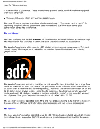
![An illustrated Guide to the Video Cards
SiS540 for AMD K6-III. These sets hold 2D/3D graphics engines as well as a lot of other
features - all in just one chip.
q On April 11, 2000 the company S3 announced that they had agreed to transfer its PC
graphics chip business to the successfull Taiwanese chip set producer VIA
q ATI's has also announced, that they are devoloping full chip sets integrated with their own
graphics controllers. We have not seen them. ATI and Matrox seems to survive in the market
by delivering high-end graphic chip sets without getting involved with the motherboard
manufactures. NVidia lives them same way serving the market for game PCs.
q Next page
q Previous page
To learn more
Top
Read about video basics in Module 7a
Read about sound cards in Module 7c
Read about digital sound and music in Module 7d
Read about FPU work in 3D graphics
[Main page] [Contact] [Karbo's Dictionary] [The Software Guides]
Copyright (c) 1996-2001 by Michael B. Karbo. www.karbosguide.com.
http://www.karbosguide.com/hardware/module7b4.htm (6 of 6)7/27/2004 4:06:49 AM](https://image.slidesharecdn.com/computerrepair-acompleteillustratedguidetopchardware-140318001250-phpapp01/85/Computer-repair-_a_complete_illustrated_guide_to_pc_hardware-172-320.jpg)
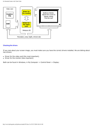
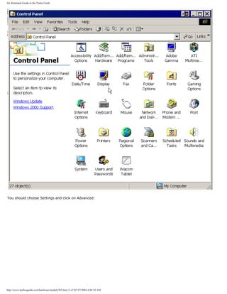
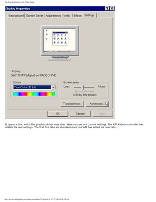
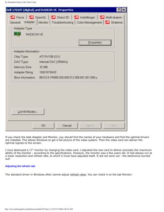
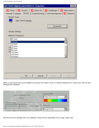
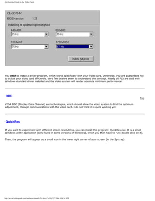
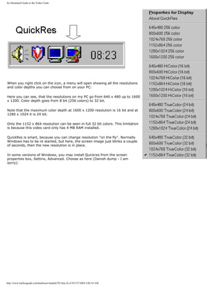
![An illustrated Guide to the Video Cards
After clicking OK the little icon is in the Systray.
q Next page
q Previous page
To learn more
Top
Read about video basics in Module 7a.
Read about digital sound and music in Module 7d .
Read about FPU work in 3D graphics.
[Main page] [Contact] [Karbo's Dictionary] [The Software Guides]
Copyright (c) 1996-2001 by Michael B. Karbo. www.karbosguide.com.
http://www.karbosguide.com/hardware/module7b5.htm (9 of 9)7/27/2004 4:06:54 AM](https://image.slidesharecdn.com/computerrepair-acompleteillustratedguidetopchardware-140318001250-phpapp01/85/Computer-repair-_a_complete_illustrated_guide_to_pc_hardware-181-320.jpg)
![A guide to sound cards and digital sound
Please click the banners to support our work!
KarbosGuide.com. Module 7c1.
PC sound
The contents:
q An introduction
q The synthesizer
q The A/D conversion
q Sampling the Wav files
q Next page
q Previous page
I do not claim to be an expert in sound cards. But I will try to describe what little I know about this
technology. The sound capabilities of the PC are quite interesting. In the late 1990s, new and radical
designs in sound technology appeared, and at the same time the MP3 wave swept the Internet society.
On the first pages we shall describe the traditional sound card concept (the Sound Blaster compatible
sound card). Then follows something on the newer technologies.
Introduction
[top]
Sound cards have a minimum of four tasks. They function as:
q Synthesizer
q MIDI interface
q Analog-to-digital conversion during the recording (A/D).
q Digital-to-analog conversion during the playback (D/A). All elements are to be explained on these
pages, so please read on.
The synthesizer
http://www.karbosguide.com/hardware/module7c1.htm (1 of 6)7/27/2004 4:06:57 AM](https://image.slidesharecdn.com/computerrepair-acompleteillustratedguidetopchardware-140318001250-phpapp01/85/Computer-repair-_a_complete_illustrated_guide_to_pc_hardware-182-320.jpg)
![A guide to sound cards and digital sound
The synthesizer delivers the sound. That is, the sound card generates the sounds. Here we have three
systems:
q FM synthesis, Frequency Modulation
q Wave table
q Physical modeling
FM synthesis
The cheapest sounds card use the FM technology to generate sounds simulating various instruments.
Those are true synthesizers. The sounds are synthetic – it may sound like a piano, but it is not. FM
synthesis is and sounds like the artificial sounds it consists of.
Wave tables - sampling
Wave table is the best and most expensive sound technology. This means that the sounds on the sound
card are recorded from real instruments. You record, for example, from a real piano and make a small
sample based on the recording. This sample is stored on the sound card.
When the music has to be played, you are actually listening to these samples. When they are of good
quality, the sound card can produce very impressive sounds, where the "piano" sounds like a piano.
Wave table is used in Sound Blaster's AWE card.
Physical modeling
Physical modeling synthesis is a third sound producing technology. It involves simulating sounds
through programming. The process is supposed to be rather cumbersome, but it should yield a number
of other advantages. The original Sound Blaster Gold card contains 14 instrument sounds, which are
created from physical models.
Testing the sound
The basic quality of a sound card can be tested by playing a MIDI file. Then you can easily hear the
difference. There is also a difference in how many notes (polyphony) can be played simultaneously. If
you want to compose your own music on your PC, you use the sounds available on your sound card. The
greater works you want to write, the more "voices" you will need. The SB AWE64 card has 64 voices,
while SB16 only has 20 voices.
Some sound cards can import new sounds. They are simply downloaded to the sound card, which might
have 512 KB (Sound Blaster AWE64) or 4 MB RAM (Sound Blaster AWE64 Gold) available for the user's
own sounds.
The A/D conversion
[top]
You need a A/D conversion, when analog sound signals are recorded, i.e. from a microphone. The other
way around, the D/A-converter is used when the digital sounds have to be reproduced into a signal for
the speakers amplifier.
http://www.karbosguide.com/hardware/module7c1.htm (2 of 6)7/27/2004 4:06:57 AM](https://image.slidesharecdn.com/computerrepair-acompleteillustratedguidetopchardware-140318001250-phpapp01/85/Computer-repair-_a_complete_illustrated_guide_to_pc_hardware-183-320.jpg)
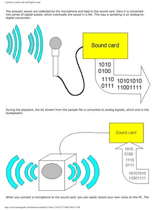
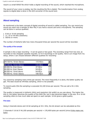
![A guide to sound cards and digital sound
This gives us the following file sizes of sampled stereo music in CD quality:
Replay Number of
bytes
One minute 10 MB
One hour 605 MB
74 Minutes 746 MB
Here you see the settings in a Wave program:
Stereo sampling at 16 bit and 44 KHz gives the best quality, but the Wave files will take up quite a bit
more space.
The Wav files
[top]
If you look down in your PC, you will find plenty of Wav files. I did a little search, and this showed up:
http://www.karbosguide.com/hardware/module7c1.htm (5 of 6)7/27/2004 4:06:57 AM](https://image.slidesharecdn.com/computerrepair-acompleteillustratedguidetopchardware-140318001250-phpapp01/85/Computer-repair-_a_complete_illustrated_guide_to_pc_hardware-186-320.jpg)
![A guide to sound cards and digital sound
All these Wav files contain sounds in a digital form - samples. They only contain very few seconds of
sound, because of the file size, which must not grow too big.
A Wav file will sound the same no matter which sound card you may have, be it a sound card using FM
Synthesis or Wave table. The sound is in the file and not in the sound card!
These samples above are used as sound effects within Windows. Similar samples are used as material
on music CDs and in the MOD format of digital music.
AU is another file format for samples. MP3 files are highly compressed samples.
q Next page
q Previous page
Learn more [top]
Also see: Module 7d - about digital music: MP3s, MODs etc.
Read about video cards in Module 7b .
[Main page] [Contact] [Karbo's Dictionary] [The Software Guides]
Copyright (c) 1996-2001 by Michael B. Karbo. www.karbosguide.com.
http://www.karbosguide.com/hardware/module7c1.htm (6 of 6)7/27/2004 4:06:57 AM](https://image.slidesharecdn.com/computerrepair-acompleteillustratedguidetopchardware-140318001250-phpapp01/85/Computer-repair-_a_complete_illustrated_guide_to_pc_hardware-187-320.jpg)
![A guide to sound cards and digital sound
Please click the banners to support our work!
KarbosGuide.com. Module 7c2.
PC sound - continued
The contents:
q The sound card - an adapter
q Newer sound cards
q Next page
q Previous page
The sound card - an adapter
[top]
In the previous module, we saw the principles of PC sound. Let us here look at the sound card, which is an
adapter card.
The sound card used to be a ISA card (using the old ISA interface). Here you see the original Sound Blaster
AWE64 Gold card:
http://www.karbosguide.com/hardware/module7c2.htm (1 of 4)7/27/2004 4:06:59 AM](https://image.slidesharecdn.com/computerrepair-acompleteillustratedguidetopchardware-140318001250-phpapp01/85/Computer-repair-_a_complete_illustrated_guide_to_pc_hardware-188-320.jpg)
![A guide to sound cards and digital sound
The connectors may look different on different sound cards, but as an example: In the back of the AWE64 Gold
card you find connectors to:
q Microphone input, a jack
q Line input, a jack
q Two phone jacks for active speakers
q A DB15 jack for MIDI or joystick.
Most sound cards typically have a 2 Watt amplifier built-in. It can push a set of earphones. An exception is the
SB Gold card, where the amplifier is eliminated. It has no practical significance, since you probably want to
attach it to a pair of active speakers.
The new sound cards
[top]
For many years PC sound has been totally dominated by the Sound Blaster card. All sound cards had to be
compatible with Sound Blaster, or it would not sell. Obviously that is due to the numerous game programs,
which require a SB compatible sound card.
The new sound cards break away from the Sound Blaster compatbility. This break involves many facets. Below
I will describe some of the tendencies in the sound technology.
Sound over the PCI bus
New sound cards use the PCI bus. The SB compatibility used to require the old ISA bus, but this has been
overcome. Creative Labs produce fine PCI-based SoundBlaster cards. With PCI you gain these advantages:
q The IRQ problems disappear.
q Signal/noise ratio can be improved with 5 dB.
q There is sufficient bandwidth (capacity for data transmission).
http://www.karbosguide.com/hardware/module7c2.htm (2 of 4)7/27/2004 4:06:59 AM](https://image.slidesharecdn.com/computerrepair-acompleteillustratedguidetopchardware-140318001250-phpapp01/85/Computer-repair-_a_complete_illustrated_guide_to_pc_hardware-189-320.jpg)
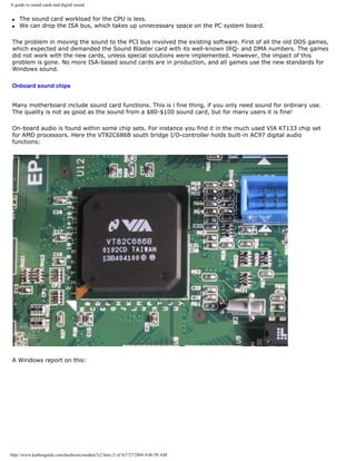
![A guide to sound cards and digital sound
Onboard sound chips is an in-expensive an simple via to incorporate sound facilities in your PC.
q Next page
q Previous page
Learn more [top]
Read Module 6a about file systems
Read about chip sets on the motherboard in module 2d
Read Module 4d about super diskette and MO drives
Read module 5a about expansion cards, where we evaluate the I/O buses from the port side
Read module 5b about AGP
Read module 7a about monitors, and 7b on graphics card
Also see: Module 7d - about digital music: MP3s, MODs etc.
[Main page] [Contact] [Karbo's Dictionary] [The Software Guides]
Copyright (c) 1996-2001 by Michael B. Karbo. www.karbosguide.com.
http://www.karbosguide.com/hardware/module7c2.htm (4 of 4)7/27/2004 4:06:59 AM](https://image.slidesharecdn.com/computerrepair-acompleteillustratedguidetopchardware-140318001250-phpapp01/85/Computer-repair-_a_complete_illustrated_guide_to_pc_hardware-191-320.jpg)
![A guide to sound cards and digital sound
Please click the banners to support our work!
KarbosGuide.com. Module 7c3.
PC sound - continued
The contents:
q 3D sound q Next page
q Previous page
3D sound
[top]
3D sound is a new hot area. You can create a very powerful illusion of 3D sound coming from just
loudspeaker. This is done using new 3D processors on the sound card, which work with some very
complex mathematical models. The sound comes from behind, from the front, from side to side -
completely realistic.
The idea of 3D sound has to come from games, which especially are designed for it. The sound systems
often include 4 or 6 loudspeakers. But they work fine with headphones too.
Sound Blaster Live is such a high-end, high fidelity 3D card coming from Creative Labs. It is a PCI-based
card, and the best performance comes with the Four Point Surround sound system. Diamond MX300 is
another.
SB Live!
The SoundBlaster top model sound card is called SoundBlaster Live!
It includes a lot of fine and powerful features:
q EMU10K1 accelerator chip
http://www.karbosguide.com/hardware/module7c3.htm (1 of 4)7/27/2004 4:07:01 AM](https://image.slidesharecdn.com/computerrepair-acompleteillustratedguidetopchardware-140318001250-phpapp01/85/Computer-repair-_a_complete_illustrated_guide_to_pc_hardware-192-320.jpg)
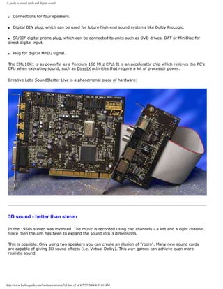
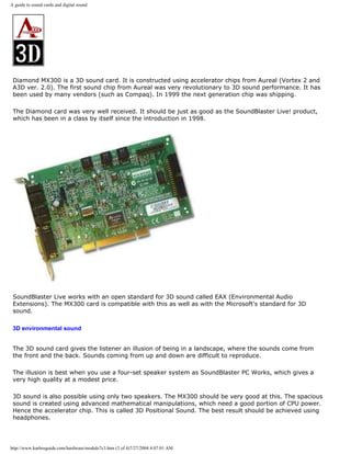
![A guide to sound cards and digital sound
Another 3D effect is called Environmental Sound. Here the sound from a game is changed corresponding
to the physical situation of the characters. If a person enters a tunnel, there may be an echo. In a big
empty hall the sound is completely different. This way the games can send commands to the sound
card, which adjust the feeling of the sound to the environment.
q Next page
q Previous page
Learn more
[top]
Read Module 6a about file systems
Read about chip sets on the motherboard in module 2d
Read Module 4d about super diskette and MO drives
Read module 5a about expansion cards, where we evaluate the I/O buses from the port side
Read module 5b about AGP
Read module 7a about monitors, and 7b on graphics card
Also see: Module 7d - about digital music: MP3s, MODs etc.
[Main page] [Contact] [Karbo's Dictionary] [The Software Guides]
Copyright (c) 1996-2001 by Michael B. Karbo. www.karbosguide.com.
http://www.karbosguide.com/hardware/module7c3.htm (4 of 4)7/27/2004 4:07:01 AM](https://image.slidesharecdn.com/computerrepair-acompleteillustratedguidetopchardware-140318001250-phpapp01/85/Computer-repair-_a_complete_illustrated_guide_to_pc_hardware-195-320.jpg)
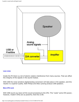
![A guide to sound cards and digital sound
You find high fidelity loudspeakers with built-in amplifier and converter, which can receive
pure digital signals (via USB). One could hope, that these speakers will be able to interpret
data from hi-fi equipment, PC, TV/video and other sources. See the description of some of
the finest speakers I ever have heard: A set ofPhilips USB speakers.
q Next page
q Previous page
Learn more [top]
Also see: Module 7d - about digital music: MP3s, MODs etc.
[Main page] [Contact] [Karbo's Dictionary] [The Software Guides]
Copyright (c) 1996-2001 by Michael B. Karbo. www.karbosguide.com.
http://www.karbosguide.com/hardware/module7c4.htm (3 of 3)7/27/2004 4:07:03 AM](https://image.slidesharecdn.com/computerrepair-acompleteillustratedguidetopchardware-140318001250-phpapp01/85/Computer-repair-_a_complete_illustrated_guide_to_pc_hardware-198-320.jpg)
![A guide to sound cards and digital sound
Please click the banners to support our work!
KarbosGuide.com. Module 7c5.
PC sound - continued
The contents:
q DOS or DirectX q Next page
q Previous page
DOS or DirectX
[top]
When so many games used to be DOS based, it primarily was because of the sound. Under
DOS the programmer can modify and manipulate the sound card to a very high extent. It can
be controlled very precisely, sounds can be mixed without interruption, and all kinds of
effects can be designed. Here DOS proves very effective - the operating system permits
direct control of the hardware.
The disadvantage with DOS sound is, that the hardware must be totally standardized. This
gave the Sound Blaster card its great success.
Windows
In Windows all program instructions to hardware are executed through a programming layer
http://www.karbosguide.com/hardware/module7c5.htm (1 of 3)7/27/2004 4:07:04 AM](https://image.slidesharecdn.com/computerrepair-acompleteillustratedguidetopchardware-140318001250-phpapp01/85/Computer-repair-_a_complete_illustrated_guide_to_pc_hardware-199-320.jpg)
![A guide to sound cards and digital sound
(API).
The first multimedia API would not allow mixing of sounds. Therefore the music in the
Windows-based game had to be cut off, if there was a need for playing such a thing as the
sound of an explosion. This put heavy restraints on programming creativity. Consequently
DOS based game applications remained long into the Windows era. But it changed ...
DirectX
DirectX is a set of multimedia APIs ( application program interface ) developed for Windows .
It is a collection of programs which enable much improved low level control over the
hardware in games and other multimedia applications. DirectX has now reached version 6.1
and includes:
q DirectDraw
q DirectSound
q DiectSound3D
q DirectPlay
q DirectInput
q DirectSetup
These programs are designed to enable all possible image and sound effects.
The advantage of DirectX is that the applications can be written directly to Windows and
simultaneously get maximum hardware control. Hence DirectX is very important to hardware
manufactures. To make sure that the new products work together with all software, the
drivers have support the latest version of DirectX.
With DirectX we should finally have eliminated the need for programs to rely on Sound
Blaster compatibility.
DirectX comes in new versions every year.
In version 7.0 you find improved 3D acceleration of sound as well as picture with reduced
CPU usage. The performance should be increased with 20% compared to version 6.1.
Windows 2000 was the first NT-based version of Windows to include DirectX.
q Next page
q Previous page
Learn more [top]
http://www.karbosguide.com/hardware/module7c5.htm (2 of 3)7/27/2004 4:07:04 AM](https://image.slidesharecdn.com/computerrepair-acompleteillustratedguidetopchardware-140318001250-phpapp01/85/Computer-repair-_a_complete_illustrated_guide_to_pc_hardware-200-320.jpg)
![A guide to sound cards and digital sound
Also see: Module 7d - about digital music: MP3s, MODs etc.
[Main page] [Contact] [Karbo's Dictionary] [The Software Guides]
Copyright (c) 1996-2001 by Michael B. Karbo. www.karbosguide.com.
http://www.karbosguide.com/hardware/module7c5.htm (3 of 3)7/27/2004 4:07:04 AM](https://image.slidesharecdn.com/computerrepair-acompleteillustratedguidetopchardware-140318001250-phpapp01/85/Computer-repair-_a_complete_illustrated_guide_to_pc_hardware-201-320.jpg)
![A guide to digital music #1
KarbosGuide.com. Module 7d1.
About digital music
The contents:
There are quite a few different kinds of music formats you can
find on the Internet. A few of them are described on these pages.
q About the player
q Next page
q Previous page
About the player
[top]
When you have some of those files, you need a player (a plugin) to replay it on your PC. All
versions of Windows have built-in players for the Wav and Midi files, so you do not have to
think of that. Just double-click on the file, and the sound or tune is replayed:
However, the sound files MP3s and the MODs are much more interesting formats than Wav
http://www.karbosguide.com/hardware/module7d1.htm (1 of 2)7/27/2004 4:07:06 AM](https://image.slidesharecdn.com/computerrepair-acompleteillustratedguidetopchardware-140318001250-phpapp01/85/Computer-repair-_a_complete_illustrated_guide_to_pc_hardware-202-320.jpg)
![A guide to digital music #1
and Midi. But you need plugins, a little program to replay the tunes. These players are freely
available on the Internet - I'll give you the links later.
Some players are only available as plugins to browsers. This goes for the Koan stuff. Others
(MP3s and MODs) can be achieved as stand-alone players or plugins.
q Next page
q Previous page
Learn more [top]
q Click for Module 3b about CPU improvements
Click for Module 3c about the 5th generations CPUs (Pentiums etc.)
Click for Module 3d about the clock frequencies
Click for Module 3e about 6th generations CPUs (Pentium IIs etc.)
[Main page] [Contact] [Karbo's Dictionary] [The Software Guides]
Copyright (c) 1996-2001 by Michael B. Karbo. www.karbosguide.com.
http://www.karbosguide.com/hardware/module7d1.htm (2 of 2)7/27/2004 4:07:06 AM](https://image.slidesharecdn.com/computerrepair-acompleteillustratedguidetopchardware-140318001250-phpapp01/85/Computer-repair-_a_complete_illustrated_guide_to_pc_hardware-203-320.jpg)
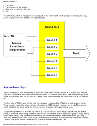
![A guide to digital music #2
MIDI interface for keyboards
[top]
A musical keyboard can be connected to the sound card with a connector. That is called a MIDI
interface. You can buy special PC musical keyboards, or you can use one of the keyboards which are
available in music stores. It will work as long as the MIDI connectors match.
You connect your DIN connector to the piano keyboard. In the other end of the cable is a DB15
connector to the sound card. Then you can play from the piano keyboard through the sound card. Of
course it requires a program which can handle music, but it works.
I have tried it myself. The Sound Blaster AWE64 Gold comes with the program Cubasis. Once I
connected an old and cheap piano keyboard (with built-in rhythm box) to the sound card, and
everything worked through Cubasis. The keyboard acted as a "Local Synthesizer" in the program
settings.
This keyboard is especially designed for the PC.
Links
[top]
Here is a link to Anselmo Salzani, who tries to create exciting music in the MIDI format. His page also
includes a lot of other interesting music links: Brazilian MIDI music.
And a Dane: Anders Kornerups MIDI music
http://www.karbosguide.com/hardware/module7d2.htm (3 of 4)7/27/2004 4:07:08 AM](https://image.slidesharecdn.com/computerrepair-acompleteillustratedguidetopchardware-140318001250-phpapp01/85/Computer-repair-_a_complete_illustrated_guide_to_pc_hardware-206-320.jpg)
![A guide to digital music #2
q Next page
q Previous page
Learn more [top]
Click for Module 3b about CPU improvements
Click for Module 3c about the 5th generations CPUs (Pentiums etc.)
Click for Module 3d about the clock frequencies
Click for Module 3e about 6th generations CPUs (Pentium IIs etc.)
[Main page] [Contact] [Karbo's Dictionary] [The Software Guides]
Copyright (c) 1996-2001 by Michael B. Karbo. www.karbosguide.com.
http://www.karbosguide.com/hardware/module7d2.htm (4 of 4)7/27/2004 4:07:08 AM](https://image.slidesharecdn.com/computerrepair-acompleteillustratedguidetopchardware-140318001250-phpapp01/85/Computer-repair-_a_complete_illustrated_guide_to_pc_hardware-207-320.jpg)
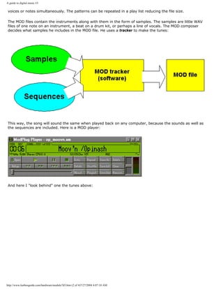
![A guide to digital music #3
You can download great music in the MOD format. The files are named .MOD or .XM. The most incredible is
the file size. There obviously is a lot of compression in it, often you get more than a minute high quality
replay out of a MOD file of just 100 KB.
All you need is a little software:
Links
[top]
Visit this MOD site where you find players and other MOD stuff.
Also check Great Swedish music in MOD format.
q Next page
http://www.karbosguide.com/hardware/module7d3.htm (3 of 4)7/27/2004 4:07:10 AM](https://image.slidesharecdn.com/computerrepair-acompleteillustratedguidetopchardware-140318001250-phpapp01/85/Computer-repair-_a_complete_illustrated_guide_to_pc_hardware-210-320.jpg)
![A guide to digital music #3
q Previous page
Learn more [top]
Click for Module 3b about CPU improvements
Click for Module 3c about the 5th generations CPUs (Pentiums etc.)
Click for Module 3d about the clock frequencies
Click for Module 3e about 6th generations CPUs (Pentium IIs etc.)
[Main page] [Contact] [Karbo's Dictionary] [The Software Guides]
Copyright (c) 1996-2001 by Michael B. Karbo. www.karbosguide.com.
http://www.karbosguide.com/hardware/module7d3.htm (4 of 4)7/27/2004 4:07:10 AM](https://image.slidesharecdn.com/computerrepair-acompleteillustratedguidetopchardware-140318001250-phpapp01/85/Computer-repair-_a_complete_illustrated_guide_to_pc_hardware-211-320.jpg)
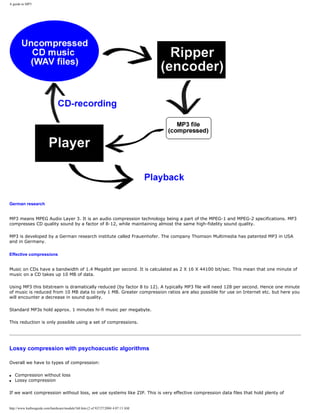
![A guide to MP3
Here you see my DVD-player which plays CD-ROMs filled with MP3 files:
Links
[top]
Get a MP3 player
You will have to find the MP3s yourself - start with www.mp3.com
Get a ripper from MusicMatch
Microsoft's new player " Windows Media Player " also plays MP3s.
q Next page
q Previous page
Learn more [top]
Click for Module 3b about CPU improvements
Click for Module 3c about the 5th generations CPUs (Pentiums etc.)
Click for Module 3d about the clock frequencies
Click for Module 3e about 6th generations CPUs (Pentium IIs etc.)
http://www.karbosguide.com/hardware/module7d4.htm (8 of 9)7/27/2004 4:07:13 AM](https://image.slidesharecdn.com/computerrepair-acompleteillustratedguidetopchardware-140318001250-phpapp01/85/Computer-repair-_a_complete_illustrated_guide_to_pc_hardware-219-320.jpg)
![A guide to MP3
[Main page] [Contact] [Karbo's Dictionary] [The Software Guides]
Copyright (c) 1996-2001 by Michael B. Karbo. www.karbosguide.com.
http://www.karbosguide.com/hardware/module7d4.htm (9 of 9)7/27/2004 4:07:13 AM](https://image.slidesharecdn.com/computerrepair-acompleteillustratedguidetopchardware-140318001250-phpapp01/85/Computer-repair-_a_complete_illustrated_guide_to_pc_hardware-220-320.jpg)
![A guide to digital music #5
Now you just select the melody, and Netscape will play it. You need not be on the Internet, you
just use the browser to play the music. The music can run in the background all day, while you
do something else.
If the SKP files are associated with Netscape, you can play them directly by double clicking on
them.
Links
[top]
At the SSEYO Koan home page you can find plugins, tunes and information, including software to
let you write your own Koan music.
q Next page
http://www.karbosguide.com/hardware/module7d5.htm (4 of 5)7/27/2004 4:07:15 AM](https://image.slidesharecdn.com/computerrepair-acompleteillustratedguidetopchardware-140318001250-phpapp01/85/Computer-repair-_a_complete_illustrated_guide_to_pc_hardware-224-320.jpg)
![A guide to digital music #5
q Previous page
Learn more [top]
Click for Module 3b about CPU improvements
Click for Module 3c about the 5th generations CPUs (Pentiums etc.)
Click for Module 3d about the clock frequencies
Click for Module 3e about 6th generations CPUs (Pentium IIs etc.)
[Main page] [Contact] [Karbo's Dictionary] [The Software Guides]
Copyright (c) 1996-2001 by Michael B. Karbo. www.karbosguide.com.
http://www.karbosguide.com/hardware/module7d5.htm (5 of 5)7/27/2004 4:07:15 AM](https://image.slidesharecdn.com/computerrepair-acompleteillustratedguidetopchardware-140318001250-phpapp01/85/Computer-repair-_a_complete_illustrated_guide_to_pc_hardware-225-320.jpg)
![An illustrated Guide to Scanners and Digital Cameras
Read about digital sound and music in Module 7d .
[Main page] [Contact] [Karbo's Dictionary] [The Software Guides]
Copyright (c) 1996-2001 by Michael B. Karbo. www.karbosguide.com.
http://www.karbosguide.com/hardware/module8a1.htm (2 of 2)7/27/2004 4:07:17 AM](https://image.slidesharecdn.com/computerrepair-acompleteillustratedguidetopchardware-140318001250-phpapp01/85/Computer-repair-_a_complete_illustrated_guide_to_pc_hardware-227-320.jpg)
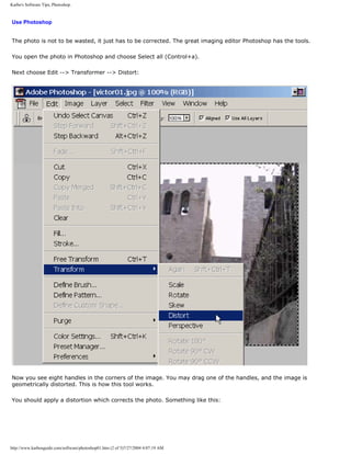
![Karbo's Software Tips, Photoshop.
You always apply a transformation by hitting [Enter]. The the image is OK from a geometrically point of view:
http://www.karbosguide.com/software/photoshop01.htm (3 of 5)7/27/2004 4:07:19 AM](https://image.slidesharecdn.com/computerrepair-acompleteillustratedguidetopchardware-140318001250-phpapp01/85/Computer-repair-_a_complete_illustrated_guide_to_pc_hardware-230-320.jpg)
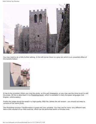
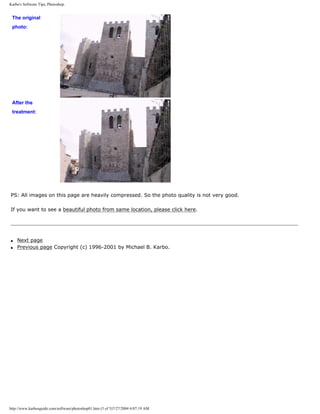
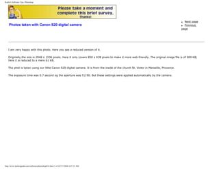
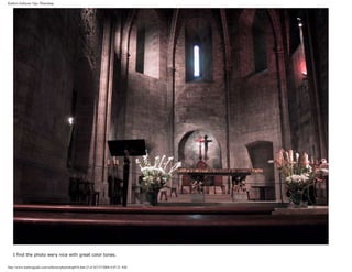

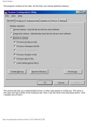
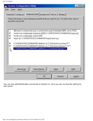
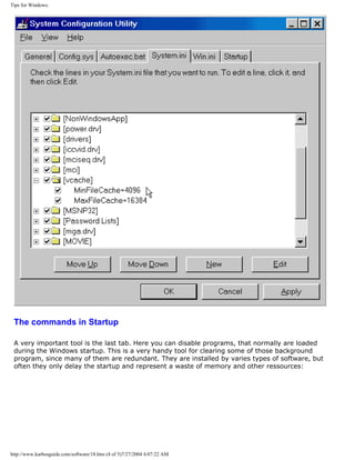
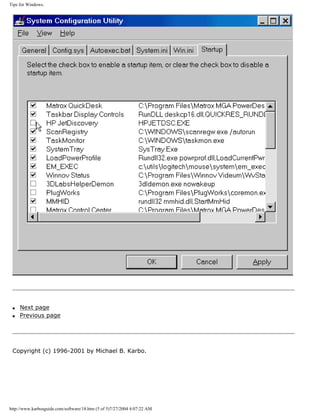
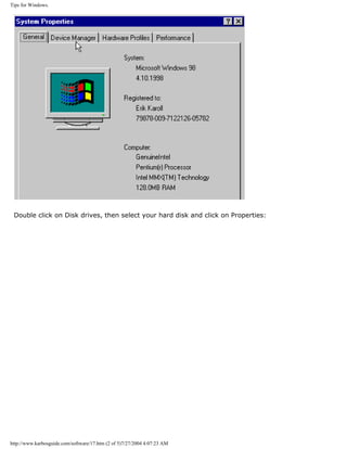
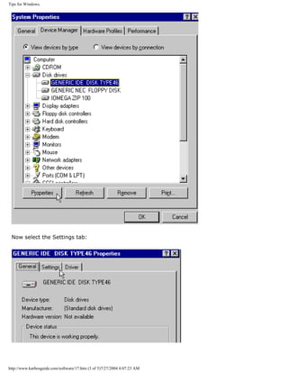
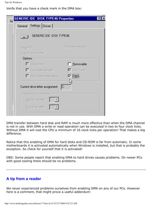
![Tips for Windows.
You forgot one very important part that is required to enable DMA in Windows 98. After you
check the DMA box in the device mamager- disk drive window, do the following:
To make sure that DMA doesn't cause any internal Windows conflicts (assuming the drive
supports DMA), you are going to need to add these lines to the Mshdc.inf file at the bottom of
the [ESDI_AddReg] tag (if they aren't already there):
HKR,,IDEDMADrive0,3,01
HKR,,IDEDMADrive1,3,01
HKR,,IDEDMADrive2,3,01
HKR,,IDEDMADrive3,3,01
Only add the bottom two lines (the bolded ones) if you have more than two IDE drives (HD/
CD devices) connected to your system.
Within the DISKDRV.INF file, add the same lines under the [DiskReg] entry. If the lines are
already there, you don't need to continue on, because you are done. Otherwise, copy the two
modified files to another directory.
I recommend creating a new directory named inf2 in your windows system directory. Then
remove all of the items under the Hard Drive Controllers and all of the Hard Drives (only hard
drives, not removable media) from under the Disk Drives heading.
Then reboot your system.
When the computer's Hardware Wizard pops up to reinstall the drives, set it so you can
choose from the compatible drivers list and check the date on the drivers. They should be for
the same day you modified them. If they are, great, use them, otherwise you will need to
point them at the copies (the inf folder is invisible at this point, which is why you need the
second copies) and use those. Thanks guys!
David Gillespie
--- We hope this will be useful, and thanks to David!
q Next page
q Previous page
Copyright (c) 1996-2001 by Michael B. Karbo.
http://www.karbosguide.com/software/17.htm (5 of 5)7/27/2004 4:07:23 AM](https://image.slidesharecdn.com/computerrepair-acompleteillustratedguidetopchardware-140318001250-phpapp01/85/Computer-repair-_a_complete_illustrated_guide_to_pc_hardware-246-320.jpg)
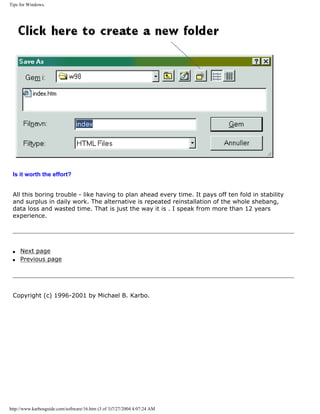
![Tips for Windows.
Karbosguide.com. Software Tip 15
MacroExpress 98
q Next page
q Previous
page
This program is quite smart. It is about developing macros, which can handle the repetitive keyboard/mouse
operations.
A small, very simple example: If I write my home pages in an editor like Composer; I have to forever format
headings with the heading 1, 2, and 3 formats. The only way I can do that is through the menu or tool bar.
To grab the mouse every time is not practical while I write, and menu choices require some complicated
keyboard entries. All I wish is to make:
q [Alt]+1 give heading 1
q [Alt]+2 give heading 2
q [Alt]+3 give heading 3
That's how the styles work in Word. But with MacroExpress 98 it is very easy to add this functionality. You
see the screen image here:
You can select whether the macros will work in all programs, or whether they only work in a designated
program. Probably the last option is the smartest. I need to add that the program places some demands on
the user. It takes a little while to understand how it works. You see MacroExpress 98 records an image of for
example your mouse movements. So if you for example change the menus or program set-up, you might
risk that the results are quite different when you play the macro. Here is a brief description:
You start the recording in this screen image. Here I will add a macro to the keyboard command [Alt]+q:
http://www.karbosguide.com/software/15.htm (1 of 5)7/27/2004 4:07:26 AM](https://image.slidesharecdn.com/computerrepair-acompleteillustratedguidetopchardware-140318001250-phpapp01/85/Computer-repair-_a_complete_illustrated_guide_to_pc_hardware-250-320.jpg)
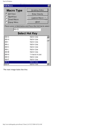
![Tips for Windows.
Then the macro is recorded through the keyboard/mouse commands for that program. When you are
finished, you close by pressing [Alt]+q (in this case).
Then the macro works. When you are in the given program you press [Alt]+q, and the macro plays. If you
used the mouse during recording, you will see (surely to your great surprise) the mouse work on its own. It
takes a little while, but the macro works just like you recorded it.
Now it just remains to speed it up. I do that by double clicking on the macro. The first command regards the
speed, and I set the value to 0.01, to make the macro work at the speed of lightning. I can also delete all
Delays:
http://www.karbosguide.com/software/15.htm (3 of 5)7/27/2004 4:07:26 AM](https://image.slidesharecdn.com/computerrepair-acompleteillustratedguidetopchardware-140318001250-phpapp01/85/Computer-repair-_a_complete_illustrated_guide_to_pc_hardware-252-320.jpg)
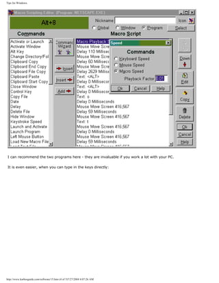
![Tips for Windows.
Karbosguide.com. Software Tip 14
Windows Autotexts
q Next page
q Previous
page
It is terribly impractical to have to repeat the same operations over and over again. Some
programs (like Word) gives lots of options for customizing their execution with macros,
autotexts, and keyboard shortcuts. You can read about that in "Word 97 short course," where
I have given much emphasis on these options.
But other - many other- Windows programs do not offer these macro etc. options. That is the
case with a program like Composer, which I use to write my home pages. There is no
question that the program is excellent for writing home pages. But its functionality is quite
primitive. There are hardly any keyboard shortcuts, and no macros. Many Windows programs
are designed like this, and it can really be quite trying to fight your way through a larger
assignment.
You can get help. I am talking about two programs, which can spruce up any Windows
program. I can equip Composer with just the same autotexts and keyboard shortcuts, which I
enjoy so much in Word:
q ShortKeys 98
q MacroExpress 98
Both programs require some getting used to, but then they really work. Unfortunately only
for 30 days, unless you pay for them. Let me show you some examples of how I use them.
First the simplest of the programs:
ShortKeys 98
[top]
ShortKeys is quite similar to the Autotext function in the word processing program Word. The
idea is that you make an abbreviation of those words or expressions you use most frequently.
The smart thing about ShortKeys is that it works in all Windows programs. Look at this
illustration:
http://www.karbosguide.com/software/14.htm (1 of 2)7/27/2004 4:07:26 AM](https://image.slidesharecdn.com/computerrepair-acompleteillustratedguidetopchardware-140318001250-phpapp01/85/Computer-repair-_a_complete_illustrated_guide_to_pc_hardware-255-320.jpg)
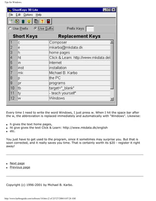
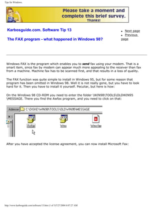
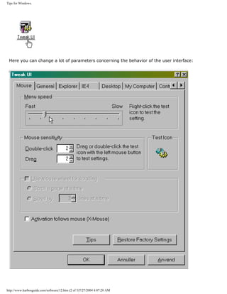
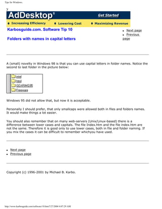
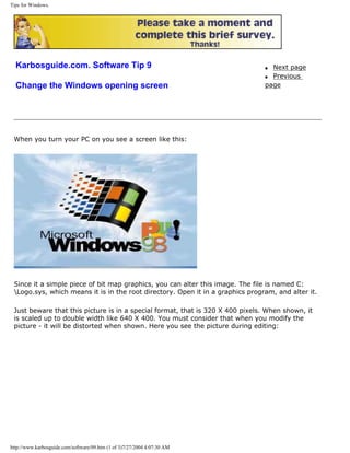
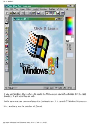
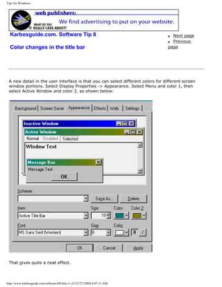
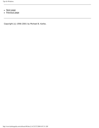
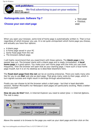
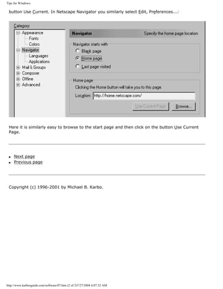
![Tips for Windows.
Karbosguide.com. Software Tip 6
Fixed folder for downloading in Internet Explorer
q Next page
q Previous
page
When you are in the Internet with Internet Explorer and look at a file, which is not a home
page, you have the option to download the file. But in which folder does it end up? Maybe
you have noticed that it appears to be random. Or maybe you have discovered that it always
saves in the last folder you downloaded to. You see Windows saves that information.
I want Internet Explorer to always suggest C:temp for saving downloads, since I always use
that folder for this purpose. So how do I make the Internet Explorer program accept that?
Unfortunately I need to go to the registry database. That is just a small thing, and here I will
show you how:
Open a new text document in Notepad, or whatever program you use for that kind of thing.
Then write these lines, precisely as you see them here (It is easier to copy them from here,
then you will get no errors):
REGEDIT4
[HKEY_USERS.DEFAULTSoftwareMicrosoftInternet Explorer]
"Download Directory"="C:temp"
Here you see it:
Now save the file, for example on the desktop. It MUST have the suffix .REG. I call it
ie40download.reg. The moment you rename the suffix, the file will be included in the registry
http://www.karbosguide.com/software/06.htm (1 of 2)7/27/2004 4:07:32 AM](https://image.slidesharecdn.com/computerrepair-acompleteillustratedguidetopchardware-140318001250-phpapp01/85/Computer-repair-_a_complete_illustrated_guide_to_pc_hardware-273-320.jpg)

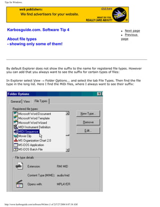
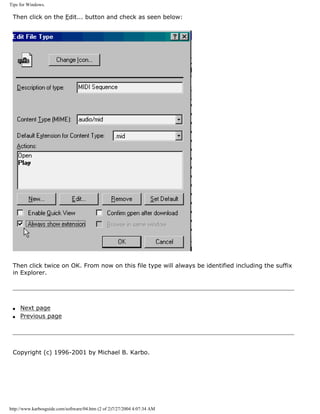
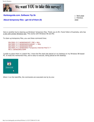
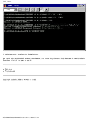
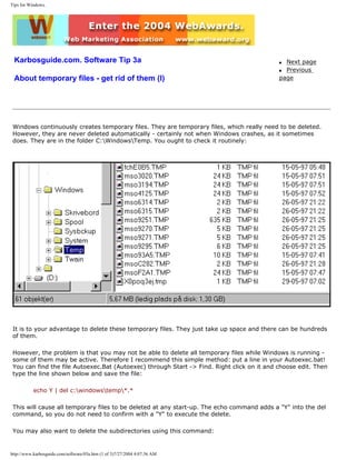
![Tips for Windows.
deltree /y c:windowstemp*.*
Use the Autoexec.bat
Windows also has tools for cleaning the harddisk. However I still recommend the following addition to the
Autoexec.bat. This only works in Windows 98, since Windows Me has no Autoexec.bat.
Autoexec.bat is a text file, and it has to be to be edited. If you worked with your PC ten years ago, you
would not ask what Autoexec.bat is. We used it all the time to tweak more free memory out of the start-
up.
Autoexec.bat is the central start-up file in any DOS-based computer. It holds a number of "lines" (written
in simple text).
Each line in Autoexec.bat is to be executed during the start-up - one by one. Hence the file type is BAT,
which stands for batch. A batch file holds one or several of lines of commands. And here we add three lines
into the Autoexec.bat.
To open Autoexec.bat, you find Windows Explorer and highlight C: (the root directory) in the left frame.
In the right frame you find Autoexec.bat. Highlight it and make a rightclick on it. Then choose edit, and it
is opened for you in Notepad.
Make your changes and save the file, which then works after re-boot.
Using Autoexec.bat is smart since it cleans up every time you boot the pc. The first line to add:
deltree /y C:Windowstemp*.*
This line deletes all the temporary Internet files including the subdirectories, which all the time is created
in C:WINDOWSTemporary Internet Files:
deltree /y C:WindowsTEMPOR~1*.*
Finally add
C:WINDOWSCOMMANDdeltree /y C:Windowscookies*.*
This line clears out the cookies, which my browser collects all the time. The PC has to reboot for the
Autoexec.bat to work. You can monitor the deletion on screen during the start up (hit [pause] key to
freeze the screen).
Three lines
You may use these three lines in my Autoexec.bat:
C:WINDOWSCOMMANDdeltree /y C:Windowstempor~1*.*
C:WINDOWSCOMMANDdeltree /y c:windowstemp*.*
C:WINDOWSCOMMANDdeltree /y C:Windowscookies*.*
The first line empties the browsers cache - a good thing. The second line cleans up after Windows in
general. The third line clears out the cookies, which the browser collects all the time.
http://www.karbosguide.com/software/03a.htm (2 of 3)7/27/2004 4:07:36 AM](https://image.slidesharecdn.com/computerrepair-acompleteillustratedguidetopchardware-140318001250-phpapp01/85/Computer-repair-_a_complete_illustrated_guide_to_pc_hardware-283-320.jpg)
![Tips for Windows.
Software Tip 2b
About the Disk Cache
q Next page
q Previous
page
Especially in Windows versions 95 and 98 it is important to understand the of the relationship between:
q Size of and control of Disk cache
q The free memory
q The size of the swap file
What is disk cache?
The cache is a portion of RAM, reserved for cache (buffer) for the hard disk. The disk cache is necessary, since it speeds up the hard
disk a lot. However, it should not be bigger than 8 or 16 MB.
The problem is that the disk cache really gobbles up RAM. In Windows 98 it can easily eat up 20-25% of your RAM. An that is a total
waste of RAM.
In Windows 98 you can limit the size of your cache. This is done by editing the file System.Ini, which is found in C:Windows. Double
click on it and scroll down until you reach the text [vcache].
Then type in the two lines you see below and save the file. Do it soon. This is important!
[Non Windows App]
[vcache]
MinFileCache=8096
MaxFileCache=8096
[display]
The change takes effect when you restart Windows. I am convinced that 8 MB disk cache is sufficient - at least when you use the
FAT32 file system.
If you use Windows 95 with the old FAT16 file system, you should probably maintain just 1 or 2 MB of disk cache.
In Fat 32 the vcache holds a permanent copy of the whole FAT table, which occupies full 2 MB under the FAT32 file system. With this
size FAT the Vcache has to be 4 MB big, if there shall be room for other things besides the FAT.
Read about file systems and about the cache copy of FAT in same module.
The System Monitor
You can watch your use of memory with the excellent tool resource meter . You find it by going to: Start -> Programs -> Accessories -
> System Tools -> System Monitor. You can add elements in the edit menu. That will allow you to see available memory and the swap
file, as illustrated below (you may print this page, although the figure is in Danish):
http://www.karbosguide.com/software/02b.htm (1 of 2)7/27/2004 4:07:36 AM](https://image.slidesharecdn.com/computerrepair-acompleteillustratedguidetopchardware-140318001250-phpapp01/85/Computer-repair-_a_complete_illustrated_guide_to_pc_hardware-285-320.jpg)
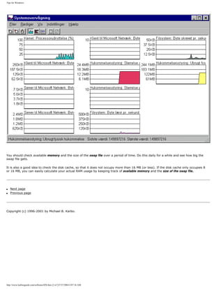

![An illustrated Guide to RAM.
Please click the banners to support our work!
KarbosGuide.com. Module 2e1.
About RAM
Here you can read about:
q What is RAM?
q About RAM types
On the following pages:
q About SIMMs
q DIMMs
q PC100 RAM and further
q Rambus
q DDR
q Next page
q Previous page
What is RAM? [top]
This page should be read together with modules 2a, 2b, 2c, and 2d,
which deal with system board, system bus, I/O bus and chip sets.
When we talk about motherboard and chip sets, we cannot ignore
RAM. Warning: RAM and RAM chips is a very complicated, technical
subject area. I can in no way give a complete, comprehensive
description of this subject.
Please support our
sponsor.
http://www.karbosguide.com/hardware/module2e1.htm (1 of 6)7/27/2004 4:07:39 AM](https://image.slidesharecdn.com/computerrepair-acompleteillustratedguidetopchardware-140318001250-phpapp01/85/Computer-repair-_a_complete_illustrated_guide_to_pc_hardware-289-320.jpg)
![An illustrated Guide to RAM.
RAM is our working memory storage. All the data, which the PC uses and works with during
operation, are stored here. Data are stored on drives, typically the hard drive. However, for
the CPU to work with those data, they must be read into the working memory storage, which
is made up of RAM chips. To examine RAM, we need to look at the following:
q RAM types (FPM, EDO, ECC, and SD RAM)
q RAM modules (SIMM and DIMM) in different versions
q RAM and the system bus
First, let us look back in time. Not too many years ago, Bill Gates said, that with 1 MB RAM,
we had a memory capacity, which would never be fully utilized. That turned out to be untrue.
Historical review
Back in the 80s, PCs were equipped with RAM in quantities of 64 KB, 256 KB, 512 KB and
finally 1 MB. Think of a home computer like Commodore 64. It had 64 KB RAM, and it worked
fine.
Around 1990, advanced operating systems, like Windows , appeared on the market, That
started the RAM race. The PC needed more and more RAM. That worked fine with the 386
processor, which could address larger amount of RAM. The first Windows operated PCs could
address 2 MB RAM, but 4 MB soon became the standard. The race has continued through the
90s, as RAM prices have dropped dramatically.
Today. it would be foolish to consider less than 32 MB RAM in a PC. Many have much more.
128 MB is in no way too much for a "power user" with Windows 95/98, it is important with
plenty of RAM. Click here to read about the swap file and RAM considerations. Windows 98 is
a little better at handling memory, but still a lot af RAM is a good thing.
RAM types
[top]
The traditional RAM type is DRAM (dynamic RAM). The other type is SRAM (static RAM).
SRAM continues to remember its content, while DRAM must be refreshed every few milli
seconds. DRAM consists of micro capacitors, while SRAM consists of off/on switches.
Therefore, SRAM can respond much faster than DRAM. SRAM can be made with a rise time as
short as 4 ns. It is used in different versions in L2 cache RAM (for example pipe line BURST
Cache SRAM).
DRAM is by far the cheapest to build. Newer and faster DRAM types are developed
http://www.karbosguide.com/hardware/module2e1.htm (2 of 6)7/27/2004 4:07:39 AM](https://image.slidesharecdn.com/computerrepair-acompleteillustratedguidetopchardware-140318001250-phpapp01/85/Computer-repair-_a_complete_illustrated_guide_to_pc_hardware-290-320.jpg)
![An illustrated Guide to RAM.
continuously. Currently, there are at least four types:
q FPM (Fast Page Mode)
q ECC (Error Correcting Code)
q EDO (Extended Data Output)
q SDRAM (Synchronous Dynamic RAM)
A brief explanation of DRAM types
[top]
FPM was the traditional RAM for PCs, before the EDO was introduced. It is mounted in SIMM
modules of 2, 4, 8, 16, or 32 MB. Typically, it is found in 60 ns or 70 ns versions. 60 ns is the
fastest and the one to use. You cannot mix different speeds on the same Pentium
motherboard.
EDO (Extended Data Out) RAM is an improvement of FPM RAM. Data are read faster. EDO
extends the time that output data is valid, which betters timing issues between the CPU and
RAM and this way improves the performance.
By switching from FPM to EDO, one could expect a performance improvement of 2 to 5
percent. EDO RAM was usually sold in 60 ns versions. A 50 ns version was available at higher
cost.
EDO has now been replaced by the even faster SDRAM.
ECC RAM is a special error correcting RAM type. It is especially used in servers.
SDRAM (synchronous DRAM)): The replacement for DRAM, FPM, and EDO RAM types. SDRAM
"locks" (synchronizes) the memory access to the CPU clock. This way we get faster data
transfer. While one portion of data is tranported to the CPU another can be being prepared
for transfer.
SDRAM comes only in 64 bit modules (long 168 pin DIMMs). SDRAM has a access time of
only 6-12 ns. The performance improvement over EDO RAM was a mere 5 percent running at
66 MHz. At 100 and 133 MHz it proves better.
DDR RAM is clock doubled version of SDRAM, which is replacing SDRAM during 2001-2002.
RAMBUS (RDRAM) is a more futuristic RAM type. Intel and others had great expectations
from this type, but it flopped in 2000-2001.
8 or 9 bits per byte?
http://www.karbosguide.com/hardware/module2e1.htm (3 of 6)7/27/2004 4:07:39 AM](https://image.slidesharecdn.com/computerrepair-acompleteillustratedguidetopchardware-140318001250-phpapp01/85/Computer-repair-_a_complete_illustrated_guide_to_pc_hardware-291-320.jpg)
![An illustrated Guide to RAM.
Normally you figure 8 bits to one byte. For many years, a ninth bit has been added as parity
bit in the RAM blocks to verify correct transmission. That way you have to transmit 9 bits, to
store 8 bits in the old 30 pin RAM chips. And it takes 36 bits to store 32 bits in the larger 72
pin chips, which increases the cost of the RAM chip by about 12%.
If your motherboard requires 36 bit modules, you must respect that. Fortunately, most
system boards accepts 32 bit modules, so this creates no problems.
RAM and motherboard
[top]
You cannot freely install your desired RAM type. RAM is controlled by the chip set on the
motherboard, so you must install a type, which matches your motherboard. Furthermore,
RAM chips come in different sizes, which must match the system board.
On modern system boards, RAM is installed on SIMM or DIMM modules. Before, small
individual DRAMs were used. There was usually room for 36 small chips on the system board.
That made it cumbersome to install new RAM. Then, someone figured out to install RAM chips
on cards, which are easily installed. First came the SIPP modules. They had multiple pins,
which fit in the motherboard. Since then came the SIMM modules. They are mounted on a
card, which has an edge connector. They fit in sockets on the motherboard, and anyone can
install them.
RAM speeds
[top]
RAM speed is measured in ns (nano seconds). The fewer ns, the faster is the RAM. Years ago,
RAM came in 120, 100 and 80 ns. Today, we are talking about 60 ns and faster.
It becomes complicated to describe the relationship between RAM speed and the ability of the
system bus to utilize fast RAM. I will gloss over that. But here is a table which illustrates RAM
speed, relative to clock speed:
Clock speed Time per clock
tick
20 MHz 50 ns
25 MHz 40 ns
33 MHz 30 ns
50 MHz 20 ns
http://www.karbosguide.com/hardware/module2e1.htm (4 of 6)7/27/2004 4:07:39 AM](https://image.slidesharecdn.com/computerrepair-acompleteillustratedguidetopchardware-140318001250-phpapp01/85/Computer-repair-_a_complete_illustrated_guide_to_pc_hardware-292-320.jpg)
![An illustrated Guide to RAM.
66 MHz 15 ns
100 MHz 10 ns
133 MHz 6 ns
Peak Bandwidth
[top]
Here you see the maximal peak bandwidth of the three well known RAM types. The figures
illustrates the absolutely maximal transfer from RAM to the L2-cache - in peaks, not as
continuously transferred.
RAM type Max. peak bandwidth
FPM 176 MB/sec
EDO 264 MB/sec
SD 528 MB/sec
q Next page
q Previous page
Learn more [top]
Also see module 3. An illustrated Guide to CPUs from 8086 to the Pentium-III.
Read module 5a about expansion cards, where we evaluate the I/O buses from the port side.
Read module 5b about AGP and module 5c about Firewire.
Read module 7a about monitors, and 7b on graphics card.
Read module 7c about sound cards, and 7d on digital sound and music.
[Main page] [Contact] [Karbo's Dictionary] [The Software Guides]
http://www.karbosguide.com/hardware/module2e1.htm (5 of 6)7/27/2004 4:07:39 AM](https://image.slidesharecdn.com/computerrepair-acompleteillustratedguidetopchardware-140318001250-phpapp01/85/Computer-repair-_a_complete_illustrated_guide_to_pc_hardware-293-320.jpg)

![An illustrated Guide to RAM.
KarbosGuide.com. Module 2e2
About SIMM RAM
The contents:
q About SIMMs
q Number of chips per module
q Buswidth 32 bit
q Next page
q Previous page
SIMMs [top]
SIMM (Single Inline Memory Modules) were first made in 8 bit editions. They were small cards
with 1, 2 or 4 MB RAM. They were connected to the motherboard with a 30 pin edge
connector. The modules were 8 bit wide. This meant that 16 bit processors (286 and 386SX)
needed 2 SIMMs in a pair. Thus, there was room for two modules in what is called a bank.
32 bit processors (386DX and 486) need 4 of the small 8 bit SIMMs in a bank, since their banks
are 32 bit wide. So, on a typical 1st generation 486 motherboard, you could install 4 X 1 MB, 4
X 2 MB, or 4 X 4 MB in each bank. If you only had one bank (with room for 4 modules), it was
expensive to increase the RAM, because you had to discard the old modules.
http://www.karbosguide.com/hardware/module2e2.htm (1 of 4)7/27/2004 4:07:41 AM](https://image.slidesharecdn.com/computerrepair-acompleteillustratedguidetopchardware-140318001250-phpapp01/85/Computer-repair-_a_complete_illustrated_guide_to_pc_hardware-295-320.jpg)
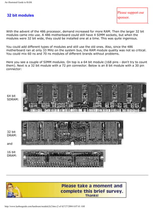
![An illustrated Guide to RAM.
Please click the banners to support our work!
Number of chips per module
[top]
Some SIMMs have more chips on the module than others. Looking at just the 32 bit modules,
we find modules with 2, 4, 8 or chips on each side. SIMMs with 2 MB, 8 MB and 32 MB are
double sided. There are chips on both sides of the module, and all these chips are 16 Mbit ones.
The newest DIMM-modules holds 64 Mbit RAM chips. This way a 32 MB module is made of only
4 chips since 4 X 64 / 8 = 32.
Pentium motherboard with SIMMs
On the Pentium motherboard, the system bus is 64 bit wide. Therefore, the 32 bit SIMMs are
installed in pairs. Since the standard motherboard only has two banks with a total of four SIMM
sockets, RAM expansion possibilities are limited. NOTE: never use different speed RAM modules
on the Pentium motherboard. All modules must have the same speed. Here you see a few
configurations on an old Pentium motherboard with four SIMM sockets:
Bank 1 Bank 2 Total RAM
16 MB + 16 MB - 32 MB
16 MB + 16 MB 32 MB + 32 MB 96 MB
32 MB + 32 MB 32 Mb + 32 MB 128 MB
Certain motherboards (like TYAN) have 6 or 8 SIMM sockets. That provides more RAM
expansion flexibility.
q Next page
q Previous page
Learn more [top]
http://www.karbosguide.com/hardware/module2e2.htm (3 of 4)7/27/2004 4:07:41 AM](https://image.slidesharecdn.com/computerrepair-acompleteillustratedguidetopchardware-140318001250-phpapp01/85/Computer-repair-_a_complete_illustrated_guide_to_pc_hardware-297-320.jpg)
![An illustrated Guide to RAM.
An illustrated Guide to CPUs from 8086 to the Pentium-III: Module 3.
Read module 5a about expansion cards, where we evaluate the I/O buses from the port side.
Read module 5b about AGP and module 5c about Firewire.
Read module 7a about monitors, and 7b on graphics card.
Read module 7c about sound cards, and 7d on digital sound and music.
[Main page] [Contact] [Karbo's Dictionary] [The Software Guides]
Copyright (c) 1996-2001 by Michael B. Karbo. www.karbosguide.com.
http://www.karbosguide.com/hardware/module2e2.htm (4 of 4)7/27/2004 4:07:41 AM](https://image.slidesharecdn.com/computerrepair-acompleteillustratedguidetopchardware-140318001250-phpapp01/85/Computer-repair-_a_complete_illustrated_guide_to_pc_hardware-298-320.jpg)
![An illustrated Guide to RAM.
Please click the banners to support our work!
KarbosGuide.com. Module 2e3.
About new fast RAM
The contents:
q DIMMs
q PC100 RAM
q PC133 and VC133
q Intel and PC133
On the following pages:
q Rambus
q DDR
q Next page
q Previous page
DIMMs [top]
The most used modern RAM type, SDRAM is made in 64 bit wide modules called DIMMs (Dual
Inline Memory Module).
They have a 168 pin edge connector. Here you see one module:
Please support our
sponsor.
http://www.karbosguide.com/hardware/module2e3.htm (1 of 4)7/27/2004 4:07:43 AM](https://image.slidesharecdn.com/computerrepair-acompleteillustratedguidetopchardware-140318001250-phpapp01/85/Computer-repair-_a_complete_illustrated_guide_to_pc_hardware-299-320.jpg)
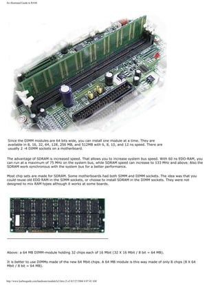
![An illustrated Guide to RAM.
Fast RAM
[top]
Intel have managed to speed up the processors power by factor 200 times the last ten years. That is a lot, but it is a
problem that RAM memory technology only has improved by factor 20 in the same period.
Today we hope and dream of new fast RAM types, that will help us to get the full potential from our powerful PCs.
PC100 RAM
The first attempt to improving RAM speed was the PC100 standard. With chip sets like BX the system bus speed has
come up to 100 MHz. Hence Intel has made a new standard called PC100. Only 8 ns SD-RAM modules that are
constructed according to these standards are guaranteed to work at 100 MHz. In some articles this RAM is described at
125 SD-RAM.
SPD
The new DIMM-modules include a EPROM-chip holding information about the module. This little 8-pin chip works as a
SPD (Serial Presence Detect) - a unit storing information about the RAM type. The idea is that BIOS can read this
information and this way tune the system bus and the timings for a perfect CPU-RAM performance.
You can find a program, that tests the contents of the SPD at this c't homepage. It works with the Intel chip sets
holding a 82371 south bridge like BX and GX.
Another program is called DIMM_ID.
PC133
The PC133 RAM running at 133 MHz is the latest version of SDRAM. Specifications are made by VIA, Micron, NEC,
Samsung, SIS, Acer Labs and other vendors. The first production (from Corsair, June 1999) used 7.5 ns RAM modules
from Micron.
VIA supports the PC133 RAM with their Apollo Pro Plus chip set (693A). Later they launched support for PC266 DDR
RAM!
Also AMD's K7 Athlon may use PC133 RAM with the VIA KX133Pro chipset.
VC133
Virtual Channel 133 is another flavour of the PC133 standard. The modules holds a small cache of superfast SRAM.
According to tests, these modules perform very well, but due to unknown reasons, it never became popular.
Intel and PC133
Originally Intel planned to by-pass PC133 RAM in their roadmaps. They intended to migrate from PC100-based chip sets
(like BX) to Rambus-based chip sets (like i820).
For a period of 12 months in 1999-2000, Intel experienced several disastrous incidents from their attempt to implement
http://www.karbosguide.com/hardware/module2e3.htm (3 of 4)7/27/2004 4:07:43 AM](https://image.slidesharecdn.com/computerrepair-acompleteillustratedguidetopchardware-140318001250-phpapp01/85/Computer-repair-_a_complete_illustrated_guide_to_pc_hardware-301-320.jpg)
![An illustrated Guide to RAM.
Rambus in chip sets and motherboards. During this period they were forced (by taiwanese motherboard manufactures)
to adapt the PC133 standard.
The chip set i815 was the result of this revision of strategies.
Intel's problem is that they have "sold their soul" to Rambus Inc. According to their agreement, until 2003 Intel can
only implement other RAM types than RDRAM if the bandwidth is less than 1 GB/sec. This agreement does not include
server chipsets, from what we understand.
q Next page
q Previous page
Learn more [top]
Read module 5a about expansion cards, where we evaluate the I/O buses from the port side.
Read module 5b about AGP and module 5c about Firewire.
Read module 7a about monitors, and 7b on graphics card.
Read module 7c about sound cards, and 7d on digital sound and music.
[Main page] [Contact] [Karbo's Dictionary] [The Software Guides]
Copyright (c) 1996-2001 by Michael B. Karbo. www.karbosguide.com.
http://www.karbosguide.com/hardware/module2e3.htm (4 of 4)7/27/2004 4:07:43 AM](https://image.slidesharecdn.com/computerrepair-acompleteillustratedguidetopchardware-140318001250-phpapp01/85/Computer-repair-_a_complete_illustrated_guide_to_pc_hardware-302-320.jpg)
![An illustrated Guide to RAM.
Please click the banners to support our work!
KarbosGuide.com. Module 2e4
About Rambus RAM
The contents:
q Rambus
q High clock rates
q Next page
q Previous page
Rambus RDRAM
[top]
While the CPUs has become around 200 times faster in ten years, the RAM
performance has only gone up 20 times. So we need new RAM types. But which?
Many vendors decided to go for DDR RAM as described in . Where DDR RAM is a
development of the existing SDRAM technology, Intel choose RDRAM, which
represents a much more revolutionary change in RAM design.
Please support our
sponsor.
Intel and RDRAM without succes
http://www.karbosguide.com/hardware/module2e4.htm (1 of 5)7/27/2004 4:07:45 AM](https://image.slidesharecdn.com/computerrepair-acompleteillustratedguidetopchardware-140318001250-phpapp01/85/Computer-repair-_a_complete_illustrated_guide_to_pc_hardware-303-320.jpg)
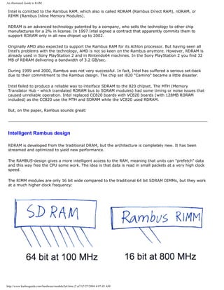
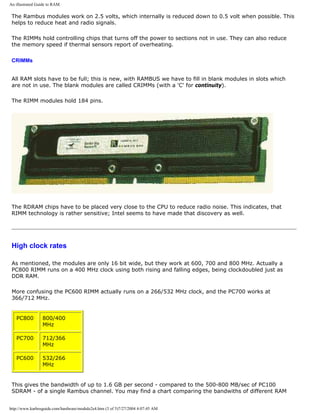
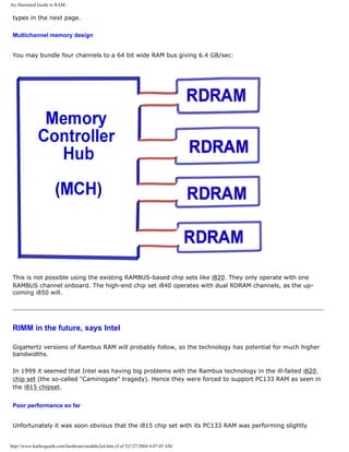
![An illustrated Guide to RAM.
better than the i820 chip set with its still very expensive RDRAM. You have to use dual Rambus channels
(as in upcomming Intel chip set i850 "Tehema") to benefit from a higher bandwidth. But this doubling is
also possible from using DDR RAM.
A test between a i840-based dual Rambus PC and a Micron DDR-based PC gave the same result; all
benchmarks were better on the DDR system.
So far Rambus RAM is of no big interest. It is too expensive, and there is nothing to gain from it.
However the Rambus technology stil is quite promising, but the prices has to come down, and it better
be soon. DDR RAM is closing in.
Intel claims that DDR is to slow for the new Pentium 4 processor. It would require dual channel DDR
RAM to get the required bandwidth. And dual channel DDR RAM meens a 128 bit wide bus, which is no
good solution. The north bridge and the motherboard would be loaded with hundreds of signal lines.
In 2001 RDRAM is being used with great success on the GB850 Pentium 4 board and RDRAM prices are
tumbling steadily.
RDRAM 2.0
Rambus plans to speed up the bandwith a factor two using a Quad Rambus Signaling Level. This should
happen without any increase in clock frequency.
q Next page
q Previous page
Learn more [top]
Read module 5a about expansion cards, where we evaluate the I/O buses from the port side.
Read module 5b about AGP and module 5c about Firewire.
Read module 7a about monitors, and 7b on graphics card.
Read module 7c about sound cards, and 7d on digital sound and music.
[Main page] [Contact] [Karbo's Dictionary] [The Software Guides]
Copyright (c) 1996-2001 by Michael B. Karbo. www.karbosguide.com.
http://www.karbosguide.com/hardware/module2e4.htm (5 of 5)7/27/2004 4:07:45 AM](https://image.slidesharecdn.com/computerrepair-acompleteillustratedguidetopchardware-140318001250-phpapp01/85/Computer-repair-_a_complete_illustrated_guide_to_pc_hardware-307-320.jpg)
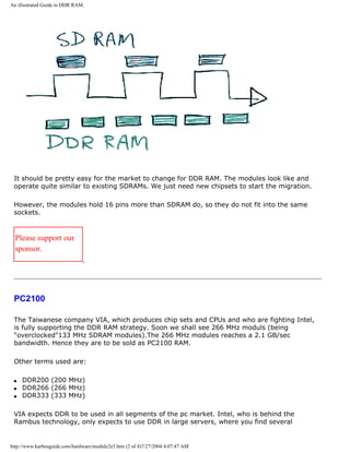
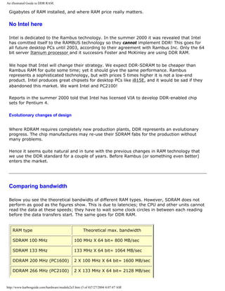
![An illustrated Guide to DDR RAM.
DDRAM 366 MHz (PC2600) 2 X 166 MHz X 64 bit= 2656 MB/sec
RDRAM 600 MHz 600 MHz X 16 bit= 1200 MB/sec
RDRAM 700 MHz 700 MHz X 16 bit= 1400 MB/sec
RDRAM 800 MHz 800 MHz X 16 bit= 1600 MB/sec
DDR-II
A new version of DDR RAM is scheduled for 2003. Using another technique, it should be
possible to double the performance!
q Next page
q Previous page
Learn more [top]
Read module 5a about expansion cards, where we evaluate the I/O buses from the port side.
Read module 5b about AGP and module 5c about Firewire.
Read module 7a about monitors, and 7b on graphics card.
Read module 7c about sound cards, and 7d on digital sound and music.
[Main page] [Contact] [Karbo's Dictionary] [The Software Guides]
Copyright (c) 1996-2001 by Michael B. Karbo. www.karbosguide.com.
http://www.karbosguide.com/hardware/module2e5.htm (4 of 4)7/27/2004 4:07:47 AM](https://image.slidesharecdn.com/computerrepair-acompleteillustratedguidetopchardware-140318001250-phpapp01/85/Computer-repair-_a_complete_illustrated_guide_to_pc_hardware-311-320.jpg)
![An illustrated Guide to CPUs from 8086 to Pentium-III
Please click the banners to support our work!
KarbosGuide.com. Module 3a1.
About CPUs
To understand the data processing methodology, an understanding of the design and function
of the CPU is essential. The following subjects will be covered on these pages.
The contents:
q What is a CPU?
q Intro to CPUs from 1st to 7th generation
q Next page
q Previous page
The module is divided in several sub modules, which all together
ought to be read as a unit. Please support our
sponsor.
What is a CPU?
[top]
The CPU is certainly the most important PC component. CPU stands for Central Processing
http://www.karbosguide.com/hardware/module3a1.htm (1 of 4)7/27/2004 4:07:50 AM](https://image.slidesharecdn.com/computerrepair-acompleteillustratedguidetopchardware-140318001250-phpapp01/85/Computer-repair-_a_complete_illustrated_guide_to_pc_hardware-312-320.jpg)
![An illustrated Guide to CPUs from 8086 to Pentium-III
Unit. Let us briefly study that name:
q It is a processor, because it processes (moves and calculates) data.
q It is central, because it is the center of PC data processing.
q It is a unit, because it is a chip, which contains millions of transistors.
Speed, speed, speed
Without the CPU, there would be no PC. Like all other hardware components, the CPUs are
continually undergoing further development. You can see the explosive technological
development in data processing most clearly in the development of newer and faster CPUs.
The CPUs have for years doubled their performance about every 18 months (Moore's Law),
and there are no indications that this trend will stop.
When we now look at all the CPUs from a broader perspective, we can see that:
q The CPU history is closely tied to the companies IBM and especially Intel.
q The CPUs have their roots back to Intel's chip 4004 from 1971.
q You can identify seven or eight CPU generations up till today.
q The compatibility concept has been important throughout the development.
CPUs - brief review
[top]
CPU history starts in 1971, when a small unknown company, Intel, for the first time
combined multiple transistors to form a central processing unit - a chip called Intel 4004.
However, it was 8 years before the first PC was constructed.
PCs are designed around different CPU generations. Intel is not the only company
manufacturing CPUs, but by far the leading one. The following table shows the different CPU
generations. They are predominantly Intel chips, but in the 5th generation we see
alternatives:
PC CPUs Year Number
of transistors
1st. Generation 8086 and 8088 1978-81 29,000
2nd. Generation 80286 1984 134,000
3rd. Generation 80386DX and 80386SX 1987-88 275,000
4th. Generation 80486SX, 80486DX,
80486DX2 and 80486DX4
1990-92 1,200,000
http://www.karbosguide.com/hardware/module3a1.htm (2 of 4)7/27/2004 4:07:50 AM](https://image.slidesharecdn.com/computerrepair-acompleteillustratedguidetopchardware-140318001250-phpapp01/85/Computer-repair-_a_complete_illustrated_guide_to_pc_hardware-313-320.jpg)
![An illustrated Guide to CPUs from 8086 to Pentium-III
5th. Generation Pentium
Cyrix 6X86
AMD K5
IDT WinChip C6
1993-
95
1996
1996
1997
3,100,000
--
--
3,500,000
Improved
5th. Generation
Pentium MMX
IBM/Cyrix 6x86MX
IDT WinChip2 3D
1997
1997
1998
4,500,000
6,000,000
6,000,000
6th. Generation Pentium Pro
AMD K6
Pentium II
AMD K6-2
1995
1997
1997
1998
5,500,000
8,800,000
7,500,000
9,300,000
Improved 6th. Generation Mobile Pentium II
Mobile Celeron
Pentium III
AMD K6-3
Pentium III CuMine
1999 27,400,000
18,900,000
9,300,000
?
28,000,000
7th. Generation AMD original Athlon
AMD Athlon Thunderbird
Pentium 4
1999
2000
2001
22,000,000
37,000,000
42,000,000
Please notice that the mobile CPUs as well as Pentium III CuMine include very large on-die L2-
caches. These caches consist of millions of transistors.
We will now see what the CPU really does.
q Next page
q Previous page
Learn more [top]
Click for Module 3b about CPU improvements
Click for Module 3c about the 5th generations CPUs (Pentiums etc.)
Click for Module 3d about the clock frequencies
Click for Module 3e about 6th generations CPUs (Pentium IIs etc.)
http://www.karbosguide.com/hardware/module3a1.htm (3 of 4)7/27/2004 4:07:50 AM](https://image.slidesharecdn.com/computerrepair-acompleteillustratedguidetopchardware-140318001250-phpapp01/85/Computer-repair-_a_complete_illustrated_guide_to_pc_hardware-314-320.jpg)
![An illustrated Guide to CPUs from 8086 to Pentium-III
[Main page] [Contact] [Karbo's Dictionary] [The Software Guides]
Copyright (c) 1996-2001 by Michael B. Karbo. www.karbosguide.com.
http://www.karbosguide.com/hardware/module3a1.htm (4 of 4)7/27/2004 4:07:50 AM](https://image.slidesharecdn.com/computerrepair-acompleteillustratedguidetopchardware-140318001250-phpapp01/85/Computer-repair-_a_complete_illustrated_guide_to_pc_hardware-315-320.jpg)
![An illustrated Guide to CPUs from 8086 to Pentium-III
Please click the banners to support our work!
KarbosGuide.com. Module 3a2.
About CPUs - continued
The contents:
q How does a CPU work?
q 8086 compatbility
q CISC, RISC and VLIW instructions
q Next page
q Previous page
Please support our
sponsor.
How does a CPU work?
[top]
The CPU is centrally located on the motherboard. Since the CPU carries out a large share of the
work in the computer, data pass continually through it. The data come from the RAM and the
units (keyboard, drives etc.). After processing, the data is send back to RAM and the units.
The CPU continually receives instructions to be executed. Each instruction is a data processing
order. The work itself consists mostly of calculations and data transport:
http://www.karbosguide.com/hardware/module3a2.htm (1 of 5)7/27/2004 4:07:52 AM](https://image.slidesharecdn.com/computerrepair-acompleteillustratedguidetopchardware-140318001250-phpapp01/85/Computer-repair-_a_complete_illustrated_guide_to_pc_hardware-316-320.jpg)
![An illustrated Guide to CPUs from 8086 to Pentium-III
Data have a path to the CPU. It is kind of a data expressway called the system bus. You can
read more about the system bus in module 2b.
Two types of data
[top]
The CPU is fed long streams of data via the system bus. The CPU receives at least two types of
data:
q Instructions on how to handle the other data.
q Data, which must be handled according to the instructions.
What we call instructions is program code. That includes those messages, which you
continuously send to the PC from the mouse and keyboard. Messages to print, save, open, etc.
Data are typically user data. Think about the letter, which you are writing to Aunt Karen. The
contents, letters, images, etc., are user data. But if you click "print," you are then sending
program code (instructions):
http://www.karbosguide.com/hardware/module3a2.htm (2 of 5)7/27/2004 4:07:52 AM](https://image.slidesharecdn.com/computerrepair-acompleteillustratedguidetopchardware-140318001250-phpapp01/85/Computer-repair-_a_complete_illustrated_guide_to_pc_hardware-317-320.jpg)
![An illustrated Guide to CPUs from 8086 to Pentium-III
8086 compatible instructions
[top]
The biggest job for the CPU consists of decoding the instructions and localizing data. The
calculations themselves are not heavy work.
The decoding consists of understanding the instructions, which the user program sends to the
CPU. All PC CPUs, are "8086 compatible." This means that the programs communicate with the
CPU in a specific family of instructions.
These instructions, originally written for the Intel 8086 processor, became the blueprint for the
"IBM compatible PC" concept. The 8086 from 1978 received its instructions in a certain format.
Since there was a desire that subsequent CPU generation should be able to handle the same
instructions which the 8086 could, it was necessary to make the instruction sets compatible.
The new CPUs should understand the same instructions. This backwards compatibility has been
an industry standard ever since. All new processors, regardless of how advanced, must be able
to handle the 8086 instruction format.
Thus, the new CPUs must use much effort to translate the 8086 instruction format to internal
instruction codes:
http://www.karbosguide.com/hardware/module3a2.htm (3 of 5)7/27/2004 4:07:52 AM](https://image.slidesharecdn.com/computerrepair-acompleteillustratedguidetopchardware-140318001250-phpapp01/85/Computer-repair-_a_complete_illustrated_guide_to_pc_hardware-318-320.jpg)
![An illustrated Guide to CPUs from 8086 to Pentium-III
CISC, RISC, and VLIW instructions and their
handling [top]
The first CPUs had a so called Complex Instruction Set Computer (CISC). This means that the
computer can understand many and complex instructions. The X86 instruction set, with its
varying length from 8 to 120 bit, was originally developed for the 8086 with its mere 29000
transistors.
More instructions have been added within new generations of CPUs. The 80386 had 26 new
instructions, the 486 added 6 and the Pentium another 8 new instructions. This meant, that
programs had to be rewritten to use these new instructions. This happened for example with
new versions of Windows . Hence, some programs require a 386 or a Pentium processor to
function.
You should also see module 3e09 on MMX, 3DNow! and other extensions to the set of
instructions.
Reduced Instruction Set Computer (RISC)
The RISC instructions are brief and the same length (for example 32 bit long, as in Pentium
Pro), and they process much faster than CISC instructions. Therefore, RISC is used in all newer
CPUs. However, the problem is that the instructions arrive to the CPU in 8086 format. Thus,
they must be decoded.
http://www.karbosguide.com/hardware/module3a2.htm (4 of 5)7/27/2004 4:07:52 AM](https://image.slidesharecdn.com/computerrepair-acompleteillustratedguidetopchardware-140318001250-phpapp01/85/Computer-repair-_a_complete_illustrated_guide_to_pc_hardware-319-320.jpg)
![An illustrated Guide to CPUs from 8086 to Pentium-III
For every new CPU generation, the instruction set has been expanded. The 386 came with 26
new instructions, the 486 with 6 new instructions, and Pentium with 8 new instructions. These
changes mean that some programs require at least a 386 or a Pentium processor to work.
VLIW
A Very Long Instruction Word processor uses instruction that are long. The idea is to put many
instructions together in one. Then the processor can fetch several instructions in one operation
and be more effecient. Normal non-VLIW processors only receive one instruction per word . A
word is an amount of data transmitted to the processor, and the VLIW processor receives
several instructions in each word.
To re-order the instructions you use a software compiler. This principle works fine in more
special processors such as DSPs. These chip perform the same operations over and over again.
A CPU is a general-purpose processor, and the VLIW design becomes extremely complex in this
case. Hence, Intel has had many problems with their 64 bit Itanium processor, which comes in
VLIW design. Another company to use VLIW is TransMeta with their portable Crusoe processor.
q Next page
q Previous page
Learn more [top]
Click for Module 3b about CPU improvements
Click for Module 3c about the 5th generations CPUs (Pentiums etc.)
Click for Module 3d about the clock frequencies
Click for Module 3e about 6th generations CPUs (Pentium IIs etc.)
[Main page] [Contact] [Karbo's Dictionary] [The Software Guides]
Copyright (c) 1996-2001 by Michael B. Karbo. www.karbosguide.com.
http://www.karbosguide.com/hardware/module3a2.htm (5 of 5)7/27/2004 4:07:52 AM](https://image.slidesharecdn.com/computerrepair-acompleteillustratedguidetopchardware-140318001250-phpapp01/85/Computer-repair-_a_complete_illustrated_guide_to_pc_hardware-320-320.jpg)
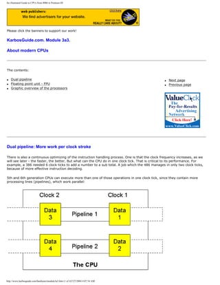
![An illustrated Guide to CPUs from 8086 to Pentium-III
Please also read the section about MMX, about 3DNow!, and Katmai instructions.
Floating point unit - FPU
[top]
The first CPUs could only work with whole numbers. Therefore, it was necessary to add a mathematical co-processor
(FPU), when better math power was needed. Later, this FPU was built into the CPU:
CPU FPU
8086 8087
80286 80287
80386 80387
80486DX Built in
80486SX None
Pentium and thereafter Built in
It is said that Intel's CPUs have by far the best FPU units. Processors from AMD and Cyrix definitely have a reputation for
providing sub standard performance in this area. But, you may not utilize the FPU. That depends on the applications (user
programs) you are using. Common office programs do not use the floating point operations, which the FPU can handle.
However, 3D graphics programs like AutoCad do. And all 3D-games like Quake rely heavily on FPU perfomance! Read
more of this subject here.
Therefore, if you use your PC in advanced design applications, the FPU performance becomes significant. For some users,
it is only of limited importance.
Graphic overview of the processors
[top]
There are CPUs of many brand names (IBM, Texas, Cyrix, AMD), and often they make models which overlap two
generations. This can make it difficult to keep of track of CPUs. Here is an attempt to identify the various CPUs according
to generation:
http://www.karbosguide.com/hardware/module3a3.htm (2 of 4)7/27/2004 4:07:54 AM](https://image.slidesharecdn.com/computerrepair-acompleteillustratedguidetopchardware-140318001250-phpapp01/85/Computer-repair-_a_complete_illustrated_guide_to_pc_hardware-322-320.jpg)
![An illustrated Guide to CPUs from 8086 to Pentium-III
q Next page
q Previous page
Learn more [top]
http://www.karbosguide.com/hardware/module3a3.htm (3 of 4)7/27/2004 4:07:54 AM](https://image.slidesharecdn.com/computerrepair-acompleteillustratedguidetopchardware-140318001250-phpapp01/85/Computer-repair-_a_complete_illustrated_guide_to_pc_hardware-323-320.jpg)
![An illustrated Guide to CPUs from 8086 to Pentium-III
Click for Module 3c about the 5th generations CPUs (Pentiums etc.)
Click for Module 3d about the clock frequencies
Click for Module 3e about 6th generations CPUs (Pentium IIs etc.)
[Main page] [Contact] [Karbo's Dictionary] [The Software Guides]
Copyright (c) 1996-2001 by Michael B. Karbo. www.karbosguide.com.
http://www.karbosguide.com/hardware/module3a3.htm (4 of 4)7/27/2004 4:07:54 AM](https://image.slidesharecdn.com/computerrepair-acompleteillustratedguidetopchardware-140318001250-phpapp01/85/Computer-repair-_a_complete_illustrated_guide_to_pc_hardware-324-320.jpg)
![An illustrated Guide to CPU improvements
Clock frequency
[top]
We know this from the ads: "A Celeron 466 MHz." The 466 MHz is the clock frequency.
Actually, there is a small crystal on the motherboard. which continually ticks to the CPU at a
steady number of clock ticks per second. At each clock tick something happens in the CPU.
Thus, the more ticks per second – the more data are processed per second.
The first CPUs worked at a frequency of 4.77 MHz. Subsequently then, clock frequencies rates
rose to 16, 25, 50, 66, 90, 133 and 200 MHz to the best today, which operate at almost 2000
MHz. Clock frequencies are still being increased. In a few years we will have CPUs operating
at 3 GHz and more.
To reach these very high clock frequencies, one has to employ a technique called clock
doubling.
Clock doubling in the CPU
[top]
The problem with the high clock frequencies is to ensure that other electronic components
keep up with the pace. It is rather simple to make data move very fast inside a chip where
the print tracks are microscopic. But when we move outside the chip, other problems appear.
The other components must be able to keep up with the pace. When the frequency gets too
high, the circuit board print tracks start acting as antennae and various forms of "radio noise"
appears. Briefly, it becomes expensive to make the rest of the hardware to keep up with
these high frequencies.
The solution to this problem was to split the clock frequency in two:
q A high internal clock frequency, which governs the pace of the CPU.
q A lower external clock frequency, which governs the pace on the system bus.
http://www.karbosguide.com/hardware/module3b1.htm (2 of 4)7/27/2004 4:07:56 AM](https://image.slidesharecdn.com/computerrepair-acompleteillustratedguidetopchardware-140318001250-phpapp01/85/Computer-repair-_a_complete_illustrated_guide_to_pc_hardware-326-320.jpg)
![An illustrated Guide to CPU improvements
Intel's 80486DX2 25/50 MHz was the first chip with clock doubling. It was introduced in 1992
with great potential. For a lower price you could acquire a chip, which provided 90% of the
486DX50 performance. The DX50 ran at 50 MHz both internally and externally. The DX2 ran
at just 25 MHz on the system bus. This enabled lower cost motherboards. Also RAM speed
demands were lower.
Clock doubling occurs inside the CPU. If the motherboard crystal works at 25 MHz, the CPU
will receive a signal every 40 nanosecond (ns). Internally in the CPU, this frequency is
doubled to 50 MHz. Now the clock ticks every 20 ns inside the CPU. This frequency governs
all internal transactions, including integer unit, floating point unit, and all memory
management unit operations as well as others. The only area still working at 25 MHz are
external data transfers. That is transfers to RAM, BIOS and the I/O ports.
RAM speeds
The speed of the CPU is also connected to the RAM. The ordinary FPM RAM and EDO RAM can
functioned at a maximum of 66 MHz (possibly 75 MHz). Therefore, Pentium and similar CPUs
were "clocked up" with factors from 2 to 5 internally.
In 1998 the PC100 RAM was introduced together with new motherboards and chip set. This
RAM works at 100 MHz, and using the clock factors 3.5, 4 and 4.5 we had CPUs running at
350, 400 and 450 MHz. The Intel CPUs Pentium II, Celeron, and Pentium III can operate with
clock factors of up to 8.
With chip set designs like i815 the internal clock frequency operates independently of the FSB
(front side bus) connecting the CPU to the north bridge of the chip set. Hence we do not need
to talk about clock doubling anymore, and the clock frequencies of the CPU reaches 1700
MHz and above.
q Next page
q Previous page
Learn more [top]
Also see Module 3c about the 5th generations CPUs (Pentiums etc.)
Click for Module 3d about the clock frequencies
Click for Module 3e about 6th generations CPUs (Pentium IIs etc.)
http://www.karbosguide.com/hardware/module3b1.htm (3 of 4)7/27/2004 4:07:56 AM](https://image.slidesharecdn.com/computerrepair-acompleteillustratedguidetopchardware-140318001250-phpapp01/85/Computer-repair-_a_complete_illustrated_guide_to_pc_hardware-327-320.jpg)
![An illustrated Guide to CPU improvements
[Main page] [Contact] [Karbo's Dictionary] [The Software Guides]
Copyright (c) 1996-2001 by Michael B. Karbo. www.karbosguide.com.
http://www.karbosguide.com/hardware/module3b1.htm (4 of 4)7/27/2004 4:07:56 AM](https://image.slidesharecdn.com/computerrepair-acompleteillustratedguidetopchardware-140318001250-phpapp01/85/Computer-repair-_a_complete_illustrated_guide_to_pc_hardware-328-320.jpg)
![An illustrated Guide to CPU improvements
Please click the banners to support our work!
KarbosGuide.com. Module 3b2.
The CPU – developments and improvements
The contents:
q Cache RAM
q Cache overview
q Next page
q Previous page
Please support our
sponsor.
About CPU cache RAM
[top]
The CPU must deliver its data at a very high speed. The regular RAM cannot keep up with
that speed. Therefore, a special RAM type called cache is used as a buffer - temporary
storage. To get top performance from the CPU, the number of outgoing transactions must be
minimized. The more data transmissions, which can be contained inside the CPU, the better
the performance. Therefore, the Intel 80486 was equipped with a built in mathematical co-
processor, floating point unit and 8 KB L1-cache RAM. These two features help minimize the
data flow in and out of the CPU.
http://www.karbosguide.com/hardware/module3b2.htm (1 of 4)7/27/2004 4:07:57 AM](https://image.slidesharecdn.com/computerrepair-acompleteillustratedguidetopchardware-140318001250-phpapp01/85/Computer-repair-_a_complete_illustrated_guide_to_pc_hardware-329-320.jpg)
![An illustrated Guide to CPU improvements
Cache RAM becomes especially important in clock doubled CPUs, where internal clock
frequency is much higher than external. Then the cache RAM enhances the "horsepower" of
the CPU, by allowing faster receipt or delivery of data. Beginning with 486 processors, two
layers of cache are employed. The fastest cache RAM is inside the CPU. It is called L1 cache.
The next layer is the L2 cache, which are small SRAM chips on the motherboard. See the
illustration below of a traditional Pentium PC:
How much RAM
The L2 cache can cache a certain amount of RAM. How much is determined by the chip set
and the so-called TAG-RAM, the circuit controlling the cache.
One of the most popular chip sets for the original Pentium was Intel´s 82430TX. it worked
very well - except for detail. it could not cache more than 64 MB RAM. If you added more
RAM to the PC, it was not cached by the L2 cache. Hence, using more than 64 MB of RAM on
a TX-based motherboard decreased the performance.
This situation has caused a lot of rumors about Windows not being able to use more than 64
MB RAM. However: Windows 98 can use up to 2 GB RAM! The only problems with the amount
of RAM has come from poorly designed chip sets as the TX.
Cache overview
[top]
L1-cache first appeared in Intel's 80486DX chip. Today, bigger and better CPU cache is a
natural step in the development of new CPUs. Here we only see the internal caches, i.e.
http://www.karbosguide.com/hardware/module3b2.htm (2 of 4)7/27/2004 4:07:57 AM](https://image.slidesharecdn.com/computerrepair-acompleteillustratedguidetopchardware-140318001250-phpapp01/85/Computer-repair-_a_complete_illustrated_guide_to_pc_hardware-330-320.jpg)
![An illustrated Guide to CPU improvements
cache integrated to the CPU and working at the full clock speed.
CPU Cache size in the CPU
80486DX and DX2 8 KB L1
80486DX4 16 KB L1
Pentium 16 KB L1
Pentium Pro 16 KB L1 + 256 KB L2
(some 512 KB L2)
Pentium MMX 32 KB L1
AMD K6 and K6-2 64 KB L1
Pentium II and III 32 KB L1
Celeron 32 KB L1 + 128 KB L2
Pentium III Cumine 32 KB L1 + 256 KB L2
AMD K6-3 64 KB L1 + 256 KB L2
AMD K7 Athlon 128 KB L1
AMD Duron 128 KB L1 + 64 KB L2
AMD Athlon Thunderbird 128 KB L1 + 256 KB L2
q Next page
q Previous page
Learn more [top]
http://www.karbosguide.com/hardware/module3b2.htm (3 of 4)7/27/2004 4:07:57 AM](https://image.slidesharecdn.com/computerrepair-acompleteillustratedguidetopchardware-140318001250-phpapp01/85/Computer-repair-_a_complete_illustrated_guide_to_pc_hardware-331-320.jpg)
![An illustrated Guide to CPU improvements
Also see Module 3c about the 5th generations CPUs (Pentiums etc.)
Click for Module 3d about the clock frequencies
Click for Module 3e about 6th generations CPUs (Pentium IIs etc.)
[Main page] [Contact] [Karbo's Dictionary] [The Software Guides]
Copyright (c) 1996-2001 by Michael B. Karbo. www.karbosguide.com.
http://www.karbosguide.com/hardware/module3b2.htm (4 of 4)7/27/2004 4:07:57 AM](https://image.slidesharecdn.com/computerrepair-acompleteillustratedguidetopchardware-140318001250-phpapp01/85/Computer-repair-_a_complete_illustrated_guide_to_pc_hardware-332-320.jpg)
![An illustrated Guide to CPU improvements
KarbosGuide.com. Module 3b3.
The CPU – developments and improvements
The contents:
q Areas of development
q The CPU – speed measurement
q CPU changes - historical review
q 80486DX4
q Next page
q Previous page
Please support our
sponsor.
Areas of development
[top]
In the following table, you see some of the technologies, which can be improved in the CPU
design. Note that internal means inside the CPU. External speed, etc. refers to features
http://www.karbosguide.com/hardware/module3b3.htm (1 of 6)7/27/2004 4:07:59 AM](https://image.slidesharecdn.com/computerrepair-acompleteillustratedguidetopchardware-140318001250-phpapp01/85/Computer-repair-_a_complete_illustrated_guide_to_pc_hardware-333-320.jpg)
![An illustrated Guide to CPU improvements
immediately outside the CPU – on the motherboard.
Development area Significance Example
Internal clock frequency speed of data processing inside
the CPU.
800 MHz
External clock frequency Speed of data transfer to and
from the CPU via the system bus
(or Front Side Bus).
133 MHz
Clock doubling That the CPU works x times
faster internally than externally.
6.0 times (like above)
Internal data width How many data bits can the CPU
process simultaneously.
32 bits
External data width How many data bits can the CPU
receive simultaneously for
processing
64 bits
Internal cache (Level 1 cache) Large and better L1 cache, which
is a small fast RAM. It works as a
buffer between CPU and regular
RAM.
64 KB
External cache (Level 2
cache)
Larger and better implemented
L2 cache, place on-die in same
chip as CPU.
256 or 512 KB
Instruction set Can the instruction set be
simplified, to speed up program
processing? Or can it be
improved?
RISC code
More pipelines
MMX instructions
3DNow! or SSE
The CPU – speed measurement
[top]
When we look at a CPU, its speed is the most significant feature. All newer CPUs can do the
same. You can run Office 2000 in Windows 98 on a 486 CPU. It would be quite slow, but it is
possible.
Speed is the primary difference between newer CPUs. Speed improvement is a product of the
above mentioned technologies (such as clock frequency and bus width).
The old Speed Index
http://www.karbosguide.com/hardware/module3b3.htm (2 of 6)7/27/2004 4:07:59 AM](https://image.slidesharecdn.com/computerrepair-acompleteillustratedguidetopchardware-140318001250-phpapp01/85/Computer-repair-_a_complete_illustrated_guide_to_pc_hardware-334-320.jpg)
![An illustrated Guide to CPU improvements
There are many, many ways to measure CPU speed. The subject is boundless. For years,
Norton's Speed Index was used. That is a test, which can be run on any PC with the Norton
Utilities Sysinfo program.
In the table below, you see a number of the most common older CPUs. You can see how they
are designed regarding clock speed and bus width. The last column shows their Norton Speed
Index (SI). That is a relative number, which can be used to compare different CPUs. It is not
used for modern CPUs.
CPU CPU speed Clock
doubling
System bus
speed
Data width SI
8086 4.77 MHz 1 4.77 MHz 16 bit 1
80286 12 MHz 1 12 MHz 16 bit 8
80386DX 25 MHz 1 25 MHz 32 bit 40
486 DX2-66 66 MHz 2 33 MHz 32 bit 142
5x86-133 133 MHz 4 33 MHz 32 bit 288
Pentium 75 75 MHz 1.5 50 MHz 64 bit 235
Pentium 90 90 MHz 1.5 60 MHz 64 bit 278
Pentium 100 100 MHz 1.5 66 MHz 64 bit 305
Pentium 133 133 MHz 2 66 MHz 64 bit 420
Pentium 166 166 MHz 2.5 66 MHz 64 bit 527
Pentium 200 200 MHz 3 66 MHz 64 bit 629
Newer CPUs are compared by their clock frequency or by more more sophisticated ratings.
CPU changes - historical review
[top]
This describes briefly the changes throughout the early CPU generations:
8088 and 8086
The 8086 from 1978 was the first 16 bit CPU from Intel using a 16 bit system bus. However
16 bit hardware such as motherboards were too expensive and even non existing at this
time, where the 8 bit microcomputers were the standard.
In 1979 Intel reengineered the CPU so it fit with existing 8 bit hardware. The first PC (in
1981) had this 8088 CPU. The 8088 is a 16 bit CPU, but only internally. The external data bus
width is only 8 bit giving compatibility with existing hardware.
http://www.karbosguide.com/hardware/module3b3.htm (3 of 6)7/27/2004 4:07:59 AM](https://image.slidesharecdn.com/computerrepair-acompleteillustratedguidetopchardware-140318001250-phpapp01/85/Computer-repair-_a_complete_illustrated_guide_to_pc_hardware-335-320.jpg)
![An illustrated Guide to CPU improvements
its predecessor - all things being equal. That is because of better implementation of the x86
instructions. They are handled faster, more in RISC mode. At the same time bus speed is
increased, but both 386DX and 486DX are 32 bit chips. A novelty in the 486 is the built in
math co-processor. Before, that had to be installed as a separate 387 chip. The 486 also held
8 KB of L1 cache.
80486SX
This was a new discount chip. The math co-processor was simply omitted.
Cyrix 486SLC: Cyrix and Texas Instruments have made a series of 486SLC chips. They used
the same set of instructions as did the 486DX, and they run at 32 bit internally, like the DX.
However, externally they run at only 16 bit (like a 386SX). Therefore, they can only handle
16 MB RAM. Furthermore, they only have 1 KB internal cache and no mathematical co-
processor. Actually they are just improved 286/386SXs. They are not cloned chips. There are
substantial differences in their architecture compared to the Intel chips.
IBM 486SLC2: IBM had their own 486 chip production. The series was named SLC2 and
SLC3. The latter was also known as Blue Lightning. These chips could be compared to Intel's
486SX, since they did not have a built-in mathematical co-processor. However, they had 16
KB internal cache (compared to Intel's 8). What reduced their performance was the bus
interface, which was from the 386 chip. SLC2 runs at 25/50 MHz externally and internally,
while the SLC3 chip runs at 25/75 and 33/100 MHz. IBM manufactured these chips for their
own PCs in their own facilities, licensing the logic from Intel. The chips were not sold
separately.
DX4: Further 486 developments
[top]
Intel's DX4 processors represented an improvement on the 80486 series. The clock speed
was tripled from 25 to 75 MHz and from 33 to 100 MHz. Another DX4 chip was speeded up
from 25 to 83 MHz.
Contrary to what you might think, the DX4 were not named for a quadrupling. They were
named this way because of the registry of Intel's 80486 and 80586 names. The DX4 name is
separated from that context, so it could be patented. If DX3 referred to a tripling, this would
not work. The same type of problem caused the next generation chip to be named Pentium,
rather than 80586.
The DX4 has 16 KB internal cache and operates on 3.3 volt (they will tolerate 5 volt, to
accommodate existing system boards). DX and DX2 have only 8 KB cache and require 5 volt
with inherent heat problems.
5X86: AMD has made a series of so called 5X86 CPUs. Those are improved 486s, which
approach the 5th generation chips, hence their name. Their 120 MHz model is noteworthy. It
could easily be tuned to run at 160 MHz.
http://www.karbosguide.com/hardware/module3b3.htm (5 of 6)7/27/2004 4:07:59 AM](https://image.slidesharecdn.com/computerrepair-acompleteillustratedguidetopchardware-140318001250-phpapp01/85/Computer-repair-_a_complete_illustrated_guide_to_pc_hardware-337-320.jpg)
![An illustrated Guide to CPU improvements
q Next page
q Previous page
Learn more [top]
Click for Module 3d about the clock frequencies
Click for Module 3e about 6th generations CPUs (Pentium IIs etc.)
[Main page] [Contact] [Karbo's Dictionary] [The Software Guides]
Copyright (c) 1996-2001 by Michael B. Karbo. www.karbosguide.com.
http://www.karbosguide.com/hardware/module3b3.htm (6 of 6)7/27/2004 4:07:59 AM](https://image.slidesharecdn.com/computerrepair-acompleteillustratedguidetopchardware-140318001250-phpapp01/85/Computer-repair-_a_complete_illustrated_guide_to_pc_hardware-338-320.jpg)
![An illustrated Guide to Pentiums
Please click the banners to support our work!
KarbosGuide.com. .
Module 3c. About the 5th generations CPUs
With Intel's Pentium from 1993, a new era began in the continued CPU development. In these pages, we will look
at different variations and further development of 5th. generation CPUs.
q The original Pentium q Next page
q Previous page
Please support our
sponsor.
Pentium Classic (P54C)
[top]
This chip was developed by Intel in Haifa, Israel and was released on March the 22th 1993.
http://www.karbosguide.com/hardware/module3c1.htm (1 of 3)7/27/2004 4:08:01 AM](https://image.slidesharecdn.com/computerrepair-acompleteillustratedguidetopchardware-140318001250-phpapp01/85/Computer-repair-_a_complete_illustrated_guide_to_pc_hardware-339-320.jpg)
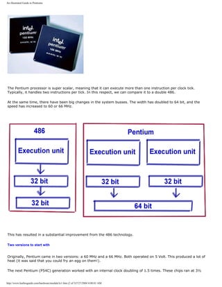
![An illustrated Guide to Pentiums
Volt. This took care of the heat problem. However, heat coming from the CPU has been a problem ever since.
With these the first P5 processors, Intel carried two Pentium lines; some running at 60 MHz on the system bus
(The P90, P120, P150, and P180) and others with 66 MHz system bus (the P100, P133, P166 and P200).
q Next page
q Previous page
Learn more [top]
Or continue with the 6th generation CPUs. Click for Module 3e.
Read module 5a about expansion cards, where we evaluate the I/O buses from the port side.
Read module 5b about AGP and module 5c about Firewire.
Read module 7a about monitors, and 7b on graphics card.
Read module 7c about sound cards, and 7d on digital sound and music.
[Main page] [Contact] [Karbo's Dictionary] [The Software Guides]
Copyright (c) 1996-2001 by Michael B. Karbo. www.karbosguide.com.
http://www.karbosguide.com/hardware/module3c1.htm (3 of 3)7/27/2004 4:08:01 AM](https://image.slidesharecdn.com/computerrepair-acompleteillustratedguidetopchardware-140318001250-phpapp01/85/Computer-repair-_a_complete_illustrated_guide_to_pc_hardware-341-320.jpg)
![An illustrated Guide to Pentiums
Please click the banners to support our work!
KarbosGuide.com. .
Module 3c2. About the 5th generations CPUs - continued
q The Cyrix 6x86
q The AMD K5
q Next page
q Previous page
Please support our
sponsor.
Cyrix [top]
This is a low cost alternative to Pentium. The chip from the Cyrix company, which was
introduced February 5, 1996, is a cheap Pentium copy.
http://www.karbosguide.com/hardware/module3c2.htm (1 of 5)7/27/2004 4:08:03 AM](https://image.slidesharecdn.com/computerrepair-acompleteillustratedguidetopchardware-140318001250-phpapp01/85/Computer-repair-_a_complete_illustrated_guide_to_pc_hardware-342-320.jpg)
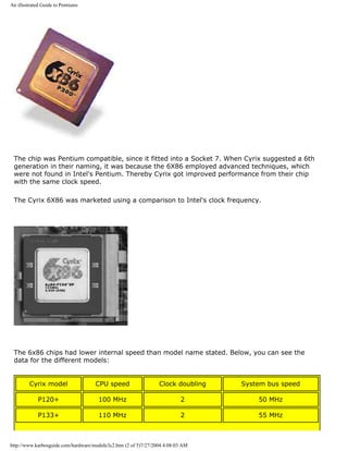
![An illustrated Guide to Pentiums
P166+ 133 MHz 2 66 MHz
P200+ 150 MHz 2 75 MHz
An interesting detail was, that the 6X86 P200+ was the first CPU to run a system bus speed
above 66 MHz. However it was difficult to find motherboards with chip sets capable of this, so
the chip never achieved an important position in the market.
Cyrix 6X86s were known for poor performance regarding floating point operations. There also
were problems with Cyrix and NT 4.0.
In my experience, the 6x86 did quite a good job with common office programs in Windows
95. I was very satisfied with the P166+ I had. Of course I would prefer a genuine Pentium
166, but I was not willing to pay three times the price at that time.
The 6X86 was later improved with Dual Voltage (like Pentium P55C). This reduced power
consumption and heat generation.
Also see the article on Cyrix M3. The company Cyrix was in 1999 taken over by Taiwanese
chip producer VIA.
[top]
AMD is another CPU brand, which has become very important. Their Pentium like chips
offered Intel tight competition. AMD used their own technologies, and hence they are not
clones. They had these series:
q K5, corresponding to the classic Pentiums (with 16 KB L1 cache and no MMX)
q K6, K6-2, and K6-3 which compete with Pentium MMX and Pentium II
q K7 Athlon, from August 1999, which is not Socket 7 compatible.
K5
K5 was Pentium copy. The old K5 was for example sold as PR133. This means, that the chip
should perform like a Pentium P133. However, it only runs 100 MHz internally. It still has to
be installed in the motherboard like a P133.
http://www.karbosguide.com/hardware/module3c2.htm (3 of 5)7/27/2004 4:08:03 AM](https://image.slidesharecdn.com/computerrepair-acompleteillustratedguidetopchardware-140318001250-phpapp01/85/Computer-repair-_a_complete_illustrated_guide_to_pc_hardware-344-320.jpg)
![An illustrated Guide to Pentiums
AMD's K5 also existed as PR166. As the name suggests, it was intended to compete with
Intel's P166. It operated at just 116.6 MHz internally (1.75 X 66 MHz). According to the
highly respected German magazine c't, issue 3.97 page 20, it actually ran at least as fast as
the P166.
This was due to an optimized cache and other new developments. The only feature on which
it could not match the P166 was in floating point operations. These are typically necessary in
3D calculations in AutoCAD and similar applications.
PR133 and PR166 cost far less than the similar Pentium models, and they were very popular
in low budget machines.
q Next page
q Previous page
Learn more [top]
Or continue with the 6th generation CPUs. Click for Module 3e.
Read module 5a about expansion cards, where we evaluate the I/O buses from the port side.
Read module 5b about AGP and module 5c about Firewire.
Read module 7a about monitors, and 7b on graphics card.
Read module 7c about sound cards, and 7d on digital sound and music.
http://www.karbosguide.com/hardware/module3c2.htm (4 of 5)7/27/2004 4:08:03 AM](https://image.slidesharecdn.com/computerrepair-acompleteillustratedguidetopchardware-140318001250-phpapp01/85/Computer-repair-_a_complete_illustrated_guide_to_pc_hardware-345-320.jpg)
![An illustrated Guide to Pentiums
[Main page] [Contact] [Karbo's Dictionary] [The Software Guides]
Copyright (c) 1996-2001 by Michael B. Karbo. www.karbosguide.com.
http://www.karbosguide.com/hardware/module3c2.htm (5 of 5)7/27/2004 4:08:03 AM](https://image.slidesharecdn.com/computerrepair-acompleteillustratedguidetopchardware-140318001250-phpapp01/85/Computer-repair-_a_complete_illustrated_guide_to_pc_hardware-346-320.jpg)
![An illustrated Guide to Pentiums
Please click the banners to support our work!
KarbosGuide.com. .
Module 3c3. The 5th generations CPUs - continued
q The P55C - MMX
q IDT WinChip
q Voltages - dual voltage
q Next page
q Previous page
Please support our
sponsor.
Pentium MMX (P55C)
[top]
The P55C Pentiums were introduced January 8, 1997. MMX is a new set of instructions (57
new integer instructions, four new data types, and eight 64 bit registers), which expand the
http://www.karbosguide.com/hardware/module3c3.htm (1 of 6)7/27/2004 4:08:06 AM](https://image.slidesharecdn.com/computerrepair-acompleteillustratedguidetopchardware-140318001250-phpapp01/85/Computer-repair-_a_complete_illustrated_guide_to_pc_hardware-347-320.jpg)
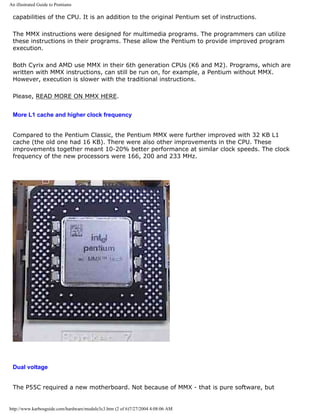
![An illustrated Guide to Pentiums
because of changes in the power supply. The P55C operated with dual voltage technology. To
reduce heat generation, this chip requires two different voltages: 2.8 Volt to the nucleus and
3.3 Volt to the I/O section. The old motherboards for the P54Cs have only one voltage to the
CPU. Thus, the new CPU requires a new motherboard.
Tillamook
For use in laptops Intel has a special power-saving version of the Pentium MMX. The so-called
Tillamook processor is manufactured using 0.25 micron technology, and you find it in 266
and 300 MHz versions.
IDT Winchip
[top]
IDT was another smaller company to produce low-priced Pentium MMX-like CPUs. Their first
WinChip C6 was introduced in May 1997. The company wanted to deliver 200 MHz Pentium
MMXs for $50.
http://www.karbosguide.com/hardware/module3c3.htm (3 of 6)7/27/2004 4:08:06 AM](https://image.slidesharecdn.com/computerrepair-acompleteillustratedguidetopchardware-140318001250-phpapp01/85/Computer-repair-_a_complete_illustrated_guide_to_pc_hardware-349-320.jpg)
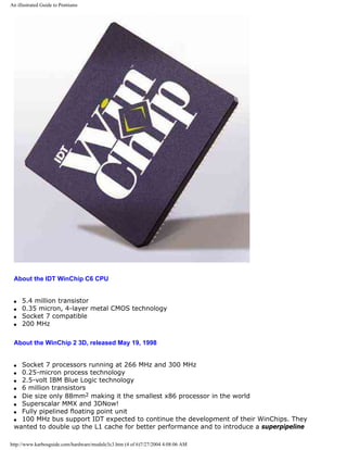
![An illustrated Guide to Pentiums
technology, which also will speed up the whole thing.
We never saw many IDT chips in my country.
In 1999 the company was taken over by VIA who integrates the IDT technology in their Cyrix
processor line.
Voltages - dual voltage
[top]
One of the most important CPU technologies is the continually thinner wires inside the chip.
With thinner wires, the CPU can operate at lower voltage. That results in a smaller CPU
generating less heat and with the ability to operate at higher speeds. A step in this
development is the design of dual voltage chips:
q The interface to the I/O bus, which always requires 3.3 volt.
q In internal CPU parts, it is advantageous to reduce the voltage as much as possible. This
can be done because of the extremely thin wires in the CPU. The Socket 7 motherboards
have a two part voltage regulator to match the needs of the CPU. Here are some selected
CPUs and their voltage requirements:
CPU Internal voltage I/O voltage
Pentium MMX 2.8 Volt 3.3 Volt
AMD K6 2.8/2.9 Volt 3.3 Volt
Cyrix 6X86MX 2.8 Volt 3.3 Volt
Pentium II "Klamath" 2.8 Volt 3.3 Volt
AMD K6-2 2.2 Volt 3.3 Volt
Pentium II and III 2.0 Volt 3.3 Volt
Pentium III "CuMine" 1.6 Volt 3.3 Volt
q Next page
q Previous page
http://www.karbosguide.com/hardware/module3c3.htm (5 of 6)7/27/2004 4:08:06 AM](https://image.slidesharecdn.com/computerrepair-acompleteillustratedguidetopchardware-140318001250-phpapp01/85/Computer-repair-_a_complete_illustrated_guide_to_pc_hardware-351-320.jpg)
![An illustrated Guide to Pentiums
Learn more [top]
Or continue with the 6th generation CPUs. Click for Module 3e.
Read module 5a about expansion cards, where we evaluate the I/O buses from the port side.
Read module 5b about AGP and module 5c about Firewire.
Read module 7a about monitors, and 7b on graphics card.
Read module 7c about sound cards, and 7d on digital sound and music.
[Main page] [Contact] [Karbo's Dictionary] [The Software Guides]
Copyright (c) 1996-2001 by Michael B. Karbo. www.karbosguide.com.
http://www.karbosguide.com/hardware/module3c3.htm (6 of 6)7/27/2004 4:08:06 AM](https://image.slidesharecdn.com/computerrepair-acompleteillustratedguidetopchardware-140318001250-phpapp01/85/Computer-repair-_a_complete_illustrated_guide_to_pc_hardware-352-320.jpg)
![An illustrated Guide to Pentiums
Please click the banners to support our work!
www.karbosguide.com
Module 3c4. The 5th generations CPUs - continued
q Chip production
q Moore's Law
q Various notes about CPUs
q Next page
q Previous page
Please support our
sponsor.
Chip production
[top]
It takes a long time to manufacture a CPU. 5 to 50 million transistors must be placed on a
tiny silicon wafer. Actually, it required 90 workdays 24 hours round-the-clock to produce a
Pentium CPU.
http://www.karbosguide.com/hardware/module3c4.htm (1 of 6)7/27/2004 4:08:08 AM](https://image.slidesharecdn.com/computerrepair-acompleteillustratedguidetopchardware-140318001250-phpapp01/85/Computer-repair-_a_complete_illustrated_guide_to_pc_hardware-353-320.jpg)
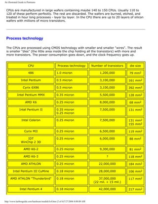
![An illustrated Guide to Pentiums
Intel Pentium 4 Northwood 0.13 micron 42,000,000 116 mm2
Athlon T 0.13 micron 37,000,000 80 mm2
Here you see the Intel process generations:
Process generation Year Gate length
P648 1989 1.0 micron
P650 1991 0.8 micron
P852 1993 0.5 micron
P854 1995 0.35 micron
P856 1997 0.25 micron
P858 2000 0.18/0.13 micron
Moore's Law
The CPUs have doubled their calculating capacity every 18 months. This is called "Moore's
Law" and was predicted in 1965 by Gordon Moore. He was right for more than 30 years. The
latest CPUs use internal wiring only 0.25 microns wide (1/400 of a human hair). But if
Moore's Law has to be valid into the next century, more transistors have to be squeezed onto
silicon layers.
IBM succeeded as the first in making copper conductors instead of aluminum. Copper is
cheaper and faster, but the problem was to isolate it from the silicon. The problem has been
solved with a new type of coating, and now chips can be designed with 0.13 micron
technology. The technology is expected later to work with just 0.05 micron wiring!
Texas Instruments announced on August 27th 1998 that they expect 0.07 micron CMOS
processing in the year 2001.
AMD was the first company to mass-produce copper-wired CPU's. This happened in their fab
30 in Dresden, April 2000.
Chip errors
[top]
The following miscalculations occur in 386, 486, and Pentium, when running Excel, Works, or
http://www.karbosguide.com/hardware/module3c4.htm (3 of 6)7/27/2004 4:08:08 AM](https://image.slidesharecdn.com/computerrepair-acompleteillustratedguidetopchardware-140318001250-phpapp01/85/Computer-repair-_a_complete_illustrated_guide_to_pc_hardware-355-320.jpg)
![An illustrated Guide to Pentiums
Pascal, with the numbers 49 and 187:
All CPUs have faulty instructions. Recently flaws have been discovered within the Pentium II
and Cyrix 6x86MX.
The Pentium scandal
[top]
Pentium was hit by a scandal in late 1994, when an error in the mathematical co-processor
(FPU) became publicly known. It simply miscalculated at a given division. Intel knew of the
error from early that summer but more or less kept it secret.
Intel insisted that the error would occur extremely rarely. Compaq immediately modified their
production to disable the FPU. Shortly thereafter, IBM announced that they would stop the
production of Pentium based PCs. IBM had calculated that the error would occur every 24
days. At the time, IBM was working to extricate themselves from the Intel CPU monopoly.
They were moving towards Power PC, Cyrix, and NexGen based PCs. Thus the scandal played
right into their hands. You see the error here, where A3 should be equal to A1:
Intel underestimated the significance of the miscalculations, certainly regarding users
employing complex mathematical calculations. IBM over dramatized the error for political
reasons. This all happened in December 1994, while Intel was running their big TV campaign
for Pentium.
That gave birth to a number of jokes: How many Pentium programmers are needed to screw
in a bulb? (answer: 1.9990427). Why is Pentium not named 586? Because it would have to
be called 585.999983405! In a different vein: How many Apple employees does it require to
change a bulb? 7! One to hold the bulb and 6 to design T-shirts. And: how many IBM
http://www.karbosguide.com/hardware/module3c4.htm (4 of 6)7/27/2004 4:08:08 AM](https://image.slidesharecdn.com/computerrepair-acompleteillustratedguidetopchardware-140318001250-phpapp01/85/Computer-repair-_a_complete_illustrated_guide_to_pc_hardware-356-320.jpg)
![An illustrated Guide to Pentiums
employees does it require to change a bulb? None! IBM simply announces a new feature
called "black bulb."
Intel Owner's Club site
[top]
This site is good if you are interested in the CPUs. Find the Intel Owner's Club, which is a
free, easy way for members to:
q get the scoop on the latest Intel technologies
q get info on hot new software and technologies
q interact with Intel & technology experts
q download free software and games
q enter contests.
My membership has helped me to learn how to use the Intel web site, which holds a lot of
information. Only Intel's servers can be terrible slow, so you easily get tired from them.
q Next page
q Previous page
Learn more [top]
Or continue with the 6th generation CPUs. Click for Module 3e.
Read module 5a about expansion cards, where we evaluate the I/O buses from the port
side.
Read module 5b about AGP and module 5c about Firewire.
Read module 7a about monitors, and 7b on graphics card.
Read module 7c about sound cards, and 7d on digital sound and music.
[Main page] [Contact] [Karbo's Dictionary] [The Software Guides]
http://www.karbosguide.com/hardware/module3c4.htm (5 of 6)7/27/2004 4:08:08 AM](https://image.slidesharecdn.com/computerrepair-acompleteillustratedguidetopchardware-140318001250-phpapp01/85/Computer-repair-_a_complete_illustrated_guide_to_pc_hardware-357-320.jpg)
![An illustrated Guide to Over-clocking.
Please click the banners to support our work!
KarbosGuide.com.
Module 3d.1 About Cooling and Over clocking
The contents:
q About cooling
q A clean cooler..
q Next page
q Previous page
Cooling
[top]
All modern CPUs share a common need for cooling. Make sure to include a good cooler. It has to be matched to
the size of the CPU.
q It has to be attached properly, either with glue or a clamp, which fits the CPU.
q It must have a substantial size heat sink - the bigger the better.
q The fan must be mounted in roller bearings, to minimize noise.
The bigger the fan and heat sink, the better it is. The CPU will operate more reliably. It will have a longer life
span, and it can possibly be over clocked. If you buy Intel CPUs, buy them "in a box". It is a special package,
priced slightly higher than just the CPU. They always include a good fan and a three year warranty.
http://www.karbosguide.com/hardware/module3d1.htm (1 of 7)7/27/2004 4:08:10 AM](https://image.slidesharecdn.com/computerrepair-acompleteillustratedguidetopchardware-140318001250-phpapp01/85/Computer-repair-_a_complete_illustrated_guide_to_pc_hardware-359-320.jpg)
![An illustrated Guide to Over-clocking.
Pentium with fan. Photo taken with Canon Powershot 600. JPG-file 1:30, 32 KB.
What is a cooler?
[top]
A cooler consists of two parts:
q A fan that needs power supply.
q A cooling element, usually made of metal ribs. The fan is placed on the top of the cooling element, which is
fastened very tight to the top of the CPU:
http://www.karbosguide.com/hardware/module3d1.htm (2 of 7)7/27/2004 4:08:10 AM](https://image.slidesharecdn.com/computerrepair-acompleteillustratedguidetopchardware-140318001250-phpapp01/85/Computer-repair-_a_complete_illustrated_guide_to_pc_hardware-360-320.jpg)
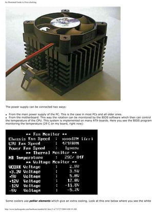
![An illustrated Guide to Over-clocking.
peltier-thing at the bottom. Notice the two-fold power supply:
Cleaning the cooler
[top]
Another important thing to take care of is vacuum cleaning the fan on a regular basis. My old Pentium Pro has
a very big fan on it. It began giving error messages within Windows . I really could not find out why. Until I
discovered that the heating sink was extremely hot. The fan was rotating as it should, but a large amount of
dust had gathered just beneath it, so the air did not cool the sink at all!
http://www.karbosguide.com/hardware/module3d1.htm (4 of 7)7/27/2004 4:08:10 AM](https://image.slidesharecdn.com/computerrepair-acompleteillustratedguidetopchardware-140318001250-phpapp01/85/Computer-repair-_a_complete_illustrated_guide_to_pc_hardware-362-320.jpg)
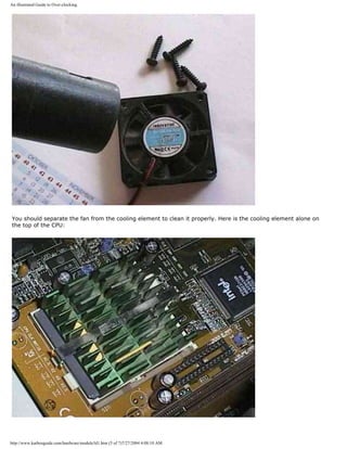
![An illustrated Guide to Over-clocking.
What to be learned: Check your CPU fan once a year. Perhaps you have to disconnect the CPU to clean it
thoroughly. Take the CPU in your hand and hold the vacuum cleaner close to the sink.
Here you see a powerful cooling device for (over clocking) Pentium IIs. It contains three fans (the third being
difficult to see, it's in the middle of the device) plus a peltier element:
q Next page
q Previous page
Learn more
[top]
Read Module 3e - about the latest CPUs.
Read more about the boot process and system bus in Module 2b
http://www.karbosguide.com/hardware/module3d1.htm (6 of 7)7/27/2004 4:08:10 AM](https://image.slidesharecdn.com/computerrepair-acompleteillustratedguidetopchardware-140318001250-phpapp01/85/Computer-repair-_a_complete_illustrated_guide_to_pc_hardware-364-320.jpg)
![An illustrated Guide to Over-clocking.
Read more about I/O buses in module 2c
Read more about the chip sets in module 2d
Read more about RAM in module 2e
Read about EIDE in module 5b
[Main page] [Contact] [Karbo's Dictionary] [The Software Guides]
Copyright (c) 1996-2001 by Michael B. Karbo. www.karbosguide.com.
http://www.karbosguide.com/hardware/module3d1.htm (7 of 7)7/27/2004 4:08:10 AM](https://image.slidesharecdn.com/computerrepair-acompleteillustratedguidetopchardware-140318001250-phpapp01/85/Computer-repair-_a_complete_illustrated_guide_to_pc_hardware-365-320.jpg)
![An illustrated Guide to Over-clocking.
Please click the banners to support our work!
KarbosGuide.com. Module 3d.2
About Cooling and Over clocking (continued)
The contents:
q What is clocking?
q Two frequencies to clock on..
q What is over clocking?
q Next page
q Previous page
Please support our
sponsor.
What is clocking?
[top]
All Pentium CPUs run with clock doubling. That's the way they are built. The PC works with two
frequencies, which the user can adjust. The clock doubling is set on small jumpers on the
motherboard. You simply set a clock doubling factor, to make the CPU work – but who says that
you must use the factor listed in the manual?
If you are brave, you try to set your CPU to run faster than it is designed to run. Often it works. If
you "cheat" the CPU in this manner to work faster, it is called over clocking. Over clocking is kind
of a PC tuning, which can be fun to fool with – if you are interested in the technicalities of PC-
hardware. Otherwise - skip it!.
http://www.karbosguide.com/hardware/module3d2.htm (1 of 8)7/27/2004 4:08:13 AM](https://image.slidesharecdn.com/computerrepair-acompleteillustratedguidetopchardware-140318001250-phpapp01/85/Computer-repair-_a_complete_illustrated_guide_to_pc_hardware-366-320.jpg)
![An illustrated Guide to Over-clocking.
If you are lucky, you can make a medium speed CPU run as fast as the top of the line version!
Please note, I accept no responsibility for the result of your experiments. I will now try to explain
the technologies in the over clocking phenomenon. The interesting part is that, like much of the
theory I tried to describe in in the modules 3a, 3 b and 3c, it all comes together here in the clock
doubling technology.
Two frequencies to clock
[top]
The CPU works on two frequencies: An internal and an external.
q The external clock frequency (the bus frequency) is the speed between the CPU and RAM. In the
Pentium CPUs it is actually the speed between L1 and L2 cache. In the Pentium II it is the speed
between L2 cache and RAM.
q The internal clock frequency is the speed inside the CPU, that is between L1 cache and the
various CPU registers.
For practical reasons you let these two frequencies depend on each other. In practice you choose a
given bus frequency (between 60 and 153 MHz) and double it up a number of times (between 3½
and 8). The latter frequency become the CPU internal work frequency.
Here I show a number of theoretical CPU frequencies, resulting form different clock doublings:
Many of these frequencies will actually never be used, but they are possible because of the system
structure:
Bus
frequencies
Clock
doubling
factors
Examples of resulting CPU frequencies
60 MHz
66 MHz
75 MHz
83 MHz
100 MHz
117 MHz
133 MHz
153 MHz
1½,
3½,
4,
4½,
5,
5½,
6
6½,
7
7½,
8
233 MHz, 266 MHz, 333 MHz
333 MHz, 366 MHz, 400 MHz,
433 MHz, 466 MHz, 500 MHz,
300 MHz, 338 MHz, 375 MHz,
375 MHz, 416 MHz, 458 MHz,
468 MHz, 527 MHz, 585 MHz
533 MHz, 600 MHz, 667 MHz,
612 MHz, 688 MHz, 765 MHz
Note an important point: The CPU frequency is the result of the the bus frequency multiplied with a
factor. If you increase the bus frequency, it affects the CPU frequency, which is also increased.
Look here at a page from the manual to a ASUS P2L97 motherboard. It has a clear instruction
about how to set the two values (bus frequency and clock factor). This (old) motherboard accepts
http://www.karbosguide.com/hardware/module3d2.htm (2 of 8)7/27/2004 4:08:13 AM](https://image.slidesharecdn.com/computerrepair-acompleteillustratedguidetopchardware-140318001250-phpapp01/85/Computer-repair-_a_complete_illustrated_guide_to_pc_hardware-367-320.jpg)
![An illustrated Guide to Over-clocking.
bus frequencies up to 83 MHz with a clock factor up to 5:
What is over clocking?
[top]
http://www.karbosguide.com/hardware/module3d2.htm (3 of 8)7/27/2004 4:08:13 AM](https://image.slidesharecdn.com/computerrepair-acompleteillustratedguidetopchardware-140318001250-phpapp01/85/Computer-repair-_a_complete_illustrated_guide_to_pc_hardware-368-320.jpg)
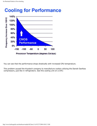
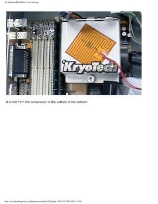
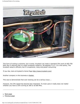
![An illustrated Guide to Over-clocking.
Learn more [top]
Also see Module 3e - about the latest CPUs.
Read more about the boot process and system bus in Module 2b
Read more about I/O buses in module 2c
Read more about the motherboard chip set in module 2d
Read more about RAM in module 2e
Read about EIDE in module 5b
[Main page] [Contact] [Karbo's Dictionary] [The Software Guides]
Copyright (c) 1996-2001 by Michael B. Karbo. www.karbosguide.com.
http://www.karbosguide.com/hardware/module3d2.htm (8 of 8)7/27/2004 4:08:13 AM](https://image.slidesharecdn.com/computerrepair-acompleteillustratedguidetopchardware-140318001250-phpapp01/85/Computer-repair-_a_complete_illustrated_guide_to_pc_hardware-373-320.jpg)
![An illustrated Guide to Over-clocking.
Please click the banners to support our work!
KarbosGuide.com. Module 3d.3
About Cooling and Over clocking (continued)
The contents:
q Which CPUs can be over clocked?
q Risks in over clocking?
q Next page
q Previous page
Please support our
sponsor.
Which CPUs can be over clocked?
[top]
The first CPUs which were dramatically over clocked were AMD's 5x86 series. That was a 486
http://www.karbosguide.com/hardware/module3d3.htm (1 of 5)7/27/2004 4:08:15 AM](https://image.slidesharecdn.com/computerrepair-acompleteillustratedguidetopchardware-140318001250-phpapp01/85/Computer-repair-_a_complete_illustrated_guide_to_pc_hardware-374-320.jpg)
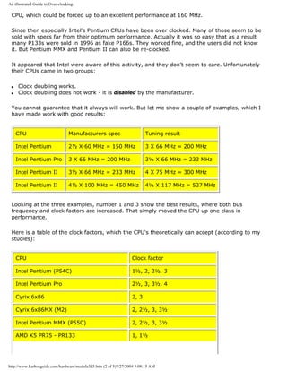
![An illustrated Guide to Over-clocking.
AMD K5 PR150 and PR166 2
AMD K6-2 and K6-3 4, 4½, 5
Intel Pentium II, Celeron and Pentium III Up to 8 and 12 (latest models)
Some AMD and Cyrix chips were special, in that they did not always respond to motherboard
settings. It is like they determined their own frequencies.
All modern Intel processors are locked at fixed clock factors (Multiplier Locking). They only
operate with one specific multiply factor.
The Celeron
The original Celeron was a Pentium II without L2 cache. This CPU was very overclocking
friendly. There are several reports about 300 MHz Celerons working at 504 MHz without any
problems at all.
The Celeron A
The Intel Celeron line starting with models 300A and 333 (both with 128 KB L2 cache on-
chip) are both protected against overclocking. They hold a "Multiplier Locking", which locks
them to the clockfactors 4.5 and 5.0 respectively.
The Celeron 533 will only work with clockfactor 8, so if you want to overclock it, you have to
go for a motherboard with adjustable system bus frequencies. This could be 8 X 100 MHz
instead of 8 X 66 MHz increasing the CPU speed from 533 MHz to 800 MHz. Many users have
found this in-expensive way to get a higher performance.
Disadvantages and risks in over-clocking?
[top]
Many factors need to be considered, when you start tampering with these system settings.
Watch out for:
q Heat. Can the CPU dissipate the heat?
q The L2 cache RAM of old Pentium II, III or Athlon cartridges - how fast can it work?
q RAM speed. Can it keep up with the system bus?
http://www.karbosguide.com/hardware/module3d3.htm (3 of 5)7/27/2004 4:08:15 AM](https://image.slidesharecdn.com/computerrepair-acompleteillustratedguidetopchardware-140318001250-phpapp01/85/Computer-repair-_a_complete_illustrated_guide_to_pc_hardware-376-320.jpg)
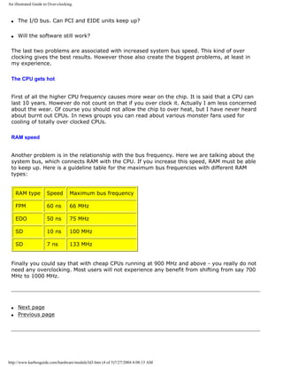
![An illustrated Guide to Over-clocking.
Learn more [top]
See Module 3e - about the latest CPUs.
Read more about the boot process and system bus in Module 2b
Read more about I/O buses in module 2c
Read more about the motherboard chip set in module 2d
Read more about RAM in module 2e
Read about EIDE in module 5b
[Main page] [Contact] [Karbo's Dictionary] [The Software Guides]
Copyright (c) 1996-2001 by Michael B. Karbo. www.karbosguide.com.
http://www.karbosguide.com/hardware/module3d3.htm (5 of 5)7/27/2004 4:08:15 AM](https://image.slidesharecdn.com/computerrepair-acompleteillustratedguidetopchardware-140318001250-phpapp01/85/Computer-repair-_a_complete_illustrated_guide_to_pc_hardware-378-320.jpg)
![An illustrated Guide to Over-clocking.
Please click the banners to support our work!
KarbosGuide.com. Module 3d.4
About Cooling and Over clocking (continued)
The contents:
q I/O speed and experiments with that
q Side effects
q Fake Pentium IIs
q Jumpers.
q Next page
q Previous page
Please support our
sponsor.
Experimenting the I/O speed
[top]
The area which has given me the most problems is the increased PCI speed. At 66 MHz the PCI bus runs at half the system bus
frequency. At 100 MHz it runs at one third and at 133 MHz one quarter of this frequency. Thus if we increase the system bus, it
also affects the PCI bus:
System bus speed Bus factor Resulting PCI speed
66 MHz The half 33 MHz
75 MHz The half 37.5 MHz
83.3 MHz The half 41.6 MHz
100 MHz One third 33.3 MHz
112 MHz One third 37.3 MHz
133 MHz One quarter 33.3 MHz
http://www.karbosguide.com/hardware/module3d4.htm (1 of 4)7/27/2004 4:08:17 AM](https://image.slidesharecdn.com/computerrepair-acompleteillustratedguidetopchardware-140318001250-phpapp01/85/Computer-repair-_a_complete_illustrated_guide_to_pc_hardware-379-320.jpg)
![An illustrated Guide to Over-clocking.
153 MHz One quarter 38.25 MHz
Side effects
When we increase the PCI bus speed, a number of units are affected. They may not always agree with the faster pace. This
includes:
q The EIDE hard disk
q The video card
q The network controller and other I/O cards.
My own experiment with Pentium II
In 1997 I experimented with a very early Pentium II, which was bought as a 233 MHz model.
First I made it run at 3½ X 75 MHz. It worked fine with CPU, RAM (10 ns SD) and hard disk (IBM DHEA). But the net card (a cheap
10/100 Ethernet card) refused. When I copied large volumes of files on the net, it froze up - stopped. It was quite obvious that the
problem was in the net card.
I had to accept the traditional 66 MHz. But to soothe the pain, it turned out to run excellently with a clock factor of 4 - thus at 266
MHz.
Within a couple of weeks I was in the mood to experiment again. I now found an adjustment in the setup program. It is called PCI
latency. It is not explained anywhere, but it has a default value of 32. I increased it to 36 and increased the bus frequency to 75
MHz – it works. Now the net card runs without problems.
Then I hoped to speed the system bus up to 83 MHz, which should give a significant performance improvement for all RAM
transport. My 10 ns SD RAM can certainly handle 83 MHz. But no, it did not work. Regardless of the PCI latency, the PC would not
start. This indicates that the PCI latency setting does not work like I expected. Maybe it has nothing to with this - I do not know.
My explanation is, that the video card could not tolerate the 41.5 MHz PCI frequency. Nothing appeared on the screen.
Now the PC runs fine at 4 X 75 = 300 MHz. There can be an occasional unexplained break-down in Windows 95 (that happens
under other circumstances also), which I blame on the drastic over clocking. However, the advantages of the significant
performance improvement far exceed the annoyance of these small interruptions, which happen far from daily.
Problems with NT 4.0
Windows NT 4.0 does not install with over clocked CPU. The program tests for "genuine Intel", and seems to register the change in
clock frequency. And then it will not work. But if you install NT first, then you can over clock afterwards and NT will work. Actually
NT is quite sensitive. One of my friends experienced some peculiar errors. The solution turned out to be moving the RAM module
from one socket to another!
Fake Pentium IIs
[top]
Since some Pentium II-233 perform very well at 300 MHz, they have been sold as such ones. To test your own Pentium II, you can
download this test program from C't, which can check your Pentium II. Here is the interface of the Windows 95 version, which
correctly detected my CPU to be over clocked:
http://www.karbosguide.com/hardware/module3d4.htm (2 of 4)7/27/2004 4:08:17 AM](https://image.slidesharecdn.com/computerrepair-acompleteillustratedguidetopchardware-140318001250-phpapp01/85/Computer-repair-_a_complete_illustrated_guide_to_pc_hardware-380-320.jpg)
![An illustrated Guide to Over-clocking.
Jumpers on the motherboard
[top]
To set the clock doubling, some small switches (called jumpers) have to be reset. They are located on the motherboard, as you see
here:
You can read in the motherboard manual how to set them. Or you can look at the motherboard! In the picture below you can see
some of the printed information on the motherboard (this is an ASUS TX97 with a Socket 7).
Here you can read which jumpers to set to select clock doubling 1, 1½, 2, 2½, 3, 3½ and 4 for 6 types of processors:
q P54C and K5
q P55C, K6 and M2 (Cyrix 6x86MX)
q M1 (Cyrix 6x86)
http://www.karbosguide.com/hardware/module3d4.htm (3 of 4)7/27/2004 4:08:17 AM](https://image.slidesharecdn.com/computerrepair-acompleteillustratedguidetopchardware-140318001250-phpapp01/85/Computer-repair-_a_complete_illustrated_guide_to_pc_hardware-381-320.jpg)
![An illustrated Guide to Over-clocking.
On modern motherboards you may find a software solution to the settings, and that is a lot better.
q Next page
q Previous page
Learn more [top]
Also see: Module 3e - about the latest CPUs.
Read more about the boot process and system bus in Module 2b
Read more about I/O buses in module 2c
Read more about the motherboard chip set in module 2d
Read more about RAM in module 2e
Read about EIDE in module 5b
[Main page] [Contact] [Karbo's Dictionary] [The Software Guides]
Copyright (c) 1996-2001 by Michael B. Karbo. www.karbosguide.com.
http://www.karbosguide.com/hardware/module3d4.htm (4 of 4)7/27/2004 4:08:17 AM](https://image.slidesharecdn.com/computerrepair-acompleteillustratedguidetopchardware-140318001250-phpapp01/85/Computer-repair-_a_complete_illustrated_guide_to_pc_hardware-382-320.jpg)
![An illustrated Guide to Over-clocking.
Please click the banners to support our work!
KarbosGuide.com. Module 3d.5
About Cooling and Over clocking (continued)
The contents:
q An example of overclocking
q The SDRAM speed
q Features of the Abit BX6 motherboard.
q Next page
q Previous page
Please support our
sponsor.
An over-clocked Pentium II
[top]
In the previous pages you can read about the theory behind over clocking. Here I describe a practical case.
In April 1999 we needed a new workstation. It was to used for graphics work and sometimes video editing, so it had to be
speedy. We decided to try some over clocking.
Over clocking with Intel - earlier results
[top]
Intel CPUs have always been good for over clocking.
Back in 1997 we had a Pentium Pro designed for 200 MHz. It ran (and still runs) at 233 MHz without any problem at all.
http://www.karbosguide.com/hardware/module3d5.htm (1 of 7)7/27/2004 4:08:20 AM](https://image.slidesharecdn.com/computerrepair-acompleteillustratedguidetopchardware-140318001250-phpapp01/85/Computer-repair-_a_complete_illustrated_guide_to_pc_hardware-383-320.jpg)
![An illustrated Guide to Over-clocking.
Later we got one of the first Pentium IIs. These processors were very friendly to over clocking, both the frequency of the
system bus as well as the clock factor could be changed. A modest 233 MHz version ran (and still does) at 300 MHz.
The Deschutes kernel of second generation Pentium II and Celeron was changed, so every CPU only could work with a
specific clock factor. This means that you only can over-clock by increasing the bus frequency. This has been the situation
with all later Intel processors.
You see our over clocking results as described are not extreme. This has a reason; all our PCs function in a network and they
are heavily used for various demanding tasks. So they have to be completely stable, which they also have been. Further over
clocking would aggravate the inherent un-stability.
The first attempt
[top]
We started up with the cheapest solution. A 300 MHz Celeron should be doing fine at 450 MHz if the system bus was
increased from 66 MHz to 100 MHz. We even added extra cooling, a fan placed above the SEC module:
It never worked. But the motherboard was interesting, so we went for another approach.
Pentium II and Abit BX6
[top]
We then purchased a Pentium II-450 MHz. This processor was the clock factor 4.5 model of the Pentium II you could say.
The motherboard was the newest version (2.0) of the pretty well-known Abit BX6. It is a BX-based board with is capable of
delivering a lot of different frequencies. The clock multiplier goes up to factor 8, but since the Pentium II only works with
clock factor 4.5, we had these options:
Bus frequency
(SDRAM speed)
Clock
factor
Resulting
CPU frequency
L2 Cache
speed
66 MHz 4.5 300 MHz 150 MHz
75 MHz 4.5 338 MHz 169 MHz
83 MHz 4.5 375 MHz 188 MHz
100 MHz 4.5 450 MHz 225 MHz
http://www.karbosguide.com/hardware/module3d5.htm (2 of 7)7/27/2004 4:08:20 AM](https://image.slidesharecdn.com/computerrepair-acompleteillustratedguidetopchardware-140318001250-phpapp01/85/Computer-repair-_a_complete_illustrated_guide_to_pc_hardware-384-320.jpg)
![An illustrated Guide to Over-clocking.
112 MHz 4.5 504 MHz 252 MHz
117 MHz 4.5 527 MHz 263 MHz
124 MHz 4.5 558 MHz 229 MHz
129 MHz 4.5 581 MHz 290 MHz
133 MHz 4.5 599 MHz 300 MHz
138 MHz 4.5 621 MHz 310 MHz
143 MHz 4.5 644 MHz 322 MHz
148 MHz 4.5 666 MHz 333 MHz
153 MHz 4.5 689 MHz 344 MHz
Of course I could not expect my Pentium II to run at 689 MHz. The values are theoretical.
When you increase the bus frequency it affects a lot of units within the PC. This is due to the architecture, where the system
bus so to say is a local bus, with other attached buses and units working synchronously. Increasing the bus frequency
influences:
q The CPU clock frequency. Often Intel CPUs are capable of working at a higher frequency than what they are sold for.
However, improved cooling is important.
q The L2 Cache of the Pentium II module. It has an upper speed limit as all other RAM types do. Cooling is important for the
L2 cache RAM chips.
q The SDRAM speed. The RAM modules have to fast enough to cope with the increased bus frequency.
q The PCI units. The graphics controller, EIDE controller and network controller all have to work at around 33 MHz, otherwise
un-stability is the result (at least that is our experiences).
q The AGP bus speed.
Over clocking a PC is not that simple. All the mentioned units have to be tuned, so they work at right frequencies.
Testing and trying
[top]
One of the biggest problems is to control the speed of the PCI units. Our network (LAN) is a very good tool for testing this. I
make a backup of all my documents (> 10.000 files) across the network from harddisk to harddisk, and if this works i am
pretty sure that everything is all right with the new PC.
With the Pentium II, I started increasing the bus frequency. Of course everything worked fine at 100 MHz. It should. 112 MHz
was completely stable. 117 MHz as well, but at 124 MHz the problems came. Here you see the Soft Menu setting, which is an
extremely nice feature of the BX6 board:
http://www.karbosguide.com/hardware/module3d5.htm (3 of 7)7/27/2004 4:08:20 AM](https://image.slidesharecdn.com/computerrepair-acompleteillustratedguidetopchardware-140318001250-phpapp01/85/Computer-repair-_a_complete_illustrated_guide_to_pc_hardware-385-320.jpg)
![An illustrated Guide to Over-clocking.
The PC seemed to work at 558 MHz, but the file copy-test could not be performed. The PC froze. This probably was due to
"slow" SDRAM. With better RAM it might have worked.
SDRAM speeds
[top]
Here is an theoretical calculation of the required SDRAM speed:
Bus frequency SDRAM speed
(Nano seconds)
66 MHz 15.02
75 MHz 13.33
83 MHz 12.00
100 MHz 10.00
112 MHz 8.93
117 MHz 8.55
124 MHz 8.03
129 MHz 7.75
http://www.karbosguide.com/hardware/module3d5.htm (4 of 7)7/27/2004 4:08:20 AM](https://image.slidesharecdn.com/computerrepair-acompleteillustratedguidetopchardware-140318001250-phpapp01/85/Computer-repair-_a_complete_illustrated_guide_to_pc_hardware-386-320.jpg)
![An illustrated Guide to Over-clocking.
133 MHz 7.52
138 MHz 7.25
143 MHz 6.99
148 MHz 6.76
153 MHz 6.54
The RAM was of PC100 type. But this may be 10, 8 or 7 ns. In our case it was 8 ns, so the 124 MHz setting should have been
working, it just didn't.
Two versions of 117 MHz
At 117 MHz I had two options. I could go for a PCI bus at 39 or 29 MHz. These values come out as one third or one quarter of
the 117 MHz bus frequency. Unfortunately 39 MHz was too much for my PCI units:
Soft Menu setting: PCI 1/3 Soft Menu setting: PCI 1/4
PCI frequency: 39 MHz PCI frequency: 29 MHz
System stability: not good System stability: 100% all right
So we ended up with a completely stable Pentium II system running at 527 MHz. That's absolutely OK.
Features of the Abit BX6
[top]
The Abit board seems pretty cool to me. The manual is OK but not overwhelming impressive. The board has 5 PCI slots which
I like. But especially the Soft Menu II is great - a brilliant tool for over-clockers. You do not have to move a simple jumper on
the BX6 board, so it is extremely simple to test your CPU and system at various frequencies.
You also get thermistor to detect the CPU temperature:
http://www.karbosguide.com/hardware/module3d5.htm (5 of 7)7/27/2004 4:08:20 AM](https://image.slidesharecdn.com/computerrepair-acompleteillustratedguidetopchardware-140318001250-phpapp01/85/Computer-repair-_a_complete_illustrated_guide_to_pc_hardware-387-320.jpg)
![An illustrated Guide to Over-clocking.
Bus
frequency
CPU
frequency
SDRAM
speed
PCI
frequency
138 MHz 621 MHz 7,25 ns 34,5 MHz
q Next page
q Previous page
Learn more [top]
Read more about the boot process and system bus in Module 2b
Read more about I/O buses in module 2c
Read more about the motherboard chip set in module 2d
Read more about RAM in module 2e
Read about EIDE in module 5b
[Main page] [Contact] [Karbo's Dictionary] [The Software Guides]
Copyright (c) 1996-2001 by Michael B. Karbo. www.karbosguide.com.
http://www.karbosguide.com/hardware/module3d5.htm (7 of 7)7/27/2004 4:08:20 AM](https://image.slidesharecdn.com/computerrepair-acompleteillustratedguidetopchardware-140318001250-phpapp01/85/Computer-repair-_a_complete_illustrated_guide_to_pc_hardware-389-320.jpg)
![An illustrated Guide to 6th generation CPUs
q Pentium Pro
q A giant chip
q No DOS with PPro
q Pentium Pro versus Pentium II
q The next module 3e
Pentium Pro was an important CPU, since it became the father to the Pentium II, the Celeron,
the Pentium III and made the ground other P6-like processors as K6-2.
Pentium Pro
[top]
Pentium Pro development started in 1991, in Oregon. It was introduced on November 1,
1995.
The Pentium Pro is a pure RISC processor, optimized for 32 bit processing in Windows NT or
OS/2. The new hot feature was that the L2 cache is built-in. This is like two chips in one. The
new features were:
q Built in optimized L2 cache with 256 KB or 512 KB. This is connected to the CPU itself with
a 64 bit back side bus. Thus, the L2 cache runs synchronous with the CPU speed.
q Multiple branch prediction, where the CPU anticipates the next instruction. Data Flow
Analysis, which should reduce data dependence. Speculative Execution, where the CPU
attempts to anticipate instruction results.
q 5.5 million transistors in the CPU, 15 million for the 256 KB SRAM L2 cache. (6 transistors
per bit).
q 4 pipelines for simultaneous instruction execution.
q RISC instructions with concurrent x86 CISC code to MicroOps RISC instructions decoding.
q 2.9 Volt 4 layer BiCMOS processor technology.
q Patented protocol. Thus, other CPU manufacturers cannot use the Pentium Pro Socket and
chip set. This was not to the user's advantage.
A giant chip
Here you see a rectangular chip. The CPU and L2 cache are separate units inside this chip:
http://www.karbosguide.com/hardware/module3e01.htm (2 of 4)7/27/2004 4:08:22 AM](https://image.slidesharecdn.com/computerrepair-acompleteillustratedguidetopchardware-140318001250-phpapp01/85/Computer-repair-_a_complete_illustrated_guide_to_pc_hardware-391-320.jpg)
![An illustrated Guide to 6th generation CPUs
Compared to the first generations of this one, the PPro had advantages when used in certain
servers:
CPU Pentium Pro 1. generation
Pentium II
Max. RAM 4 GB 512 MB
L2 cache speed 200 MHz 150 MHz
Max. number CPU 4 2
Intel also supplied a Pentium Pro-Overdrive Kit running at 333 MHz. However, with the Intel
Xeon CPU the end came to the Pentium Pro.
q Next page
q Previous page
Learn more [top]
Read about chip sets on the motherboard in module 2d
Read more about RAM in module 2e
Read module 5a about expansion cards, where we evaluate the I/O buses from the port side.
Read module 5b about AGP and module 5c about Firewire.
Read module 7a about monitors, and 7b on graphics card.
Read module 7c about sound cards, and 7d on digital sound and music.
[Main page] [Contact] [Karbo's Dictionary] [The Software Guides]
Copyright (c) 1996-2001 by Michael B. Karbo. www.karbosguide.com.
http://www.karbosguide.com/hardware/module3e01.htm (4 of 4)7/27/2004 4:08:22 AM](https://image.slidesharecdn.com/computerrepair-acompleteillustratedguidetopchardware-140318001250-phpapp01/85/Computer-repair-_a_complete_illustrated_guide_to_pc_hardware-393-320.jpg)
![An illustrated Guide to 6th generation CPUs
Please click the banners to support our work!
KarbosGuide.com. Module 3e.02
The Pentium II
The second 6th generation CPU was Intel's Pentium II from 1997.
The contents:
q Pentium II
q L2 cache out of chip
q The SEC module
q L2 cache speeds compared
q Next page
q Previous page
Pentium II
[top]
Pentium Pro "Klamath" was the code name for Intel's top processor. It ended up as a partially
reduced and partially improved Pentium Pro model.
Introduced May 7, 1997, the construction of Pentium II was a little controversial. The features
include:
q A CPU mounted together with 512 KB L2 in a SECC (Single Edge Contact Cartridge) module
q Connection to the motherboard using the slot one connector and the P6 GTL+ bus.
http://www.karbosguide.com/hardware/module3e02.htm (1 of 6)7/27/2004 4:08:24 AM](https://image.slidesharecdn.com/computerrepair-acompleteillustratedguidetopchardware-140318001250-phpapp01/85/Computer-repair-_a_complete_illustrated_guide_to_pc_hardware-394-320.jpg)
![An illustrated Guide to 6th generation CPUs
q MMX instructions.
q Improved 16 bit program execution (joy for Windows 3.11 users).
q Doubled and improved L1 cache (16 KB + 16 KB).
q New increased internal speed: from 233 MHz to 300 MHz (later version much higher).
q L2 cache working at half CPU speed.
L2 cache out of chip [top]
Please support our
sponsor.
The most interesting change was the separation of CPU and L2 cache. Intel found it too costly
to combine them in one chip as in Pentium Pro. To facilitate mass production, cache RAM of a
different brand (Toshiba) was used. The cache RAM is marked 7 ns allowing a clock frequency
of maximum 150 MHz.
http://www.karbosguide.com/hardware/module3e02.htm (2 of 6)7/27/2004 4:08:24 AM](https://image.slidesharecdn.com/computerrepair-acompleteillustratedguidetopchardware-140318001250-phpapp01/85/Computer-repair-_a_complete_illustrated_guide_to_pc_hardware-395-320.jpg)
![An illustrated Guide to 6th generation CPUs
The SEC module
[top]
Pentium II is a large rectangular plastic box, which contains the CPU and cache. There is also a
small controller (S82459AB) and a well dimensioned cooling fan. All are mounted on a card.
This card with chips weighs about 380 g (13 ounces). It fits in a new 242 pin Single Edge
Connector on the motherboard:
http://www.karbosguide.com/hardware/module3e02.htm (3 of 6)7/27/2004 4:08:24 AM](https://image.slidesharecdn.com/computerrepair-acompleteillustratedguidetopchardware-140318001250-phpapp01/85/Computer-repair-_a_complete_illustrated_guide_to_pc_hardware-396-320.jpg)
![An illustrated Guide to 6th generation CPUs
L2 cache speeds compared
[top]
With its special design, the L2 cache has its own bus. It runs at half the CPU speed, like 133
MHz or 150 MHz. This is clearly a retrogression from the Pentium Pro, which can run at 200
MHz between the CPU and L2 cache. It is countered by the improved L1 cache, which really zips
along! Here you see a comparison:
CPU L1 transfer rate L2 clock speed L2 transfer rate
Pentium 200 777 MB/sec. 66 MHz 67 MB/sec.
Pentium 200 MMX 790 MB/sec. 66 MHz 74 MB/sec.
Pentium Pro 200 957 MB/sec. 200 MHz 316 MB/sec,
Pentium II 266 MHz 1,175 MB/sec. 133 MHz 221 MB/sec.
Pentium II is and has been available in 233, 266, 300, 333, 350, 400, 450, and 500 MHz
editions. With the 82440BX and i810 chip sets Pentium II was an excellent performer. Read on
for more information on Pentium III.
q Next page
q Previous page
Learn more [top]
Read about chip sets on the motherboard in module 2d
Read more about RAM in module 2e
Read module 5a about expansion cards, where we evaluate the I/O buses from the port side.
Read module 5b about AGP and module 5c about Firewire.
Read module 7a about monitors, and 7b on graphics card.
Read module 7c about sound cards, and 7d on digital sound and music.
http://www.karbosguide.com/hardware/module3e02.htm (5 of 6)7/27/2004 4:08:24 AM](https://image.slidesharecdn.com/computerrepair-acompleteillustratedguidetopchardware-140318001250-phpapp01/85/Computer-repair-_a_complete_illustrated_guide_to_pc_hardware-398-320.jpg)
![An illustrated Guide to 6th generation CPUs
[Main page] [Contact] [Karbo's Dictionary] [The Software Guides]
Copyright (c) 1996-2001 by Michael B. Karbo. www.karbosguide.com.
http://www.karbosguide.com/hardware/module3e02.htm (6 of 6)7/27/2004 4:08:24 AM](https://image.slidesharecdn.com/computerrepair-acompleteillustratedguidetopchardware-140318001250-phpapp01/85/Computer-repair-_a_complete_illustrated_guide_to_pc_hardware-399-320.jpg)
![An illustrated Guide to 6th generation CPUs
Please click the banners to support our work!
KarbosGuide.com. Module 3e.03
The second generation of Pentium II
The contents:
q The Deschutes
q 100 MHz Front Side Bus
q The Original Celeron
q The Over-clocking
q The Good Celeron (the Mendocino)
q The New Great Socket 370
q Dual Celeron configuration
q Next page
q Previous page
The next Pentium II, the Deschutes
[top]
The third P6 CPU was Intel's Pentium II code named "Deschutes". This new core also lead to the
Celerons in various brands.
On January the 26th 1998 Intel introduced the new 333 MHz model of Pentium II.
It was the first of a second generation Pentium IIs known under the code name "Deschutes". The chips
are produced with 0.25 micron technology, which reduces the power consumption by more than 50 %
compared to the original Pentium II "Klamath" with its 0.35 micron technology. The core voltage is
down from 2.8 to 2.0 Volt
http://www.karbosguide.com/hardware/module3e03.htm (1 of 7)7/27/2004 4:08:26 AM](https://image.slidesharecdn.com/computerrepair-acompleteillustratedguidetopchardware-140318001250-phpapp01/85/Computer-repair-_a_complete_illustrated_guide_to_pc_hardware-400-320.jpg)
![An illustrated Guide to 6th generation CPUs
Please support our
sponsor.
100 MHz Front Side Bus
[top]
On April the 15th, 1998 Intel released the next line of Deschutes. The system bus had been increased to
100 MHz. This will internally be multiplied by the clock factors 3.5, 4.0 and (June 1998) 4.5, making the
CPU run at 350, 400 and 450 MHz. These CPUs use the new chip set: 82440BX.
So these Deschutes chips use two different motherboards:
q LX-based for the 333 MHz version (5 X 66 MHz)
q BX-based for the 350, 400, 450, and 500 MHz versions
(with clock multipliers of: 3.5, 4.0, 4.5, and 5.0 X 100 MHz).
Fast L2 cache RAM
The L2 cache RAM has to be cooled down and it has to be fast:
CPU Clock RAM type Controller
333 and 350 MHz 5.5 ns S82459AC
400 MHz 5.0 ns S82459AD
450 MHz 4.4 ns S82459AD
The Original Celeron
[top]
Early 1998 Intel was having a hard time with the Pentium II which was pretty expensive. Many users
bought the AMD K6-233, which offered very good performance at a moderate price.
So Intel created a brand new CPU called Celeron. It is a Pentium II cartridge except for the L2 cache,
which has been chopped away. It uses a 'Covington' core, and we could just as well have called it the
Pentium II-SX. In 1998 Intel replaced their Pentium MMX with the first Celerons. Later the design was
improved a lot, and Celeron became a very successful product.
http://www.karbosguide.com/hardware/module3e03.htm (2 of 7)7/27/2004 4:08:26 AM](https://image.slidesharecdn.com/computerrepair-acompleteillustratedguidetopchardware-140318001250-phpapp01/85/Computer-repair-_a_complete_illustrated_guide_to_pc_hardware-401-320.jpg)
![An illustrated Guide to 6th generation CPUs
This first inexpensive Celeron cartridge fitted into Slot 1 and it ran on a 66 MHz system bus. The internal
clock ran at 266 or 300 MHz and delivered good performance for floating point and MMX heavy
programs such as certain games. Concerning office applications, the lack of L2 cache was a great
disadvantage.
Over-clocking
[top]
The first Celeron were extremely good for over-clocking, since much of the problem here arises from the
onboard L2 cache. The L2 cache RAM cannot function at high clock frequencies, but without L2 cache
RAM this problem did not occur with the first Celerons.
The Celeron 266 and 300 ran at speeds of 412 MHz and 464 MHz without any problems. However, for
non-overclocking purposes the Celeron cartridge could not be recommended. Its lack of L2 cache was
too big a disadvantage.
Celeron with L2 cache - the Mendocino
[top]
The next variant of Celeron got the code name Mendocino. First it came in 300 and 333 MHz versions.
The interesting part is that the new cartridge holds 128 KB L2 cache inside the CPU itself. This gives
very good performance, since the L2 cache runs at full CPU speed. Here you see a Celeron 300A. A chip
on a card:
http://www.karbosguide.com/hardware/module3e03.htm (3 of 7)7/27/2004 4:08:26 AM](https://image.slidesharecdn.com/computerrepair-acompleteillustratedguidetopchardware-140318001250-phpapp01/85/Computer-repair-_a_complete_illustrated_guide_to_pc_hardware-402-320.jpg)
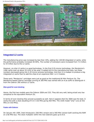
![An illustrated Guide to 6th generation CPUs
March 15, 1999. The 433 MHz version of the Celeron was launched. A 466 MHz version was released
late April.
July 31, 1999. The 500 MHz version of Celeron was launched.
Later 1999 the Celeron came in a 533 MHz version. In 2000 came 566 MHz Celerons produced with 0.18-
micron process technology.
New Socket 370 for the Celeron
[top]
The 400 and 366 MHz processors were as all successors available in a plastic pin grid array (P.P.G.A.)
form factor.
This PGA370 socket looks quite like a traditional Socket 7. It holds 370 pins:
Both are ZIF (Zero Insertion Force) sockets containing a lever so you can open and close the socket.
This makes it very easy to insert the CPU.
However, the PGA uses a different bus protocol (GTL+) than the Socket 7, which also only holds 238
pins. The GTL+ bus is the same protocol as all Pentium II's. Hence, they use the same chip sets.
The socket 370 is cheaper to produce than Slot 1 cartridges, so all Intels mainstream processors will
come in this design.
The roadmap for the Celeron looks like this:
q 66 MHz bus versions up to 800 MHz.
q 100 MHz bus versions introduced in 2001, bringing the chip up to 1200 MHz.
http://www.karbosguide.com/hardware/module3e03.htm (5 of 7)7/27/2004 4:08:26 AM](https://image.slidesharecdn.com/computerrepair-acompleteillustratedguidetopchardware-140318001250-phpapp01/85/Computer-repair-_a_complete_illustrated_guide_to_pc_hardware-404-320.jpg)
![An illustrated Guide to 6th generation CPUs
Dual Celeron configuration
Using two Celerons on one motherboard could be a great idea. It would enable people to produce very
inexpensive high-powered workstations. Windows NT is capable of using both processors.
During 1998 I heard of several private persons, who made the Celerons work in dual SMP (symmetric
multiprocessing) configurations. But in July 1999 two companies produce motherboards for dual Celeron
configuration.
Here is a little picture of such a board. You see two socket 370's:
See Abits own homepage on the BP6 board. And see QDI.
q Next page
q Previous page
Learn more [top]
Read about chip sets on the motherboard in module 2d
http://www.karbosguide.com/hardware/module3e03.htm (6 of 7)7/27/2004 4:08:26 AM](https://image.slidesharecdn.com/computerrepair-acompleteillustratedguidetopchardware-140318001250-phpapp01/85/Computer-repair-_a_complete_illustrated_guide_to_pc_hardware-405-320.jpg)
![An illustrated Guide to 6th generation CPUs
Read more about RAM in module 2e
Read module 5a about expansion cards, where we evaluate the I/O buses from the port side.
Read module 5b about AGP and module 5c about Firewire.
Read module 7a about monitors, and 7bon graphics card.
Read module 7c about sound cards, and 7d on digital sound and music.
[Main page] [Contact] [Karbo's Dictionary] [The Software Guides]
Copyright (c) 1996-2001 by Michael B. Karbo. www.karbosguide.com.
http://www.karbosguide.com/hardware/module3e03.htm (7 of 7)7/27/2004 4:08:26 AM](https://image.slidesharecdn.com/computerrepair-acompleteillustratedguidetopchardware-140318001250-phpapp01/85/Computer-repair-_a_complete_illustrated_guide_to_pc_hardware-406-320.jpg)
![An illustrated Guide to 6th generation CPUs
KarbosGuide.com. Module 3e.04
About P6-like processors from AMD and Cyrix
The contents:
q AMD's powerfull K6
q AMD's K6-2
q Cyrix 6x86MX
q Pure CISC
q Two brands of 6X86MX
q K6-2
q Next page
q Previous page
K6
[top]
Intel's Pentium II soon got competition from AMD and Cyrix. Both companies have launched
several good processors, sometimes giving Intel a hard competiton.
AMD's K6 is from April 2, 1997. In 1996 AMD produced the K5 processor which was not very
impressive, however very cheap. The company was put back to business by Mr. Atiq Raza,
who brought in the technology from NexGen. This lead to the very successful model K6,
which saved AMD from ruin.
The market soon discovered that the K6 performed a lot better than Pentium MMX, which it
shared the Socket 7 motherboards with. Here are the data:
http://www.karbosguide.com/hardware/module3e04.htm (1 of 8)7/27/2004 4:08:29 AM](https://image.slidesharecdn.com/computerrepair-acompleteillustratedguidetopchardware-140318001250-phpapp01/85/Computer-repair-_a_complete_illustrated_guide_to_pc_hardware-407-320.jpg)
![An illustrated Guide to 6th generation CPUs
q Equipped with 32+32 KB L1 cache and MMX.
q Containing 8.8 million transistors.
K6 is (like K5) compatible with Pentium. Thus, it can be mounted in a Socket 7 on a regular
Pentium motherboard, and this soon made the K6 very popular.
BIOS and voltage
On the older motherboards, it is possible that the BIOS has to be updated to make it work.
K6 performs best when the BIOS recognizes the chip, so its full potential can be utilized. That
requires a dual voltage motherboards. The K6-200 requires 2.9 volt for its core. The other
models require 2.8 volt as the Pentium MMX.
[top]
Please support our
sponsor.
The K6 model 7 (Little Foot) was running at 300 MHz. These high performance K6s were sold
at very reasonable prices. The problem seemed in the beginning to be to produce enough
chips. The K6 was followed by the K6-2 (and later the Athlon), which gave AMD an enormous
success in the late 1990's.
Cyrix 6X86MX (MII)
[top]
Cyrix was a
company with another high performance chips, placed somewhere between 5th and 6th
http://www.karbosguide.com/hardware/module3e04.htm (2 of 8)7/27/2004 4:08:29 AM](https://image.slidesharecdn.com/computerrepair-acompleteillustratedguidetopchardware-140318001250-phpapp01/85/Computer-repair-_a_complete_illustrated_guide_to_pc_hardware-408-320.jpg)
![An illustrated Guide to 6th generation CPUs
generation. The first models were positioned against the Pentium MMX chip from Intel. Later
models can be compared to the K6. I have to admit, that I quite seldom saw these
processors in my country, but they did exist.
Cyrix powerful P6-classed processor was announced as the "M2". Introduced on May 30,
1997 the name became 6X86MX. Later it has been named MII again. There has always been
some confusion about the identification of the Cyrix CPUs.
MMX
This 6X86MX chip is compatible with the Pentium MMX. This gives additional possibilities to
assemble PCs on ordinary Socket 7 motherboards.
The 6X86MX has 64 KB internal L1 cache, which is very impressive. Cyrix also utilizes
technologies which are not found in Pentium MMX. These chips are named to compare them
with genuine Pentiums, although their internal clock speed is lower than corresponding Intel
processors.
Pure CISC
[top]
The 6x86MX was unique compared to the other 6. generation CPUs (Pentium II and Pro and
K6) since it does not work upon a RISC kernel. 6x86MX executes the original CISC
instructions as does the Pentium MMX.
The 6x86MX has plenty of internal registers placing it in company with other 6th generation
CPU's:
CPU Number of
32 bit CPU registers
Pentium MMX 8
6x86MX 32
Pentium Pro 40
K6 48
The 6x86MX had - as all processors from Cyrix - a problem concerning the FPU unit.
However, only using standard office applications, this is of no concern. The problem arises
when you play 3D games.
Poor performance
http://www.karbosguide.com/hardware/module3e04.htm (3 of 8)7/27/2004 4:08:29 AM](https://image.slidesharecdn.com/computerrepair-acompleteillustratedguidetopchardware-140318001250-phpapp01/85/Computer-repair-_a_complete_illustrated_guide_to_pc_hardware-409-320.jpg)
![An illustrated Guide to 6th generation CPUs
The 6X86MX is quite a powerful chip - on the paper. However, there are problems with the
supply of them, and also the system bus speed caused troubles. It was difficult to find a
motherboard that accepts these speeds. They also lacked good FPU and MMX performance.
They did not incorporate the 3DNow! technology. Hopefully this will change as Cyrix has been
taken over by VIA.
6X86MX Internal speed External speed
PR166 150 MHz 60 MHz
PR200 166 MHz 66 MHz
PR233 188 MHz 75 MHz
PR266 225 MHz 75 MHz
PR300 233 MHz 66 MHz
PR333 255 MHz 83 MHz
PR433 285 MHz 95 MHz
PR466 333 MHz 95 MHz
It was evident that Cyrix intended to continue this line of processors, and this definitely was a
positive trend. Intel got competition, and it keept the well tested and inexpensive Socket 7
motherboards in the market. In 2000 the VIA Joshua processor will hold designs originating
from Cyrix - ported into socket 370 design.
Two brands of 6x86MX and MII
[top]
The 6x86MX processor was produced by National/Cyrix as well as by IBM. The architecture
were the same, but the chips were built at different plants.
On April 14, 1998 the Cyrix MII (M-two) version was launched. It was exactly the same chip
as the 6X86MX just running at higher clock frequencies. Later the voltage will be reduced to
2.2 Volts.
IBM used a new technology for their PR333 chip. It is patented and called Flip-Chip. The die is
soldered directly to the ceramic casing and this causes less induction.
Cyrix MIII
http://www.karbosguide.com/hardware/module3e04.htm (4 of 8)7/27/2004 4:08:29 AM](https://image.slidesharecdn.com/computerrepair-acompleteillustratedguidetopchardware-140318001250-phpapp01/85/Computer-repair-_a_complete_illustrated_guide_to_pc_hardware-410-320.jpg)
![An illustrated Guide to 6th generation CPUs
In the year 2000 we were expecting the 3rd generation of the 6X86MX (code name Jalapeno
and Mojave). This CPU was to be named MIII, and to come in>600 MHz flavors. The MXi was
intended Socket 7 compatible, with a core running on a 133 MHz system bus. It also should
include 3DNow! instructions and improved FPU. Read more on this.
AMD K6-2
[top]
The next AMD "model 8" version of the K6 had the code name "Chomper".
This processor of May 28, 1998 was marketed as K6-2, and like the model 7 version of the
original K6, it is manufactured with 0.25 micron technology. These chips run on just 2.2
Voltage. They became an immense succes, in many situations competing very successfully
with Intel's Pentium II.
Super 7 motherboards and better MMX
The K6-2 is made for a front side bus (system bus) at the speed of 100 MHz. This is to be
found with the so-called Super 7 motherboards. AMD made other vendors like VIA produce
new chipsets for the traditional socket 7 motherboards, after Intel in 1997 had given up the
platform.
K6-2 is also improved with an MMX performance twofold better compared to the original K6.
3DNow!
http://www.karbosguide.com/hardware/module3e04.htm (5 of 8)7/27/2004 4:08:29 AM](https://image.slidesharecdn.com/computerrepair-acompleteillustratedguidetopchardware-140318001250-phpapp01/85/Computer-repair-_a_complete_illustrated_guide_to_pc_hardware-411-320.jpg)
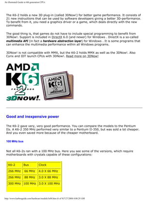
![An illustrated Guide to 6th generation CPUs
333 MHz 95 MHz 3.5 X 95 MHz
350 MHz 100 MHz 3.5 X 100 MHz
380 MHz 95 MHz 4.0 X 95 MHz
400 MHz 100 MHz 4.0 X 100 MHz
Two of the CPU's in the table must be the same. AMD calls it a 350 MHz version, but in
Denmark e.g it was sold as a 380 MHz version.
K6-2/400 and above
November 15, 1998. The K6-2/400 was introduced. This chip worked on a new core, which
should be slightly improved. Hence the performance matched a Pentium II-400.
April 6, 1999. A 475 MHz version of the K6-2 was introduced. The latest version is 533 MHz.
AMD had 39% of the market with K6-2 in 1999!
q Next page
q Previous page
Learn more [top]
Read about chip sets on the motherboard in module 2d
Read more about RAM in module 2e
Read module 5a about expansion cards, where we evaluate the I/O buses from the port side.
Read module 5b about AGP and module 5c about Firewire.
Read module 7a about monitors, and 7b on graphics card.
Read module 7c about sound cards, and 7d on digital sound and music.
[Main page] [Contact] [Karbo's Dictionary] [The Software Guides]
http://www.karbosguide.com/hardware/module3e04.htm (7 of 8)7/27/2004 4:08:29 AM](https://image.slidesharecdn.com/computerrepair-acompleteillustratedguidetopchardware-140318001250-phpapp01/85/Computer-repair-_a_complete_illustrated_guide_to_pc_hardware-413-320.jpg)
![An illustrated Guide to 6th generation CPUs
Please click the banners to support our work!
KarbosGuide.com. Module 3e.05
The AMD K6-3
The contents:
q K6-3
q K6-2+
q Next page
q Previous page
K6-3 [top]
Please support our
sponsor.
AMD announced the very powerful K6-3 for quite a long time. It was delayed quite a while,
should have been released February 22nd 1999. During the delay Intel had time establish its
Socket 370 version of Celeron. But finally it arrived in the summer of 1999.
Using the next version of this chip - model 9 code name "Sharptooth" - you may have three
levels of cache!
http://www.karbosguide.com/hardware/module3e05.htm (1 of 4)7/27/2004 4:08:31 AM](https://image.slidesharecdn.com/computerrepair-acompleteillustratedguidetopchardware-140318001250-phpapp01/85/Computer-repair-_a_complete_illustrated_guide_to_pc_hardware-415-320.jpg)
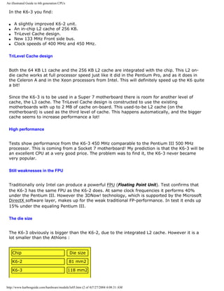
![An illustrated Guide to 6th generation CPUs
K7 Athlon 0.25 micron 184 mm2
K7 Athlon 0.18 micron 100 mm2
Intel Pentium III Cumine 106 mm2
K6-2+
In 2000 the K6-3 is expected to disappear from the market. It never became a success.
However, the K6-2 has been a great seller, so AMD will launche new versions of the K6-3 as
K6-2+.
This new chip will have following features:
q 0.18 micron process technology
q Integrated 256 KB L2 cache
q Additional 3DNow! instructions (from Athlon)
q 550 MHz
The maximum speed from this design is expected to be 750 MHz. Hence one can expect the
Socket7 platform soon to die out.
q Next page
q Previous page
Learn more [top]
Read about chip sets on the motherboard in module 2d
Read more about RAM in module 2e
Read module 5a about expansion cards, where we evaluate the I/O buses from the port side.
Read module 5b about AGP and module 5c about Firewire.
http://www.karbosguide.com/hardware/module3e05.htm (3 of 4)7/27/2004 4:08:31 AM](https://image.slidesharecdn.com/computerrepair-acompleteillustratedguidetopchardware-140318001250-phpapp01/85/Computer-repair-_a_complete_illustrated_guide_to_pc_hardware-417-320.jpg)
![An illustrated Guide to 6th generation CPUs
Read module 7a about monitors, and 7b on graphics card.
Read module 7c about sound cards, and 7d on digital sound and music.
[Main page] [Contact] [Karbo's Dictionary] [The Software Guides]
Copyright (c) 1996-2001 by Michael B. Karbo. www.karbosguide.com.
http://www.karbosguide.com/hardware/module3e05.htm (4 of 4)7/27/2004 4:08:31 AM](https://image.slidesharecdn.com/computerrepair-acompleteillustratedguidetopchardware-140318001250-phpapp01/85/Computer-repair-_a_complete_illustrated_guide_to_pc_hardware-418-320.jpg)
![An illustrated Guide to 6th generation CPUs
Please click the banners to support our work!
KarbosGuide.com. Module 3e.06
Intel Xeon for servers
The contents:
q Xeon
q A product for servers
q Next page
q Previous page
Pentium II Xeon [top]
Please support our
sponsor.
Intel always had an important market supplying CPU's for servers. The original Pentium Pro
http://www.karbosguide.com/hardware/module3e06.htm (1 of 4)7/27/2004 4:08:32 AM](https://image.slidesharecdn.com/computerrepair-acompleteillustratedguidetopchardware-140318001250-phpapp01/85/Computer-repair-_a_complete_illustrated_guide_to_pc_hardware-419-320.jpg)
![An illustrated Guide to 6th generation CPUs
was for several years used for this purpose. Xeon is a line of CPUs for use in servers.
On July 26th, 1998 Intel introduced the Pentium II cartridge named Xeon. Aimed at servers
and perhaps high-end users.
The Xeon is a Pentium II in a new cartridge fitting into a new connector called Slot Two. The
module is twice as tall as the current Pentium II, but there are other important innovations
and improvements:
q New type L2 cache RAM chips: CSRAM (Custom SRAM), which runs at full CPU speed.
q Different L2 cache sizes: 512, 1,024, or 2,048 KB L2 RAM.
q Up to 8 GB RAM can be cached.
q Up to four or even eight Xeons in one server.
q Support for clustered servers.
q New chip sets 82440GX and 82450NX.
The new (huge) cartridge fits into a new Slot Two with three layers of edge connectors. The
large L2 caches running high speed will use a lot of power, so cooling will be very important.
The cartridge is about twice the size of the well known Pentium II.
A server product
[top]
The Xeon chip is for high performance servers. The first top model will hold 2 MB L2 cache on
the cartridge, running at full 450 MHz. This chip costs $4,500!
Performance gain from L2 cache at full speed
The L2 cache of the Xeon runs at full CPU clock speed. One could think, that this would have
the same performance as the L1 cache. However the interface from L1 to L2 costs some clock
http://www.karbosguide.com/hardware/module3e06.htm (2 of 4)7/27/2004 4:08:32 AM](https://image.slidesharecdn.com/computerrepair-acompleteillustratedguidetopchardware-140318001250-phpapp01/85/Computer-repair-_a_complete_illustrated_guide_to_pc_hardware-420-320.jpg)
![An illustrated Guide to 6th generation CPUs
ticks in the beginning of each transmission, so there is some latency. But when data is
transferred, it runs at full clock speed.
Practical tests only show an increase in the performance of 5-8% comparing Pentium II and
Xeon/512 KB, both running at 450 MHz.
Personally, I find the Xeons too expensive. I know companies who have been advised to and
bought the modules with 2 MB cache for use in web-servers. Obviously the price does not
matter in those cases, and Intel makes a good profit from that. I do not think the
performance matches the price.
Tanner
In 1999 the code name “Tanner” chip became known as the Pentium III Xeon.
Later might follow the processor code named "Foster" which should integrate 2 MB of L2
cache in-chip.
q Next page
q Previous page
Learn more [top]
Read about chip sets on the motherboard in module 2d
Read more about RAM in module 2e
Read module 5a about expansion cards, where we evaluate the I/O buses from the port side.
Read module 5b about AGP and module 5c about Firewire.
Read module 7a about monitors, and 7b on graphics card.
Read module 7c about sound cards, and 7d on digital sound and music.
[Main page] [Contact] [Karbo's Dictionary] [The Software Guides]
http://www.karbosguide.com/hardware/module3e06.htm (3 of 4)7/27/2004 4:08:32 AM](https://image.slidesharecdn.com/computerrepair-acompleteillustratedguidetopchardware-140318001250-phpapp01/85/Computer-repair-_a_complete_illustrated_guide_to_pc_hardware-421-320.jpg)
![An illustrated Guide to 6th generation CPUs
Please click the banners to support our work!
KarbosGuide.com. Module 3e.07a
The Pentium III - Katmai and SSE
The contents:
q Katmai New Instructions (KNI)
q Two new features
q The ID number – panic, panic
q SSE
q New registers
q Program support with DirectX 6.1
q My conclusion
q Next page
q Previous
page
The first P6 CPU from Intel was the Pentium Pro. Later we got the Pentium II in various
flavours (including the popular Celeron). In 1999 the time came for the Pentium III.
Katmai New Instructions (KNI)
[top]
In March 1999 Intel introduced the new enhanced MMX2 set of graphics instructions (70 of
them). These are called Katmai New Instructions (KNI) or SSE. They are intended to speed
up 3D gaming performance - just like AMD's 3DNow! technology. Katmai includes "double
precision floating point single instruction multiple data" (or DPFS SIMD for short) running in
http://www.karbosguide.com/hardware/module3e07a.htm (1 of 5)7/27/2004 4:08:34 AM](https://image.slidesharecdn.com/computerrepair-acompleteillustratedguidetopchardware-140318001250-phpapp01/85/Computer-repair-_a_complete_illustrated_guide_to_pc_hardware-423-320.jpg)
![An illustrated Guide to 6th generation CPUs
eight 128 bit registers.
Katmai New Instructions (KNI) was introduced with the 450 and 500 MHz Pentium III. It was
processors very similar to the old Pentium IIs, using Slot 1.
The only new feature was the implementation of Katmai and SSE, which I shall try to
describe in this page.
Two new features [top]
Please support our
sponsor.
In fact the Pentium III contained two rather different news items, one small and one
somewhat bigger. Intel's new top processor is a Pentium II in principle. It is mounted in a BX
based motherboard with Slot 1. This processor has some built-in features:
q A rather problematic ID numbering.
q New registers and 70 new instructions.
Finally the clock speed was raised to 500 MHz with room for further increases. Pentium III
Xeon (code name Tanner) was introduced March 17th, 1999. It was a Xeon chip updated with
all the new features from Pentium III. To utilize it Intel has the 840 chipset.
The ID number – panic, panic
[top]
http://www.karbosguide.com/hardware/module3e07a.htm (2 of 5)7/27/2004 4:08:34 AM](https://image.slidesharecdn.com/computerrepair-acompleteillustratedguidetopchardware-140318001250-phpapp01/85/Computer-repair-_a_complete_illustrated_guide_to_pc_hardware-424-320.jpg)
![An illustrated Guide to 6th generation CPUs
The ID number PSN (Processor Serial Number), which is unique for each CPU, has caused lots
of security discussions. It is a 96 bit value that is electronically programmed into each chip.
Actually it was meant as a very sensible initiative, which could make electronic trade and
encrypting on the Internet more secure and effective.
The advocates see the ID number as "the permanent cookie."However it turns out that
hackers and crackers can easily access the number, which makes the security dubious. At the
same time the system is proposing a global registry of Internet users, which can easily be
misused for marketing, etc. That will be invasion of privacy, if you no longer can remain
anonymous on the Internet.
SSE etc.
[top]
The somewhat bigger news item is a real change in the basic processor architecture. It is
actually the first change since 1985, where the x86 architecture was expanded from 16 to 32
bit (compared with the 386 processor).
q New 128 bit registers, which each can handle four floating-point numbers.
q Streaming SIMD Extensions (SSE). 50 new instructions, which enable simultaneous,
advanced calculations of more floating-point numbers with a single instruction.
q New Media Instructions. 12 new instructions in this category, which include other
instructions for floating-point decimal calculations besides instructions that are designed for
coding and decoding of MPEG-2 video streams "on the fly."
q Streaming Memory. Here are 8 new instructions, which improve the interaction between L2-
cache and RAM. With optimum utilization of the instructions, it could result in a 20%
improvement of the bandwidth on the system bus. These instructions require newly-compiled
programs, so it may be some time before we see the effect of this.
The combined new instructions are called KNI (Katmai New Instructions) or SSE. The Pentium
III construction is an attempt at improving the FPU performance in the processor. The
registers are used by the new Katmai instructions.
New registers
[top]
The new 128 bit registers can potentially speed up 3D-graphics and multimedia handling,
since the registers can contain four of the important 32 bit floating-point decimal numbers.
Since the registers are a new physical creation within the CPU, they require support in the
operating system to utilize them. Such support is expected soon in Windows 98.
http://www.karbosguide.com/hardware/module3e07a.htm (3 of 5)7/27/2004 4:08:34 AM](https://image.slidesharecdn.com/computerrepair-acompleteillustratedguidetopchardware-140318001250-phpapp01/85/Computer-repair-_a_complete_illustrated_guide_to_pc_hardware-425-320.jpg)
![An illustrated Guide to 6th generation CPUs
Program support with DirectX
[top]
Microsoft's DirectX program layer is optimized relative to Katmai. With that, a large number
of existing programs should benefit from the additional power of Pentium III (when DirectX
6.1 or better is installed). However the drivers for sound and graphics cards need to be re-
written, to enable utilization of the new DirectX edition. Games that are not based on DirectX
need to be re-written or expanded with patches, which utilize Katmai. Finally, a patch has
been announced for the operating system itself, Windows 98, which should support the new
instructions. Whether it will support all or only part of them is yet unknown.
Problems
In April 1999 came reports of heat problems with the 550 MHz version. It should be very very
hot, so big fans are the issue here...
July 31, 1999. The 600 MHz version was launched. Later the "Coppermine" version was
introduced with Socket370, as you will see in the following page.
A provisional evaluation
[top]
It is difficult to evaluate the significance of Pentium III’s new registers and instructions.
However, it seems that most programs, drivers, etc. are being tuned for the new instructions.
Then there is no doubt that the multimedia capabilities have received a great boost. There
could be a doubling of their performance. So far Adobe have included support for SSE in
version 5.5 of Photoshop. This works very well, some very time-consuming processes has
been shortened with approx. 40%.
The question is, if AMD will be forced to work in SSE etc. in their top processors or if they will
continue the development of 3DNow!. In that case we'll have two systems to work with.
Perhaps this is not a problem.
Please read about Cumine and other new chips following Pentium III in the next module.
q Next page
q Previous page
http://www.karbosguide.com/hardware/module3e07a.htm (4 of 5)7/27/2004 4:08:34 AM](https://image.slidesharecdn.com/computerrepair-acompleteillustratedguidetopchardware-140318001250-phpapp01/85/Computer-repair-_a_complete_illustrated_guide_to_pc_hardware-426-320.jpg)
![An illustrated Guide to 6th generation CPUs
Learn more [top]
Read about chip sets on the motherboard in module 2d
Read more about RAM in module 2e
Read module 5a about expansion cards, where we evaluate the I/O buses from the port side.
Read module 5b about AGP and module 5c about Firewire.
Read module 7a about monitors, and 7b on graphics card.
Read module 7c about sound cards, and 7d on digital sound and music.
[Main page] [Contact] [Karbo's Dictionary] [The Software Guides]
Copyright (c) 1996-2001 by Michael B. Karbo. www.karbosguide.com.
http://www.karbosguide.com/hardware/module3e07a.htm (5 of 5)7/27/2004 4:08:34 AM](https://image.slidesharecdn.com/computerrepair-acompleteillustratedguidetopchardware-140318001250-phpapp01/85/Computer-repair-_a_complete_illustrated_guide_to_pc_hardware-427-320.jpg)
![An illustrated Guide to 6th generation CPUs
Please click the banners to support our work!
KarbosGuide.com. Module 3e.07b
Pentium III CuMine
The contents:
q CuMine
q Many models
q But no copper
q Next page
q Previous page
Coppermine - CuMine..
[top]
Here we shall look at the further development of Pentium III.
600 MHz
31, July 1999 the Pentium III was released in a 600 MHz version. This chip is working on a
100 MHz bus.
27, September 1999, Intel launched two new chips, the 533 and the 600 MHz versions of
Pentium III. These chips are both running on a 133 MHz system bus. Unfortunately the new
chip set, i820, which was to be launched the same day, was pulled back in the last minute.
http://www.karbosguide.com/hardware/module3e07b.htm (1 of 4)7/27/2004 4:08:36 AM](https://image.slidesharecdn.com/computerrepair-acompleteillustratedguidetopchardware-140318001250-phpapp01/85/Computer-repair-_a_complete_illustrated_guide_to_pc_hardware-428-320.jpg)
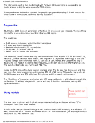
![An illustrated Guide to 6th generation CPUs
Model Process Clock frequency
600 0.25 6 x 100 MHz
600E 0.18 6 x 100 MHz
600B 0.25 4.5 x 133 MHz
600EB 0.18 4.5 x 133 MHz
Obviously, Intel plans to skip the chips produced in 0.25 micron. But meanwhile both process
technologies will be sold side by side.
Late we shall have Celerons at 800 MHz and more based on the new CuMine kernel.
But no copper
It was expected this new generation of chips to produced using copper. The name "CuMine"
also indicates this. But the first of these Cumines are produced with traditional aluminium
wiring in 0.18 microns width. First in 2001 Intel plans to start using copper (in the P860
kernel), and this should lead to much higher levels of speed.
AMD launched GigaHerz version of the Athlon using copper in 2000. Intel also launched
GigaHertz versions of Pentium III, but they were only sold in few numbers in 2000.
SpeedStep
Intel launched a new series of chips for notebooks. The first models are 500 MHz versions of
Pentium III running on a 100 MHz bus. Producing them in 0.18 techology, Intel has been able
to work with the power consumption.
The new chips can work in a "light" mode when the notebook is on batteries. The core
voltage is reduced from 1.6 to 1.1 Volt, and the power usage goes down to just 50%! The
CPU performance only decreases with 20%.
q Next page
q Previous page
Learn more [top]
http://www.karbosguide.com/hardware/module3e07b.htm (3 of 4)7/27/2004 4:08:36 AM](https://image.slidesharecdn.com/computerrepair-acompleteillustratedguidetopchardware-140318001250-phpapp01/85/Computer-repair-_a_complete_illustrated_guide_to_pc_hardware-430-320.jpg)
![An illustrated Guide to 6th generation CPUs
Read about chip sets on the motherboard in module 2d
Read more about RAM in module 2e
Read module 5a about expansion cards, where we evaluate the I/O buses from the port side.
Read module 5b about AGP and module 5c about Firewire.
Read module 7a about monitors, and 7b on graphics card.
Read module 7c about sound cards, and 7d on digital sound and music.
[Main page] [Contact] [Karbo's Dictionary] [The Software Guides]
Copyright (c) 1996-2001 by Michael B. Karbo. www.karbosguide.com.
http://www.karbosguide.com/hardware/module3e07b.htm (4 of 4)7/27/2004 4:08:36 AM](https://image.slidesharecdn.com/computerrepair-acompleteillustratedguidetopchardware-140318001250-phpapp01/85/Computer-repair-_a_complete_illustrated_guide_to_pc_hardware-431-320.jpg)
![An illustrated Guide to 6th generation CPUs
Please click the banners to support our work!
KarbosGuide.com. Module 3e.07c
The further development of Pentium III
The contents:
q Pentium III
q The Pentium 4
q Next page
q Previous page
CuMine in year 2000
[top]
Here we shall look at the further development of Pentium III.
Athlon was not not good for Intel
In the first months of 2000 it was obvious that Intel had a hard time with Pentium III. From unknown
reasons, they were not capable of producing the CPUs the market wanted. In Denmark we could get all
the Athlons needed in February, but only very few Pentium IIIs.
At the same time AMD showed up with faster and cheaper versions of the Athlon - all putting a heavy
pressure on Intel.
Intel on their side launched a lot of new models. On Jan 11th, 2000 the 800 MHz version was launched
running 6 x 133 MHz. In February the company showed a Pentium III running at 1 Ghz without special
cooling.
The 850 and 866 MHz were scheduled for February 27/28, 2000. The 933 MHz model came May 27,
http://www.karbosguide.com/hardware/module3e07c.htm (1 of 4)7/27/2004 4:08:38 AM](https://image.slidesharecdn.com/computerrepair-acompleteillustratedguidetopchardware-140318001250-phpapp01/85/Computer-repair-_a_complete_illustrated_guide_to_pc_hardware-432-320.jpg)
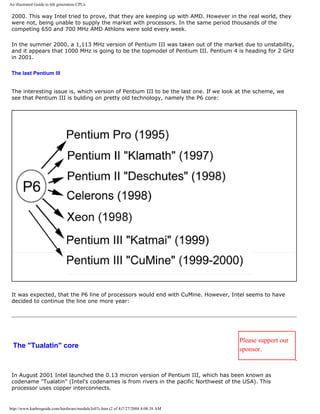
![An illustrated Guide to 6th generation CPUs
The new processor is a Pentium III "Cumine" with 256 or 512 KB L2 cache integrated. Hardware data
prefecth is a new feature, which gives an 8-10% increase in performance.
It runs on 1.475 Volt and is mounted in a Socket370. The Tualatin comes in 1.2 and 1.13 GHz versions,
both using a 133 MHz Front Side Bus.
The Intel i815EEA chipset is designed to this processor as well as VIA Apollo Pro 266T. The latest gives
support for DDR RAM.
Marketing ...
This the last Pentium III processor has not been advertised very much. Probably Intel does not want it
to compete with the 1.4 GHz Pentium 4. Many people was looking forward to the 1.2 GHZ model with
512 KB cache. However this one is only sold for use in servers and in mobile PCs - not for desktop use!
The Pentium 4
The roadmap Intel made several years ago was to abandon the P6 core in favour of a completely new
core. The processor codenamed "Willamette" should be the first of a new line of IA32 processors, which
should be marketed side-by-side to the IA64 Itanium ("Merced"):
Read about the Pentium 4 in a following module.
q Next page
q Previous page
Learn more [top]
The Pentium 4
Read about chip sets on the motherboard in module 2d
http://www.karbosguide.com/hardware/module3e07c.htm (3 of 4)7/27/2004 4:08:38 AM](https://image.slidesharecdn.com/computerrepair-acompleteillustratedguidetopchardware-140318001250-phpapp01/85/Computer-repair-_a_complete_illustrated_guide_to_pc_hardware-434-320.jpg)
![An illustrated Guide to 6th generation CPUs
Read more about RAM in module 2e
Read module 5a about expansion cards, where we evaluate the I/O buses from the port side.
Read module 5b about AGP and module 5c about Firewire.
Read module 7a about monitors, and 7b on graphics card.
Read module 7c about sound cards, and 7d on digital sound and music.
[Main page] [Contact] [Karbo's Dictionary] [The Software Guides]
Copyright (c) 1996-2001 by Michael B. Karbo. www.karbosguide.com.
http://www.karbosguide.com/hardware/module3e07c.htm (4 of 4)7/27/2004 4:08:38 AM](https://image.slidesharecdn.com/computerrepair-acompleteillustratedguidetopchardware-140318001250-phpapp01/85/Computer-repair-_a_complete_illustrated_guide_to_pc_hardware-435-320.jpg)
![An illustrated Guide AMD K7 Athlon.
Please click the banners to support our work!
KarbosGuide.com. Module 3e.08a
AMD "The Great" Athlon.
The contents:
q An introduction to K7 Athlon
q The background
q No system bus
q Next page
q Previous page
An overview of Athlon
[top]
The Athlon is a powerful CPU, the first 7th generation CPU in my opinion. It was expected June 1999 but
was delayed until August 1999. Intel's response (code name Willamette) was scheduled October 2000.
Athlon was designed using technologies from DEC Alpha 21064 and 2162 RISC processors. Their "farther"
Dirk Meyer came to AMD and brought in an engineering team who succesfully developed the Athlon, which
ended up being an enormous success to AMD.
Within the first months, the markets response to the Athlon was very positive. It seemed (as expected) to
outperform the Pentium III at same clock frequency.
Let us look at what Athlon has to offer:
Raw data
q Mounting in a Pentium II like module, which is entirely AMD’s own design. The socket is called slot A.
q A clock speed of 500 MHz in the first versions.
q Up to 8 MB L2-cache (minimum 512 Kb, without extra TAG-RAM).
q 128 KB L1-cache.
http://www.karbosguide.com/hardware/module3e08a.htm (1 of 5)7/27/2004 4:08:41 AM](https://image.slidesharecdn.com/computerrepair-acompleteillustratedguidetopchardware-140318001250-phpapp01/85/Computer-repair-_a_complete_illustrated_guide_to_pc_hardware-436-320.jpg)
![An illustrated Guide AMD K7 Athlon.
q 22 million transistors (the original Pentium III had 9.3 million).
New bus type
q A brand new system bus type, which in the first versions will work at 200 MHz. An increase to 400 MHz is
expected later. The bus is ready for new fast RAM types.
q Independent backside bus, which connects the L2 cache. Here the clock speed can be 1/4, 1/3, 2/5 or
identical with the internal CPU frequency. That is the same system which is used in the P6 systems where
the L2 speed is either half (Pentium II and III Katmai) or full CPU frequency (at Celeron, Xeons and Pentium
III CuMine).
Heavy decoding and FPU
q Three instruction decoders, which translate the X86 program's CISC instructions to the effective RISC
instructions, ROP’s, where up to 9 can be executed simultaneously. The first test show a decoding of 2.8
CISC-instruction per clock cycle. This is roughly 30% better than Pentium II and III.
q Can handle and rearrange up to 72 instructions (ROP out of order) simultaneously (Pentium III can do 40,
K6-2 only 24).
q Enormous FPU performance with three simultaneous instructions and one GFLOP at 500 MHz (1 billion
floating-point number operations per second) with 80 bit floating-point numbers. Two GFLOP with MMX and
3DNow! instructions. That at least equals Pentium III’s performance with full utilization of Katmai. The
3DNow! engine has even been improved comparing to the K6-3.
The first tests show this FPU performance:
Processor FPU
Winmark
Intel Pentium III/500
MHz
2562
AMD Athlon /500 MHz 2767
The background [top]
Please support our
sponsor.
AMD has no license to use the Slot 1 architecture, so the controlling logic comes from Digital Equipment
Corp. It is called EV6 and was designed for the 21264 Alpha CPU. AMD developed the first chip sets (750)
themselves, but the architecture is royalty free to use. It will be AMD's first processor using a motherboard
and chip set specially designed by themselves. VIA has developed a series of chip sets for the Athlon.
The use of the EV6 bus gives a lot more bandwidth than the Intel GTL+. This means that the Athlon has the
http://www.karbosguide.com/hardware/module3e08a.htm (2 of 5)7/27/2004 4:08:41 AM](https://image.slidesharecdn.com/computerrepair-acompleteillustratedguidetopchardware-140318001250-phpapp01/85/Computer-repair-_a_complete_illustrated_guide_to_pc_hardware-437-320.jpg)
![An illustrated Guide AMD K7 Athlon.
capacity to work with new RAM types such as RDRAM. Also the use of 128 KB L1 cache is pretty heavy. The
L1 cache is important when the clock speed increases and 128 KB is twice the size in Pentium II's.
The Athlon came in several versions. The "slowest" ones will have the L2 cache running at one third of the
CPU speed, where the best ones (like "Thunderbird") work at full CPU speed (as the Xeons do). The Athlon
was intended to give Intel competition in all segments including servers, where the topmodels are being
compareable with the best Intel Xeon processors.
No system bus
[top]
Since the Athlon is not installed in the same way as Pentium II and III, AMD could develop a brand new
architecture. This means that there really is no system bus. The Athlon module is connected directly to
chipset's "North bridge" in the first edition through a 200 MHz data channel. In a multi-processor system,
each CPU will have its own 200 MHz channel.
That channel connects only two units: the CPU and the chipset. In the P6 systems the CPU, L2-cache, RAM,
PCI units, the AGP unit and the chipset are all connected to the system bus. In Athlon the traffic is split.
North bridge comes first, then come RAM, AGP, the PCI units and the South bridge.
http://www.karbosguide.com/hardware/module3e08a.htm (3 of 5)7/27/2004 4:08:41 AM](https://image.slidesharecdn.com/computerrepair-acompleteillustratedguidetopchardware-140318001250-phpapp01/85/Computer-repair-_a_complete_illustrated_guide_to_pc_hardware-438-320.jpg)
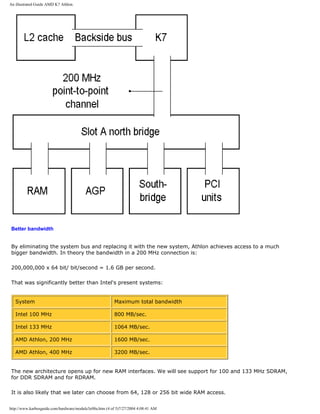
![An illustrated Guide AMD K7 Athlon.
q Next page
q Previous page
Learn more [top]
Read about chip sets on the motherboard in module 2d
Read more about RAM in module 2e
Read module 5a about expansion cards, where we evaluate the I/O buses from the port side.
Read module 5b about AGP and module 5c about Firewire.
Read module 7a about monitors, and 7b on graphics card.
Read module 7c about sound cards, and 7d on digital sound and music.
[Main page] [Contact] [Karbo's Dictionary] [The Software Guides]
Copyright (c) 1996-2001 by Michael B. Karbo. www.karbosguide.com.
http://www.karbosguide.com/hardware/module3e08a.htm (5 of 5)7/27/2004 4:08:41 AM](https://image.slidesharecdn.com/computerrepair-acompleteillustratedguidetopchardware-140318001250-phpapp01/85/Computer-repair-_a_complete_illustrated_guide_to_pc_hardware-440-320.jpg)
![An illustrated Guide AMD K7 Athlon.
Please click the banners to support our work!
KarbosGuide.com. Module 3e.08b
AMD K7 "The Great" Athlon.
The contents:
q The Athlon Tbird
q The Sledgehammer
q Next page
q Previous
page
The Thunderbird Athlons
[top]
The Athlon processor has a very large potential. Back in 1999 some analytics believed that
Athlon will be the most important and dominant processor in 2001. And they were almost
right. All major vendors - except Dell - are using Athlons in high-end PCs.
The Athlon has an enormous bandwidth that obviously not will be needed in the immediate
future.
The point is that the architecture is looking ahead. There is lots of room for technological
advances in the coming years, such as significantly faster RAM, hard disk etc.
At the same time AMD signals that this is the future server architecture, since especially
larger network servers will have a need for the large bandwidth.
http://www.karbosguide.com/hardware/module3e08b.htm (1 of 5)7/27/2004 4:08:43 AM](https://image.slidesharecdn.com/computerrepair-acompleteillustratedguidetopchardware-140318001250-phpapp01/85/Computer-repair-_a_complete_illustrated_guide_to_pc_hardware-441-320.jpg)
![An illustrated Guide AMD K7 Athlon.
One of the limitations of the 32 bit architecture is the amount of RAM. A 32 bit processor can
"only" address 4 Gb of RAM. This is not enough for the biggest systems.
With 64 bit addressing you can use 18 Exebytes of RAM. That's a lot.
Sledgehammer will be introduced in 2002.
Please also see the article on die sizes here.
q Next page
q Previous page
Learn more [top]
Read about chip sets on the motherboard in module 2d
Read more about RAM in module 2e
Read module 5a about expansion cards, where we evaluate the I/O buses from the port side.
Read module 5b about AGP and module 5c about Firewire.
Read module 7a about monitors, and 7b on graphics card.
Read module 7c about sound cards, and 7d on digital sound and music.
[Main page] [Contact] [Karbo's Dictionary] [The Software Guides]
Copyright (c) 1996-2001 by Michael B. Karbo. www.karbosguide.com.
http://www.karbosguide.com/hardware/module3e08b.htm (5 of 5)7/27/2004 4:08:43 AM](https://image.slidesharecdn.com/computerrepair-acompleteillustratedguidetopchardware-140318001250-phpapp01/85/Computer-repair-_a_complete_illustrated_guide_to_pc_hardware-445-320.jpg)
![An illustrated Guide to 6th generation CPUs
Please click the banners to support our work!
KarbosGuide.com. Module 3e.09
On MMX, 3DNow!, and Katmai
The contents:
q An introduction
q The FPU
q Working with 3D graphics
q MMX
q 3DNow!
q Katmai
q Next page
q Previous page
Multimedia, MMX and Katmai
[top]
http://www.karbosguide.com/hardware/module3e09.htm (1 of 6)7/27/2004 4:08:45 AM](https://image.slidesharecdn.com/computerrepair-acompleteillustratedguidetopchardware-140318001250-phpapp01/85/Computer-repair-_a_complete_illustrated_guide_to_pc_hardware-446-320.jpg)
![An illustrated Guide to 6th generation CPUs
With the Pentium MMX we had the first of several improvements of the microprocessor's set
of instructions. Later, we got 3DNow! and Katmai. What does all this mean?
In 1995 the Pentium processor was expanded with the so-called MMX instructions. That was
announced as a multimedia expansion with 57 new instructions.
Today the emphasis in multimedia is especially in 3D graphics. Here the most important
operation is the so-called geometric transformations, which deal with floating-point numbers.
Let us take a look at these issues.
FPU
[top]
FPU stands for Floating-point Unit. That is the unit in the processor, that handles floating-
point numbers. It is difficult for the CPU to manipulate floating-point numbers, since it
requires lots and lots of bits to perform an accurate calculation. Math with integers is much
simpler, and is done with hundred percent accuracy each time.
The FPU works with floating - point numbers of various bit length, depending on the desired
degree of accuracy. The most accurate type has a bit length of 80!
All the modern P6 processors have 8 FP registers, each of which has a bit length of 80. So
there is room inside the CPU itself for 8 numbers each of 80 bit length or, for example, 16
numbers each of 32 bit length. Read more...
Working with 3D graphics [top]
Please support our
sponsor.
When you draw people and landscapes, which are altered in 3D graphics, the figures are built
up from small polygons (usually triangles or rectangles).
A figure in a PC game can typically be built from 200-1500 such polygons. For each change in
the picture these polygons have to be re-drawn in a new position. This means that each
corner (vertex) in every polygon has to be recalculated.
Floating-point number operations
To calculate the placement of the polygons, you need to use floating-point numbers. Integer
calculations (1, 2, 3, 4 etc.) are not nearly precise enough. Instead, you use decimal
http://www.karbosguide.com/hardware/module3e09.htm (2 of 6)7/27/2004 4:08:45 AM](https://image.slidesharecdn.com/computerrepair-acompleteillustratedguidetopchardware-140318001250-phpapp01/85/Computer-repair-_a_complete_illustrated_guide_to_pc_hardware-447-320.jpg)
![An illustrated Guide to 6th generation CPUs
numbers such as 4.347. These numbers are single precision. They are 32 bits long. There are
also 64 bit numbers (having more decimal places). They are called double precision numbers,
which are useful for even more demanding calculations.
However the 32 bits numbers are sufficient to design 3D objects. When the figures in a 3D
landscape move, you need to make a so-called matrix multiplication to calculate the new
vertices. If a figure consists of 1000 polygons, it requires up to 84,000 multiplications, each
with two 32 bit floating-point numbers.
It is quite a hefty piece of math, for which the traditional PC is not well equipped. Actually,
the largest spreadsheet available to the finance ministry is a drop in the bucket compared to
Quake II, as far as number crunching ability is concerned.
What assists the 3D execution?
The CPU can easily run out of breath when it comes to work with 3D movements across the
screen. So what assistance can it get? That can be provided in different ways:
q Generally speaking, the faster the CPU, the higher the clock speed, the faster the
traditional FPU performance will be.
q Improvements in the CPU’s FPU with pipelines and other acceleration. We see that in each
new CPU generation.
q New instructions for more effective 3D performance. Instructions which can be called by
the programs, 3DNow! and SSE, are examples of this.
q 3D accelerated graphics cards.
MMX
[top]
The Pentium MMX processor was a big success. However, that was not because of the MMX
instructions. Many regard them as a flop.
The point is that MMX only works with integers. Furthermore the system is so weak, that it
can only work with either MMX or with FPU, not both simultaneously. That is because the two
sets of instructions share registers.
The MMX instructions can be of assistance in other tasks in the redrawing of 3D landscapes
(the surface etc.), but for all the geometry you need much more umph!
Here you see the MMX enabling in a program. It is "Painter Classic" a great drawing program,
which is bundled with Wacoms drawing tablets. The program utilizes MMX:
http://www.karbosguide.com/hardware/module3e09.htm (3 of 6)7/27/2004 4:08:45 AM](https://image.slidesharecdn.com/computerrepair-acompleteillustratedguidetopchardware-140318001250-phpapp01/85/Computer-repair-_a_complete_illustrated_guide_to_pc_hardware-448-320.jpg)
![An illustrated Guide to 6th generation CPUs
3DNow!
[top]
During the summer of 1998 AMD introduced a new collection of CPU instructions, which
improve the 3D execution.
q 21 new instructions.
q SIMD instructions, which enable handling of more data portions with just one instruction.
q Improved handling of numbers, especially the 32 bit numbers, which are used widely in 3D
games. 3DNow! became a big success, since the instructions soon became integrated in
Windows , in different games (and other programs) and in the driver programs from the
hardware producers.
The instructions use the same registers, as do MMX and traditional FPU. So they have to
share them. Since the registers are 80 bits wide, they can hold two 32 bit numbers
simultaneously.
http://www.karbosguide.com/hardware/module3e09.htm (4 of 6)7/27/2004 4:08:45 AM](https://image.slidesharecdn.com/computerrepair-acompleteillustratedguidetopchardware-140318001250-phpapp01/85/Computer-repair-_a_complete_illustrated_guide_to_pc_hardware-449-320.jpg)
![An illustrated Guide to 6th generation CPUs
Katmai [top]
Please support our
sponsor.
Katmai (SSE) is Intel's way to improve 3D execution in Pentium III. Read also the description
in module 3e7. The problem with Katmai is that the instructions require software support,
and that will take some time to get in place.
In principle Katmai is significantly more powerful than 3DNow! The 8 new 128 bit registers
can actually hold four 32 bit numbers at a time. But to take advantage of this, the FPU
pipeline should also have been doubled, so each multiplication or addition pipeline could
receive four numbers at a time.
However that was not done in Pentium III, since it would have delayed its introduction. So
the pipelines can still handle two 32 bit numbers at a time. In that way the full potential of
Katmai is not reached within the actual Pentium III design.
With the current FPU unit Pentium III can perform twice as many 32 bit number operations
per clock tick as can the other P6 processors (Pentium II and Celeron). That is the same
performance as we find in the 3DNow! processors. But Pentium III is scheduled for future
editions with a four-fold increase in FPU performance as far as the 32 bit numbers are
concerned.
SIMD
SIMD stands for Single Instruction Multiple Data. This technique was introduced in the MMX
processors, where more than one integer could be processed simultaneously. In Pentium III
this technique was given another lift, so now it can handle more than one floating-point
number. Multimedia handling especially will benefit from this, since many floating-point
number operations are handled in sound and video programs.
With the introduction of Pentium 4, the SIMD instruction set was further improved with144
new instructions.
q Next page
q Previous page
Learn more [top]
http://www.karbosguide.com/hardware/module3e09.htm (5 of 6)7/27/2004 4:08:45 AM](https://image.slidesharecdn.com/computerrepair-acompleteillustratedguidetopchardware-140318001250-phpapp01/85/Computer-repair-_a_complete_illustrated_guide_to_pc_hardware-450-320.jpg)
![An illustrated Guide to 6th generation CPUs
Read about chip sets on the motherboard in module 2d
Read more about RAM in module 2e
Read module 5a about expansion cards, where we evaluate the I/O buses from the port side.
Read module 5b about AGP and module 5c about Firewire.
Read module 7a about monitors, and 7b on graphics card.
Read module 7c about sound cards, and 7d on digital sound and music.
[Main page] [Contact] [Karbo's Dictionary] [The Software Guides]
Copyright (c) 1996-2001 by Michael B. Karbo. www.karbosguide.com.
http://www.karbosguide.com/hardware/module3e09.htm (6 of 6)7/27/2004 4:08:45 AM](https://image.slidesharecdn.com/computerrepair-acompleteillustratedguidetopchardware-140318001250-phpapp01/85/Computer-repair-_a_complete_illustrated_guide_to_pc_hardware-451-320.jpg)
![An illustrated Guide to 6th generation CPUs
Please click the banners to support our work!
KarbosGuide.com. Module 3e.10
On CPU sockets
The contents:
q The CPU Sockets and chip sets
q Pentium II road map
q Three lines of Intel CPUs
q Next page
q Previous page
The CPU Sockets and chip sets [top]
Please support our
sponsor.
To get an overview on all the different Intel CPUs, you may take a look at the various
sockets, that are used to mount the CPU. Each socket is working together with specific chip
sets. Let us finally also look into the future...
There are many different CPU sockets in use for the various CPUs. Here you see a handfull of
them:
http://www.karbosguide.com/hardware/module3e10.htm (1 of 5)7/27/2004 4:08:47 AM](https://image.slidesharecdn.com/computerrepair-acompleteillustratedguidetopchardware-140318001250-phpapp01/85/Computer-repair-_a_complete_illustrated_guide_to_pc_hardware-452-320.jpg)
![An illustrated Guide to 6th generation CPUs
Socket Fits CPU Intel Chip set Number of pins
Socket 7 Pentium, MMX, K5, 6x86, K6, IDT WinChip,
6x86MX, K6-2
82430TX 321
Socket 8 Pentium Pro 82440FX 387
Slot One Pentium II 82440FX
82440LX
242
Slot One Pentium II (100 MHz system bus),
Pentium III (100 and 133 MHz)
82440BX
82440JX
242
Slot One Celeron 82440EX 242
PGA370 Socketed Celeron
Pentium III
82440BX
82440LX
82440EX
82440EZ
i810
i815
370
Slot Two Pentium II Xeon, Tanner 82440GX
82450NX
330
PGA423 Pentium 4 i850 423
Slot M Merced ? ?
Only Socket 7 may be copied freely. The other ones are Intel's patents. They may be
manufactured by others on license from Intel. Cyrix is expected to produce Slot 1-compatible
modules.
A road map to Intel CPUs
[top]
Putting all the 6th generation's CPUs from Intel together, we get a picture like this:
CPU name/
code name
Year CPU/ bus
MHz
L2
cache
Socket Process
techno- logy
Extra
instructions
Pentium Pro 1995 233/66 512-
1024
full
speed
Socket 8 0.35 None
Pentium II
"Klamath"
1997 300/66 512 KB
half
speed
Slot 1 0.35 MMX
http://www.karbosguide.com/hardware/module3e10.htm (2 of 5)7/27/2004 4:08:47 AM](https://image.slidesharecdn.com/computerrepair-acompleteillustratedguidetopchardware-140318001250-phpapp01/85/Computer-repair-_a_complete_illustrated_guide_to_pc_hardware-453-320.jpg)
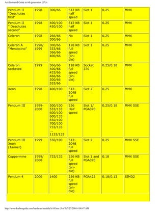
![An illustrated Guide to 6th generation CPUs
"Northwood" 2001 1600 512
full
speed
(on-
die)
PGA478 0.13 ?
"Tualatin" 2001 1500 512
full
speed
(on-
die)
Socket
370
0.13 ?
Celeron 2 2001 900 -
1200
128
full
speed
(on-
die)
Socket
370
0.13 ?
Three lines of Intel CPUs
[top]
If you study the scheme above, you see the development from Intel coming in three "lines".
Each line will be developed independently:
Market segment Processor line CPU speed Bus Speed/
Front Side Bus
speed
Number of CPUs
in system
The consumer
Socketed Celeron
566-1200 66/100 MHz 1
The professional
Pentium III
Pentium 4
733-1400
MHz
100/133 MHz
or 400 MHz
1 or 2
The server
Xeon
Tanner
(Cascades)
600 - 1200
MHz
100/133 MHz
or 400 MHz
4
q Next page
q Previous page
Learn more [top]
http://www.karbosguide.com/hardware/module3e10.htm (4 of 5)7/27/2004 4:08:47 AM](https://image.slidesharecdn.com/computerrepair-acompleteillustratedguidetopchardware-140318001250-phpapp01/85/Computer-repair-_a_complete_illustrated_guide_to_pc_hardware-455-320.jpg)
![An illustrated Guide to 6th generation CPUs
Read about drives in module 4a
Read about chip sets on the motherboard in module 2d
Read more about RAM in module 2e
Read module 5a about expansion cards, where we evaluate the I/O buses from the port side.
Read module 5b about AGP and module 5c about Firewire.
Read module 7a about monitors, and 7b on graphics card.
Read module 7c about sound cards, and 7d on digital sound and music.
[Main page] [Contact] [Karbo's Dictionary] [The Software Guides]
Copyright (c) 1996-2001 by Michael B. Karbo. www.karbosguide.com.
http://www.karbosguide.com/hardware/module3e10.htm (5 of 5)7/27/2004 4:08:47 AM](https://image.slidesharecdn.com/computerrepair-acompleteillustratedguidetopchardware-140318001250-phpapp01/85/Computer-repair-_a_complete_illustrated_guide_to_pc_hardware-456-320.jpg)
![A guide to Intel Itanium
Please click the banners to support our work!
KarbosGuide.com. Module 3e.11
A guide to Intel Itanium.
The contents:
q An introduction to Intel's Itanium/Merced
q The specs
q The perspective for IA 64
q Next page
q Previous page
The Itanium/Merced
[top]
Merced was the code name for a completely new CPU, which Intel has developed together
with HP, who has a vast experience in the manufacture of high end CPUs (RISC).The chip is
due 2000 and will be launched under the name Itanium.
The chippen will cost around $4000.
http://www.karbosguide.com/hardware/module3e11.htm (1 of 4)7/27/2004 4:08:53 AM](https://image.slidesharecdn.com/computerrepair-acompleteillustratedguidetopchardware-140318001250-phpapp01/85/Computer-repair-_a_complete_illustrated_guide_to_pc_hardware-457-320.jpg)
![A guide to Intel Itanium
There is no doubt that the Itanium is going to be a heavy processor. But it will not end up on
many desktops. It is too expensive, and the design is 100% intended the server market.
There have been speculations about a lousy IA-32 performance. All the programs we use
(including Windows 2000) are of 32bits design. This corresponds with the P6 processors (like
Pentium III etc.) which also are of 32 bits architecture.
Now Intel comes with a 64 bit processor. It has to emulate the 32 bit instructions, to execute
32 bit programs like Windows . An emulation is costly, it takes power from the processor.
This is also the case with the Itanium; it has to translate each of the IA-32 instruction. Some
magazines have claimed that the Itanium will be terrible slow executing IA-32 programs.
Some articles even claim that Intel wants to dump the Itanium and go for the successor
'McKinley'.
Anyway, the Itanium will require a new 64 bit operating system - could it be Windows 2064?
Linux 64 and NT 64 should be upcoming.
q Next page
q Previous page
Learn more [top]
Read about drives in module 4a
Read about chip sets on the motherboard in module 2d
Read more about RAM in module 2e
Read module 5a about expansion cards, where we evaluate the I/O buses from the port side.
Read module 5b about AGP and module 5c about Firewire.
Read module 7a about monitors, and 7b on graphics card.
Read module 7c about sound cards, and 7d on digital sound and music.
[Main page] [Contact] [Karbo's Dictionary] [The Software Guides]
http://www.karbosguide.com/hardware/module3e11.htm (3 of 4)7/27/2004 4:08:53 AM](https://image.slidesharecdn.com/computerrepair-acompleteillustratedguidetopchardware-140318001250-phpapp01/85/Computer-repair-_a_complete_illustrated_guide_to_pc_hardware-459-320.jpg)
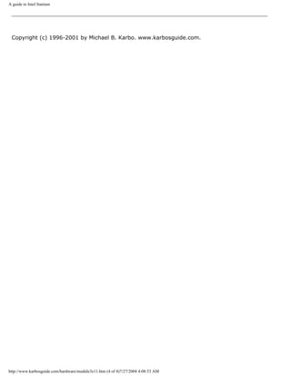
![An illustrated Guide VIA "Joshua" processor
Please click the banners to support our work!
KarbosGuide.com. Module 3e.12
The VIA "Joshua" processor
The contents:
q An introduction
q Compared to Athlon
q Next page
q Previous page
Joshua or Cyrix MIII [top]
Please support our
sponsor.
Cyrix was working on a brand new processor nucleus (code name Jalapeño) before the
http://www.karbosguide.com/hardware/module3e12.htm (1 of 3)7/27/2004 4:08:55 AM](https://image.slidesharecdn.com/computerrepair-acompleteillustratedguidetopchardware-140318001250-phpapp01/85/Computer-repair-_a_complete_illustrated_guide_to_pc_hardware-461-320.jpg)
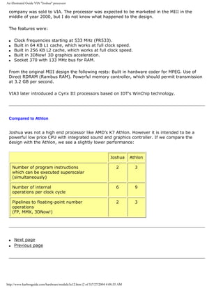
![An illustrated Guide VIA "Joshua" processor
Learn more [top]
Read about chip sets on the motherboard in module 2d
Read more about RAM in module 2e
Read module 5a about expansion cards, where we evaluate the I/O buses from the port side.
Read module 5b about AGP and module 5c about Firewire.
Read module 7a about monitors, and 7b on graphics card.
Read module 7c about sound cards, and 7d on digital sound and music.
[Main page] [Contact] [Karbo's Dictionary] [The Software Guides]
Copyright (c) 1996-2001 by Michael B. Karbo. www.karbosguide.com.
http://www.karbosguide.com/hardware/module3e12.htm (3 of 3)7/27/2004 4:08:55 AM](https://image.slidesharecdn.com/computerrepair-acompleteillustratedguidetopchardware-140318001250-phpapp01/85/Computer-repair-_a_complete_illustrated_guide_to_pc_hardware-463-320.jpg)
![An illustrated Guide AMD "Duron" processor
Please click the banners to support our work!
KarbosGuide.com. Module 3e.13
The AMD "Duron" processor
The contents:
q An introduction
q Compared to Celeron
q Next page
q Previous page
The Duron [top]
Please support our
sponsor.
In the summer 2000 AMD introduced a new and very powerful low-end chip, formerly known
as codename "Spitfire".
http://www.karbosguide.com/hardware/module3e13.htm (1 of 3)7/27/2004 4:08:56 AM](https://image.slidesharecdn.com/computerrepair-acompleteillustratedguidetopchardware-140318001250-phpapp01/85/Computer-repair-_a_complete_illustrated_guide_to_pc_hardware-464-320.jpg)
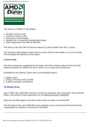
![An illustrated Guide AMD "Duron" processor
q Next page
q Previous page
Learn more [top]
Read about chip sets on the motherboard in module 2d
Read more about RAM in module 2e
Read module 5a about expansion cards, where we evaluate the I/O buses from the port side.
Read module 5b about AGP and module 5c about Firewire.
Read module 7a about monitors, and 7b on graphics card.
Read module 7c about sound cards, and 7d on digital sound and music.
[Main page] [Contact] [Karbo's Dictionary] [The Software Guides]
Copyright (c) 1996-2001 by Michael B. Karbo. www.karbosguide.com.
http://www.karbosguide.com/hardware/module3e13.htm (3 of 3)7/27/2004 4:08:56 AM](https://image.slidesharecdn.com/computerrepair-acompleteillustratedguidetopchardware-140318001250-phpapp01/85/Computer-repair-_a_complete_illustrated_guide_to_pc_hardware-466-320.jpg)
![An illustrated Guide Intel Pentium 4 processors
KarbosGuide.com. Module 3e.14
The Intel Pentium 4 processor
The contents:
q An introduction til Pentium 4
q SSE2
q The Execution Trace Cache
q "Northwood"
q Next page
q Previous
page
The Pentium 4 [top]
Please support our
sponsor.
In November 2000 Intel introduced the new and very powerful high-end chip Pentium 4, formerly known as codename
"Willamette". It was (as expected) delayed.
http://www.karbosguide.com/hardware/module3e14.htm (1 of 7)7/27/2004 4:08:59 AM](https://image.slidesharecdn.com/computerrepair-acompleteillustratedguidetopchardware-140318001250-phpapp01/85/Computer-repair-_a_complete_illustrated_guide_to_pc_hardware-467-320.jpg)
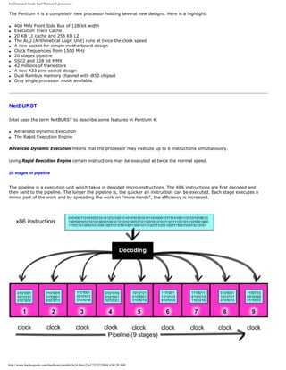
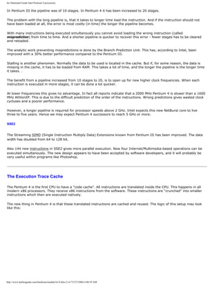
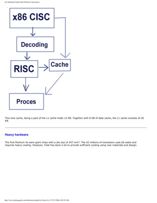
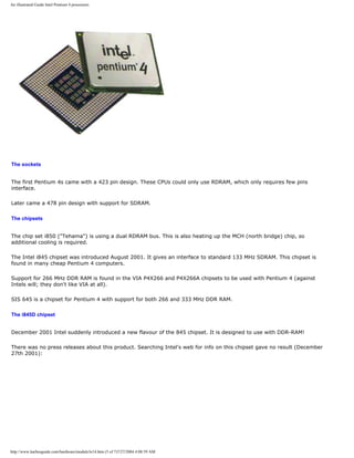
![An illustrated Guide Intel Pentium 4 processors
Learn more [top]
Read about chip sets on the motherboard in module 2d
Read more about RAM in module 2e
Read module 5a about expansion cards, where we evaluate the I/O buses from the port side.
Read module 5b about AGP and module 5c about Firewire.
Read module 7a about monitors, and 7b on graphics card.
Read module 7c about sound cards, and 7d on digital sound and music.
[Main page] [Contact] [Karbo's Dictionary] [The Software Guides]
Copyright (c) 1996-2001 by Michael B. Karbo. Click & Learn
http://www.karbosguide.com/hardware/module3e14.htm (7 of 7)7/27/2004 4:08:59 AM](https://image.slidesharecdn.com/computerrepair-acompleteillustratedguidetopchardware-140318001250-phpapp01/85/Computer-repair-_a_complete_illustrated_guide_to_pc_hardware-473-320.jpg)
![An illustrated Guide to disk drives - storage media.
Please click the banners to support our work!
KarbosGuide.com. Module 4a.
Drives are storage media
q Next page
q Previous page
A drive is the name for several types of storage media. There are also storage media, which
are not drives (RAM, Tape Streamers), but on these pages, we will discuss the drives.
Common to drive medium is:
q A file system can be assigned to them.
q They are recognized by the operating system and they are assigned a drive letter.
During start up, drives are typically recognized by the PC system software (ROM BIOS +
operating system). Thus, the PC knows which drives are installed. At the end of this
configuration, the appropriate drive letter is identified with each drive. If a drive is not "seen"
during start up, it will not be accessible to the operating system. However, some external
drives contain special soft-ware, allowing them to be connected during operation.
Some examples of drives
[top]
Storage media Drive letter
Floppy disks A: B:
Hard disk C: D: E:
CDROM/DVD F:
MO drive G:
http://www.karbosguide.com/hardware/module4a.htm (1 of 5)7/27/2004 4:09:00 AM](https://image.slidesharecdn.com/computerrepair-acompleteillustratedguidetopchardware-140318001250-phpapp01/85/Computer-repair-_a_complete_illustrated_guide_to_pc_hardware-474-320.jpg)
![An illustrated Guide to disk drives - storage media.
Network drive M:
RAM disk O:
On this and the following pages, I will describe the various drive types, their history and
technology. The last two drive types in the above table will not be covered.
Storage principles
[top]
Storage: Magnetic or optic. Data on any drive are digitized. That means that they are
expressed as myriads of 0s and 1s. However, the storage of these bits is done in any of three
principles:
The physical
drive principle
Disk types
Magnetic Floppy disks
Hard disk
Syquest disks
Zip drive
LS-120 disks
Optic CD-ROM
DVD
Magneto optic High end drives
Interface
[top]
Individual drives are connected to other PC components through an interface. The hard disk
interface is either IDE or SCSI, which in modern PCs is connected to the PCI bus. Certain
drives can also be connected through a parallel port or the floppy controller:
Interface Drive
IDE and EIDE Hard disks (currently up to 40 GB)
CD-ROM
SCSI Hard disks (all sizes) and CD-ROM
http://www.karbosguide.com/hardware/module4a.htm (2 of 5)7/27/2004 4:09:00 AM](https://image.slidesharecdn.com/computerrepair-acompleteillustratedguidetopchardware-140318001250-phpapp01/85/Computer-repair-_a_complete_illustrated_guide_to_pc_hardware-475-320.jpg)
![An illustrated Guide to disk drives - storage media.
ISA (internal) Floppy drives
CDROM and super floppies connected through parallel port
Let us start evaluating the drives from the easy side:
The traditional floppy drive
[top]
We all know diskettes. Small flat disks, irritatingly slow and with too limited storage capacity.
Yet, we cannot live without them. Very few PCs are without a floppy drive.
Diskettes were developed as a low cost alternative to hard disks. In the 60s and 70s, when
hard disk prices were exorbitant, It was unthinkable to use them in anything but mainframe
and mini computers.
The first diskettes were introduced in 1971. They were 8" diameter plastic disks with a
magnetic coating, enclosed in a cardboard case. They had a capacity of one megabyte. The
diskettes are placed in a drive, which has read and write heads. Conversely to hard disks, the
heads actually touch the disk, like in a cassette or video player. This wears the media.
Later, in 1976, 5.25" diskettes were introduced. They had far less capacity (only 160 KB to
begin with). However, they were inexpensive and easy to work with. For many years, they
were the standard in PCs. Like the 8" diskettes, the 5.25" were soft and flexible. Therefore,
they were named floppy disks.
In 1987 IBM's revolutionary PS/2 PCs were introduced and with them the 3½" hard diskettes
we know today. These diskettes have a thinner magnetic coating, allowing more tracks on a
smaller surface. The track density is measured in TPI (tracks per inch). The TPI has been
increased from 48 to 96 and now 135 in the 3.5" diskettes.
Here you see the standard PC diskette configurations:
Diskette size Name Tracks per side Number of sectors
per tracks
Capacity
5.25" Single side SD8 40 8 40 X 8 X 512 bytes
= 160 KB
5.25" Double side DD9 40 9 2 X 40 X 9 X 512
bytes = 360 KB
5.25" Double side
High Density
DQ15 80 15 2 X 80 X 15 X 512
bytes = 1.2 MB
3.5" DD DQ9 80 9 2 X 80 X 9 X 512
bytes = 720 KB
http://www.karbosguide.com/hardware/module4a.htm (3 of 5)7/27/2004 4:09:00 AM](https://image.slidesharecdn.com/computerrepair-acompleteillustratedguidetopchardware-140318001250-phpapp01/85/Computer-repair-_a_complete_illustrated_guide_to_pc_hardware-476-320.jpg)
![An illustrated Guide to disk drives - storage media.
3.5" HD DQ18 80 18 2 X 80 X 18 X 512
bytes = 1.44 MB
3.5" XD ( IBM only) DG36 80 36 2 X 80 X 36 X 512
bytes = 2.88 MB
Diskette drives turn at 300 RPM. That results in an average search time (½ revolution) of 100
ms.
The super floppy drives are described in module 4d.
The floppy controller
[top]
All diskette drives are governed by a controller. The original PC controller was named NEC
PD765. Today, it is included in the chip set, but functions like a 765. It is a programmable
chip. It can be programmed to handle all the various floppy drive types: 5.25" or 3.5" drives,
DD or HD etc.
The controller has to be programmed at each start up. It must be told which drives to
control. This programming is performed by the start up programs in ROM (read module 2a).
So you don't have to identify available drive types at each start up, these drive parameters
are saved in CMOS RAM.
The floppy controller reads data from the diskette media in serial mode (one bit at a time.
like from hard disks). Data are delivered in parallel mode (16 bits at a time) to RAM via a
DMA channel. Thus, the drives should be able to operate without CPU supervision. However,
in reality this does not always work. Data transfer from a diskette drive can delay and
sometimes freeze the whole PC, so no other operations can be performed simultaneously.
q Next page
q Previous page
Learn more [top]
Module 4b about hard disks.
http://www.karbosguide.com/hardware/module4a.htm (4 of 5)7/27/2004 4:09:00 AM](https://image.slidesharecdn.com/computerrepair-acompleteillustratedguidetopchardware-140318001250-phpapp01/85/Computer-repair-_a_complete_illustrated_guide_to_pc_hardware-477-320.jpg)
![An illustrated Guide to disk drives - storage media.
Read Module 4c about optical media (CDROM and DVD).
Read Module 4d about super diskette and MO drives.
Read Module 4e about tape streamers (which are not drives).
Read Module 5c about SCSI.
Read Module 6a about file systems.
[Main page] [Contact] [Karbo's Dictionary] [The Software Guides]
Copyright (c) 1996-2001 by Michael B. Karbo. www.karbosguide.com.
http://www.karbosguide.com/hardware/module4a.htm (5 of 5)7/27/2004 4:09:00 AM](https://image.slidesharecdn.com/computerrepair-acompleteillustratedguidetopchardware-140318001250-phpapp01/85/Computer-repair-_a_complete_illustrated_guide_to_pc_hardware-478-320.jpg)
![An illustrated Guide toZip, LS120, HiFD and MO-drives
Iomega Zip 100 MB 10 million sold units makes it the most
compatible drive
LS120 120 MB Read and write on 1.44 MB floppies as well
Sony HiFD 200 MB Read and write on 1.44 MB floppies as well
Use the Zip, the LS120 or the HiFD in new PCs - they are cheap and good for backup. You also
find portable PC Card versions of these drives.
The Zip drive
[top]
The Zip drive uses a kind of diskette, which can hold 100 MB. In my opinion, the Zip drive
works excellently. They are stable, inexpensive, and easy to work with. The drives are not the
fastest.
I and many others have used Zip drives since they came on the market. This provides us with
a common standard to move large files and to make back-ups. For example, you can use this
drive to install Windows 95/98 on a computer without a CDROM and avoid having to insert
numerous floppy disks.
http://www.karbosguide.com/hardware/module4d.htm (2 of 8)7/27/2004 4:09:03 AM](https://image.slidesharecdn.com/computerrepair-acompleteillustratedguidetopchardware-140318001250-phpapp01/85/Computer-repair-_a_complete_illustrated_guide_to_pc_hardware-480-320.jpg)
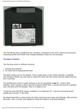
![An illustrated Guide toZip, LS120, HiFD and MO-drives
The BIOS manufacturers AMI and Phoenix include the floppy version of the drive in their
programs as a boot device. That will eliminate the need for other drivers, and you will be able
to boot from the Zip disk.
LS120
[top]
Since 1993, we have heard about the LS120 drive and now it is available. It is a 120 MB
standard designed by the company Imation. LS120 is supposed to replace the regular floppy
drives. At the same time, they read the traditional 3½" floppy diskettes (DD and HD) much
faster than the ordinary floppy drives.
The LS120 ought to have become the new floppy standard, but it has come too late with all the
installed Zip drives.
The drives, coming from Imation, use EIDE interface, and they are comparable to the Zip
drives.
However the SCSI-version of Zip is several times faster than the LS120 drive.
HiFD
[top]
Sony has a super diskette drive called HiFD (High Floppy Disk) holding 200 MB on a 3½" floppy
disk.
http://www.karbosguide.com/hardware/module4d.htm (4 of 8)7/27/2004 4:09:03 AM](https://image.slidesharecdn.com/computerrepair-acompleteillustratedguidetopchardware-140318001250-phpapp01/85/Computer-repair-_a_complete_illustrated_guide_to_pc_hardware-482-320.jpg)
![An illustrated Guide toZip, LS120, HiFD and MO-drives
Like the LS120, the HiFD disk drives can read and write old 1.44 MB floppy disks in addition to
the new high density disks. However, it should be a lot faster than the LS120 drive.
q 3.6 MB/s maximum transfer rate (read)
q 1.2 MB/s maximum transfer rate (write)
q 3,600 rpm rotational speed with dual discrete gap head (flying head type) and a high speed
head actuator with VCM (voice coil motor)
q Recording Capacity: 200 MB (formatted), 240 MB (unformatted).
q Disk Diameter: 86 mm
q Track Density: 2822 TPI (111 t/mm)
The HiFD drive is the best performing of the three super floppies mentioned in this article.
However, compatibility is often more important than performance. In that case Zip is the
winner.
MO drives
[top]
Magnetic Optic drives represent an exciting technology. The medium is magnetic, yet very
different from a hard disk. You can only write to it, when it is heated to about 300 degrees
Celsius (The Curie point)
This heating is done with a laser beam. The advantage is that the laser beam can heat a very
minute area precisely. In this manner the rather unprecise magnetic head, can write in
extremely small spots. Thus, writing is done with a laser guided magnet. The laser beam reads
the media. It can detect the polarization of the micro magnets on the media.
MO disks are fast, inexpensive, and extremely stable. They are regarded as almost wear proof.
They can be written over and over again forever, without signs of wear. The data life span is
http://www.karbosguide.com/hardware/module4d.htm (5 of 8)7/27/2004 4:09:03 AM](https://image.slidesharecdn.com/computerrepair-acompleteillustratedguidetopchardware-140318001250-phpapp01/85/Computer-repair-_a_complete_illustrated_guide_to_pc_hardware-483-320.jpg)
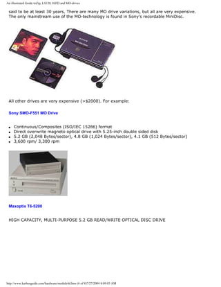
![An illustrated Guide toZip, LS120, HiFD and MO-drives
Near-field recording
A new magneto optical technology with flying heads and solid immersion optical lenses is called
near-field recording. It promises 20 GB high density magnetic storage on 5.25" plastic media.
Check www.terastor.com for further information.
q Next page
q Previous page
Learn more [top]
Module 4e about tape streamers (which not are drives).
Module 5c about the SCSI interface
Module 6a about the file systems.
[Main page] [Contact] [Karbo's Dictionary] [The Software Guides]
http://www.karbosguide.com/hardware/module4d.htm (7 of 8)7/27/2004 4:09:03 AM](https://image.slidesharecdn.com/computerrepair-acompleteillustratedguidetopchardware-140318001250-phpapp01/85/Computer-repair-_a_complete_illustrated_guide_to_pc_hardware-485-320.jpg)
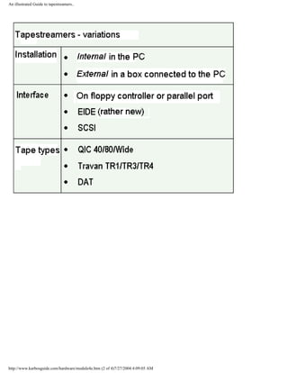
![An illustrated Guide to tapestreamers..
q Next page
q Previous page
Learn more [top]
Module 5a about adapters.
Read Module 5c about SCSI.
Read Module 6a about file systems.
Last revised: February 20, 1997.
[Main page] [Contact] [Karbo's Dictionary] [The Software Guides]
http://www.karbosguide.com/hardware/module4e.htm (3 of 4)7/27/2004 4:09:05 AM](https://image.slidesharecdn.com/computerrepair-acompleteillustratedguidetopchardware-140318001250-phpapp01/85/Computer-repair-_a_complete_illustrated_guide_to_pc_hardware-489-320.jpg)
![A Guide to Adapters and I/O units.
Please click the banners to support our work!
KarbosGuide.com. Module 5a1a.
About the PC I/O system. Expansion cards. Adapters, etc.
The contents:
q Intro to I/O
q A model
q Next page
q Previous page
Intro to I/O [top]
Please support our
sponsor.
This page should preferably be read together with module 2c, 2d, 5b and 5c. The first two describe the I/
O buses and the chip sets. Here we will look at the other end of the I/O buses, the "exit."
There are four I/O buses in the modern PC architecture and each of them has several functions. They
may lead to internal and external ports or they lead to other controlling buses. The four buses are:
http://www.karbosguide.com/hardware/module5a1a.htm (1 of 4)7/27/2004 4:09:06 AM](https://image.slidesharecdn.com/computerrepair-acompleteillustratedguidetopchardware-140318001250-phpapp01/85/Computer-repair-_a_complete_illustrated_guide_to_pc_hardware-491-320.jpg)
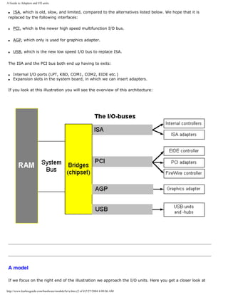
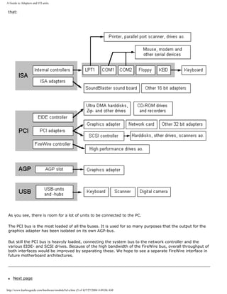
![A Guide to Adapters and I/O units.
q Previous page
Learn more [top]
Read: Module 5b about EIDE, Ultra DMA and AGP.
Read Module 5c about SCSI, USB etc.
Read A little about Windows 95/98.
Read Module 6c about the relationship between BIOS, OS and hardware
Read Module 7a about the videosystem
Read about video cards in Module 7b.
Read about digital sound in Module 7c.
[Main page] [Contact] [Karbo's Dictionary] [The Software Guides]
Copyright (c) 1996-2001 by Michael B. Karbo. www.karbosguide.com.
http://www.karbosguide.com/hardware/module5a1a.htm (4 of 4)7/27/2004 4:09:06 AM](https://image.slidesharecdn.com/computerrepair-acompleteillustratedguidetopchardware-140318001250-phpapp01/85/Computer-repair-_a_complete_illustrated_guide_to_pc_hardware-494-320.jpg)
![A Guide to Adapters and I/O units.
Please click the banners to support our work!
KarbosGuide.com. Module 5a1b.
About I/O units, continued
The contents:
q The Internal I/O ports and units
q The serial ports
q Next page
q Previous page
The internal I/O ports [top]
Please support our
sponsor.
As mentioned, the USB is going to become the main bus for low speed devices. But so far we still use the internal "face"
of the ISA bus for a range of purposes. At any PC motherboard you find these:
q The floppy controller
q The serial ports
q The parallel port(s)
q The keyboard controller
They all occupy IRQs which is a central part of ISA architecture and a pain in the a... Let us take a moment to look at
these ports and controllers.
http://www.karbosguide.com/hardware/module5a1b.htm (1 of 5)7/27/2004 4:09:08 AM](https://image.slidesharecdn.com/computerrepair-acompleteillustratedguidetopchardware-140318001250-phpapp01/85/Computer-repair-_a_complete_illustrated_guide_to_pc_hardware-495-320.jpg)
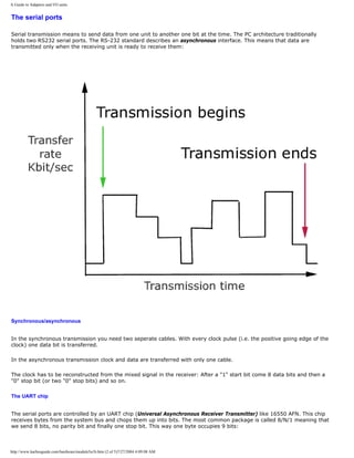
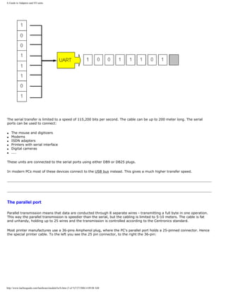
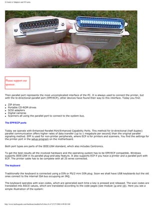
![A Guide to Adapters and I/O units.
This system is quite flexible because it allows for arbitrary remapping of the keyboard codes. This is especially useful if
you find the placement of the Caps Lock and Control keys awkward. It's a simple matter to remap them to swap places.
Each key generates a unique scan code. This happens completely independent of the typeface that is printed on the
plastic key.
At the other end, the code pages represents a programmable interpretation of the key press; you can assign any type to
any key as you want it. Languages like German and French use different keyboard layouts as well as many other
languages.
q Next page
q Previous page
Learn more [top]
Read: Module 5b about EIDE, Ultra DMA and AGP.
Read Module 5c about SCSI, USB etc.
Read A little about Windows 95/98.
Read Module 6c about the relationship between BIOS, OS and hardware
Read Module 7a about the videosystem
Read about video cards in Module 7b.
Read about digital sound in Module 7c.
[Main page] [Contact] [Karbo's Dictionary] [The Software Guides]
Copyright (c) 1996-2001 by Michael B. Karbo. www.karbosguide.com.
http://www.karbosguide.com/hardware/module5a1b.htm (5 of 5)7/27/2004 4:09:08 AM](https://image.slidesharecdn.com/computerrepair-acompleteillustratedguidetopchardware-140318001250-phpapp01/85/Computer-repair-_a_complete_illustrated_guide_to_pc_hardware-499-320.jpg)
![A Guide to Adapters and I/O units.
Adapters
In a stationary PC, adapters are typically printed circuit
boards called expansion boards or expansion cards. They
form a link between the central PC unit and various
peripherals. This is the so-called open architecture.
[top]
Please support our
sponsor.
q Typically, adapters provide functions, which are separated from the system board.
q Adapters provide expansion capability to the PC.
There are PCs without expansion slots. In that case all functions must be built into the
system board. You could easily include chips for graphics, ethernet, SCSI, and sound on the
system board. This is not common in stationary PCs. Portable, laptop PCs have nearly all
electronics on the system board. This is called closed architecture.
A traditional PC has a system board which contains all standard functions (except the
graphics chip). To this system board you can add various expansion cards, which control one
or more peripheral units:
The system board Expansion boards
Standard functions
incl. control of
keyboard,
COM and LPT ports. and
four EIDE units.
Video card
Network controller
Sound card
SCSI card
3D graphics controller (for 3D games)
Other expansion board types:
q Internal modem (in lieu of external modem)
q ISDN adapters
q Extra parallel ports
q Video editing boards
q Special graphics cards, which supplement the usual (3D and MPEG)
q TV and radio receivers.
http://www.karbosguide.com/hardware/module5a2.htm (2 of 6)7/27/2004 4:09:10 AM](https://image.slidesharecdn.com/computerrepair-acompleteillustratedguidetopchardware-140318001250-phpapp01/85/Computer-repair-_a_complete_illustrated_guide_to_pc_hardware-501-320.jpg)
![A Guide to Adapters and I/O units.
The integrated hard disk controller [top]
Please support our
sponsor.
In the Pentium based PC, the hard disk is connected to an EIDE controller, which is
integrated on the system board. Likewise, the serial and parallel ports are connected directly
to the system board. This is new. On the 386 PCs, you had to install special controller cards
(I/O cards) to handle these functions. They are included in the modern chip sets on the
system board. Other functions are not integrated. That includes:
The video controller
[top]
You have to install a video card to make the PC function. It would be illogical to assemble a
PC without a video card. You would not be able to see what you are doing, since the video
card governs data transmission to the monitor.
The advantage of this design is, that the user can choose between numerous video cards in
various qualities. A discount store may offer a complete Pentium based PC (without printer)
and with the cheapest video card for $669.-. If the buyer is quality oriented, he would want
to spend an additional $40 to get a much better video card.
The modular PC design
[top]
In this way, various expansion boards provide flexibility in assembling a customized PC. At
the same time, various electronics manufacturers are specializing their production:
ASUS and Tyan are good at making system boards. Others, like S3, Matrox, and ATI
specialize in making graphics chips and expansion boards. Olicom make only net boards.
Adaptec make only SCSI controllers and Creative Labs make SoundBlaster sound boards.
This variety of manufacturers offers the consumer wide choices. Your PC can be customized
and configured according to your needs and wallet size.
http://www.karbosguide.com/hardware/module5a2.htm (3 of 6)7/27/2004 4:09:10 AM](https://image.slidesharecdn.com/computerrepair-acompleteillustratedguidetopchardware-140318001250-phpapp01/85/Computer-repair-_a_complete_illustrated_guide_to_pc_hardware-502-320.jpg)
![A Guide to Adapters and I/O units.
About the electronics
[top]
The adapter is a printed circuit board. They have an edge connector, so they can be inserted
in expansion slots in the system board. The expansion slots connect to the I/O buses. Since
the Pentium system board has two I/O buses, it has two types of expansion slots:
q ISA slots
q PCI slots
Typically, on a regular Pentium system board there are three or four of each type. That gives
a total of 7 expansion slots. One expansion board can be installed in each of these. You
simply press the edge connector of the expansion board into the expansion slot. Now it is
connected to the bus.
Here you see two PCI slots open for video cards, network controllers and others:
Below, you see a network adapter. It is an ethernet card with PCI interface, so it fits in a PCI
slot in the Pentium. This inexpensive board allows your computer to join a network with other
net board equipped PCs. Please compare the edge connector at the button of the card with
the sockets above. They fit together!
http://www.karbosguide.com/hardware/module5a2.htm (4 of 6)7/27/2004 4:09:10 AM](https://image.slidesharecdn.com/computerrepair-acompleteillustratedguidetopchardware-140318001250-phpapp01/85/Computer-repair-_a_complete_illustrated_guide_to_pc_hardware-503-320.jpg)
![A Guide to Adapters and I/O units.
q Next page
q Previous page
Learn more [top]
Read: Module 5b about EIDE, Ultra DMA and AGP.
Read Module 5c about USB.
Read Module 6b with a little about Windows 95/98.
Read Module 6c about the relationship between BIOS, OS and hardware
Read Module 7a about the videosystem
http://www.karbosguide.com/hardware/module5a2.htm (5 of 6)7/27/2004 4:09:10 AM](https://image.slidesharecdn.com/computerrepair-acompleteillustratedguidetopchardware-140318001250-phpapp01/85/Computer-repair-_a_complete_illustrated_guide_to_pc_hardware-504-320.jpg)
![A Guide to Adapters and I/O units.
Read about video cards in Module 7b.
Read about digital sound in Module 7c.
[Main page] [Contact] [Karbo's Dictionary] [The Software Guides]
Copyright (c) 1996-2001 by Michael B. Karbo. www.karbosguide.com.
http://www.karbosguide.com/hardware/module5a2.htm (6 of 6)7/27/2004 4:09:10 AM](https://image.slidesharecdn.com/computerrepair-acompleteillustratedguidetopchardware-140318001250-phpapp01/85/Computer-repair-_a_complete_illustrated_guide_to_pc_hardware-505-320.jpg)
![A Guide to Adapters and I/O units.
Please click the banners to support our work!
KarbosGuide.com. Module 5a3.
About IRQs, DMA, bus mastering etc.
The contents:
q IRQ
q DMA
q Bus mastering
q Next page
q Previous page
IRQs
When you install an expansion board in a slot, it gets
connected to the I/O bus. Now the board can send and receive
data. But who regulates the traffic? Who gives clearance to the
new controller to send data? It would appear that data traffic
could soon be chaotic.
[top]
Please support our
sponsor.
To control data traffic on the I/O bus, the concept of IRQ (Interrupt ReQuest) was created.
Interrupts are a fundamental principle in the PC design. There are two types of interrupts: Software
Interrupts are used to call any number of BIOS routines. Hardware Interrupts are the subject of this
page.
Hardware Interrupts
[top]
http://www.karbosguide.com/hardware/module5a3.htm (1 of 9)7/27/2004 4:09:13 AM](https://image.slidesharecdn.com/computerrepair-acompleteillustratedguidetopchardware-140318001250-phpapp01/85/Computer-repair-_a_complete_illustrated_guide_to_pc_hardware-506-320.jpg)
![A Guide to Adapters and I/O units.
The adapter or unit on the I/O bus uses the interrupt to signal request to send or receive data. An
interrupt signal is like a door bell. The unit signals by applying a voltage to one of the wires in the
bus - an IRQ. When the CPU acknowledges the signal, it knows that the unit wants send or receive
data, or is finished.
The advantage of IRQs is that the CPU can manage other tasks, while an adapter "massages" its
data. When the adapter has finished its task, it will report to the CPU with a new IRQ.
As an example, let us see how keyboard data are handled. The keyboard send bits, serially, through
the cable to the keyboard controller. The controller organizes them in groups of 8 (one byte). Every
time it has a byte, it sends an IRQ to the I/O bus. The IRQ controller asks the CPU permission to
use the bus, to send the byte to wherever. The IRQ controller reports back to the keyboard
controller, giving clearance to send the next character (byte):
IRQ wires
[top]
Physically, the IRQ is a wire on the bus. This wire connects to all expansion slots. Therefore,
regardless of in which slot you install an adapter, the adapter can communicate with an IRQ.
http://www.karbosguide.com/hardware/module5a3.htm (2 of 9)7/27/2004 4:09:13 AM](https://image.slidesharecdn.com/computerrepair-acompleteillustratedguidetopchardware-140318001250-phpapp01/85/Computer-repair-_a_complete_illustrated_guide_to_pc_hardware-507-320.jpg)
![A Guide to Adapters and I/O units.
In the pristine PC design (the original PC/XT bus) you found 8 IRQ's. The more recent PC is "born"
with 16 IRQs, but five of them are internal, and cannot be used with I/O cards, and one of them
connects the lower IRQ's with the higher (IRQ2/9).
We find 10 accessible IRQs on the I/O buses. Each of those consist of a circuit board wire, which
goes through the entire bus. When you install an expansion card in a vacant slot, one of the IRQs is
assigned to it.
When a signal arrives on an IRQ channel, that is a message to the CPU. It is told that a unit wants
to get on the bus. Which unit is to be identified through the IRQ number.
Next the unit is admitted to the bus, to send or receive data. When the transaction is completed,
another signal is transmitted to the CPU to indicate that the bus is vacant.
The IRQs have different priorities, so the CPU knows which IRQ have priority, if two signals are sent
simultaneously.
The IRQ system is guided by a controller chip, like Intel 8259. It can handle 8 IRQ signals and
couple two of them together, via IRQ 2 or 9. All PCs with ISA bus include two 8259 chips.
MSD (Microsoft Diagnose System)
[top]
Let me show an image of the MSD diagnostic program, which you can run in Windows 95/98. It
shows the use of IRQs on a PC:
http://www.karbosguide.com/hardware/module5a3.htm (3 of 9)7/27/2004 4:09:13 AM](https://image.slidesharecdn.com/computerrepair-acompleteillustratedguidetopchardware-140318001250-phpapp01/85/Computer-repair-_a_complete_illustrated_guide_to_pc_hardware-508-320.jpg)
![A Guide to Adapters and I/O units.
MSD shows the IRQs of the PC, where the program is run. There are a total of 15 IRQ channels and
each IRQ is assigned to a unit. However, it is not always possible to utilize IRQ 9. It functions like a
bridge between two parts in the IRQ system.
In the above illustration, IRQ numbers 5, 10, 11, 12, and 15 appear vacant.
IRQ numbers 2 and 9 show the linking between those two IRQ controllers.
Some IRQs are reserved for various internal units, which must also be able to disconnect the CPU.
Those are IRQ numbers 0, 1, 2, 8, and 13, as you can see in the illustration above. They are not
available for other units. In principle, the remainder are available for expansion boards and EIDE
units.
IRQs are assigned during the PC start-up. An ISA expansion board is assigned a given IRQ during
start-up. That IRQ is used every time that expansion board uses the bus.
Shared IRQs
The modern I/O buses MCA, EISA and PCI permit shared IRQs. Thus, two adapters can share one
IRQ. When the IRQ is activated, the drive programs for the two adapters are checked, to identify
which is on the bus.
IRQ and conflicts on the ISA bus
[top]
http://www.karbosguide.com/hardware/module5a3.htm (4 of 9)7/27/2004 4:09:13 AM](https://image.slidesharecdn.com/computerrepair-acompleteillustratedguidetopchardware-140318001250-phpapp01/85/Computer-repair-_a_complete_illustrated_guide_to_pc_hardware-509-320.jpg)
![A Guide to Adapters and I/O units.
DMA
[top]
IRQs are only one of the problems with ISA boards. The other one is DMA (Direct Memory Access).
That is a system which allows an adapter to transfer data to RAM without CPU involvement.
http://www.karbosguide.com/hardware/module5a3.htm (6 of 9)7/27/2004 4:09:13 AM](https://image.slidesharecdn.com/computerrepair-acompleteillustratedguidetopchardware-140318001250-phpapp01/85/Computer-repair-_a_complete_illustrated_guide_to_pc_hardware-511-320.jpg)
![A Guide to Adapters and I/O units.
Normally, the CPU controls all bus activities. With DMA, this "intelligence" is assigned to a DMA
controller on the system board. This special controller chip (Intel 8237) has clearance to move data
to and from RAM, via the I/O bus, without burdening the CPU.
You can implement a number of DMA channels, which can be used by the ISA boards. Each channel
has its own number and one controller can be in charge of four channels. Each ISA unit can occupy
one of these channels, if so designed. Diskette drives utilize DMA.
The DMA system can result in conflicts between two units on the bus, if they have requested the
same DMA channel. As an example, on ISA sound boards you have to reset both IRQ and DMA
number.
It is important to enable DMA for your harddisk in Windows . See how in this Windows tip.
Bus mastering
[top]
There are no DMA channels on the PCI bus. Instead bus mastering is employed. It is a similar
system, where special controller functions allow adapters to control the bus. Thus, they can deliver
their data directly to RAM, minimizing the workload on the CPU. It does not need to keep track of
the transactions, the bus master takes care of that.
http://www.karbosguide.com/hardware/module5a3.htm (7 of 9)7/27/2004 4:09:13 AM](https://image.slidesharecdn.com/computerrepair-acompleteillustratedguidetopchardware-140318001250-phpapp01/85/Computer-repair-_a_complete_illustrated_guide_to_pc_hardware-512-320.jpg)
![A Guide to Adapters and I/O units.
This allows the PC to multitask, handle more than one task at a time. The hard disk can pour
streams of data to RAM, while the CPU handles some other task. The bus mastering system works
fairly well with EIDE hard disks. However in this particular area, the SCSI controller is far more
advanced. EIDE bus mastering is rather new and we will see further developments in this area.
Bus mastering version Chip set Year
DMA mode 2 82430FX 1995
Ultra DMA 82430TX 1997
The latest version Ultra DMA/66 is described in module 5b.
q Next page
q Previous page
Learn more [top]
Read: Module 5b about EIDE, Ultra DMA and AGP.
Read Module 5c about SCSI, USB etc.
Read Module 6b with a little about Windows 95/98.
Read Module 6c about the relationship between BIOS, OS and hardware
Read Module 7a about the videosystem
http://www.karbosguide.com/hardware/module5a3.htm (8 of 9)7/27/2004 4:09:13 AM](https://image.slidesharecdn.com/computerrepair-acompleteillustratedguidetopchardware-140318001250-phpapp01/85/Computer-repair-_a_complete_illustrated_guide_to_pc_hardware-513-320.jpg)
![A Guide to Adapters and I/O units.
Read about video cards in Module 7b.
Read about digital sound in Module 7c.
[Main page] [Contact] [Karbo's Dictionary] [The Software Guides]
Copyright (c) 1996-2001 by Michael B. Karbo. www.karbosguide.com.
http://www.karbosguide.com/hardware/module5a3.htm (9 of 9)7/27/2004 4:09:13 AM](https://image.slidesharecdn.com/computerrepair-acompleteillustratedguidetopchardware-140318001250-phpapp01/85/Computer-repair-_a_complete_illustrated_guide_to_pc_hardware-514-320.jpg)
![A Guide to Adapters and I/O units.
Please click the banners to support our work!
KarbosGuide.com. Module 5a4.
About I/O port, Plug and Play, and PC Cards.
The contents:
q I/O addressing
q Plug and Play (PnP)
q The physical connector on adapters
q Next page
q Previous page
I/O addresses
Finally, we need to mention how the CPU finds all these units - adapters, ports.
etc. They all have an address - an I/O port number.
Each unit can be reached through one of many I/O ports. Each port is a byte
port. That means that 8 bits (one byte) can be transmitted simultaneously -
parallel mode.
[top]
Please support our
sponsor.
If the unit is on the ISA bus, it handles 16 bits at a time (words). Then you link two consecutive ports together, to
make a 16 bit channel. If we talk about a 32 bit PCI unit, we link four byte ports together to get 32 bits width
(called dword).
The PC has a built in listing of all I/O units, each of which has their own "zip code" - a port address. Since the PC is
basically a 16 bit computer, there are 2 at the 16th power possible addresses (65,536) - from 0000 to FFFFH. They
are described in the hexadecimal number system as 5 digit numbers. Hexadecimal is a 16 digit number system.
Digits go from 0 to 9 and continue with 6 letters A - F. Let me show you some examples of I/O addresses:
Unit I/O ports
CMOS RAM 0070H
Keyboard 0060H ... 0063H
Serial port 1 (COM 1) 03F8H ... 03FFH
Parallel port 1 (LPT1) 0378H ... 037FH
http://www.karbosguide.com/hardware/module5a4.htm (1 of 3)7/27/2004 4:09:14 AM](https://image.slidesharecdn.com/computerrepair-acompleteillustratedguidetopchardware-140318001250-phpapp01/85/Computer-repair-_a_complete_illustrated_guide_to_pc_hardware-515-320.jpg)
![A Guide to Adapters and I/O units.
Fortunately, you do not have to adjust port addresses too often. Some adapters give room to adjust to user option I/
O addresses, but you have to have bad luck to encounter any conflict in this area.
Plug and Play
[top]
Plug and play (PnP) is an industry standard for expansion boards. If the board conforms to the PnP standard, the
installation is very simple. The board configures itself automatically. These are the minimum requirements:
q The PC system board must be PnP compatible.
q The operating system must be capable of utilizing PnP, as Windows is.
q The adapter must be able to inform the I/O bus which I/O addresses and IRQs it can communicate with.
q The adapter must be able to adjust to use the I/O address and the IRQ, which the I/O bus communicates to the
adapter.
The physical connector
[top]
The different I/O cards each fit with a particular I/O bus. The different buses each have their own system board slot
configuration. That is a socket in the system board, in which you press in the expansion board. Here you see three
different edge connectors fitting into each their own type of socket. The ISA bus has a total of 98 prongs (31+18 on
each side).
http://www.karbosguide.com/hardware/module5a4.htm (2 of 3)7/27/2004 4:09:14 AM](https://image.slidesharecdn.com/computerrepair-acompleteillustratedguidetopchardware-140318001250-phpapp01/85/Computer-repair-_a_complete_illustrated_guide_to_pc_hardware-516-320.jpg)
![A Guide to Adapters and I/O units.
q Next page
q Previous page
Learn more [top]
Module 5b about EIDE, Ultra DMA and AGP.
Read Module 5c about SCSI, USB etc.
Read Module 6b with a little about Windows 95/98.
Read Module 6c about the relationship between BIOS, OS and hardware
Read Module 7a about the videosystem
Read about video cards in Module 7b.
Read about digital sound in Module 7c.
[Main page] [Contact] [Karbo's Dictionary] [The Software Guides]
Copyright (c) 1996-2001 by Michael B. Karbo. www.karbosguide.com.
http://www.karbosguide.com/hardware/module5a4.htm (3 of 3)7/27/2004 4:09:14 AM](https://image.slidesharecdn.com/computerrepair-acompleteillustratedguidetopchardware-140318001250-phpapp01/85/Computer-repair-_a_complete_illustrated_guide_to_pc_hardware-517-320.jpg)
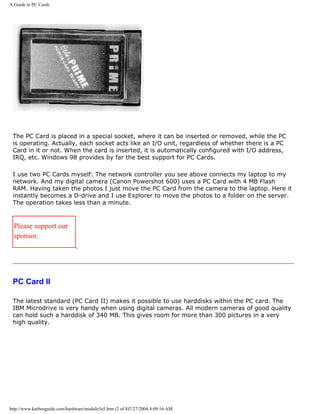
![A Guide to PC Cards
The PC card, holding Compact Flash Card, SSFDC (SmartMedia) or a MicroDrive, can be read
by a USB-connected reader like these:
If you use PC Card, you should invest in a reader for USB. It is very handy and speedy.
CardX
The new high speed serial ports USB and FireWire will also become available for portable PC
users. CardX is a new PC Card interface built on FireWire and allowing transfers of up to 400
megabit per second.
Two function adapters
[top]
http://www.karbosguide.com/hardware/module5a5.htm (3 of 4)7/27/2004 4:09:16 AM](https://image.slidesharecdn.com/computerrepair-acompleteillustratedguidetopchardware-140318001250-phpapp01/85/Computer-repair-_a_complete_illustrated_guide_to_pc_hardware-520-320.jpg)
![A Guide to PC Cards
Integrated adapters with more than one function are space savers. Especially, the ASUS
company has introduced dual function boards to stationary PCs, since they utilize both the
ISA and PCI bus to share a slot:
q Graphics + sound
q SCSI + sound There are also two function PC Cards for portable PCs:
q Ethernet network controller + modem
q Token Ring network controller + modem
q Next page
q Previous page
Learn more [top]
Module 5b about EIDE, Ultra DMA and AGP.
Read Module 5c about SCSI, USB etc.
Read Module 6b with a little about Windows 95/98.
Read Module 6c about the relationship between BIOS, OS and hardware
Read Module 7a about the videosystem
Read about video cards in Module 7b.
Read about digital sound in Module 7c.
[Main page] [Contact] [Karbo's Dictionary] [The Software Guides]
Copyright (c) 1996-2001 by Michael B. Karbo. www.karbosguide.com.
http://www.karbosguide.com/hardware/module5a5.htm (4 of 4)7/27/2004 4:09:16 AM](https://image.slidesharecdn.com/computerrepair-acompleteillustratedguidetopchardware-140318001250-phpapp01/85/Computer-repair-_a_complete_illustrated_guide_to_pc_hardware-521-320.jpg)
![An easy-read and illustrated Guide to the EIDE, Ultra DMA and AGP interfaces. For teachers, students and self-study.
Please click the banners to support our work!
KarbosGuide.com. Module 5b1.
About the interfaces EIDE, Ultra DMA and AGP
The contents:
q What is EIDE?
q Four units controlled by the motherboard
On the following pages:
q The EIDE cable
q The Promise FastTrack EIDE controller
q Transfer speeds and protocols
q What does Ultra DMA offer?
q Looking at a good harddisk
q ATA/66
q Configuring your EIDE hard disk
q What is AGP?
q Next page
q Previous page
What is EIDE? [top]
Please support our
sponsor.
EIDE is the current standard for inexpensive, high performance hard disks used in PCs.
EIDE stands for Enhanced IDE and it is registered name own by harddisk manufacture
Western Digital. They also own the name "IDE".
Other companies like Seagate, IBM, Quantum and Maxtor Uses the term ATA, which stands
http://www.karbosguide.com/hardware/module5b1.htm (1 of 4)7/27/2004 4:09:18 AM](https://image.slidesharecdn.com/computerrepair-acompleteillustratedguidetopchardware-140318001250-phpapp01/85/Computer-repair-_a_complete_illustrated_guide_to_pc_hardware-522-320.jpg)
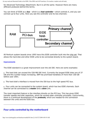
![An easy-read and illustrated Guide to the EIDE, Ultra DMA and AGP interfaces. For teachers, students and self-study.
The EIDE interface is not designed for hard disks only. There are four channels, which can be
connected to four independent units:
q Hard disks
q CD-ROM drives
q CR-RW drives
q DVD drives
q LS 120, Zip or HiFD drive
q Tape streamers
EIDE is thus designed as an inexpensive all-round interface, which can be connected to all
kinds of storage media.
Auto detect
The BIOS on the system board has a neat auto detect feature, which often allows EIDE units
to be connected directly and work immediately. The PC start up program automatically finds
the necessary information about the drive via the auto detect function.
Sometimes you have to assist the hard disk installation by activating the auto detect in the
CMOS Setup program, but often it runs by itself. You definitely do not have to key in
information about cylinders, etc., as you had to with earlier IDE units.
q Next page
q Previous page
To learn more
[top]
Read more the boot process and system bus in Module 2b
Read about file systems in module 6a
Read about I/O buses in module 2c
Read about the motherboard chip set in module 2d
Read about RAM in module 2e
Read Module 5c about SCSI, USB etc.
http://www.karbosguide.com/hardware/module5b1.htm (3 of 4)7/27/2004 4:09:18 AM](https://image.slidesharecdn.com/computerrepair-acompleteillustratedguidetopchardware-140318001250-phpapp01/85/Computer-repair-_a_complete_illustrated_guide_to_pc_hardware-524-320.jpg)
![An easy-read and illustrated Guide to the EIDE, Ultra DMA and AGP interfaces. For teachers, students and self-study.
Read module 7a about monitors, and 7b on graphics card.
Click for Module 7d about digital music, MP3s
[Main page] [Contact] [Karbo's Dictionary] [The Software Guides]
Copyright (c) 1996-2001 by Michael B. Karbo. www.karbosguide.com.
http://www.karbosguide.com/hardware/module5b1.htm (4 of 4)7/27/2004 4:09:18 AM](https://image.slidesharecdn.com/computerrepair-acompleteillustratedguidetopchardware-140318001250-phpapp01/85/Computer-repair-_a_complete_illustrated_guide_to_pc_hardware-525-320.jpg)
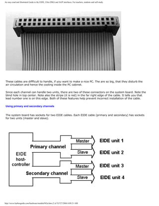
![An easy-read and illustrated Guide to the EIDE, Ultra DMA and AGP interfaces. For teachers, students and self-study.
So for best performance, the two harddisk have to be assigned one at the primary EIDE channel and the
other at the secondary EIDE channel. This leaves us with the problem of the CD-ROM drives, which also
have to be placed on EIDE channels.
My conclusion is that if you have to use two EIDE harddisks (and many of us do), the motherboard should
be enhanced with further EIDE channels. Please continue the reading...
q Next page
q Previous page
To learn more
[top]
Read more the boot process and system bus in Module 2b
http://www.karbosguide.com/hardware/module5b2a.htm (4 of 5)7/27/2004 4:09:21 AM](https://image.slidesharecdn.com/computerrepair-acompleteillustratedguidetopchardware-140318001250-phpapp01/85/Computer-repair-_a_complete_illustrated_guide_to_pc_hardware-529-320.jpg)
![An easy-read and illustrated Guide to the EIDE, Ultra DMA and AGP interfaces. For teachers, students and self-study.
Read about file systems in module 6a
Read about I/O buses in module 2c
Read about the motherboard chip set in module 2d
Read about RAM in module 2e
Read Module 5c about SCSI, USB etc.
Read module 7a about monitors, and 7b on graphics card.
[Main page] [Contact] [Karbo's Dictionary] [The Software Guides]
Copyright (c) 1996-2001 by Michael B. Karbo. www.karbosguide.com.
http://www.karbosguide.com/hardware/module5b2a.htm (5 of 5)7/27/2004 4:09:21 AM](https://image.slidesharecdn.com/computerrepair-acompleteillustratedguidetopchardware-140318001250-phpapp01/85/Computer-repair-_a_complete_illustrated_guide_to_pc_hardware-530-320.jpg)
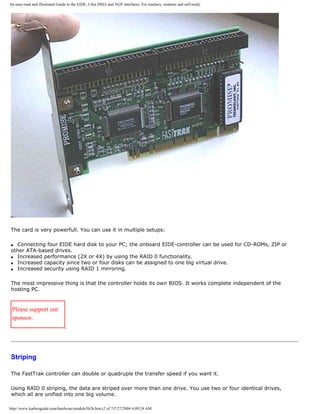
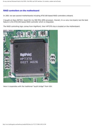
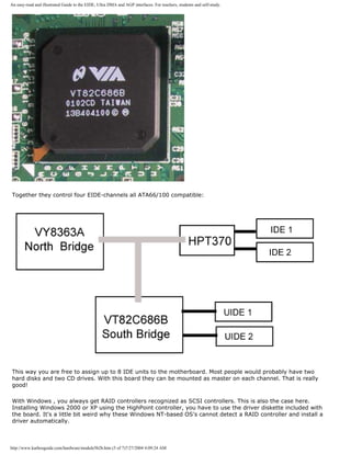
![An easy-read and illustrated Guide to the EIDE, Ultra DMA and AGP interfaces. For teachers, students and self-study.
However the driver installation works perfectly. You see the controller under SCSI/RAID controllers:
q Next page
q Previous page
To learn more
[top]
Read more the boot process and system bus in Module 2b
Read about file systems in module 6a
Read about I/O buses in module 2c
Read about the motherboard chip set in module 2d
Read about RAM in module 2e
http://www.karbosguide.com/hardware/module5b2b.htm (6 of 7)7/27/2004 4:09:24 AM](https://image.slidesharecdn.com/computerrepair-acompleteillustratedguidetopchardware-140318001250-phpapp01/85/Computer-repair-_a_complete_illustrated_guide_to_pc_hardware-536-320.jpg)
![An easy-read and illustrated Guide to the EIDE, Ultra DMA and AGP interfaces. For teachers, students and self-study.
Read Module 5c about SCSI, USB etc.
Read module 7a about monitors, and 7b on graphics card.
[Main page] [Contact] [Karbo's Dictionary] [The Software Guides]
Copyright (c) 1996-2001 by Michael B. Karbo. www.karbosguide.com.
http://www.karbosguide.com/hardware/module5b2b.htm (7 of 7)7/27/2004 4:09:24 AM](https://image.slidesharecdn.com/computerrepair-acompleteillustratedguidetopchardware-140318001250-phpapp01/85/Computer-repair-_a_complete_illustrated_guide_to_pc_hardware-537-320.jpg)
![An easy-read and illustrated Guide to the EIDE, Ultra DMA and AGP interfaces. For teachers, students and self-study.
Please click the banners to support our work!
KarbosGuide.com. Module 5b3.
About the EIDE interface - continued
The contents:
q Transfer speeds and protocols
q Improving PIO protocol
q The max. disk size
q Next page
q Previous page
Transfer speeds and protocols [top]
Please support our
sponsor.
EIDE exists with different protocols, like PIO (Programmed Inpu/Output) 3, PIO 4, UDMA/33,
and UDMA/66. They are backwards compatible, therefore always choose the latest.
The protocol is significant to the transfer speed, since it sets the standard for the drives
external speed. The protocol controls the interface between drive and motherboard.
An overview
http://www.karbosguide.com/hardware/module5b3.htm (1 of 4)7/27/2004 4:09:26 AM](https://image.slidesharecdn.com/computerrepair-acompleteillustratedguidetopchardware-140318001250-phpapp01/85/Computer-repair-_a_complete_illustrated_guide_to_pc_hardware-538-320.jpg)
![An easy-read and illustrated Guide to the EIDE, Ultra DMA and AGP interfaces. For teachers, students and self-study.
Each EIDE unit communicate according to a specific protocol. Here you see the four best
known:
Protocol for
EIDE interface
Year Maximum theoretical transfer
PIO 3 or
Multi-word DMA Mode 1
1993 13.3 MB/second
PIO 4 or
Multi-word DMA Mode 2
1994 16.6 MB/second
Ultra DMA (ATA/33) 1997 33.0 MB/second
Ultra DMA (ATA/66) 1999 66.0 MB/second
Ultra DMA (ATA/100) 2000 100.0 MB/second
Improving PIO
Traditionally PIO data transfers rely heavily on the CPU to do all the work, processing each
and every little task of reading or writing data.
With the ATA-2 specification, including DMA-support solved this problem. Hence data are
transported between RAM and hard disk without the supervision of the CPU.
ATA-2 was to be known as EIDE.
The max. disk size
[top]
Another problem solved by this new protocol was the 2 GB limit of disk size. LBA (Logical
Block Addressing) was the new setup. LBA is an addressing and translating scheme that
replaces the CHS system (Cylinder Head Sector). This new scheme enables the BIOS to
address up to 8.4 GB hard disk using 24 bit long addresses.
The 8.4 GB limit was later broken by the new FAT32 file system.
http://www.karbosguide.com/hardware/module5b3.htm (2 of 4)7/27/2004 4:09:26 AM](https://image.slidesharecdn.com/computerrepair-acompleteillustratedguidetopchardware-140318001250-phpapp01/85/Computer-repair-_a_complete_illustrated_guide_to_pc_hardware-539-320.jpg)
![An easy-read and illustrated Guide to the EIDE, Ultra DMA and AGP interfaces. For teachers, students and self-study.
Only one protocol per channel?
The two main channels (primary and secondary EIDE) can work with each one protocol. As an
example, the primary channel may host UDMA/66 drives, while the secondary channel hosts
PIO4 based CD-ROMs.
However, sometimes the slave/master channels only have room for one protocol. Be aware of
this potential problem. Is there only room for one common protocol? In that case the
"winner" will invariably be the slowest of the ones connected.
Harddisks always on the best protocol
[top]
It is important that you connect your hard disk to an EIDE channel, which runs ATA/100 (or
better).
Ultra DMA requires the installation of drivers. Windows 95 before OSR2, due to age, did not
recognize Ultra DMA, while Windows 98 naturally does.
The motherboard vendor ASUS (as well as others) provides an excellent, simple patch
program on CD. You run it just once. Then the drivers are stored in the right locations. After
one or two re-boots everything works.
Big disks
Another problem can arise if you connect two hard disks to the system board. Despite the
suppliers assurance that "it is very simple," it does not always work. Therefore, it is
important to start with one sufficiently large hard disk.
Please also read the article Problems with assigning two EIDE harddisks
q Next page
q Previous page
To learn more
[top]
http://www.karbosguide.com/hardware/module5b3.htm (3 of 4)7/27/2004 4:09:26 AM](https://image.slidesharecdn.com/computerrepair-acompleteillustratedguidetopchardware-140318001250-phpapp01/85/Computer-repair-_a_complete_illustrated_guide_to_pc_hardware-540-320.jpg)
![An easy-read and illustrated Guide to the EIDE, Ultra DMA and AGP interfaces. For teachers, students and self-study.
Read more the boot process and system bus in Module 2b
Read module 7a about monitors, and 7b on graphics card.
Read about file systems in module 6a
Read about I/O buses in module 2c
Read about the motherboard chip set in module 2d
Read about RAM in module 2e
Read Module 5c about SCSI, USB etc.
[Main page] [Contact] [Karbo's Dictionary] [The Software Guides]
Copyright (c) 1996-2001 by Michael B. Karbo. www.karbosguide.com.
http://www.karbosguide.com/hardware/module5b3.htm (4 of 4)7/27/2004 4:09:26 AM](https://image.slidesharecdn.com/computerrepair-acompleteillustratedguidetopchardware-140318001250-phpapp01/85/Computer-repair-_a_complete_illustrated_guide_to_pc_hardware-541-320.jpg)
![An easy-read and illustrated Guide to the EIDE, Ultra DMA and AGP interfaces. For teachers, students and self-study.
Please click the banners to support our work!
KarbosGuide.com. Module 5b4.
About the EIDE interface - continued
The contents:
q What does Ultra DMA offer?
q Looking at a good harddisk
q Next page
q Previous page
What does Ultra DMA offer? [top]
Please support our
sponsor.
The real EIDE improvement was accomplished with the introduction of the Ultra DMA or Ultra ATA
(UDMA). It is an interface patented by Quantum but supported by all motherboard and disk drive
manufacturers.
New protocol
The technology involves an improvement of the interface - the governing electronics which deliver the
hard disk data to the system board. Quantum succeeded in eliminating the bottle neck in existing
electronics to deliver data to the EIDE hard disks.
The UDMA hard disk is no faster it self, but the data paths have been optimized. Within the new
protocol, the speed is doubled by allowing twice the data transfer per clock cycle.
http://www.karbosguide.com/hardware/module5b4.htm (1 of 5)7/27/2004 4:09:28 AM](https://image.slidesharecdn.com/computerrepair-acompleteillustratedguidetopchardware-140318001250-phpapp01/85/Computer-repair-_a_complete_illustrated_guide_to_pc_hardware-542-320.jpg)
![An easy-read and illustrated Guide to the EIDE, Ultra DMA and AGP interfaces. For teachers, students and self-study.
A good Ultra DMA disk
[top]
Here you see my (old) Maxtor harddisk (Diamond Max 91728D8 from 1998/99). It holds 17 GB. It
rotates with a modest 5400 RPM, which makes it noise-free and it does not produces a lot of heat.
Yet it is quite fast due to the magnetic density, which is 4.32 GB per platter. This thing holds 4 platters:
http://www.karbosguide.com/hardware/module5b4.htm (3 of 5)7/27/2004 4:09:28 AM](https://image.slidesharecdn.com/computerrepair-acompleteillustratedguidetopchardware-140318001250-phpapp01/85/Computer-repair-_a_complete_illustrated_guide_to_pc_hardware-544-320.jpg)
![An easy-read and illustrated Guide to the EIDE, Ultra DMA and AGP interfaces. For teachers, students and self-study.
The harddisk is configured as a slave unit on the primary EIDE channel as described later.
More modern harddisks from Maxtor take exactly the same physical dimensions; internally, they just
hold 30, 45 or 60 GB.
q Next page
q Previous page
To learn more
[top]
Read more the boot process and system bus in Module 2b
Read about file systems in module 6a
Read about I/O buses in module 2c
Read about the motherboard chip set in module 2d
Read about RAM in module 2e
Read Module 5c about SCSI, USB etc.
http://www.karbosguide.com/hardware/module5b4.htm (4 of 5)7/27/2004 4:09:28 AM](https://image.slidesharecdn.com/computerrepair-acompleteillustratedguidetopchardware-140318001250-phpapp01/85/Computer-repair-_a_complete_illustrated_guide_to_pc_hardware-545-320.jpg)
![An easy-read and illustrated Guide to the EIDE, Ultra DMA and AGP interfaces. For teachers, students and self-study.
Read module 7a about monitors, and 7b on graphics card.
[Main page] [Contact] [Karbo's Dictionary] [The Software Guides]
Copyright (c) 1996-2001 by Michael B. Karbo. www.karbosguide.com.
http://www.karbosguide.com/hardware/module5b4.htm (5 of 5)7/27/2004 4:09:28 AM](https://image.slidesharecdn.com/computerrepair-acompleteillustratedguidetopchardware-140318001250-phpapp01/85/Computer-repair-_a_complete_illustrated_guide_to_pc_hardware-546-320.jpg)
![An easy-read and illustrated Guide to the EIDE, Ultra DMA and AGP interfaces. For teachers, students and self-study.
Please click the banners to support our work!
KarbosGuide.com. Module 5b5.
About the UDM/66 interface
The contents:
q Ultra DMA ATA/66
q Chipset support to UDMA/66
q ATA/100
q Serial ATA
q Next page
q Previous page
Ultra DMA ATA/66 [top]
Please support our
sponsor.
In 1997-98 Intel and Quantum created the new Ultra DMA standard called ATA/66. This gives
a theoretical bandwidth of 66 MB/sec.
The new system requires a new cable with 80 conductors. The 40 new conductors are used
for grounding. In the old version, only 7 cables were used for grounding. The new and very
effective grounding removes the so-called crosstalk (i.e. noise remaining in the cable after a
transmission).
http://www.karbosguide.com/hardware/module5b5.htm (1 of 6)7/27/2004 4:09:31 AM](https://image.slidesharecdn.com/computerrepair-acompleteillustratedguidetopchardware-140318001250-phpapp01/85/Computer-repair-_a_complete_illustrated_guide_to_pc_hardware-547-320.jpg)
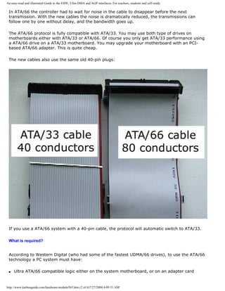
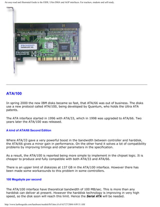
![An easy-read and illustrated Guide to the EIDE, Ultra DMA and AGP interfaces. For teachers, students and self-study.
Another technology we will see more and more is ATA-based RAID. Using two or four cheap
ATA-disks you can have a very powerfull disk system with doubled bandwidth. This requires a
RAID-controller like the Promise FastTrak or a motherboard with onboard controller.
Theserequires higher bandwiths in the ATA protocols to show real powerful performances.
ATA/133
In 2001 some hardware vendors introduced ATA/133 as new version of the interface.
Serial ATA
Another more interesting new technology is the Serial ATA. Intel, Dell, IBM, Maxtor, Quantum
and Seagate and other partners are about to replace ATA/100 with a faster drive interface.
The new Serial ATA interface, can pump out 160 MB per second in the first version (Serial ATA
1x or SA1X). Later version promises bandwiths up to 528 MB per second. This will give us
headroom for the next five years of harddisk technology improvements.
Even more promising is the new cable design of Serial ATA. Instead of 40/80 conducters the
cables only holds four conductors. This thinner cabling is great news for everyone putting
together his own PC. I also expect the number of onboard ATA-channels to increase from 4 to
8.
Serial ATA probably will kill the remaining hope for generel use of the IEEE 1394/FireWire
interface for PC's harddisks. This was never really supported by Intel.
Hopefully the new interface will operate with a command queue, which has been a great lack in
ATA-design compared to SCSI.
q Next page
q Previous page
To learn more
[top]
Read more the boot process and system bus in Module 2b
http://www.karbosguide.com/hardware/module5b5.htm (5 of 6)7/27/2004 4:09:31 AM](https://image.slidesharecdn.com/computerrepair-acompleteillustratedguidetopchardware-140318001250-phpapp01/85/Computer-repair-_a_complete_illustrated_guide_to_pc_hardware-551-320.jpg)
![An easy-read and illustrated Guide to the EIDE, Ultra DMA and AGP interfaces. For teachers, students and self-study.
Read about file systems in module 6a
Read about I/O buses in module 2c
Read about the motherboard chip set in module 2d
Read about RAM in module 2e
Read Module 5c about SCSI, USB etc.
Read module 7a about monitors, and 7b on graphics card.
[Main page] [Contact] [Karbo's Dictionary] [The Software Guides]
Copyright (c) 1996-2001 by Michael B. Karbo. www.karbosguide.com.
http://www.karbosguide.com/hardware/module5b5.htm (6 of 6)7/27/2004 4:09:31 AM](https://image.slidesharecdn.com/computerrepair-acompleteillustratedguidetopchardware-140318001250-phpapp01/85/Computer-repair-_a_complete_illustrated_guide_to_pc_hardware-552-320.jpg)
![An easy-read and illustrated Guide to the EIDE, Ultra DMA and AGP interfaces. For teachers, students and self-study.
Please click the banners to support our work!
KarbosGuide.com. Module 5b6.
Practical hints to setting up a harddisk
The contents:
q Setting up the disk
q The BIOS
q Next page
q Previous page
Configuring your EIDE hard disk [top]
Please support our
sponsor.
Often setting up a hard disk is very easy. But sometimes it teases you - sometimes even a lot. Let me here describe a few
checkpoints:
q The cabling. Your hard disk has to be connected to the master EIDE channel, and the connection has to be ensured.
q The jumpers - is the drive a slave or a master? Read below.
q The BIOS setup has to be configured. Read below.
q Run FDISK to partition the hard disk. Boot from a diskette with fdisk.exe on it. Read about file systems in module 6a.
Slave or master
If you connect EIDE harddisk number 2, you probably have to connect as a slave unit on the primary EIDE channel. This is not
very good, as I describe it in the article Please also read the article "Problems with assigning two EIDE harddisks".
Anyway, I'll use this setup as example. You have to make sure the jumper setting is correct. Here is the text from a Maxtor
manual, which tells how to set the unit up as a master or a slave. It is very easy - and it works:
http://www.karbosguide.com/hardware/module5b6.htm (1 of 4)7/27/2004 4:09:34 AM](https://image.slidesharecdn.com/computerrepair-acompleteillustratedguidetopchardware-140318001250-phpapp01/85/Computer-repair-_a_complete_illustrated_guide_to_pc_hardware-553-320.jpg)
![An easy-read and illustrated Guide to the EIDE, Ultra DMA and AGP interfaces. For teachers, students and self-study.
The jumpers are on the back side of the drive, between the cable and power connectors:
The BIOS
BIOS is a low-level layer of system software. The BIOS has to identify the hard disk at the Start-up. If BIOS does not have the
proper values for the specific hard disk, it will not function. There will be no access to the hard disk.
The hard disk is recognized by BIOS on certain parameters like number of cylinders, number of heads, sectors etc. These values
are to be stored in the CMOS memory. But often the PC cannot identify these values without a helping hand. I here describe the
installation as I know it (the ROM software is from Award). It is not complicated at all, but it involves two menus from the Setup
utility.
If you have mounted your hard disk and ensured that the cabling is correct, it is time to boot the PC. Then you hit the [Delete]-key
to enter the Setup program. First you choose "IDE HDD AUTO DETECTION" as here:
Then you have to let the program detect each of the four EIDE channels. On the first one you should find your hard disk. If not -
then something definitely is wrong.
http://www.karbosguide.com/hardware/module5b6.htm (2 of 4)7/27/2004 4:09:34 AM](https://image.slidesharecdn.com/computerrepair-acompleteillustratedguidetopchardware-140318001250-phpapp01/85/Computer-repair-_a_complete_illustrated_guide_to_pc_hardware-554-320.jpg)
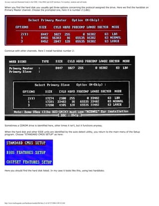
![An easy-read and illustrated Guide to the EIDE, Ultra DMA and AGP interfaces. For teachers, students and self-study.
Be aware that the list above has to correspond directly to the physically installed units - especially if you reconfigure your system.
Otherwise it won't work. This has teased me when I installed hard disk number two and changed the master/slave setup. It is not
enough to run the auto detect, also the standard CMOS setup menu has to be updated.
When all this is in place, you have to save the changes and reboot.
q Next page
q Previous page
To learn more
[top]
Read more the boot process and system bus in Module 2b
Read about file systems in module 6a
Read about I/O buses in module 2c
Read about the motherboard chip set in module 2d
Read about RAM in module 2e
Read Module 5c about SCSI, USB etc.
Read module 7a about monitors, and 7b on graphics card.
[Main page] [Contact] [Karbo's Dictionary] [The Software Guides]
Copyright (c) 1996-2001 by Michael B. Karbo. www.karbosguide.com.
http://www.karbosguide.com/hardware/module5b6.htm (4 of 4)7/27/2004 4:09:34 AM](https://image.slidesharecdn.com/computerrepair-acompleteillustratedguidetopchardware-140318001250-phpapp01/85/Computer-repair-_a_complete_illustrated_guide_to_pc_hardware-556-320.jpg)
![An easy-read and illustrated Guide to the AGP interface. For teachers, students and self-study.
Please click the banners to support our work!
KarbosGuide.com. Module 5b7.
About the interface AGP
The contents:
q Introducing AGP?
q The technology
q Next page
q Previous page
What is AGP?
A new bus was introduced in 1997. It is called AGP (Accelerated
Graphics Port), and it is exclusively designed for video cards.
Introduction
AGP was designed with two purposes:
[top]
Please support our
sponsor.
q To relieve the PCI bus of work with graphics data. Hence, it can concentrate on other demanding
transport duties, like transfer to and from network adapter and disk drives.
q To have better bandwidth within the video system.
http://www.karbosguide.com/hardware/module5b7.htm (1 of 5)7/27/2004 4:09:36 AM](https://image.slidesharecdn.com/computerrepair-acompleteillustratedguidetopchardware-140318001250-phpapp01/85/Computer-repair-_a_complete_illustrated_guide_to_pc_hardware-557-320.jpg)
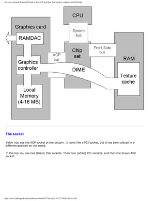
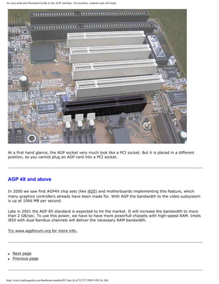
![An easy-read and illustrated Guide to the AGP interface. For teachers, students and self-study.
To learn more
[top]
Read more the boot process and system bus in Module 2b
Read about file systems in module 6a
Read about I/O buses in module 2c
Read about the motherboard chip set in module 2d
Read about RAM in module 2e
Read Module 5c2 about USB.
Read module 7a about monitors, and 7b on graphics card.
[Main page] [Contact] [Karbo's Dictionary] [The Software Guides]
Copyright (c) 1996-2001 by Michael B. Karbo. www.karbosguide.com.
http://www.karbosguide.com/hardware/module5b7.htm (5 of 5)7/27/2004 4:09:36 AM](https://image.slidesharecdn.com/computerrepair-acompleteillustratedguidetopchardware-140318001250-phpapp01/85/Computer-repair-_a_complete_illustrated_guide_to_pc_hardware-561-320.jpg)
![An easy-read and illustrated Guide to SCSI, IEE1394 FireWire and USB.
Please click the banners to support our work!
KarbosGuide.com. Module 5c1a.
About SCSI
The contents:
q The host adapter
q 7 units in a chain On the following page:
q SCSI is intelligent
q About the SCSI standards
q What do you gain with SCSI?
q Next module: USB
q IEEE1394 FireWire
q Device Bay
q Next page
q Previous page
Introduction [top]
Please support our
sponsor.
SCSI (Small Computer System Interface) is high end technology. It is a technology which provide
means for data exchange among hardware devices such as drives, tape streamers and scanners. SCSI is
especially used in high end PCs such as network servers or just powerful workstations.
SCSI might be compared to the EIDE interface, which also uses a host adapter controlling drives.
However SCSI has two major advantages over EIDE:
q A SCSI host controls 7 or 15 devices (using only one IRQ).
q The SCSI system holds its own computer power, thus freeing the CPU from workload.
If you are critical about your PC power, the SCSI would be worth considering.
http://www.karbosguide.com/hardware/module5c1a.htm (1 of 5)7/27/2004 4:09:38 AM](https://image.slidesharecdn.com/computerrepair-acompleteillustratedguidetopchardware-140318001250-phpapp01/85/Computer-repair-_a_complete_illustrated_guide_to_pc_hardware-562-320.jpg)
![An easy-read and illustrated Guide to SCSI, IEE1394 FireWire and USB.
The host adapter
[top]
A SCSI system is built around a central, intelligent controller called the host adapter . A host adapter
can control several SCSI units:
q Many units on the same host adapter.
q Many types of drives : Hard disks, CD and DVD drives, Zip drives, MO drives, etc.
q Tape streamers (DAT and others).
q Scanners.
The host adapter has its own BIOS separate from the PC's. When you boot the PC, you will see the
adapter communicating with connected SCSI devices.
The adapter is rather expensive. Currently, the best for ordinary use is called Adaptec 2940 U2W (priced
at around $200). It is PCI based, so you could use it in your next PC too. I have had good experiences
with ASUS motherboards in versions with onboard SCSI controller. That is the most easy solution - to
have the controller onboard.
7 units in a chain
[top]
The regular SCSI 2 system can handle 8 devices including the adapter itself. SCSI Wide handles 15
devices. Each device has to be assigned a unique number going from ID 0 to ID 7. The SCSI devices can
be internal (installed inside the PC cabinet) or external . The host adapter is a device itself. Typically,
the host adapter will occupy ID 7.
Here is an illustration of a SCSI string with host adapter (ID 7) and five units (ID numbers 0, 1, 2, 4,
and 5):
http://www.karbosguide.com/hardware/module5c1a.htm (2 of 5)7/27/2004 4:09:38 AM](https://image.slidesharecdn.com/computerrepair-acompleteillustratedguidetopchardware-140318001250-phpapp01/85/Computer-repair-_a_complete_illustrated_guide_to_pc_hardware-563-320.jpg)
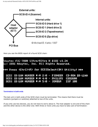
![An easy-read and illustrated Guide to SCSI, IEE1394 FireWire and USB.
q Next page
q Previous page
Learn more [top]
Read about FireWire in module 5c3
Read about chip sets on the motherboard in module 2d
Read Module 4d about super diskette and MO drives.
Read module 5a about expansion cards, where we evaluate the I/O buses from the port side.
Read module 5b about AGP
Read module 7a about monitors, and 7b on graphics card.
Read module 7c about sound cards, and 7d on digital sound and music.
http://www.karbosguide.com/hardware/module5c1a.htm (4 of 5)7/27/2004 4:09:38 AM](https://image.slidesharecdn.com/computerrepair-acompleteillustratedguidetopchardware-140318001250-phpapp01/85/Computer-repair-_a_complete_illustrated_guide_to_pc_hardware-565-320.jpg)
![An easy-read and illustrated Guide to SCSI, IEE1394 FireWire and USB.
[Main page] [Contact] [Karbo's Dictionary] [The Software Guides]
Copyright (c) 1996-2001 by Michael B. Karbo. www.karbosguide.com.
http://www.karbosguide.com/hardware/module5c1a.htm (5 of 5)7/27/2004 4:09:38 AM](https://image.slidesharecdn.com/computerrepair-acompleteillustratedguidetopchardware-140318001250-phpapp01/85/Computer-repair-_a_complete_illustrated_guide_to_pc_hardware-566-320.jpg)
![An easy-read and illustrated Guide to SCSI, IEE1394 FireWire and USB.
Please click the banners to support our work!
KarbosGuide.com. Module 5c1b.
About SCSI - continued
The contents:
q SCSI is intelligent
q About the SCSI standards
q What do you gain with SCSI?
q Next page
q Previous page
SCSI is intelligent [top]
Please support our
sponsor.
SCSI is remarkable in having an intelligent protocol, which assures maximum utilization of the data transfer. The
basis of SCSI is a set of commands . Each individual device holds its own controller, which interprets these
commands.
All commands within the SCSI system are handled internally, meaning the CPU does not have to control the
process:
http://www.karbosguide.com/hardware/module5c1b.htm (1 of 5)7/27/2004 4:09:40 AM](https://image.slidesharecdn.com/computerrepair-acompleteillustratedguidetopchardware-140318001250-phpapp01/85/Computer-repair-_a_complete_illustrated_guide_to_pc_hardware-567-320.jpg)
![An easy-read and illustrated Guide to SCSI, IEE1394 FireWire and USB.
While the read/write head moves across a SCSI disk, the host adapter as well as the CPU can handle other jobs.
Therefore SCSI is well suited for multitasking environments.
About the SCSI standard
[top]
SCSI stands for Small Computer System Interface. It is intended as a universal interface, defined and designed
in 1982 by NCR and Shugart Associates. It exists in numerous variations. Here you see some of the more
significant editions:
Standard Year Bus speed Bus width Max. bandwidth
Standard SCSI 1986 5 MHz
(Asynchronous)
8 bit 5 MB/sec
Fast SCSI
Narrow
1990 10 MHz
(Synchronous)
8 bit 10 MB/sec
Fast SCSI
Wide
1992 10 MHz
(Synchronous)
16 bit 20 MB/sec
Ultra SCSI 1994 20 MHz
(Synchronous)
16 bit 40 MB/sec
LVD Ultra2 1996 40 MHz 16 bit 80 MB/sec
Today there are many SCSI standards. Among others, you can come across SCSI-20 and SCSI-40, which refers
to the bus speed. The SCSI standard seem to have its own life with plenty of new development.
LVD Ultra2
The latest version of SCSI is called LVD ( Low Voltage Differentiale). You also find the term SCSI Ultra 2 - there
have always been so many terms... LVD is an improvement to SCSI-3.
LVD gives twice the bandwidth of the ordinary SCSI-3. Another improvement is the cabling which works up to 12
http://www.karbosguide.com/hardware/module5c1b.htm (2 of 5)7/27/2004 4:09:40 AM](https://image.slidesharecdn.com/computerrepair-acompleteillustratedguidetopchardware-140318001250-phpapp01/85/Computer-repair-_a_complete_illustrated_guide_to_pc_hardware-568-320.jpg)
![An easy-read and illustrated Guide to SCSI, IEE1394 FireWire and USB.
meters. Traditional SCSI only works within 3 meters. LVD has to compete with FireWire, which also has a
powerful bandwidth.
Adaptec have a SCSI-controller delivering up to 160 MB/sec. This unitcalled Adaptec SCSI Card 3950U2 uses two
independent Ultra2 SCSI buses in one card. It connects up to 30 SCSI devices!
What do you gain with SCSI?
[top]
Expensive but good. SCSI makes the PC a more expensive, but more versatile. The advantages are, that on the
same PC you have free access to use many and good units:
q It is easy to add accessories as DAT streamers, CD-ROM recorders, MO drives, scanners, ZIP- and DVD-drives
etc.
q You can use SCSI hard disks.
q You can use CDROM drives on SCSI, which may give a better performance.
The advantages of SCSI hard disks
SCSI hard disk are generally of higher quality than other disks.Typically, good SCSI disks come with a 5 year
warranty. Traditionally they are faster than the EIDE disks. At 10,000 or 14,000 RPM they have shorter seek
times. They also have a bigger cache.
Another advantage is the large number of accessories, which can be attached. If you buy a 18 GB SCSI disk
today, you will guaranteed need additional disk storage in a few years. Then you just add disk number two to the
SCSI chain, and later number three. The system is more flexible than EIDE, where you can have a maximum of
four units incl. CD-ROM.
The SCSI hard disks can also adjust the sequence in the PC's disk read commands. This allows reading the tracks
in an optimal sequence, enabling minimal movements of the read/write head. Quantum calls this technology
ORCA ( Optimized Reordering Command Algorithm ). It should improve performance by 20%.
Finally, the SCSI controller can multitask, so the CPU is not locked up during hard disk operations, which you can
experience with IDE.
SCSI hard disks can achieve substantially larger transfer capacity than the IDE drives, but they have the same
bottle necks: the serial handling of bits in the read/write head, where the capacity is highly dependent on the
rotation speed.
SCSI is for servers
However, today the importance of SCSI is decreasing except for use in dedicated servers. Modern CD-ROM and
CD-RW drives work just as good on EIDE as on SCSI. USB has taken over when it comes to controlling units like
scanners, cameras and Zip drives.
Finally, modern EIDE-based harddisks have an extremely high quality compared to the products we had five
years ago. Hence, there is no reason to prefer SCSI-based harddisk to the more inexpensive EIDE drives.
http://www.karbosguide.com/hardware/module5c1b.htm (3 of 5)7/27/2004 4:09:40 AM](https://image.slidesharecdn.com/computerrepair-acompleteillustratedguidetopchardware-140318001250-phpapp01/85/Computer-repair-_a_complete_illustrated_guide_to_pc_hardware-569-320.jpg)
![An easy-read and illustrated Guide to SCSI, IEE1394 FireWire and USB.
But for servers SCSI still has a market.
Booting from SCSI disk
If the hard disk has to be booted, traditionally it has to be assigned ID 0. If the SCSI controller has to control the
hard disk, then the PC CMOS setup must be modified, so the (IDE) hard disk is not installed if not both types of
hard disks are installed.
The operating system will find the host adapter after start up and BIOS will be read from the hard disk through
the adapter. New BIOSs allow a choice of booting from either IDE or SCSI disk.
Fast and Ultra Wide
The newest generation of SCSI hard disks are both fast, ultra and wide. Therefore, the best advice is to buy an
adapter like Adaptec 2940UW2, which can handle the newest disks.
IBM disks
Allow me to advertise IBM's SCSI disks. They are fantastically good. Unfortunately, not many people know about
them. I have had a few of them. They excel in high quality at reasonable prices. The physical construction is very
appealing: The electronics are integrated in very few components. Everything exudes quality! And they are very
quiet. You simply cannot hear them.
32 bit problems in Windows 3.11
Windows 32 Bit Disk Access has given problems with SCSI disks. For a long while, it was impossible to install a
32 bit driver in Windows 3.11 to the SCSI disk. This was solved in 1995 and there have been no problems with
Windows and SCSI since then.
Links
About SCSI: SCSI Pro and DPT offer some information.
q Next page
q Previous page
Learn more [top]
Read about FireWire in module 5c3
Read about chip sets on the motherboard in module 2d
Read Module 4d about super diskette and MO drives.
Read module 5a about expansion cards, where we evaluate the I/O buses from the port side.
http://www.karbosguide.com/hardware/module5c1b.htm (4 of 5)7/27/2004 4:09:40 AM](https://image.slidesharecdn.com/computerrepair-acompleteillustratedguidetopchardware-140318001250-phpapp01/85/Computer-repair-_a_complete_illustrated_guide_to_pc_hardware-570-320.jpg)
![An easy-read and illustrated Guide to SCSI, IEE1394 FireWire and USB.
Read module 5b about AGP
Read module 7a about monitors, and 7b on graphics card.
Read module 7c about sound cards, and 7d on digital sound and music.
[Main page] [Contact] [Karbo's Dictionary] [The Software Guides]
Copyright (c) 1996-2001 by Michael B. Karbo. www.karbosguide.com.
http://www.karbosguide.com/hardware/module5c1b.htm (5 of 5)7/27/2004 4:09:40 AM](https://image.slidesharecdn.com/computerrepair-acompleteillustratedguidetopchardware-140318001250-phpapp01/85/Computer-repair-_a_complete_illustrated_guide_to_pc_hardware-571-320.jpg)

![Tips for Windows.
Karbosguide.com. Software Tip 1
What are the advantages of Windows 98?
q Next page
q Previous
page
In my opinion and experience Windows 98 was an
excellent operating system when introduced. At its
introduction in the spring of 1998, some papers
made the comment "it is not worth the money"
and "there is not much new compared to Windows
95." I did not agree with them.
Please support our
sponsor.
Here are some of the advantages compared to earlier versions of Windows:
Generally better performance
Generally Windows 98 utilizes the PC resources better:
q Memory management has been completely changed. It finally works.
q The file system is better integrated into the operating system, which gives new
functionality.
q Program loading can be up to four times as fast.
q Hardware support is significantly improved with a new driver model, and all new chipsets
etc. are supported. However these conditions may change.
These improvements are sufficiently significant to justify an upgrade.
Better user interface
[top]
Superficially the Windows 95 user interface has not changed much. But you need not dig
down very deep to see many novelties. I am talking about small items with better
adaptations in the Start menu, new tool bars, etc. But these small items are really very smart
when you need to set the user interface.
Better system tools
The system tools are significant for the more demanding user, who really wants to know and
http://www.karbosguide.com/software/01.htm (1 of 2)7/27/2004 4:09:42 AM](https://image.slidesharecdn.com/computerrepair-acompleteillustratedguidetopchardware-140318001250-phpapp01/85/Computer-repair-_a_complete_illustrated_guide_to_pc_hardware-574-320.jpg)
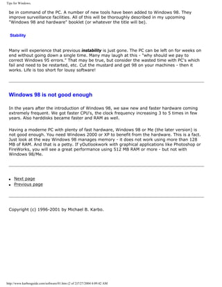
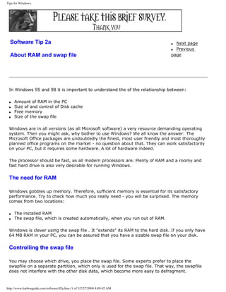
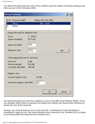
![An illustrated Guide to the latest chip sets for Intel's P6 processors
Intro to Intel 810
[top]
With i810, Intel has launched the first chip set of a new generation.
In late April 1999 the 810 "Whitney" chip set was introduced. This set is new in several
aspects.
q A new type of memory controller with built-in graphics technology.
q Support for up to 512 MB SDRAM.
q Built-in audio-codec controller.
q No ISA bus!
810 is an inexpensive chip set built on the BX technology. However, the new memory bus will
come in other chip sets as well. The built-in audio-codec controller enables software audio and
modem implementations. This meens that no sound card or modem is required. And finally we
see the first attempt to produce modern PC's without the old ISA bus.
Chips in 810
The chip set consists of three chips:
82810 Graphics Memory Controller Hub 421 Ball Grid Array (BGA)
82801 Integrated Controller Hub 241 Ball Grid Array (BGA)
http://www.karbosguide.com/hardware/module2d06.htm (2 of 7)7/27/2004 4:09:46 AM](https://image.slidesharecdn.com/computerrepair-acompleteillustratedguidetopchardware-140318001250-phpapp01/85/Computer-repair-_a_complete_illustrated_guide_to_pc_hardware-582-320.jpg)
![An illustrated Guide to the latest chip sets for Intel's P6 processors
82802 Firmware Hub 32-pin PLCC or 40-pin TSOP
The Accelerated Hub Architecture [top]
Usually we talk about north and south bridges in chip sets. These refer
to the two controllers a chip set usually consists of. Intel replaces these
terms with "hubs".
The new thing in this hub architecture is, that the two controllers not
are connected by the PCI bus. Instead they connect via a new Interlink
dedicated bus. This is a high speed bus, currently with twice the
bandwidth of the PCI bus. This architecture resembles the new K7
Athlon point to point channel.
Please support our
sponsor.
266 MB/sec
The interlink bus operates at 133 MHz in 2X mode. Being 64 bit wide this gives a bandwidth of
266 MB/sec (2 X 133.000.000 X 8 byte).
http://www.karbosguide.com/hardware/module2d06.htm (3 of 7)7/27/2004 4:09:46 AM](https://image.slidesharecdn.com/computerrepair-acompleteillustratedguidetopchardware-140318001250-phpapp01/85/Computer-repair-_a_complete_illustrated_guide_to_pc_hardware-583-320.jpg)
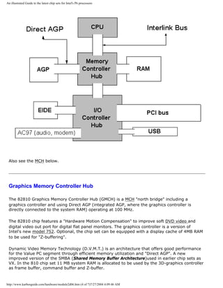
![An illustrated Guide to the latest chip sets for Intel's P6 processors
82801 I/O Controller Hub
This "south bridge", the 82801 (ICH), employs an accelerated hub to give a direct connection
from the graphics and memory to the integrated AC97 (Audio-Codec) controller, the IDE
controllers, the dual USB ports, and the PCI bus. This promises increased I/O performance.
82802 Firmware Hub (FWH)
The 82802 Firmware Hub (FWH) stores system BIOS and video BIOS in a 4 Mbit EEPROM. In
addition, the 82802 contains a hardware Random Number Generator (RNG), which (perhaps
and in time) will enable better security, stronger encryption, and digital signing in the Internet.
AC97
The Integrated Audio-Codec 97 controller enables software audio and modem by using the
processor to run sound and modem software. It will require software, but using this you need
no modem or soundcard.
This feature is smart if you do not use audio or modem on a regular basis. It adds a heavy
work to the CPU, which has to act as a modem and as a sound card beside its regular tasks.
Karbo's conclusion
[top]
The 82810 controller represent a new generation of low-priced chip sets. I find these aspects
interesting:
Integration of a powerful graphics accelerator
The RAMDAC is of 230 MHz giving a max. 2D-resolution of 1280 X 1024 pixels with 24 bit color
depth and a refresh rate of 85 Hz. The graphics controller offers 3D acceleration with both
DirextX and OpenGL support.
I found the performance to be quite OK for non-game use. The visual quality of the screen
images seemed to match the out put from mid-range graphics adapters from ATI and Matrox. I
could live with this graphics without any problems.
Here you see a dump from the Windows -driver that goes with the chip set:
http://www.karbosguide.com/hardware/module2d06.htm (5 of 7)7/27/2004 4:09:46 AM](https://image.slidesharecdn.com/computerrepair-acompleteillustratedguidetopchardware-140318001250-phpapp01/85/Computer-repair-_a_complete_illustrated_guide_to_pc_hardware-585-320.jpg)

![An illustrated Guide to the latest chip sets for Intel's P6 processors
The 810 chip set is made for Intel Celeron processors. But so far these processors only work
with a system bus frequency of 66 MHz. Why does the chip set then support 100 MHz? The
obvious reason is that Intel planed to move the Pentium III processors to a Socket 370
platform. And the Celerons comes operating at a 100 MHz bus frequency. This is good news,
and it all happened in 2000 and 2001.
Go for i815E
After the arrival of i815E in June 2000, that is the chip set to go for. It holds all the nice
features from i810 plus a lot of great news.
q Next page
q Previous page
Learn more [top]
Read about the Pentium in module 3c
Read about the Pentium II's etc. in module 3e
[Main page] [Contact] [Karbo's Dictionary] [The Software Guides]
Copyright (c) 1996-2001 by Michael B. Karbo. KarbosGuide.com
http://www.karbosguide.com/hardware/module2d06.htm (7 of 7)7/27/2004 4:09:46 AM](https://image.slidesharecdn.com/computerrepair-acompleteillustratedguidetopchardware-140318001250-phpapp01/85/Computer-repair-_a_complete_illustrated_guide_to_pc_hardware-587-320.jpg)
![An illustrated Guide to the i820 chip set
Intro to Intel 820
[top]
In 1999 the new generation of high-end Intel chip set was code named "Camino".
This i820 "Camino" chip sets was originally set for debut in May or June, but were delayed.
The Rambus technology was problematic.
The i820 chip set was finally to be launched September 27th, 1999 but was delayed again.
This time motherboards with more than two SDRAM sockets did not work. And there have
been so many problems with this chip set, which soon became a nightmare for Intel. In the
press the situation was described as "Caminogate"
Anyway, we have to look into the architecture. We find:
q New hub-based architecture
q 133 MHz FSB
q Rambus
q Up to 1GB RAM
q AGP4X
q ATA66
The chipset was designed for high-end use with Pentium III processors.
Please support our
sponsor.
The chips in i820
The chip set consists of two main controllers:
q The 82820 Memory Controller Hub.
q The 82801 I/O Controller Hub (ICH)
The (MCH) provides the CPU interface, DRAM interface, and AGP interface. This chip is found
in two versions: A single processor (82820) or a dual processorchip (82820DP).
http://www.karbosguide.com/hardware/module2d07.htm (2 of 3)7/27/2004 4:09:48 AM](https://image.slidesharecdn.com/computerrepair-acompleteillustratedguidetopchardware-140318001250-phpapp01/85/Computer-repair-_a_complete_illustrated_guide_to_pc_hardware-589-320.jpg)
![An illustrated Guide to the i820 chip set
The ICHmakes a direct connection from the graphics and memory to the integrated AC97
controller, the ATA66 controller, dual USB ports, and PCI add-in cards.
Besides the two main controllers you also find:
q 82380AB PCI-ISA Bridge
q 82802 Firmware Hub
q Next page
q Previous page
Learn more [top]
Read about the Pentium in module 3c
Read about the Pentium II's etc. in module 3e
[Main page] [Contact] [Karbo's Dictionary] [The Software Guides]
Copyright (c) 1996-2001 by Michael B. Karbo. KarbosGuide.com
http://www.karbosguide.com/hardware/module2d07.htm (3 of 3)7/27/2004 4:09:48 AM](https://image.slidesharecdn.com/computerrepair-acompleteillustratedguidetopchardware-140318001250-phpapp01/85/Computer-repair-_a_complete_illustrated_guide_to_pc_hardware-590-320.jpg)
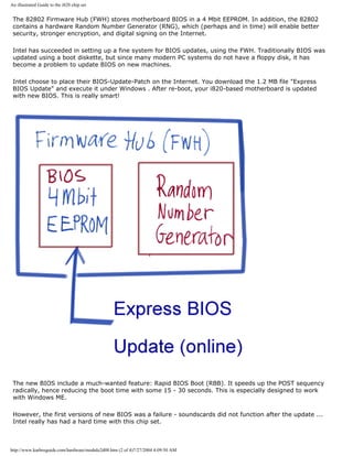
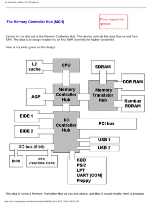
![An illustrated Guide to the i820 chip set
boards using PC133 RAM as well as RDRAM. A sound idea, indeed. DDR was never planned, since Intel
is not allowed using this type of RAM, according to their agreement with Rambus (covering the years
2000-2002).
q Next page
q Previous page
Learn more [top]
Read about the Pentium in module 3c
Read about the Pentium II's etc. in module 3e
[Main page] [Contact] [Karbo's Dictionary] [The Software Guides]
Copyright (c) 1996-2001 by Michael B. Karbo. KarbosGuide.com
http://www.karbosguide.com/hardware/module2d08.htm (4 of 4)7/27/2004 4:09:50 AM](https://image.slidesharecdn.com/computerrepair-acompleteillustratedguidetopchardware-140318001250-phpapp01/85/Computer-repair-_a_complete_illustrated_guide_to_pc_hardware-594-320.jpg)
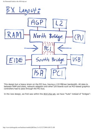
![An illustrated Guide to the i820 chip set
q Next page
q Previous page
Learn more [top]
Read about the Pentium in module 3c
Read about the Pentium II's etc. in module 3e
http://www.karbosguide.com/hardware/module2d09.htm (4 of 5)7/27/2004 4:09:52 AM](https://image.slidesharecdn.com/computerrepair-acompleteillustratedguidetopchardware-140318001250-phpapp01/85/Computer-repair-_a_complete_illustrated_guide_to_pc_hardware-598-320.jpg)
![An illustrated Guide to the i820 chip set
[Main page] [Contact] [Karbo's Dictionary] [The Software Guides]
Copyright (c) 1996-2001 by Michael B. Karbo. KarbosGuide.com
http://www.karbosguide.com/hardware/module2d09.htm (5 of 5)7/27/2004 4:09:52 AM](https://image.slidesharecdn.com/computerrepair-acompleteillustratedguidetopchardware-140318001250-phpapp01/85/Computer-repair-_a_complete_illustrated_guide_to_pc_hardware-599-320.jpg)
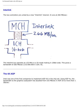
![An illustrated Guide to the i820 chip set
However the price of RDRAM was extremely high in the first year of i820. Therefore, i820
never became popular.
q Next page
q Previous page
Learn more [top]
Read about the Pentium in module 3c
Read about the Pentium II's etc. in module 3e
[Main page] [Contact] [Karbo's Dictionary] [The Software Guides]
Copyright (c) 1996-2001 by Michael B. Karbo. KarbosGuide.com
http://www.karbosguide.com/hardware/module2d10.htm (4 of 4)7/27/2004 4:09:54 AM](https://image.slidesharecdn.com/computerrepair-acompleteillustratedguidetopchardware-140318001250-phpapp01/85/Computer-repair-_a_complete_illustrated_guide_to_pc_hardware-603-320.jpg)
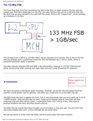
![An illustrated Guide to the i820 chip set
First of all the company should not commit themselves to an uncertain technology like RAMBUS as
they did. Intel produces great CPUs. The customers might use them with Rambus or SDRAM or
DDRRAM or EXP3RAM or whatever the industry might come up with.
We believe that Intel trusted to much in own powers; they wanted to "force" the market into a
certain behavior. We do not like that; it is against the free will and intelligence of users all over the
world. Last time Intel tried this attitude was in 1997 when skipping Socket 7 in favour of Slot 1. A
clupmsy design, which they now have abandoned themselves.
The second lesson is that Intel never again should market untested products. We have seen this
several times during the "Caminogate" affair. Maybe Intel has felt threathend by AMD's succesfull
Athlon project. But there is no excuse for marketing lousy untested products. Both Intel and
Microsoft should learn from this.
q Next page
q Previous page
Learn more [top]
Read about the Pentium in module 3c
Read about the Pentium II's etc. in module 3e
[Main page] [Contact] [Karbo's Dictionary] [The Software Guides]
Copyright (c) 1996-2001 by Michael B. Karbo. KarbosGuide.com
http://www.karbosguide.com/hardware/module2d11.htm (3 of 3)7/27/2004 4:09:56 AM](https://image.slidesharecdn.com/computerrepair-acompleteillustratedguidetopchardware-140318001250-phpapp01/85/Computer-repair-_a_complete_illustrated_guide_to_pc_hardware-606-320.jpg)
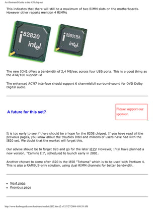
![An illustrated Guide to the i820 chip set
Learn more [top]
Read about the Pentium in module 3c
Read about the Pentium II's etc. in module 3e
[Main page] [Contact] [Karbo's Dictionary] [The Software Guides]
Copyright (c) 1996-2001 by Michael B. Karbo. KarbosGuide.com
http://www.karbosguide.com/hardware/module2d12.htm (3 of 3)7/27/2004 4:09:58 AM](https://image.slidesharecdn.com/computerrepair-acompleteillustratedguidetopchardware-140318001250-phpapp01/85/Computer-repair-_a_complete_illustrated_guide_to_pc_hardware-609-320.jpg)
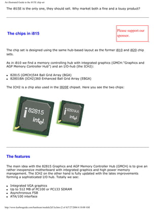
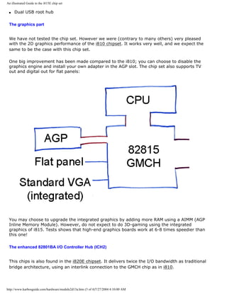
![An illustrated Guide to the i815E chip set
The two USB controllers double the bandwidth to 2.4 MBps across four USB ports.
AC97 audio supports full surround sound with up to 6 channels and a soft modem
implementation.
The integrated LAN is used for three networking environments (1Mbps, 10/100Mbps LAN and
managed 10/100Mbps LAN). This means that we do not need an ethernet adapter, it is all in
the chipset!s
ATA/100 is a great new interface giving a noticeable improvement to disk performance if the
disk is build to ATA/100. Otherwise the interface is fully downwards compatible.
q Next page
q Previous page
Learn more [top]
Read about the Pentium in module 3c
Read about the Pentium II's etc. in module 3e
[Main page] [Contact] [Karbo's Dictionary] [The Software Guides]
Copyright (c) 1996-2001 by Michael B. Karbo. KarbosGuide.com
http://www.karbosguide.com/hardware/module2d13a.htm (4 of 4)7/27/2004 4:10:00 AM](https://image.slidesharecdn.com/computerrepair-acompleteillustratedguidetopchardware-140318001250-phpapp01/85/Computer-repair-_a_complete_illustrated_guide_to_pc_hardware-613-320.jpg)
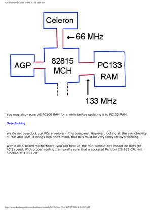
![An illustrated Guide to the i815E chip set
The "Almador" set
Please support our
sponsor.
The successor to i815 is codenamed "Almador" (maybe i817?). The intersting issue is that
Intel has announced support for SDRAM.
Using DDR RAM, Intel will have a very powerfull platform for Pentium III. Also the integrated
3D graphics engine will benefit from the better RAM bandwidth.
The south bridge of this set will be the new ICH3 chip with these features:
q ATA/100
q Six USB ports of version 2.0
q Integrated LAN etc. like the ICH2 of i815.
q Next page
q Previous page
Learn more [top]
Read about the Pentium in module 3c
Read about the Pentium II's etc. in module 3e
[Main page] [Contact] [Karbo's Dictionary] [The Software Guides]
Copyright (c) 1996-2001 by Michael B. Karbo. KarbosGuide.com
http://www.karbosguide.com/hardware/module2d13b.htm (4 of 4)7/27/2004 4:10:02 AM](https://image.slidesharecdn.com/computerrepair-acompleteillustratedguidetopchardware-140318001250-phpapp01/85/Computer-repair-_a_complete_illustrated_guide_to_pc_hardware-617-320.jpg)
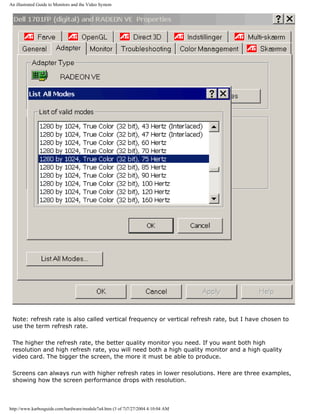
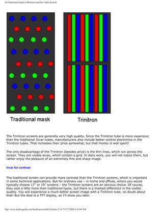
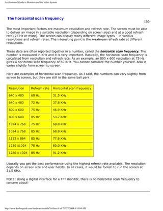
![An illustrated Guide to Monitors and the Video System
q Next page
q Previous page
To learn more Top
Read about video cards in Module 7b .
Read about sound cards in Module 7c .
Read about digital sound and music in Module 7d .
[Main page] [Contact] [Karbo's Dictionary] [The Software Guides]
http://www.karbosguide.com/hardware/module7a4.htm (7 of 7)7/27/2004 4:10:04 AM](https://image.slidesharecdn.com/computerrepair-acompleteillustratedguidetopchardware-140318001250-phpapp01/85/Computer-repair-_a_complete_illustrated_guide_to_pc_hardware-624-320.jpg)
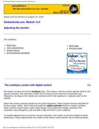
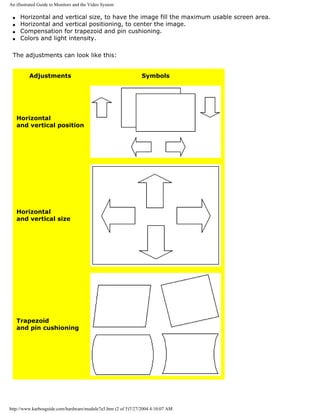
![An illustrated Guide to Monitors and the Video System
Ownership but here it refers to the Swedish Confederation of Professional Employees
(Tjänstmännens Central Organisation). They defined strong standards for emissions.
Finally, we have TCO-95, which is the strictest standard. Similar to TCO-92, it also includes
regulations on ergonomics (including refresh rates), maximum energy consumption,
environmentally friendly production and recycling facilities. The best screens comply with this
standard. Screens adhering to the TCO standards are more expensive. Obviously since they
are better screens.
The flat TFT screens do not emit any radiation at all and they consume considerably less
energy than the radiating screens. This is another indication that TFT may be the standard
screen of the future.
The VESA DPMS system is an energy saving technology, which includes both screen and
video card. A modern 17” screen consumes about 100 watt in normal use. With DPMS the
screen switches to two energy saving modes. First, power consumption drops to 25 watts and
finally again drops to 8 watt.
q Next page
q Previous page
To learn more
Top
Read about sound cards in Module 7c.
Read about digital sound and music in Module 7d .
[Main page] [Contact] [Karbo's Dictionary] [The Software Guides]
Copyright (c) 1996-2001 by Michael B. Karbo. www.karbosguide.com.
http://www.karbosguide.com/hardware/module7a5.htm (5 of 5)7/27/2004 4:10:07 AM](https://image.slidesharecdn.com/computerrepair-acompleteillustratedguidetopchardware-140318001250-phpapp01/85/Computer-repair-_a_complete_illustrated_guide_to_pc_hardware-629-320.jpg)
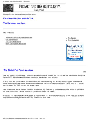
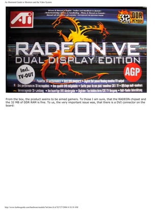
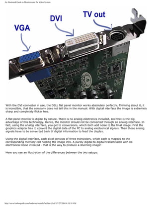
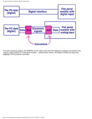
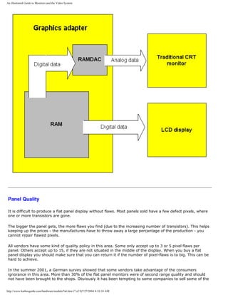
![An illustrated Guide to Monitors and the Video System
[Main page] [Contact] [Karbo's Dictionary] [The Software Guides]
Copyright (c) 1996-2001 by Michael B. Karbo. www.karbosguide.com.
http://www.karbosguide.com/hardware/module7a6.htm (9 of 9)7/27/2004 4:10:10 AM](https://image.slidesharecdn.com/computerrepair-acompleteillustratedguidetopchardware-140318001250-phpapp01/85/Computer-repair-_a_complete_illustrated_guide_to_pc_hardware-638-320.jpg)

This document provides an overview of digital data representation in computers. It explains that computers can only process data that is represented digitally using binary digits (bits) of 1s and 0s. Bytes made up of 8 bits can represent different characters using codes like ASCII. Common file types indicate whether the file contains program code, text, images or other user data. The document guides the reader through these concepts over multiple pages with examples and explanations of binary numbers, bytes, ASCII codes and file formats.