Downloaded 116 times
![1. ADD[6] Direct Pointer (The address of operand is available in instruction (ORIGINAL WORKING)) At location 6 (0110) , we are having address 9 (1001) of operand (1001011101).2. Add 6 Immediate (Data is part of instruction , data is not in any register or memory) Here, data is available is Instruction, 6 (0110) is itself is dataIADD[6] Indirect (Pointer) At location 6 (0110) , we are having address 9 (1001), of memory location which is having address of operand (1001011101).It means it is concept of pointer to pointer0110100110011001011101011010011001110011001001011101Krishna Kumar Bohra (KKB), MCA LMCSTwww.selectall.wordpress.com](https://image.slidesharecdn.com/coa-1four-090729080935-phpapp02/75/Computer-Organisation-Part-4-14-2048.jpg)
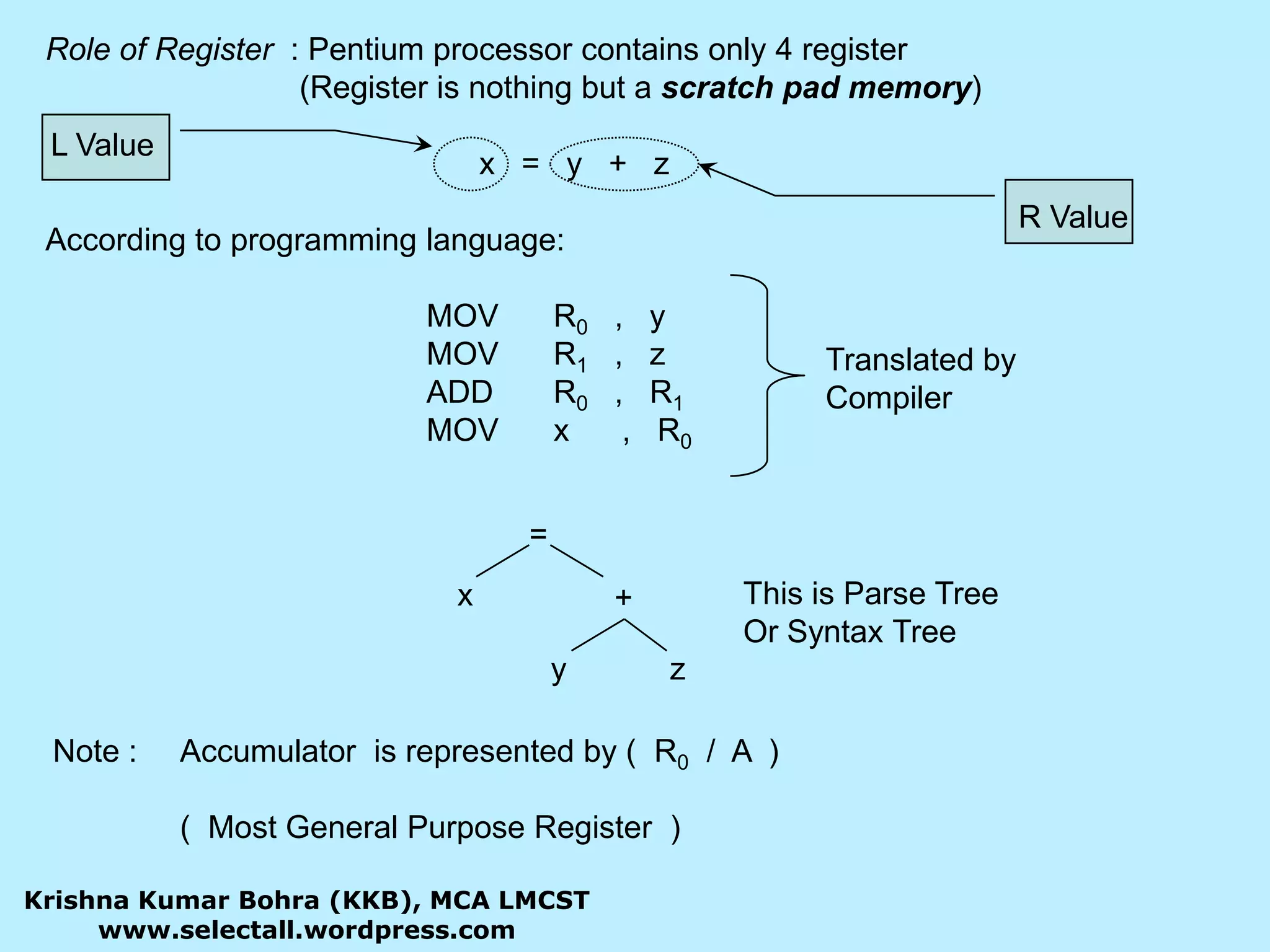
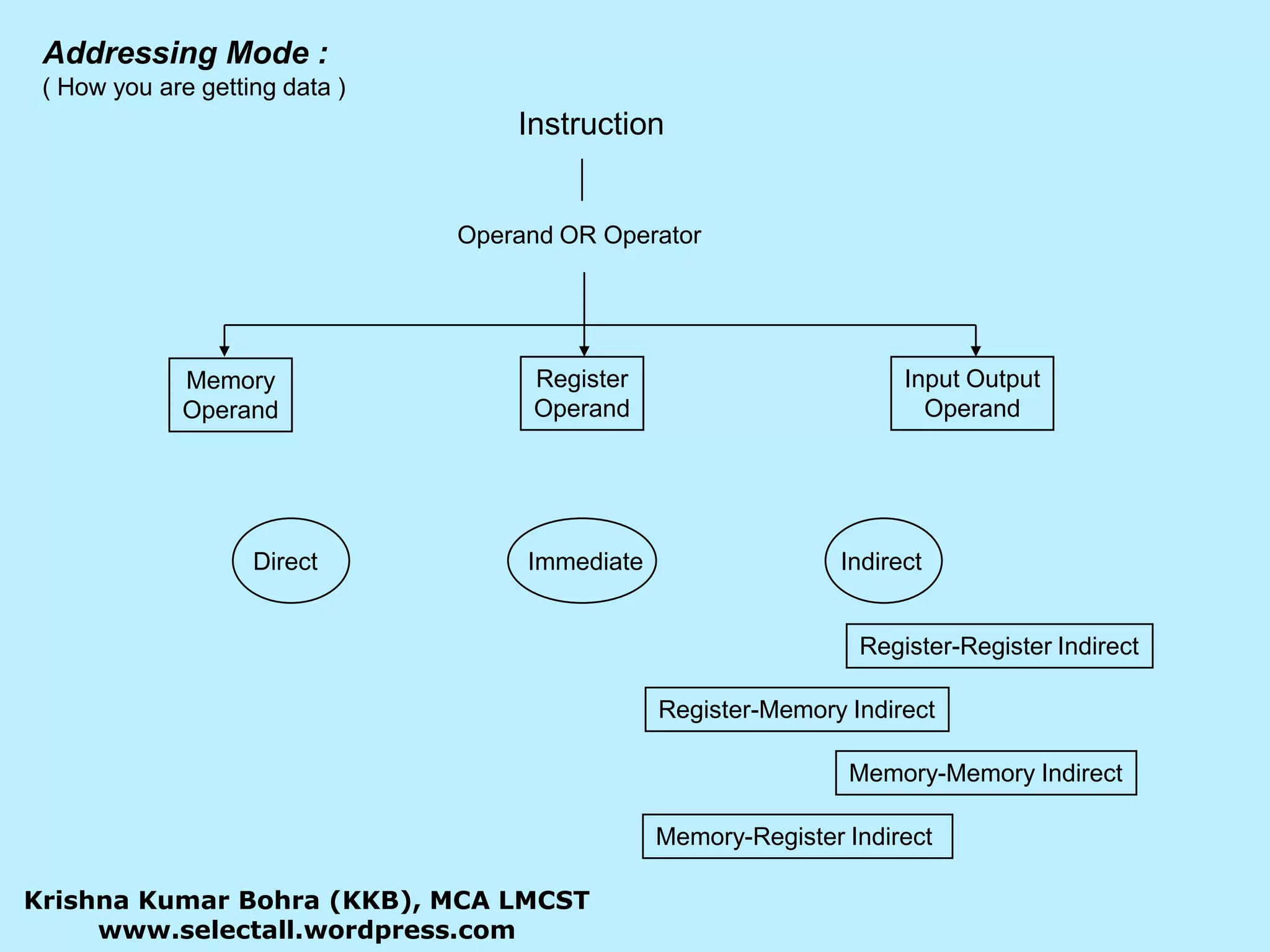
![Implied Mode : ( operand is at CPU’s register ) CMA Compliment ACC. STC Set CarryImmediate Mode : ( data is part of Instruction ) ADD 6 Add 6 to AccumulatorRegister Mode : ( Operand is available in GPR ) ADD B A A + B ADD A , B A A + B ADD R1 R0 R0 + R1Register Indirect Mode : IADD B A A + [M]B the content of Memory M whose address is given by register B must be Added to AKrishna Kumar Bohra (KKB), MCA LMCSTwww.selectall.wordpress.com](https://image.slidesharecdn.com/coa-1four-090729080935-phpapp02/75/Computer-Organisation-Part-4-15-2048.jpg)
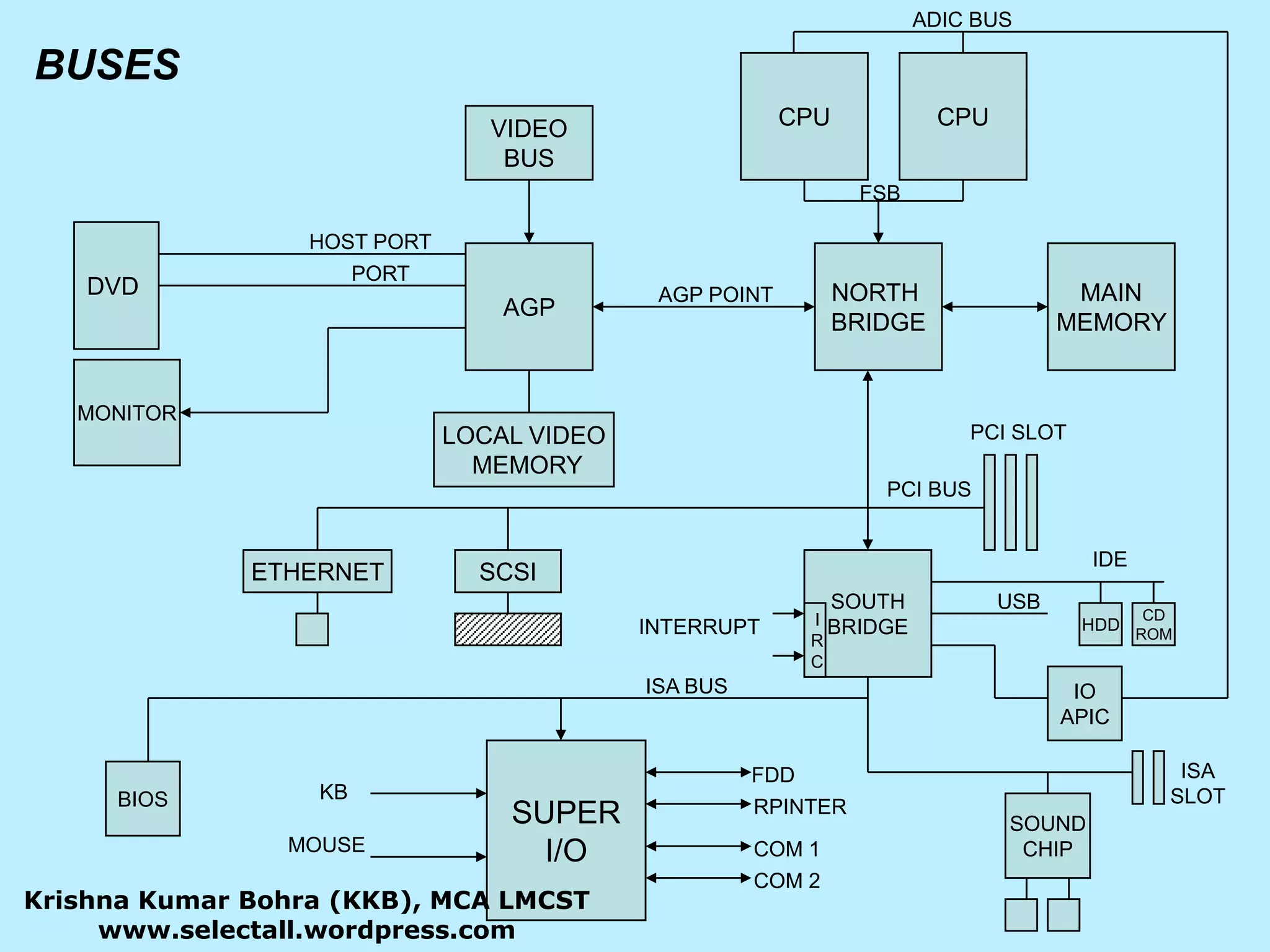
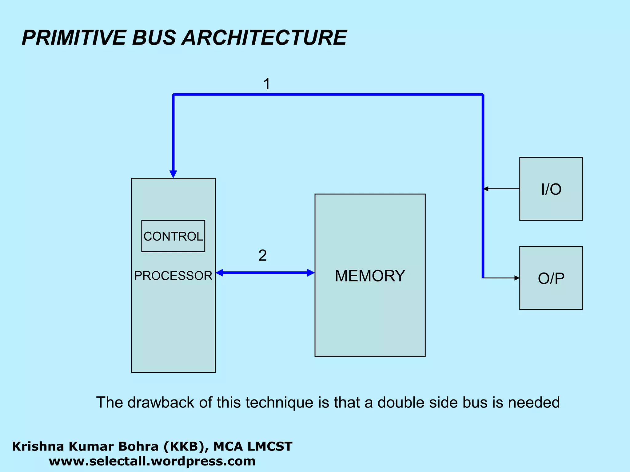
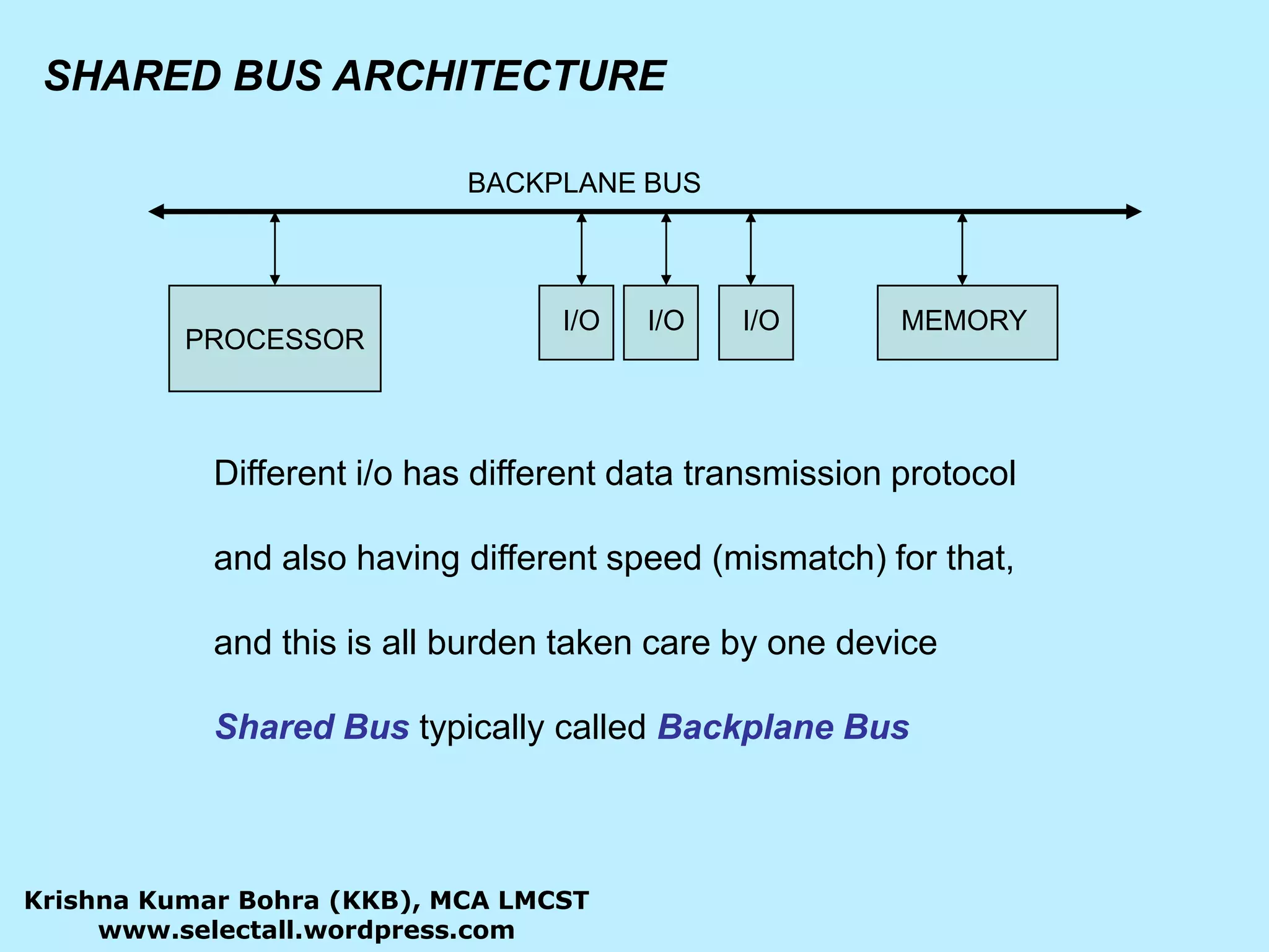
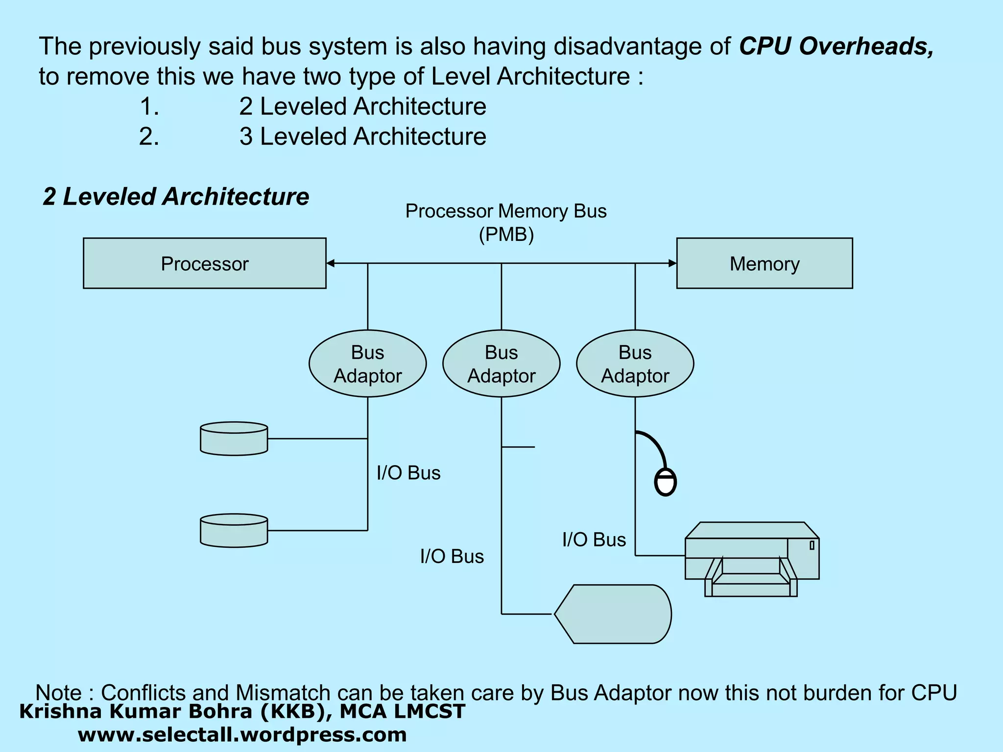
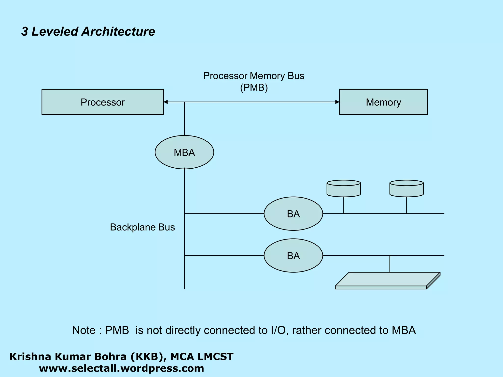
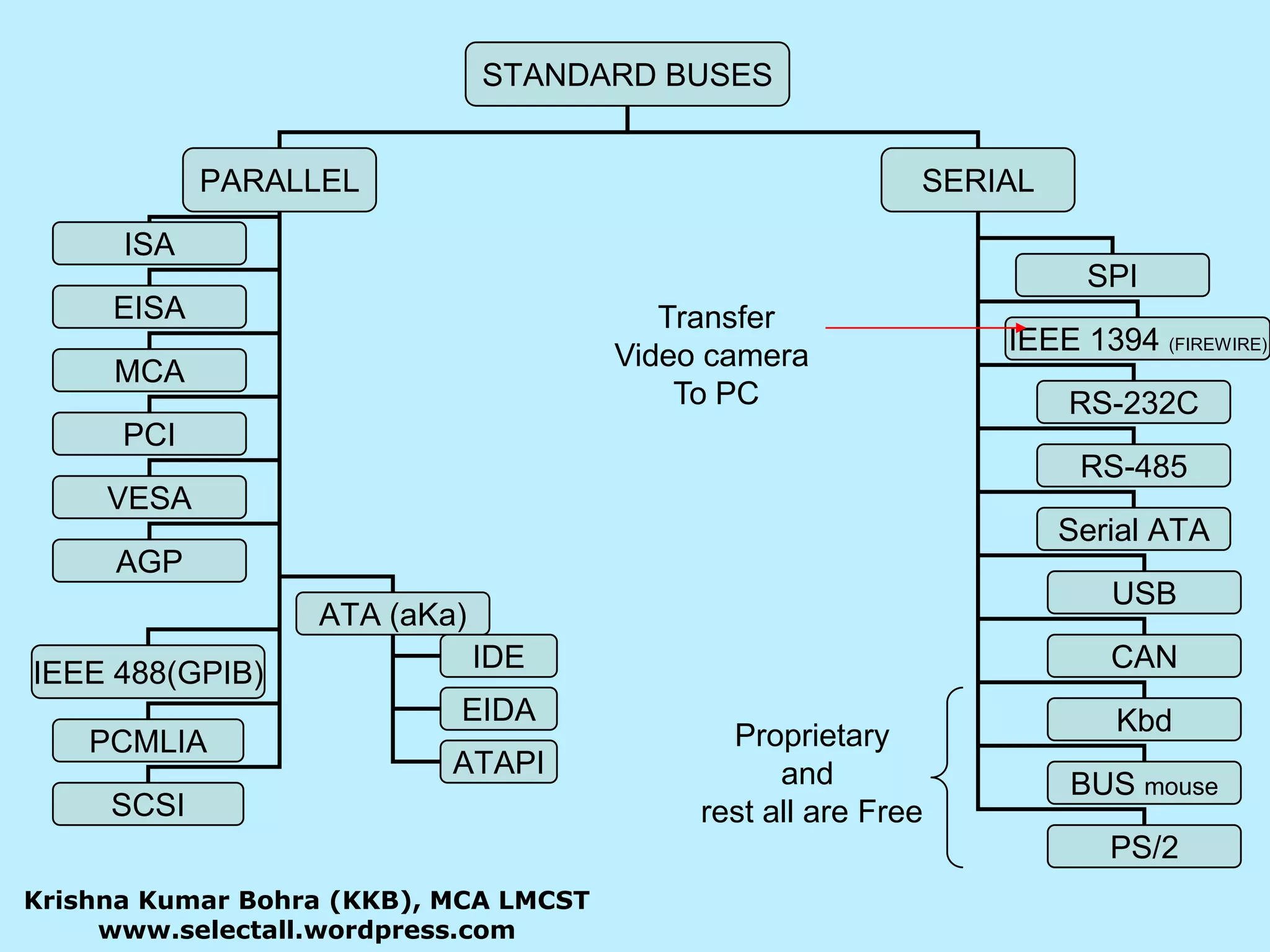
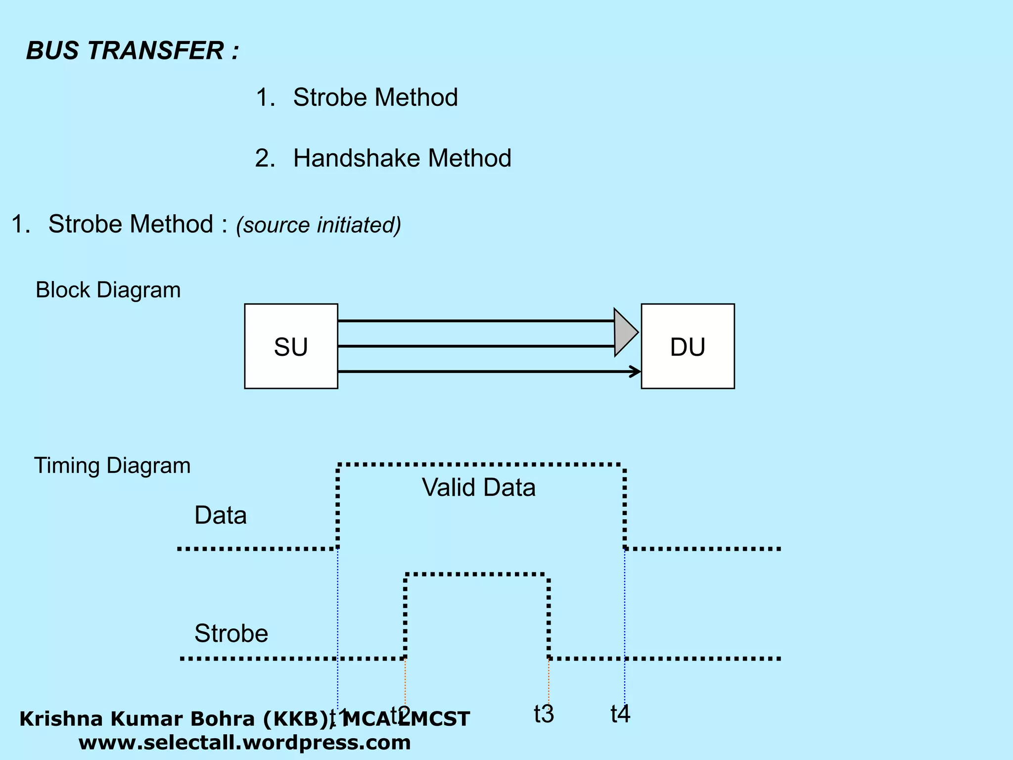


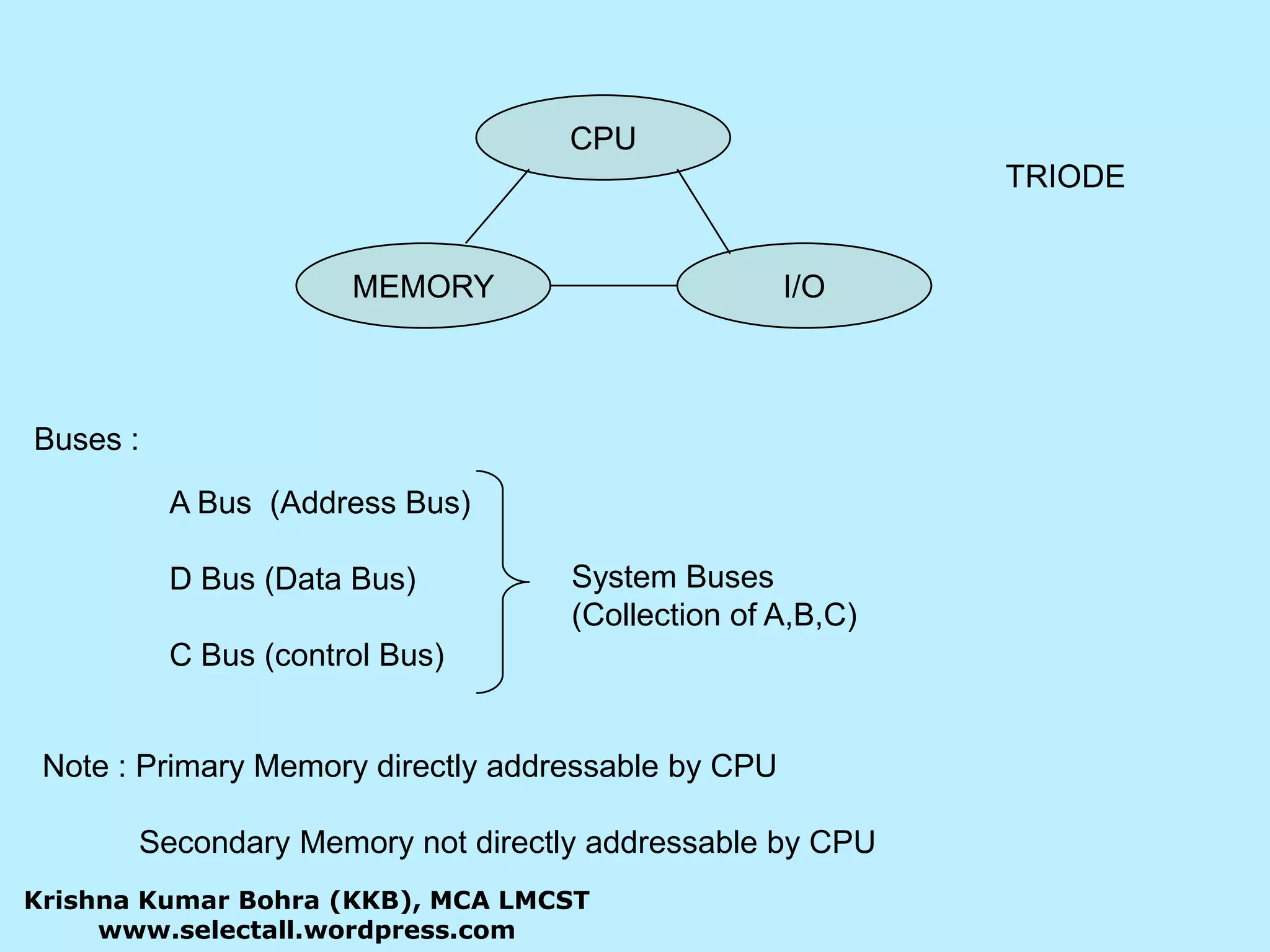
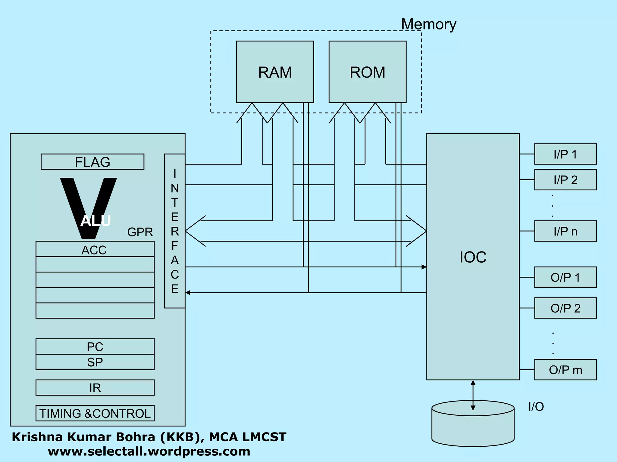
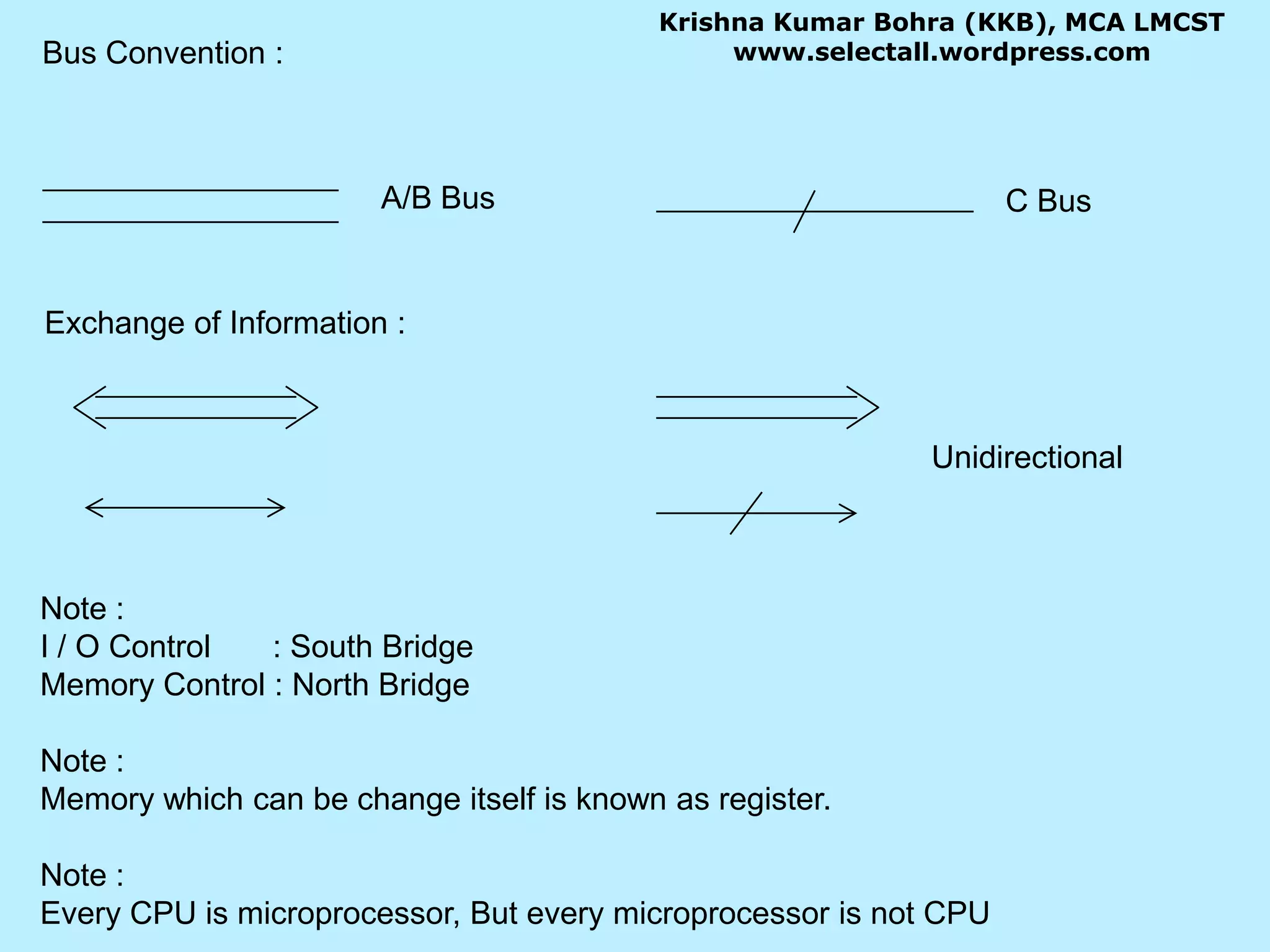
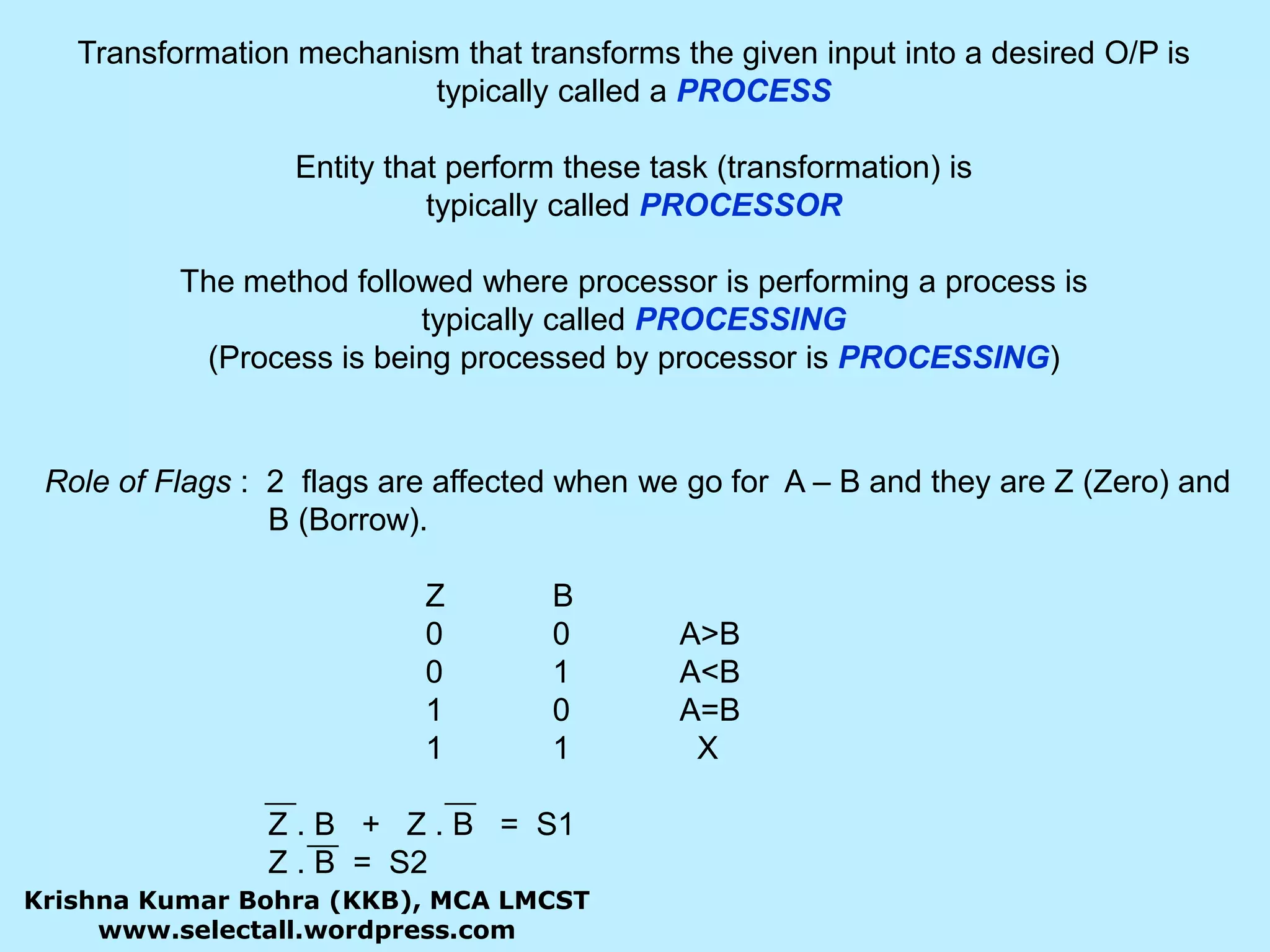
The document provides information about basic computer organization including the CPU, memory, buses, and input/output components. It discusses the CPU components like the ALU, registers, and control unit. It describes different types of memory like RAM, ROM, and I/O. It also explains the various buses used in a computer like the address bus, data bus, and control bus.