Download to read offline
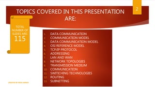
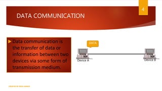


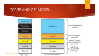


The document is a presentation on computer networks created by Rida Zaman, covering fundamental topics including data communication, communication models, OSI and TCP/IP reference models, addressing, LAN/WAN, network topologies, transmission media, and switching technologies. It details various network topologies like star, bus, and ring, discusses addressing methods in TCP/IP, and outlines communication methods such as simplex, half duplex, and full duplex. Additionally, it examines switching technologies, specifically circuit switching and packet switching.