This document provides an introduction to computer networking:
- It discusses the early history of computer networking from the 1960s to today. TCP/IP became the dominant standard over proprietary protocols.
- It defines common network types like LANs, MANs, and WANs based on geographical reach.
- It describes basic physical network topologies like full mesh, bus, and switched networks, noting tradeoffs in complexity and scalability.


![CHAPTER 1
Preface
This textbook came from a frustration of its main author. Many authors chose to write a textbook because there
are no textbooks in their field or because they are not satisfied with the existing textbooks. This frustration
has produced several excellent textbooks in the networking community. At a time when networking textbooks
were mainly theoretical, Douglas Comer chose to write a textbook entirely focused on the TCP/IP protocol suite
[Comer1988], a difficult choice at that time. He later extended his textbook by describing a complete TCP/IP
implementation, adding practical considerations to the theoretical descriptions in [Comer1988]. Richard Stevens
approached the Internet like an explorer and explained the operation of protocols by looking at all the packets
that were exchanged on the wire [Stevens1994]. Jim Kurose and Keith Ross reinvented the networking textbooks
by starting from the applications that the students use and later explained the Internet protocols by removing one
layer after the other [KuroseRoss09].
The frustrations that motivated this book are different. When I started to teach networking in the late 1990s,
students were already Internet users, but their usage was limited. Students were still using reference textbooks and
spent time in the library. Today’s students are completely different. They are avid and experimented web users
who find lots of information on the web. This is a positive attitude since they are probably more curious than
their predecessors. Thanks to the information that is available on the Internet, they can check or obtain additional
information about the topics explained by their teachers. This abundant information creates several challenges for
a teacher. Until the end of the nineteenth century, a teacher was by definition more knowledgeable than his students
and it was very difficult for the students to verify the lessons given by their teachers. Today, given the amount
of information available at the fingertips of each student through the Internet, verifying a lesson or getting more
information about a given topic is sometimes only a few clicks away. Websites such as wikipedia provide lots of
information on various topics and students often consult them. Unfortunately, the organisation of the information
on these websites is not well suited to allow students to learn from them. Furthermore, there are huge differences
in the quality and depth of the information that is available for different topics.
The second reason is that the computer networking community is a strong participant in the open-source move-
ment. Today, there are high-quality and widely used open-source implementations for most networking protocols.
This includes the TCP/IP implementations that are part of linux, freebsd or the uIP stack running on 8bits con-
trollers, but also servers such as bind, unbound, apache or sendmail and implementations of routing protocols such
as xorp or quagga . Furthermore, the documents that define almost all of the Internet protocols have been devel-
oped within the Internet Engineering Task Force (IETF) using an open process. The IETF publishes its protocol
specifications in the publicly available RFC and new proposals are described in Internet drafts.
This open textbook aims to fill the gap between the open-source implementations and the open-source network
specifications by providing a detailed but pedagogical description of the key principles that guide the operation of
the Internet. The book is released under a creative commons licence. Such an open-source license is motivated
by two reasons. The first is that we hope that this will allow many students to use the book to learn computer
networks. The second is that I hope that other teachers will reuse, adapt and improve it. Time will tell if it is
possible to build a community of contributors to improve and develop the book further. As a starting point, the
first release contains all the material for a one-semester first upper undergraduate or a graduate networking course.
As of this writing, most of the text has been written by Olivier Bonaventure. Laurent Vanbever, Virginie Van den
3
Saylor URL: http://www.saylor.org/courses/cs402/ The Saylor Foundation](https://image.slidesharecdn.com/computer-networking-principles-bonaventure-1-30-31-otc1-150825141809-lva1-app6891/75/Computer-networking-principles-bonaventure-1-30-31-otc1-7-2048.jpg)
![CHAPTER 2
Introduction
When the first computers were built during the second world war, they were expensive and isolated. However,
after about twenty years, as their prices gradually decreased, the first experiments began to connect computers
together. In the early 1960s, researchers including Paul Baran, Donald Davies or Joseph Licklider independently
published the first papers describing the idea of building computer networks [Baran] [Licklider1963] . Given
the cost of computers, sharing them over a long distance was an interesting idea. In the US, the ARPANET
started in 1969 and continued until the mid 1980s [LCCD09]. In France, Louis Pouzin developed the Cyclades
network [Pouzin1975]. Many other research networks were built during the 1970s [Moore]. At the same time,
the telecommunication and computer industries became interested in computer networks. The telecommunication
industry bet on the X25. The computer industry took a completely different approach by designing Local Area
Networks (LAN). Many LAN technologies such as Ethernet or Token Ring were designed at that time. During
the 1980s, the need to interconnect more and more computers led most computer vendors to develop their own
suite of networking protocols. Xerox developed [XNS] , DEC chose DECNet [Malamud1991] , IBM developed
SNA [McFadyen1976] , Microsoft introduced NetBIOS [Winston2003] , Apple bet on Appletalk [SAO1990] . In
the research community, ARPANET was decommissioned and replaced by TCP/IP [LCCD09] and the reference
implementation was developed inside BSD Unix [McKusick1999]. Universities who were already running Unix
could thus adopt TCP/IP easily and vendors of Unix workstations such as Sun or Silicon Graphics included TCP/IP
in their variant of Unix. In parallel, the ISO, with support from the governments, worked on developing an open
1
Suite of networking protocols. In the end, TCP/IP became the de facto standard that is not only used within the
research community. During the 1990s and the early 2000s, the growth of the usage of TCP/IP continued, and
today proprietary protocols are seldom used. As shown by the figure below, that provides the estimation of the
number of hosts attached to the Internet, the Internet has sustained large growth throughout the last 20+ years.
Figure 2.1: Estimation of the number of hosts on the Internet
1 Open in ISO terms was in contrast with the proprietary protocol suites whose specification was not always publicly available. The US
government even mandated the usage of the OSI protocols (see RFC 1169), but this was not sufficient to encourage all users to switch to the
OSI protocol suite that was considered by many as too complex compared to other protocol suites.
5
Saylor URL: http://www.saylor.org/courses/cs402/ The Saylor Foundation](https://image.slidesharecdn.com/computer-networking-principles-bonaventure-1-30-31-otc1-150825141809-lva1-app6891/75/Computer-networking-principles-bonaventure-1-30-31-otc1-9-2048.jpg)
![Computer Networking : Principles, Protocols and Practice, Release 0.25
Recent estimations of the number of hosts attached to the Internet show a continuing growth since 20+ years.
However, although the number of hosts attached to the Internet is high, it should be compared to the number
of mobile phones that are in use today. More and more of these mobile phones will be connected to the Inter-
net. Furthermore, thanks to the availability of TCP/IP implementations requiring limited resources such as uIP
[Dunkels2003], we can expect to see a growth of TCP/IP enabled embedded devices.
Figure 2.2: Estimation of the number of mobile phones
Before looking at the services provided by computer networks, it is useful to agree on some terminology that
is widely used in networking literature. First of all, computer networks are often classified in function of the
geographical area that they cover
• LAN : a local area network typically interconnects hosts that are up to a few or maybe a few tens of kilome-
ters apart.
• MAN : a metropolitan area network typically interconnects devices that are up to a few hundred kilometers
apart
• WAN : a wide area network interconnect hosts that can be located anywhere on Earth 2
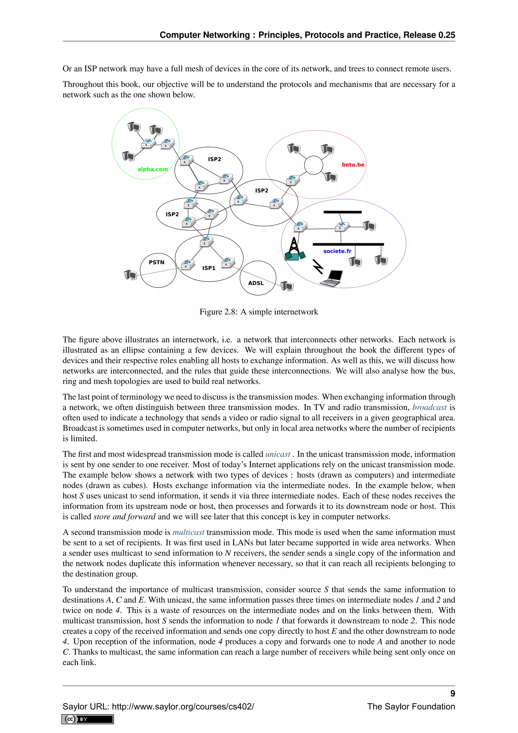
Another classification of computer networks is based on their physical topology. In the following figures, physical
links are represented as lines while boxes show computers or other types of networking equipment.
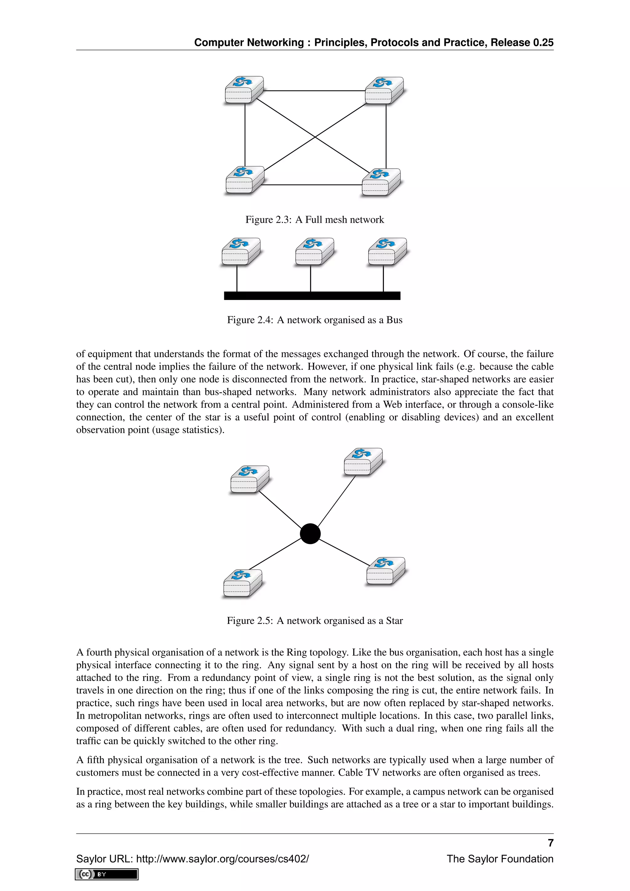
Computer networks are used to allow several hosts to exchange information between themselves. To allow any
host to send messages to any other host in the network, the easiest solution is to organise them as a full-mesh, with
a direct and dedicated link between each pair of hosts. Such a physical topology is sometimes used, especially
when high performance and high redundancy is required for a small number of hosts. However, it has two major
drawbacks :
• for a network containing n hosts, each host must have n-1 physical interfaces. In practice, the number of
physical interfaces on a node will limit the size of a full-mesh network that can be built
• for a network containing n hosts, n×(n−1)
2 links are required. This is possible when there are a few nodes
in the same room, but rarely when they are located several kilometers apart
The second possible physical organisation, which is also used inside computers to connect different extension
cards, is the bus. In a bus network, all hosts are attached to a shared medium, usually a cable through a single
interface. When one host sends an electrical signal on the bus, the signal is received by all hosts attached to the bus.
A drawback of bus-based networks is that if the bus is physically cut, then the network is split into two isolated
networks. For this reason, bus-based networks are sometimes considered to be difficult to operate and maintain,
especially when the cable is long and there are many places where it can break. Such a bus-based topology was
used in early Ethernet networks.
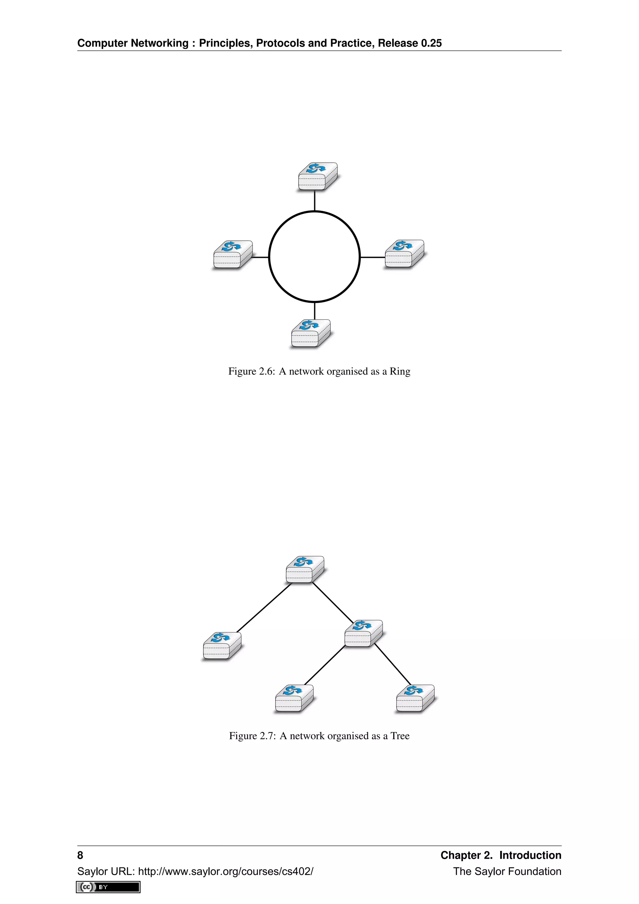
A third organisation of a computer network is a star topology. In such topologies, hosts have a single physical
interface and there is one physical link between each host and the center of the star. The node at the center of
the star can be either a piece of equipment that amplifies an electrical signal, or an active device, such as a piece
2 In this book, we focus on networks that are used on Earth. These networks sometimes include satellite links. Besides the network
technologies that are used on Earth, researchers develop networking techniques that could be used between nodes located on different planets.
Such an Inter Planetary Internet requires different techniques than the ones discussed in this book. See RFC 4838 and the references therein
for information about these techniques.
6 Chapter 2. Introduction
Saylor URL: http://www.saylor.org/courses/cs402/ The Saylor Foundation](https://image.slidesharecdn.com/computer-networking-principles-bonaventure-1-30-31-otc1-150825141809-lva1-app6891/75/Computer-networking-principles-bonaventure-1-30-31-otc1-10-2048.jpg)
![Computer Networking : Principles, Protocols and Practice, Release 0.25
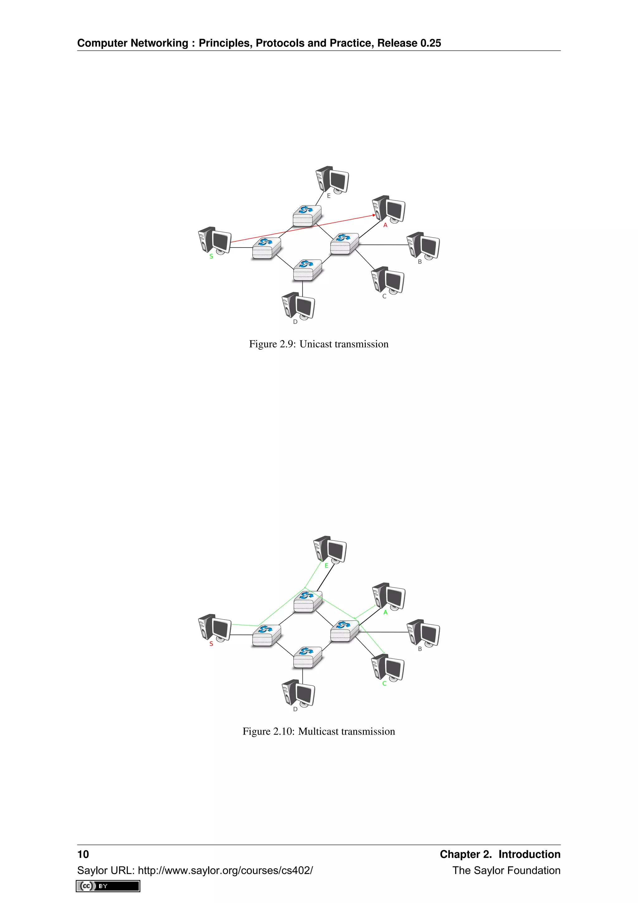
The last transmission mode is the anycast transmission mode. It was initially defined in RFC 1542. In this
transmission mode, a set of receivers is identified. When a source sends information towards this set of receivers,
the network ensures that the information is delivered to one receiver that belongs to this set. Usually, the receiver
closest to the source is the one that receives the information sent by this particular source. The anycast transmission
mode is useful to ensure redundancy, as when one of the receivers fails, the network will ensure that information
will be delivered to another receiver belonging to the same group. However, in practice supporting the anycast
transmission mode can be difficult.
A
*
S
*
*
B
Figure 2.11: Anycast transmission
In the example above, the three hosts marked with * are part of the same anycast group. When host S sends
information to this anycast group, the network ensures that it will reach one of the members of the anycast group.
The dashed lines show a possible delivery via nodes 1, 2 and 4. A subsequent anycast transmission from host
S to the same anycast group could reach the host attached to intermediate node 3 as shown by the plain line.
An anycast transmission reaches a member of the anycast group that is chosen by the network in function of the
current network conditions.
2.1 Services and protocols
An important aspect to understand before studying computer networks is the difference between a service and a
protocol.
In order to understand the difference between the two, it is useful to start with real world examples. The traditional
Post provides a service where a postman delivers letters to recipients. The Post defines precisely which types of
letters (size, weight, etc) can be delivered by using the Standard Mail service. Furthermore, the format of the
envelope is specified (position of the sender and recipient addresses, position of the stamp). Someone who wants
to send a letter must either place the letter at a Post Office or inside one of the dedicated mailboxes. The letter
will then be collected and delivered to its final recipient. Note that for the regular service the Post usually does
not guarantee the delivery of each particular letter, some letters may be lost, and some letters are delivered to the
wrong mailbox. If a letter is important, then the sender can use the registered service to ensure that the letter will
be delivered to its recipient. Some Post services also provide an acknowledged service or an express mail service
that is faster than the regular service.
In computer networks, the notion of service is more formally defined in [X200] . It can be better understood by
considering a computer network, whatever its size or complexity, as a black box that provides a service to users ,
as shown in the figure below. These users could be human users or processes running on a computer system.
Many users can be attached to the same service provider. Through this provider, each user must be able to
exchange messages with any other user. To be able to deliver these messages, the service provider must be able
to unambiguously identify each user. In computer networks, each user is identified by a unique address, we will
discuss later how these addresses are built and used. At this point, and when considering unicast transmission, the
main characteristic of these addresses is that they are unique. Two different users attached to the network cannot
use the same address.
2.1. Services and protocols 11
Saylor URL: http://www.saylor.org/courses/cs402/ The Saylor Foundation](https://image.slidesharecdn.com/computer-networking-principles-bonaventure-1-30-31-otc1-150825141809-lva1-app6891/75/Computer-networking-principles-bonaventure-1-30-31-otc1-15-2048.jpg)
![Computer Networking : Principles, Protocols and Practice, Release 0.25
User A User B
Service provider ("the network")
Service Access Point
Primitives
Figure 2.12: Users and service provider
Throughout this book, we will define a service as a set of capabilities provided by a system (and its underlying
elements) to its user. A user interacts with a service through a service access point. Note that as shown in the figure
above, users interact with one service provider. In practice, the service provider is distributed over several hosts,
but these are implementation details that are not important at this stage. These interactions between a user and a
service provider are expressed in [X200] by using primitives, as show in the figure below. These primitives are
an abstract representation of the interactions between a user and a service provider. In practice, these interactions
could be implemented as system calls for example.
User A User B
Service provider ("the network")
X.indicationX.responseX.confirmX.request
Figure 2.13: The four types of primitives
Four types of primitives are defined :
• X.request. This type of primitive corresponds to a request issued by a user to a service provider
• X.indication. This type of primitive is generated by the network provider and delivered to a user (often
related to an earlier and remote X.request primitive)
• X.response. This type of primitive is generated by a user to answer to an earlier X.indication primitive
• X.confirm. This type of primitive is delivered by the service provide to confirm to a user that a previous
X.request primitive has been successfully processed.
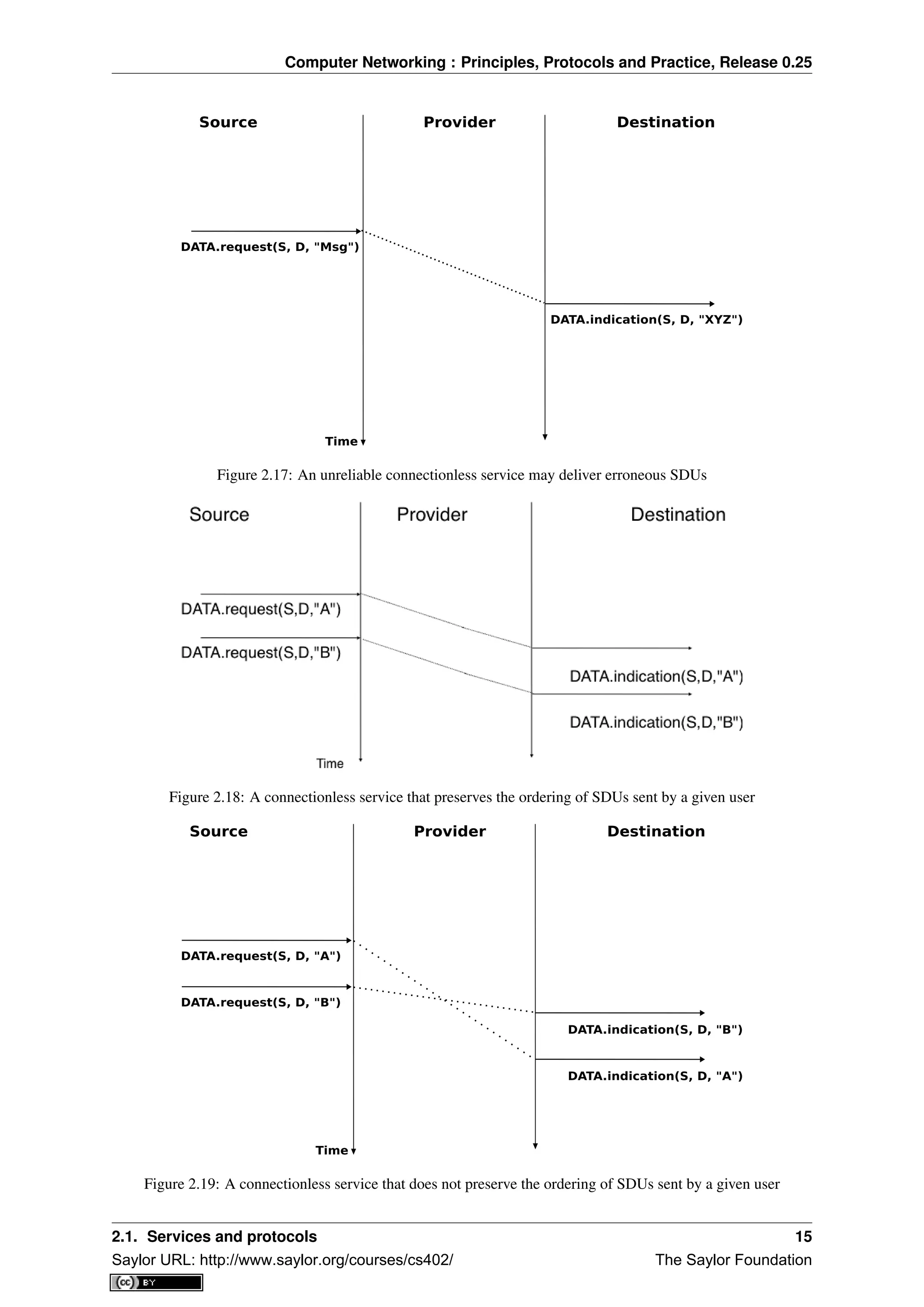
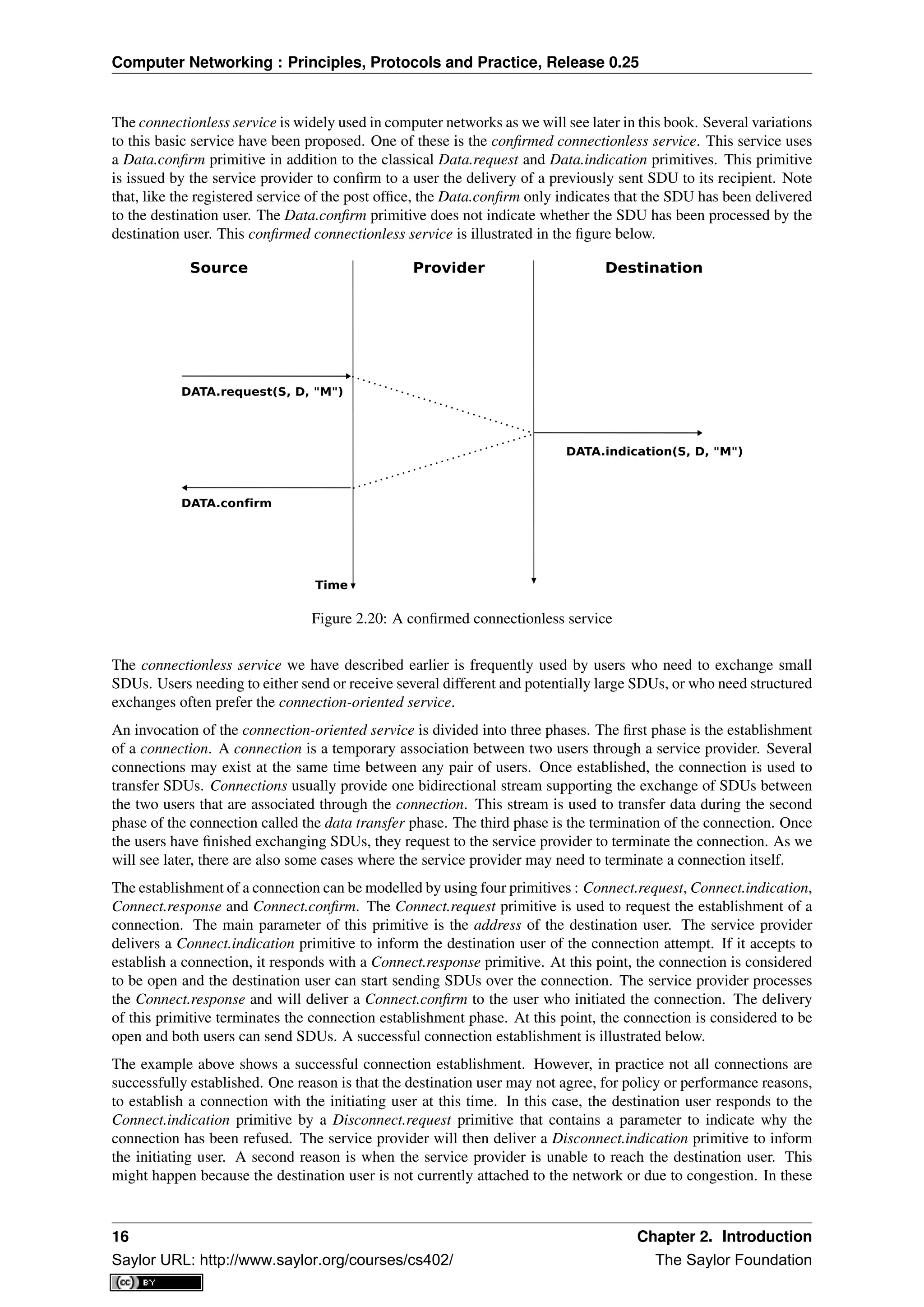
Primitives can be combined to model different types of services. The simplest service in computer networks is
called the connectionless service 3
. This service can be modelled by using two primitives :
• Data.request(source,destination,SDU). This primitive is issued by a user that specifies, as parameters, its
(source) address, the address of the recipient of the message and the message itself. We will use Service
Data Unit (SDU) to name the message that is exchanged transparently between two users of a service.
• Data.indication(source,destination,SDU). This primitive is delivered by a service provider to a user. It
contains as parameters a Service Data Unit as well as the addresses of the sender and the destination users.
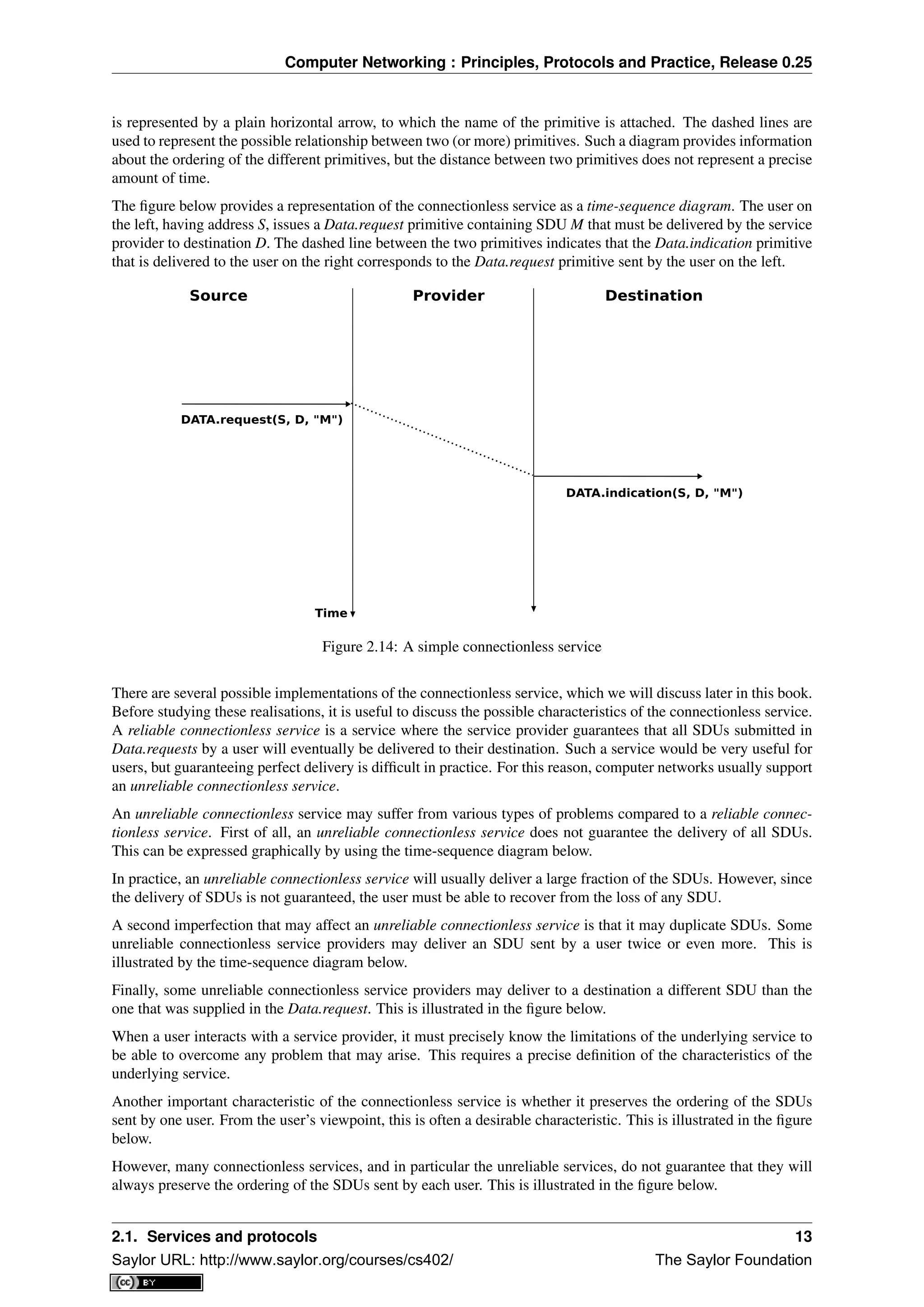
When discussing the service provided in a computer network, it is often useful to be able to describe the inter-
actions between the users and the provider graphically. A frequently used representation is the time-sequence
diagram. In this chapter and later throughout the book, we will often use diagrams such as the figure below. A
time-sequence diagram describes the interactions between two users and a service provider. By convention, the
users are represented in the left and right parts of the diagram while the service provider occupies the middle of the
diagram. In such a time-sequence diagram, time flows from the top, to the bottom of the diagram. Each primitive
3 This service is called the connectionless service because there is no need to create a connection before transmitting any data in contrast
with the connection-oriented service.
12 Chapter 2. Introduction
Saylor URL: http://www.saylor.org/courses/cs402/ The Saylor Foundation](https://image.slidesharecdn.com/computer-networking-principles-bonaventure-1-30-31-otc1-150825141809-lva1-app6891/75/Computer-networking-principles-bonaventure-1-30-31-otc1-16-2048.jpg)
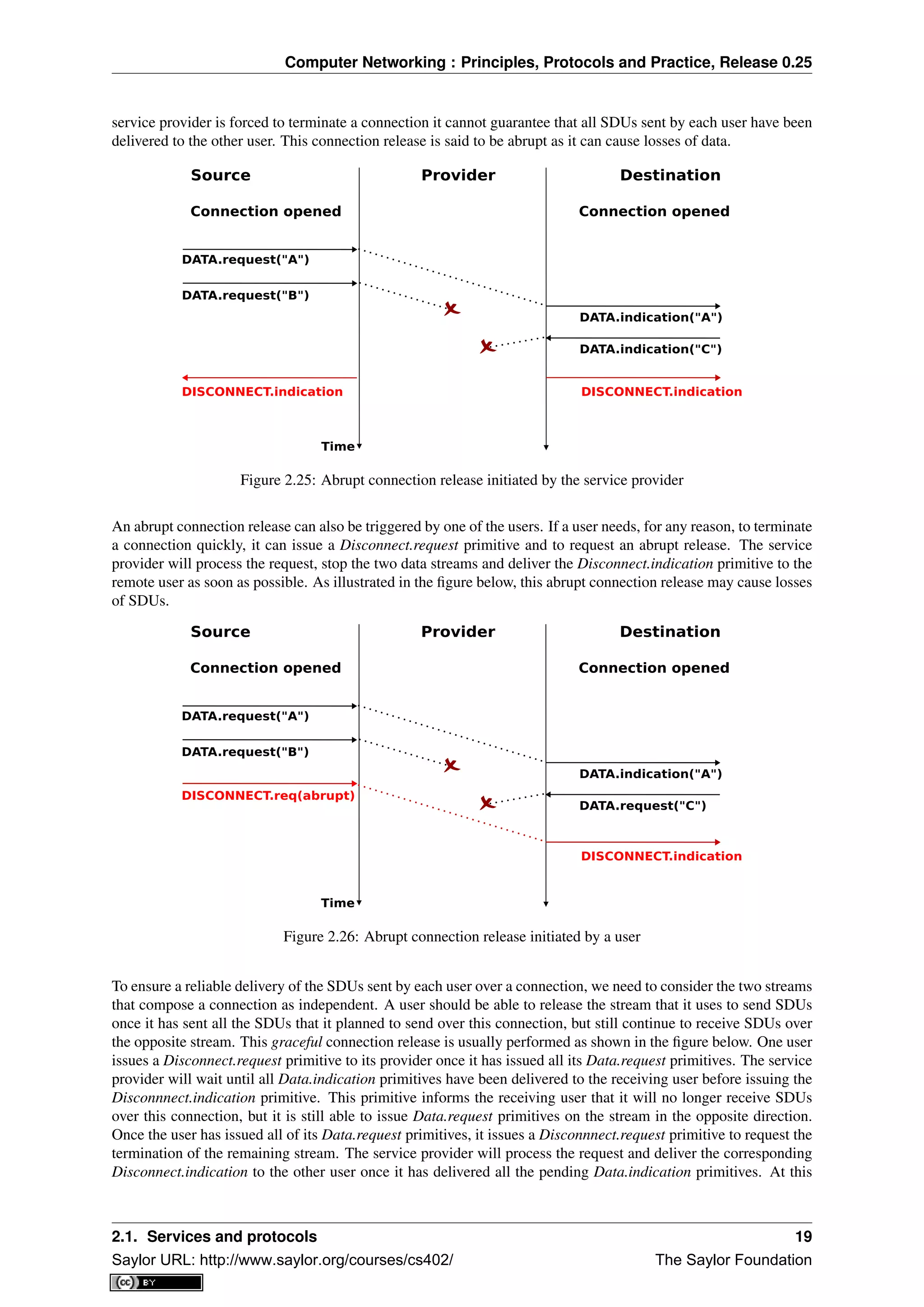
![Computer Networking : Principles, Protocols and Practice, Release 0.25
point, all data has been delivered and the two streams have been released successfully and the connection is
completely closed.
Source Provider Destination
Time
DATA.request("A")
Source -> Destination
connection closed
Connection opened Connection opened
DATA.request("B") DATA.request("C")
DATA.indication("A")
DATA.indication("B")
DISCONNECT.req(graceful)
DISCONNECT.ind(graceful)
DATA.indication("C")
DATA.indication("D")
DATA.request("D")
DISCONNECT.ind(graceful)
DISCONNECT.req(graceful)
Connection closed Connection closed
Figure 2.27: Graceful connection release
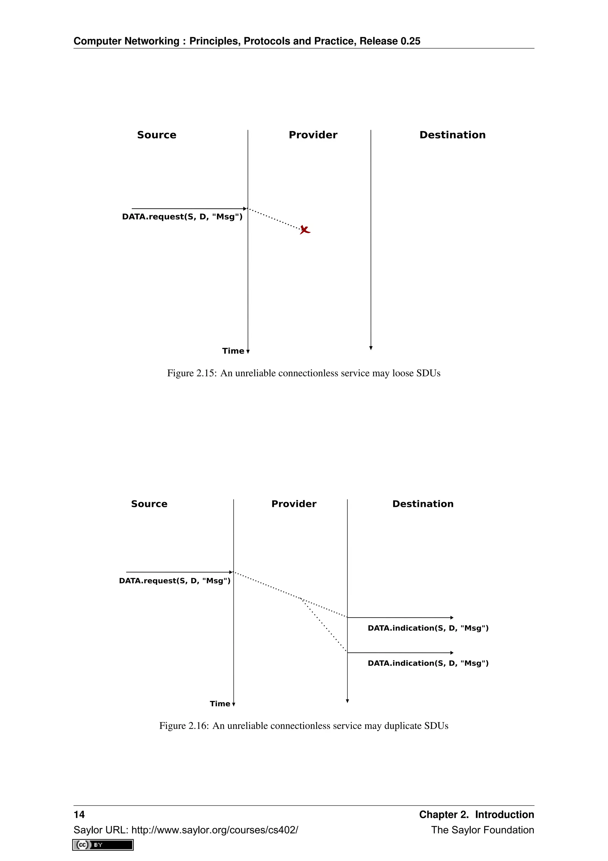
Note: Reliability of the connection-oriented service
An important point to note about the connection-oriented service is its reliability. A connection-oriented service
can only guarantee the correct delivery of all SDUs provided that the connection has been released gracefully. This
implies that while the connection is active, there is no guarantee for the actual delivery of the SDUs exchanged as
the connection may need to be released abruptly at any time.
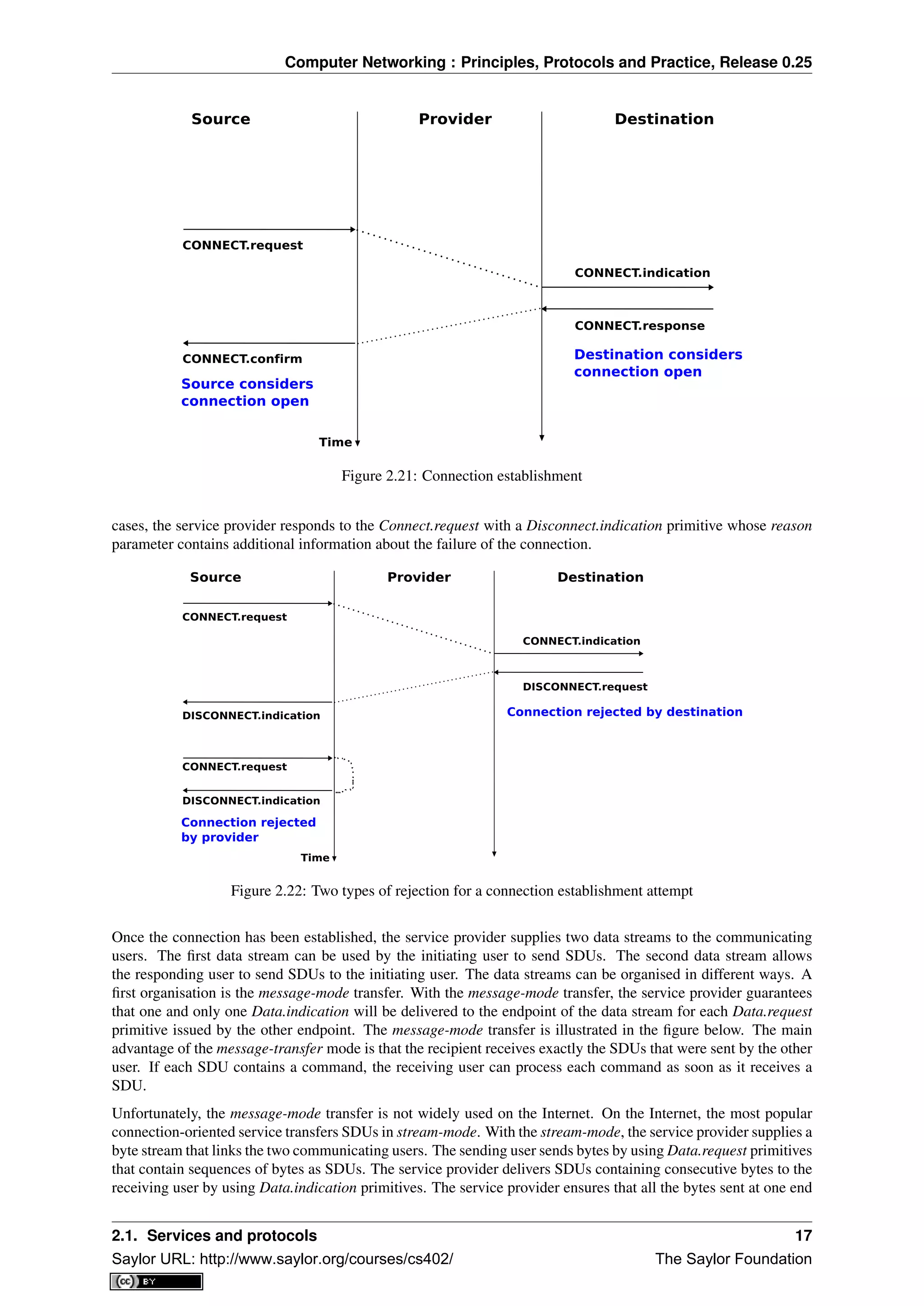
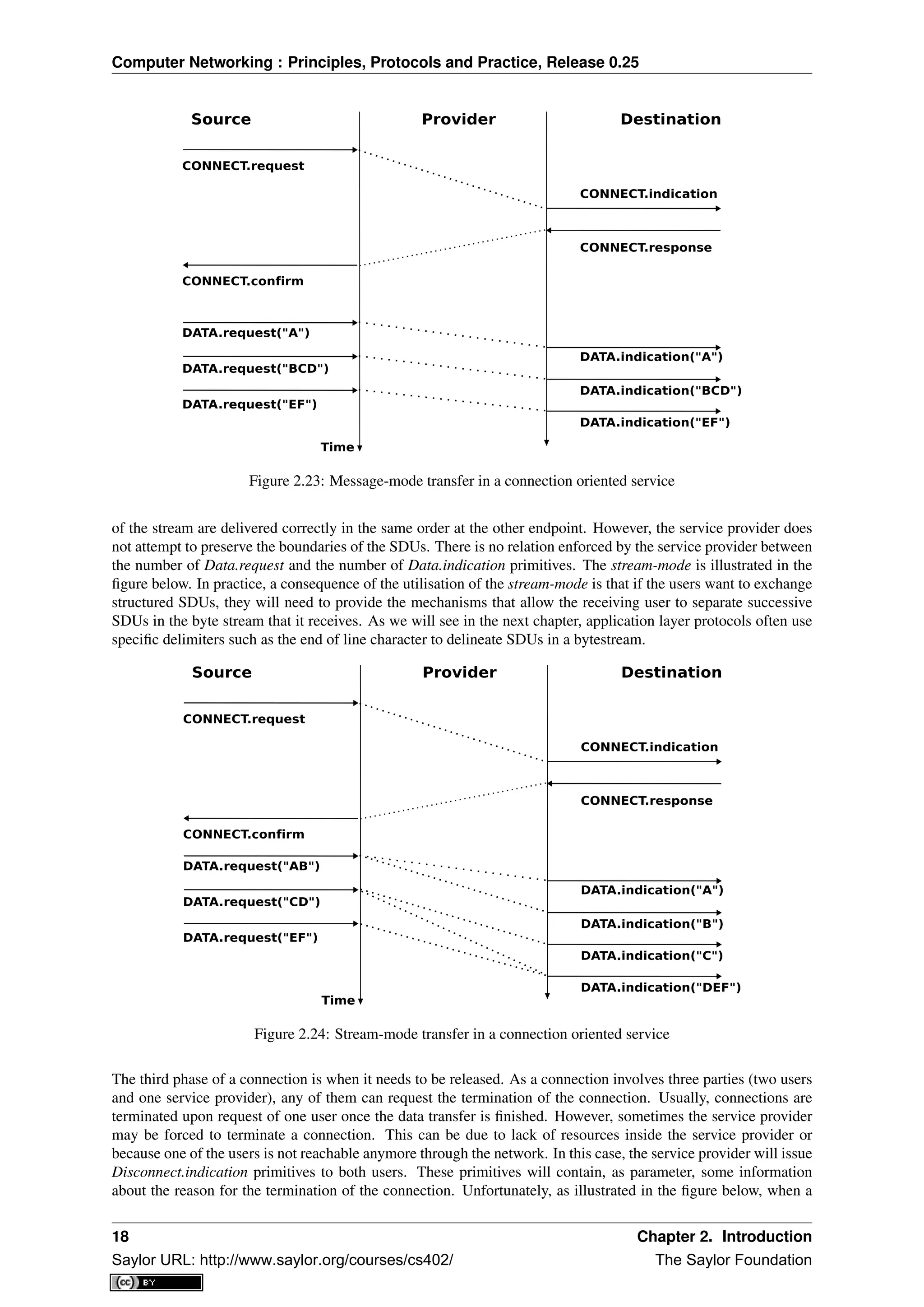
2.2 The reference models
Given the growing complexity of computer networks, during the 1970s network researchers proposed various
reference models to facilitate the description of network protocols and services. Of these, the Open Systems
Interconnection (OSI) model [Zimmermann80] was probably the most influential. It served as the basis for the
standardisation work performed within the ISO to develop global computer network standards. The reference
model that we use in this book can be considered as a simplified version of the OSI reference model 4
.
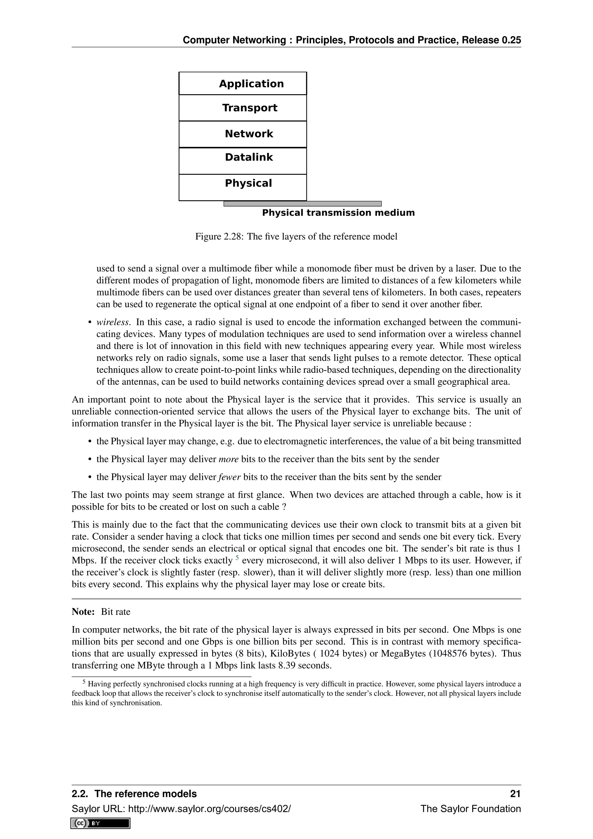
2.2.1 The five layers reference model
Our reference model is divided into five layers, as shown in the figure below.
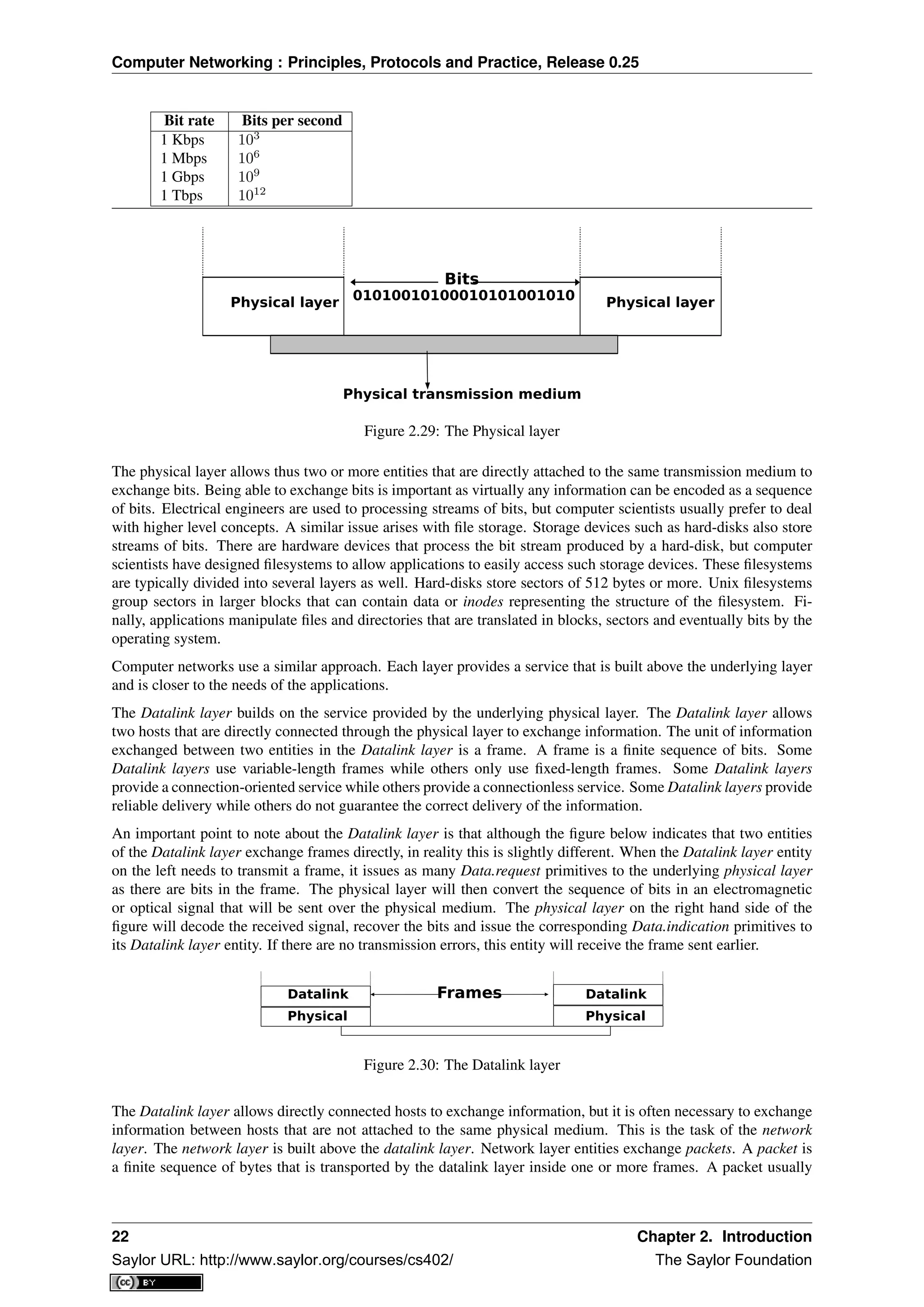
Starting from the bottom, the first layer is the Physical layer. Two communicating devices are linked through a
physical medium. This physical medium is used to transfer an electrical or optical signal between two directly
connected devices. Several types of physical mediums are used in practice :
• electrical cable. Information can be transmitted over different types of electrical cables. The most common
ones are the twisted pairs that are used in the telephone network, but also in enterprise networks and coaxial
cables. Coaxial cables are still used in cable TV networks, but are no longer used in enterprise networks.
Some networking technologies operate over the classical electrical cable.
• optical fiber. Optical fibers are frequently used in public and enterprise networks when the distance be-
tween the communication devices is larger than one kilometer. There are two main types of optical fibers
: multimode and monomode. Multimode is much cheaper than monomode fiber because a LED can be
4 An interesting historical discussion of the OSI-TCP/IP debate may be found in [Russel06]
20 Chapter 2. Introduction
Saylor URL: http://www.saylor.org/courses/cs402/ The Saylor Foundation](https://image.slidesharecdn.com/computer-networking-principles-bonaventure-1-30-31-otc1-150825141809-lva1-app6891/75/Computer-networking-principles-bonaventure-1-30-31-otc1-24-2048.jpg)
![Computer Networking : Principles, Protocols and Practice, Release 0.25
contains information about its origin and its destination, and usually passes through several intermediate devices
called routers on its way from its origin to its destination.
Physical layer
Datalink
Network
Physical layer
Datalink
Network
Physical layer
Datalink
NetworkPackets Packets
Figure 2.31: The network layer
Most realisations of the network layer, including the internet, do not provide a reliable service. However, many
applications need to exchange information reliably and so using the network layer service directly would be
very difficult for them. Ensuring the reliable delivery of the data produced by applications is the task of the
transport layer. Transport layer entities exchange segments. A segment is a finite sequence of bytes that are
transported inside one or more packets. A transport layer entity issues segments (or sometimes part of segments)
as Data.request to the underlying network layer entity.
There are different types of transport layers. The most widely used transport layers on the Internet are TCP
,that provides a reliable connection-oriented bytestream transport service, and UDP ,that provides an unreliable
connection-less transport service.
Physical layer
Datalink
Network
Physical layer
Datalink
Network
Transport
Physical layer
Datalink
Network
TransportSegments
Figure 2.32: The transport layer
The upper layer of our architecture is the Application layer. This layer includes all the mechanisms and data
structures that are necessary for the applications. We will use Application Data Unit (ADU) to indicate the data
exchanged between two entities of the Application layer.
Physical layer
Datalink
Network
Physical layer
Datalink
Network
Transport
Physical layer
Datalink
Network
Transport
ADUApplication Application
Figure 2.33: The Application layer
2.2.2 The TCP/IP reference model
In contrast with OSI, the TCP/IP community did not spend a lot of effort defining a detailed reference model; in
fact, the goals of the Internet architecture were only documented after TCP/IP had been deployed [Clark88]. RFC
1122 , which defines the requirements for Internet hosts, mentions four different layers. Starting from the top,
these are :
• an Application layer
• a Transport layer
• an Internet layer which is equivalent to the network layer of our reference model
• a Link layer which combines the functionalities of the physical and datalink layers of our five-layer reference
model
Besides this difference in the lower layers, the TCP/IP reference model is very close to the five layers that we use
throughout this document.
2.2. The reference models 23
Saylor URL: http://www.saylor.org/courses/cs402/ The Saylor Foundation](https://image.slidesharecdn.com/computer-networking-principles-bonaventure-1-30-31-otc1-150825141809-lva1-app6891/75/Computer-networking-principles-bonaventure-1-30-31-otc1-27-2048.jpg)
![Computer Networking : Principles, Protocols and Practice, Release 0.25
2.2.3 The OSI reference model
Compared to the five layers reference model explained above, the OSI reference model defined in [X200] is
divided in seven layers. The four lower layers are similar to the four lower layers described above. The OSI
reference model refined the application layer by dividing it in three layers :
• the Session layer. The Session layer contains the protocols and mechanisms that are necessary to organize
and to synchronize the dialogue and to manage the data exchange of presentation layer entities. While one
of the main functions of the transport layer is to cope with the unreliability of the network layer, the session’s
layer objective is to hide the possible failures of transport-level connections to the upper layer higher. For
this, the Session Layer provides services that allow to establish a session-connection, to support orderly data
exchange (including mechanisms that allow to recover from the abrupt release of an underlying transport
connection), and to release the connection in an orderly manner.
• the Presentation layer was designed to cope with the different ways of representing information on comput-
ers. There are many differences in the way computer store information. Some computers store integers as
32 bits field, others use 64 bits field and the same problem arises with floating point number. For textual
information, this is even more complex with the many different character codes that have been used 6
. The
situation is even more complex when considering the exchange of structured information such as database
records. To solve this problem, the Presentation layer contains provides for a common representation of the
data transferred. The ASN.1 notation was designed for the Presentation layer and is still used today by some
protocols.
• the Application layer that contains the mechanisms that do not fit in neither the Presentation nor the Session
layer. The OSI Application layer was itself further divided in several generic service elements.
Note: Where are the missing layers in TCP/IP reference model ?
The TCP/IP reference places the Presentation and the Session layers implicitly in the Application layer. The
main motivations for simplifying the upper layers in the TCP/IP reference model were pragmatic. Most Internet
applications started as prototypes that evolved and were later standardised. Many of these applications assumed
that they would be used to exchange information written in American English and for which the 7 bits US-ASCII
character code was sufficient. This was the case for email, but as we’ll see in the next chapter, email was able to
evolve to support different character encodings. Some applications considered the different data representations
explicitly. For example, ftp contained mechanisms to convert a file from one format to another and the HTML
language was defined to represent web pages. On the other hand, many ISO specifications were developed by
committees composed of people who did not all participate in actual implementations. ISO spent a lot of effort
analysing the requirements and defining a solution that meets all of these requirements. Unfortunately, some of the
specifications were so complex that it was difficult to implement them completely and the standardisation bodies
defined recommended profiles that contained the implemented sets of options...
Figure 2.34: The seven layers of the OSI reference model
6 There is now a rough consensus for the greater use of the Unicode character format. Unicode can represent more than 100,000 different
characters from the known written languages on Earth. Maybe one day, all computers will only use Unicode to represent all their stored
characters and Unicode could become the standard format to exchange characters, but we are not yet at this stage today.
24 Chapter 2. Introduction
Saylor URL: http://www.saylor.org/courses/cs402/ The Saylor Foundation](https://image.slidesharecdn.com/computer-networking-principles-bonaventure-1-30-31-otc1-150825141809-lva1-app6891/75/Computer-networking-principles-bonaventure-1-30-31-otc1-28-2048.jpg)
![Computer Networking : Principles, Protocols and Practice, Release 0.25
2.3 Organisation of the book
This document is organised according to the TCP/IP reference model and follows a top-down approach. Most
of the classical networking textbooks chose a bottom-up approach, i.e. they first explained all the electrical and
optical details of the physical layer then moved to the datalink layer. This approach worked well during the infancy
of computer networks and until the late 1990s. At that time, most students were not users of computer networks
and it was useful to explain computer networks by building the corresponding protocols from the simplest, in the
physical layer, up to the application layer. Today, all students are active users of Internet applications, and starting
to learn computer networking by looking at bits is not very motivating. Starting from [KuroseRoss09], many
textbooks and teachers have chosen a top-down approach. This approach starts from applications such as email
and web that students already know and explores the different layers, starting from the application layer. This
approach works quite well with today’s students. The traditional bottom-up approach could in fact be considered
as an engineering approach as it starts from the simple network that allows the exchange of bits, and explains how
to combine different protocols and mechanisms to build the most complex applications. The top-down approach
could on the other hand be considered as a scientific approach. Like biologists, it starts from an existing (man-
built) system and explores it layer by layer.
Besides the top-down versus bottom-up organisation, computer networking books can either aim at having an
in-depth coverage of a small number of topics, or at having a limited coverage of a wide range of topics. Covering
a wide range of topics is interesting for introductory courses or for students who do not need a detailed knowledge
of computer networks. It allows the students to learn a little about everything and then start from this basic
knowledge later if they need to understand computer networking in more detail. This books chose to cover, in
detail, a smaller number of topics than other textbooks. This is motivated by the fact that computer networks often
need to be pushed to their limits. Understanding the details of the main networking protocols is important to be
able to fully grasp how a network behaves or extend it to provide innovative services 7
.
The book is organised as follows: We first describe the application layer in chapter The application Layer. Given
the large number of Internet-based applications, it is of course impossible to cover them all in detail. Instead we
focus on three types of Internet-based applications. We first study the Domain Name System (DNS) and then
explain some of the protocols involved in the exchange of electronic mail. The discussion of the application layer
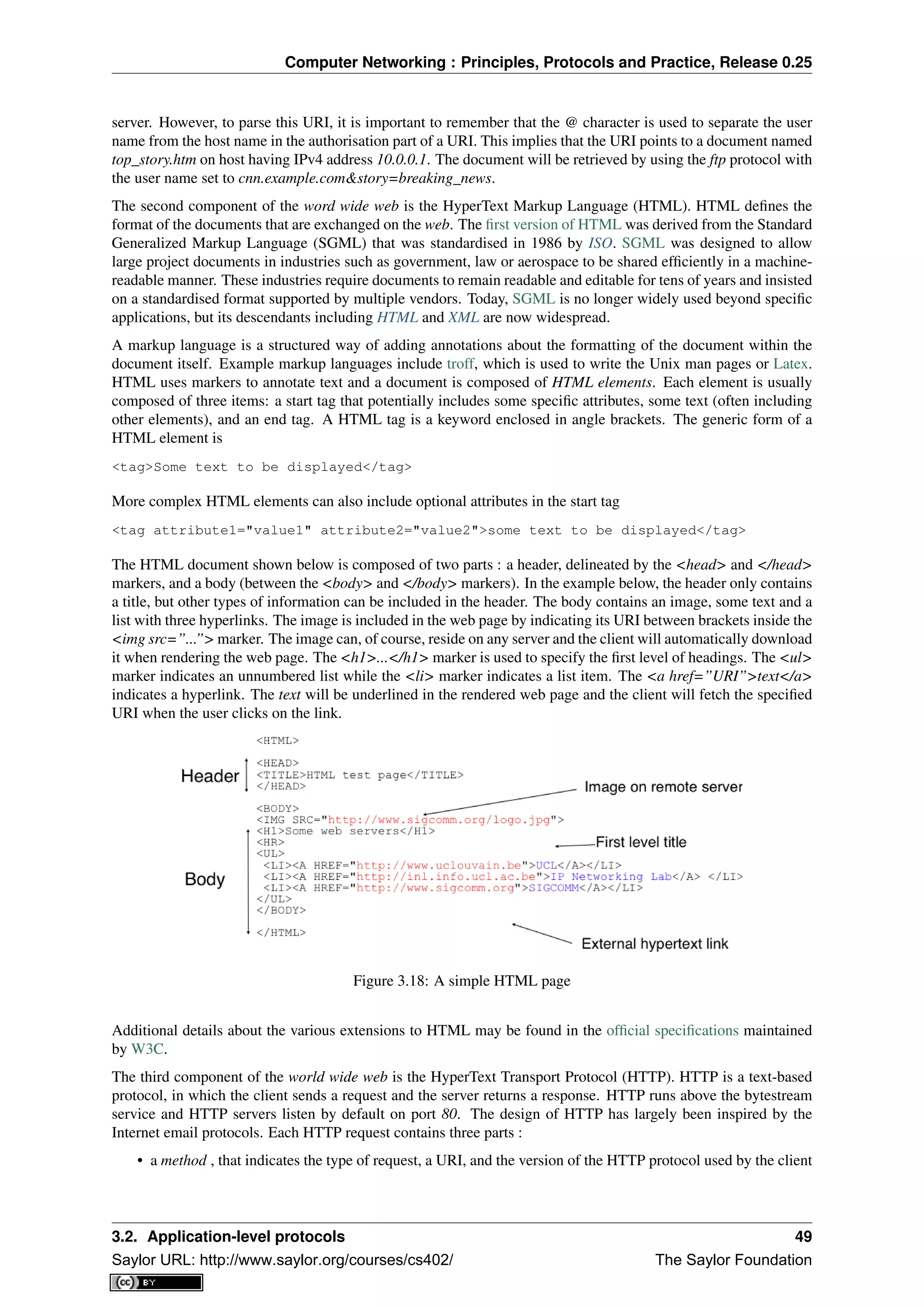
ends with a description of the key protocols of the world wide web.
All these applications rely on the transport layer that is explained in chapter The transport layer. This is a key
layer in today’s networks as it contains all the mechanisms necessary to provide a reliable delivery of data over an
unreliable network. We cover the transport layer by first developing a simple reliable transport layer protocol and
then explain the details of the TCP and UDP protocols used in TCP/IP networks.
After the transport layer, we analyse the network layer in chapter The network layer. This is also a very important
layer as it is responsible for the delivery of packets from any source to any destination through intermediate routers.
In the network layer, we describe the two possible organisations of the network layer and the routing protocols
based on link-state and distance vectors. Then we explain in detail the IPv4, IPv6, RIP, OSPF and BGP protocols
that are actually used in today’s Internet.
The last chapter of the book is devoted to the datalink layer. In chapter The datalink layer and the Local Area
Networks, we begin by explaining the principles of the datalink layers on point-to-point links. Then, we focus on
the Local Area Networks. We first describe the Medium Access Control algorithms that allow multiple hosts to
share one transmission medium. We consider both opportunistic and deterministic techniques. We then explain in
detail two types of LANs that are important from a deployment viewpoint today : Ethernet and WiFi.
7 A popular quote says, the devil is in the details. This quote reflects very well the operation of many network protocols, where the change
of a single bit may have huge consequences. In computer networks, understanding all the details is sometimes necessary.
2.3. Organisation of the book 25
Saylor URL: http://www.saylor.org/courses/cs402/ The Saylor Foundation](https://image.slidesharecdn.com/computer-networking-principles-bonaventure-1-30-31-otc1-150825141809-lva1-app6891/75/Computer-networking-principles-bonaventure-1-30-31-otc1-29-2048.jpg)
![Computer Networking : Principles, Protocols and Practice, Release 0.25
• @ : 1000000b
• space : 0100000b
In addition, the ASCII table also defines several non-printable or control characters. These characters were de-
signed to allow an application to control a printer or a terminal. These control characters include CR and LF, that
are used to terminate a line, and the Bell character which causes the terminal to emit a sound.
• carriage return (CR) : 0001101b
• line feed (LF) : 0001010b
• Bell: 0000111b
The ASCII characters are encoded as a seven bits field, but transmitted as an eight-bits byte whose high order bit
is usually set to 0. Bytes are always transmitted starting from the high order or most significant bit.
Most applications exchange strings that are composed of fixed or variable numbers of characters. A common
solution to define the character strings that are acceptable is to define them as a grammar using a Backus-Naur
Form (BNF) such as the Augmented BNF defined in RFC 5234. A BNF is a set of production rules that generate
all valid character strings. For example, consider a networked application that uses two commands, where the
user can supply a username and a password. The BNF for this application could be defined as shown in the figure
below.
Figure 3.2: A simple BNF specification
The example above defines several terminals and two commands : usercommand and passwordcommand. The
ALPHA terminal contains all letters in upper and lower case. In the ALPHA rule, %x41 corresponds to ASCII
character code 41 in hexadecimal, i.e. capital A. The CR and LF terminals correspond to the carriage return and
linefeed control characters. The CRLF rule concatenates these two terminals to match the standard end of line
termination. The DIGIT terminal contains all digits. The SP terminal corresponds to the white space characters.
The usercommand is composed of two strings separated by white space. In the ABNF rules that define the
messages used by Internet applications, the commands are case-insensitive. The rule “user” corresponds to all
possible cases of the letters that compose the word between brackets, e.g. user, uSeR, USER, usER, ... A username
contains at least one letter and up to 8 letters. User names are case-sensitive as they are not defined as a string
between brackets. The password rule indicates that a password starts with a letter and can contain any number of
letters or digits. The white space and the control characters cannot appear in a password defined by the above rule.
Besides character strings, some applications also need to exchange 16 bits and 32 bits fields such as integers. A
naive solution would have been to send the 16- or 32-bits field as it is encoded in the host’s memory. Unfortunately,
there are different methods to store 16- or 32-bits fields in memory. Some CPUs store the most significant byte
of a 16-bits field in the first address of the field while others store the least significant byte at this location. When
networked applications running on different CPUs exchange 16 bits fields, there are two possibilities to transfer
them over the transport service :
• send the most significant byte followed by the least significant byte
• send the least significant byte followed by the most significant byte
The first possibility was named big-endian in a note written by Cohen [Cohen1980] while the second was named
little-endian. Vendors of CPUs that used big-endian in memory insisted on using big-endian encoding in net-
worked applications while vendors of CPUs that used little-endian recommended the opposite. Several studies
were written on the relative merits of each type of encoding, but the discussion became almost a religious issue
[Cohen1980]. Eventually, the Internet chose the big-endian encoding, i.e. multi-byte fields are always transmit-
ted by sending the most significant byte first, RFC 791 refers to this encoding as the network-byte order. Most
3.1. Principles 29
Saylor URL: http://www.saylor.org/courses/cs402/ The Saylor Foundation](https://image.slidesharecdn.com/computer-networking-principles-bonaventure-1-30-31-otc1-150825141809-lva1-app6891/75/Computer-networking-principles-bonaventure-1-30-31-otc1-33-2048.jpg)
![Computer Networking : Principles, Protocols and Practice, Release 0.25
libraries 1
used to write networked applications contain functions to convert multi-byte fields from memory to the
network byte order and vice versa.
Besides 16 and 32 bit words, some applications need to exchange data structures containing bit fields of various
lengths. For example, a message may be composed of a 16 bits field followed by eight, one bit flags, a 24 bits
field and two 8 bits bytes. Internet protocol specifications will define such a message by using a representation
such as the one below. In this representation, each line corresponds to 32 bits and the vertical lines are used to
delineate fields. The numbers above the lines indicate the bit positions in the 32-bits word, with the high order bit
at position 0.
Figure 3.3: Message format
The message mentioned above will be transmitted starting from the upper 32-bits word in network byte order. The
first field is encoded in 16 bits. It is followed by eight one bit flags (A-H), a 24 bits field whose high order byte is
shown in the first line and the two low order bytes appear in the second line followed by two one byte fields. This
ASCII representation is frequently used when defining binary protocols. We will use it for all the binary protocols
that are discussed in this book.
We will discuss several examples of application-level protocols in this chapter.
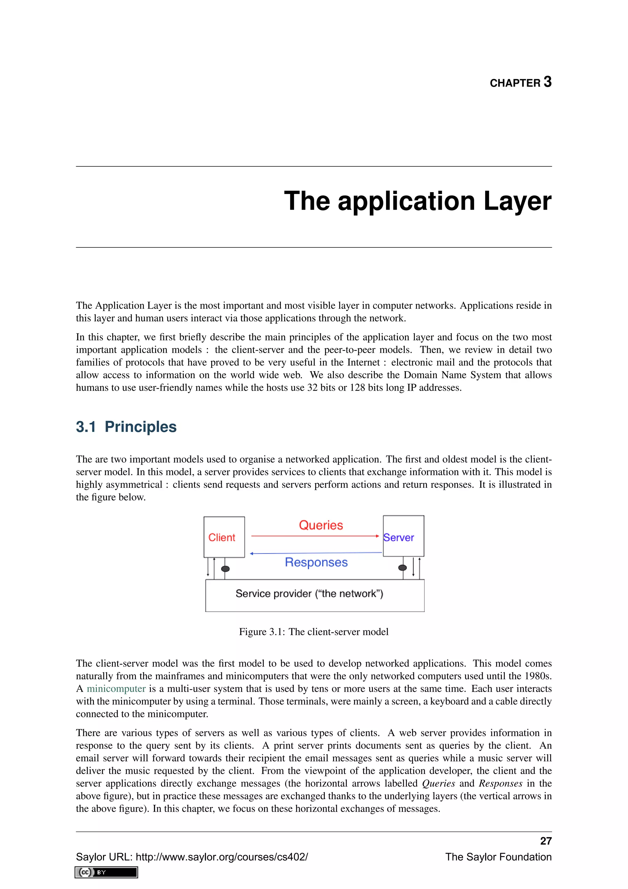
3.1.1 The peer-to-peer model
The peer-to-peer model emerged during the last ten years as another possible architecture for networked appli-
cations. In the traditional client-server model, hosts act either as servers or as clients and a server serves a large
number of clients. In the peer-to-peer model, all hosts act as both servers and clients and they play both roles.
The peer-to-peer model has been used to develop various networked applications, ranging from Internet telephony
to file sharing or Internet-wide filesystems. A detailed description of peer-to-peer applications may be found in
[BYL2008]. Surveys of peer-to-peer protocols and applications may be found in [AS2004] and [LCP2005].
3.1.2 The transport services
Networked applications are built on top of the transport service. As explained in the previous chapter, there are
two main types of transport services :
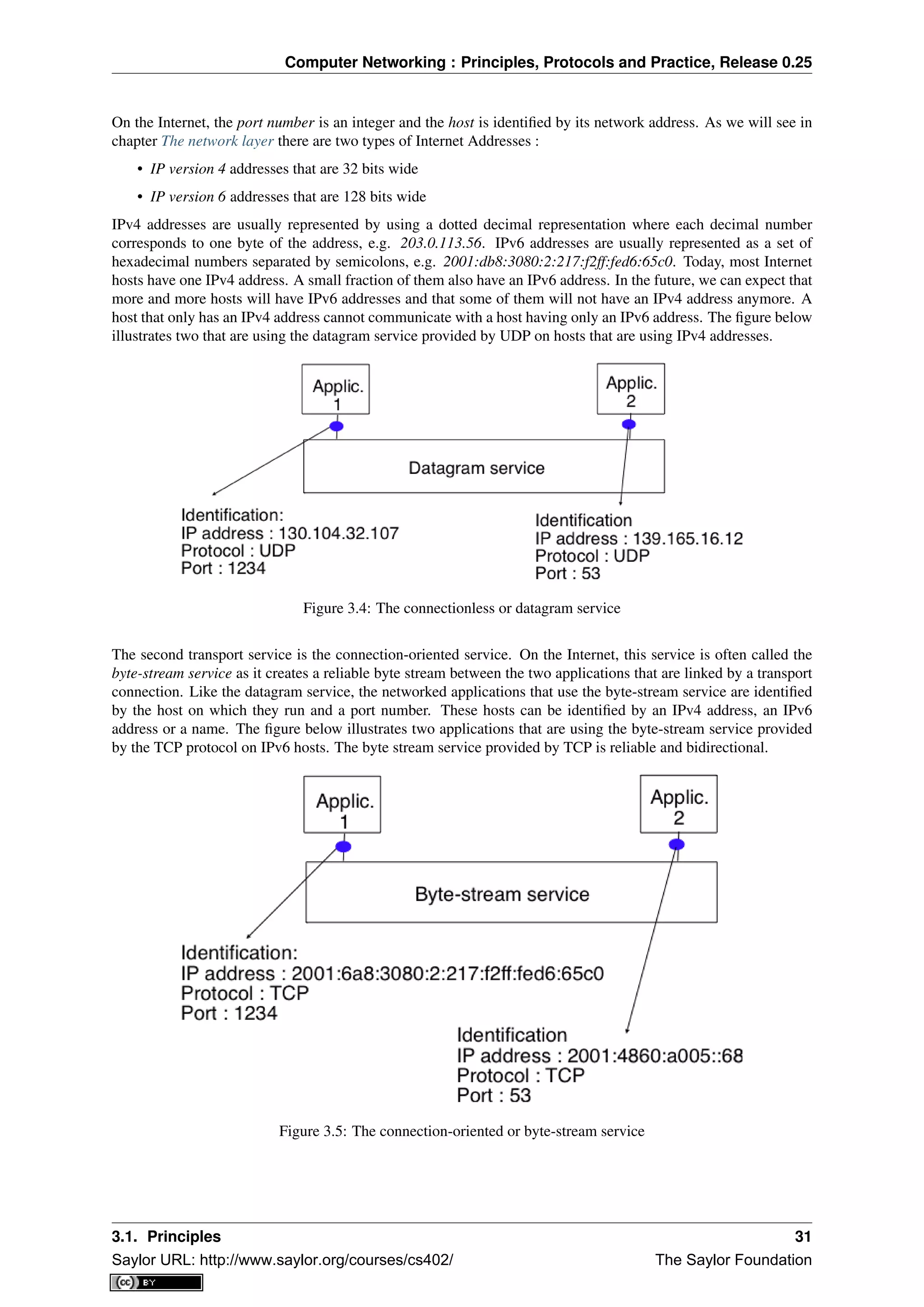
• the connectionless or datagram service
• the connection-oriented or byte-stream service
The connectionless service allows applications to easily exchange messages or Service Data Units. On the Internet,
this service is provided by the UDP protocol that will be explained in the next chapter. The connectionless transport
service on the Internet is unreliable, but is able to detect transmission errors. This implies that an application will
not receive an SDU that has been corrupted due to transmission errors.
The connectionless transport service allows networked application to exchange messages. Several networked
applications may be running at the same time on a single host. Each of these applications must be able to exchange
SDUs with remote applications. To enable these exchanges of SDUs, each networked application running on a
host is identified by the following information :
• the host on which the application is running
• the port number on which the application listens for SDUs
1 For example, the htonl(3) (resp. ntohl(3)) function the standard C library converts a 32-bits unsigned integer from the byte order
used by the CPU to the network byte order (resp. from the network byte order to the CPU byte order). Similar functions exist in other
programming languages.
30 Chapter 3. The application Layer
Saylor URL: http://www.saylor.org/courses/cs402/ The Saylor Foundation](https://image.slidesharecdn.com/computer-networking-principles-bonaventure-1-30-31-otc1-150825141809-lva1-app6891/75/Computer-networking-principles-bonaventure-1-30-31-otc1-34-2048.jpg)

![Computer Networking : Principles, Protocols and Practice, Release 0.25
A nameserver that is responsible for domain dom can directly answer the following queries :
• the IP address of any host residing directly inside domain dom (e.g. h2.dom in the figure above)
• the nameserver(s) that are responsible for any direct sub-domain of domain dom (i.e. sdom1.dom and
sdom2.dom in the figure above, but not z.sdom1.dom)
To retrieve the mapping for host h2.dom, a client sends its query to the name server that is responsible for domain
.dom. The name server directly answers the query. To retrieve a mapping for h3.a.sdom1.dom a DNS client first
sends a query to the name server that is responsible for the .dom domain. This nameserver returns the nameserver
that is responsible for the sdom1.dom domain. This nameserver can now be contacted to obtain the nameserver
that is responsible for the a.sdom1.dom domain. This nameserver can be contacted to retrieve the mapping for the
h3.a.sdom1.dom name. Thanks to this organisation of the nameservers, it is possible for a DNS client to obtain the
mapping of any host inside the .dom domain or any of its subdomains. To ensure that any DNS client will be able
to resolve any fully qualified domain name, there are special nameservers that are responsible for the root of the
domain name hierarchy. These nameservers are called root nameserver. There are currently about a dozen root
nameservers 6
.
Each root nameserver maintains the list 7
of all the nameservers that are responsible for each of the top-level
domain names and their IP addresses 8
. All root nameservers are synchronised and provide the same answers.
By querying any of the root nameservers, a DNS client can obtain the nameserver that is responsible for any
top-level-domain name. From this nameserver, it is possible to resolve any domain name.
To be able to contact the root nameservers, each DNS client must know their IP addresses. This implies, that
DNS clients must maintain an up-to-date list of the IP addresses of the root nameservers 9
. Without this list, it
is impossible to contact the root nameservers. Forcing all Internet hosts to maintain the most recent version of
this list would be difficult from an operational point of view. To solve this problem, the designers of the DNS
introduced a special type of DNS server : the DNS resolvers. A resolver is a server that provides the name
resolution service for a set of clients. A network usually contains a few resolvers. Each host in these networks is
configured to send all its DNS queries via one of its local resolvers. These queries are called recursive queries as
the resolver must recurse through the hierarchy of nameservers to obtain the answer.
DNS resolvers have several advantages over letting each Internet host query directly nameservers. Firstly, regular
Internet hosts do not need to maintain the up-to-date list of the IP addresses of the root servers. Secondly, regular
Internet hosts do not need to send queries to nameservers all over the Internet. Furthermore, as a DNS resolver
serves a large number of hosts, it can cache the received answers. This allows the resolver to quickly return
answers for popular DNS queries and reduces the load on all DNS servers [JSBM2002].
The last component of the Domain Name System is the DNS protocol. The DNS protocol runs above both the
datagram service and the bytestream services. In practice, the datagram service is used when short queries and
responses are exchanged, and the bytestream service is used when longer responses are expected. In this section,
we will only discuss the utilisation of the DNS protocol above the datagram service. This is the most frequent
utilisation of the DNS.
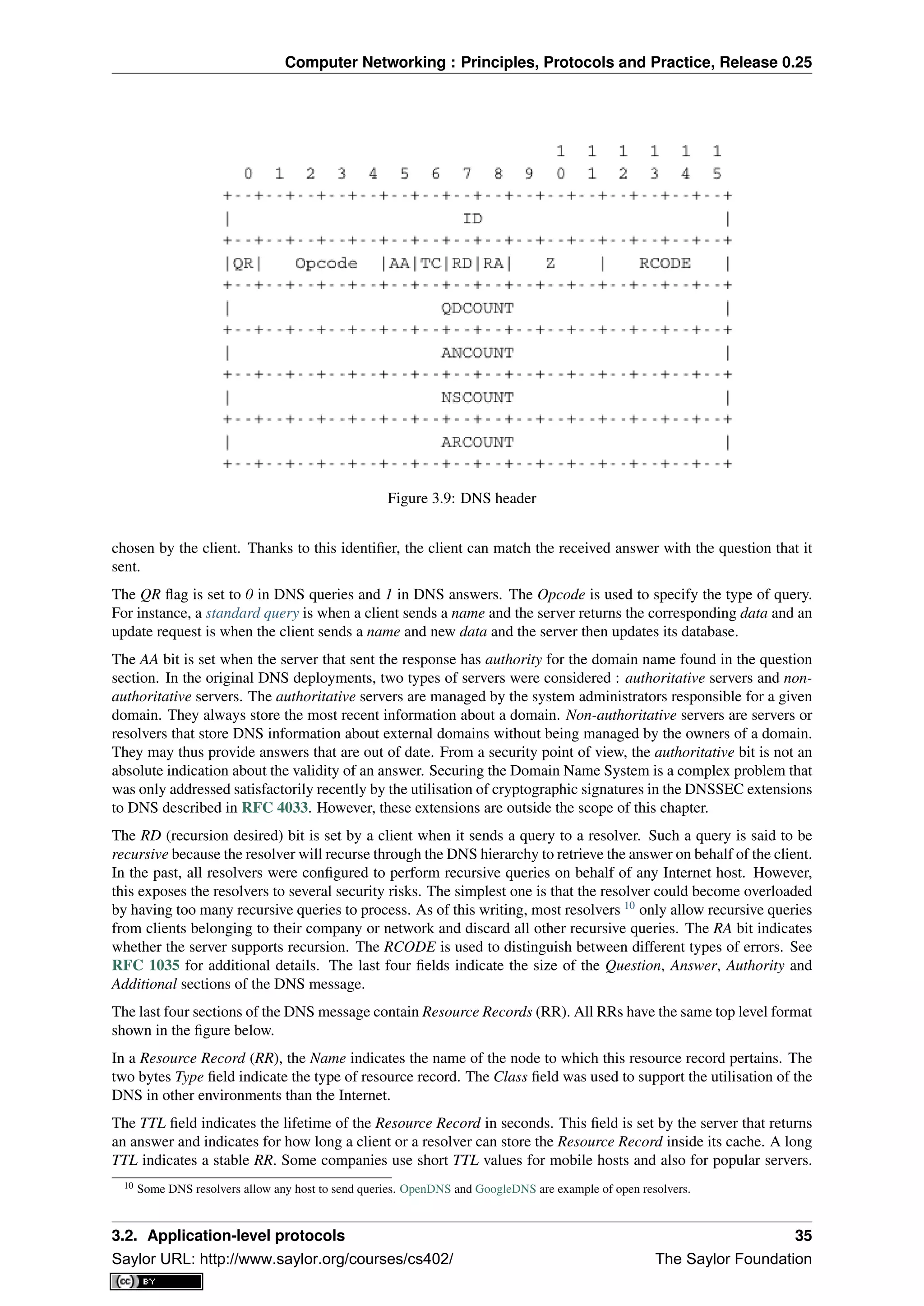
DNS messages are composed of five parts that are named sections in RFC 1035. The first three sections are
mandatory and the last two sections are optional. The first section of a DNS message is its Header. It contains
information about the type of message and the content of the other sections. The second section contains the
Question sent to the name server or resolver. The third section contains the Answer to the Question. When a client
sends a DNS query, the Answer section is empty. The fourth section, named Authority, contains information about
the servers that can provide an authoritative answer if required. The last section contains additional information
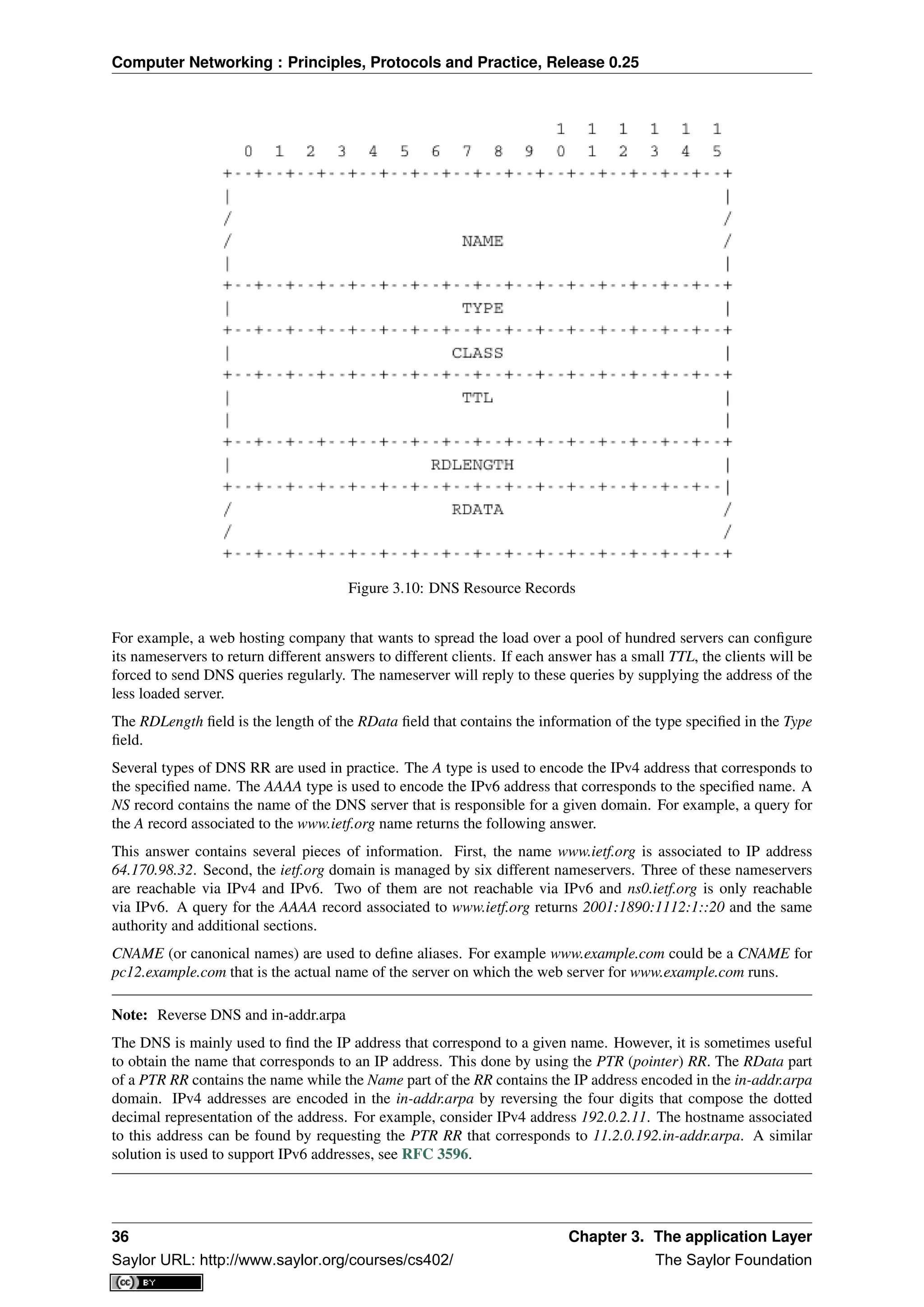
that is supplied by the resolver or server but was not requested in the question.
The header of DNS messages is composed of 12 bytes and its structure is shown in the figure below.
The ID (identifier) is a 16-bits random value chosen by the client. When a client sends a question to a DNS server,
it remembers the question and its identifier. When a server returns an answer, it returns in the ID field the identifier
6 There are currently 13 root servers. In practice, some of these root servers are themselves implemented as a set of distinct physical
servers. See http://www.root-servers.org/ for more information about the physical location of these servers.
7 A copy of the information maintained by each root nameserver is available at http://www.internic.net/zones/root.zone
8 Until February 2008, the root DNS servers only had IPv4 addresses. IPv6 addresses were added to the root DNS servers slowly to
avoid creating problems as discussed in http://www.icann.org/en/committees/security/sac018.pdf In 2010, several DNS root servers are still
not reachable by using IPv6.
9 The current list of the IP addresses of the root nameservers is maintained at http://www.internic.net/zones/named.root . These IP addresses
are stable and root nameservers seldom change their IP addresses. DNS resolvers must however maintain an up-to-date copy of this file.
34 Chapter 3. The application Layer
Saylor URL: http://www.saylor.org/courses/cs402/ The Saylor Foundation](https://image.slidesharecdn.com/computer-networking-principles-bonaventure-1-30-31-otc1-150825141809-lva1-app6891/75/Computer-networking-principles-bonaventure-1-30-31-otc1-38-2048.jpg)
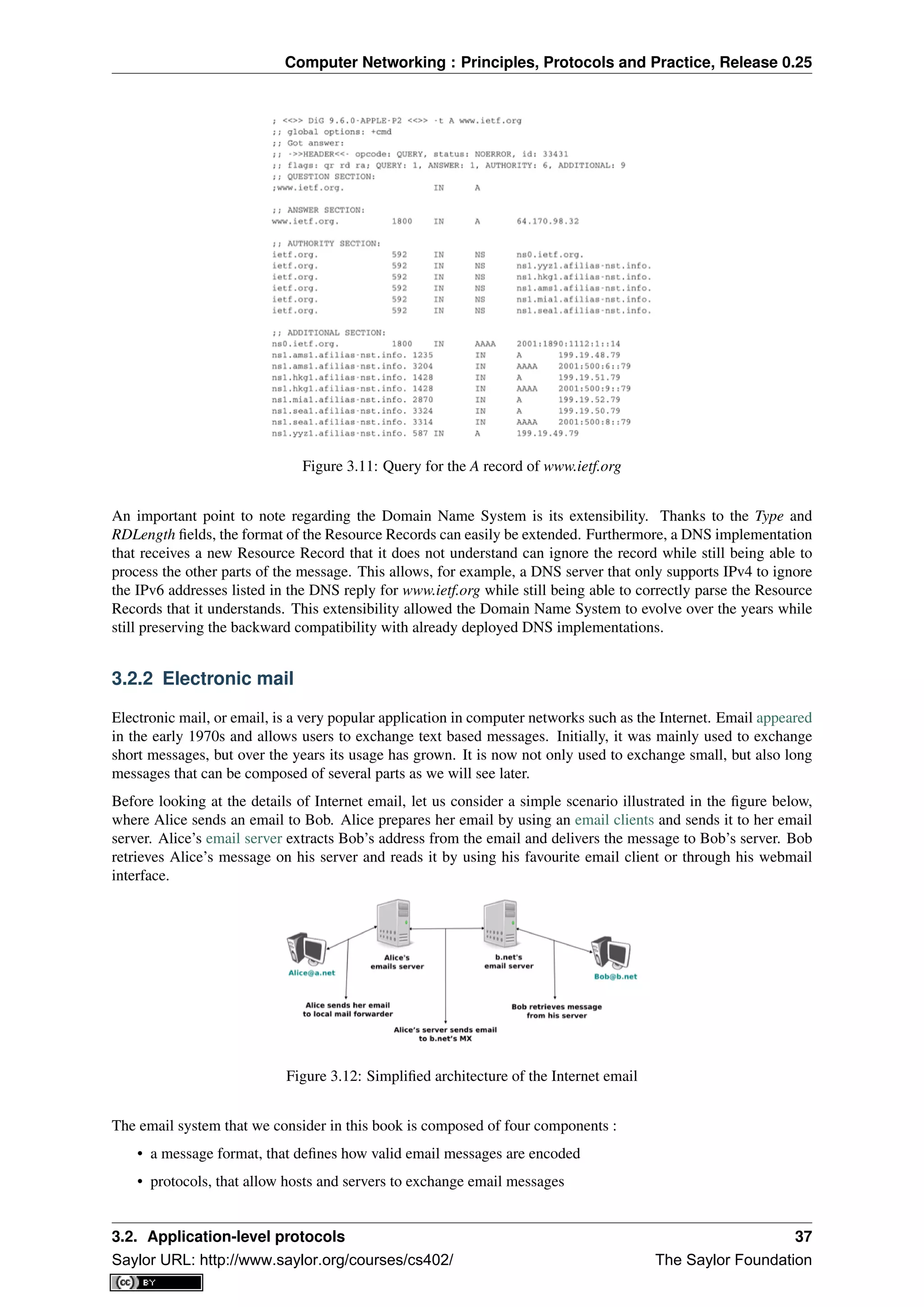
![Computer Networking : Principles, Protocols and Practice, Release 0.25
• client software, that allows users to easily create and read email messages
• software, that allows servers to efficiently exchange email messages
We will first discuss the format of email messages followed by the protocols that are used on today’s Internet to
exchange and retrieve emails. Other email systems have been developed in the past [Bush1993] [Genilloud1990]
[GC2000], but today most email solutions have migrated to the Internet email. Information about the software
that is used to compose and deliver emails may be found on wikipedia among others, for both email clients and
email servers. More detailed information about the full Internet Mail Architecture may be found in RFC 5598.
Email messages, like postal mail, are composed of two parts :
• a header that plays the same role as the letterhead in regular mail. It contains metadata about the message.
• the body that contains the message itself.
Email messages are entirely composed of lines of ASCII characters. Each line can contain up to 998 characters
and is terminated by the CR and LF control characters RFC 5322. The lines that compose the header appear
before the message body. An empty line, containing only the CR and LF characters, marks the end of the header.
This is illustrated in the figure below.
Figure 3.13: The structure of email messages
The email header contains several lines that all begin with a keyword followed by a colon and additional informa-
tion. The format of email messages and the different types of header lines are defined in RFC 5322. Two of these
header lines are mandatory and must appear in all email messages :
• The sender address. This header line starts with From:. This contains the (optional) name of the sender
followed by its email address between < and >. Email addresses are always composed of a username
followed by the @ sign and a domain name.
• The date. This header line starts with Date:. RFC 5322 precisely defines the format used to encode a date.
Other header lines appear in most email messages. The Subject: header line allows the sender to indicate the topic
discussed in the email. Three types of header lines can be used to specify the recipients of a message :
• the To: header line contains the email addresses of the primary recipients of the message 11
. Several
addresses can be separated by using commas.
• the cc: header line is used by the sender to provide a list of email addresses that must receive a carbon copy
of the message. Several addresses can be listed in this header line, separated by commas. All recipients of
the email message receive the To: and cc: header lines.
• the bcc: header line is used by the sender to provide a list of comma separated email addresses that must
receive a blind carbon copy of the message. The bcc: header line is not delivered to the recipients of the
email message.
A simple email message containing the From:, To:, Subject: and Date: header lines and two lines of body is shown
below.
11 It could be surprising that the To: is not mandatory inside an email message. While most email messages will contain this header line an
email that does not contain a To: header line and that relies on the bcc: to specify the recipient is valid as well.
38 Chapter 3. The application Layer
Saylor URL: http://www.saylor.org/courses/cs402/ The Saylor Foundation](https://image.slidesharecdn.com/computer-networking-principles-bonaventure-1-30-31-otc1-150825141809-lva1-app6891/75/Computer-networking-principles-bonaventure-1-30-31-otc1-42-2048.jpg)
![Computer Networking : Principles, Protocols and Practice, Release 0.25
From: Bob Smith <Bob@machine.example>
To: Alice Doe <alice@example.net>, Alice Smith <Alice@machine.example>
Subject: Hello
Date: Mon, 8 Mar 2010 19:55:06 -0600
This is the "Hello world" of email messages.
This is the second line of the body
Note the empty line after the Date: header line; this empty line contains only the CR and LF characters, and marks
the boundary between the header and the body of the message.
Several other optional header lines are defined in RFC 5322 and elsewhere 12
. Furthermore, many email clients
and servers define their own header lines starting from X-. Several of the optional header lines defined in RFC
5322 are worth being discussed here :
• the Message-Id: header line is used to associate a “unique” identifier to each email. Email identifiers are
usually structured like string@domain where string is a unique character string or sequence number chosen
by the sender of the email and domain the domain name of the sender. Since domain names are unique,
a host can generate globally unique message identifiers concatenating a locally unique identifier with its
domain name.
• the In-reply-to: is used when a message was created in reply to a previous message. In this case, the end of
the In-reply-to: line contains the identifier of the original message.
• the Received: header line is used when an email message is processed by several servers before reaching its
destination. Each intermediate email server adds a Received: header line. These header lines are useful to
debug problems in delivering email messages.
The figure below shows the header lines of one email message. The message originated at a host named
wira.firstpr.com.au and was received by smtp3.sgsi.ucl.ac.be. The Received: lines have been wrapped for read-
ability.
Received: from smtp3.sgsi.ucl.ac.be (Unknown [10.1.5.3])
by mmp.sipr-dc.ucl.ac.be
(Sun Java(tm) System Messaging Server 7u3-15.01 64bit (built Feb 12 2010))
with ESMTP id <0KYY00L85LI5JLE0@mmp.sipr-dc.ucl.ac.be>; Mon,
08 Mar 2010 11:37:17 +0100 (CET)
Received: from mail.ietf.org (mail.ietf.org [64.170.98.32])
by smtp3.sgsi.ucl.ac.be (Postfix) with ESMTP id B92351C60D7; Mon,
08 Mar 2010 11:36:51 +0100 (CET)
Received: from [127.0.0.1] (localhost [127.0.0.1]) by core3.amsl.com (Postfix)
with ESMTP id F066A3A68B9; Mon, 08 Mar 2010 02:36:38 -0800 (PST)
Received: from localhost (localhost [127.0.0.1]) by core3.amsl.com (Postfix)
with ESMTP id A1E6C3A681B for <rrg@core3.amsl.com>; Mon,
08 Mar 2010 02:36:37 -0800 (PST)
Received: from mail.ietf.org ([64.170.98.32])
by localhost (core3.amsl.com [127.0.0.1]) (amavisd-new, port 10024)
with ESMTP id erw8ih2v8VQa for <rrg@core3.amsl.com>; Mon,
08 Mar 2010 02:36:36 -0800 (PST)
Received: from gair.firstpr.com.au (gair.firstpr.com.au [150.101.162.123])
by core3.amsl.com (Postfix) with ESMTP id 03E893A67ED for <rrg@irtf.org>; Mon,
08 Mar 2010 02:36:35 -0800 (PST)
Received: from [10.0.0.6] (wira.firstpr.com.au [10.0.0.6])
by gair.firstpr.com.au (Postfix) with ESMTP id D0A49175B63; Mon,
08 Mar 2010 21:36:37 +1100 (EST)
Date: Mon, 08 Mar 2010 21:36:38 +1100
From: Robin Whittle <rw@firstpr.com.au>
Subject: Re: [rrg] Recommendation and what happens next
In-reply-to: <C7B9C21A.4FAB%tony.li@tony.li>
To: RRG <rrg@irtf.org>
Message-id: <4B94D336.7030504@firstpr.com.au>
12 The list of all standard email header lines may be found at http://www.iana.org/assignments/message-headers/message-header-index.html
3.2. Application-level protocols 39
Saylor URL: http://www.saylor.org/courses/cs402/ The Saylor Foundation](https://image.slidesharecdn.com/computer-networking-principles-bonaventure-1-30-31-otc1-150825141809-lva1-app6891/75/Computer-networking-principles-bonaventure-1-30-31-otc1-43-2048.jpg)
![Computer Networking : Principles, Protocols and Practice, Release 0.25
First part
--simple boundary
Content-Type: text/plain; charset=us-ascii
Second part
--simple boundary
The Content-Type: header can also be used inside a MIME part. In this case, it indicates the type of data placed
in this part. Each data type is specified as a type followed by a subtype. A detailed description may be found in
RFC 2046. Some of the most popular Content-Type: header lines are :
• text. The message part contains information in textual format. There are several subtypes : text/plain for
regular ASCII text, text/html defined in RFC 2854 for documents in HTML format or the text/enriched
format defined in RFC 1896. The Content-Type: header line may contain a second parameter that specifies
the character set used to encode the text. charset=us-ascii is the standard ASCII character table. Other
frequent character sets include charset=UTF8 or charset=iso-8859-1. The list of standard character sets is
maintained by IANA
• image. The message part contains a binary representation of an image. The subtype indicates the format of
the image such as gif, jpg or png.
• audio. The message part contains an audio clip. The subtype indicates the format of the audio clip like wav
or mp3
• video. The message part contains a video clip. The subtype indicates the format of the video clip like avi or
mp4
• application. The message part contains binary information that was produced by the particular application
listed as the subtype. Email clients use the subtype to launch the application that is able to decode the
received binary information.
Note: From ASCII to Unicode
The first computers used different techniques to represent characters in memory and on disk. During the 1960s,
computers began to exchange information via tape or telephone lines. Unfortunately, each vendor had its own
proprietary character set and exchanging data between computers from different vendors was often difficult. The
7 bits ASCII character table RFC 20 set was adopted by several vendors and by many Internet protocols. However,
ASCII became a problem with the internationalisation of the Internet and the desire of more and more users to use
character sets that support their own written language. A first attempt at solving this problem was the definition
of the ISO-8859 character sets by ISO. This family of standards specified various character sets that allowed the
representation of many European written languages by using 8 bits characters. Unfortunately, an 8-bits character
set is not sufficient to support some widely used languages, such as those used in Asian countries. Fortunately, at
the end of the 1980s, several computer scientists proposed to develop a standard that supports all written languages
used on Earth today. The Unicode standard [Unicode] has now been adopted by most computer and software
vendors. For example, Java uses Unicode natively to manipulate characters, Python can handle both ASCII and
Unicode characters. Internet applications are slowly moving towards complete support for the Unicode character
sets, but moving from ASCII to Unicode is an important change that can have a huge impact on current deployed
implementations. See for example, the work to completely internationalise email RFC 4952 and domain names
RFC 5890.
The last MIME header line is Content-Transfer-Encoding:. This header line is used after the Content-Type: header
line, within a message part, and specifies how the message part has been encoded. The default encoding is to use
7 bits ASCII. The most frequent encodings are quoted-printable and Base64. Both support encoding a sequence
of bytes into a set of ASCII lines that can be safely transmitted by email servers. quoted-printable is defined in
RFC 2045. We briefly describe base64 which is defined in RFC 2045 and RFC 4648.
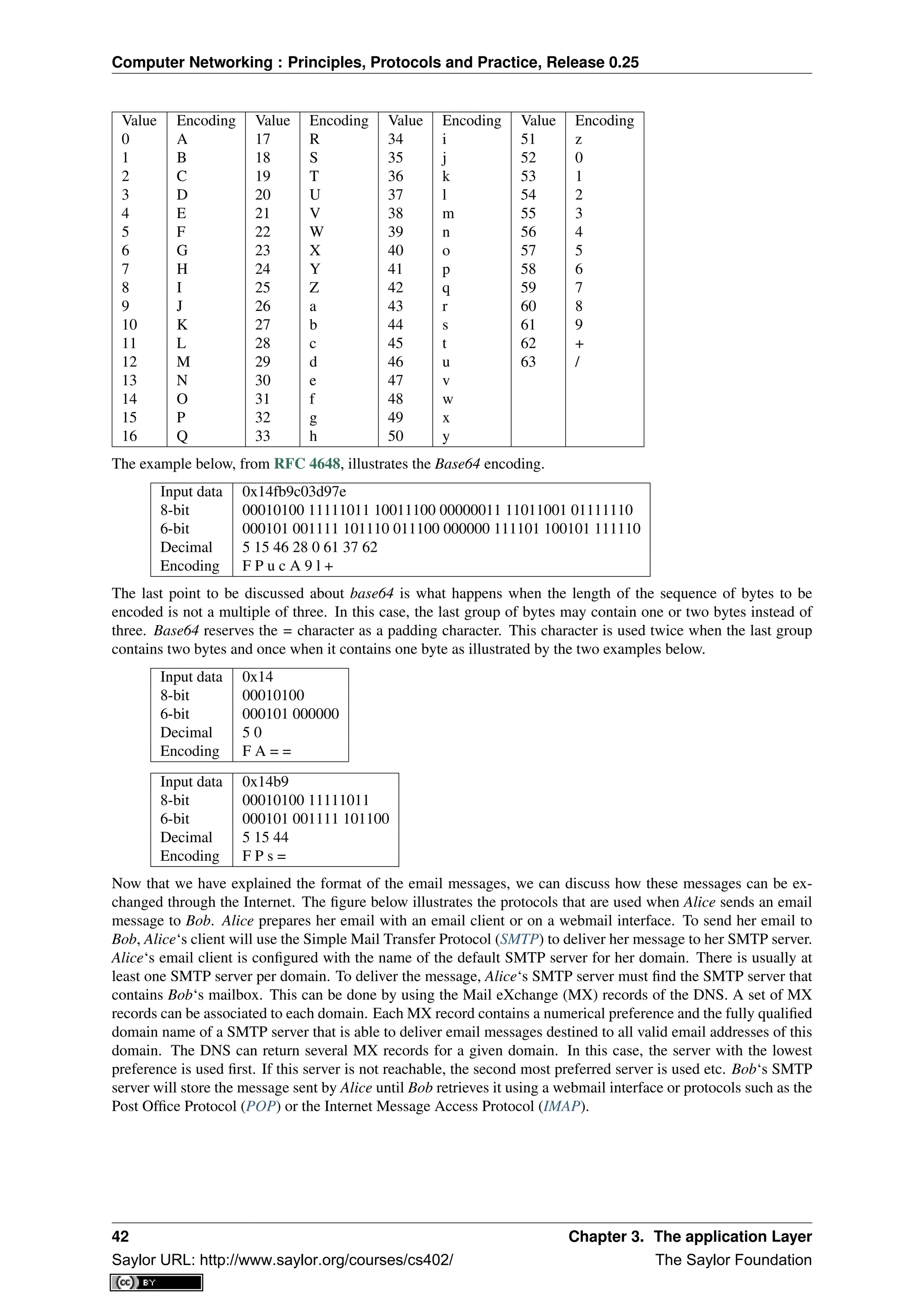
Base64 divides the sequence of bytes to be encoded into groups of three bytes (with the last group possibly being
partially filled). Each group of three bytes is then divided into four six-bit fields and each six bit field is encoded
as a character from the table below.
3.2. Application-level protocols 41
Saylor URL: http://www.saylor.org/courses/cs402/ The Saylor Foundation](https://image.slidesharecdn.com/computer-networking-principles-bonaventure-1-30-31-otc1-150825141809-lva1-app6891/75/Computer-networking-principles-bonaventure-1-30-31-otc1-45-2048.jpg)

![Computer Networking : Principles, Protocols and Practice, Release 0.25
Many FTP clients offer a user interface similar to a Unix shell and allow the client to browse the file system on
the server and to send and retrieve files. FTP servers can be configured in two modes :
• authenticated : in this mode, the ftp server only accepts users with a valid user name and password. Once
authenticated, they can access the files and directories according to their permissions
• anonymous : in this mode, clients supply the anonymous userid and their email address as password. These
clients are granted access to a special zone of the file system that only contains public files.
ftp was very popular in the 1990s and early 2000s, but today it has mostly been superseded by more recent
protocols. Authenticated access to files is mainly done by using the Secure Shell (ssh) protocol defined in RFC
4251 and supported by clients such as scp or sftp. Nowadays, anonymous access is mainly provided by web
protocols.
In the late 1980s, high energy physicists working at CERN had to efficiently exchange documents about their
ongoing and planned experiments. Tim Berners-Lee evaluated several of the documents sharing techniques that
were available at that time [B1989]. As none of the existing solutions met CERN’s requirements, they choose to
develop a completely new document sharing system. This system was initially called the mesh, but was quickly
renamed the world wide web. The starting point for the world wide web are hypertext documents. An hypertext
document is a document that contains references (hyperlinks) to other documents that the reader can immediately
access. Hypertext was not invented for the world wide web. The idea of hypertext documents was proposed in
1945 [Bush1945] and the first experiments were done during the 1960s [Nelson1965] [Myers1998] . Compared to
the hypertext documents that were used in the late 1980s, the main innovation introduced by the world wide web
was to allow hyperlinks to reference documents stored on remote machines.
Figure 3.17: World-wide web clients and servers
A document sharing system such as the world wide web is composed of three important parts.
1. A standardised addressing scheme that allows unambiguous identification of documents
2. A standard document format : the HyperText Markup Language
3. A standardised protocol that facilitates efficient retrieval of documents stored on a server
Note: Open standards and open implementations
Open standards have, and are still playing a key role in the success of the world wide web as we know it to-
day. Without open standards, the world wide web would never have reached its current size. In addition to open
standards, another important factor for the success of the web was the availability of open and efficient imple-
mentations of these standards. When CERN started to work on the web, their objective was to build a running
system that could be used by physicists. They developed open-source implementations of the first web servers and
web clients. These open-source implementations were powerful and could be used as is, by institutions willing to
3.2. Application-level protocols 47
Saylor URL: http://www.saylor.org/courses/cs402/ The Saylor Foundation](https://image.slidesharecdn.com/computer-networking-principles-bonaventure-1-30-31-otc1-150825141809-lva1-app6891/75/Computer-networking-principles-bonaventure-1-30-31-otc1-51-2048.jpg)
![Computer Networking : Principles, Protocols and Practice, Release 0.25
share information on the web. They were also extended by other developers who contributed to new features. For
example, NCSA added support for images in their Mosaic browser that was eventually used to create Netscape
Communications.
The first components of the world wide web are the Uniform Resource Identifiers (URI), defined in RFC 3986. A
URI is a character string that unambiguously identifies a resource on the world wide web. Here is a subset of the
BNF for URIs
URI = scheme ":" "//" authority path [ "?" query ] [ "#" fragment ]
scheme = ALPHA *( ALPHA / DIGIT / "+" / "-" / "." )
authority = [ userinfo "@" ] host [ ":" port ]
query = *( pchar / "/" / "?" )
fragment = *( pchar / "/" / "?" )
pchar = unreserved / pct-encoded / sub-delims / ":" / "@"
query = *( pchar / "/" / "?" )
fragment = *( pchar / "/" / "?" )
pct-encoded = "%" HEXDIG HEXDIG
unreserved = ALPHA / DIGIT / "-" / "." / "_" / "~"
reserved = gen-delims / sub-delims
gen-delims = ":" / "/" / "?" / "#" / "[" / "]" / "@"
sub-delims = "!" / "$" / "&" / "’" / "(" / ")" / "*" / "+" / "," / ";" / "="
The first component of a URI is its scheme. A scheme can be seen as a selector, indicating the meaning of the
fields after it. In practice, the scheme often identifies the application-layer protocol that must be used by the client
to retrieve the document, but it is not always the case. Some schemes do not imply a protocol at all and some
do not indicate a retrievable document 17
. The most frequent scheme is http that will be described later. A URI
scheme can be defined for almost any application layer protocol [#furilist]_. The characters ‘: and // follow the
scheme of any URI.
The second part of the URI is the authority. With retrievable URI, this includes the DNS name or the IP address
of the server where the document can be retrieved using the protocol specified via the scheme. This name can
be preceded by some information about the user (e.g. a user name) who is requesting the information. Earlier
definitions of the URI allowed the specification of a user name and a password before the @ character ( RFC
1738), but this is now deprecated as placing a password inside a URI is insecure. The host name can be followed
by the semicolon character and a port number. A default port number is defined for some protocols and the port
number should only be included in the URI if a non-default port number is used (for other protocols, techniques
like service DNS records are used).
The third part of the URI is the path to the document. This path is structured as filenames on a Unix host (but
it does not imply that the files are indeed stored this way on the server). If the path is not specified, the server
will return a default document. The last two optional parts of the URI are used to provide a query and indicate a
specific part (e.g. a section in an article) of the requested document. Sample URIs are shown below.
http://tools.ietf.org/html/rfc3986.html
mailto:infobot@example.com?subject=current-issue
http://docs.python.org/library/basehttpserver.html?highlight=http#BaseHTTPServer.BaseHTTPRequestHa
telnet://[2001:6a8:3080:3::2]:80/
ftp://cnn.example.com&story=breaking_news@10.0.0.1/top_story.htm
The first URI corresponds to a document named rfc3986.html that is stored on the server named tools.ietf.org and
can be accessed by using the http protocol on its default port. The second URI corresponds to an email message,
with subject current-issue, that will be sent to user infobot in domain example.com. The mailto: URI scheme is
defined in RFC 6068. The third URI references the portion BaseHTTPServer.BaseHTTPRequestHandler of the
document basehttpserver.html that is stored in the library directory on server docs.python.org. This document can
be retrieved by using the http protocol. The query highlight=http is associated to this URI. The fourth example is a
server that operates the telnet protocol, uses IPv6 address 2001:6a8:3080:3::2 and is reachable on port 80. The last
URI is somewhat special. Most users will assume that it corresponds to a document stored on the cnn.example.com
17 An example of a non-retrievable URI is urn:isbn:0-380-81593-1 which is an unique identifier for a book, through the urn scheme
(see RFC 3187). Of course, any URI can be make retrievable via a dedicated server or a new protocol but this one has no explicit proto-
col. Same thing for the scheme tag (see RFC 4151), often used in Web syndication (see RFC 4287 about the Atom syndication format).
Even when the scheme is retrievable (for instance with http‘), it is often used only as an identifier, not as a way to get a resource. See
http://norman.walsh.name/2006/07/25/namesAndAddresses for a good explanation.
48 Chapter 3. The application Layer
Saylor URL: http://www.saylor.org/courses/cs402/ The Saylor Foundation](https://image.slidesharecdn.com/computer-networking-principles-bonaventure-1-30-31-otc1-150825141809-lva1-app6891/75/Computer-networking-principles-bonaventure-1-30-31-otc1-52-2048.jpg)
![Computer Networking : Principles, Protocols and Practice, Release 0.25
• All status codes starting with digit 5 indicate an error on the server. 500 Internal Server Error indicates that
the server could not process the request due to an error on the server itself.
In both the HTTP request and the HTTP response, the MIME document refers to a representation of the document
with the MIME headers indicating the type of document and its size.
As an illustration of HTTP/1.0, the transcript below shows a HTTP request for http://www.ietf.org and the corre-
sponding HTTP response. The HTTP request was sent using the curl command line tool. The User-Agent: header
line contains more information about this client software. There is no MIME document attached to this HTTP
request, and it ends with a blank line.
GET / HTTP/1.0
User-Agent: curl/7.19.4 (universal-apple-darwin10.0) libcurl/7.19.4 OpenSSL/0.9.8l zlib/1.2.3
Host: www.ietf.org
The HTTP response indicates the version of the server software used with the modules included. The Last-
Modified: header indicates that the requested document was modified about one week before the request. A
HTML document (not shown) is attached to the response. Note the blank line between the header of the HTTP
response and the attached MIME document. The Server: header line has been truncated in this output.
HTTP/1.1 200 OK
Date: Mon, 15 Mar 2010 13:40:38 GMT
Server: Apache/2.2.4 (Linux/SUSE) mod_ssl/2.2.4 OpenSSL/0.9.8e (truncated)
Last-Modified: Tue, 09 Mar 2010 21:26:53 GMT
Content-Length: 17019
Content-Type: text/html
<!DOCTYPE HTML PUBLIC .../HTML>
HTTP was initially designed to share self-contained text documents. For this reason, and to ease the implemen-
tation of clients and servers, the designers of HTTP chose to open a TCP connection for each HTTP request.
This implies that a client must open one TCP connection for each URI that it wants to retrieve from a server as
illustrated on the figure below. For a web page containing only text documents this was a reasonable design choice
as the client usually remains idle while the (human) user is reading the retrieved document.
Figure 3.20: HTTP 1.0 and the underlying TCP connection
However, as the web evolved to support richer documents containing images, opening a TCP connection for each
URI became a performance problem [Mogul1995]. Indeed, besides its HTML part, a web page may include
dozens of images or more. Forcing the client to open a TCP connection for each component of a web page
has two important drawbacks. First, the client and the server must exchange packets to open and close a TCP
connection as we will see later. This increases the network overhead and the total delay of completely retrieving
all the components of a web page. Second, a large number of established TCP connections may be a performance
bottleneck on servers.
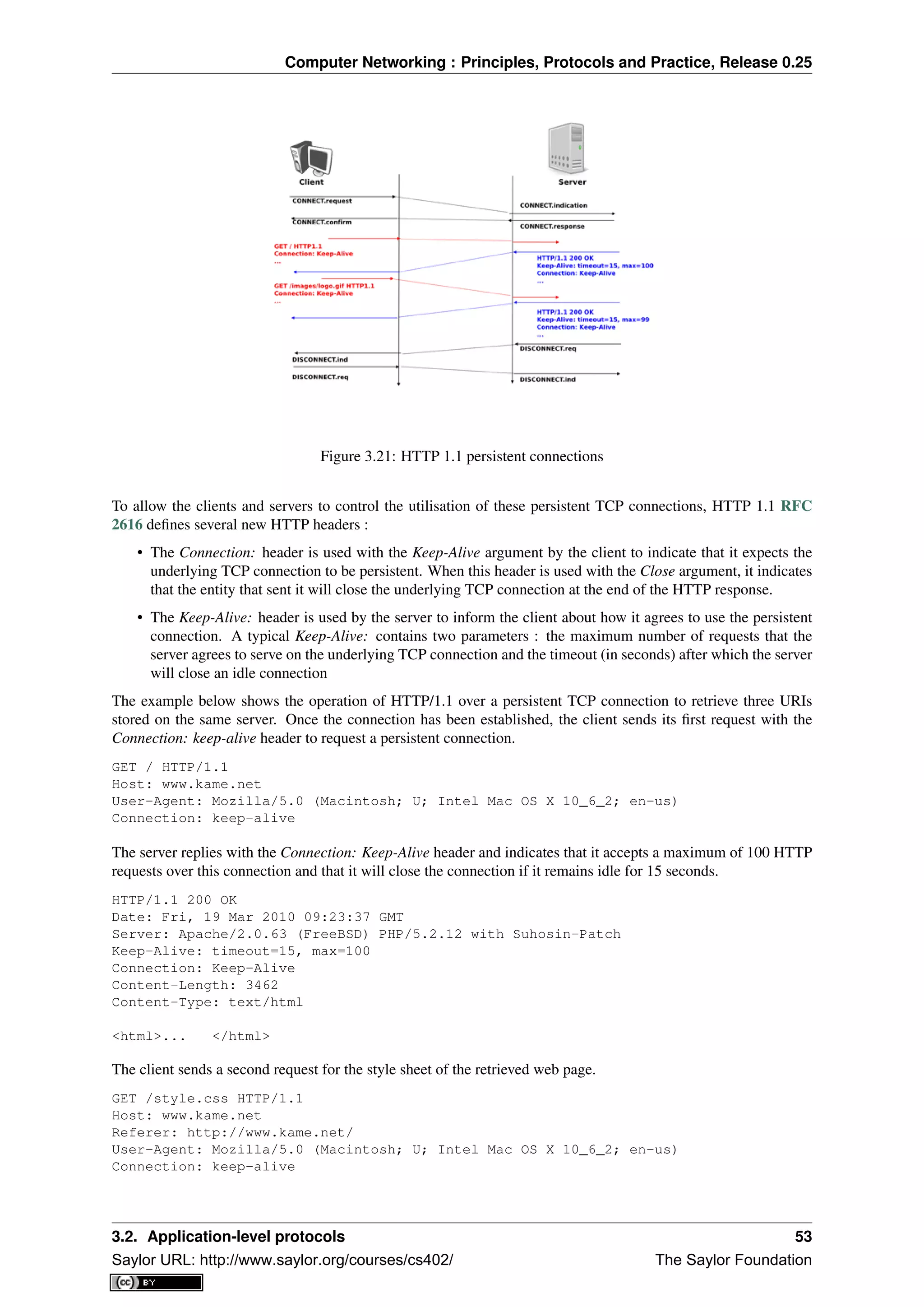
This problem was solved by extending HTTP to support persistent TCP connections RFC 2616. A persistent
connection is a TCP connection over which a client may send several HTTP requests. This is illustrated in the
figure below.
52 Chapter 3. The application Layer
Saylor URL: http://www.saylor.org/courses/cs402/ The Saylor Foundation](https://image.slidesharecdn.com/computer-networking-principles-bonaventure-1-30-31-otc1-150825141809-lva1-app6891/75/Computer-networking-principles-bonaventure-1-30-31-otc1-56-2048.jpg)
![Computer Networking : Principles, Protocols and Practice, Release 0.25
indicate its preferred languages. Unfortunately, in practice this header is usually set based on the default language
of the browser and it is not possible for a user to indicate the language it prefers to use by selecting options on
each visited web server.
The third, and widely adopted, solution are HTTP cookies. HTTP cookies were initially developed as a private
extension by Netscape. They are now part of the standard RFC 6265. In a nutshell, a cookie is a short string that
is chosen by a server to represent a given client. Two HTTP headers are used : Cookie: and Set-Cookie:. When a
server receives an HTTP request from a new client (i.e. an HTTP request that does not contain the Cookie: header),
it generates a cookie for the client and includes it in the Set-Cookie: header of the returned HTTP response. The
Set-Cookie: header contains several additional parameters including the domain names for which the cookie is
valid. The client stores all received cookies on disk and every time it sends a HTTP request, it verifies whether
it already knows a cookie for this domain. If so, it attaches the Cookie: header to the HTTP request. This is
illustrated in the figure below with HTTP 1.1, but cookies also work with HTTP 1.0.
Figure 3.22: HTTP cookies
Note: Privacy issues with HTTP cookies
The HTTP cookies introduced by Netscape are key for large e-commerce websites. However, they have also
raised many discussions concerning their potential misuses. Consider ad.com, a company that delivers lots of
advertisements on web sites. A web site that wishes to include ad.com‘s advertisements next to its content will
add links to ad.com inside its HTML pages. If ad.com is used by many web sites, ad.com could be able to track the
interests of all the users that visit its client websites and use this information to provide targeted advertisements.
Privacy advocates have even sued online advertisement companies to force them to comply with the privacy
regulations. More recent related technologies also raise privacy concerns
3.3 Writing simple networked applications
Networked applications were usually implemented by using the socket API. This API was designed when TCP/IP
was first implemented in the Unix BSD operating system [Sechrest] [LFJLMT], and has served as the model for
many APIs between applications and the networking stack in an operating system. Although the socket API is
very popular, other APIs have also been developed. For example, the STREAMS API has been added to several
Unix System V variants [Rago1993]. The socket API is supported by most programming languages and several
textbooks have been devoted to it. Users of the C language can consult [DC2009], [Stevens1998], [SFR2004] or
[Kerrisk2010]. The Java implementation of the socket API is described in [CD2008] and in the Java tutorial. In
this section, we will use the python implementation of the socket API to illustrate the key concepts. Additional
information about this API may be found in the socket section of the python documentation .
3.3. Writing simple networked applications 55
Saylor URL: http://www.saylor.org/courses/cs402/ The Saylor Foundation](https://image.slidesharecdn.com/computer-networking-principles-bonaventure-1-30-31-otc1-150825141809-lva1-app6891/75/Computer-networking-principles-bonaventure-1-30-31-otc1-59-2048.jpg)
![Computer Networking : Principles, Protocols and Practice, Release 0.25
The socket API is quite low-level and should be used only when you need a complete control of the network
access. If your application simply needs, for instance, to retrieve data with HTTP, there are much simpler and
higher-level APIs.
A detailed discussion of the socket API is outside the scope of this section and the references cited above provide
a detailed discussion of all the details of the socket API. As a starting point, it is interesting to compare the
socket API with the service primitives that we have discussed in the previous chapter. Let us first consider the
connectionless service that consists of the following two primitives :
• DATA.request(destination,message) is used to send a message to a specified destination. In this socket API,
this corresponds to the send method.
• DATA.indication(message) is issued by the transport service to deliver a message to the application. In the
socket API, this corresponds to the return of the recv method that is called by the application.
The DATA primitives are exchanged through a service access point. In the socket API, the equivalent to the service
access point is the socket. A socket is a data structure which is maintained by the networking stack and is used by
the application every time it needs to send or receive data through the networking stack. The socket method in the
python API takes two main arguments :
• an address family that specifies the type of address family and thus the underlying networking
stack that will be used with the socket. This parameter can be either socket.AF_INET or
socket.AF_INET6. socket.AF_INET, which corresponds to the TCP/IPv4 protocol stack is the
default. socket.AF_INET6 corresponds to the TCP/IPv6 protocol stack.
• a type indicates the type of service which is expected from the networking stack. socket.STREAM (the
default) corresponds to the reliable bytestream connection-oriented service. socket.DGRAM corresponds
to the connectionless service.
A simple client that sends a request to a server is often written as follows in descriptions of the socket API.
# A simple client of the connectionless service
import socket
import sys
HOSTIP=sys.argv[1]
PORT=int(sys.argv[2])
MSG="Hello, World!"
s = socket.socket( socket.AF_INET, socket.SOCK_DGRAM )
s.sendto( MSG, (HOSTIP, PORT) )
A typical usage of this application would be
python client.py 127.0.0.1 12345
where 127.0.0.1 is the IPv4 address of the host (in this case the localhost) where the server is running and
12345 the port of the server.
The first operation is the creation of the socket. Two parameters must be specified while creating a socket.
The first parameter indicates the address family and the second the socket type. The second operation is the
transmission of the message by using sendto to the server. It should be noted that sendto takes as arguments
the message to be transmitted and a tuple that contains the IPv4 address of the server and its port number.
The code shown above supports only the TCP/IPv4 protocol stack. To use the TCP/IPv6 protocol stack the
socket must be created by using the socket.AF_INET6 address family. Forcing the application devel-
oper to select TCP/IPv4 or TCP/IPv6 when creating a socket is a major hurdle for the deployment and usage
of TCP/IPv6 in the global Internet [Cheshire2010]. While most operating systems support both TCP/IPv4 and
TCP/IPv6, many applications still only use TCP/IPv4 by default. In the long term, the socket API should be
able to handle TCP/IPv4 and TCP/IPv6 transparently and should not force the application developer to always
specify whether it uses TCP/IPv4 or TCP/IPv6.
Another important issue with the socket API as supported by python is that it forces the application to deal with
IP addresses instead of dealing directly with domain names. This limitation dates from the early days of the
socket API in Unix 4.2BSD. At that time, the DNS was not widely available and only IP addresses could be
used. Most applications rely on DNS names to interact with servers and this utilisation of the DNS plays a very
important role to scale web servers and content distribution networks. To use domain names, the application needs
56 Chapter 3. The application Layer
Saylor URL: http://www.saylor.org/courses/cs402/ The Saylor Foundation](https://image.slidesharecdn.com/computer-networking-principles-bonaventure-1-30-31-otc1-150825141809-lva1-app6891/75/Computer-networking-principles-bonaventure-1-30-31-otc1-60-2048.jpg)
![Computer Networking : Principles, Protocols and Practice, Release 0.25
to perform the DNS resolution by using the getaddrinfo method. This method queries the DNS and builds
the sockaddr data structure which is used by other methods of the socket API. In python, getaddrinfo takes
several arguments :
• a name that is the domain name for which the DNS will be queried
• an optional port number which is the port number of the remote server
• an optional address family which indicates the address family used for the DNS request.
socket.AF_INET (resp. socket.AF_INET6) indicates that an IPv4 (IPv6) address is expected. Fur-
thermore, the python socket API allows an application to use socket.AF_UNSPEC to indicate that it is
able to use either IPv4 or IPv6 addresses.
• an optional socket type which can be either socket.SOCK_DGRAM or socket.SOCK_STREAM
In today’s Internet hosts that are capable of supporting both IPv4 and IPv6, all applications should be
able to handle both IPv4 and IPv6 addresses. When used with the socket.AF_UNSPEC parameter, the
socket.getaddrinfo method returns a list of tuples containing all the information to create a socket.
import socket
socket.getaddrinfo(’www.example.net’,80,socket.AF_UNSPEC,socket.SOCK_STREAM)
[ (30, 1, 6, ’’, (’2001:db8:3080:3::2’, 80, 0, 0)),
(2, 1, 6, ’’, (’203.0.113.225’, 80))]
In the example above, socket.getaddrinfo returns two tuples. The first one corresponds to the sockaddr
containing the IPv6 address of the remote server and the second corresponds to the IPv4 information. Due to some
peculiarities of IPv6 and IPv4, the format of the two tuples is not exactly the same, but the key information in
both cases are the network layer address (2001:db8:3080:3::2 and 203.0.113.225) and the port number
(80). The other parameters are seldom used.
socket.getaddrinfo can be used to build a simple client that queries the DNS and contact the server by
using either IPv4 or IPv6 depending on the addresses returned by the socket.getaddrinfo method. The
client below iterates over the list of addresses returned by the DNS and sends its request to the first destination
address for which it can create a socket. Other strategies are of course possible. For example, a host running in
an IPv6 network might prefer to always use IPv6 when IPv6 is available 19
. Another example is the happy eyeballs
approach which is being discussed within the IETF [WY2011]. For example, [WY2011] mentions that some web
browsers try to use the first address returned by socket.getaddrinfo. If there is no answer within some
small delay (e.g. 300 milliseconds), the second address is tried.
import socket
import sys
HOSTNAME=sys.argv[1]
PORT=int(sys.argv[2])
MSG="Hello, World!"
for a in socket.getaddrinfo(HOSTNAME, PORT, socket.AF_UNSPEC,socket.SOCK_DGRAM,0, socket.AI_PASSIV
address_family,sock_type,protocol,canonicalname, sockaddr=a
try:
s = socket.socket(address_family, sock_type)
except socket.error:
s = None
print "Could not create socket"
continue
if s is not None:
s.sendto(MSG, sockaddr)
break
Now that we have described the utilisation of the socket API to write a simple client using the connectionless
transport service, let us have a closer look at the reliable byte stream transport service. As explained above, this
service is invoked by creating a socket of type socket.SOCK_STREAM. Once a socket has been created, a
client will typically connect to the remote server, send some data, wait for an answer and eventually close the
connection. These operations are performed by calling the following methods :
19 Most operating systems today by default prefer to use IPv6 when the DNS returns both an IPv4 and an IPv6 address for a name. See
http://ipv6int.net/systems/ for more detailed information.
3.3. Writing simple networked applications 57
Saylor URL: http://www.saylor.org/courses/cs402/ The Saylor Foundation](https://image.slidesharecdn.com/computer-networking-principles-bonaventure-1-30-31-otc1-150825141809-lva1-app6891/75/Computer-networking-principles-bonaventure-1-30-31-otc1-61-2048.jpg)
![Computer Networking : Principles, Protocols and Practice, Release 0.25
• socket.connect : this method takes a sockaddr data structure, typically returned by
socket.getaddrinfo, as argument. It may fail and raise an exception if the remote server cannot
be reached.
• socket.send : this method takes a string as argument and returns the number of bytes that were actually
sent. The string will be transmitted as a sequence of consecutive bytes to the remote server. Applications
are expected to check the value returned by this method and should resend the bytes that were not send.
• socket.recv : this method takes an integer as argument that indicates the size of the buffer that has been
allocated to receive the data. An important point to note about the utilisation of the socket.recv method
is that as it runs above a bytestream service, it may return any amount of bytes (up to the size of the buffer
provided by the application). The application needs to collect all the received data and there is no guarantee
that some data sent by the remote host by using a single call to the socket.send method will be received
by the destination with a single call to the socket.recv method.
• socket.shutdown : this method is used to release the underlying connection. On some platforms, it is
possible to specify the direction of transfer to be released (e.g. socket.SHUT_WR to release the outgoing
direction or socket.SHUT_RDWR to release both directions).
• socket.close: this method is used to close the socket. It calls socket.shutdown if the underlying
connection is still open.
With these methods, it is now possible to write a simple HTTP client. This client operates over both IPv6 and IPv4
and writes the homepage of the remote server on the standard output. It also reports the number of socket.recv
calls that were used to retrieve the homepage 20
.
#!/usr/bin/python
# A simple http client that retrieves the first page of a web site
import socket, sys
if len(sys.argv)!=3 and len(sys.argv)!=2:
print "Usage : ",sys.argv[0]," hostname [port]"
hostname = sys.argv[1]
if len(sys.argv)==3 :
port=int(sys.argv[2])
else:
port = 80
READBUF=16384 # size of data read from web server
s=None
for res in socket.getaddrinfo(hostname, port, socket.AF_UNSPEC, socket.SOCK_STREAM):
af, socktype, proto, canonname, sa = res
# create socket
try:
s = socket.socket(af, socktype, proto)
except socket.error:
s = None
continue
# connect to remote host
try:
print "Trying "+sa[0]
s.connect(sa)
except socket.error, msg:
# socket failed
s.close()
s = None
continue
if s :
20 Experiments with the client indicate that the number of socket.recv calls can vary at each run. There are various factors that influence
the number of such calls that are required to retrieve some information from a server. We’ll discuss some of them after having explained the
operation of the underlying transport protocol.
58 Chapter 3. The application Layer
Saylor URL: http://www.saylor.org/courses/cs402/ The Saylor Foundation](https://image.slidesharecdn.com/computer-networking-principles-bonaventure-1-30-31-otc1-150825141809-lva1-app6891/75/Computer-networking-principles-bonaventure-1-30-31-otc1-62-2048.jpg)
![Computer Networking : Principles, Protocols and Practice, Release 0.25
print "Connected to "+sa[0]
s.send(’GET / HTTP/1.1rnHost:’+hostname+’rnrn’)
finished=False
count=0
while not finished:
data=s.recv(READBUF)
count=count+1
if len(data)!=0:
print repr(data)
else:
finished=True
s.shutdown(socket.SHUT_WR)
s.close()
print "Data was received in ",count," recv calls"
break
As mentioned above, the socket API is very low-level. This is the interface to the transport service. For a common
and simple task, like retrieving a document from the Web, there are much simpler solutions. For example, the
python standard library includes several high-level APIs to implementations of various application layer protocols
including HTTP. For example, the httplib module can be used to easily access documents via HTTP.
#!/usr/bin/python
# A simple http client that retrieves the first page of a web site, using
# the standard httplib library
import httplib, sys
if len(sys.argv)!=3 and len(sys.argv)!=2:
print "Usage : ",sys.argv[0]," hostname [port]"
sys.exit(1)
path = ’/’
hostname = sys.argv[1]
if len(sys.argv)==3 :
port = int(sys.argv[2])
else:
port = 80
conn = httplib.HTTPConnection(hostname, port)
conn.request("GET", path)
r = conn.getresponse()
print "Response is %i (%s)" % (r.status, r.reason)
print r.read()
Another module, urllib2 allows the programmer to directly use URLs. This is much more simpler than directly
using sockets.
But simplicity is not the only advantage of using high-level libraries. They allow the programmer to manipulate
higher-level concepts ( e.g. I want the content pointed by this URL) but also include many features such as
transparent support for the utilisation of TLS or IPv6.
The second type of applications that can be written by using the socket API are the servers. A server is typically
runs forever waiting to process requests coming from remote clients. A server using the connectionless will
typically start with the creation of a socket with the socket.socket. This socket can be created above the
TCP/IPv4 networking stack (socket.AF_INET) or the TCP/IPv6 networking stack (socket.AF_INET6),
but not both by default. If a server is willing to use the two networking stacks, it must create two threads, one to
handle the TCP/IPv4 socket and the other to handle the TCP/IPv6 socket. It is unfortunately impossible to define
a socket that can receive data from both networking stacks at the same time with the python socket API.
A server using the connectionless service will typically use two methods from the socket API in addition to those
that we have already discussed.
• socket.bind is used to bind a socket to a port number and optionally an IP address. Most servers will
bind their socket to all available interfaces on the servers, but there are some situations where the server
3.3. Writing simple networked applications 59
Saylor URL: http://www.saylor.org/courses/cs402/ The Saylor Foundation](https://image.slidesharecdn.com/computer-networking-principles-bonaventure-1-30-31-otc1-150825141809-lva1-app6891/75/Computer-networking-principles-bonaventure-1-30-31-otc1-63-2048.jpg)
![Computer Networking : Principles, Protocols and Practice, Release 0.25
may prefer to be bound only to specific IP addresses. For example, a server running on a smartphone might
want to be bound to the IP address of the WiFi interface but not on the 3G interface that is more expensive.
• socket.recvfrom is used to receive data from the underlying networking stack. This method returns
both the sender’s address and the received data.
The code below illustrates a very simple server running above the connectionless transport service that simply
prints on the standard output all the received messages. This server uses the TCP/IPv6 networking stack.
import socket, sys
PORT=int(sys.argv[1])
BUFF_LEN=8192
s=socket.socket(socket.AF_INET6, socket.SOCK_DGRAM)
s.bind((’’,PORT,0,0))
while True:
data, addr = s.recvfrom( BUFF_LEN )
if data=="STOP" :
print "Stopping server"
sys.exit(0)
print "received from ", addr, " message:", data
A server that uses the reliable byte stream service can also be built above the socket API. Such a server starts
by creating a socket that is bound to the port that has been chosen for the server. Then the server calls the
socket.listen method. This informs the underlying networking stack of the number of transport connection
attempts that can be queued in the underlying networking stack waiting to be accepted and processed by the
server. The server typically has a thread waiting on the socket.accept method. This method returns as soon
as a connection attempt is received by the underlying stack. It returns a socket that is bound to the established
connection and the address of the remote host. With these methods, it is possible to write a very simple web server
that always returns a 404 error to all GET requests and a 501 errors to all other requests.
# An extremely simple HTTP server
import socket, sys, time
# Server runs on all IP addresses by default
HOST=’’
# 8080 can be used without root priviledges
PORT=8080
BUFLEN=8192 # buffer size
s = socket.socket(socket.AF_INET6, socket.SOCK_STREAM)
try:
print "Starting HTTP server on port ", PORT
s.bind((HOST,PORT,0,0))
except socket.error :
print "Cannot bind to port :",PORT
sys.exit(-1)
s.listen(10) # maximum 10 queued connections
while True:
# a real server would be multithreaded and would catch exceptions
conn, addr = s.accept()
print "Connection from ", addr
data=’’
while not ’n’ in data : # wait until first line has been received
data = data+conn.recv(BUFLEN)
if data.startswith(’GET’):
# GET request
conn.send(’HTTP/1.0 404 Not Foundrn’)
# a real server should serve files
else:
60 Chapter 3. The application Layer
Saylor URL: http://www.saylor.org/courses/cs402/ The Saylor Foundation](https://image.slidesharecdn.com/computer-networking-principles-bonaventure-1-30-31-otc1-150825141809-lva1-app6891/75/Computer-networking-principles-bonaventure-1-30-31-otc1-64-2048.jpg)
![Computer Networking : Principles, Protocols and Practice, Release 0.25
# other type of HTTP request
conn.send(’HTTP/1.0 501 Not implementedrn’)
now = time.strftime("%a, %d %b %Y %H:%M:%S", time.localtime())
conn.send(’Date: ’ + now +’rn’)
conn.send(’Server: Dummy-HTTP-Serverrn’)
conn.send(’rn’)
conn.shutdown(socket.SHUT_RDWR)
conn.close()
This server is far from a production-quality web server. A real web server would use multiple threads and/or
non-blocking IO to process a large number of concurrent requests 21
. Furthermore, it would also need to handle
all the errors that could happen while receiving data over a transport connection. These are outside the scope
of this section and additional information on more complex networked applications may be found elsewhere.
For example, [RG2010] provides an in-depth discussion of the utilisation of the socket API with python while
[SFR2004] remains an excellent source of information on the socket API in C.
3.4 Summary
In this chapter, we began by describing the client-server and peer-to-peer models. We then described, in detail,
three important families of protocols in the application layer. The Internet identifies hosts by using 32 bits IPv4
or 128 bits IPv6. However, using these addresses directly inside applications would be difficult for the humans
that use them. We have explained how the Domain Name System allows the mapping of names to corresponding
addresses. We have described both the DNS protocol that runs above UDP and the naming hierarchy. We have
then discussed one of the oldest applications on the Internet : electronic mail. We have described the format of
email messages and described the SMTP protocol that is used to send email messages as well as the POP protocol
that is used by email recipients to retrieve their email messages from their server. Finally, we have explained the
protocols that are used in the world wide web and the HyperText Transfer Protocol in particular.
3.5 Exercises
This section contains several exercises and small challenges about the application layer protocols.
3.5.1 The Domain Name System
The Domain Name System (DNS) plays a key role in the Internet today as it allows applications to use fully
qualified domain names (FQDN) instead of IPv4 or IPv6 addresses. Many tools allow to perform queries through
DNS servers. For this exercise, we will use dig which is installed on most Unix systems.
A typical usage of dig is as follows
dig @server -t type fqdn
where
• server is the IP address or the name of a DNS server or resolver
• type is the type of DNS record that is requested by the query such as NS for a nameserver, A for an IPv4
address, AAAA for an IPv6 address, MX for a mail relay, ...
• fqdn is the fully qualified domain name being queried
1. What are the IP addresses of the resolvers that the dig implementation you are using relies on 22
?
21 There are many production quality web servers software available. apache is a very complex but widely used one. thttpd and lighttpd are
less complex and their source code is probably easier to understand.
22 On a Linux machine, the Description section of the dig manpage tells you where dig finds the list of nameservers to query.
3.4. Summary 61
Saylor URL: http://www.saylor.org/courses/cs402/ The Saylor Foundation](https://image.slidesharecdn.com/computer-networking-principles-bonaventure-1-30-31-otc1-150825141809-lva1-app6891/75/Computer-networking-principles-bonaventure-1-30-31-otc1-65-2048.jpg)
![Computer Networking : Principles, Protocols and Practice, Release 0.25
12. The DNS protocol can run over UDP and over TCP. Most DNS servers prefer to use UDP because it
consumes fewer resources on the server. However, TCP is useful when a large answer is expected or when
a large answer must. You can force the utilisation of TCP by using dig +tcp. Use TCP and UDP to query a
root DNS server. Is it faster to receive an answer via TCP or via UDP ?
3.5.2 Internet email protocols
Many Internet protocols are ASCII-based protocols where the client sends requests as one line of ASCII text
terminated by CRLF and the server replies with one of more lines of ASCII text. Using such ASCII messages has
several advantages compared to protocols that rely on binary encoded messages
• the messages exchanged by the client and the server can be easily understood by a developer or network
engineer by simply reading the messages
• it is often easy to write a small prototype that implements a part of the protocol
• it is possible to test a server manually by using telnet Telnet is a protocol that allows to obtain a terminal on
a remote server. For this, telnet opens a TCP connection with the remote server on port 23. However, most
telnet implementations allow the user to specify an alternate port as telnet hosts port When used with a port
number as parameter, telnet opens a TCP connection to the remote host on the specified port. telnet can
thus be used to test any server using an ASCII-based protocol on top of TCP. Note that if you need to stop
a running telnet session, Ctrl-C will not work as it will be sent by telnet to the remote host over the TCP
connection. On many telnet implementations you can type Ctrl-] to freeze the TCP connection and return
to the telnet interface.
1. Assume that Alice sends an email from her alice@yahoo.com account to Bob who uses bob@yahoo.com.
Which protocols are involved in the transmission of this email ?
2. Same question when Alice sends an email to her friend Trudy, trudy@gmail.com.
3. Before the advent of webmail and feature rich mailers, email was written and read by using command line
tools on servers. Using your account on sirius.info.ucl.ac.be use the /bin/mail command line tool to send
an email to yourself on this host. This server stores local emails in the /var/mail directory with one file per
user. Check with /bin/more the content of your mail file and try to understand which lines have been added
by the server in the header of your email.
4. Use your preferred email tool to send an email message to yourself containing a single line of text. Most
email tools have the ability to show the source of the message, use this function to look at the message that
you sent and the message that you received. Can you find an explanation for all the lines that have been
added to your single line email 24
?
5. The first version of the SMTP protocol was defined in RFC 821. The current standard for SMTP is defined
in RFC 5321 Considering only RFC 821 what are the main commands of the SMTP protocol 25
?
6. When using SMTP, how do you recognise a positive reply from a negative one ?
7. A SMTP server is a daemon process that can fail due to a bug or lack of resources (e.g. memory). Network
administrators often install tools 26
that regularly connect to their servers to check that they are operating
correctly. A simple solution is to open a TCP connection on port 25 to the SMTP server’s host 27
. If the
connection is established, this implies that there is a process listening. What is the reply sent by the SMTP
server when you type the following command ?
telnet cnp3.info.ucl.ac.be 25
24 Since RFC 821, SMTP has evolved a lot due notably to the growing usage of email and the need to protect the email system against
spammers. It is unlikely that you will be able to explain all the additional lines that you will find in email headers, but we’ll discuss them
together.
25 A shorter description of the SMTP protocol may be found on wikipedia at http://en.wikipedia.org/wiki/Simple_Mail_Transfer_Protocol
26 There are many monitoring tools available. nagios is a very popular open source monitoring system.
27 Note that using telnet to connect to a remote host on port 25 may not work in all networks. Due to the spam problem, many ISP networks
do not allow their customers to use port TCP 25 directly and force them to use the ISP’s mail relay to forward their email. Thanks to this, if
a software sending spam has been installed on the PC of one of the ISP’s customers, this software will not be able to send a huge amount of
spam. If you connect to nostromo.info.ucl.ac.be from the fixed stations in INGI’s lab, you should not be blocked.
3.5. Exercises 63
Saylor URL: http://www.saylor.org/courses/cs402/ The Saylor Foundation](https://image.slidesharecdn.com/computer-networking-principles-bonaventure-1-30-31-otc1-150825141809-lva1-app6891/75/Computer-networking-principles-bonaventure-1-30-31-otc1-67-2048.jpg)
![CHAPTER 4
The transport layer
As the transport layer is built on top of the network layer, it is important to know the key features of the network
layer service. There are two types of network layer services : connectionless and connection-oriented. The
connectionless network layer service is the most widespread. Its main characteristics are :
• the connectionless network layer service can only transfer SDUs of limited size 1
• the connectionless network layer service may discard SDUs
• the connectionless network layer service may corrupt SDUs
• the connectionless network layer service may delay, reorder or even duplicate SDUs
Figure 4.1: The transport layer in the reference model
These imperfections of the connectionless network layer service will become much clearer once we have explained
the network layer in the next chapter. At this point, let us simply assume that these imperfections occur without
trying to understand why they occur.
Some transport protocols can be used on top of a connection-oriented network service, such as class 0 of the ISO
Transport Protocol (TP0) defined in [X224] , but they have not been widely used. We do not discuss in further
detail such utilisation of a connection-oriented network service in this book.
This chapter is organised as follows. We will first explain how it is possible to provide a reliable transport service
on top of an unreliable connectionless network service. For this, we explain the main mechanisms found in such
protocols. Then, we will study in detail the two transport protocols that are used in the Internet. We begin with the
User Datagram Protocol (UDP) which provides a simple connectionless transport service. Then, we will describe
in detail the Transmission Control Protocol (TCP), including its congestion control mechanism.
4.1 Principles of a reliable transport protocol
In this section, we depict a reliable transport protocol running above a connectionless network layer service. For
this, we first assume that the network layer provides a perfect service, i.e. :
• the connectionless network layer service never corrupts SDUs
1 Many network layer services are unable to carry SDUs that are larger than 64 KBytes.
67
Saylor URL: http://www.saylor.org/courses/cs402/ The Saylor Foundation](https://image.slidesharecdn.com/computer-networking-principles-bonaventure-1-30-31-otc1-150825141809-lva1-app6891/75/Computer-networking-principles-bonaventure-1-30-31-otc1-71-2048.jpg)
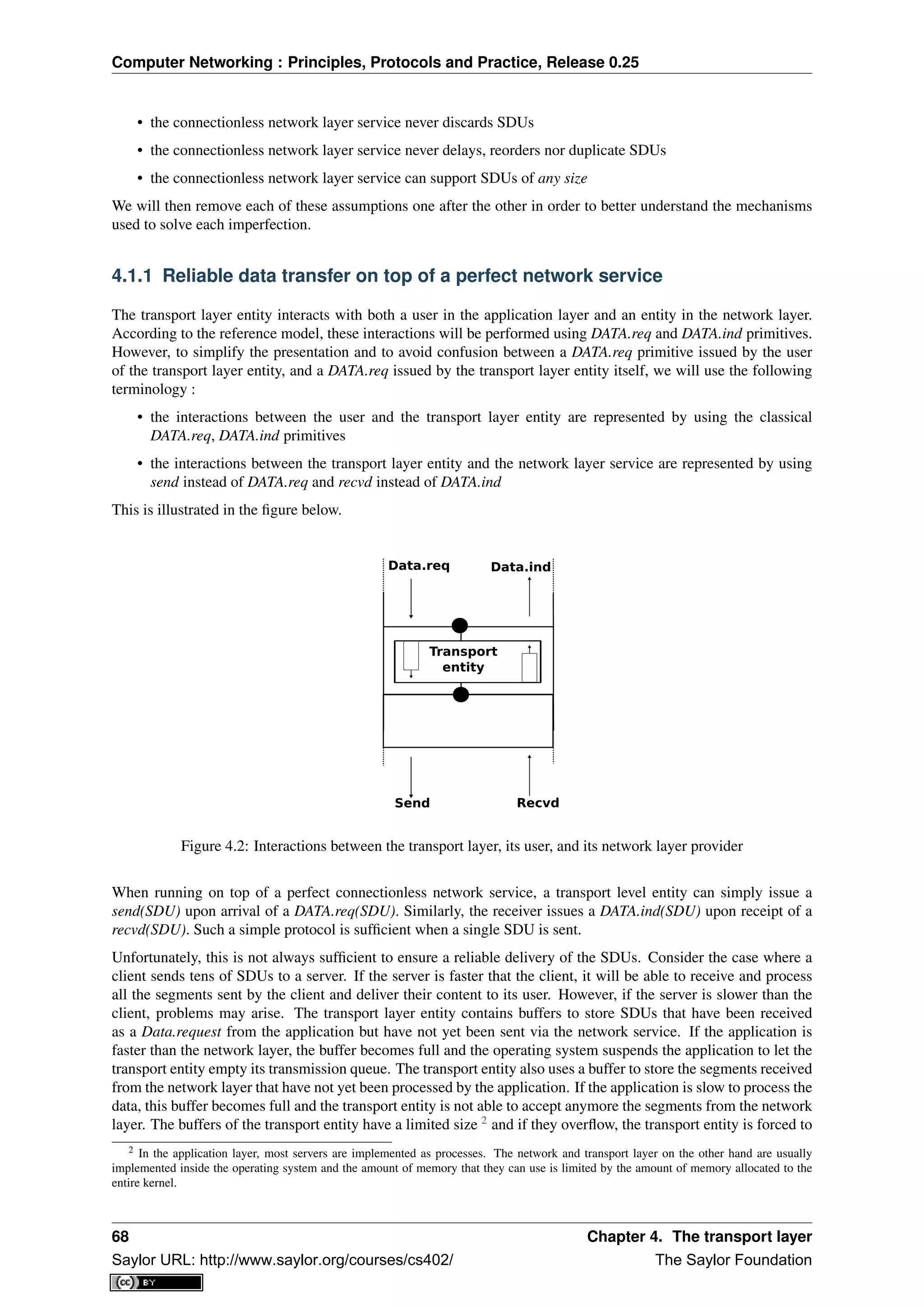
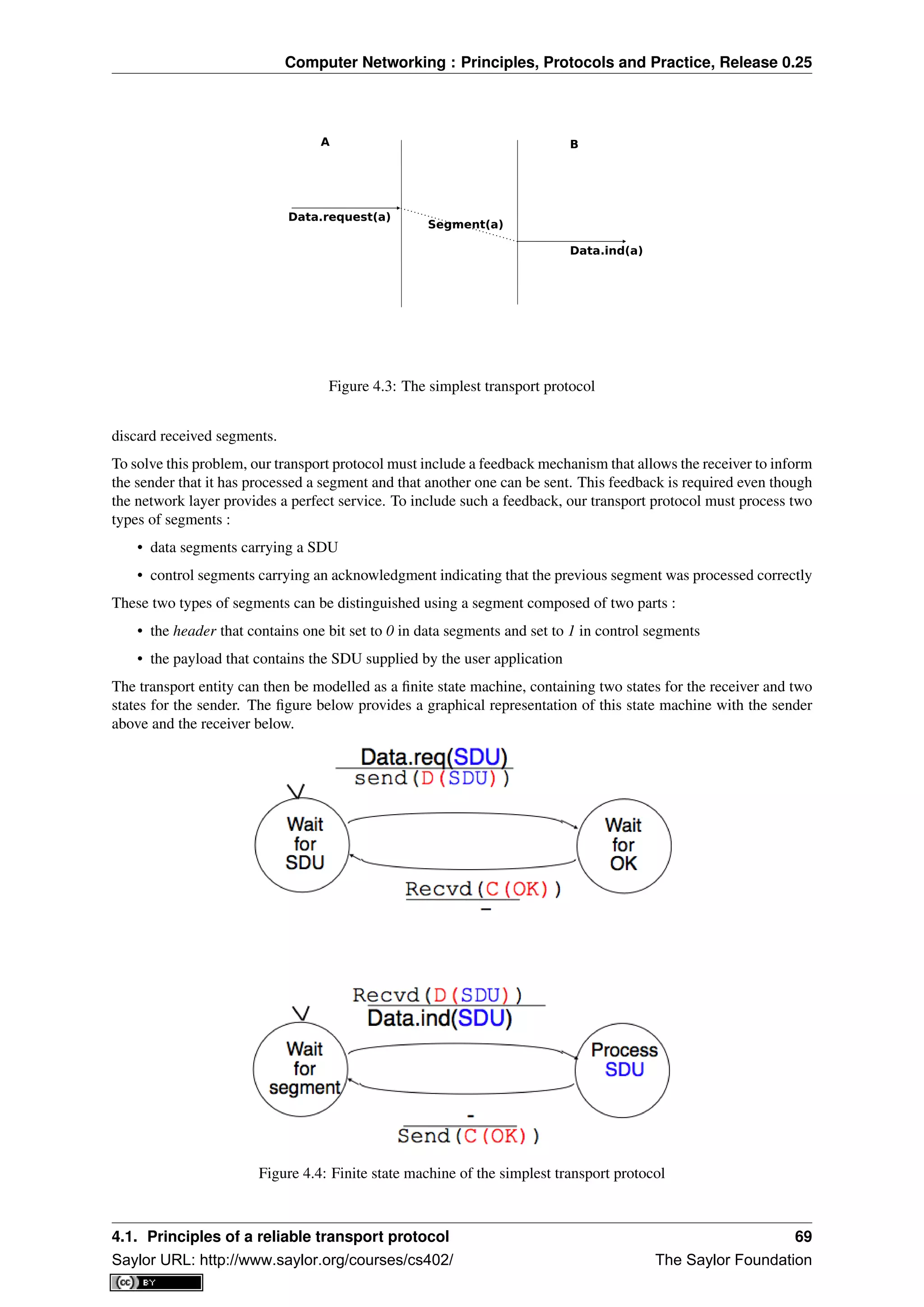
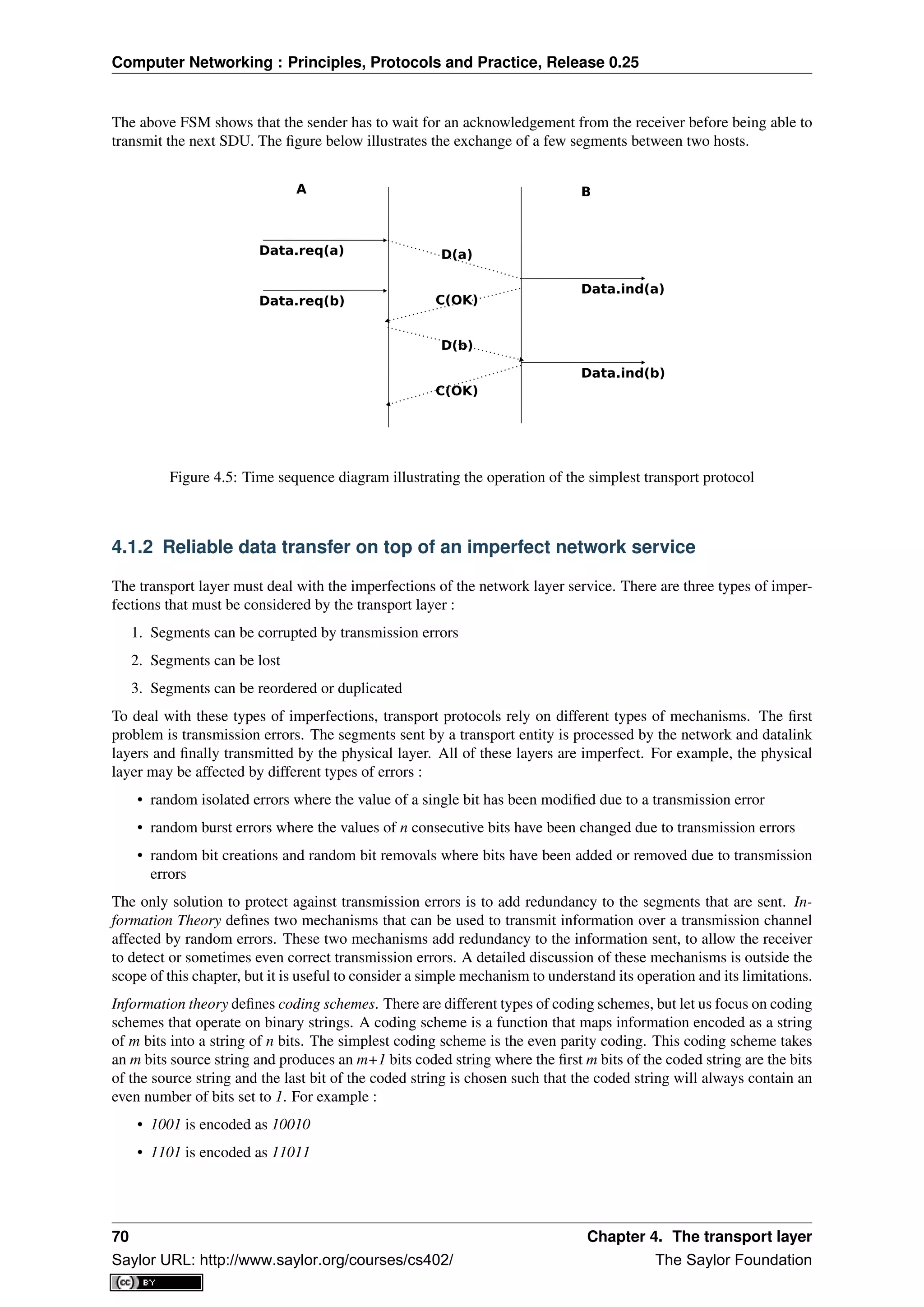
![Computer Networking : Principles, Protocols and Practice, Release 0.25
This parity scheme has been used in some RAMs as well as to encode characters sent over a serial line. It is easy
to show that this coding scheme allows the receiver to detect a single transmission error, but it cannot correct it.
However, if two or more bits are in error, the receiver may not always be able to detect the error.
Some coding schemes allow the receiver to correct some transmission errors. For example, consider the coding
scheme that encodes each source bit as follows :
• 1 is encoded as 111
• 0 is encoded as 000
For example, consider a sender that sends 111. If there is one bit in error, the receiver could receive 011 or 101 or
110. In these three cases, the receiver will decode the received bit pattern as a 1 since it contains a majority of bits
set to 1. If there are two bits in error, the receiver will not be able anymore to recover from the transmission error.
This simple coding scheme forces the sender to transmit three bits for each source bit. However, it allows the
receiver to correct single bit errors. More advanced coding systems that allow to recover from errors are used in
several types of physical layers.
Transport protocols use error detection schemes, but none of the widely used transport protocols rely on error
correction schemes. To detect errors, a segment is usually divided into two parts :
• a header that contains the fields used by the transport protocol to ensure reliable delivery. The header con-
tains a checksum or Cyclical Redundancy Check (CRC) [Williams1993] that is used to detect transmission
errors
• a payload that contains the user data passed by the application layer.
Some segment headers also include a length , which indicates the total length of the segment or the length of the
payload.
The simplest error detection scheme is the checksum. A checksum is basically an arithmetic sum of all the bytes
that a segment is composed of. There are different types of checksums. For example, an eight bit checksum can
be computed as the arithmetic sum of all the bytes of (both the header and trailer of) the segment. The checksum
is computed by the sender before sending the segment and the receiver verifies the checksum upon reception
of each segment. The receiver discards segments received with an invalid checksum. Checksums can be easily
implemented in software, but their error detection capabilities are limited. Cyclical Redundancy Checks (CRC)
have better error detection capabilities [SGP98], but require more CPU when implemented in software.
Note: Checksums, CRCs, ...
Most of the protocols in the TCP/IP protocol suite rely on the simple Internet checksum in order to verify that the
received segment has not been affected by transmission errors. Despite its popularity and ease of implementation,
the Internet checksum is not the only available checksum mechanism. Cyclical Redundancy Checks (CRC) are
very powerful error detection schemes that are used notably on disks, by many datalink layer protocols and file
formats such as zip or png. They can easily be implemented efficiently in hardware and have better error-detection
capabilities than the Internet checksum [SGP98] . However, when the first transport protocols were designed,
CRCs were considered to be too CPU-intensive for software implementations and other checksum mechanisms
were used instead. The TCP/IP community chose the Internet checksum, the OSI community chose the Fletcher
checksum [Sklower89] . Now, there are efficient techniques to quickly compute CRCs in software [Feldmeier95]
, the SCTP protocol initially chose the Adler-32 checksum but replaced it recently with a CRC (see RFC 3309).
The second imperfection of the network layer is that segments may be lost. As we will see later, the main cause
of packet losses in the network layer is the lack of buffers in intermediate routers. Since the receiver sends an
acknowledgement segment after having received each data segment, the simplest solution to deal with losses is to
use a retransmission timer. When the sender sends a segment, it starts a retransmission timer. The value of this
retransmission timer should be larger than the round-trip-time, i.e. the delay between the transmission of a data
segment and the reception of the corresponding acknowledgement. When the retransmission timer expires, the
sender assumes that the data segment has been lost and retransmits it. This is illustrated in the figure below.
Unfortunately, retransmission timers alone are not sufficient to recover from segment losses. Let us consider, as
an example, the situation depicted below where an acknowledgement is lost. In this case, the sender retransmits
4.1. Principles of a reliable transport protocol 71
Saylor URL: http://www.saylor.org/courses/cs402/ The Saylor Foundation](https://image.slidesharecdn.com/computer-networking-principles-bonaventure-1-30-31-otc1-150825141809-lva1-app6891/75/Computer-networking-principles-bonaventure-1-30-31-otc1-75-2048.jpg)
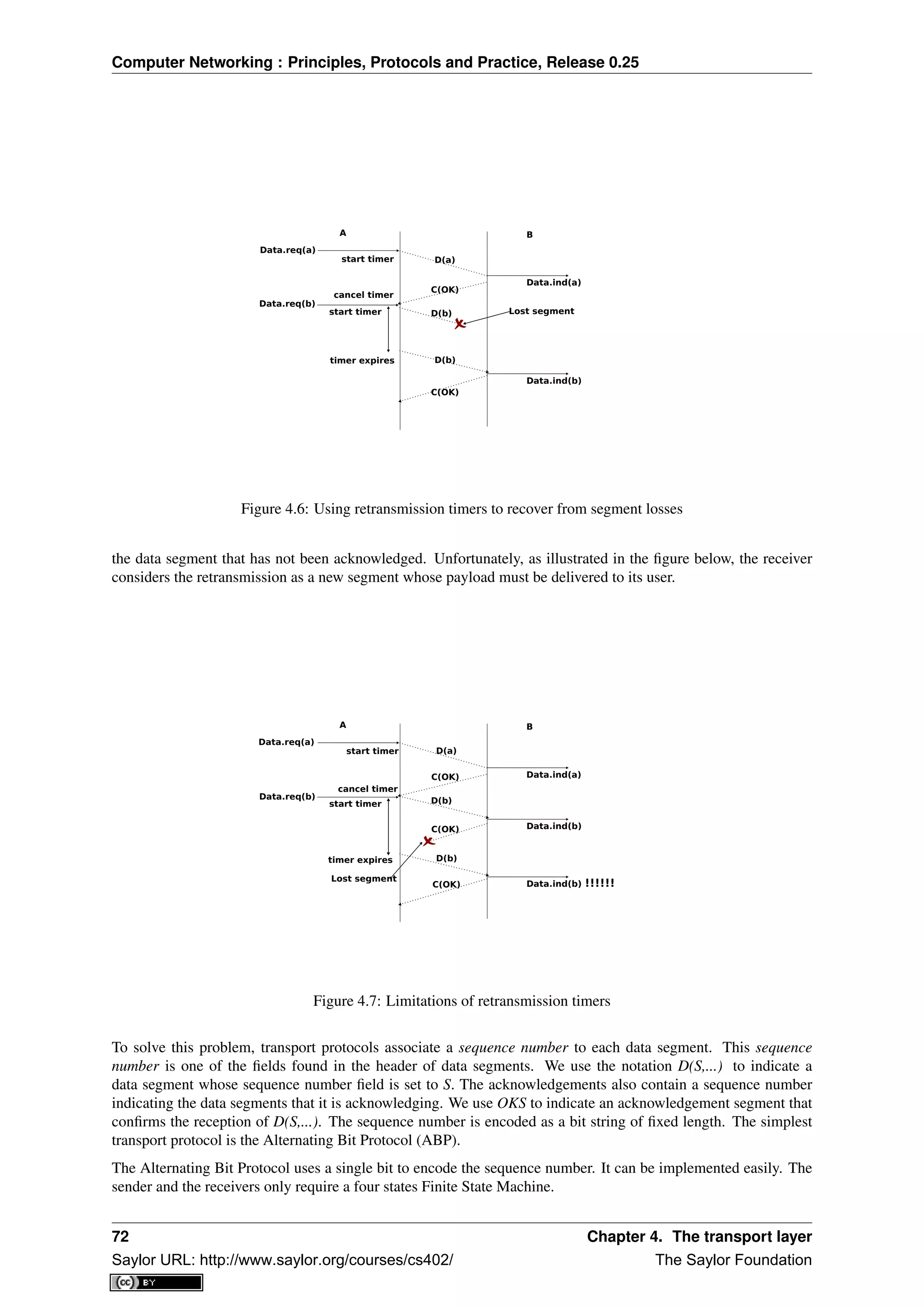
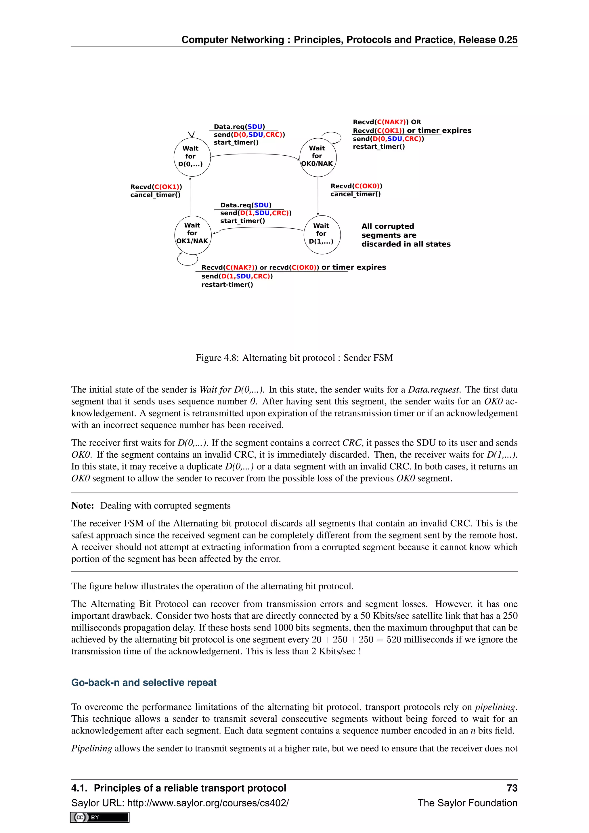
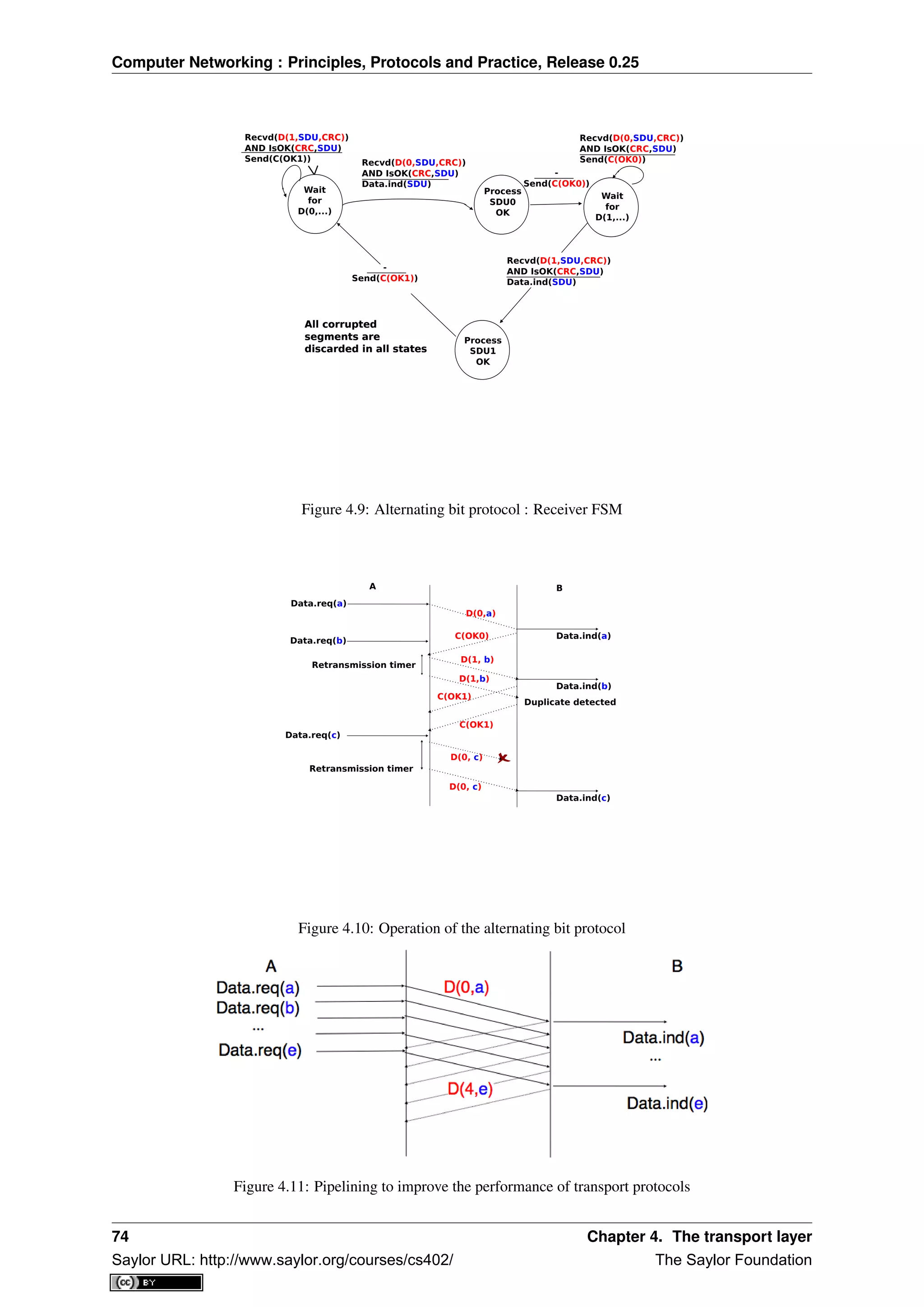
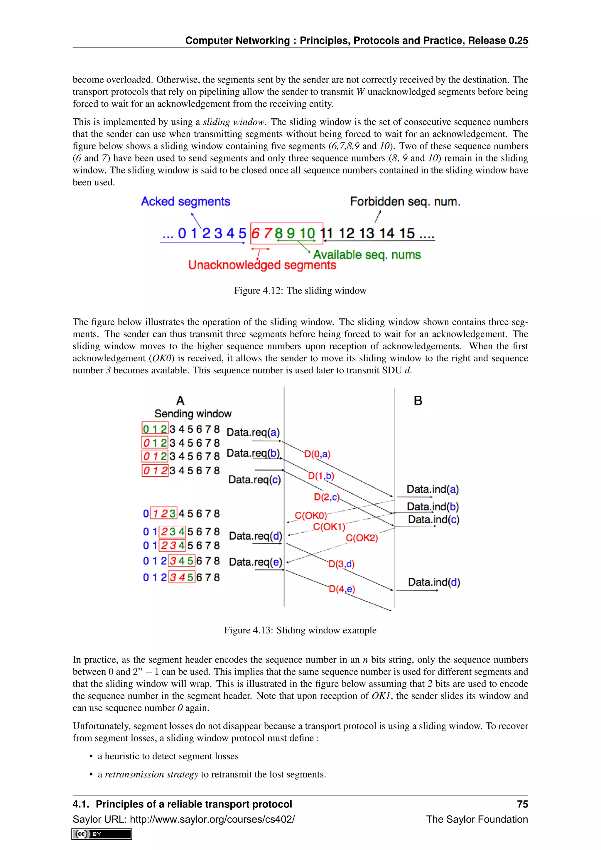
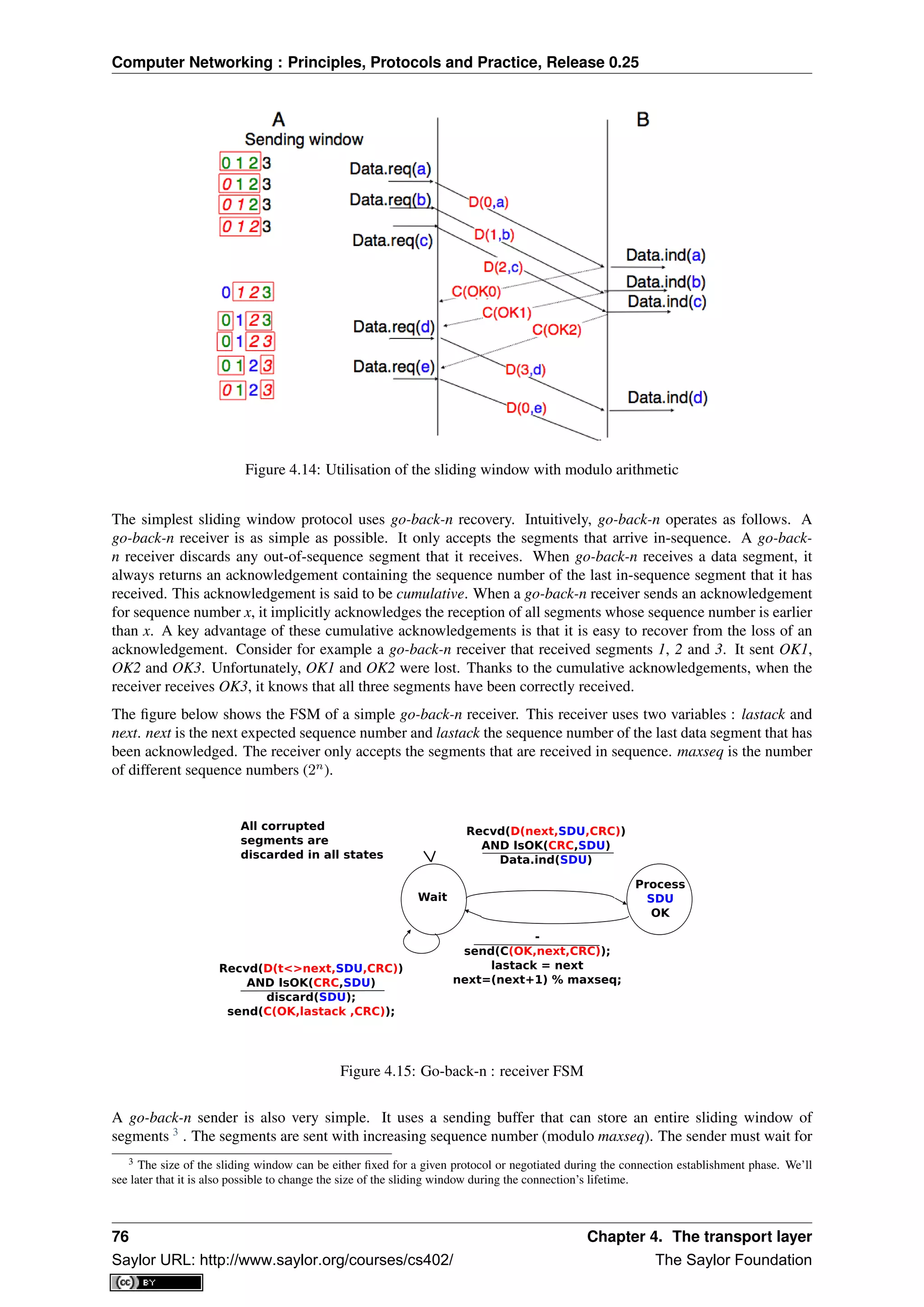
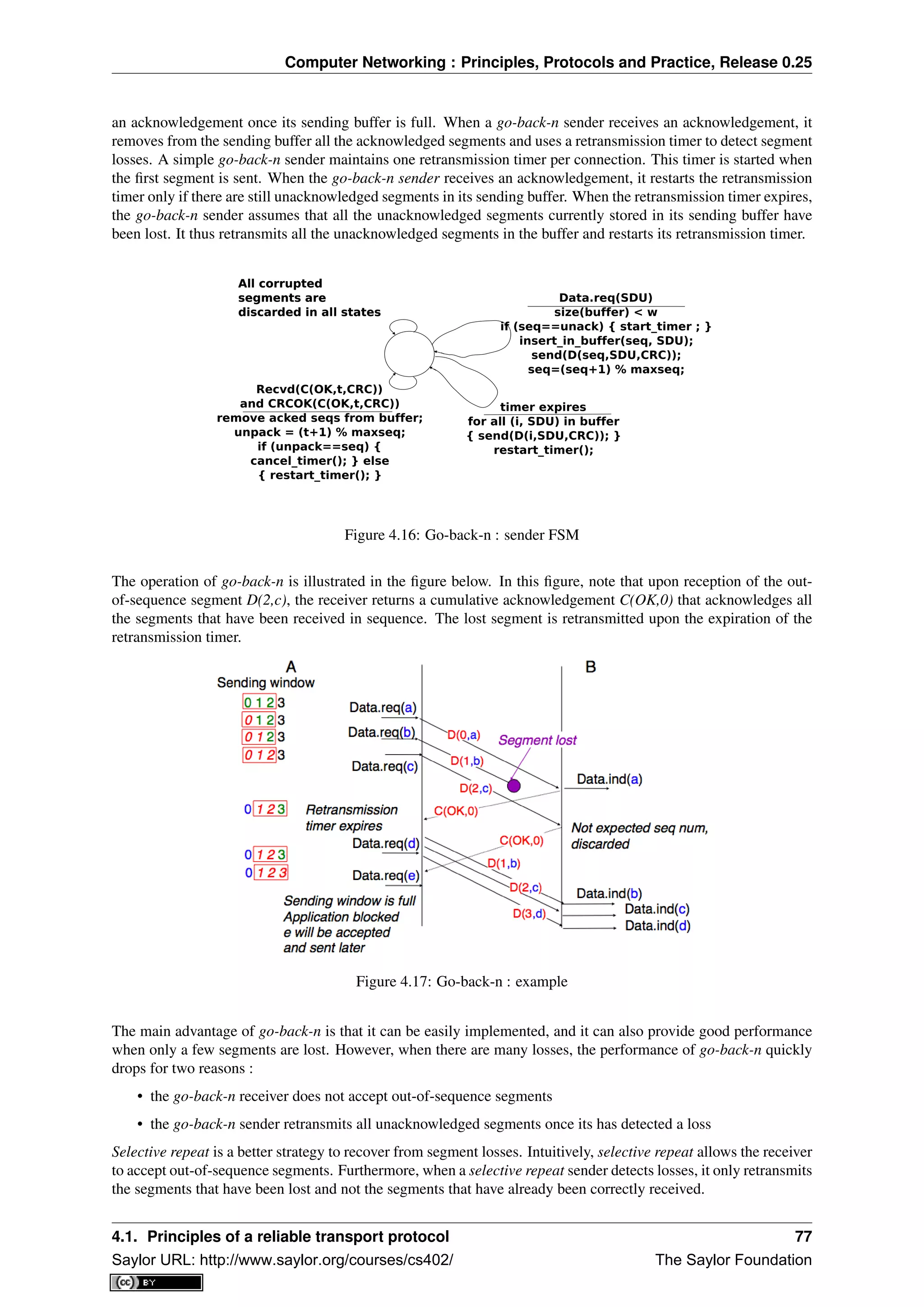
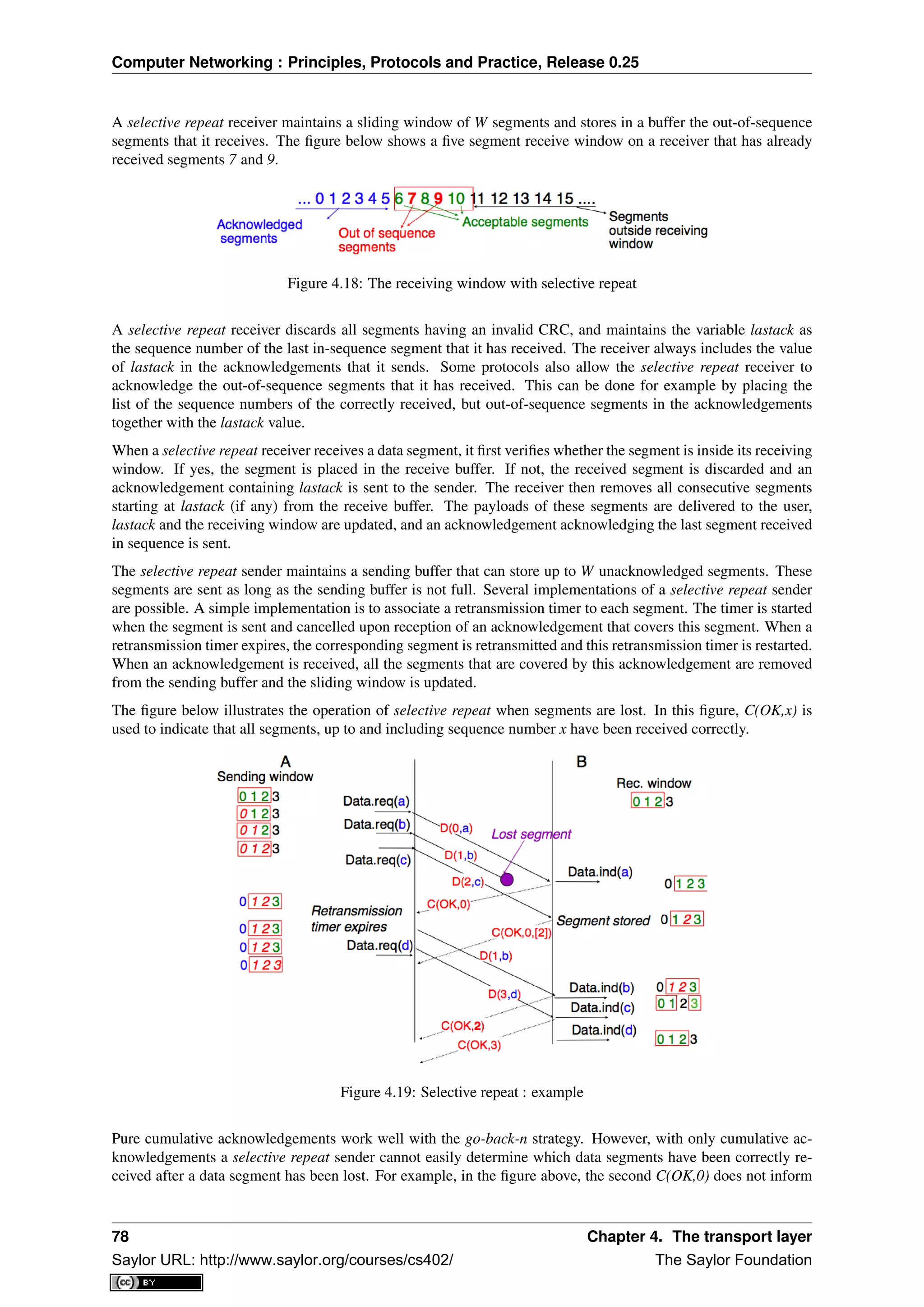
![Computer Networking : Principles, Protocols and Practice, Release 0.25
explicitly the sender of the reception of D(2,c) and the sender could retransmit this segment although it has al-
ready been received. A possible solution to improve the performance of selective repeat is to provide additional
information about the received segments in the acknowledgements that are returned by the receiver. For example,
the receiver could add in the returned acknowledgement the list of the sequence numbers of all segments that
have already been received. Such acknowledgements are sometimes called selective acknowledgements. This is
illustrated in the figure below.
In the figure above, when the sender receives C(OK,0,[2]), it knows that all segments up to and including D(0,...)
have been correctly received. It also knows that segment D(2,...) has been received and can cancel the retrans-
mission timer associated to this segment. However, this segment should not be removed from the sending buffer
before the reception of a cumulative acknowledgement (C(OK,2) in the figure above) that covers this segment.
Note: Maximum window size with go-back-n and selective repeat
A transport protocol that uses n bits to encode its sequence number can send up to 2n
different segments. However,
to ensure a reliable delivery of the segments, go-back-n and selective repeat cannot use a sending window of 2n
segments. Consider first go-back-n and assume that a sender sends 2n
segments. These segments are received
in-sequence by the destination, but all the returned acknowledgements are lost. The sender will retransmit all
segments and they will all be accepted by the receiver and delivered a second time to the user. It is easy to see that
this problem can be avoided if the maximum size of the sending window is 2n
− 1 segments. A similar problem
occurs with selective repeat. However, as the receiver accepts out-of-sequence segments, a sending window of
2n
− 1 segments is not sufficient to ensure a reliable delivery of all segments. It can be easily shown that to avoid
this problem, a selective repeat sender cannot use a window that is larger than 2n
2 segments.
Go-back-n or selective repeat are used by transport protocols to provide a reliable data transfer above an unreliable
network layer service. Until now, we have assumed that the size of the sliding window was fixed for the entire
lifetime of the connection. In practice a transport layer entity is usually implemented in the operating system and
shares memory with other parts of the system. Furthermore, a transport layer entity must support several (possibly
hundreds or thousands) of transport connections at the same time. This implies that the memory which can be
used to support the sending or the receiving buffer of a transport connection may change during the lifetime of the
connection 4
. Thus, a transport protocol must allow the sender and the receiver to adjust their window sizes.
To deal with this issue, transport protocols allow the receiver to advertise the current size of its receiving window
in all the acknowledgements that it sends. The receiving window advertised by the receiver bounds the size of
the sending buffer used by the sender. In practice, the sender maintains two state variables : swin, the size of its
sending window (that may be adjusted by the system) and rwin, the size of the receiving window advertised by
the receiver. At any time, the number of unacknowledged segments cannot be larger than min(swin,rwin) 5
. The
utilisation of dynamic windows is illustrated in the figure below.
The receiver may adjust its advertised receive window based on its current memory consumption, but also to limit
the bandwidth used by the sender. In practice, the receive buffer can also shrink as the application may not able to
process the received data quickly enough. In this case, the receive buffer may be completely full and the advertised
receive window may shrink to 0. When the sender receives an acknowledgement with a receive window set to 0,
it is blocked until it receives an acknowledgement with a positive receive window. Unfortunately, as shown in the
figure below, the loss of this acknowledgement could cause a deadlock as the sender waits for an acknowledgement
while the receiver is waiting for a data segment.
To solve this problem, transport protocols rely on a special timer : the persistence timer. This timer is started
by the sender whenever it receives an acknowledgement advertising a receive window set to 0. When the timer
expires, the sender retransmits an old segment in order to force the receiver to send a new acknowledgement, and
hence send the current receive window size.
To conclude our description of the basic mechanisms found in transport protocols, we still need to discuss the
impact of segments arriving in the wrong order. If two consecutive segments are reordered, the receiver relies on
their sequence numbers to reorder them in its receive buffer. Unfortunately, as transport protocols reuse the same
sequence number for different segments, if a segment is delayed for a prolonged period of time, it might still be
accepted by the receiver. This is illustrated in the figure below where segment D(1,b) is delayed.
4 For a discussion on how the sending buffer can change, see e.g. [SMM1998]
5 Note that if the receive window shrinks, it might happen that the sender has already sent a segment that is not anymore inside its window.
This segment will be discarded by the receiver and the sender will retransmit it later.
4.1. Principles of a reliable transport protocol 79
Saylor URL: http://www.saylor.org/courses/cs402/ The Saylor Foundation](https://image.slidesharecdn.com/computer-networking-principles-bonaventure-1-30-31-otc1-150825141809-lva1-app6891/75/Computer-networking-principles-bonaventure-1-30-31-otc1-83-2048.jpg)
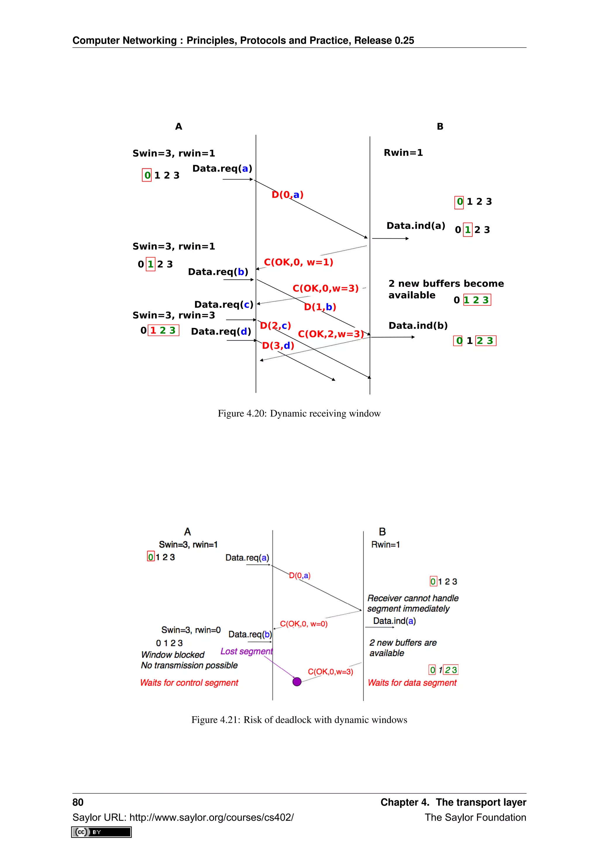
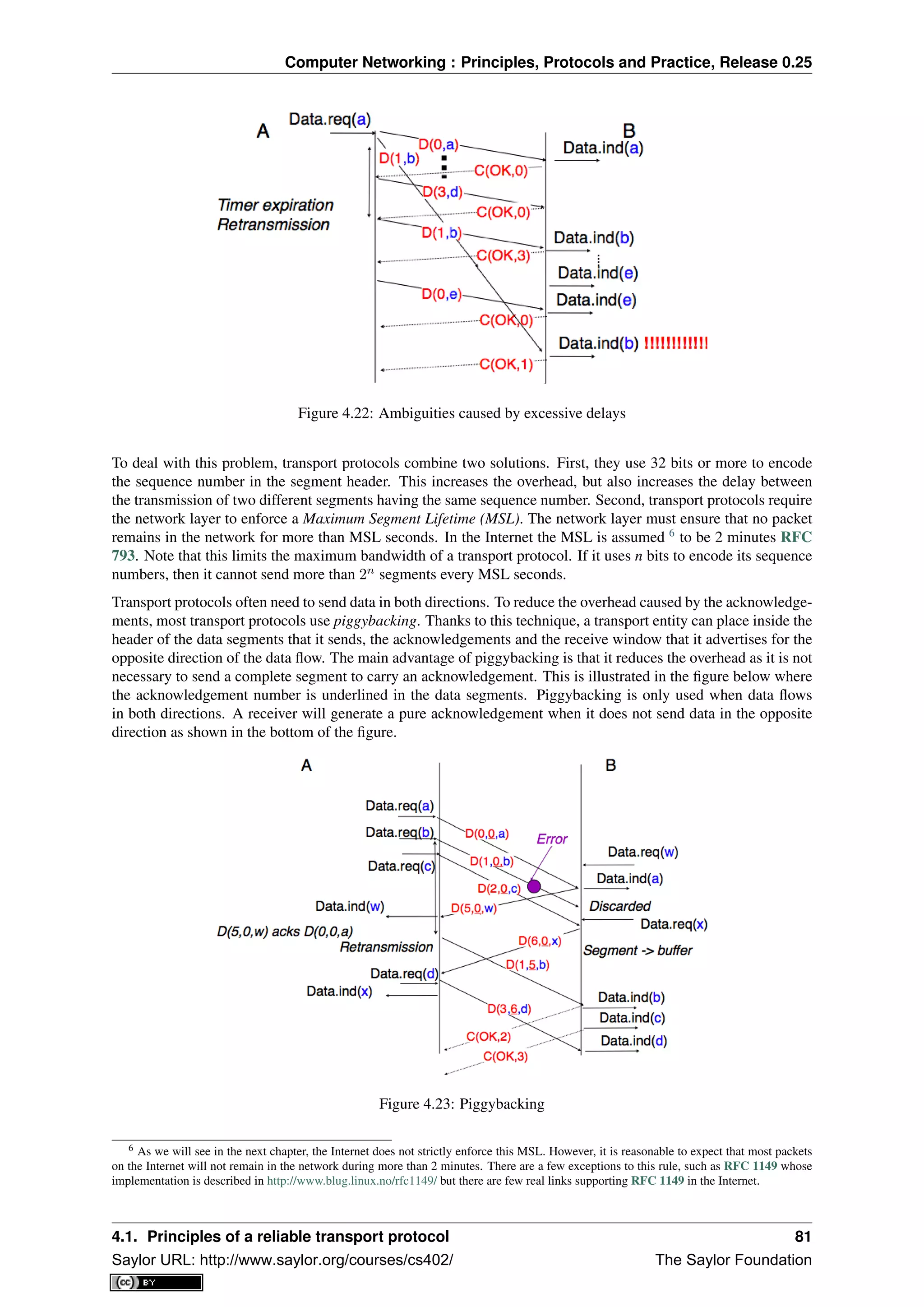
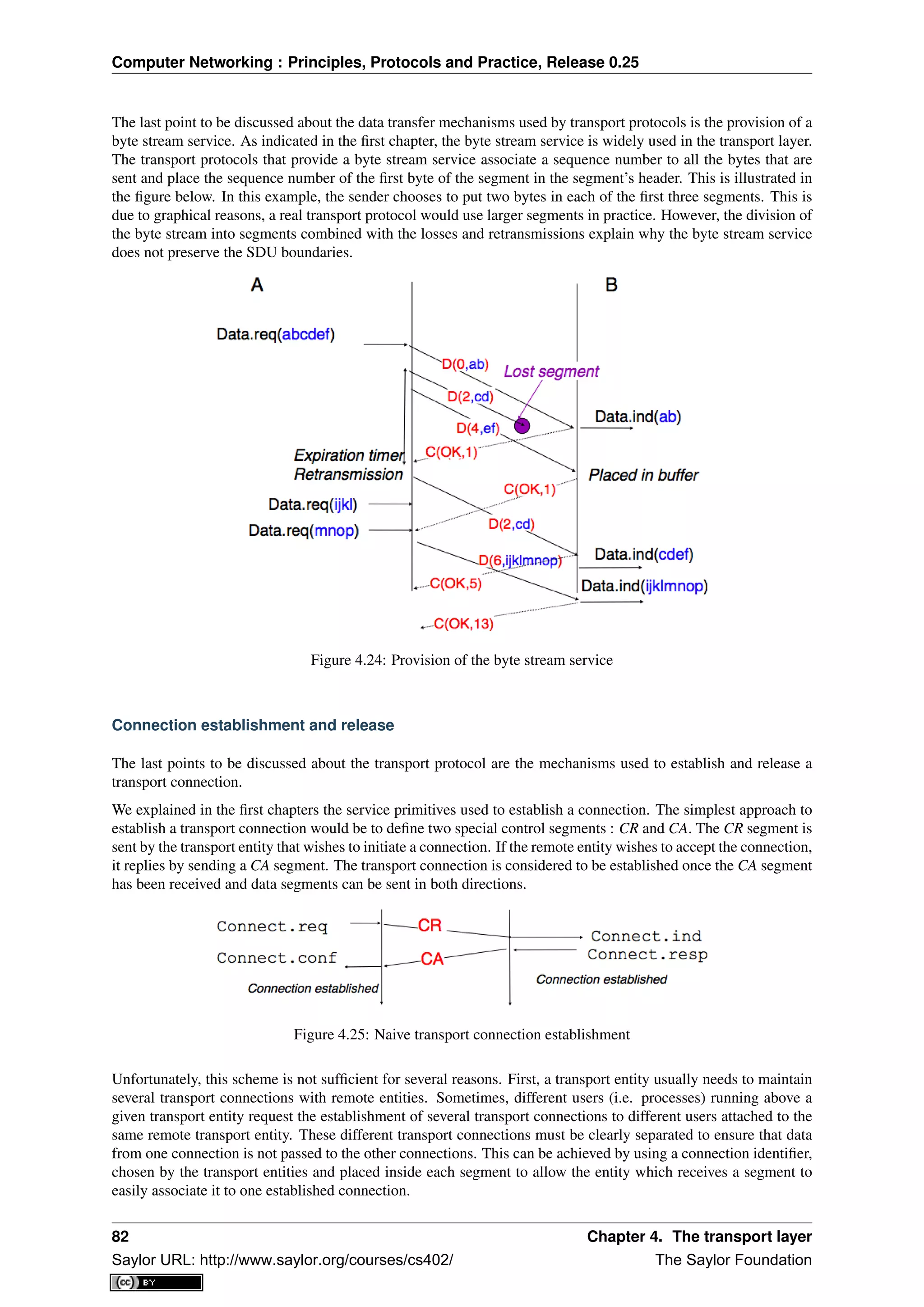
![Computer Networking : Principles, Protocols and Practice, Release 0.25
Second, as the network layer is imperfect, the CR or CA segment can be lost, delayed, or suffer from transmission
errors. To deal with these problems, the control segments must be protected by using a CRC or checksum to detect
transmission errors. Furthermore, since the CA segment acknowledges the reception of the CR segment, the CR
segment can be protected by using a retransmission timer.
Unfortunately, this scheme is not sufficient to ensure the reliability of the transport service. Consider for example
a short-lived transport connection where a single, but important transfer (e.g. money transfer from a bank account)
is sent. Such a short-lived connection starts with a CR segment acknowledged by a CA segment, then the data
segment is sent, acknowledged and the connection terminates. Unfortunately, as the network layer service is
unreliable, delays combined to retransmissions may lead to the situation depicted in the figure below, where a
delayed CR and data segments from a former connection are accepted by the receiving entity as valid segments,
and the corresponding data is delivered to the user. Duplicating SDUs is not acceptable, and the transport protocol
must solve this problem.
Figure 4.26: Duplicate transport connections ?
To avoid these duplicates, transport protocols require the network layer to bound the Maximum Segment Lifetime
(MSL). The organisation of the network must guarantee that no segment remains in the network for longer than
MSL seconds. On today’s Internet, MSL is expected to be 2 minutes. To avoid duplicate transport connections,
transport protocol entities must be able to safely distinguish between a duplicate CR segment and a new CR
segment, without forcing each transport entity to remember all the transport connections that it has established in
the past.
A classical solution to avoid remembering the previous transport connections to detect duplicates is to use a clock
inside each transport entity. This transport clock has the following characteristics :
• the transport clock is implemented as a k bits counter and its clock cycle is such that 2k
× cycle >>
MSL. Furthermore, the transport clock counter is incremented every clock cycle and after each connection
establishment. This clock is illustrated in the figure below.
• the transport clock must continue to be incremented even if the transport entity stops or reboots
Figure 4.27: Transport clock
It should be noted that transport clocks do not need and usually are not synchronised to the real-time clock.
Precisely synchronising real-time clocks is an interesting problem, but it is outside the scope of this document.
See [Mills2006] for a detailed discussion on synchronising the real-time clock.
4.1. Principles of a reliable transport protocol 83
Saylor URL: http://www.saylor.org/courses/cs402/ The Saylor Foundation](https://image.slidesharecdn.com/computer-networking-principles-bonaventure-1-30-31-otc1-150825141809-lva1-app6891/75/Computer-networking-principles-bonaventure-1-30-31-otc1-87-2048.jpg)
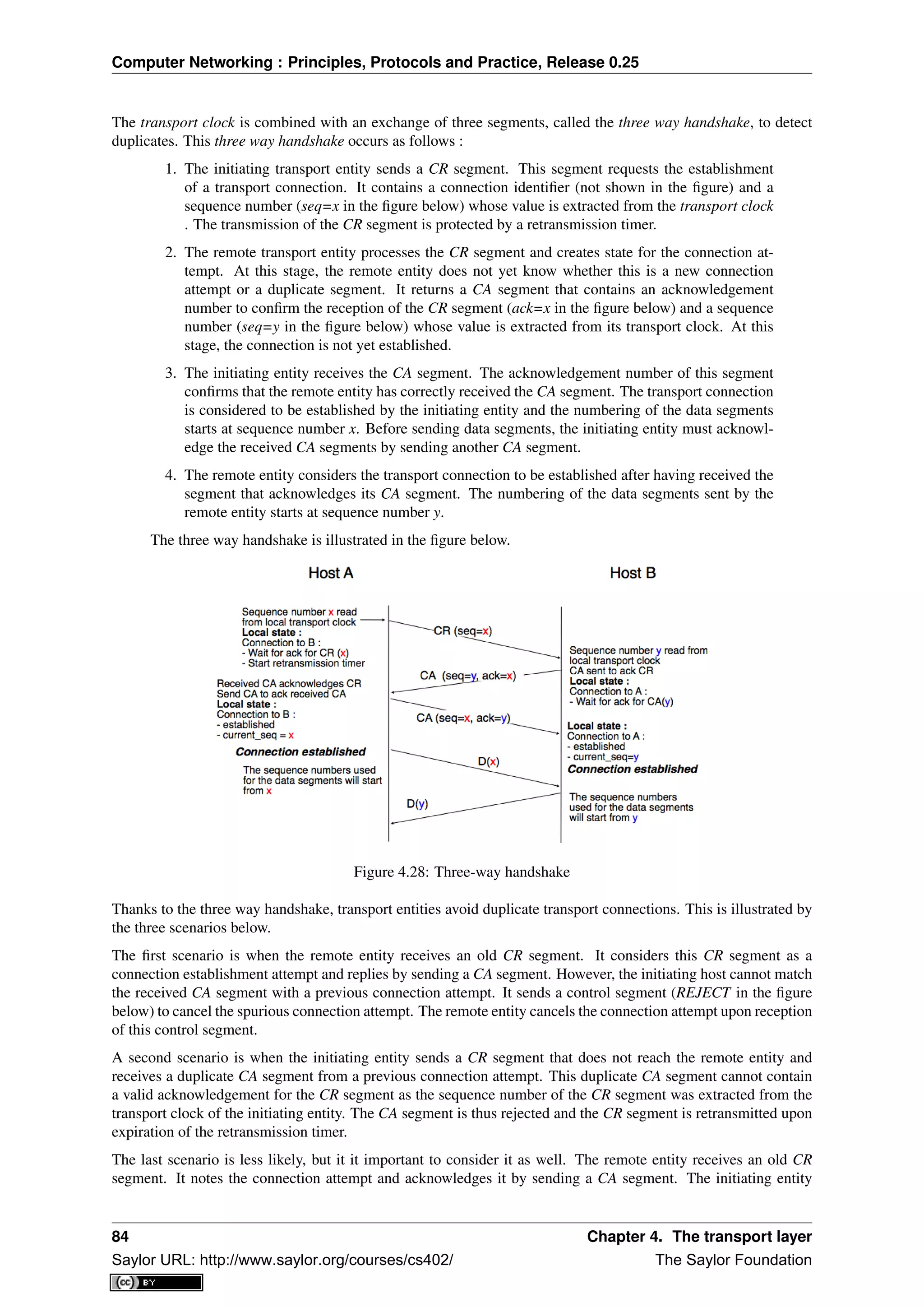
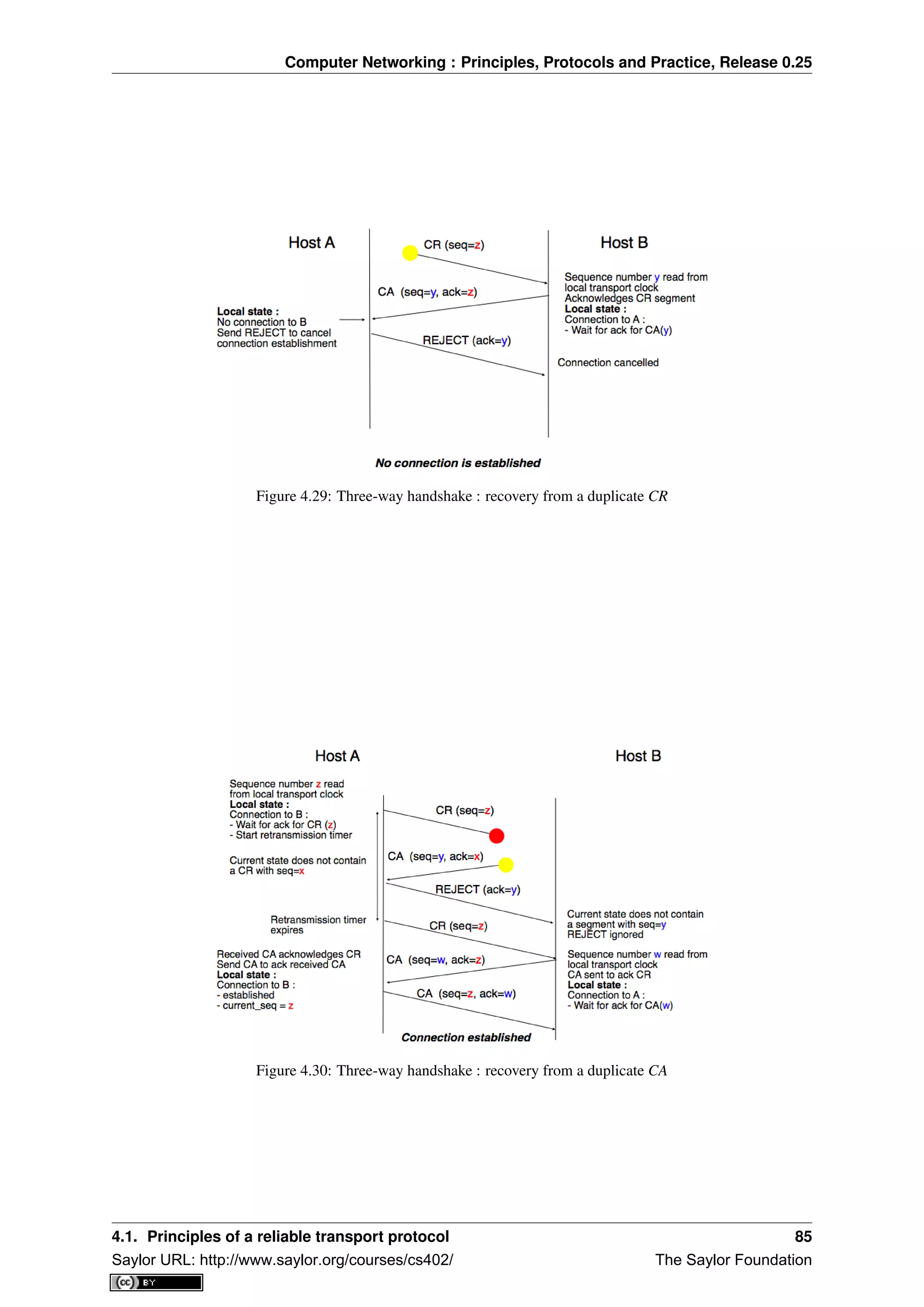
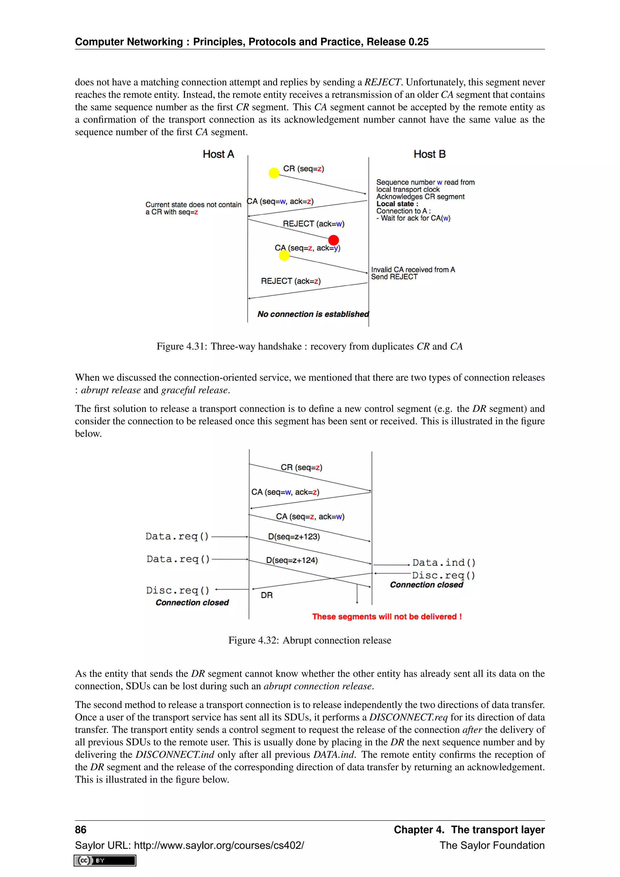
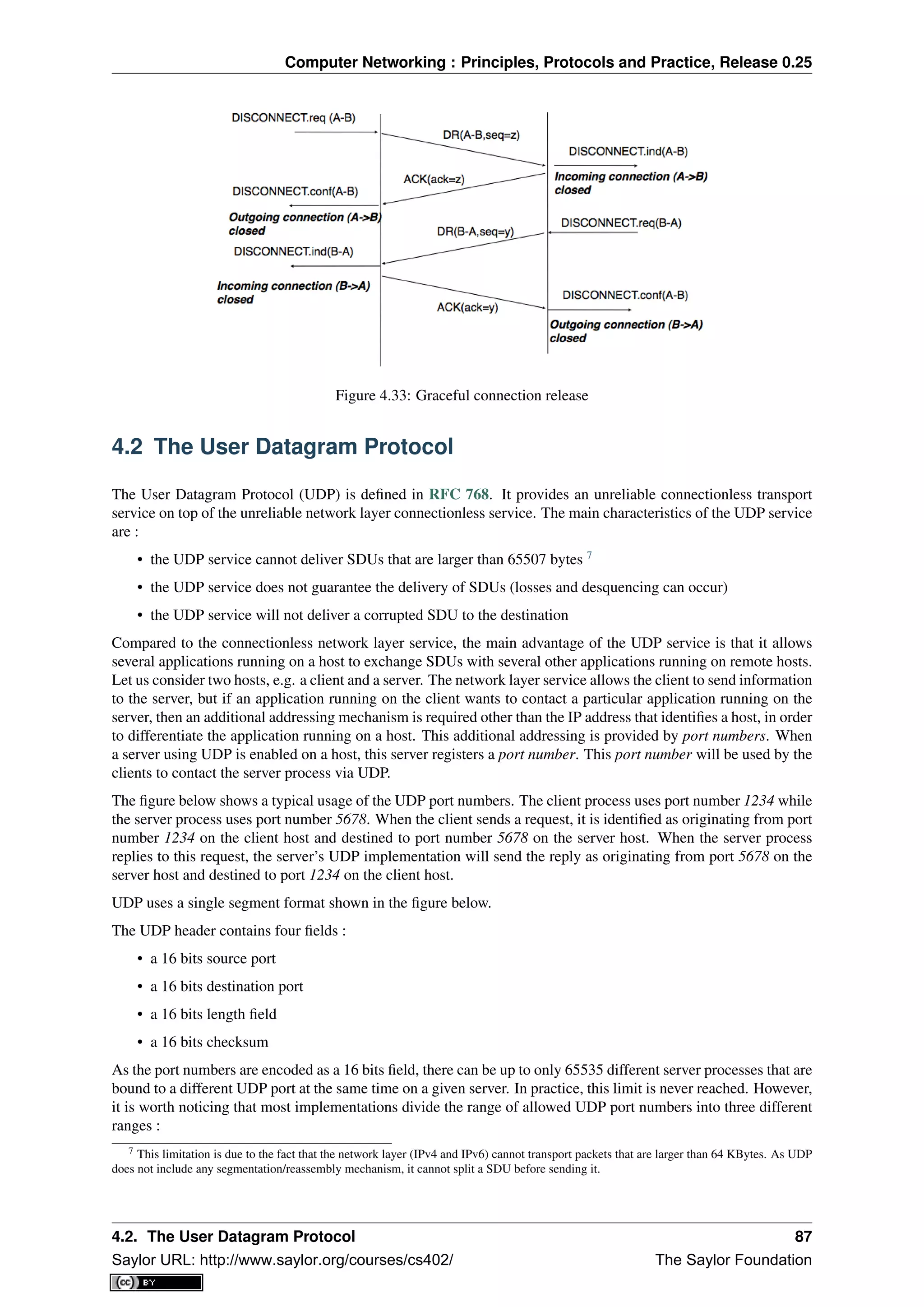
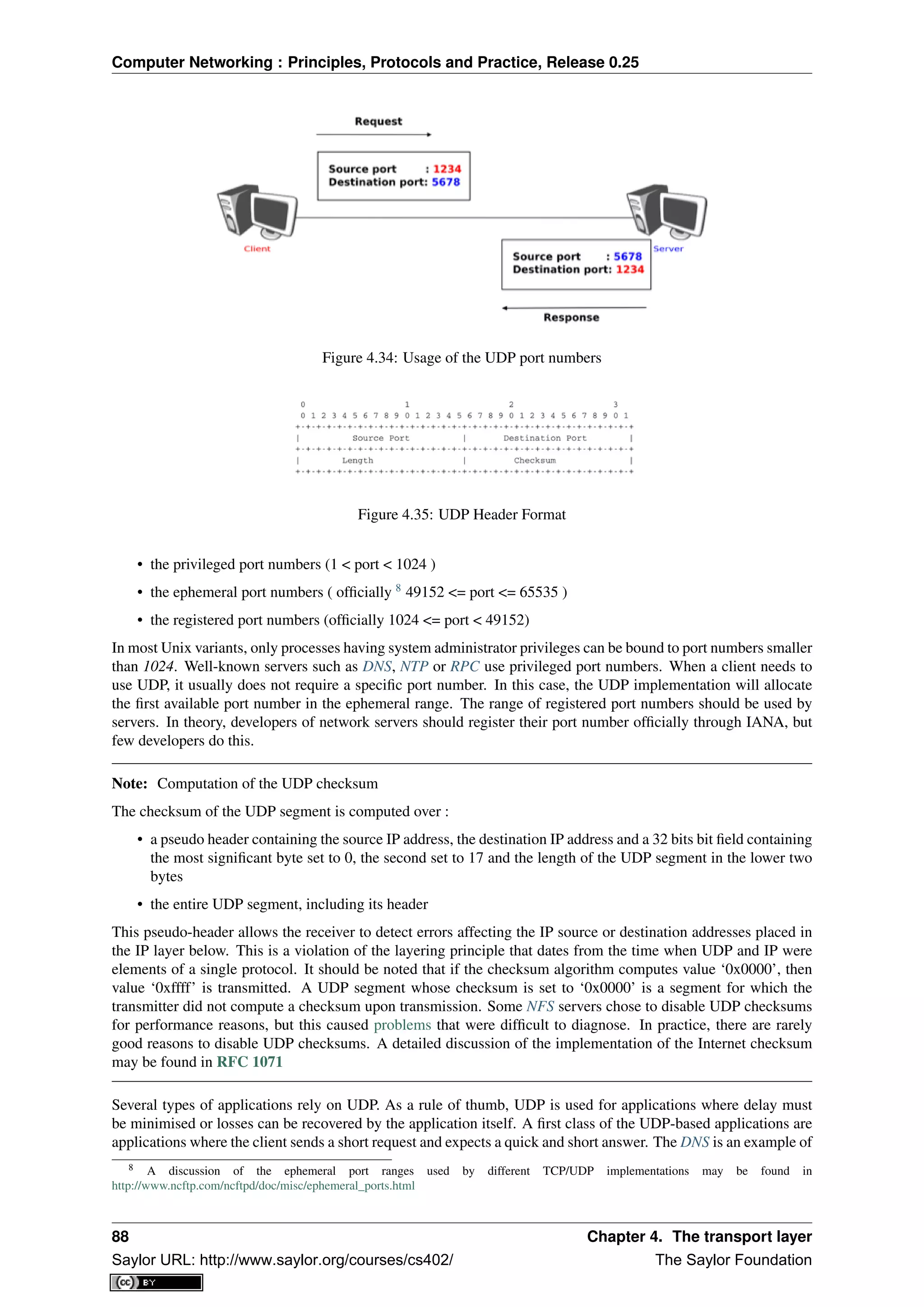
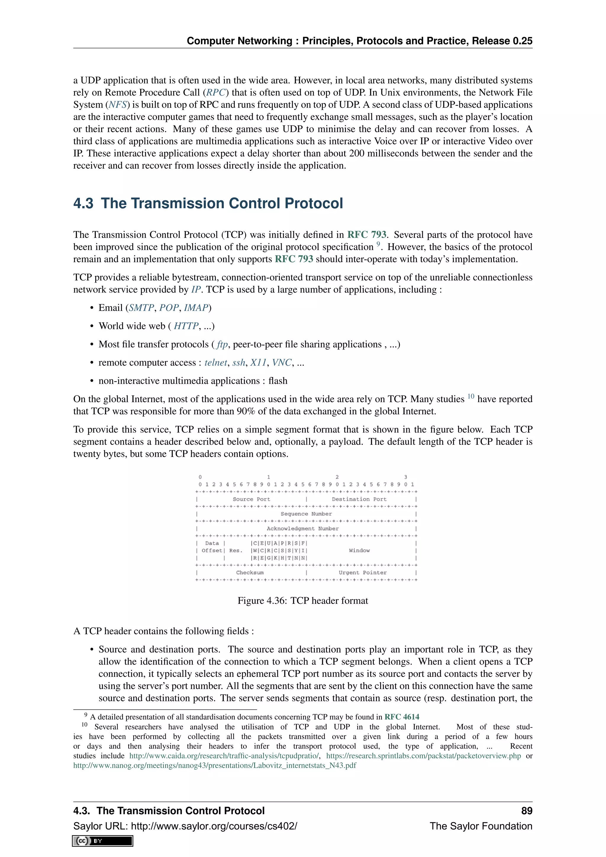
![Computer Networking : Principles, Protocols and Practice, Release 0.25
destination (resp. source) port of the segments sent by the client (see figure Utilization of the TCP source
and destination ports). A TCP connection is always identified by five pieces of information :
– the IP address of the client
– the IP address of the server
– the port chosen by the client
– the port chosen by the server
– TCP
• the sequence number (32 bits), acknowledgement number (32 bits) and window (16 bits) fields are used
to provide a reliable data transfer, using a window-based protocol. In a TCP bytestream, each byte of the
stream consumes one sequence number. Their utilisation will be described in more detail in section TCP
reliable data transfer
• the Urgent pointer is used to indicate that some data should be considered as urgent in a TCP bytestream.
However, it is rarely used in practice and will not be described here. Additional details about the utilisation
of this pointer may be found in RFC 793, RFC 1122 or [Stevens1994]
• the flags field contains a set of bit flags that indicate how a segment should be interpreted by the TCP entity
receiving it :
– the SYN flag is used during connection establishment
– the FIN flag is used during connection release
– the RST is used in case of problems or when an invalid segment has been received
– when the ACK flag is set, it indicates that the acknowledgment field contains a valid number. Other-
wise, the content of the acknowledgment field must be ignored by the receiver
– the URG flag is used together with the Urgent pointer
– the PSH flag is used as a notification from the sender to indicate to the receiver that it should pass all
the data it has received to the receiving process. However, in practice TCP implementations do not
allow TCP users to indicate when the PSH flag should be set and thus there are few real utilizations of
this flag.
• the checksum field contains the value of the Internet checksum computed over the entire TCP segment and
a pseudo-header as with UDP
• the Reserved field was initially reserved for future utilization. It is now used by RFC 3168.
• the TCP Header Length (THL) or Data Offset field is a four bits field that indicates the size of the TCP
header in 32 bit words. The maximum size of the TCP header is thus 64 bytes.
• the Optional header extension is used to add optional information to the TCP header. Thanks to this header
extension, it is possible to add new fields to the TCP header that were not planned in the original specifi-
cation. This allowed TCP to evolve since the early eighties. The details of the TCP header extension are
explained in sections TCP connection establishment and TCP reliable data transfer.
The rest of this section is organised as follows. We first explain the establishment and the release of a TCP
connection, then we discuss the mechanisms that are used by TCP to provide a reliable bytestream service. We
end the section with a discussion of network congestion and explain the mechanisms that TCP uses to avoid
congestion collapse.
4.3.1 TCP connection establishment
A TCP connection is established by using a three-way handshake. The connection establishment phase uses the
sequence number, the acknowledgment number and the SYN flag. When a TCP connection is established, the two
communicating hosts negotiate the initial sequence number to be used in both directions of the connection. For
this, each TCP entity maintains a 32 bits counter, which is supposed to be incremented by one at least every 4
90 Chapter 4. The transport layer
Saylor URL: http://www.saylor.org/courses/cs402/ The Saylor Foundation](https://image.slidesharecdn.com/computer-networking-principles-bonaventure-1-30-31-otc1-150825141809-lva1-app6891/75/Computer-networking-principles-bonaventure-1-30-31-otc1-94-2048.jpg)
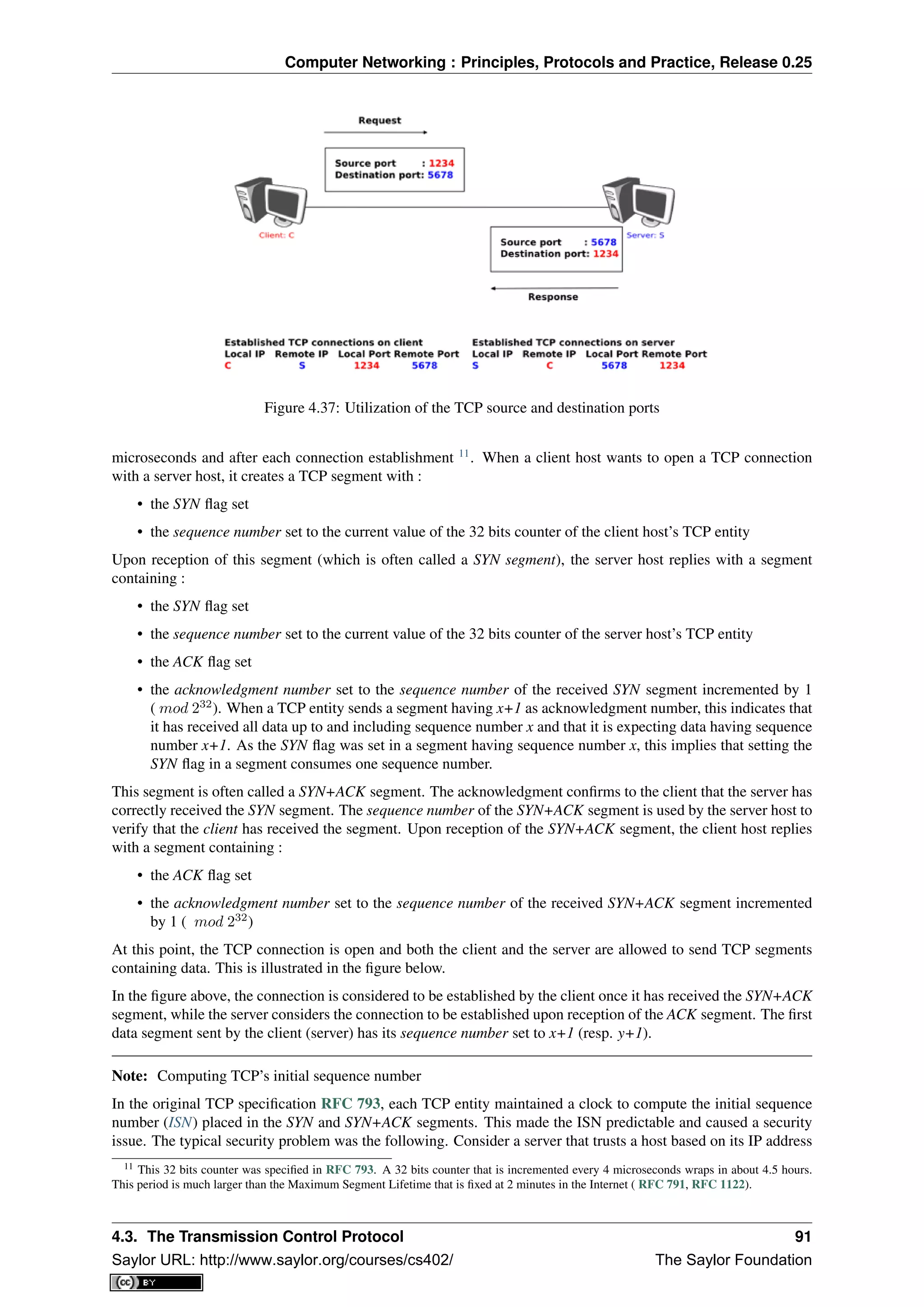
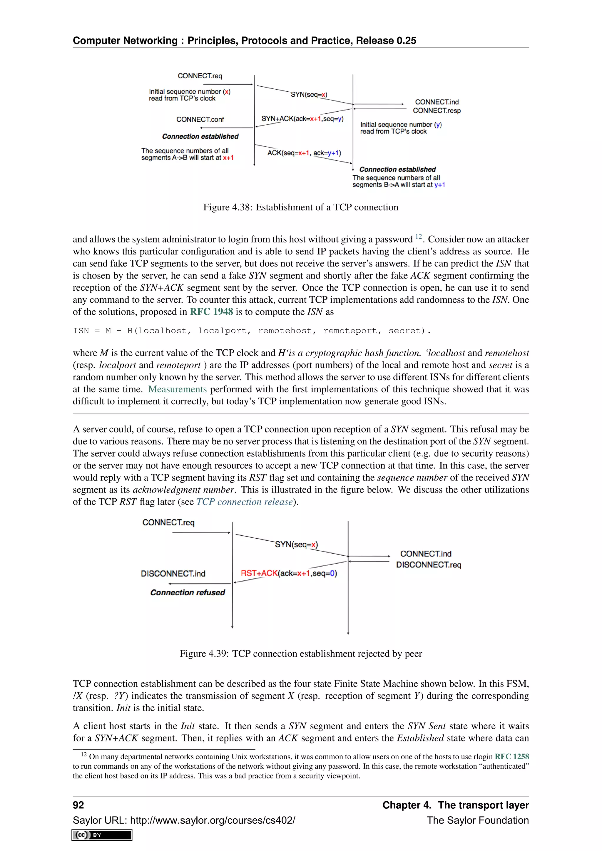
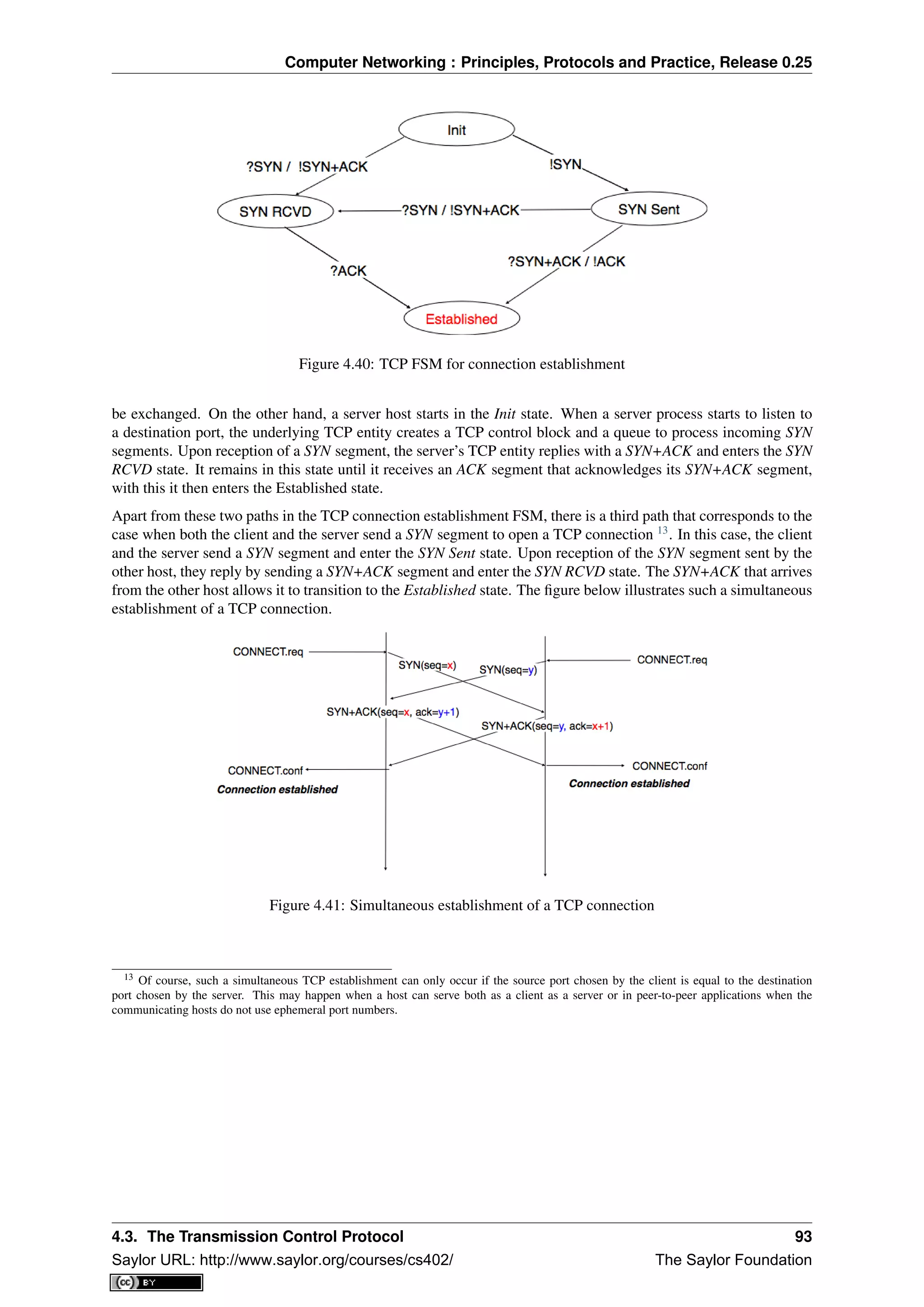
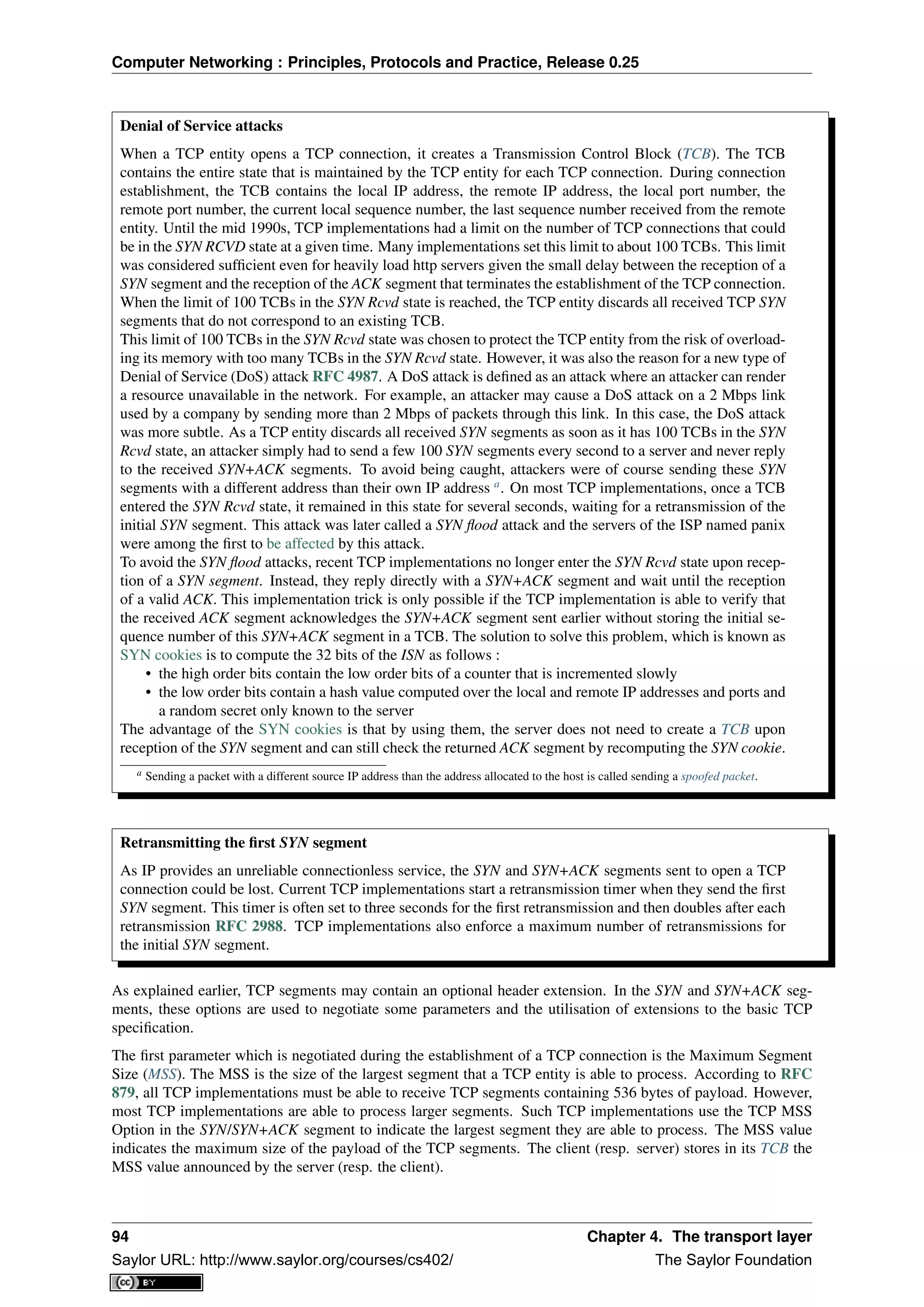
![Computer Networking : Principles, Protocols and Practice, Release 0.25
Another utilisation of TCP options during connection establishment is to enable TCP extensions. For example,
consider RFC 1323 (which is discussed in TCP reliable data transfer). RFC 1323 defines TCP extensions to
support timestamps and larger windows. If the client supports RFC 1323, it adds a RFC 1323 option to its SYN
segment. If the server understands this RFC 1323 option and wishes to use it, it replies with an RFC 1323
option in the SYN+ACK segment and the extension defined in RFC 1323 is used throughout the TCP connection.
Otherwise, if the server’s SYN+ACK does not contain the RFC 1323 option, the client is not allowed to use this
extension and the corresponding TCP header options throughout the TCP connection. TCP’s option mechanism
is flexible and it allows the extension of TCP while maintaining compatibility with older implementations.
The TCP options are encoded by using a Type Length Value format where :
• the first byte indicates the type of the option.
• the second byte indicates the total length of the option (including the first two bytes) in bytes
• the last bytes are specific for each type of option
RFC 793 defines the Maximum Segment Size (MSS) TCP option that must be understood by all TCP implemen-
tations. This option (type 2) has a length of 4 bytes and contains a 16 bits word that indicates the MSS supported
by the sender of the SYN segment. The MSS option can only be used in TCP segments having the SYN flag set.
RFC 793 also defines two special options that must be supported by all TCP implementations. The first option
is End of option. It is encoded as a single byte having value 0x00 and can be used to ensure that the TCP header
extension ends on a 32 bits boundary. The No-Operation option, encoded as a single byte having value 0x01, can
be used when the TCP header extension contains several TCP options that should be aligned on 32 bit boundaries.
All other options 14
are encoded by using the TLV format.
Note: The robustness principle
The handling of the TCP options by TCP implementations is one of the many applications of the robustness
principle which is usually attributed to Jon Postel and is often quoted as “Be liberal in what you accept, and
conservative in what you send” RFC 1122
Concerning the TCP options, the robustness principle implies that a TCP implementation should be able to accept
TCP options that it does not understand, in particular in received SYN segments, and that it should be able to parse
any received segment without crashing, even if the segment contains an unknown TCP option. Furthermore, a
server should not send in the SYN+ACK segment or later, options that have not been proposed by the client in the
SYN segment.
4.3.2 TCP connection release
TCP, like most connection-oriented transport protocols, supports two types of connection release :
• graceful connection release, where each TCP user can release its own direction of data transfer
• abrupt connection release, where either one user closes both directions of data transfer or one TCP entity
is forced to close the connection (e.g. because the remote host does not reply anymore or due to lack of
resources)
The abrupt connection release mechanism is very simple and relies on a single segment having the RST bit set. A
TCP segment containing the RST bit can be sent for the following reasons :
• a non-SYN segment was received for a non-existing TCP connection RFC 793
• by extension, some implementations respond with an RST segment to a segment that is received on an
existing connection but with an invalid header RFC 3360. This causes the corresponding connection to be
closed and has caused security attacks RFC 4953
• by extension, some implementations send an RST segment when they need to close an existing TCP con-
nection (e.g. because there are not enough resources to support this connection or because the remote host
is considered to be unreachable). Measurements have shown that this usage of TCP RST was widespread
[AW05]
14 The full list of all TCP options may be found at http://www.iana.org/assignments/tcp-parameters/
4.3. The Transmission Control Protocol 95
Saylor URL: http://www.saylor.org/courses/cs402/ The Saylor Foundation](https://image.slidesharecdn.com/computer-networking-principles-bonaventure-1-30-31-otc1-150825141809-lva1-app6891/75/Computer-networking-principles-bonaventure-1-30-31-otc1-99-2048.jpg)
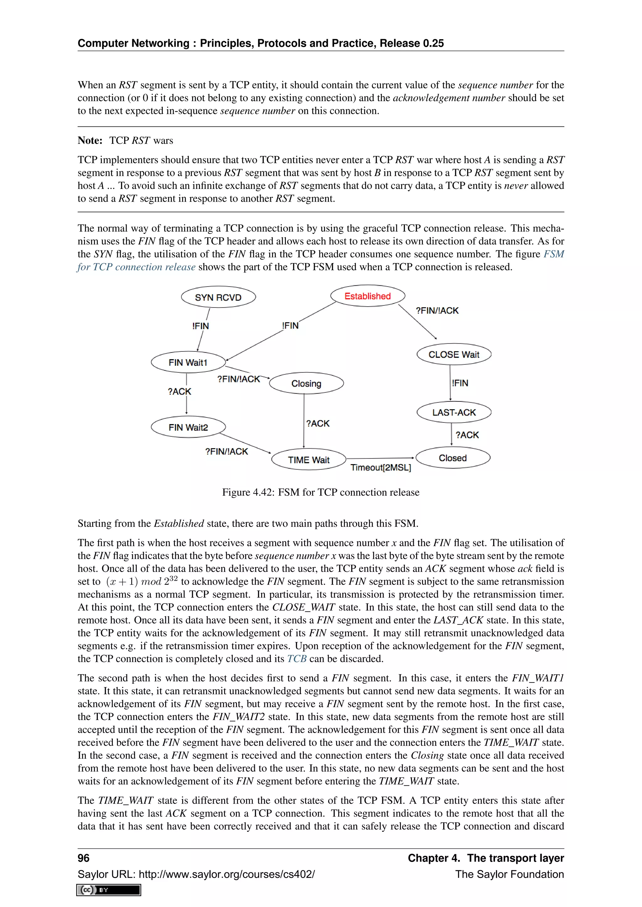
![Computer Networking : Principles, Protocols and Practice, Release 0.25
the corresponding TCB. After having sent the last ACK segment, a TCP connection enters the TIME_WAIT and
remains in this state for 2 ∗ MSL seconds. During this period, the TCB of the connection is maintained. This
ensures that the TCP entity that sent the last ACK maintains enough state to be able to retransmit this segment
if this ACK segment is lost and the remote host retransmits its last FIN segment or another one. The delay of
2 ∗ MSL seconds ensures that any duplicate segments on the connection would be handled correctly without
causing the transmission of an RST segment. Without the TIME_WAIT state and the 2 ∗ MSL seconds delay, the
connection release would not be graceful when the last ACK segment is lost.
Note: TIME_WAIT on busy TCP servers
The 2 ∗ MSL seconds delay in the TIME_WAIT state is an important operational problem on servers having
thousands of simultaneously opened TCP connections [FTY99]. Consider for example a busy web server that
processes 10.000 TCP connections every second. If each of these connections remain in the TIME_WAIT state
for 4 minutes, this implies that the server would have to maintain more than 2 million TCBs at any time. For this
reason, some TCP implementations prefer to perform an abrupt connection release by sending a RST segment to
close the connection [AW05] and immediately discard the corresponding TCB. However, if the RST segment is
lost, the remote host continues to maintain a TCB for a connection no longer exists. This optimisation reduces the
number of TCBs maintained by the host sending the RST segment but at the potential cost of increased processing
on the remote host when the RST segment is lost.
4.3.3 TCP reliable data transfer
The original TCP data transfer mechanisms were defined in RFC 793. Based on the experience of using TCP
on the growing global Internet, this part of the TCP specification has been updated and improved several times,
always while preserving the backward compatibility with older TCP implementations. In this section, we review
the main data transfer mechanisms used by TCP.
TCP is a window-based transport protocol that provides a bi-directional byte stream service. This has several
implications on the fields of the TCP header and the mechanisms used by TCP. The three fields of the TCP header
are :
• sequence number. TCP uses a 32 bits sequence number. The sequence number placed in the header of a
TCP segment containing data is the sequence number of the first byte of the payload of the TCP segment.
• acknowledgement number. TCP uses cumulative positive acknowledgements. Each TCP segment contains
the sequence number of the next byte that the sender of the acknowledgement expects to receive from the
remote host. In theory, the acknowledgement number is only valid if the ACK flag of the TCP header is set.
In practice almost all 15
TCP segments have their ACK flag set.
• window. a TCP receiver uses this 16 bits field to indicate the current size of its receive window expressed
in bytes.
Note: The Transmission Control Block
For each established TCP connection, a TCP implementation must maintain a Transmission Control Block (TCB).
A TCB contains all the information required to send and receive segments on this connection RFC 793. This
includes 16
:
• the local IP address
• the remote IP address
• the local TCP port number
• the remote TCP port number
• the current state of the TCP FSM
• the maximum segment size (MSS)
15 In practice, only the SYN segment do not have their ACK flag set.
16 A complete TCP implementation contains additional information in its TCB, notably to support the urgent pointer. However, this part of
TCP is not discussed in this book. Refer to RFC 793 and RFC 2140 for more details about the TCB.
4.3. The Transmission Control Protocol 97
Saylor URL: http://www.saylor.org/courses/cs402/ The Saylor Foundation](https://image.slidesharecdn.com/computer-networking-principles-bonaventure-1-30-31-otc1-150825141809-lva1-app6891/75/Computer-networking-principles-bonaventure-1-30-31-otc1-101-2048.jpg)
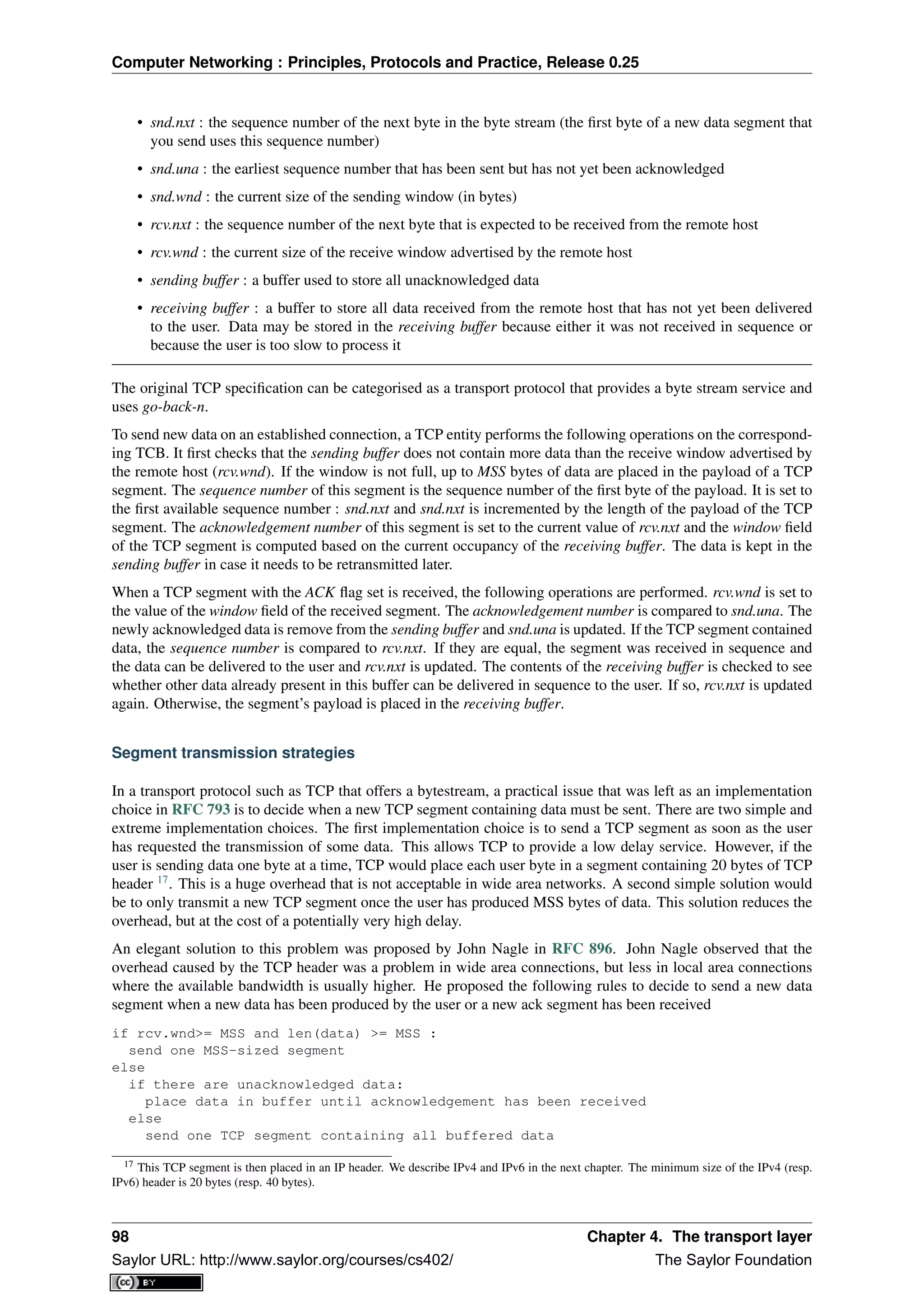
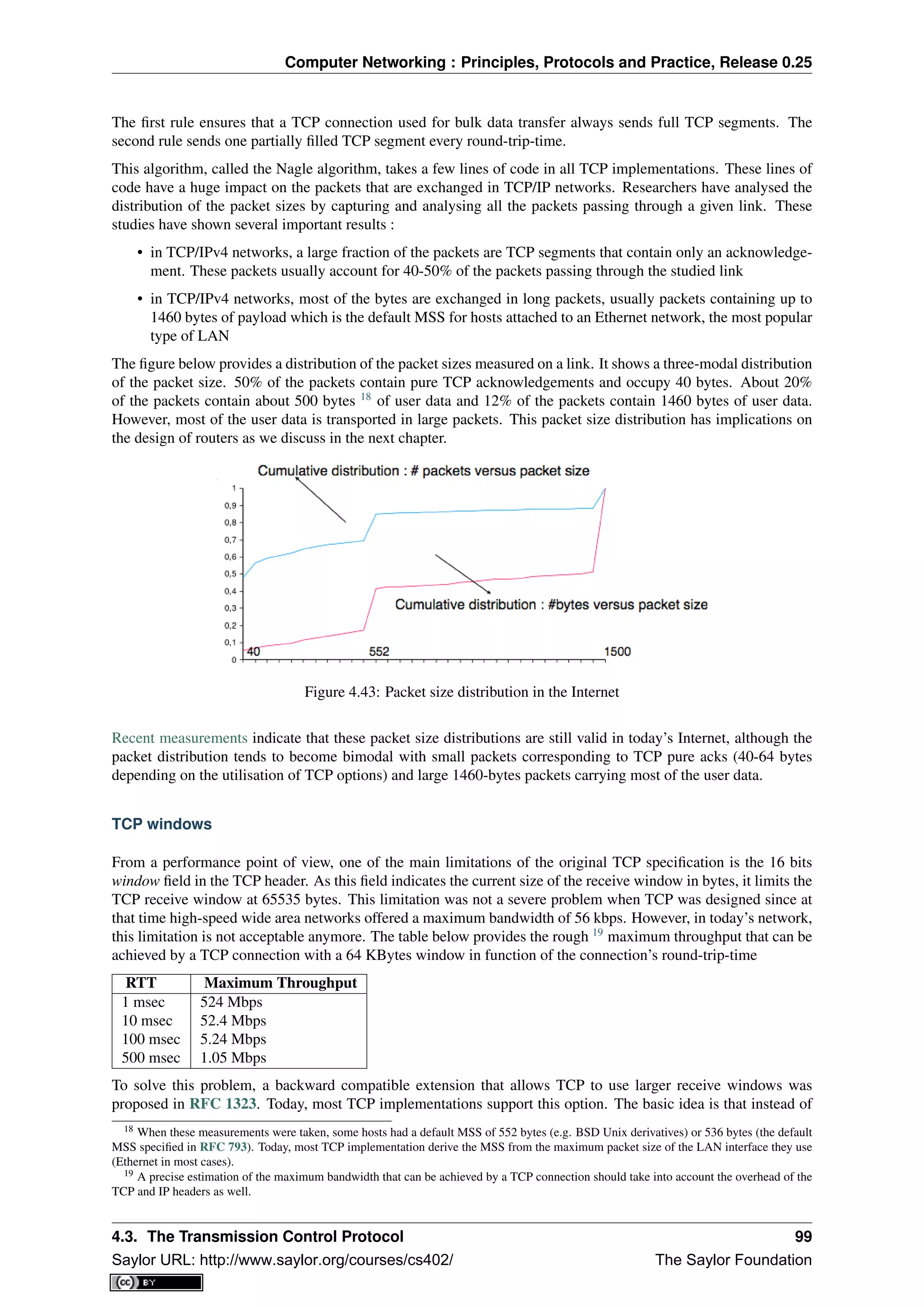
![Computer Networking : Principles, Protocols and Practice, Release 0.25
storing snd.wnd and rcv.wnd as 16 bits integers in the TCB, they should be stored as 32 bits integers. As the TCP
segment header only contains 16 bits to place the window field, it is impossible to copy the value of snd.wnd in
each sent TCP segment. Instead the header contains snd.wnd >> S where S is the scaling factor ( 0 ≤ S ≤ 14)
negotiated during connection establishment. The client adds its proposed scaling factor as a TCP option in the
SYN segment. If the server supports RFC 1323, it places in the SYN+ACK segment the scaling factor that it uses
when advertising its own receive window. The local and remote scaling factors are included in the TCB. If the
server does not support RFC 1323, it ignores the received option and no scaling is applied.
By using the window scaling extensions defined in RFC 1323, TCP implementations can use a receive buffer
of up to 1 GByte. With such a receive buffer, the maximum throughput that can be achieved by a single TCP
connection becomes :
RTT Maximum Throughput
1 msec 8590 Gbps
10 msec 859 Gbps
100 msec 86 Gbps
500 msec 17 Gbps
These throughputs are acceptable in today’s networks. However, there are already servers having 10 Gbps in-
terfaces... Early TCP implementations had fixed receiving and sending buffers 20
. Today’s high performance
implementations are able to automatically adjust the size of the sending and receiving buffer to better support high
bandwidth flows [SMM1998]
TCP’s retransmission timeout
In a go-back-n transport protocol such as TCP, the retransmission timeout must be correctly set in order to achieve
good performance. If the retransmission timeout expires too early, then bandwidth is wasted by retransmitting
segments that have already been correctly received; whereas if the retransmission timeout expires too late, then
bandwidth is wasted because the sender is idle waiting for the expiration of its retransmission timeout.
A good setting of the retransmission timeout clearly depends on an accurate estimation of the round-trip-time of
each TCP connection. The round-trip-time differs between TCP connections, but may also change during the
lifetime of a single connection. For example, the figure below shows the evolution of the round-trip-time between
two hosts during a period of 45 seconds.
Figure 4.44: Evolution of the round-trip-time between two hosts
The easiest solution to measure the round-trip-time on a TCP connection is to measure the delay between the
transmission of a data segment and the reception of a corresponding acknowledgement 21
. As illustrated in the
20 See http://fasterdata.es.net/tuning.html for more information on how to tune a TCP implementation
21 In theory, a TCP implementation could store the timestamp of each data segment transmitted and compute a new estimate for the round-
trip-time upon reception of the corresponding acknowledgement. However, using such frequent measurements introduces a lot of noise in
practice and many implementations still measure the round-trip-time once per round-trip-time by recording the transmission time of one
segment at a time RFC 2988
100 Chapter 4. The transport layer
Saylor URL: http://www.saylor.org/courses/cs402/ The Saylor Foundation](https://image.slidesharecdn.com/computer-networking-principles-bonaventure-1-30-31-otc1-150825141809-lva1-app6891/75/Computer-networking-principles-bonaventure-1-30-31-otc1-104-2048.jpg)
![Computer Networking : Principles, Protocols and Practice, Release 0.25
figure below, this measurement works well when there are no segment losses.
Figure 4.45: How to measure the round-trip-time ?
However, when a data segment is lost, as illustrated in the bottom part of the figure, the measurement is ambiguous
as the sender cannot determine whether the received acknowledgement was triggered by the first transmission of
segment 123 or its retransmission. Using incorrect round-trip-time estimations could lead to incorrect values of
the retransmission timeout. For this reason, Phil Karn and Craig Partridge proposed, in [KP91], to ignore the
round-trip-time measurements performed during retransmissions.
To avoid this ambiguity in the estimation of the round-trip-time when segments are retransmitted, recent TCP
implementations rely on the timestamp option defined in RFC 1323. This option allows a TCP sender to place
two 32 bit timestamps in each TCP segment that it sends. The first timestamp, TS Value (TSval) is chosen by the
sender of the segment. It could for example be the current value of its real-time clock 22
. The second value, TS
Echo Reply (TSecr), is the last TSval that was received from the remote host and stored in the TCB. The figure
below shows how the utilization of this timestamp option allows for the disambiguation of the round-trip-time
measurement when there are retransmissions.
Figure 4.46: Disambiguating round-trip-time measurements with the RFC 1323 timestamp option
Once the round-trip-time measurements have been collected for a given TCP connection, the TCP entity must
compute the retransmission timeout. As the round-trip-time measurements may change during the lifetime of a
connection, the retransmission timeout may also change. At the beginning of a connection 23
, the TCP entity that
sends a SYN segment does not know the round-trip-time to reach the remote host and the initial retransmission
timeout is usually set to 3 seconds RFC 2988.
The original TCP specification proposed in RFC 793 to include two additional variables in the TCB :
• srtt : the smoothed round-trip-time computed as srrt = (α × srtt) + ((1 − α) × rtt) where rtt is the
round-trip-time measured according to the above procedure and α a smoothing factor (e.g. 0.8 or 0.9)
22 Some security experts have raised concerns that using the real-time clock to set the TSval in the timestamp option can leak information
such as the system’s up-time. Solutions proposed to solve this problem may be found in [CNPI09]
23 As a TCP client often establishes several parallel or successive connections with the same server, RFC 2140 has proposed to reuse for
a new connection some information that was collected in the TCB of a previous connection, such as the measured rtt. However, this solution
has not been widely implemented.
4.3. The Transmission Control Protocol 101
Saylor URL: http://www.saylor.org/courses/cs402/ The Saylor Foundation](https://image.slidesharecdn.com/computer-networking-principles-bonaventure-1-30-31-otc1-150825141809-lva1-app6891/75/Computer-networking-principles-bonaventure-1-30-31-otc1-105-2048.jpg)
![Computer Networking : Principles, Protocols and Practice, Release 0.25
• rto : the retransmission timeout is computed as rto = min(60, max(1, β × srtt)) where β is used to take
into account the delay variance (value : 1.3 to 2.0). The 60 and 1 constants are used to ensure that the rto is
not larger than one minute nor smaller than 1 second.
However, in practice, this computation for the retransmission timeout did not work well. The main problem was
that the computed rto did not correctly take into account the variations in the measured round-trip-time. Van Ja-
cobson proposed in his seminal paper [Jacobson1988] an improved algorithm to compute the rto and implemented
it in the BSD Unix distribution. This algorithm is now part of the TCP standard RFC 2988.
Jacobson’s algorithm uses two state variables, srtt the smoothed rtt and rttvar the estimation of the variance of
the rtt and two parameters : α and β. When a TCP connection starts, the first rto is set to 3 seconds. When a first
estimation of the rtt is available, the srtt, rttvar and rto are computed as
srtt=rtt
rttvar=rtt/2
rto=srtt+4*rttvar
Then, when other rtt measurements are collected, srtt and rttvar are updated as follows :
rttvar = (1 − β) × rttvar + β × |srtt − rtt|
srtt = (1 − α) × srtt + α × rtt
rto = srtt + 4 × rttvar
The proposed values for the parameters are α = 1
8 and β = 1
4 . This allows a TCP implementation, implemented
in the kernel, to perform the rtt computation by using shift operations instead of the more costly floating point
operations [Jacobson1988]. The figure below illustrates the computation of the rto upon rtt changes.
Figure 4.47: Example computation of the rto
Advanced retransmission strategies
The default go-back-n retransmission strategy was defined in RFC 793. When the retransmission timer expires,
TCP retransmits the first unacknowledged segment (i.e. the one having sequence number snd.una). After each
expiration of the retransmission timeout, RFC 2988 recommends to double the value of the retransmission time-
out. This is called an exponential backoff. This doubling of the retransmission timeout after a retransmission
was included in TCP to deal with issues such as network/receiver overload and incorrect initial estimations of the
retransmission timeout. If the same segment is retransmitted several times, the retransmission timeout is doubled
after every retransmission until it reaches a configured maximum. RFC 2988 suggests a maximum retransmission
timeout of at least 60 seconds. Once the retransmission timeout reaches this configured maximum, the remote
host is considered to be unreachable and the TCP connection is closed.
This retransmission strategy has been refined based on the experience of using TCP on the Internet. The first
refinement was a clarification of the strategy used to send acknowledgements. As TCP uses piggybacking, the
102 Chapter 4. The transport layer
Saylor URL: http://www.saylor.org/courses/cs402/ The Saylor Foundation](https://image.slidesharecdn.com/computer-networking-principles-bonaventure-1-30-31-otc1-150825141809-lva1-app6891/75/Computer-networking-principles-bonaventure-1-30-31-otc1-106-2048.jpg)
![Computer Networking : Principles, Protocols and Practice, Release 0.25
easiest and less costly method to send acknowledgements is to place them in the data segments sent in the other
direction. However, few application layer protocols exchange data in both directions at the same time and thus this
method rarely works. For an application that is sending data segments in one direction only, the remote TCP entity
returns empty TCP segments whose only useful information is their acknowledgement number. This may cause
a large overhead in wide area network if a pure ACK segment is sent in response to each received data segment.
Most TCP implementations use a delayed acknowledgement strategy. This strategy ensures that piggybacking is
used whenever possible, otherwise pure ACK segments are sent for every second received data segments when
there are no losses. When there are losses or reordering, ACK segments are more important for the sender and
they are sent immediately RFC 813 RFC 1122. This strategy relies on a new timer with a short delay (e.g. 50
milliseconds) and one additional flag in the TCB. It can be implemented as follows
reception of a data segment:
if pkt.seq==rcv.nxt: # segment received in sequence
if delayedack :
send pure ack segment
cancel acktimer
delayedack=False
else:
delayedack=True
start acktimer
else: # out of sequence segment
send pure ack segment
if delayedack:
delayedack=False
cancel acktimer
transmission of a data segment: # piggyback ack
if delayedack:
delayedack=False
cancel acktimer
acktimer expiration:
send pure ack segment
delayedack=False
Due to this delayed acknowledgement strategy, during a bulk transfer, a TCP implementation usually acknowl-
edges every second TCP segment received.
The default go-back-n retransmission strategy used by TCP has the advantage of being simple to implement, in
particular on the receiver side, but when there are losses, a go-back-n strategy provides a lower performance than
a selective repeat strategy. The TCP developers have designed several extensions to TCP to allow it to use a
selective repeat strategy while maintaining backward compatibility with older TCP implementations. These TCP
extensions assume that the receiver is able to buffer the segments that it receives out-of-sequence.
The first extension that was proposed is the fast retransmit heuristic. This extension can be implemented on TCP
senders and thus does not require any change to the protocol. It only assumes that the TCP receiver is able to
buffer out-of-sequence segments.
From a performance point of view, one issue with TCP’s retransmission timeout is that when there are isolated
segment losses, the TCP sender often remains idle waiting for the expiration of its retransmission timeouts. Such
isolated losses are frequent in the global Internet [Paxson99]. A heuristic to deal with isolated losses without
waiting for the expiration of the retransmission timeout has been included in many TCP implementations since
the early 1990s. To understand this heuristic, let us consider the figure below that shows the segments exchanged
over a TCP connection when an isolated segment is lost.
As shown above, when an isolated segment is lost the sender receives several duplicate acknowledgements since
the TCP receiver immediately sends a pure acknowledgement when it receives an out-of-sequence segment. A
duplicate acknowledgement is an acknowledgement that contains the same acknowledgement number as a previous
segment. A single duplicate acknowledgement does not necessarily imply that a segment was lost, as a simple
reordering of the segments may cause duplicate acknowledgements as well. Measurements [Paxson99] have
shown that segment reordering is frequent in the Internet. Based on these observations, the fast retransmit heuristic
has been included in most TCP implementations. It can be implemented as follows
4.3. The Transmission Control Protocol 103
Saylor URL: http://www.saylor.org/courses/cs402/ The Saylor Foundation](https://image.slidesharecdn.com/computer-networking-principles-bonaventure-1-30-31-otc1-150825141809-lva1-app6891/75/Computer-networking-principles-bonaventure-1-30-31-otc1-107-2048.jpg)
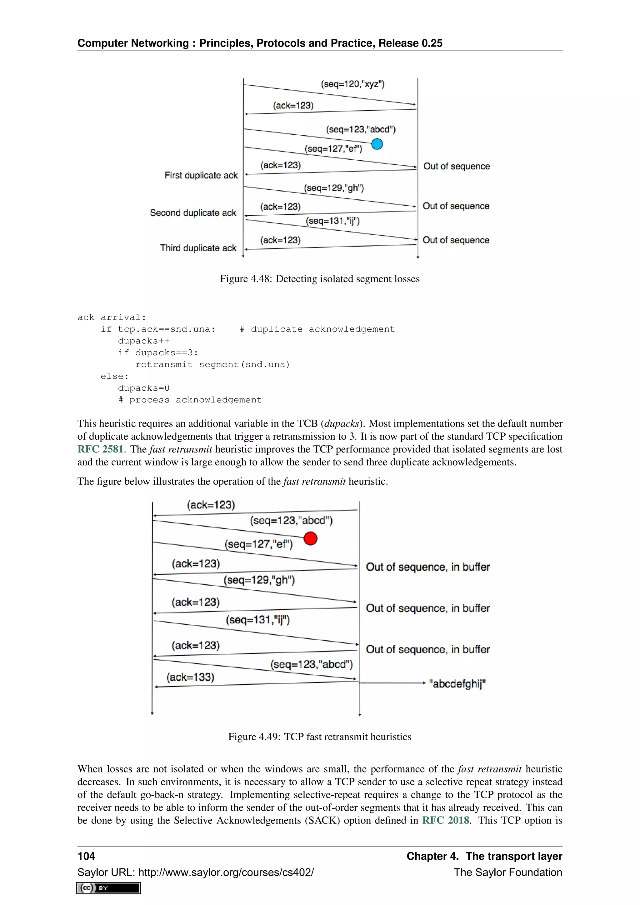
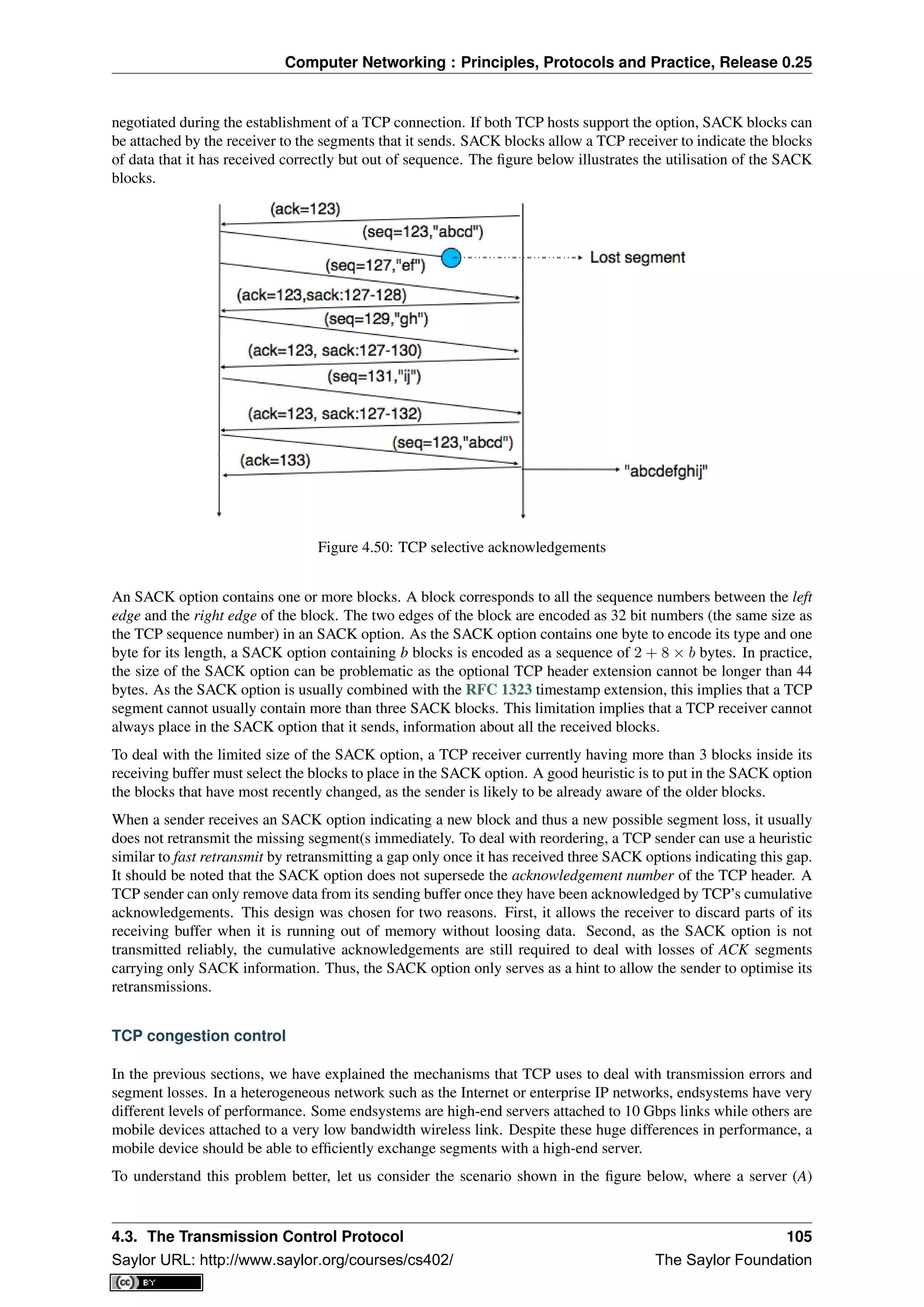
![Computer Networking : Principles, Protocols and Practice, Release 0.25
attached to a 10 Mbps link is sending TCP segments to another computer (C) through a path that contains a 2
Mbps link.
Figure 4.51: TCP over heterogeneous links
In this network, the TCP segments sent by the server reach router R1. R1 forwards the segments towards router R2.
Router R2 can potentially receive segments at 10 Mbps, but it can only forward them at 2 Mbps to router R2 and
then to host C. Router R2 contains buffers that allow it to store the packets that cannot immediately be forwarded
to their destination. To understand the operation of TCP in this environment, let us consider a simplified model of
this network where host A is attached to a 10 Mbps link to a queue that represents the buffers of router R2. This
queue is emptied at a rate of 2 Mbps.
Figure 4.52: TCP self clocking
Let us consider that host A uses a window of three segments. It thus sends three back-to-back segments at 10
Mbps and then waits for an acknowledgement. Host A stops sending segments when its window is full. These
segments reach the buffers of router R2. The first segment stored in this buffer is sent by router R2 at a rate of 2
Mbps to the destination host. Upon reception of this segment, the destination sends an acknowledgement. This
acknowledgement allows host A to transmit a new segment. This segment is stored in the buffers of router R2
while it is transmitting the second segment that was sent by host A... Thus, after the transmission of the first
window of segments, TCP sends one data segment after the reception of each acknowledgement returned by the
destination 24
. In practice, the acknowledgements sent by the destination serve as a kind of clock that allows
the sending host to adapt its transmission rate to the rate at which segments are received by the destination. This
TCP self-clocking is the first mechanism that allows TCP to adapt to heterogeneous networks [Jacobson1988]. It
depends on the availability of buffers to store the segments that have been sent by the sender but have not yet been
transmitted to the destination.
However, TCP is not always used in this environment. In the global Internet, TCP is used in networks where a
large number of hosts send segments to a large number of receivers. For example, let us consider the network
24 If the destination is using delayed acknowledgements, the sending host sends two data segments after each acknowledgement.
106 Chapter 4. The transport layer
Saylor URL: http://www.saylor.org/courses/cs402/ The Saylor Foundation](https://image.slidesharecdn.com/computer-networking-principles-bonaventure-1-30-31-otc1-150825141809-lva1-app6891/75/Computer-networking-principles-bonaventure-1-30-31-otc1-110-2048.jpg)
![Computer Networking : Principles, Protocols and Practice, Release 0.25
depicted below which is similar to the one discussed in [Jacobson1988] and RFC 896. In this network, we assume
that the buffers of the router are infinite to ensure that no packet is lost.
Figure 4.53: The congestion collapse problem
If many TCP senders are attached to the left part of the network above, they all send a window full of segments.
These segments are stored in the buffers of the router before being transmitted towards their destination. If there
are many senders on the left part of the network, the occupancy of the buffers quickly grows. A consequence of
the buffer occupancy is that the round-trip-time, measured by TCP, between the sender and the receiver increases.
Consider a network where 10,000 bits segments are sent. When the buffer is empty, such a segment requires 1
millisecond to be transmitted on the 10 Mbps link and 5 milliseconds to be the transmitted on the 2 Mbps link.
Thus, the round-trip-time measured by TCP is roughly 6 milliseconds if we ignore the propagation delay on the
links. Most routers manage their buffers as a FIFO queue 25
. If the buffer contains 100 segments, the round-trip-
time becomes 1 + 100 × 5 + 5 milliseconds as new segments are only transmitted on the 2 Mbps link once all
previous segments have been transmitted. Unfortunately, TCP uses a retransmission timer and performs go-back-n
to recover from transmission errors. If the buffer occupancy is high, TCP assumes that some segments have been
lost and retransmits a full window of segments. This increases the occupancy of the buffer and the delay through
the buffer... Furthermore, the buffer may store and send on the low bandwidth links several retransmissions of
the same segment. This problem is called congestion collapse. It occurred several times in the late 1980s. For
example, [Jacobson1988] notes that in 1986, the usable bandwidth of a 32 Kbits link dropped to 40 bits per second
due to congestion collapse 26
!
The congestion collapse is a problem that all heterogeneous networks face. Different mechanisms have been
proposed in the scientific literature to avoid or control network congestion. Some of them have been implemented
and deployed in real networks. To understand this problem in more detail, let us first consider a simple network
with two hosts attached to a high bandwidth link that are sending segments to destination C attached to a low
bandwidth link as depicted below.
Figure 4.54: The congestion problem
To avoid congestion collapse, the hosts must regulate their transmission rate 27
by using a congestion control
mechanism. Such a mechanism can be implemented in the transport layer or in the network layer. In TCP/IP
networks, it is implemented in the transport layer, but other technologies such as Asynchronous Transfer Mode
(ATM) or Frame Relay include congestion control mechanisms in lower layers.
Let us first consider the simple problem of a set of i hosts that share a single bottleneck link as shown in the
example above. In this network, the congestion control scheme must achieve the following objectives [CJ1989] :
25 We discuss in another chapter other possible organisations of the router’s buffers.
26 At this time, TCP implementations were mainly following RFC 791. The round-trip-time estimations and the retransmission mechanisms
were very simple. TCP was improved after the publication of [Jacobson1988]
27 In this section, we focus on congestion control mechanisms that regulate the transmission rate of the hosts. Other types of mecha-
nisms have been proposed in the literature. For example, credit-based flow-control has been proposed to avoid congestion in ATM networks
[KR1995]. With a credit-based mechanism, hosts can only send packets once they have received credits from the routers and the credits depend
on the occupancy of the router’s buffers.
4.3. The Transmission Control Protocol 107
Saylor URL: http://www.saylor.org/courses/cs402/ The Saylor Foundation](https://image.slidesharecdn.com/computer-networking-principles-bonaventure-1-30-31-otc1-150825141809-lva1-app6891/75/Computer-networking-principles-bonaventure-1-30-31-otc1-111-2048.jpg)
![Computer Networking : Principles, Protocols and Practice, Release 0.25
1. The congestion control scheme must avoid congestion. In practice, this means that the bottle-
neck link cannot be overloaded. If ri(t) is the transmission rate allocated to host i at time t and
R the bandwidth of the bottleneck link, then the congestion control scheme should ensure that,
on average, ∀t ri(t) ≤ R.
2. The congestion control scheme must be efficient. The bottleneck link is usually both a shared
and an expensive resource. Usually, bottleneck links are wide area links that are much more
expensive to upgrade than the local area networks. The congestion control scheme should ensure
that such links are efficiently used. Mathematically, the control scheme should ensure that
∀t ri(t) ≈ R.
3. The congestion control scheme should be fair. Most congestion schemes aim at achieving max-
min fairness. An allocation of transmission rates to sources is said to be max-min fair if :
• no link in the network is congested
• the rate allocated to source j cannot be increased without decreasing the rate allocated to a
source i whose allocation is smaller than the rate allocated to source j [Leboudec2008] .
Depending on the network, a max-min fair allocation may not always exist. In practice, max-min fairness is an
ideal objective that cannot necessarily be achieved. When there is a single bottleneck link as in the example above,
max-min fairness implies that each source should be allocated the same transmission rate.
To visualise the different rate allocations, it is useful to consider the graph shown below. In this graph, we plot
on the x-axis (resp. y-axis) the rate allocated to host B (resp. A). A point in the graph (rB, rA) corresponds to a
possible allocation of the transmission rates. Since there is a 2 Mbps bottleneck link in this network, the graph
can be divided into two regions. The lower left part of the graph contains all allocations (rB, rA) such that the
bottleneck link is not congested (rA + rB < 2). The right border of this region is the efficiency line, i.e. the set
of allocations that completely utilise the bottleneck link (rA + rB = 2). Finally, the fairness line is the set of fair
allocations.
Figure 4.55: Possible allocated transmission rates
As shown in the graph above, a rate allocation may be fair but not efficient (e.g. rA = 0.7, rB = 0.7), fair and
efficient ( e.g. rA = 1, rB = 1) or efficient but not fair (e.g. rA = 1.5, rB = 0.5). Ideally, the allocation should
be both fair and efficient. Unfortunately, maintaining such an allocation with fluctuations in the number of flows
that use the network is a challenging problem. Furthermore, there might be several thousands of TCP connections
or more that pass through the same link 28
.
To deal with these fluctuations in demand, which result in fluctuations in the available bandwidth, computer
networks use a congestion control scheme. This congestion control scheme should achieve the three objectives
listed above. Some congestion control schemes rely on a close cooperation between the endhosts and the routers,
while others are mainly implemented on the endhosts with limited support from the routers.
28 For example, the measurements performed in the Sprint network in 2004 reported more than 10k active TCP connections on a link, see
https://research.sprintlabs.com/packstat/packetoverview.php. More recent information about backbone links may be obtained from caida ‘s
realtime measurements, see e.g. http://www.caida.org/data/realtime/passive/
108 Chapter 4. The transport layer
Saylor URL: http://www.saylor.org/courses/cs402/ The Saylor Foundation](https://image.slidesharecdn.com/computer-networking-principles-bonaventure-1-30-31-otc1-150825141809-lva1-app6891/75/Computer-networking-principles-bonaventure-1-30-31-otc1-112-2048.jpg)
![Computer Networking : Principles, Protocols and Practice, Release 0.25
A congestion control scheme can be modelled as an algorithm that adapts the transmission rate (ri(t)) of host i
based on the feedback received from the network. Different types of feedbacks are possible. The simplest scheme
is a binary feedback [CJ1989] [Jacobson1988] where the hosts simply learn whether the network is congested or
not. Some congestion control schemes allow the network to regularly send an allocated transmission rate in Mbps
to each host [BF1995].
Let us focus on the binary feedback scheme which is the most widely used today. Intuitively, the congestion
control scheme should decrease the transmission rate of a host when congestion has been detected in the network,
in order to avoid congestion collapse. Furthermore, the hosts should increase their transmission rate when the
network is not congested. Otherwise, the hosts would not be able to efficiently utilise the network. The rate
allocated to each host fluctuates with time, depending on the feedback received from the network. The figure
below illustrates the evolution of the transmission rates allocated to two hosts in our simple network. Initially, two
hosts have a low allocation, but this is not efficient. The allocations increase until the network becomes congested.
At this point, the hosts decrease their transmission rate to avoid congestion collapse. If the congestion control
scheme works well, after some time the allocations should become both fair and efficient.
Figure 4.56: Evolution of the transmission rates
Various types of rate adaption algorithms are possible. Dah Ming Chiu and Raj Jain have analysed, in [CJ1989],
different types of algorithms that can be used by a source to adapt its transmission rate to the feedback received
from the network. Intuitively, such a rate adaptation algorithm increases the transmission rate when the network
is not congested (ensure that the network is efficiently used) and decrease the transmission rate when the network
is congested (to avoid congestion collapse).
The simplest form of feedback that the network can send to a source is a binary feedback (the network is congested
or not congested). In this case, a linear rate adaptation algorithm can be expressed as :
• rate(t + 1) = αC + βCrate(t) when the network is congested
• rate(t + 1) = αN + βN rate(t) when the network is not congested
With a linear adaption algorithm, αC, αN , βC and βN are constants. The analysis of [CJ1989] shows that to
be fair and efficient, such a binary rate adaption mechanism must rely on Additive Increase and Multiplicative
Decrease. When the network is not congested, the hosts should slowly increase their transmission rate (βN =
1 and αN > 0). When the network is congested, the hosts must multiplicatively decrease their transmission rate
(βC < 1 and αC = 0). Such an AIMD rate adaptation algorithm can be implemented by the pseudo-code below
# Additive Increase Multiplicative Decrease
if congestion :
rate=rate*betaC # multiplicative decrease, betaC<1
else
rate=rate+alphaN # additive increase, v0>0
Note: Which binary feedback ?
Two types of binary feedback are possible in computer networks. A first solution is to rely on implicit feedback.
This is the solution chosen for TCP. TCP’s congestion control scheme [Jacobson1988] does not require any coop-
eration from the router. It only assumes that they use buffers and that they discard packets when there is congestion.
4.3. The Transmission Control Protocol 109
Saylor URL: http://www.saylor.org/courses/cs402/ The Saylor Foundation](https://image.slidesharecdn.com/computer-networking-principles-bonaventure-1-30-31-otc1-150825141809-lva1-app6891/75/Computer-networking-principles-bonaventure-1-30-31-otc1-113-2048.jpg)
![Computer Networking : Principles, Protocols and Practice, Release 0.25
TCP uses the segment losses as an indication of congestion. When there are no losses, the network is assumed to
be not congested. This implies that congestion is the main cause of packet losses. This is true in wired networks,
but unfortunately not always true in wireless networks. Another solution is to rely on explicit feedback. This
is the solution proposed in the DECBit congestion control scheme [RJ1995] and used in Frame Relay and ATM
networks. This explicit feedback can be implemented in two ways. A first solution would be to define a special
message that could be sent by routers to hosts when they are congested. Unfortunately, generating such messages
may increase the amount of congestion in the network. Such a congestion indication packet is thus discouraged
RFC 1812. A better approach is to allow the intermediate routers to indicate, in the packets that they forward,
their current congestion status. Binary feedback can be encoded by using one bit in the packet header. With such a
scheme, congested routers set a special bit in the packets that they forward while non-congested routers leave this
bit unmodified. The destination host returns the congestion status of the network in the acknowledgements that it
sends. Details about such a solution in IP networks may be found in RFC 3168. Unfortunately, as of this writing,
this solution is still not deployed despite its potential benefits.
The TCP congestion control scheme was initially proposed by Van Jacobson in [Jacobson1988]. The current
specification may be found in RFC 5681. TCP relies on Additive Increase and Multiplicative Decrease (AIMD).
To implement AIMD, a TCP host must be able to control its transmission rate. A first approach would be to use
timers and adjust their expiration times in function of the rate imposed by AIMD. Unfortunately, maintaining such
timers for a large number of TCP connections can be difficult. Instead, Van Jacobson noted that the rate of TCP
congestion can be artificially controlled by constraining its sending window. A TCP connection cannot send data
faster than window
rtt where window is the maximum between the host’s sending window and the window advertised
by the receiver.
TCP’s congestion control scheme is based on a congestion window. The current value of the congestion window
(cwnd) is stored in the TCB of each TCP connection and the window that can be used by the sender is constrained
by min(cwnd, rwin, swin) where swin is the current sending window and rwin the last received receive win-
dow. The Additive Increase part of the TCP congestion control increments the congestion window by MSS bytes
every round-trip-time. In the TCP literature, this phase is often called the congestion avoidance phase. The Mul-
tiplicative Decrease part of the TCP congestion control divides the current value of the congestion window once
congestion has been detected.
When a TCP connection begins, the sending host does not know whether the part of the network that it uses
to reach the destination is congested or not. To avoid causing too much congestion, it must start with a small
congestion window. [Jacobson1988] recommends an initial window of MSS bytes. As the additive increase part
of the TCP congestion control scheme increments the congestion window by MSS bytes every round-trip-time,
the TCP connection may have to wait many round-trip-times before being able to efficiently use the available
bandwidth. This is especially important in environments where the bandwidth × rtt product is high. To avoid
waiting too many round-trip-times before reaching a congestion window that is large enough to efficiently utilise
the network, the TCP congestion control scheme includes the slow-start algorithm. The objective of the TCP
slow-start is to quickly reach an acceptable value for the cwnd. During slow-start, the congestion window is
doubled every round-trip-time. The slow-start algorithm uses an additional variable in the TCB : sshtresh (slow-
start threshold). The ssthresh is an estimation of the last value of the cwnd that did not cause congestion. It is
initialised at the sending window and is updated after each congestion event.
In practice, a TCP implementation considers the network to be congested once its needs to retransmit a segment.
The TCP congestion control scheme distinguishes between two types of congestion :
• mild congestion. TCP considers that the network is lightly congested if it receives three duplicate acknowl-
edgements and performs a fast retransmit. If the fast retransmit is successful, this implies that only one
segment has been lost. In this case, TCP performs multiplicative decrease and the congestion window is
divided by 2. The slow-start threshold is set to the new value of the congestion window.
• severe congestion. TCP considers that the network is severely congested when its retransmission timer
expires. In this case, TCP retransmits the first segment, sets the slow-start threshold to 50% of the congestion
window. The congestion window is reset to its initial value and TCP performs a slow-start.
The figure below illustrates the evolution of the congestion window when there is severe congestion. At the
beginning of the connection, the sender performs slow-start until the first segments are lost and the retransmission
timer expires. At this time, the ssthresh is set to half of the current congestion window and the congestion window
is reset at one segment. The lost segments are retransmitted as the sender again performs slow-start until the
110 Chapter 4. The transport layer
Saylor URL: http://www.saylor.org/courses/cs402/ The Saylor Foundation](https://image.slidesharecdn.com/computer-networking-principles-bonaventure-1-30-31-otc1-150825141809-lva1-app6891/75/Computer-networking-principles-bonaventure-1-30-31-otc1-114-2048.jpg)
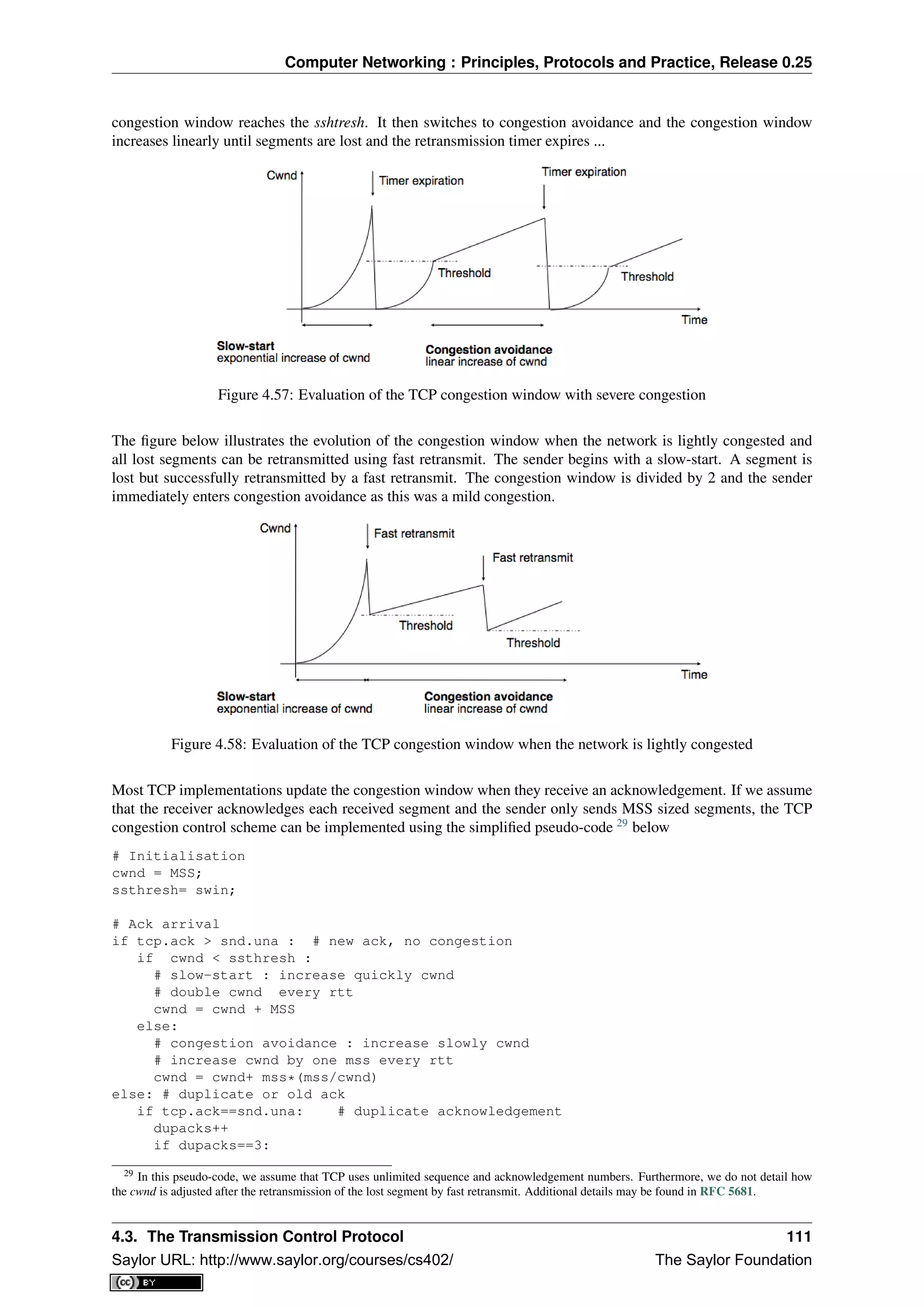
![Computer Networking : Principles, Protocols and Practice, Release 0.25
retransmitsegment(snd.una)
ssthresh=max(cwnd/2,2*MSS)
cwnd=ssthresh
else:
dupacks=0
# ack for old segment, ignored
Expiration of the retransmission timer:
send(snd.una) # retransmit first lost segment
sshtresh=max(cwnd/2,2*MSS)
cwnd=MSS
Furthermore when a TCP connection has been idle for more than its current retransmission timer, it should reset its
congestion window to the congestion window size that it uses when the connection begins, as it no longer knows
the current congestion state of the network.
Note: Initial congestion window
The original TCP congestion control mechanism proposed in [Jacobson1988] recommended that each TCP con-
nection should begin by setting cwnd = MSS. However, in today’s higher bandwidth networks, using such a
small initial congestion window severely affects the performance for short TCP connections, such as those used
by web servers. Since the publication of RFC 3390, TCP hosts are allowed to use an initial congestion window
of about 4 KBytes, which corresponds to 3 segments in many environments.
Thanks to its congestion control scheme, TCP adapts its transmission rate to the losses that occur in the net-
work. Intuitively, the TCP transmission rate decreases when the percentage of losses increases. Researchers have
proposed detailed models that allow the prediction of the throughput of a TCP connection when losses occur
[MSMO1997] . To have some intuition about the factors that affect the performance of TCP, let us consider a
very simple model. Its assumptions are not completely realistic, but it gives us good intuition without requiring
complex mathematics.
This model considers a hypothetical TCP connection that suffers from equally spaced segment losses. If p is the
segment loss ratio, then the TCP connection successfully transfers 1
p − 1 segments and the next segment is lost.
If we ignore the slow-start at the beginning of the connection, TCP in this environment is always in congestion
avoidance as there are only isolated losses that can be recovered by using fast retransmit. The evolution of the
congestion window is thus as shown in the figure below. Note the that x-axis of this figure represents time measured
in units of one round-trip-time, which is supposed to be constant in the model, and the y-axis represents the size
of the congestion window measured in MSS-sized segments.
Figure 4.59: Evolution of the congestion window with regular losses
As the losses are equally spaced, the congestion window always starts at some value (W
2 ), and is incremented by
one MSS every round-trip-time until it reaches twice this value (W). At this point, a segment is retransmitted and
the cycle starts again. If the congestion window is measured in MSS-sized segments, a cycle lasts W
2 round-trip-
times. The bandwidth of the TCP connection is the number of bytes that have been transmitted during a given
period of time. During a cycle, the number of segments that are sent on the TCP connection is equal to the area of
the yellow trapeze in the figure. Its area is thus :
area = (W
2 )2
+ 1
2 × (W
2 )2
= 3×W 2
8
112 Chapter 4. The transport layer
Saylor URL: http://www.saylor.org/courses/cs402/ The Saylor Foundation](https://image.slidesharecdn.com/computer-networking-principles-bonaventure-1-30-31-otc1-150825141809-lva1-app6891/75/Computer-networking-principles-bonaventure-1-30-31-otc1-116-2048.jpg)
![Computer Networking : Principles, Protocols and Practice, Release 0.25
However, given the regular losses that we consider, the number of segments that are sent between two losses (i.e.
during a cycle) is by definition equal to 1
p . Thus, W = 8
3×p = k√
p . The throughput (in bytes per second) of the
TCP connection is equal to the number of segments transmitted divided by the duration of the cycle :
Throughput = area×MSS
time =
3×W 2
8
W
2 ×rtt
or, after having eliminated W, Throughput = 3
2 × MSS
rtt×
√
p
More detailed models and the analysis of simulations have shown that a first order model of the TCP throughput
when losses occur was Throughput ≈ k×MSS
rtt×
√
p . This is an important result which shows that :
• TCP connections with a small round-trip-time can achieve a higher throughput than TCP connections having
a longer round-trip-time when losses occur. This implies that the TCP congestion control scheme is not
completely fair since it favors the connections that have the shorter round-trip-time
• TCP connections that use a large MSS can achieve a higher throughput that the TCP connections that use
a shorter MSS. This creates another source of unfairness between TCP connections. However, it should be
noted that today most hosts are using almost the same MSS, roughly 1460 bytes.
In general, the maximum throughput that can be achieved by a TCP connection depends on its maximum window
size and the round-trip-time if there are no losses. If there are losses, it depends on the MSS, the round-trip-time
and the loss ratio.
Throughput < min(window
rtt , k×MSS
rtt×
√
p )
Note: The TCP congestion control zoo
The first TCP congestion control scheme was proposed by Van Jacobson in [Jacobson1988]. In addition to writing
the scientific paper, Van Jacobson also implemented the slow-start and congestion avoidance schemes in release
4.3 Tahoe of the BSD Unix distributed by the University of Berkeley. Later, he improved the congestion control
by adding the fast retransmit and the fast recovery mechanisms in the Reno release of 4.3 BSD Unix. Since
then, many researchers have proposed, simulated and implemented modifications to the TCP congestion control
scheme. Some of these modifications are still used today, e.g. :
• NewReno ( RFC 3782), which was proposed as an improvement of the fast recovery mechanism in the Reno
implementation
• TCP Vegas, which uses changes in the round-trip-time to estimate congestion in order to avoid it [BOP1994]
• CUBIC, which was designed for high bandwidth links and is the default congestion control scheme in the
Linux 2.6.19 kernel [HRX2008]
• Compound TCP, which was designed for high bandwidth links is the default congestion control scheme in
several Microsoft operating systems [STBT2009]
A search of the scientific literature will probably reveal more than 100 different variants of the TCP congestion
control scheme. Most of them have only been evaluated by simulations. However, the TCP implementation in
the recent Linux kernels supports several congestion control schemes and new ones can be easily added. We can
expect that new TCP congestion control schemes will always continue to appear.
4.4 Summary
In this chapter, we have studied the transport layer. This layer provides two types of services to the application
layer. The unreliable connectionless service is the simplest service offered to applications. On the Internet, this is
the service offered by UDP. However, most applications prefer to use a reliable and connection-oriented transport
service. We have shown that providing this service was much more complex than providing an unreliable service
as the transport layer needs to recover from the errors that occur in the network layer. For this, transport layer
protocols rely on several mechanisms. First, they use a handshake mechanism, such as the three-way handshake
mechanism, to correctly establish a transport connection. Once the connection has been established, transport
entities exchange segments. Each segment contains a sequence number, and the transport layer uses acknowl-
edgements to confirm the segments that have been correctly received. In addition, timers are used to recover from
segment losses and sliding windows are used to avoid overflowing the buffers of the transport entities. Finally,
4.4. Summary 113
Saylor URL: http://www.saylor.org/courses/cs402/ The Saylor Foundation](https://image.slidesharecdn.com/computer-networking-principles-bonaventure-1-30-31-otc1-150825141809-lva1-app6891/75/Computer-networking-principles-bonaventure-1-30-31-otc1-117-2048.jpg)
![Computer Networking : Principles, Protocols and Practice, Release 0.25
we explained how a transport connection can be safely released. We then discussed the mechanisms that are used
in TCP, the reliable transport protocol, used by most applications on the Internet. Most notably, we described the
congestion control mechanism that has been included in TCP since the late 1980s and explained how the reliability
mechanisms used by TCP have been tuned over the years.
4.5 Exercises
This section is divided in two parts. The first part contains exercises on the principles of transport protocols,
including TCP. The second part contains programming challenges packet analysis tools to observe the behaviour
of transport protocols.
4.5.1 Principles
1. Consider the Alternating Bit Protocol as described in this chapter
• How does the protocol recover from the loss of a data segment ?
• How does the protocol recovers from the loss of an acknowledgement ?
2. A student proposed to optimise the Alternating Bit Protocol by adding a negative acknowledgment, i.e. the
receiver sends a NAK control segment when it receives a corrupted data segment. What kind of information
should be placed in this control segment and how should the sender react when receiving such a NAK ?
3. Transport protocols rely on different types of checksums to verify whether segments have been affected by
transmission errors. The most frequently used checksums are :
• the Internet checksum used by UDP, TCP and other Internet protocols
which is defined in RFC 1071 and implemented in various modules, e.g.
http://ilab.cs.byu.edu/cs460/code/ftp/ichecksum.py for a python implementation
• the 16 bits or the 32 bits Cyclical Redundancy Checks (CRC) that are often used on disks, in
zip archives and in datalink layer protocols. See http://docs.python.org/library/binascii.html for
a python module that contains the 32 bits CRC
• the Alder checksum defined in RFC 2920 for the SCTP protocol but replaced by a CRC later
RFC 3309
• the Fletcher checksum [Fletcher1982], see http://drdobbs.com/database/184408761 for imple-
mentation details
By using your knowledge of the Internet checksum, can you find a transmission error that will not be
detected by the Internet checksum ?
4. The CRCs are efficient error detection codes that are able to detect :
• all errors that affect an odd number of bits
• all errors that affect a sequence of bits which is shorter than the length of the CRC
Carry experiments with one implementation of CRC-32 to verify that this is indeed the case.
5. Checksums and CRCs should not be confused with secure hash functions such as MD5 defined in RFC
1321 or SHA-1 described in RFC 4634. Secure hash functions are used to ensure that files or sometimes
packets/segments have not been modified. Secure hash functions aim at detecting malicious changes while
checksums and CRCs only detect random transmission errors. Perform some experiments with hash func-
tions such as those defined in the http://docs.python.org/library/hashlib.html python hashlib module to verify
that this is indeed the case.
6. A version of the Alternating Bit Protocol supporting variable length segments uses a header that contains
the following fields :
• a number (0 or 1)
• a length field that indicates the length of the data
114 Chapter 4. The transport layer
Saylor URL: http://www.saylor.org/courses/cs402/ The Saylor Foundation](https://image.slidesharecdn.com/computer-networking-principles-bonaventure-1-30-31-otc1-150825141809-lva1-app6891/75/Computer-networking-principles-bonaventure-1-30-31-otc1-118-2048.jpg)
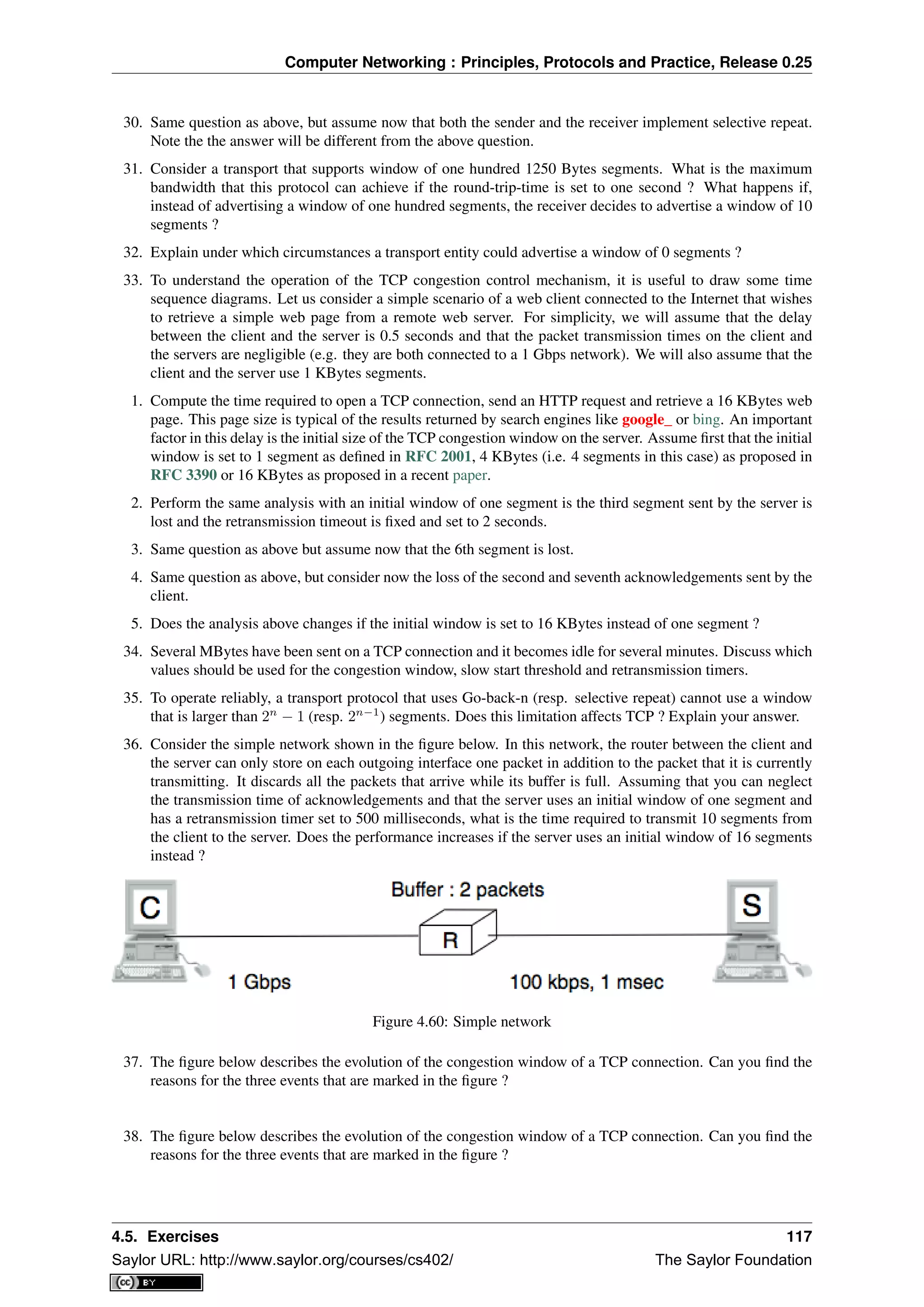
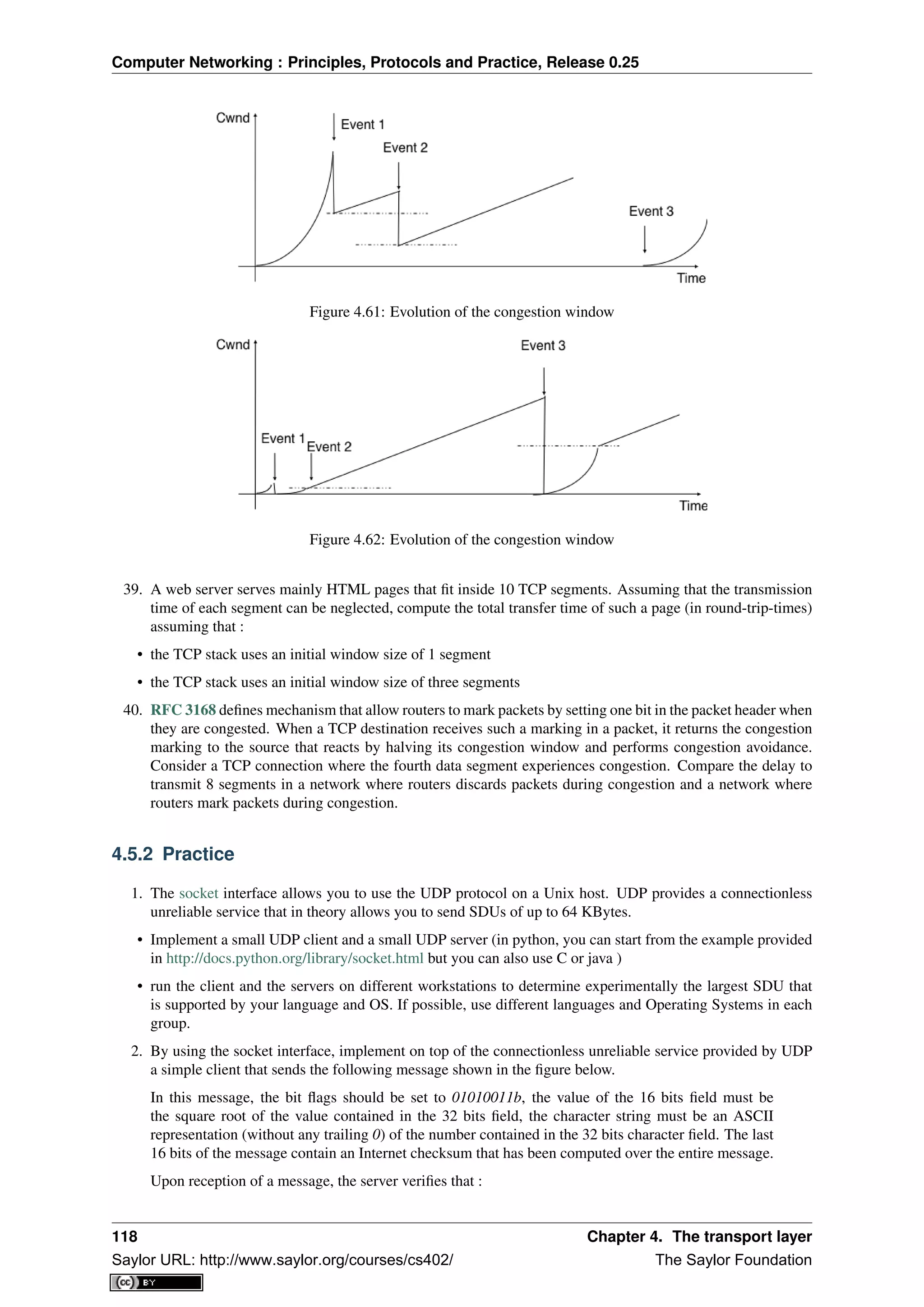
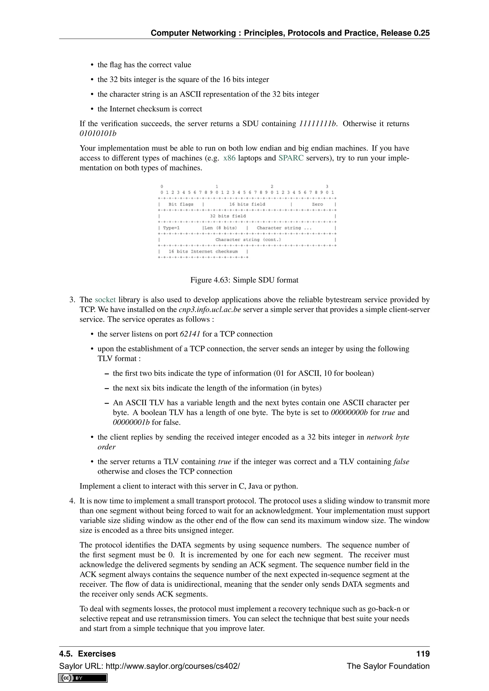
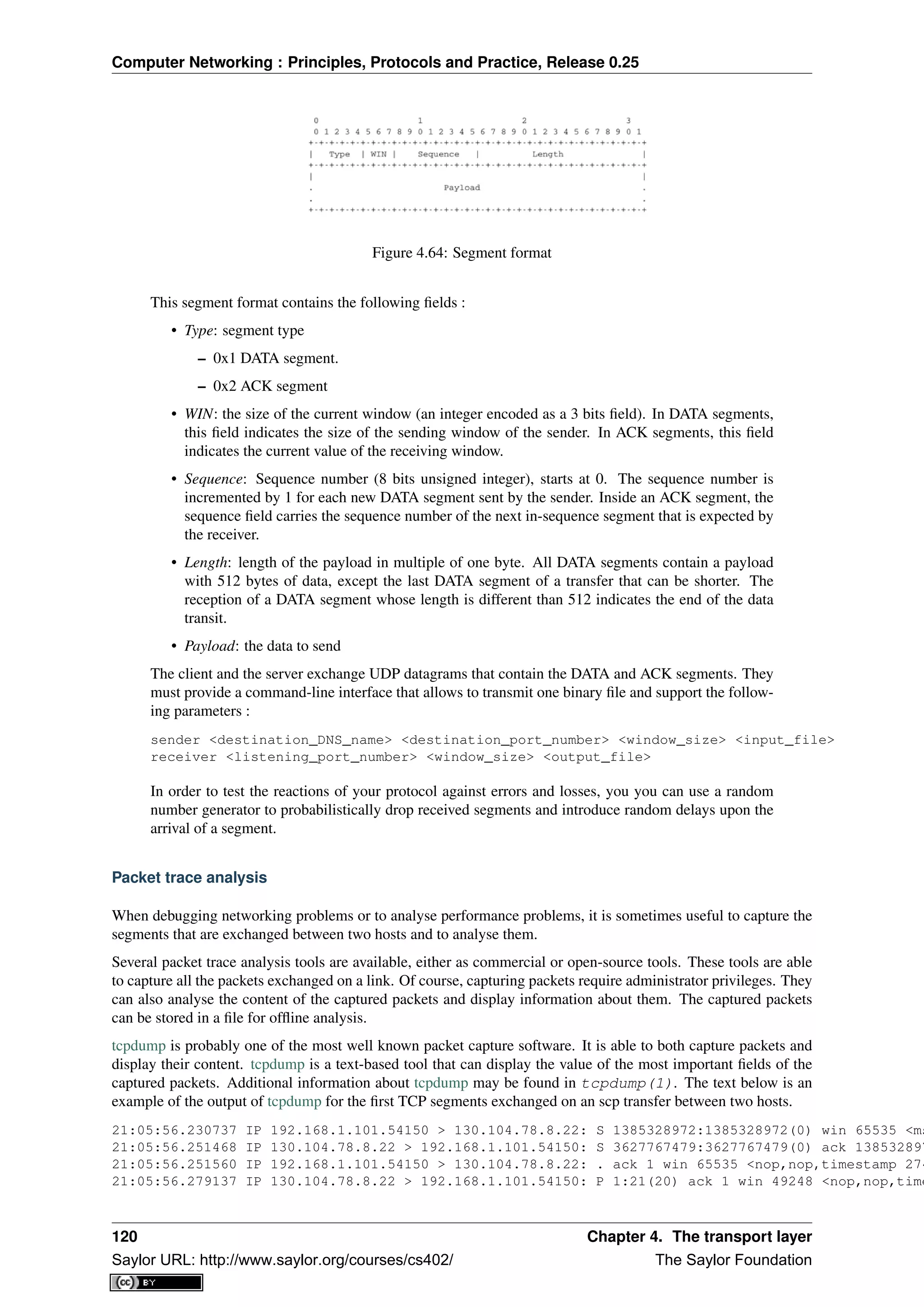
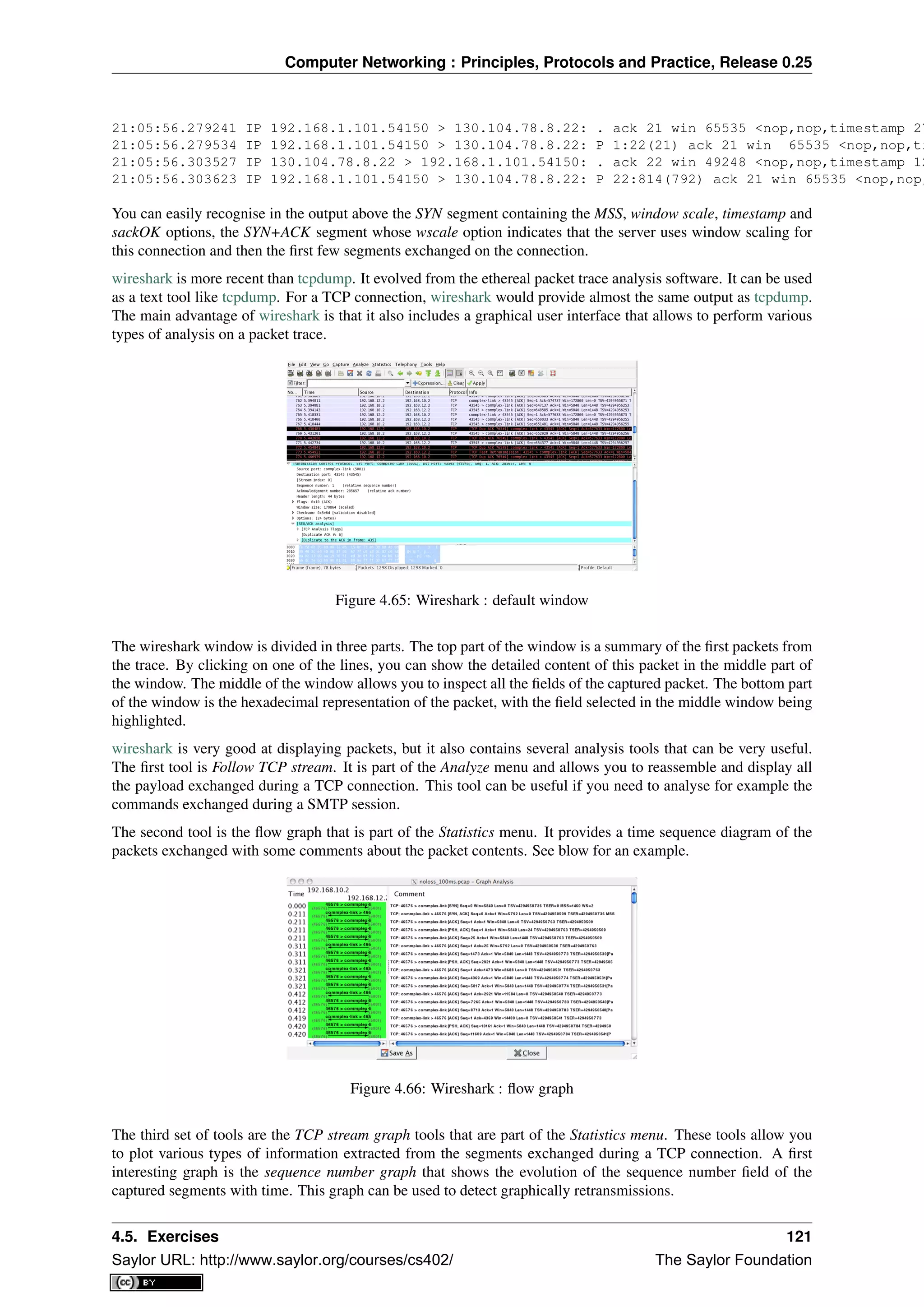
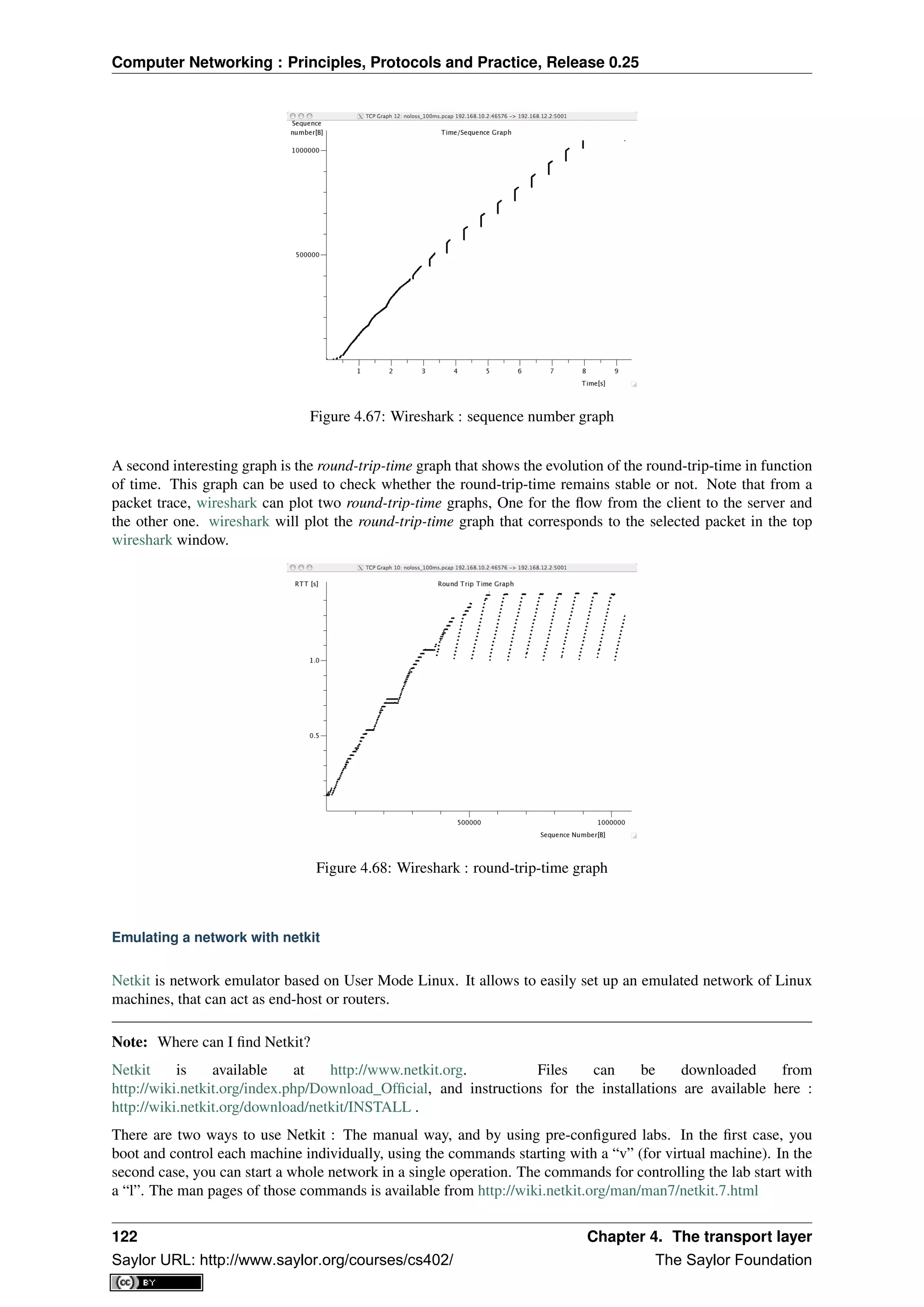
![Computer Networking : Principles, Protocols and Practice, Release 0.25
You must be careful not to forgot to stop your virtual machines and labs, using either vhalt or lhalt.
A netkit lab is simply a directory containing at least a configuration file called lab.conf, and one directory for each
virtual machine. In the case the lab available on iCampus, the network is composed of two pcs, pc1 and pc2, both
of them being connected to a router r1. The lab.conf file contains the following lines :
pc1[0]=A
pc2[0]=B
r1[0]=A
r1[1]=B
This means that pc1 and r1 are connected to a “virtual LAN” named A via their interface eth0, while pc2 and r1
are connected to the “virtual LAN” B via respectively their interfaces eth0 and eth1.
The directory of each device is initially empty, but will be used by Netkit to store their filesystem.
The lab directory can contain optional files. In the lab provided to you, the “pc1.startup” file contains the shell
instructions to be executed on startup of the virtual machine. In this specific case, the script configures the interface
eth0 to allow traffic exchanges between pc1 and r1, as well as the routing table entry to join pc2.
Starting a lab consists thus simply in unpacking the provided archive, going into the lab directory and typing lstart
to start the network.
Note: File sharing between virtual machines and host
Virtual machines can access to the directory of the lab they belong to. This repertory is mounted in their filesystem
at the path /hostlab.
In the netkit lab (exercises/netkit/netkit_lab_2hosts_1rtr_ipv4.tar.tar.gz, you can find
a simple python client/server application that establishes TCP connections. Feel free to re-use this code to perform
your analysis.
Note: netkit tools
As the virtual machines run Linux, standard networking tools such as hping, tcpdump, netstat etc. are available as
usual.
Note that capturing network traces can be facilitated by using the uml_dump extension available at
http://kartoch.msi.unilim.fr/blog/?p=19 . This extension is already installed in the Netkit installation on the stu-
dent lab. In order to capture the traffic exchanged on a given ‘virtual LAN’, you simply need to issue the command
vdump <LAN name> on the host. If you want to pipe the trace to wireshark, you can use vdump A | wireshark -i -
-k
1. A TCP/IP stack receives a SYN segment with the sequence number set to 1234. What will be the value of
the acknowledgement number in the returned SYN+ACK segment ?
2. Is it possible for a TCP/IP stack to return a SYN+ACK segment with the acknowledgement number set to 0
? If no, explain why. If yes, what was the content of the received SYN segment.
3. Open the tcpdump packet trace exercises/traces/trace.5connections_opening_closing.pcap
and identify the number of different TCP connections that are established and closed. For each connection,
explain by which mechanism they are closed. Analyse the initial sequence numbers that are used in the
SYN and SYN+ACK segments. How do these initial sequence numbers evolve ? Are they increased every
4 microseconds ?
4. The tcpdump packet trace exercises/traces/trace.5connections.pcap contains several
connection attempts. Can you explain what is happening with these connection attempts ?
5. The tcpdump packet trace exercises/traces/trace.ipv6.google.com.pcap was collected
from a popular website that is accessible by using IPv6. Explain the TCP options that are supported by the
client and the server.
4.5. Exercises 123
Saylor URL: http://www.saylor.org/courses/cs402/ The Saylor Foundation](https://image.slidesharecdn.com/computer-networking-principles-bonaventure-1-30-31-otc1-150825141809-lva1-app6891/75/Computer-networking-principles-bonaventure-1-30-31-otc1-127-2048.jpg)
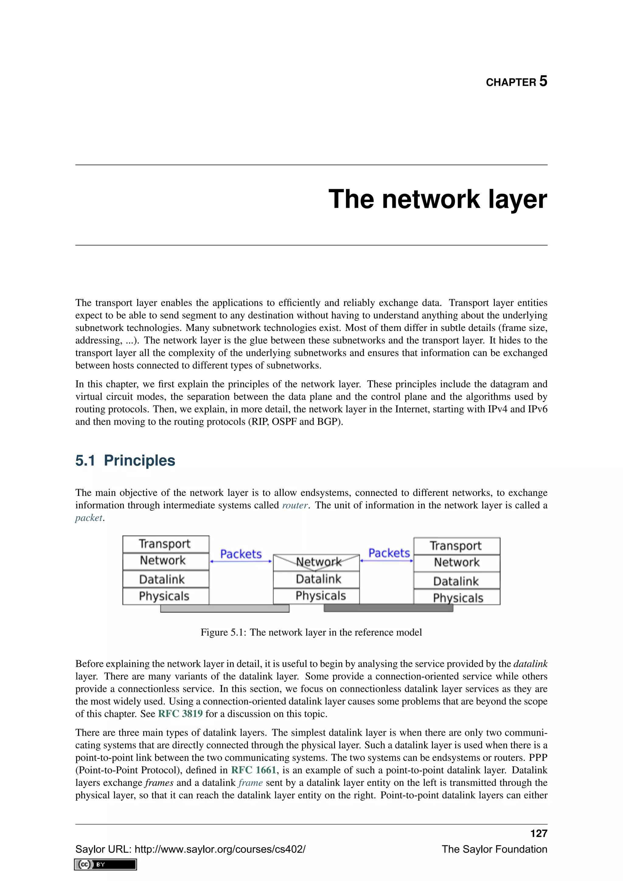
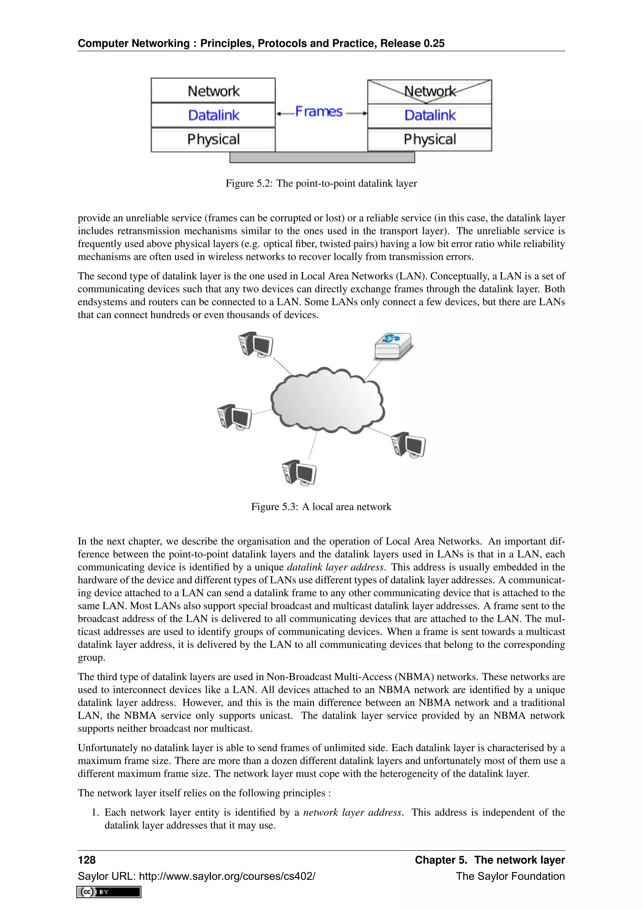
![Computer Networking : Principles, Protocols and Practice, Release 0.25
Figure 5.4: A simple internetwork
In the example above, host A sends its packet to router R1. R1 consults its routing table and forwards the packet
towards R2. Based on its own routing table, R2 decides to forward the packet to R5 that can deliver it to its
destination.
To allow hosts to exchange packets, a network relies on two different types of protocols and mechanisms. First,
there must be a precise definition of the format of the packets that are sent by hosts and processed by routers.
Second, the algorithm used by the routers to forward these packets must be defined. This protocol and this
algorithm are part of the data plane of the network layer. The data plane contains all the protocols and algorithms
that are used by hosts and routers to create and process the packets that contain user data.
The data plane, and in particular the forwarding algorithm used by the routers, depends on the routing tables
that are maintained on reach router. These routing tables can be maintained by using various techniques (manual
configuration, distributed protocols, centralised computation, etc). These techniques are part of the control plane
of the network layer. The control plane contains all the protocols and mechanisms that are used to compute and
install routing tables on the routers.
The datagram organisation has been very popular in computer networks. Datagram based network layers include
IPv4 and IPv6 in the global Internet, CLNP defined by the ISO, IPX defined by Novell or XNS defined by Xerox
[Perlman2000].
Virtual circuit organisation
The main advantage of the datagram organisation is its simplicity. The principles of this organisation can easily
be understood. Furthermore, it allows a host to easily send a packet towards any destination at any time. However,
as each packet is forwarded independently by intermediate routers, packets sent by a host may not follow the
same path to reach a given destination. This may cause packet reordering, which may be annoying for transport
protocols. Furthermore, as a router using hop-by-hop forwarding always forwards packets sent towards the same
destination over the same outgoing interface, this may cause congestion over some links.
The second organisation of the network layer, called virtual circuits, has been inspired by the organisation of
telephone networks. Telephone networks have been designed to carry phone calls that usually last a few minutes.
Each phone is identified by a telephone number and is attached to a telephone switch. To initiate a phone call, a
telephone first needs to send the destination’s phone number to its local switch. The switch cooperates with the
other switches in the network to create a bi-directional channel between the two telephones through the network.
This channel will be used by the two telephones during the lifetime of the call and will be released at the end of
the call. Until the 1960s, most of these channels were created manually, by telephone operators, upon request of
the caller. Today’s telephone networks use automated switches and allow several channels to be carried over the
same physical link, but the principles remain roughly the same.
130 Chapter 5. The network layer
Saylor URL: http://www.saylor.org/courses/cs402/ The Saylor Foundation](https://image.slidesharecdn.com/computer-networking-principles-bonaventure-1-30-31-otc1-150825141809-lva1-app6891/75/Computer-networking-principles-bonaventure-1-30-31-otc1-134-2048.jpg)
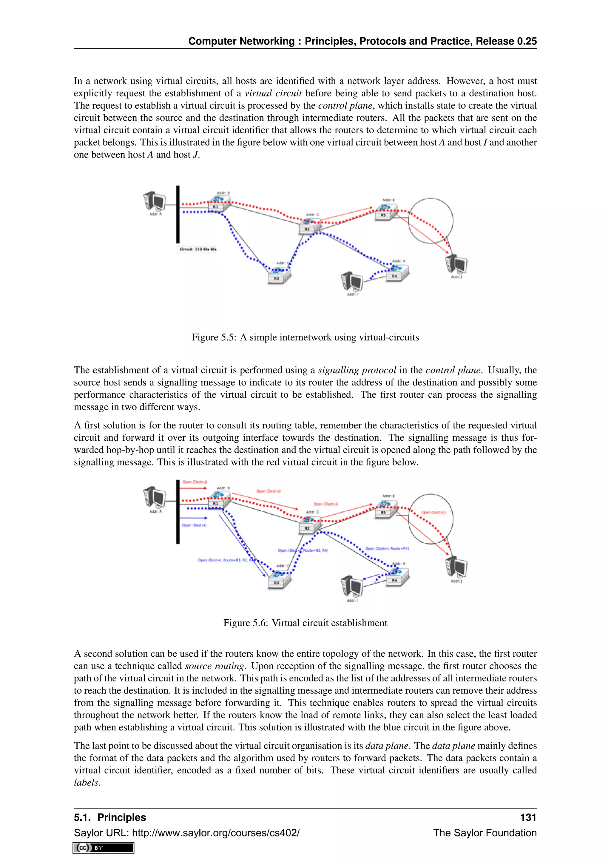
![Computer Networking : Principles, Protocols and Practice, Release 0.25
Each host maintains a flow table that associates a label with each virtual circuit that is has established. When a
router receives a packet containing a label, it extracts the label and consults its label forwarding table. This table
is a data structure that maps each couple (incoming interface, label) to the outgoing interface to be used to forward
the packet as well as the label that must be placed in the outgoing packets. In practice, the label forwarding table
can be implemented as a vector and the couple (incoming interface, label) is the index of the entry in the vector
that contains the outgoing interface and the outgoing label. Thus a single memory access is sufficient to consult
the label forwarding table. The utilisation of the label forwarding table is illustrated in the figure below.
Figure 5.7: Label forwarding tables in a network using virtual circuits
The virtual circuit organisation has been mainly used in public networks, starting from X.25 and then Frame Relay
and Asynchronous Transfer Mode (ATM) network.
Both the datagram and virtual circuit organisations have advantages and drawbacks. The main advantage of
the datagram organisation is that hosts can easily send packets to any number of destinations while the virtual
circuit organisation requires the establishment of a virtual circuit before the transmission of a data packet. This
solution can be costly for hosts that exchange small amounts of data. On the other hand, the main advantage
of the virtual circuit organisation is that the forwarding algorithm used by routers is simpler than when using
the datagram organisation. Furthermore, the utilisation of virtual circuits may allow the load to be better spread
through the network thanks to the utilisation of multiple virtual circuits. The MultiProtocol Label Switching
(MPLS) technique that we will discuss in another revision of this book can be considered as a good compromise
between datagram and virtual circuits. MPLS uses virtual circuits between routers, but does not extend them to
the endhosts. Additional information about MPLS may be found in [ML2011].
5.1.2 The control plane
One of the objectives of the control plane in the network layer is to maintain the routing tables that are used on all
routers. As indicated earlier, a routing table is a data structure that contains, for each destination address (or block
of addresses) known by the router, the outgoing interface over which the router must forward a packet destined to
this address. The routing table may also contain additional information such as the address of the next router on
the path towards the destination or an estimation of the cost of this path.
In this section, we discuss the three main techniques that can be used to maintain the routing tables in a network.
Static routing
The simplest solution is to pre-compute all the routing tables of all routers and to install them on each router.
Several algorithms can be used to compute these tables.
132 Chapter 5. The network layer
Saylor URL: http://www.saylor.org/courses/cs402/ The Saylor Foundation](https://image.slidesharecdn.com/computer-networking-principles-bonaventure-1-30-31-otc1-150825141809-lva1-app6891/75/Computer-networking-principles-bonaventure-1-30-31-otc1-136-2048.jpg)
![Computer Networking : Principles, Protocols and Practice, Release 0.25
A simple solution is to use shortest path routing and to minimise the number of intermediate routers to reach
each destination. More complex algorithms can take into account the expected load on the links to ensure that
congestion does not occur for a given traffic demand. These algorithms must all ensure that :
• all routers are configured with a route to reach each destination
• none of the paths composed with the entries found in the routing tables contain a cycle. Such a cycle would
lead to a forwarding loop.
The figure below shows sample routing tables in a five routers network.
Figure 5.8: Routing tables in a simple network
The main drawback of static routing is that it does not adapt to the evolution of the network. When a new router
or link is added, all routing tables must be recomputed. Furthermore, when a link or router fails, the routing tables
must be updated as well.
Distance vector routing
Distance vector routing is a simple distributed routing protocol. Distance vector routing allows routers to auto-
matically discover the destinations reachable inside the network as well as the shortest path to reach each of these
destinations. The shortest path is computed based on metrics or costs that are associated to each link. We use
l.cost to represent the metric that has been configured for link l on a router.
Each router maintains a routing table. The routing table R can be modelled as a data structure that stores, for each
known destination address d, the following attributes :
• R[d].link is the outgoing link that the router uses to forward packets towards destination d
• R[d].cost is the sum of the metrics of the links that compose the shortest path to reach destination d
• R[d].time is the timestamp of the last distance vector containing destination d
A router that uses distance vector routing regularly sends its distance vector over all its interfaces. The distance
vector is a summary of the router’s routing table that indicates the distance towards each known destination. This
distance vector can be computed from the routing table by using the pseudo-code below.
Every N seconds:
v=Vector()
for d in R[]:
# add destination d to vector
v.add(Pair(d,R[d].cost))
for i in interfaces
# send vector v on this interface
send(v,interface)
When a router boots, it does not know any destination in the network and its routing table only contains itself. It
thus sends to all its neighbours a distance vector that contains only its address at a distance of 0. When a router
receives a distance vector on link l, it processes it as follows.
# V : received Vector
# l : link over which vector is received
def received(V,l):
# received vector from link l
for d in V[]
5.1. Principles 133
Saylor URL: http://www.saylor.org/courses/cs402/ The Saylor Foundation](https://image.slidesharecdn.com/computer-networking-principles-bonaventure-1-30-31-otc1-150825141809-lva1-app6891/75/Computer-networking-principles-bonaventure-1-30-31-otc1-137-2048.jpg)
![Computer Networking : Principles, Protocols and Practice, Release 0.25
if not (d in R[]) :
# new route
R[d].cost=V[d].cost+l.cost
R[d].link=l
R[d].time=now
else :
# existing route, is the new better ?
if ( ((V[d].cost+l.cost) < R[d].cost) or ( R[d].link == l) ) :
# Better route or change to current route
R[d].cost=V[d].cost+l.cost
R[d].link=l
R[d].time=now
The router iterates over all addresses included in the distance vector. If the distance vector contains an address
that the router does not know, it inserts the destination inside its routing table via link l and at a distance which is
the sum between the distance indicated in the distance vector and the cost associated to link l. If the destination
was already known by the router, it only updates the corresponding entry in its routing table if either :
• the cost of the new route is smaller than the cost of the already known route ( (V[d].cost+l.cost) < R[d].cost)
• the new route was learned over the same link as the current best route towards this destination ( R[d].link
== l)
The first condition ensures that the router discovers the shortest path towards each destination. The second condi-
tion is used to take into account the changes of routes that may occur after a link failure or a change of the metric
associated to a link.
To understand the operation of a distance vector protocol, let us consider the network of five routers shown below.
Figure 5.9: Operation of distance vector routing in a simple network
Assume that A is the first to send its distance vector [A=0].
• B and D process the received distance vector and update their routing table with a route towards A.
• D sends its distance vector [D=0,A=1] to A and E. E can now reach A and D.
• C sends its distance vector [C=0] to B and E
• E sends its distance vector [E=0,D=1,A=2,C=2] to D, B and C. B can now reach A, C, D and E
• B sends its distance vector [B=0,A=1,C=1,D=2,E=1] to A, C and E. A, B, C and E can now reach all
destinations.
• A sends its distance vector [A=0,B=1,C=2,D=1,E=2] to B and D.
At this point, all routers can reach all other routers in the network thanks to the routing tables shown in the figure
below.
To deal with link and router failures, routers use the timestamp stored in their routing table. As all routers send
their distance vector every N seconds, the timestamp of each route should be regularly refreshed. Thus no route
should have a timestamp older than N seconds, unless the route is not reachable anymore. In practice, to cope
with the possible loss of a distance vector due to transmission errors, routers check the timestamp of the routes
stored in their routing table every N seconds and remove the routes that are older than 3 × N seconds. When a
router notices that a route towards a destination has expired, it must first associate an ∞ cost to this route and send
134 Chapter 5. The network layer
Saylor URL: http://www.saylor.org/courses/cs402/ The Saylor Foundation](https://image.slidesharecdn.com/computer-networking-principles-bonaventure-1-30-31-otc1-150825141809-lva1-app6891/75/Computer-networking-principles-bonaventure-1-30-31-otc1-138-2048.jpg)
![Computer Networking : Principles, Protocols and Practice, Release 0.25
Figure 5.10: Routing tables computed by distance vector in a simple network
its distance vector to its neighbours to inform them. The route can then be removed from the routing table after
some time (e.g. 3 × N seconds), to ensure that the neighbouring routers have received the bad news, even if some
distance vectors do not reach them due to transmission errors.
Consider the example above and assume that the link between routers A and B fails. Before the failure, A used B
to reach destinations B, C and E while B only used the A-B link to reach A. The affected entries timeout on routers
A and B and they both send their distance vector.
• A sends its distance vector [A = 0, D = ∞, C = ∞, D = 1, E = ∞]. D knows that it cannot reach B
anymore via A
• D sends its distance vector [D = 0, B = ∞, A = 1, C = 2, E = 1] to A and E. A recovers routes towards
C and E via D.
• B sends its distance vector [B = 0, A = ∞, C = 1, D = 2, E = 1] to E and C. D learns that there is no
route anymore to reach A via B.
• E sends its distance vector [E = 0, A = 2, C = 1, D = 1, B = 1] to D, B and C. D learns a route towards
B. C and B learn a route towards A.
At this point, all routers have a routing table allowing them to reach all another routers, except router A, which
cannot yet reach router B. A recovers the route towards B once router D sends its updated distance vector [A =
1, B = 2, C = 2, D = 1, E = 1]. This last step is illustrated in figure Routing tables computed by distance vector
after a failure, which shows the routing tables on all routers.
Figure 5.11: Routing tables computed by distance vector after a failure
Consider now that the link between D and E fails. The network is now partitioned into two disjoint parts : (A , D)
and (B, E, C). The routes towards B, C and E expire first on router D. At this time, router D updates its routing
table.
If D sends [D = 0, A = 1, B = ∞, C = ∞, E = ∞], A learns that B, C and E are unreachable and updates its
routing table.
Unfortunately, if the distance vector sent to A is lost or if A sends its own distance vector ( [A = 0, D = 1, B =
3, C = 3, E = 2] ) at the same time as D sends its distance vector, D updates its routing table to use the
5.1. Principles 135
Saylor URL: http://www.saylor.org/courses/cs402/ The Saylor Foundation](https://image.slidesharecdn.com/computer-networking-principles-bonaventure-1-30-31-otc1-150825141809-lva1-app6891/75/Computer-networking-principles-bonaventure-1-30-31-otc1-139-2048.jpg)
![Computer Networking : Principles, Protocols and Practice, Release 0.25
shorter routes advertised by A towards B, C and E. After some time D sends a new distance vector : [D =
0, A = 1, E = 3, C = 4, B = 4]. A updates its routing table and after some time sends its own distance vector
[A = 0, D = 1, B = 5, C = 5, E = 4], etc. This problem is known as the count to infinity problem in networking
literature. Routers A and D exchange distance vectors with increasing costs until these costs reach ∞. This
problem may occur in other scenarios than the one depicted in the above figure. In fact, distance vector routing
may suffer from count to infinity problems as soon as there is a cycle in the network. Cycles are necessary to
have enough redundancy to deal with link and router failures. To mitigate the impact of counting to infinity, some
distance vector protocols consider that 16 = ∞. Unfortunately, this limits the metrics that network operators can
use and the diameter of the networks using distance vectors.
This count to infinity problem occurs because router A advertises to router D a route that it has learned via router
D. A possible solution to avoid this problem could be to change how a router creates its distance vector. Instead
of computing one distance vector and sending it to all its neighbors, a router could create a distance vector that is
specific to each neighbour and only contains the routes that have not been learned via this neighbour. This could
be implemented by the following pseudocode.
Every N seconds:
# one vector for each interface
for l in interfaces:
v=Vector()
for d in R[]:
if (R[d].link != i) :
v=v+Pair(d,R[d.cost])
send(v)
# end for d in R[]
#end for l in interfaces
This technique is called split-horizon. With this technique, the count to infinity problem would not have happened
in the above scenario, as router A would have advertised [A = 0], since it learned all its other routes via router
D. Another variant called split-horizon with poison reverse is also possible. Routers using this variant advertise a
cost of ∞ for the destinations that they reach via the router to which they send the distance vector. This can be
implemented by using the pseudo-code below.
Every N seconds:
for l in interfaces:
# one vector for each interface
v=Vector()
for d in R[]:
if (R[d].link != i) :
v=v+Pair(d,R[d.cost])
else:
v=v+Pair(d,infinity);
send(v)
# end for d in R[]
#end for l in interfaces
Unfortunately, split-horizon, is not sufficient to avoid all count to infinity problems with distance vector routing.
Consider the failure of link A-B in the network of four routers below.
Figure 5.12: Count to infinity problem
136 Chapter 5. The network layer
Saylor URL: http://www.saylor.org/courses/cs402/ The Saylor Foundation](https://image.slidesharecdn.com/computer-networking-principles-bonaventure-1-30-31-otc1-150825141809-lva1-app6891/75/Computer-networking-principles-bonaventure-1-30-31-otc1-140-2048.jpg)
![Computer Networking : Principles, Protocols and Practice, Release 0.25
After having detected the failure, router A sends its distance vectors :
• [A = ∞, B = 0, C = ∞, E = 1] to router C
• [A = ∞, B = 0, C = 1, E = ∞] to router E
If, unfortunately, the distance vector sent to router C is lost due to a transmission error or because router C is
overloaded, a new count to infinity problem can occur. If router C sends its distance vector [A = 2, B = 1, C =
0, E = ∞] to router E, this router installs a route of distance 3 to reach A via C. Router E sends its distance vectors
[A = 3, B = ∞, C = 1, E = 1] to router B and [A = ∞, B = 1, C = ∞, E = 0] to router C. This distance
vector allows B to recover a route of distance 4 to reach A.
Link state routing
Link state routing is the second family of routing protocols. While distance vector routers use a distributed
algorithm to compute their routing tables, link-state routers exchange messages to allow each router to learn the
entire network topology. Based on this learned topology, each router is then able to compute its routing table by
using a shortest path computation [Dijkstra1959].
For link-state routing, a network is modelled as a directed weighted graph. Each router is a node, and the links
between routers are the edges in the graph. A positive weight is associated to each directed edge and routers use
the shortest path to reach each destination. In practice, different types of weight can be associated to each directed
edge :
• unit weight. If all links have a unit weight, shortest path routing prefers the paths with the least number of
intermediate routers.
• weight proportional to the propagation delay on the link. If all link weights are configured this way, shortest
path routing uses the paths with the smallest propagation delay.
• weight = C
bandwidth where C is a constant larger than the highest link bandwidth in the network. If all link
weights are configured this way, shortest path routing prefers higher bandwidth paths over lower bandwidth
paths
Usually, the same weight is associated to the two directed edges that correspond to a physical link (i.e. R1 → R2
and R2 → R1). However, nothing in the link state protocols requires this. For example, if the weight is set in
function of the link bandwidth, then an asymmetric ADSL link could have a different weight for the upstream and
downstream directions. Other variants are possible. Some networks use optimisation algorithms to find the best
set of weights to minimize congestion inside the network for a given traffic demand [FRT2002].
When a link-state router boots, it first needs to discover to which routers it is directly connected. For this, each
router sends a HELLO message every N seconds on all of its interfaces. This message contains the router’s
address. Each router has a unique address. As its neighbouring routers also send HELLO messages, the router
automatically discovers to which neighbours it is connected. These HELLO messages are only sent to neighbours
who are directly connected to a router, and a router never forwards the HELLO messages that they receive. HELLO
messages are also used to detect link and router failures. A link is considered to have failed if no HELLO message
has been received from the neighbouring router for a period of k × N seconds.
Figure 5.13: The exchange of HELLO messages
5.1. Principles 137
Saylor URL: http://www.saylor.org/courses/cs402/ The Saylor Foundation](https://image.slidesharecdn.com/computer-networking-principles-bonaventure-1-30-31-otc1-150825141809-lva1-app6891/75/Computer-networking-principles-bonaventure-1-30-31-otc1-141-2048.jpg)
![Computer Networking : Principles, Protocols and Practice, Release 0.25
Once a router has discovered its neighbours, it must reliably distribute its local links to all routers in the network
to allow them to compute their local view of the network topology. For this, each router builds a link-state packet
(LSP) containing the following information :
• LSP.Router : identification (address) of the sender of the LSP
• LSP.age : age or remaining lifetime of the LSP
• LSP.seq : sequence number of the LSP
• LSP.Links[] : links advertised in the LSP. Each directed link is represented with the following information
: - LSP.Links[i].Id : identification of the neighbour - LSP.Links[i].cost : cost of the link
These LSPs must be reliably distributed inside the network without using the router’s routing table since these
tables can only be computed once the LSPs have been received. The Flooding algorithm is used to efficiently
distribute the LSPs of all routers. Each router that implements flooding maintains a link state database (LSDB)
containing the most recent LSP sent by each router. When a router receives an LSP, it first verifies whether this
LSP is already stored inside its LSDB. If so, the router has already distributed the LSP earlier and it does not need
to forward it. Otherwise, the router forwards the LSP on all links except the link over which the LSP was received.
Reliable flooding can be implemented by using the following pseudo-code.
# links is the set of all links on the router
# Router R’s LSP arrival on link l
if newer(LSP, LSDB(LSP.Router)) :
LSDB.add(LSP)
for i in links :
if i!=l :
send(LSP,i)
else:
# LSP has already been flooded
In this pseudo-code, LSDB(r) returns the most recent LSP originating from router r that is stored in the LSDB.
newer(lsp1,lsp2) returns true if lsp1 is more recent than lsp2. See the note below for a discussion on how newer
can be implemented.
Note: Which is the most recent LSP ?
A router that implements flooding must be able to detect whether a received LSP is newer than the stored LSP.
This requires a comparison between the sequence number of the received LSP and the sequence number of the
LSP stored in the link state database. The ARPANET routing protocol [MRR1979] used a 6 bits sequence number
and implemented the comparison as follows RFC 789
def newer( lsp1, lsp2 ):
return ( ( ( lsp1.seq > lsp2.seq) and ( (lsp1.seq-lsp2.seq)<=32) ) or
( ( lsp1.seq < lsp2.seq) and ( (lsp2.seq-lsp1.seq)> 32) ) )
This comparison takes into account the modulo 26
arithmetic used to increment the sequence numbers. Intuitively,
the comparison divides the circle of all sequence numbers into two halves. Usually, the sequence number of the
received LSP is equal to the sequence number of the stored LSP incremented by one, but sometimes the sequence
numbers of two successive LSPs may differ, e.g. if one router has been disconnected from the network for some
time. The comparison above worked well until October 27, 1980. On this day, the ARPANET crashed completely.
The crash was complex and involved several routers. At one point, LSP 40 and LSP 44 from one of the routers
were stored in the LSDB of some routers in the ARPANET. As LSP 44 was the newest, it should have replaced
by LSP 40 on all routers. Unfortunately, one of the ARPANET routers suffered from a memory problem and
sequence number 40 (101000 in binary) was replaced by 8 (001000 in binary) in the buggy router and flooded.
Three LSPs were present in the network and 44 was newer than 40 which is newer than 8, but unfortunately 8 was
considered to be newer than 44... All routers started to exchange these three link state packets for ever and the
only solution to recover from this problem was to shutdown the entire network RFC 789.
Current link state routing protocols usually use 32 bits sequence numbers and include a special mechanism in the
unlikely case that a sequence number reaches the maximum value (using a 32 bits sequence number space takes
136 years if a link state packet is generated every second).
138 Chapter 5. The network layer
Saylor URL: http://www.saylor.org/courses/cs402/ The Saylor Foundation](https://image.slidesharecdn.com/computer-networking-principles-bonaventure-1-30-31-otc1-150825141809-lva1-app6891/75/Computer-networking-principles-bonaventure-1-30-31-otc1-142-2048.jpg)
![Computer Networking : Principles, Protocols and Practice, Release 0.25
To deal with the memory corruption problem, link state packets contain a checksum. This checksum is computed
by the router that generates the LSP. Each router must verify the checksum when it receives or floods an LSP.
Furthermore, each router must periodically verify the checksums of the LSPs stored in its LSDB.
Flooding is illustrated in the figure below. By exchanging HELLO messages, each router learns its direct neigh-
bours. For example, router E learns that it is directly connected to routers D, B and C. Its first LSP has sequence
number 0 and contains the directed links E->D, E->B and E->C. Router E sends its LSP on all its links and routers
D, B and C insert the LSP in their LSDB and forward it over their other links.
Figure 5.14: Flooding : example
Flooding allows LSPs to be distributed to all routers inside the network without relying on routing tables. In the
example above, the LSP sent by router E is likely to be sent twice on some links in the network. For example,
routers B and C receive E‘s LSP at almost the same time and forward it over the B-C link. To avoid sending the
same LSP twice on each link, a possible solution is to slightly change the pseudo-code above so that a router waits
for some random time before forwarding a LSP on each link. The drawback of this solution is that the delay to
flood an LSP to all routers in the network increases. In practice, routers immediately flood the LSPs that contain
new information (e.g. addition or removal of a link) and delay the flooding of refresh LSPs (i.e. LSPs that contain
exactly the same information as the previous LSP originating from this router) [FFEB2005].
To ensure that all routers receive all LSPs, even when there are transmissions errors, link state routing protocols
use reliable flooding. With reliable flooding, routers use acknowledgements and if necessary retransmissions
to ensure that all link state packets are successfully transferred to all neighbouring routers. Thanks to reliable
flooding, all routers store in their LSDB the most recent LSP sent by each router in the network. By combining
the received LSPs with its own LSP, each router can compute the entire network topology.
Figure 5.15: Link state databases received by all routers
5.1. Principles 139
Saylor URL: http://www.saylor.org/courses/cs402/ The Saylor Foundation](https://image.slidesharecdn.com/computer-networking-principles-bonaventure-1-30-31-otc1-150825141809-lva1-app6891/75/Computer-networking-principles-bonaventure-1-30-31-otc1-143-2048.jpg)
![Computer Networking : Principles, Protocols and Practice, Release 0.25
Note: Static or dynamic link metrics ?
As link state packets are flooded regularly, routers are able to measure the quality (e.g. delay or load) of their
links and adjust the metric of each link according to its current quality. Such dynamic adjustments were included
in the ARPANET routing protocol [MRR1979] . However, experience showed that it was difficult to tune the
dynamic adjustments and ensure that no forwarding loops occur in the network [KZ1989]. Today’s link state
routing protocols use metrics that are manually configured on the routers and are only changed by the network
operators or network management tools [FRT2002].
When a link fails, the two routers attached to the link detect the failure by the lack of HELLO messages received
in the last k × N seconds. Once a router has detected a local link failure, it generates and floods a new LSP that
no longer contains the failed link and the new LSP replaces the previous LSP in the network. As the two routers
attached to a link do not detect this failure exactly at the same time, some links may be announced in only one
direction. This is illustrated in the figure below. Router E has detected the failures of link E-B and flooded a new
LSP, but router B has not yet detected the failure.
Figure 5.16: The two-way connectivity check
When a link is reported in the LSP of only one of the attached routers, routers consider the link as having failed and
they remove it from the directed graph that they compute from their LSDB. This is called the two-way connectivity
check. This check allows link failures to be flooded quickly as a single LSP is sufficient to announce such bad
news. However, when a link comes up, it can only be used once the two attached routers have sent their LSPs. The
two-way connectivity check also allows for dealing with router failures. When a router fails, all its links fail by
definition. Unfortunately, it does not, of course, send a new LSP to announce its failure. The two-way connectivity
check ensures that the failed router is removed from the graph.
When a router has failed, its LSP must be removed from the LSDB of all routers 1
. This can be done by using the
age field that is included in each LSP. The age field is used to bound the maximum lifetime of a link state packet
in the network. When a router generates a LSP, it sets its lifetime (usually measured in seconds) in the age field.
All routers regularly decrement the age of the LSPs in their LSDB and a LSP is discarded once its age reaches 0.
Thanks to the age field, the LSP from a failed router does not remain in the LSDBs forever.
To compute its routing table, each router computes the spanning tree rooted at itself by using Dijkstra’s shortest
path algorithm [Dijkstra1959]. The routing table can be derived automatically from the spanning as shown in the
figure below.
5.2 Internet Protocol
The Internet Protocol (IP) is the network layer protocol of the TCP/IP protocol suite. IP allows the applications
running above the transport layer (UDP/TCP) to use a wide range of heterogeneous datalink layers. IP was
1 It should be noted that link state routing assumes that all routers in the network have enough memory to store the entire LSDB. The
routers that do not have enough memory to store the entire LSDB cannot participate in link state routing. Some link state routing protocols
allow routers to report that they do not have enough memory and must be removed from the graph by the other routers in the network.
140 Chapter 5. The network layer
Saylor URL: http://www.saylor.org/courses/cs402/ The Saylor Foundation](https://image.slidesharecdn.com/computer-networking-principles-bonaventure-1-30-31-otc1-150825141809-lva1-app6891/75/Computer-networking-principles-bonaventure-1-30-31-otc1-144-2048.jpg)
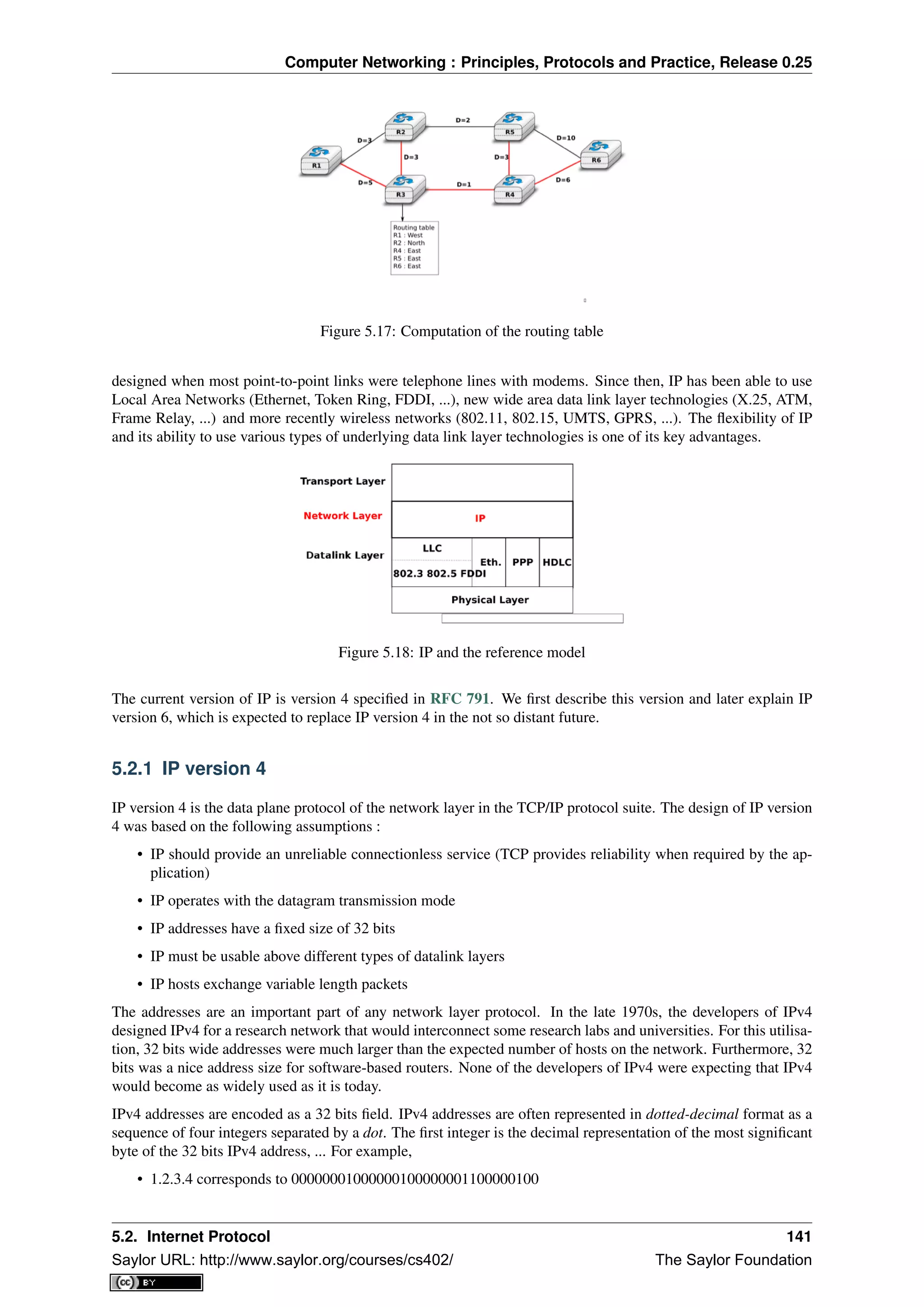
![Computer Networking : Principles, Protocols and Practice, Release 0.25
• 127.0.0.1 corresponds to 01111111000000000000000000000001
• 255.255.255.255 corresponds to 11111111111111111111111111111111
An IPv4 address is used to identify an interface on a router or a host. A router has thus as many IPv4 addresses as
the number of interfaces that it has in the datalink layer. Most hosts have a single datalink layer interface and thus
have a single IPv4 address. However, with the growth of wireless, more and more hosts have several datalink layer
interfaces (e.g. an Ethernet interface and a WiFi interface). These hosts are said to be multihomed. A multihomed
host with two interfaces has thus two IPv4 addresses.
An important point to be defined in a network layer protocol is the allocation of the network layer addresses. A
naive allocation scheme would be to provide an IPv4 address to each host when the host is attached to the Internet
on a first come first served basis. With this solution, a host in Belgium could have address 2.3.4.5 while another
host located in Africa would use address 2.3.4.6. Unfortunately, this would force all routers to maintain a specific
route towards each host. The figure below shows a simple enterprise network with two routers and three hosts and
the associated routing tables if such isolated addresses were used.
Figure 5.19: Scalability issues when using isolated IP addresses
To preserve the scalability of the routing system, it is important to minimize the number of routes that are stored on
each router. A router cannot store and maintain one route for each of the almost 1 billion hosts that are connected
to today’s Internet. Routers should only maintain routes towards blocks of addresses and not towards individual
hosts. For this, hosts are grouped in subnets based on their location in the network. A typical subnet groups
all the hosts that are part of the same enterprise. An enterprise network is usually composed of several LANs
interconnected by routers. A small block of addresses from the Enterprise’s block is usually assigned to each
LAN. An IPv4 address is composed of two parts : a subnetwork identifier and a host identifier. The subnetwork
identifier is composed of the high order bits of the address and the host identifier is encoded in the low order bits
of the address. This is illustrated in the figure below.
Figure 5.20: The subnetwork and host identifiers inside an IPv4 address
When a router needs to forward a packet, it must know the subnet of the destination address to be able to consult
its forwarding table to forward the packet. RFC 791 proposed to use the high-order bits of the address to encode
the length of the subnet identifier. This led to the definition of three classes of unicast addresses 2
2 In addition to the A, B and C classes, RFC 791 also defined the D and E classes of IPv4 addresses. Class D (resp. E) addresses are those
whose high order bits are set to 1110 (resp. 1111). Class D addresses are used by IP multicast and will be explained later. Class E addresses
are currently unused, but there are some discussions on possible future usages [WMH2008] [FLM2008]
142 Chapter 5. The network layer
Saylor URL: http://www.saylor.org/courses/cs402/ The Saylor Foundation](https://image.slidesharecdn.com/computer-networking-principles-bonaventure-1-30-31-otc1-150825141809-lva1-app6891/75/Computer-networking-principles-bonaventure-1-30-31-otc1-146-2048.jpg)
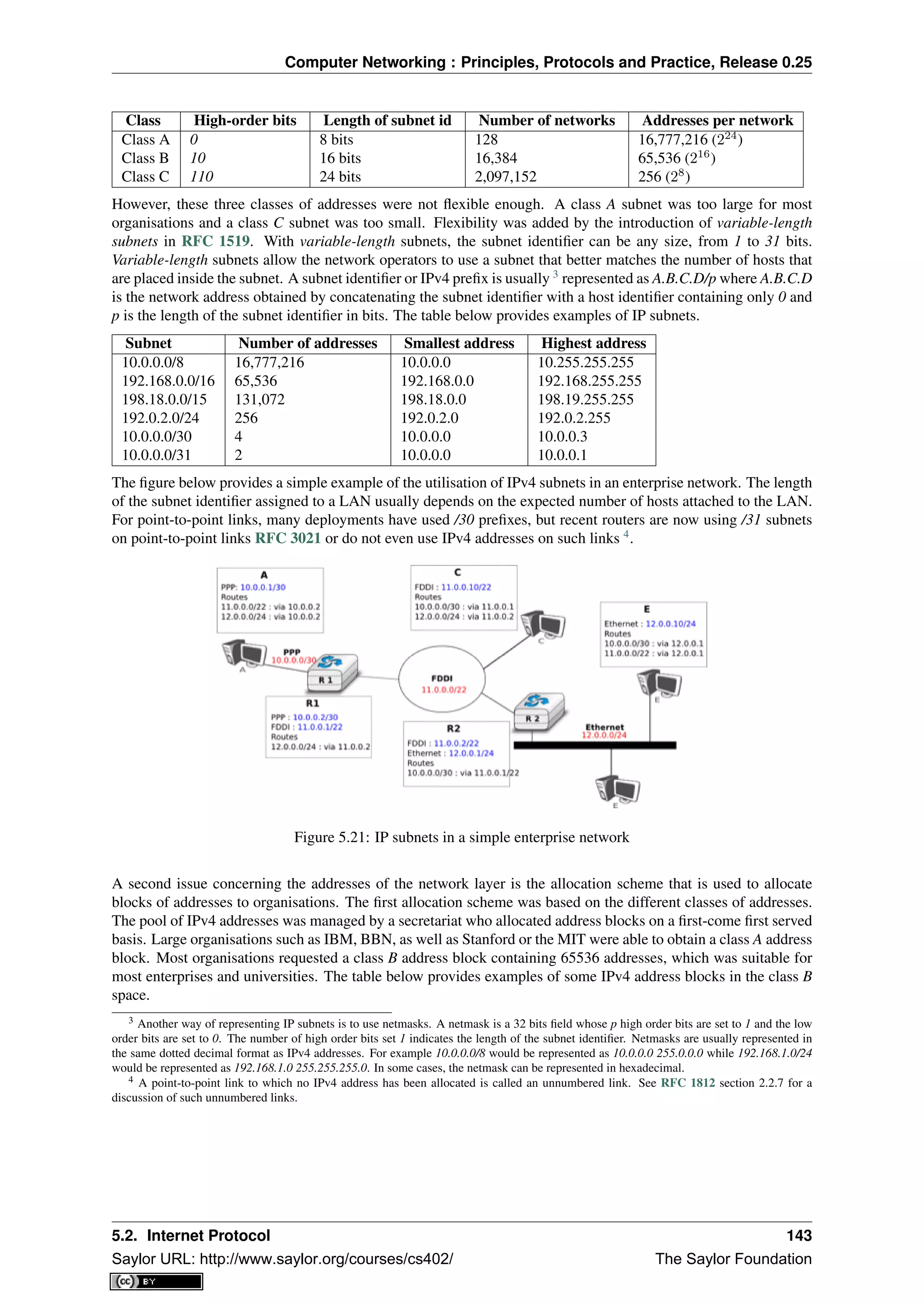
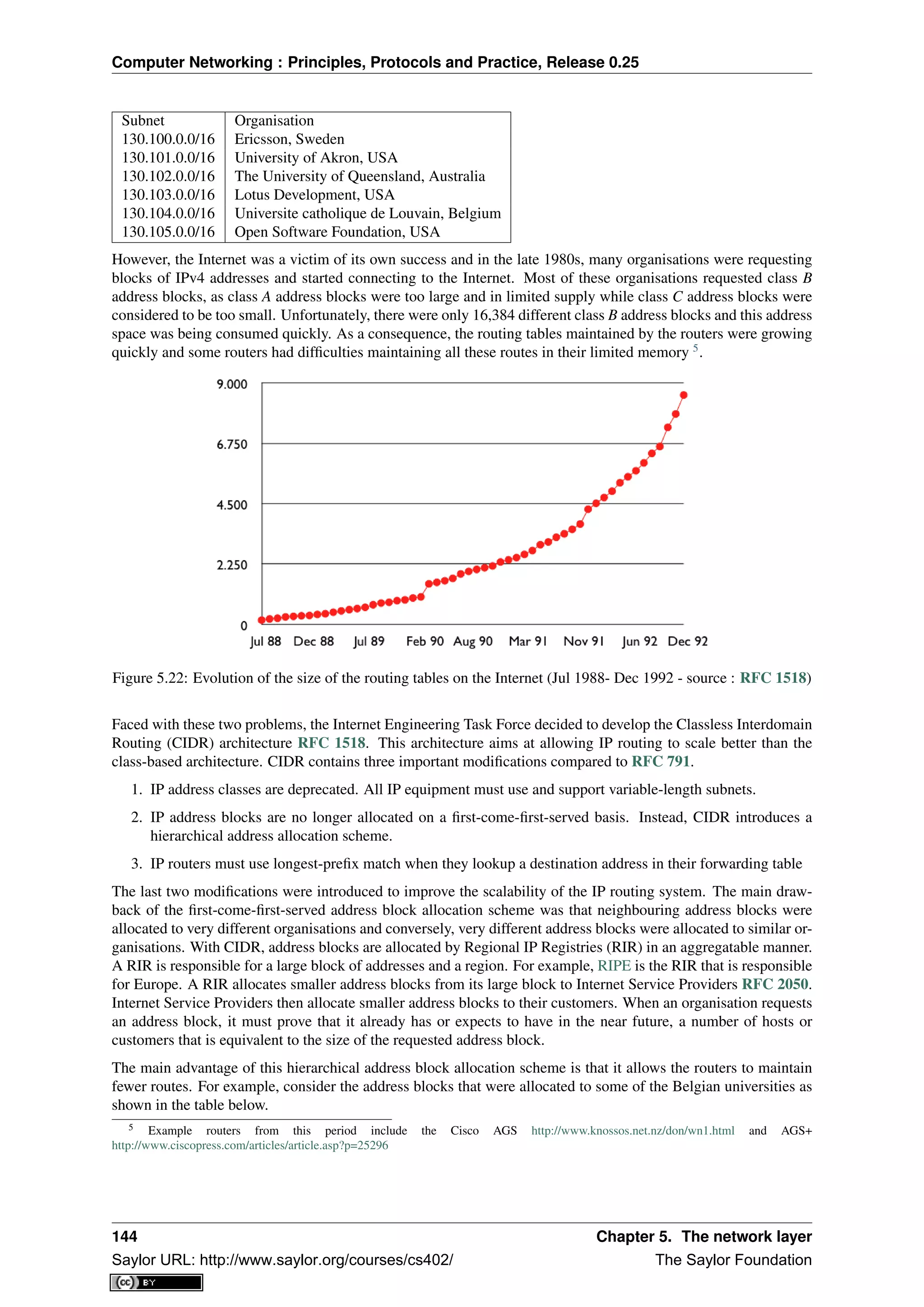
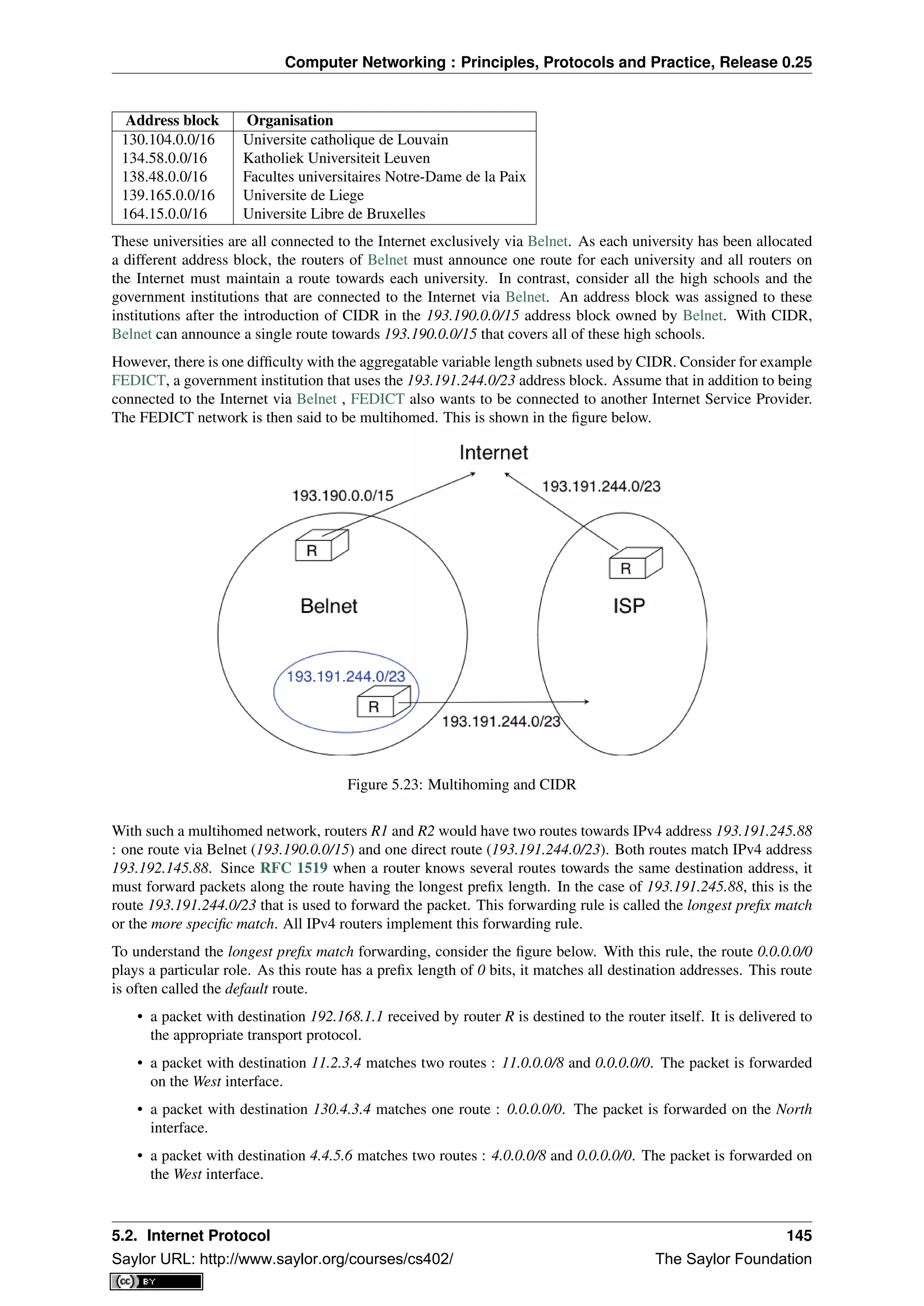
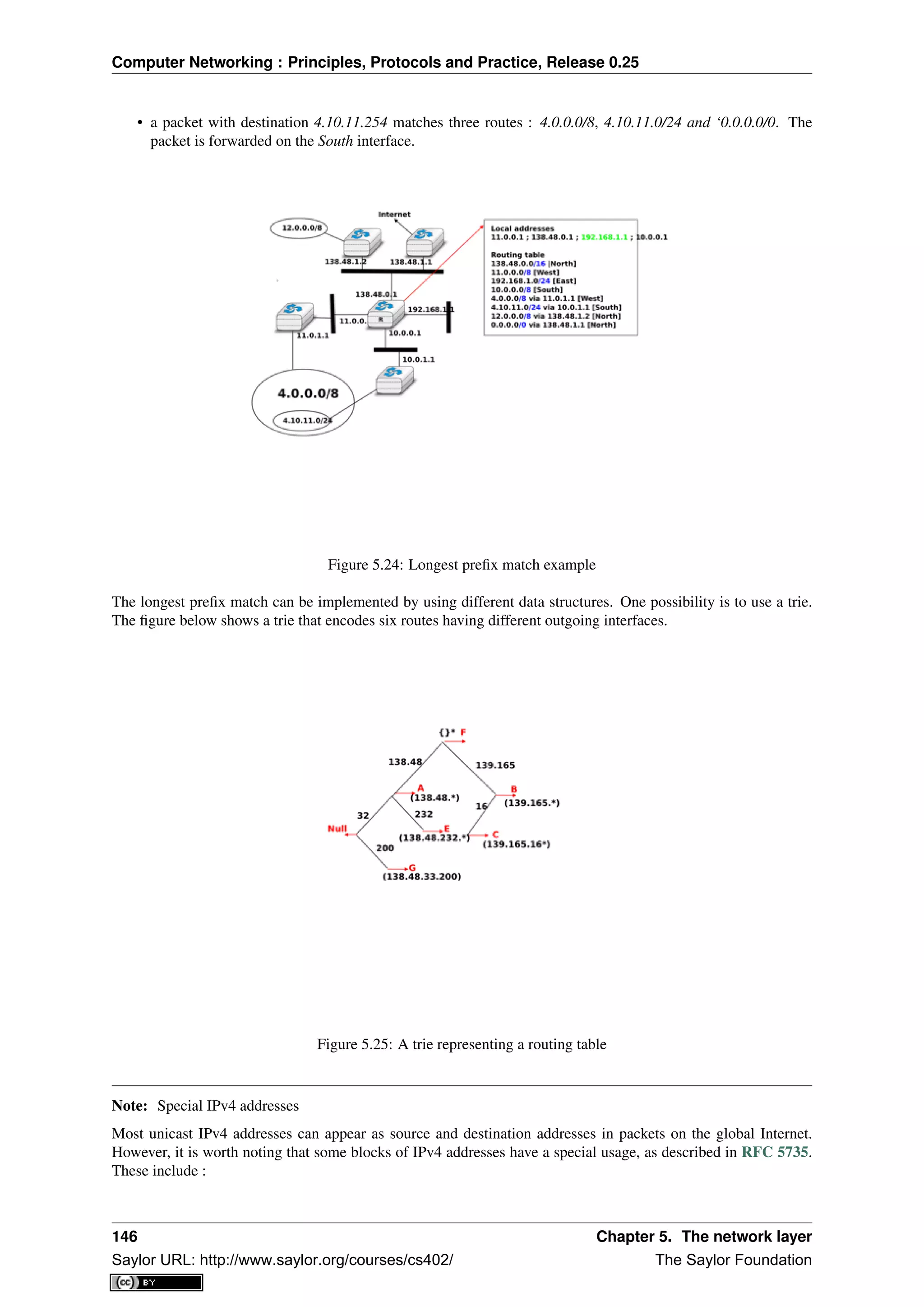
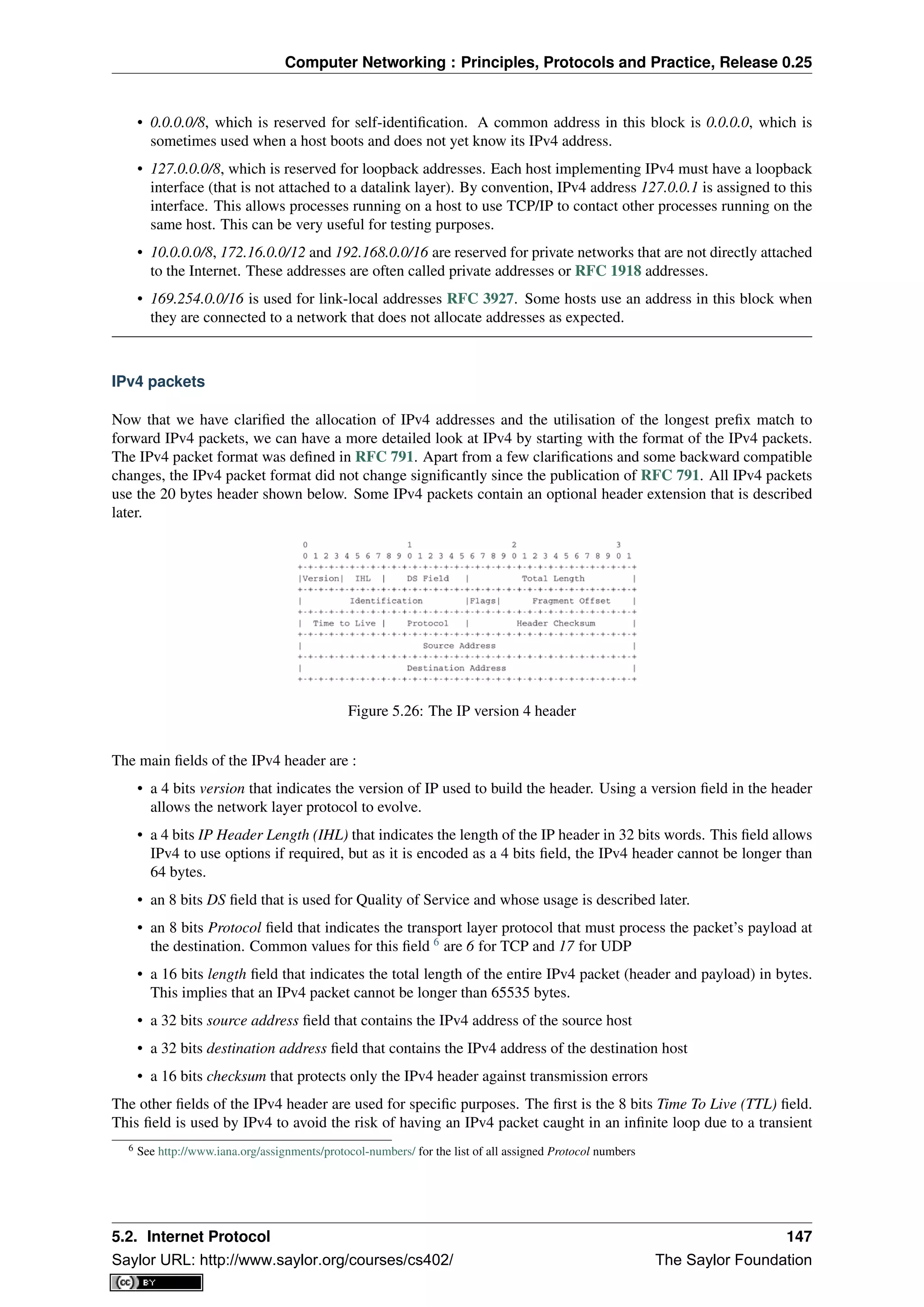
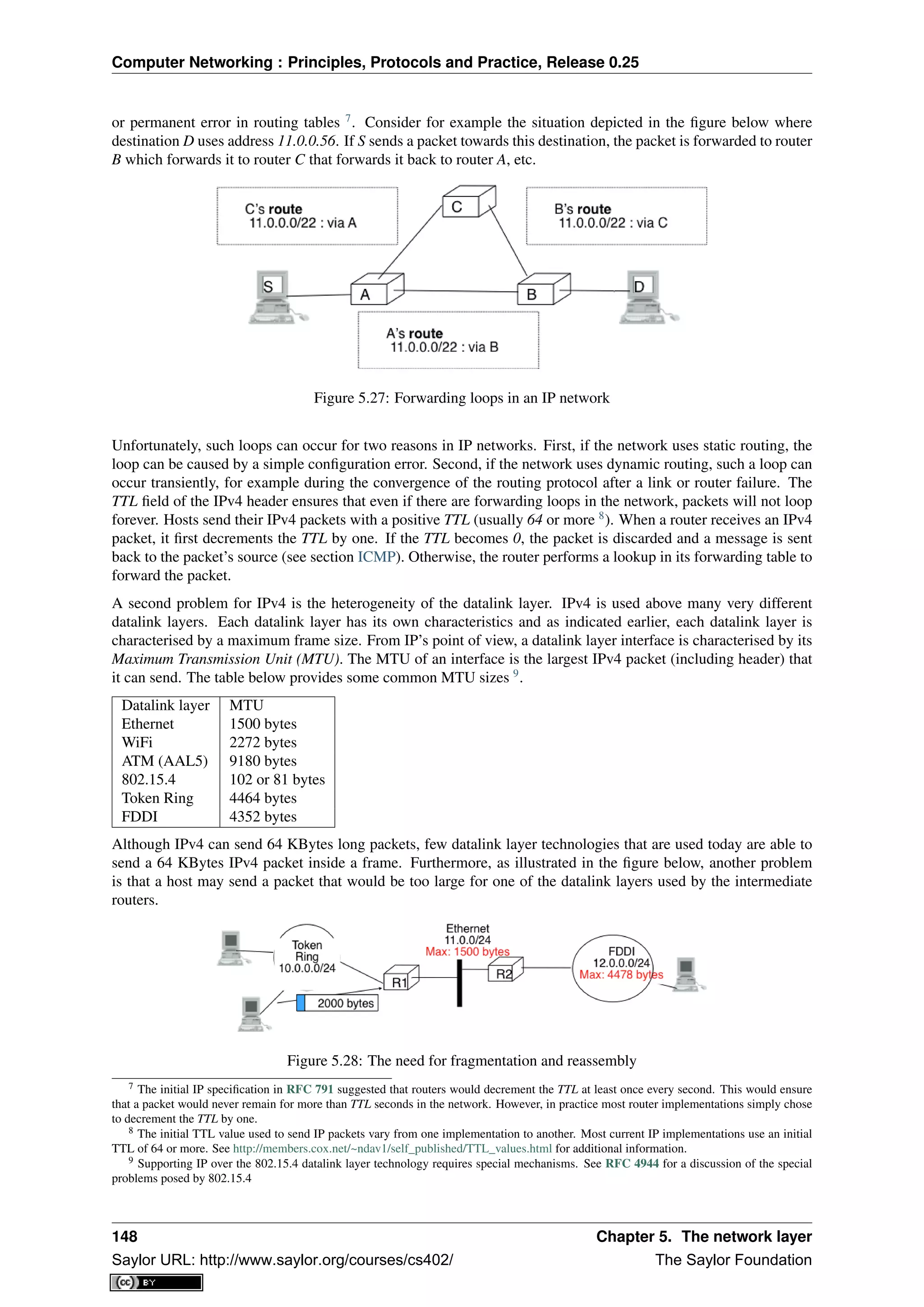
![Computer Networking : Principles, Protocols and Practice, Release 0.25
To solve these problems, IPv4 includes a packet fragmentation and reassembly mechanism. Both hosts and inter-
mediate routers may fragment an IPv4 packet if the packet is too long to be sent via the datalink layer. In IPv4,
fragmentation is completely performed in the IP layer and a large IPv4 is fragmented into two or more IPv4 pack-
ets (called fragments). The IPv4 fragments of a large packet are normal IPv4 packets that are forwarded towards
the destination of the large packet by intermediate routers.
The IPv4 fragmentation mechanism relies on four fields of the IPv4 header : Length, Identification, the flags and
the Fragment Offset. The IPv4 header contains two flags : More fragments and Don’t Fragment (DF). When the
DF flag is set, this indicates that the packet cannot be fragmented.
The basic operation of the IPv4 fragmentation is as follows. A large packet is fragmented into two or more
fragments. The size of all fragments, except the last one, is equal to the Maximum Transmission Unit of the link
used to forward the packet. Each IPv4 packet contains a 16 bits Identification field. When a packet is fragmented,
the Identification of the large packet is copied in all fragments to allow the destination to reassemble the received
fragments together. In each fragment, the Fragment Offset indicates, in units of 8 bytes, the position of the payload
of the fragment in the payload of the original packet. The Length field in each fragment indicates the length of
the payload of the fragment as in a normal IPv4 packet. Finally, the More fragments flag is set only in the last
fragment of a large packet.
The following pseudo-code details the IPv4 fragmentation, assuming that the packet does not contain options.
#mtu : maximum size of the packet (including header) of outgoing link
if p.len < mtu :
send(p)
# packet is too large
maxpayload=8*int((mtu-20)/8) # must be n times 8 bytes
if p.flags==’DF’ :
discard(p)
# packet must be fragmented
payload=p[IP].payload
pos=0
while len(payload) > 0 :
if len(payload) > maxpayload :
toSend=IP(dest=p.dest,src=p.src,
ttl=p.ttl, id=p.id,
frag=p.frag+(pos/8),
len=mtu, proto=p.proto)/payload[0:maxpayload]
pos=pos+maxpayload
payload=payload[maxpayload+1:]
else
toSend=IP(dest=p.dest,src=p.src,
ttl=p.ttl, id=p.id,
frag=p.frag+(pos/8),
flags=p.flags,
len=len(payload), proto=p.proto)/payload
forward(toSend)
The fragments of an IPv4 packet may arrive at the destination in any order, as each fragment is forwarded inde-
pendently in the network and may follow different paths. Furthermore, some fragments may be lost and never
reach the destination.
The reassembly algorithm used by the destination host is roughly as follows. First, the destination can verify
whether a received IPv4 packet is a fragment or not by checking the value of the More fragments flag and the
Fragment Offset. If the Fragment Offset is set to 0 and the More fragments flag is reset, the received packet has not
been fragmented. Otherwise, the packet has been fragmented and must be reassembled. The reassembly algorithm
relies on the Identification field of the received fragments to associate a fragment with the corresponding packet
being reassembled. Furthermore, the Fragment Offset field indicates the position of the fragment payload in the
original unfragmented packet. Finally, the packet with the More fragments flag reset allows the destination to
determine the total length of the original unfragmented packet.
Note that the reassembly algorithm must deal with the unreliability of the IP network. This implies that a fragment
may be duplicated or a fragment may never reach the destination. The destination can easily detect fragment
duplication thanks to the Fragment Offset. To deal with fragment losses, the reassembly algorithm must bound the
5.2. Internet Protocol 149
Saylor URL: http://www.saylor.org/courses/cs402/ The Saylor Foundation](https://image.slidesharecdn.com/computer-networking-principles-bonaventure-1-30-31-otc1-150825141809-lva1-app6891/75/Computer-networking-principles-bonaventure-1-30-31-otc1-153-2048.jpg)
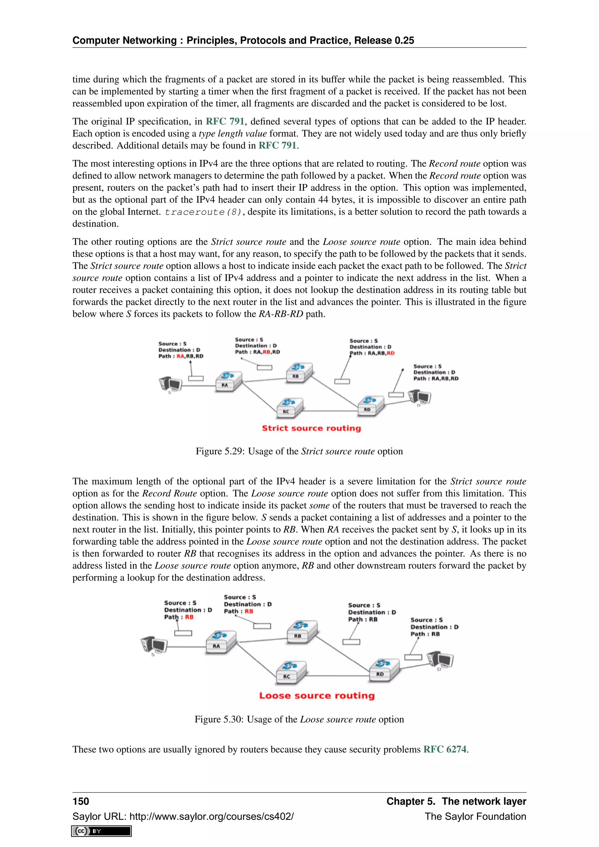
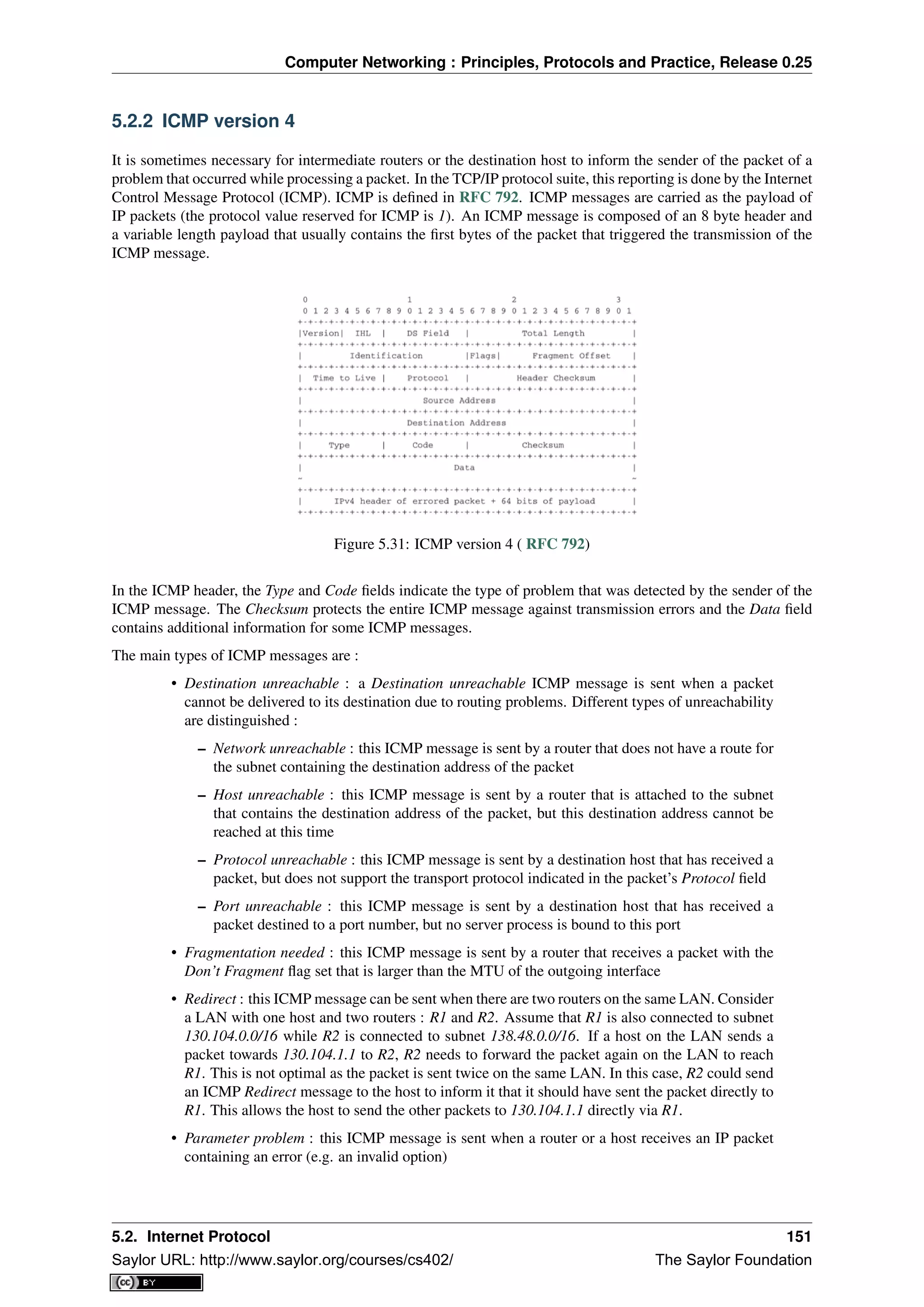
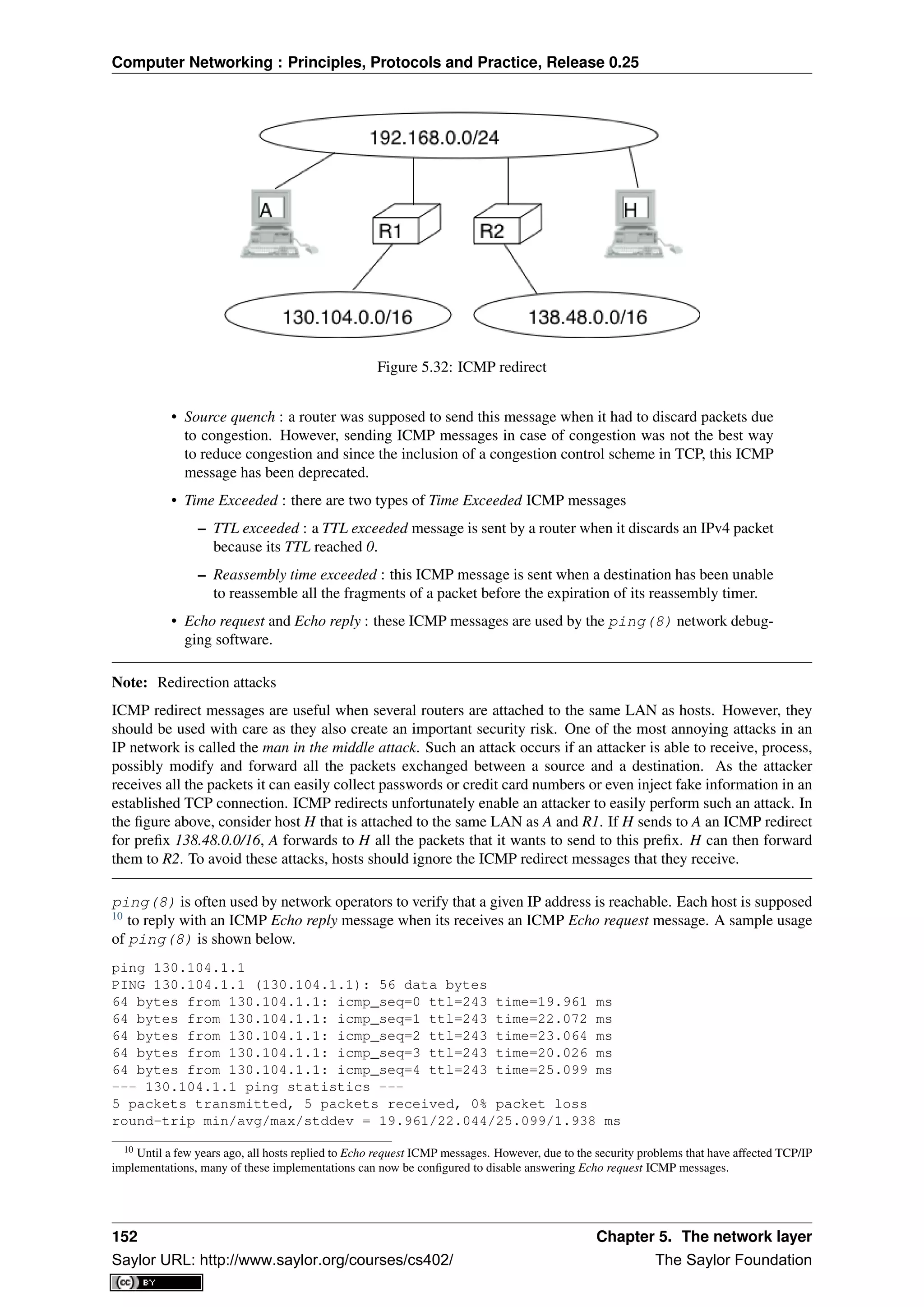
![Computer Networking : Principles, Protocols and Practice, Release 0.25
Another very useful debugging tool is traceroute(8). The traceroute man page describes this tool as “print
the route packets take to network host”. traceroute uses the TTL exceeded ICMP messages to discover the inter-
mediate routers on the path towards a destination. The principle behind traceroute is very simple. When a router
receives an IP packet whose TTL is set to 1 it decrements the TTL and is forced to return to the sending host a
TTL exceeded ICMP message containing the header and the first bytes of the discarded IP packet. To discover all
routers on a network path, a simple solution is to first send a packet whose TTL is set to 1, then a packet whose
TTL is set to 2, etc. A sample traceroute output is shown below.
traceroute www.ietf.org
traceroute to www.ietf.org (64.170.98.32), 64 hops max, 40 byte packets
1 CsHalles3.sri.ucl.ac.be (192.168.251.230) 5.376 ms 1.217 ms 1.137 ms
2 CtHalles.sri.ucl.ac.be (192.168.251.229) 1.444 ms 1.669 ms 1.301 ms
3 CtPythagore.sri.ucl.ac.be (130.104.254.230) 1.950 ms 4.688 ms 1.319 ms
4 fe.m20.access.lln.belnet.net (193.191.11.9) 1.578 ms 1.272 ms 1.259 ms
5 10ge.cr2.brueve.belnet.net (193.191.16.22) 5.461 ms 4.241 ms 4.162 ms
6 212.3.237.13 (212.3.237.13) 5.347 ms 4.544 ms 4.285 ms
7 ae-11-11.car1.Brussels1.Level3.net (4.69.136.249) 5.195 ms 4.304 ms 4.329 ms
8 ae-6-6.ebr1.London1.Level3.net (4.69.136.246) 8.892 ms 8.980 ms 8.830 ms
9 ae-100-100.ebr2.London1.Level3.net (4.69.141.166) 8.925 ms 8.950 ms 9.006 ms
10 ae-41-41.ebr1.NewYork1.Level3.net (4.69.137.66) 79.590 ms
ae-43-43.ebr1.NewYork1.Level3.net (4.69.137.74) 78.140 ms
ae-42-42.ebr1.NewYork1.Level3.net (4.69.137.70) 77.663 ms
11 ae-2-2.ebr1.Newark1.Level3.net (4.69.132.98) 78.290 ms 83.765 ms 90.006 ms
12 ae-14-51.car4.Newark1.Level3.net (4.68.99.8) 78.309 ms 78.257 ms 79.709 ms
13 ex1-tg2-0.eqnwnj.sbcglobal.net (151.164.89.249) 78.460 ms 78.452 ms 78.292 ms
14 151.164.95.190 (151.164.95.190) 157.198 ms 160.767 ms 159.898 ms
15 ded-p10-0.pltn13.sbcglobal.net (151.164.191.243) 161.872 ms 156.996 ms 159.425 ms
16 AMS-1152322.cust-rtr.swbell.net (75.61.192.10) 158.735 ms 158.485 ms 158.588 ms
17 mail.ietf.org (64.170.98.32) 158.427 ms 158.502 ms 158.567 ms
The above traceroute(8) output shows a 17 hops path between a host at UCLouvain and one of the main
IETF servers. For each hop, traceroute provides the IPv4 address of the router that sent the ICMP message and the
measured round-trip-time between the source and this router. traceroute sends three probes with each TTL value.
In some cases, such as at the 10th hop above, the ICMP messages may be received from different addresses. This
is usually because different packets from the same source have followed different paths 11
in the network.
Another important utilisation of ICMP messages is to discover the maximum MTU that can be used to reach a
destination without fragmentation. As explained earlier, when an IPv4 router receives a packet that is larger than
the MTU of the outgoing link, it must fragment the packet. Unfortunately, fragmentation is a complex operation
and routers cannot perform it at line rate [KM1995]. Furthermore, when a TCP segment is transported in an IP
packet that is fragmented in the network, the loss of a single fragment forces TCP to retransmit the entire segment
(and thus all the fragments). If TCP was able to send only packets that do not require fragmentation in the
network, it could retransmit only the information that was lost in the network. In addition, IP reassembly causes
several challenges at high speed as discussed in RFC 4963. Using IP fragmentation to allow UDP applications to
exchange large messages raises several security issues [KPS2003].
ICMP, combined with the Don’t fragment (DF) IPv4 flag, is used by TCP implementations to discover the largest
MTU size that is allowed to reach a destination host without causing network fragmentation. This is the Path MTU
discovery mechanism defined in RFC 1191. A TCP implementation that includes Path MTU discovery (most do)
requests the IPv4 layer to send all segments inside IPv4 packets having the DF flag set. This prohibits intermediate
routers from fragmenting these packets. If a router needs to forward an unfragmentable packet over a link with a
smaller MTU, it returns a Fragmentation needed ICMP message to the source, indicating the MTU of its outgoing
link. This ICMP message contains in the MTU of the router’s outgoing link in its Data field. Upon reception of
this ICMP message, the source TCP implementation adjusts its Maximum Segment Size (MSS) so that the packets
containing the segments that it sends can be forwarded by this router without requiring fragmentation.
11 A detailed analysis of traceroute output is outside the scope of this document. Additional information may be found in [ACO+2006] and
[DT2007]
5.2. Internet Protocol 153
Saylor URL: http://www.saylor.org/courses/cs402/ The Saylor Foundation](https://image.slidesharecdn.com/computer-networking-principles-bonaventure-1-30-31-otc1-150825141809-lva1-app6891/75/Computer-networking-principles-bonaventure-1-30-31-otc1-157-2048.jpg)
![Computer Networking : Principles, Protocols and Practice, Release 0.25
Interactions between IPv4 and the datalink layer
As mentioned in the first section of this chapter, there are three main types of datalink layers : point-to-point links,
LANs supporting broadcast and multicast and NBMA networks. There are two important issues to be addressed
when using IPv4 in these types of networks. The first issue is how an IPv4 device obtains its IPv4 address. The
second issue is how IPv4 packets are exchanged over the datalink layer service.
On a point-to-point link, the IPv4 addresses of the communicating devices can be configured manually or by
using a simple protocol. IPv4 addresses are often configured manually on point-to-point links between routers.
When point-to-point links are used to attach hosts to the network, automatic configuration is often preferred in
order to avoid problems with incorrect IPv4 addresses. For example, the PPP, specified in RFC 1661, includes
an IP network control protocol that can be used by the router in the figure below to send the IPv4 address that the
attached host must configure for its interface. The transmission of IPv4 packets on a point-to-point link will be
discussed in chapter chap:lan.
Figure 5.33: IPv4 on point-to-point links
Using IPv4 in a LAN introduces an additional problem. On a LAN, each device is identified by its unique datalink
layer address. The datalink layer service can be used by any host attached to the LAN to send a frame to any other
host attached to the same LAN. For this, the sending host must know the datalink layer address of the destination
host. For example, the figure below shows four hosts attached to the same LAN configured with IPv4 addresses
in the 10.0.1.0/24 subnet and datalink layer addresses represented as a single character 12
. In this network, if host
10.0.1.22/24 wants to send an IPv4 packet to the host having address 10.0.1.8, it must know that the datalink layer
address of this host is C.
Figure 5.34: A simple LAN
In a simple network such as the one shown above, it could be possible to manually configure the mapping between
the IPv4 addresses of the hosts and the corresponding datalink layer addresses. However, in a larger LAN this is
impossible. To ease the utilisation of LANs, IPv4 hosts must be able to automatically obtain the datalink layer
address corresponding to any IPv4 address on the same LAN. This is the objective of the Address Resolution
Protocol (ARP) defined in RFC 826. ARP is a datalink layer protocol that is used by IPv4. It relies on the ability
of the datalink layer service to easily deliver a broadcast frame to all devices attached to the same LAN.
12 In practice, most local area networks use addresses encoded as a 48 bits field [802]_ . Some recent local area network technologies use
64 bits addresses.
154 Chapter 5. The network layer
Saylor URL: http://www.saylor.org/courses/cs402/ The Saylor Foundation](https://image.slidesharecdn.com/computer-networking-principles-bonaventure-1-30-31-otc1-150825141809-lva1-app6891/75/Computer-networking-principles-bonaventure-1-30-31-otc1-158-2048.jpg)
![Computer Networking : Principles, Protocols and Practice, Release 0.25
The easiest way to understand the operation of ARP is to consider the simple network shown above and assume
that host 10.0.1.22/24 needs to send an IPv4 packet to host 10.0.1.8. As this IP address belongs to the same
subnet, the packet must be sent directly to its destination via the datalink layer service. To use this service, the
sending host must find the datalink layer address that is attached to host 10.0.1.8. Each IPv4 host maintains an
ARP cache containing the list of all mappings between IPv4 addresses and datalink layer addresses that it knows.
When an IPv4 hosts boots, its ARP cache is empty. 10.0.1.22 thus first consults its ARP cache. As the cache
does not contain the requested mapping, host 10.0.1.22 sends a broadcast ARP query frame on the LAN. The
frame contains the datalink layer address of the sending host (A) and the requested IPv4 address (10.0.1.8). This
broadcast frame is received by all devices on the LAN and only the host that owns the requested IPv4 address
replies by returning a unicast ARP reply frame with the requested mapping. Upon reception of this reply, the
sending host updates its ARP cache and sends the IPv4 packet by using the datalink layer service. To deal with
devices that move or whose addresses are reconfigured, most ARP implementations remove the cache entries that
have not been used for a few minutes. Some implementations re-validate ARP cache entries from time to time by
sending ARP queries 13
.
Note: Security issues with the Address Resolution Protocol
ARP is an old and widely used protocol that was unfortunately designed when security issues were not a concern.
ARP is almost insecure by design. Hosts using ARP can be subject to several types of attack. First, a malicious
host could create a denial of service attack on a LAN by sending random replies to the received ARP queries.
This would pollute the ARP cache of the other hosts on the same LAN. On a fixed network, such attacks can be
detected by the system administrator who can physically remove the malicious hosts from the LAN. On a wireless
network, removing a malicious host is much more difficult.
A second type of attack are the man-in-the-middle attacks. This name is used for network attacks where the
attacker is able to read and possibly modify all the messages sent by the attacked devices. Such an attack is
possible in a LAN. Assume, in the figure above, that host 10.0.1.9 is malicious and would like to receive and
modify all the packets sent by host 10.0.1.22 to host 10.0.1.8. This can be achieved easily if host 10.0.1.9 manages,
by sending fake ARP replies, to convince host 10.0.1.22 (resp. 10.0.1.8) that its own datalink layer address must
be used to reach 10.0.1.8 (resp. 10.0.1.22).
ARP is used by all devices that are connected to a LAN and implement IPv4. Both routers and endhosts implement
ARP. When a host needs to send an IPv4 packet to a destination outside of its local subnet, it must first send the
packet to one of the routers that reside on this subnet. Consider for example the network shown in the figure
below. Each host is configured with an IPv4 address in the 10.0.1.0/24 subnet and uses 10.0.1.1 as its default
router. To send a packet to address 1.2.3.4, host 10.0.1.8 will first need to know the datalink layer of the default
router. It will thus send an ARP request for 10.0.1.1. Upon reception of the ARP reply, host 10.0.1.8 updates its
ARP table and sends its packet in a frame to its default router. The router will then forward the packet towards its
final destination.
Figure 5.35: A simple LAN with a router
In the early days of the Internet, IP addresses were manually configured on both hosts and routers and almost never
changed. However, this manual configuration can be complex 14
and often causes errors that are sometimes diffi-
cult to debug. Recent TCP/IP implementations are able to detect some of these misconfigurations. For example,
if two hosts are attached to the same subnet with the same IPv4 address they will be unable to communicate. To
detect this problem hosts send an ARP request for their configured address each time their addressed is changed
RFC 5227. If they receive an answer to this ARP request, they trigger an alarm or inform the system administrator.
13 See chapter 28 of [Benvenuti2005] for a description of the implementation of ARP in the Linux kernel.
14 For example, consider all the options that can be specified for the ifconfig utility<http://en.wikipedia.org/wiki/Ifconfig> on Unix hosts.
5.2. Internet Protocol 155
Saylor URL: http://www.saylor.org/courses/cs402/ The Saylor Foundation](https://image.slidesharecdn.com/computer-networking-principles-bonaventure-1-30-31-otc1-150825141809-lva1-app6891/75/Computer-networking-principles-bonaventure-1-30-31-otc1-159-2048.jpg)
![Computer Networking : Principles, Protocols and Practice, Release 0.25
2 minutes, this implies that the maximum bandwidth to a given destination is limited to roughly 286 Mbps. With
a more realistic 1500 bytes MTU, that bandwidth drops to 6.4 Mbps RFC 4963 if fragmentation must be possible
17
. This is very low and is another reason why hosts are highly encouraged to avoid fragmentation. If; despite all
of this, the MTU of the outgoing interface is smaller than the packet’s length, the packet is fragmented. Finally,
the packet’s checksum is computed before transmission.
When a host receives an IPv4 packet destined to itself, there are several operations that it must perform. First,
it must check the packet’s checksum. If the checksum is incorrect, the packet is discarded. Then, it must check
whether the packet has been fragmented. If yes, the packet is passed to the reassembly algorithm described earlier.
Otherwise, the packet must be passed to the upper layer. This is done by looking at the Protocol field (6 for TCP,
17 for UDP). If the host does not implement the transport layer protocol corresponding to the received Protocol
field, it sends a Protocol unreachable ICMP message to the sending host. If the received packet contains an ICMP
message (Protocol field set to 1), the processing is more complex. An Echo-request ICMP message triggers the
transmission of an ICMP Echo-reply message. The other types of ICMP messages indicate an error that was
caused by a previously transmitted packet. These ICMP messages are usually forwarded to the transport protocol
that sent the erroneous packet. This can be done by inspecting the contents of the ICMP message that includes
the header and the first 64 bits of the erroneous packet. If the IP packet did not contain options, which is the case
for most IPv4 packets, the transport protocol can find in the first 32 bits of the transport header the source and
destination ports to determine the affected transport flow. This is important for Path MTU discovery for example.
When a router receives an IPv4 packet, it must first check the packet’s checksum. If the checksum is invalid, it is
discarded. Otherwise, the router must check whether the destination address is one of the IPv4 addresses assigned
to the router. If so, the router must behave as a host and process the packet as described above. Although routers
mainly forward IPv4 packets, they sometimes need to be accessed as hosts by network operators or network
management software.
If the packet is not addressed to the router, it must be forwarded on an outgoing interface according to the router’s
routing table. The router first decrements the packet’s TTL. If the TTL reaches 0, a TTL Exceeded ICMP message is
sent back to the source. As the packet header has been modified, the checksum must be recomputed. Fortunately,
as IPv4 uses an arithmetic checksum, a router can incrementally update the packet’s checksum as described in
RFC 1624. Then, the router performs a longest prefix match for the packet’s destination address in its forwarding
table. If no match is found, the router must return a Destination unreachable ICMP message to the source.
Otherwise, the lookup returns the interface over which the packet must be forwarded. Before forwarding the
packet over this interface, the router must first compare the length of the packet with the MTU of the outgoing
interface. If the packet is smaller than the MTU, it is forwarded. Otherwise, a Fragmentation needed ICMP
message is sent if the DF flag was sent or the packet is fragmented if the DF was not set.
Note: Longest prefix match in IP routers
Performing the longest prefix match at line rate on routers requires highly tuned data structures and algorithms.
Consider for example an implementation of the longest match based on a Radix tree on a router with a 10 Gbps
link. On such a link, a router can receive 31,250,000 40 bytes IPv4 packets every second. To forward the packets
at line rate, the router must process one IPv4 packet every 32 nanoseconds. This cannot be achieved by a software
implementation. For a hardware implementation, the main difficulty lies in the number of memory accesses that
are necessary to perform the longest prefix match. 32 nanoseconds is very small compared to the memory accesses
that are required by a naive longest prefix match implement. Additional information about faster longest prefix
match algorithms may be found in [Varghese2005].
5.2.3 IP version 6
In the late 1980s and early 1990s the growth of the Internet was causing several operational problems on routers.
Many of these routers had a single CPU and up to 1 MByte of RAM to store their operating system, packet buffers
and routing tables. Given the rate of allocation of IPv4 prefixes to companies and universities willing to join the
Internet, the routing tables where growing very quickly and some feared that all IPv4 prefixes would quickly be
allocated. In 1987, a study cited in RFC 1752, estimated that there would be 100,000 networks in the near future.
In August 1990, estimates indicated that the class B space would be exhausted by March 1994. Two types of
17 It should be noted that only the packets that can be fragmented (i.e. whose DF flag is reset) must have different Identification fields. The
Identification field is not used in the packets having the DF flag set.
5.2. Internet Protocol 157
Saylor URL: http://www.saylor.org/courses/cs402/ The Saylor Foundation](https://image.slidesharecdn.com/computer-networking-principles-bonaventure-1-30-31-otc1-150825141809-lva1-app6891/75/Computer-networking-principles-bonaventure-1-30-31-otc1-161-2048.jpg)
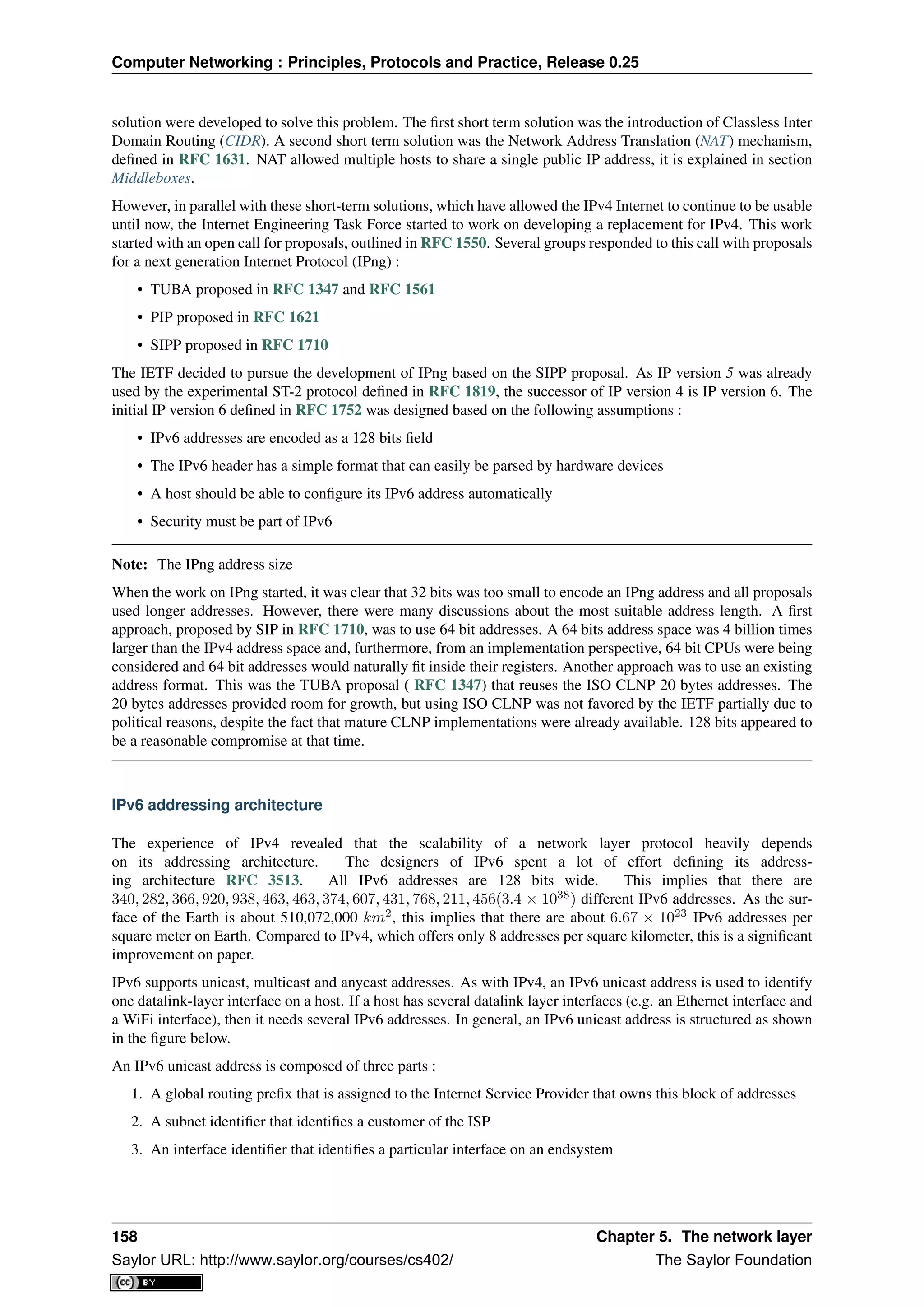
![Computer Networking : Principles, Protocols and Practice, Release 0.25
Figure 5.36: Structure of IPv6 unicast addresses
In today’s deployments, interface identifiers are always 64 bits wide. This implies that while there are 2128
different IPv6 addresses, they must be grouped in 264
subnets. This could appear as a waste of resources, however
using 64 bits for the host identifier allows IPv6 addresses to be auto-configured and also provides some benefits
from a security point of view, as explained in section ICMPv6
Note: Textual representation of IPv6 addresses
It is sometimes necessary to write IPv6 addresses in text format, e.g. when manually configuring addresses or for
documentation purposes. The preferred format for writing IPv6 addresses is x:x:x:x:x:x:x:x, where the x ‘s are
hexadecimal digits representing the eight 16-bit parts of the address. Here are a few examples of IPv6 addresses :
• ABCD:EF01:2345:6789:ABCD:EF01:2345:6789
• 2001:DB8:0:0:8:800:200C:417A
• FE80:0:0:0:219:E3FF:FED7:1204
IPv6 addresses often contain a long sequence of bits set to 0. In this case, a compact notation has been defined.
With this notation, :: is used to indicate one or more groups of 16 bits blocks containing only bits set to 0. For
example,
• 2001:DB8:0:0:8:800:200C:417A is represented as 2001:DB8::8:800:200C:417A
• FF01:0:0:0:0:0:0:101 is represented as FF01::101
• 0:0:0:0:0:0:0:1 is represented as ::1
• 0:0:0:0:0:0:0:0 is represented as ::
An IPv6 prefix can be represented as address/length, where length is the length of the prefix in bits. For example,
the three notations below correspond to the same IPv6 prefix :
• 2001:0DB8:0000:CD30:0000:0000:0000:0000/60
• 2001:0DB8::CD30:0:0:0:0/60
• 2001:0DB8:0:CD30::/60
In practice, there are several types of IPv6 unicast address. Most of the IPv6 unicast addresses are allocated in
blocks under the responsibility of IANA. The current IPv6 allocations are part of the 2000::/3 address block.
Regional Internet Registries (RIR) such as RIPE in Europe, ARIN in North-America or AfriNIC in Africa have
each received a block of IPv6 addresses that they sub-allocate to Internet Service Providers in their region. The
ISPs then sub-allocate addresses to their customers.
When considering the allocation of IPv6 addresses, two types of address allocations are often distinguished. The
RIRs allocate provider-independent (PI) addresses. PI addresses are usually allocated to Internet Service Providers
and large companies that are connected to at least two different ISPs [CSP2009]. Once a PI address block has
been allocated to a company, this company can use its address block with the provider of its choice and change
its provider at will. Internet Service Providers allocate provider-aggregatable (PA) address blocks from their own
PI address block to their customers. A company that is connected to only one ISP should only use PA addresses.
5.2. Internet Protocol 159
Saylor URL: http://www.saylor.org/courses/cs402/ The Saylor Foundation](https://image.slidesharecdn.com/computer-networking-principles-bonaventure-1-30-31-otc1-150825141809-lva1-app6891/75/Computer-networking-principles-bonaventure-1-30-31-otc1-163-2048.jpg)
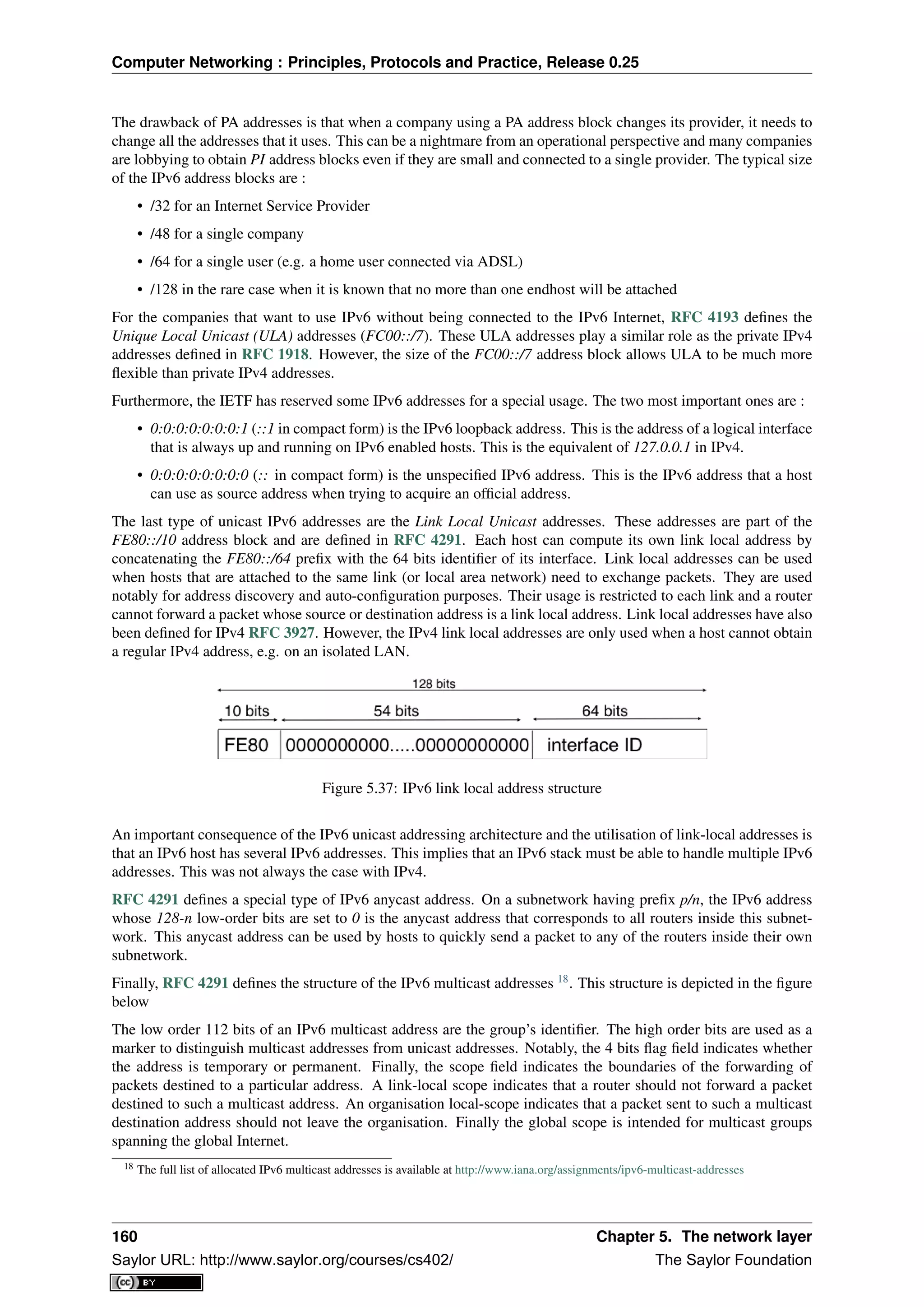
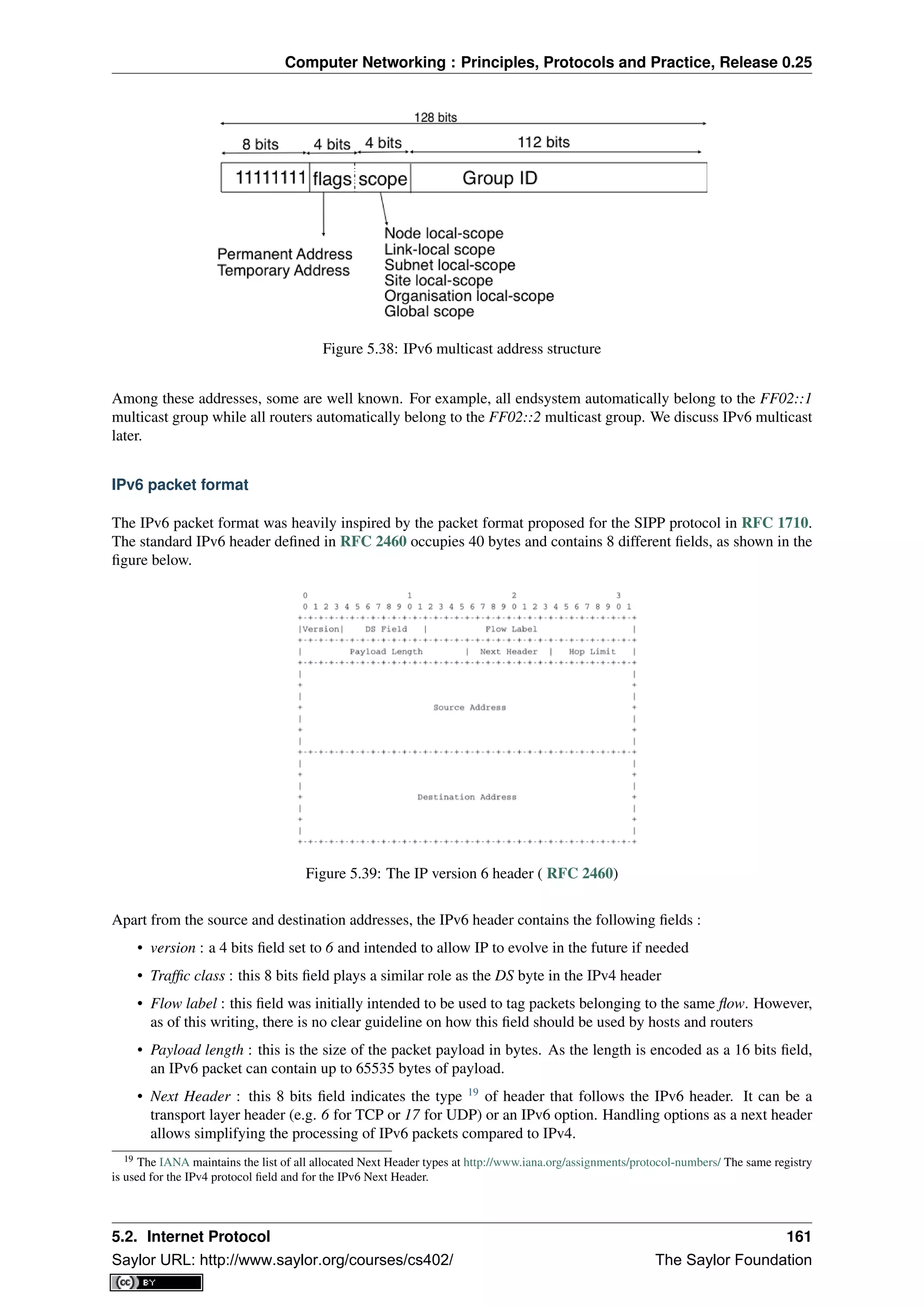
![Computer Networking : Principles, Protocols and Practice, Release 0.25
• Hop Limit : this 8 bits field indicates the number of routers that can forward the packet. It is decremented
by one by each router and has the same purpose as the TTL field of the IPv4 header.
In comparison with IPv4, the IPv6 packets are much simpler and easier to process by routers. A first important
difference is that there is no checksum inside the IPv6 header. This is mainly because all datalink layers and
transport protocols include a checksum or a CRC to protect their frames/segments against transmission errors.
Adding a checksum in the IPv6 header would have forced each router to recompute the checksum of all packets,
with limited benefit in detecting errors. In practice, an IP checksum allows for catching errors that occur inside
routers (e.g. due to memory corruption) before the packet reaches its destination. However, this benefit was found
to be too small given the reliability of current memories and the cost of computing the checksum on each router.
A second difference with IPv4 is that the IPv6 header does not support fragmentation and reassembly. Experience
with IPv4 has shown that fragmenting packets in routers was costly [KM1995] and the developers of IPv6 have
decided that routers would not fragment packets anymore. If a router receives a packet that is too long to be
forwarded, the packet is dropped and the router returns an ICMPv6 messages to inform the sender of the problem.
The sender can then either fragment the packet or perform Path MTU discovery. In IPv6, packet fragmentation is
performed only by the source by using IPv6 options.
The third difference are the IPv6 options, which are simpler and easier to process than the IPv4 options.
Note: Header compression on low bandwidth links
Given the size of the IPv6 header, it can cause huge overhead on low bandwidth links, especially when small
packets are exchanged such as for Voice over IP applications. In such environments, several techniques can be
used to reduce the overhead. A first solution is to use data compression in the datalink layer to compress all the
information exchanged [Thomborson1992]. These techniques are similar to the data compression algorithms used
in tools such as compress(1) or gzip(1) RFC 1951. They compress streams of bits without taking advantage
of the fact that these streams contain IP packets with a known structure. A second solution is to compress the IP
and TCP header. These header compression techniques, such as the one defined in RFC 2507 take advantage of
the redundancy found in successive packets from the same flow to significantly reduce the size of the protocol
headers. Another solution is to define a compressed encoding of the IPv6 header that matches the capabilities of
the underlying datalink layer RFC 4944.
IPv6 options
In IPv6, each option is considered as one header containing a multiple of 8 bytes to ensure that IPv6 options in a
packet are aligned on 64 bit boundaries. IPv6 defines several type of options :
• the hop-by-hop options are options that must be processed by the routers on the packet’s path
• the type 0 routing header, which is similar to the IPv4 loose source routing option
• the fragmentation option, which is used when fragmenting an IPv6 packet
• the destination options
• the security options that allow IPv6 hosts to exchange packets with cryptographic authentication (AH
header) or encryption and authentication (ESP header)
RFC 2460 provides lots of detail on the encodings of the different types of options. In this section, we only discus
some of them. The reader may consult RFC 2460 for more information about the other options. The first point to
note is that each option contains a Next Header field, which indicates the type of header that follows the option.
A second point to note is that in order to allow routers to efficiently parse IPv6 packets, the options that must be
processed by routers (hop-by-hop options and type 0 routing header) must appear first in the packet. This allows
the router to process a packet without being forced to analyse all the packet’s options. A third point to note is
that hop-by-hop and destination options are encoded using a type length value format. Furthermore, the type field
contains bits that indicate whether a router that does not understand this option should ignore the option or discard
the packet. This allows the introduction of new options into the network without forcing all devices to be upgraded
to support them at the same time.
Two hop-by-hop options have been defined. RFC 2675 specifies the jumbogram that enables IPv6 to support
packets containing a payload larger than 65535 bytes. These jumbo packets have their payload length set to 0 and
162 Chapter 5. The network layer
Saylor URL: http://www.saylor.org/courses/cs402/ The Saylor Foundation](https://image.slidesharecdn.com/computer-networking-principles-bonaventure-1-30-31-otc1-150825141809-lva1-app6891/75/Computer-networking-principles-bonaventure-1-30-31-otc1-166-2048.jpg)
![Computer Networking : Principles, Protocols and Practice, Release 0.25
the jumbogram option contains the packet length as a 32 bits field. Such packets can only be sent from a source
to a destination if all the routers on the path support this option. However, as of this writing it does not seem that
the jumbogram option has been implemented. The router alert option defined in RFC 2711 is the second example
of a hop-by-hop option. The packets that contain this option should be processed in a special way by intermediate
routers. This option is used for IP packets that carry Resource Reservation Protocol (RSVP) messages. Its usage
is explained later.
The type 0 routing header defined in RFC 2460 is an example of an IPv6 option that must be processed by some
routers. This option is encoded as shown below.
Figure 5.40: The Type 0 routing header ( RFC 2460)
The type 0 routing option was intended to allow a host to indicate a loose source route that should be followed by
a packet by specifying the addresses of some of the routers that must forward this packet. Unfortunately, further
work with this routing header, including an entertaining demonstration with scapy [BE2007] , revealed some
severe security problems with this routing header. For this reason, loose source routing with the type 0 routing
header has been removed from the IPv6 specification RFC 5095.
In IPv6, fragmentation is performed exclusively by the source host and relies on the fragmentation header. This
64 bits header is composed of six fields :
• a Next Header field that indicates the type of the header that follows the fragmentation header
• a reserved field set to 0.
• the Fragment Offset is a 13-bit unsigned integer that contains the offset, in 8 bytes units, of the data following
this header, relative to the start of the original packet.
• the More flag, which is set to 0 in the last fragment of a packet and to 1 in all other fragments.
• the 32 bits Identification field indicates to which original packet a fragment belongs. When a host sends
fragmented packets, it should ensure that it does not reuse the same identification field for packets sent to
the same destination during a period of MSL seconds. This is easier with the 32 bits identification used in
the IPv6 fragmentation header, than with the 16 bits identification field of the IPv4 header.
Some IPv6 implementations send the fragments of a packet in increasing fragment offset order, starting from the
first fragment. Others send the fragments in reverse order, starting from the last fragment. The latter solution can
be advantageous for the host that needs to reassemble the fragments, as it can easily allocate the buffer required to
5.2. Internet Protocol 163
Saylor URL: http://www.saylor.org/courses/cs402/ The Saylor Foundation](https://image.slidesharecdn.com/computer-networking-principles-bonaventure-1-30-31-otc1-150825141809-lva1-app6891/75/Computer-networking-principles-bonaventure-1-30-31-otc1-167-2048.jpg)
![Computer Networking : Principles, Protocols and Practice, Release 0.25
reassemble all fragments of the packet upon reception of the last fragment. When a host receives the first fragment
of an IPv6 packet, it cannot know a priori the length of the entire IPv6 packet.
The figure below provides an example of a fragmented IPv6 packet containing a UDP segment. The Next Header
type reserved for the IPv6 fragmentation option is 44.
Figure 5.41: IPv6 fragmentation example
Finally, the last type of IPv6 options is the Encaspulating Security Payload (ESP) defined in RFC 4303 and the
Authentication Header (AH) defined in RFC 4302. These two headers are used by IPSec RFC 4301. They are
discussed in another chapter.
5.2.4 ICMP version 6
ICMPv6 defined in RFC 4443 is the companion protocol for IPv6 as ICMPv4 is the companion protocol for IPv4.
ICMPv6 is used by routers and hosts to report problems when processing IPv6 packets. However, as we will see in
chapter The datalink layer and the Local Area Networks, ICMPv6 is also used when auto-configuring addresses.
The traditional utilisation of ICMPv6 is similar to ICMPv4. ICMPv6 messages are carried inside IPv6 packets
(the Next Header field for ICMPv6 is 58). Each ICMP message contains an 8 bits header with a type field, a code
field and a 16 bits checksum computed over the entire ICMPv6 message. The message body contains a copy of
the IPv6 packet in error.
Figure 5.42: ICMP version 6 packet format
ICMPv6 specifies two classes of messages : error messages that indicate a problem in handling a packet and
informational messages. Four types of error messages are defined in RFC 4443 :
• 1 [Destination Unreachable. Such an ICMPv6 message is sent when the destination address of a packet
is unreachable. The code field of the ICMP header contains additional information about the type of
unreachability. The following codes are specified in RFC 4443]
– 0 : No route to destination. This indicates that the router that sent the ICMPv6 message did not
have a route towards the packet’s destination
164 Chapter 5. The network layer
Saylor URL: http://www.saylor.org/courses/cs402/ The Saylor Foundation](https://image.slidesharecdn.com/computer-networking-principles-bonaventure-1-30-31-otc1-150825141809-lva1-app6891/75/Computer-networking-principles-bonaventure-1-30-31-otc1-168-2048.jpg)
![Computer Networking : Principles, Protocols and Practice, Release 0.25
– 1 : Communication with destination administratively prohibited. This indicates that a firewall has
refused to forward the packet towards its destination.
– 2 : Beyond scope of source address. This message can be sent if the source is using link-local
addresses to reach a global unicast address outside its subnet.
– 3 : Address unreachable. This message indicates that the packet reached the subnet of the desti-
nation, but the host that owns this destination address cannot be reached.
– 4 : Port unreachable. This message indicates that the IPv6 packet was received by the destination,
but there was no application listening to the specified port.
• 2 : Packet Too Big. The router that was to send the ICMPv6 message received an IPv6 packet that is larger
than the MTU of the outgoing link. The ICMPv6 message contains the MTU of this link in bytes. This
allows the sending host to implement Path MTU discovery RFC 1981
• 3 : Time Exceeded. This error message can be sent either by a router or by a host. A router would set code
to 0 to report the reception of a packet whose Hop Limit reached 0. A host would set code to 1 to report that
it was unable to reassemble received IPv6 fragments.
• 4 : Parameter Problem. This ICMPv6 message is used to report either the reception of an IPv6 packet with
an erroneous header field (type 0) or an unknown Next Header or IP option (types 1 and 2). In this case, the
message body contains the erroneous IPv6 packet and the first 32 bits of the message body contain a pointer
to the error.
Two types of informational ICMPv6 messages are defined in RFC 4443 : echo request and echo reply, which are
used to test the reachability of a destination by using ping6(8).
ICMPv6 also allows the discovery of the path between a source and a destination by using traceroute6(8).
The output below shows a traceroute between a host at UCLouvain and one of the main IETF servers. Note
that this IPv6 path is different than the IPv4 path that was described earlier although the two traceroutes were
performed at the same time.
traceroute6 www.ietf.org
traceroute6 to www.ietf.org (2001:1890:1112:1::20) from 2001:6a8:3080:2:217:f2ff:fed6:65c0, 30 hop
1 2001:6a8:3080:2::1 13.821 ms 0.301 ms 0.324 ms
2 2001:6a8:3000:8000::1 0.651 ms 0.51 ms 0.495 ms
3 10ge.cr2.bruvil.belnet.net 3.402 ms 3.34 ms 3.33 ms
4 10ge.cr2.brueve.belnet.net 3.668 ms 10ge.cr2.brueve.belnet.net 3.988 ms 10ge.cr2.brueve.beln
5 belnet.rt1.ams.nl.geant2.net 10.598 ms 7.214 ms 10.082 ms
6 so-7-0-0.rt2.cop.dk.geant2.net 20.19 ms 20.002 ms 20.064 ms
7 kbn-ipv6-b1.ipv6.telia.net 21.078 ms 20.868 ms 20.864 ms
8 s-ipv6-b1-link.ipv6.telia.net 31.312 ms 31.113 ms 31.411 ms
9 s-ipv6-b1-link.ipv6.telia.net 61.986 ms 61.988 ms 61.994 ms
10 2001:1890:61:8909::1 121.716 ms 121.779 ms 121.177 ms
11 2001:1890:61:9117::2 203.709 ms 203.305 ms 203.07 ms
12 mail.ietf.org 204.172 ms 203.755 ms 203.748 ms
Note: Rate limitation of ICMP messages
High-end hardware based routers use special purpose chips on their interfaces to forward IPv6 packets at line
rate. These chips are optimised to process correct IP packets. They are not able to create ICMP messages at line
rate. When such a chip receives an IP packet that triggers an ICMP message, it interrupts the main CPU of the
router and the software running on this CPU processes the packet. This CPU is much slower than the hardware
acceleration found on the interfaces [Gill2004]. It would be overloaded if it had to process IP packets at line rate
and generate one ICMP message for each received packet. To protect this CPU, high-end routers limit the rate at
which the hardware can interrupt the main CPU and thus the rate at which ICMP messages can be generated. This
implies that not all erroneous IP packets cause the transmission of an ICMP message. The risk of overloading the
main CPU of the router is also the reason why using hop-by-hop IPv6 options, including the router alter option is
discouraged 20
.
20 For a discussion of the issues with the router alert IP option, see http://tools.ietf.org/html/draft-rahman-rtg-router-alert-dangerous-00 or
http://tools.ietf.org/html/draft-rahman-rtg-router-alert-considerations-03
5.2. Internet Protocol 165
Saylor URL: http://www.saylor.org/courses/cs402/ The Saylor Foundation](https://image.slidesharecdn.com/computer-networking-principles-bonaventure-1-30-31-otc1-150825141809-lva1-app6891/75/Computer-networking-principles-bonaventure-1-30-31-otc1-169-2048.jpg)
![Computer Networking : Principles, Protocols and Practice, Release 0.25
Figure 5.43: IP middleboxes and the reference model
users and companies became connected to the Internet, allowing unlimited access to hosts that they managed
started to concern companies. Furthermore, at the end of the 1980s, several security issues affected the Internet,
such as the first Internet worm [RE1989] and some widely publicised security breaches [Stoll1988] [CB2003]
[Cheswick1990] .
These security problems convinced the industry that IP networks are a key part of a company’s infrastructure, that
should be protected by special devices like security guards and fences are used to protect buildings. These special
devices were quickly called firewalls. A typical firewall has two interfaces :
• an external interface connected to the global Internet
• an internal interface connected to a trusted network
The first firewalls included configurable packet filters. A packet filter is a set of rules defining the security policy
of a network. In practice, these rules are based on the values of fields in the IP or transport layer headers. Any
field of the IP or transport header can be used in a firewall rule, but the most common ones are:
• filter on the source address. For example, a company may decide to discard all packets received from one
of its competitors. In this case, all packets whose source address belong to the competitor’s address block
would be rejected
• filter on destination address. For example, the hosts of the research lab of a company may receive packets
from the global Internet, but not the hosts of the financial department
• filter on the Protocol number found in the IP header. For example, a company may only allow its hosts to
use TCP or UDP, but not other, more experimental, transport protocols
• filter on the TCP or UDP port numbers. For example, only the DNS server of a company should received
UDP segments whose destination port is set to 53 or only the official SMTP servers of the company can
send TCP segments whose source ports are set to 25
• filter on the TCP flags. For example, a simple solution to prohibit external hosts from opening TCP con-
nections with hosts inside the company is to discard all TCP segments received from the external interface
with only the SYN flag set.
Such firewalls are often called stateless firewalls because they do not maintain any state about the TCP connections
that pass through them.
Another type of firewalls are stateful firewalls. A stateful firewall tracks the state of each TCP connection passing
through it and maintains a TCB for each of these TCP connection. This TCB allows it to reassemble the received
segments in order to extract their payload and perform verifications in the application layer. Some firewalls are
able to inspect the URLs accessed using HTTP and log all URLs visited or block TCP connections where a
dangerous URL is exchanged. Some firewalls can verify that SMTP commands are used when a TCP connection
is established on port 25 or that a TCP connection on port 80 carries HTTP commands and responses.
Note: Beyond firewalls
Apart from firewalls, different types of “security” devices have been installed at the periphery of corporate net-
works. Intrusion Detection Systems (IDS), such as the popular snort , are stateful devices that are capable of
matching reassembled segments against regular expressions corresponding to signatures of viruses, worms or
other types of attacks. Deep Packet Inspection (DPI) is another type of middlebox that analyses the packet’s pay-
load and is able to reassemble TCP segments in order to detect inappropriate usages. While IDS are mainly used
in corporate networks, DPI is mainly used in Internet Service Providers. Some ISPs use DPI to detect and limit
5.2. Internet Protocol 167
Saylor URL: http://www.saylor.org/courses/cs402/ The Saylor Foundation](https://image.slidesharecdn.com/computer-networking-principles-bonaventure-1-30-31-otc1-150825141809-lva1-app6891/75/Computer-networking-principles-bonaventure-1-30-31-otc1-171-2048.jpg)
![Computer Networking : Principles, Protocols and Practice, Release 0.25
the bandwidth consumed by peer-to-peer applications. Some countries such as China or Iran use DPI to detect
inappropriate Internet usage.
NAT
Network Address Translation (NAT) was proposed in [TE1993] and RFC 3022 as a short term solution to deal
with the expected shortage of IPv4 addresses in the late 1980s - early 1990s. Combined with CIDR, NAT helped
to significantly slow down the consumption of IPv4 addresses. A NAT is a middlebox that interconnects two
networks that are using IPv4 addresses from different addressing spaces. Usually, one of these addressing spaces
is the public Internet while the other is using the private IPv4 addresses defined in RFC 1918.
A very common deployment of NAT is in broadband access routers as shown in the figure below. The broadband
access router interconnects a home network, either WiFi or Ethernet based, and the global Internet via one ISP
over ADSL or CATV. A single IPv4 address is allocated to the broadband access router and network address
translation allows all of the hosts attached to the home network to share a single public IPv4 address.
Figure 5.44: A simple NAT with one public IPv4 address
A second type of deployment is in enterprise networks as shown in the figure below. In this case, the NAT
functionality is installed on a border router of the enterprise. A private IPv4 address is assigned to each enterprise
host while the border router manages a pool containing several public IPv4 addresses.
Figure 5.45: An enterprise NAT with several public IPv4 addresses
As the name implies, a NAT is a device that “translates” IP addresses. A NAT maintains a mapping table between
the private IP addresses used in the internal network and the public IPv4 addresses. NAT allows a large number of
hosts to share a pool of IP addresses, as these hosts do not all access the global Internet at the same time.
The simplest NAT is a middlebox that uses a one-to-one mapping between a private IP address and a public IP
address. To understand its operation, let us assume that a NAT, such as the one shown above, has just booted.
When the NAT receives the first packet from source S in the internal network which is destined to the public
Internet, it creates a mapping between internal address S and the first address of its pool of public addresses (P1).
Then, it translates the received packet so that it can be sent to the public Internet. This translation is performed as
followed :
168 Chapter 5. The network layer
Saylor URL: http://www.saylor.org/courses/cs402/ The Saylor Foundation](https://image.slidesharecdn.com/computer-networking-principles-bonaventure-1-30-31-otc1-150825141809-lva1-app6891/75/Computer-networking-principles-bonaventure-1-30-31-otc1-172-2048.jpg)
![Computer Networking : Principles, Protocols and Practice, Release 0.25
• the source address of the packet (S) is replaced by the mapped public address (P1)
• the checksum of the IP header is incrementally updated as its content has changed
• if the packet carried a TCP or UDP segment, the transport layer checksum found in the included segment
must also be updated as it is computed over the segment and a pseudo-header that includes the source and
destination addresses
When a packet destined to P1 is received from the public Internet, the NAT consults its mapping table to find S.
The received packet is translated and forwarded in the internal network.
This works as long as the pool of public IP addresses of the NAT does not become empty. In this case, a mapping
must be removed from the mapping table to allow a packet from a new host to be translated. This garbage
collection can be implemented by adding to each entry in the mapping table a timestamp that contains the last
utilisation time of a mapping entry. This timestamp is updated each time the corresponding entry is used. Then,
the garbage collection algorithm can remove the oldest mapping entry in the table.
A drawback of such a simple enterprise NAT is the size of the pool of public IPv4 addresses which is often too
small to allow a large number of hosts share such a NAT. In this case, a better solution is to allow the NAT to
translate both IP addresses and port numbers.
Such a NAT maintains a mapping table that maps an internal IP address and TCP port number with an external
IP address and TCP port number. When such a NAT receives a packet from the internal network, it performs a
lookup in the mapping table with the packet’s source IP address and source TCP port number. If a mapping is
found, the source IP address and the source TCP port number of the packet are translated with the values found
in the mapping table, the checksums are updated and the packet is sent to the global Internet. If no mapping is
found, a new mapping is created with the first available couple (IP address, TCP port number) and the packet is
translated. The entries of the mapping table are either removed at the end of the corresponding TCP connection
as the NAT tracks TCP connection state like a stateful firewall or after some idle time.
When such a NAT receives a packet from the global Internet, it looks up its mapping table for the packet’s desti-
nation IP address and destination TCP port number. If a mapping is found, the packet is translated and forwarded
into the internal network. Otherwise, the packet is discarded as the NAT cannot determine to which particular
internal host the packet should be forwarded. For this reason,
With 216
different port numbers, a NAT may support a large number of hosts with a single public IPv4 address.
However, it should be noted that some applications open a large number of TCP connections [Miyakawa2008].
Each of these TCP connections consumes one mapping entry in the NAT’s mapping table.
NAT allows many hosts to share one or a few public IPv4 addresses. However, using NAT has two important
drawbacks. First, it is difficult for external hosts to open TCP connections with hosts that are behind a NAT. Some
consider this to be a benefit from a security perspective. However, a NAT should not be confused with a firewall
as there are some techniques to traverse NATs. Second, NAT breaks the end-to-end transparency of the network
and transport layers. The main problem is when an application layer protocol uses IP addresses in some of the
ADUs that it sends. A popular example is ftp defined in RFC 959. In this case, there is a mismatch between the
packet header translated by the NAT and the packet payload. The only solution to solve this problem is to place
an Application Level Gateway (ALG) on the NAT that understands the application layer protocol and can thus
translate the IP addresses and port numbers found in the ADUs. However, defining an ALG for each application
is costly and application developers should avoid using IP addresses in the messages exchanged in the application
layer RFC 3235.
Note: IPv6 and NAT
NAT has been very successful with IPv4. Given the size of the IPv6 addressing space, the IPv6 designers expected
that NAT would never be useful with IPv6. The end-to-end transparency of IPv6 has been one of its key selling
points compared to IPv4. However, the expected shortage of IPv4 addresses lead enterprise network administrators
to consider IPv6 more seriously. One of the results of this analysis is that the IETF defined NAT devices [WB2008]
that are IPv6 specific. Another usage of NAT with IPv6 is to allow IPv6 hosts to access IPv4 destinations and
conversely. The early IPv6 specifications included the Network Address Translation - Protocol Translation (NAT-
PT) mechanism defined in RFC 2766. This mechanism was later deprecated in RFC 4966 but has been recently
restarted under the name NAT64 [BMvB2009]. A NAT64 is a middlebox that performs the IPv6<->IPv4 packet
translation to allow IPv6 hosts to contact IPv4 servers RFC 6144.
5.2. Internet Protocol 169
Saylor URL: http://www.saylor.org/courses/cs402/ The Saylor Foundation](https://image.slidesharecdn.com/computer-networking-principles-bonaventure-1-30-31-otc1-150825141809-lva1-app6891/75/Computer-networking-principles-bonaventure-1-30-31-otc1-173-2048.jpg)
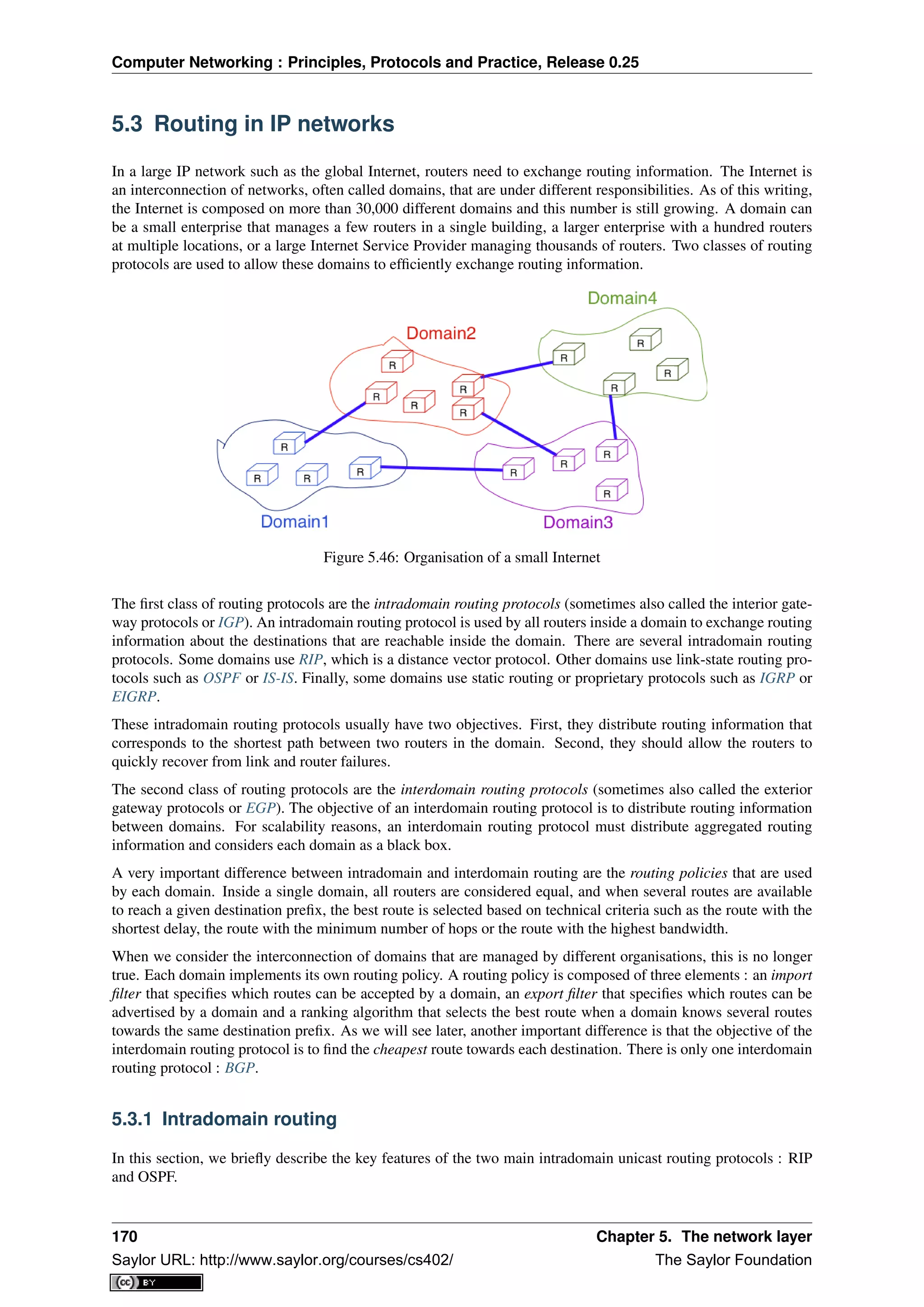
![Computer Networking : Principles, Protocols and Practice, Release 0.25
RIP
The Routing Information Protocol (RIP) is the simplest routing protocol that was standardised for the TCP/IP
protocol suite. RIP is defined in RFC 2453. Additional information about RIP may be found in [Malkin1999]
RIP routers periodically exchange RIP messages. The format of these messages is shown below. A RIP message
is sent inside a UDP segment whose destination port is set to 521. A RIP message contains several fields. The
Cmd field indicates whether the RIP message is a request or a response. Routers send one of more RIP response
messages every 30 seconds. These messages contain the distance vectors that summarize the router’s routing table.
The RIP request messages can be used by routers or hosts to query other routers about the content of their routing
table. A typical usage is when a router boots and quickly wants to receive the RIP responses from its neighbours
to compute its own routing table. The current version of RIP is version 2 defined in RFC 2453 for IPv4 and RFC
2080 for IPv6.
Figure 5.47: RIP message format
The RIP header contains an authentication field. This authentication can be used by network administrators to
ensure that only the RIP messages sent by the routers that they manage are used to build the routing tables. RFC
2453 only supports a basic authentication scheme where all routers are configured with the same password and
include this password in all RIP messages. This is not very secure since an attacker can know the password
by capturing a single RIP message. However, this password can protect against configuration errors. Stronger
authentication schemes are described in RFC 2082 and RFC 4822, but the details of these mechanisms are outside
the scope of this section.
Each RIP message contains a set of route entries. Each route entry is encoded as a 20 bytes field whose format
is shown below. RIP was initially designed to be suitable for different network layer protocols. Some implemen-
tations of RIP were used in XNS or IPX networks. The first field of the RIP route entry is the Address Family
Identifier (AFI). This identifier indicates the type of address found in the route entry 22
. IPv4 uses AFI=1. The
other important fields of the route entry are the IPv4 prefix, the netmask that indicates the length of the subnet
identifier and is encoded as a 32 bits netmask and the metric. Although the metric is encoded as a 32 bits field, the
maximum RIP metric is 15 (for RIP, 16 = ∞)
Figure 5.48: Format of the RIP IPv4 route entries ( RFC 2453)
With a 20 bytes route entry, it was difficult to use the same format as above to support IPv6. Instead of defining a
variable length route entry format, the designers of RFC 2080 defined a new format that does not include an AFI
field. The format of the route entries used by RFC 2080 is shown below. Plen is the length of the subnet identifier
in bits and the metric is encoded as one byte. The maximum metric is still 15.
22 The Address Family Identifiers are maintained by IANA at http://www.iana.org/assignments/address-family-numbers/
5.3. Routing in IP networks 171
Saylor URL: http://www.saylor.org/courses/cs402/ The Saylor Foundation](https://image.slidesharecdn.com/computer-networking-principles-bonaventure-1-30-31-otc1-150825141809-lva1-app6891/75/Computer-networking-principles-bonaventure-1-30-31-otc1-175-2048.jpg)
![Computer Networking : Principles, Protocols and Practice, Release 0.25
Figure 5.49: Format of the RIP IPv6 route entries
Note: A note on timers
The first RIP implementations sent their distance vector exactly every 30 seconds. This worked well in most
networks, but some researchers noticed that routers were sometimes overloaded because they were processing
too many distance vectors at the same time [FJ1994]. They collected packet traces in these networks and found
that after some time the routers’ timers became synchronised, i.e. almost all routers were sending their distance
vectors at almost the same time. This synchronisation of the transmission times of the distance vectors caused
an overload on the routers’ CPU but also increased the convergence time of the protocol in some cases. This
was mainly due to the fact that all routers set their timers to the same expiration time after having processed the
received distance vectors. Sally Floyd and Van Jacobson proposed in [FJ1994] a simple solution to solve this
synchronisation problem. Instead of advertising their distance vector exactly after 30 seconds, a router should
send its next distance vector after a delay chosen randomly in the [15,45] interval RFC 2080. This randomisation
of the delays prevents the synchronisation that occurs with a fixed delay and is now a recommended practice for
protocol designers.
OSPF
Link-state routing protocols are used in IP networks. Open Shortest Path First (OSPF), defined in RFC 2328, is the
link state routing protocol that has been standardised by the IETF. The last version of OSPF, which supports IPv6,
is defined in RFC 5340. OSPF is frequently used in enterprise networks and in some ISP networks. However,
ISP networks often use the IS-IS link-state routing protocol [ISO10589] , which was developed for the ISO CLNP
protocol but was adapted to be used in IP RFC 1195 networks before the finalisation of the standardisation
of OSPF. A detailed analysis of ISIS and OSPF may be found in [BMO2006] and [Perlman2000]. Additional
information about OSPF may be found in [Moy1998].
Compared to the basics of link-state routing protocols that we discussed in section Link state routing, there are
some particularities of OSPF that are worth discussing. First, in a large network, flooding the information about
all routers and links to thousands of routers or more may be costly as each router needs to store all the information
about the entire network. A better approach would be to introduce hierarchical routing. Hierarchical routing
divides the network into regions. All the routers inside a region have detailed information about the topology of
the region but only learn aggregated information about the topology of the other regions and their interconnections.
OSPF supports a restricted variant of hierarchical routing. In OSPF’s terminology, a region is called an area.
OSPF imposes restrictions on how a network can be divided into areas. An area is a set of routers and links that
are grouped together. Usually, the topology of an area is chosen so that a packet sent by one router inside the area
can reach any other router in the area without leaving the area 23
. An OSPF area contains two types of routers
RFC 2328:
• Internal router : A router whose directly connected networks belong to the area
• Area border routers : A router that is attached to several areas.
For example, the network shown in the figure below has been divided into three areas : area 1, containing routers
R1, R3, R4, R5 and RA, area 2 containing R7, R8, R9, R10, RB and RC. OSPF areas are identified by a 32 bit
integer, which is sometimes represented as an IP address. Among the OSPF areas, area 0, also called the backbone
area has a special role. The backbone area groups all the area border routers (routers RA, RB and RC in the figure
below) and the routers that are directly connected to the backbone routers but do not belong to another area (router
23 OSPF can support virtual links to connect routers together that belong to the same area but are not directly connected. However, this goes
beyond this introduction to OSPF.
172 Chapter 5. The network layer
Saylor URL: http://www.saylor.org/courses/cs402/ The Saylor Foundation](https://image.slidesharecdn.com/computer-networking-principles-bonaventure-1-30-31-otc1-150825141809-lva1-app6891/75/Computer-networking-principles-bonaventure-1-30-31-otc1-176-2048.jpg)
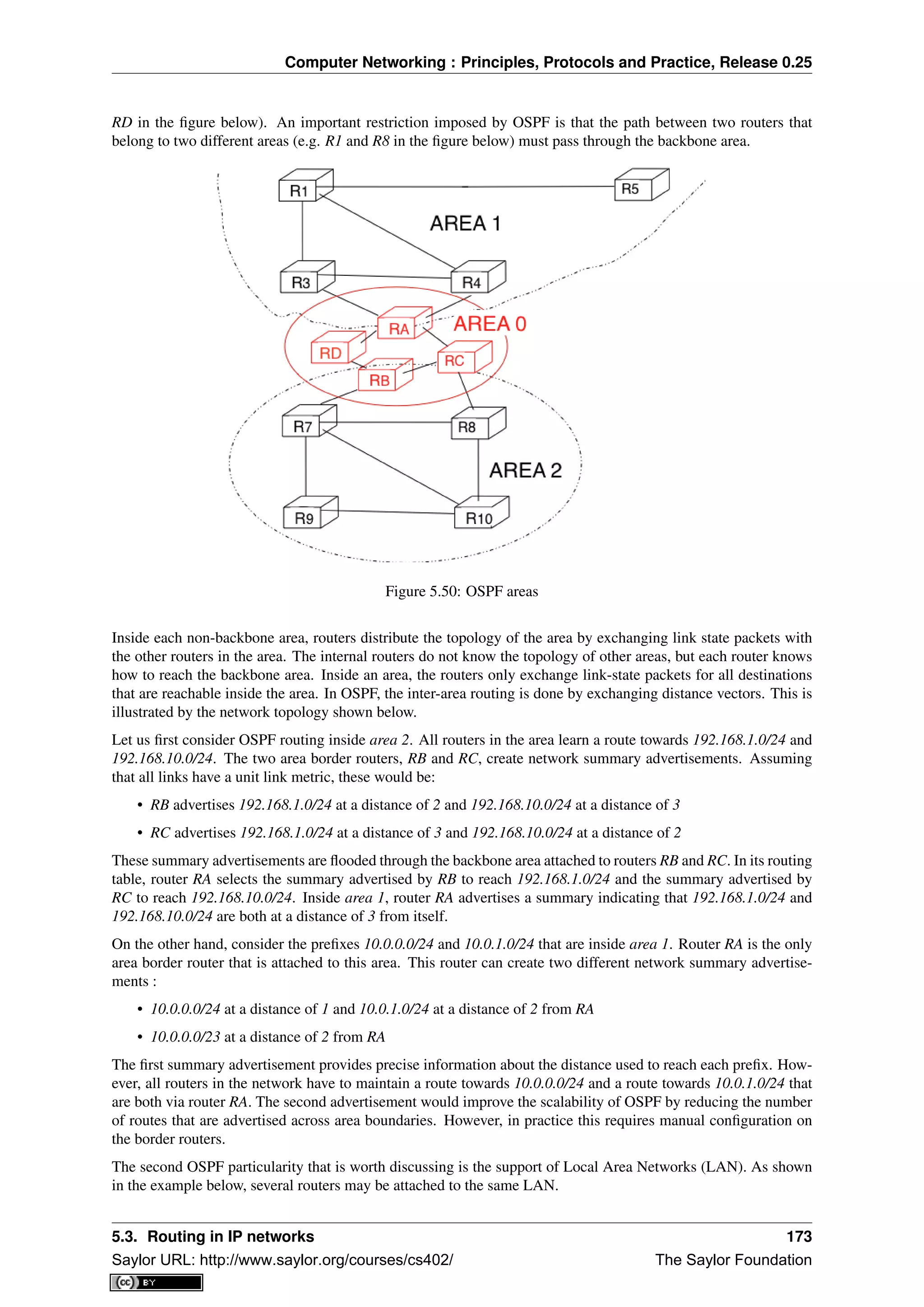
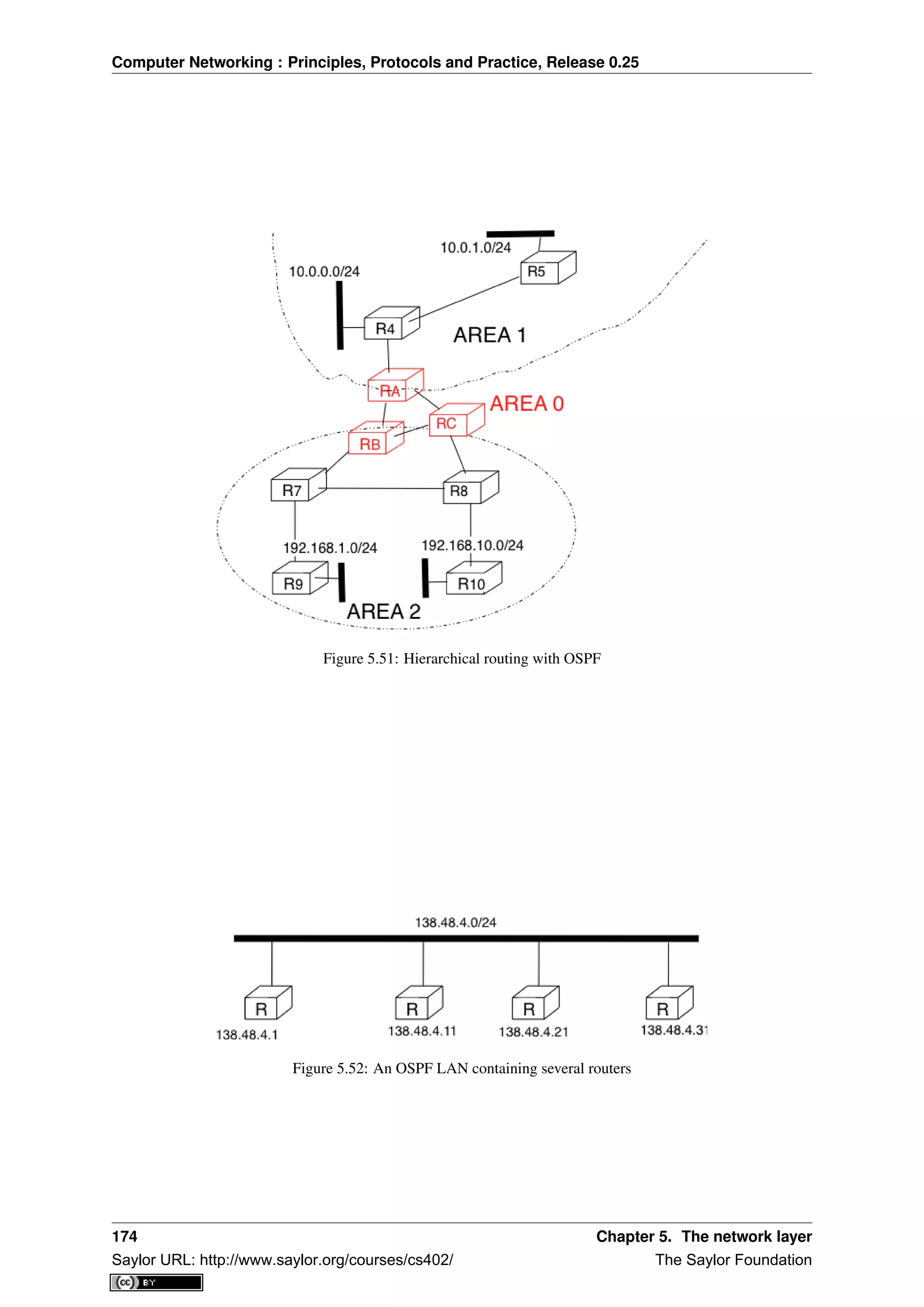
![Computer Networking : Principles, Protocols and Practice, Release 0.25
A first solution to support such a LAN with a link-state routing protocol would be to consider that a LAN is
equivalent to a full-mesh of point-to-point links as if each router can directly reach any other router on the LAN.
However, this approach has two important drawbacks :
1. Each router must exchange HELLOs and link state packets with all the other routers on the LAN. This
increases the number of OSPF packets that are sent and processed by each router.
2. Remote routers, when looking at the topology distributed by OSPF, consider that there is a full-mesh of
links between all the LAN routers. Such a full-mesh implies a lot of redundancy in case of failure, while in
practice the entire LAN may completely fail. In case of a failure of the entire LAN, all routers need to detect
the failures and flood link state packets before the LAN is completely removed from the OSPF topology by
remote routers.
To better represent LANs and reduce the number of OSPF packets that are exchanged, OSPF handles LAN differ-
ently. When OSPF routers boot on a LAN, they elect 24
one of them as the Designated Router (DR) RFC 2328.
The DR router represents the local area network, and advertises the LAN’s subnet (138.48.4.0/24 in the example
above). Furthermore, LAN routers only exchange HELLO packets with the DR. Thanks to the utilisation of a DR,
the topology of the LAN appears as a set of point-to-point links connected to the DR as shown in the figure below.
Figure 5.53: OSPF representation of a LAN
Note: How to quickly detect a link failure ?
Network operators expect an OSPF network to be able to quickly recover from link or router failures [VPD2004].
In an OSPF network, the recovery after a failure is performed in three steps [FFEB2005] :
• the routers that are adjacent to the failure detect it quickly. The default solution is to rely on the regular
exchange of HELLO packets. However, the interval between successive HELLOs is often set to 10 sec-
onds... Setting the HELLO timer down to a few milliseconds is difficult as HELLO packets are created and
processed by the main CPU of the routers and these routers cannot easily generate and process a HELLO
packet every millisecond on each of their interfaces. A better solution is to use a dedicated failure detection
protocol such as the Bidirectional Forwarding Detection (BFD) protocol defined in [KW2009] that can be
implemented directly on the router interfaces. Another solution to be able to detect the failure is to instru-
ment the physical and the datalink layer so that they can interrupt the router when a link fails. Unfortunately,
such a solution cannot be used on all types of physical and datalink layers.
• the routers that have detected the failure flood their updated link state packets in the network
• all routers update their routing table
5.3.2 Interdomain routing
As explained earlier, the Internet is composed of more than 30,000 different networks 25
called domains. Each
domain is composed of a group of routers and hosts that are managed by the same organisation. Example domains
include belnet, sprint, level3, geant, abilene, cisco or google ...
24 The OSPF Designated Router election procedure is defined in RFC 2328. Each router can be configured with a router priority that
influences the election process since the router with the highest priority is preferred when an election is run.
25 An analysis of the evolution of the number of domains on the global Internet during the last ten years may be found in
http://www.potaroo.net/tools/asn32/
5.3. Routing in IP networks 175
Saylor URL: http://www.saylor.org/courses/cs402/ The Saylor Foundation](https://image.slidesharecdn.com/computer-networking-principles-bonaventure-1-30-31-otc1-150825141809-lva1-app6891/75/Computer-networking-principles-bonaventure-1-30-31-otc1-179-2048.jpg)
![Computer Networking : Principles, Protocols and Practice, Release 0.25
Each domain contains a set of routers. From a routing point of view, these domains can be divided into two
classes : the transit and the stub domains. A stub domain sends and receives packets whose source or destination
are one of its own hosts. A transit domain is a domain that provides a transit service for other domains, i.e. the
routers in this domain forward packets whose source and destination do not belong to the transit domain. As of
this writing, about 85% of the domains in the Internet are stub domains 26
. A stub domain that is connected to a
single transit domain is called a single-homed stub. A multihomed stub is a stub domain connected to two or more
transit providers.
Figure 5.54: Transit and stub domains
The stub domains can be further classified by considering whether they mainly send or receive packets. An access-
rich stub domain is a domain that contains hosts that mainly receive packets. Typical examples include small
ADSL- or cable modem-based Internet Service Providers or enterprise networks. On the other hand, a content-
rich stub domain is a domain that mainly produces packets. Examples of content-rich stub domains include google,
yahoo, microsoft, facebook or content distribution networks such as akamai or limelight For the last few years, we
have seen a rapid growth of these content-rich stub domains. Recent measurements [ATLAS2009] indicate that a
growing fraction of all the packets exchanged on the Internet are produced in the data centers managed by these
content providers.
Domains need to be interconnected to allow a host inside a domain to exchange IP packets with hosts located
in other domains. From a physical perspective, domains can be interconnected in two different ways. The first
solution is to directly connect a router belonging to the first domain with a router inside the second domain. Such
links between domains are called private interdomain links or private peering links. In practice, for redundancy or
performance reasons, distinct physical links are usually established between different routers in the two domains
that are interconnected.
Figure 5.55: Interconnection of two domains via a private peering link
Such private peering links are useful when, for example, an enterprise or university network needs to be connected
to its Internet Service Provider. However, some domains are connected to hundreds of other domains 27
. For some
of these domains, using only private peering links would be too costly. A better solution to allow many domains
to interconnect cheaply are the Internet eXchange Points (IXP). An IXP is usually some space in a data center that
hosts routers belonging to different domains. A domain willing to exchange packets with other domains present
at the IXP installs one of its routers on the IXP and connects it to other routers inside its own network. The IXP
contains a Local Area Network to which all the participating routers are connected. When two domains that are
present at the IXP wish 28
to exchange packets, they simply use the Local Area Network. IXPs are very popular
26 Several web sites collect and analyse data about the evolution of BGP in the global Internet. http://bgp.potaroo.net provides lots of
statistics and analyses that are updated daily.
27 See http://as-rank.caida.org/ for an analysis of the interconnections between domains based on measurements collected in the global
Internet
28 Two routers that are attached to the same IXP only exchange packets when the owners of their domains have an economical incentive to
exchange packets on this IXP. Usually, a router on an IXP is only able to exchange packets with a small fraction of the routers that are present
on the same IXP.
176 Chapter 5. The network layer
Saylor URL: http://www.saylor.org/courses/cs402/ The Saylor Foundation](https://image.slidesharecdn.com/computer-networking-principles-bonaventure-1-30-31-otc1-150825141809-lva1-app6891/75/Computer-networking-principles-bonaventure-1-30-31-otc1-180-2048.jpg)
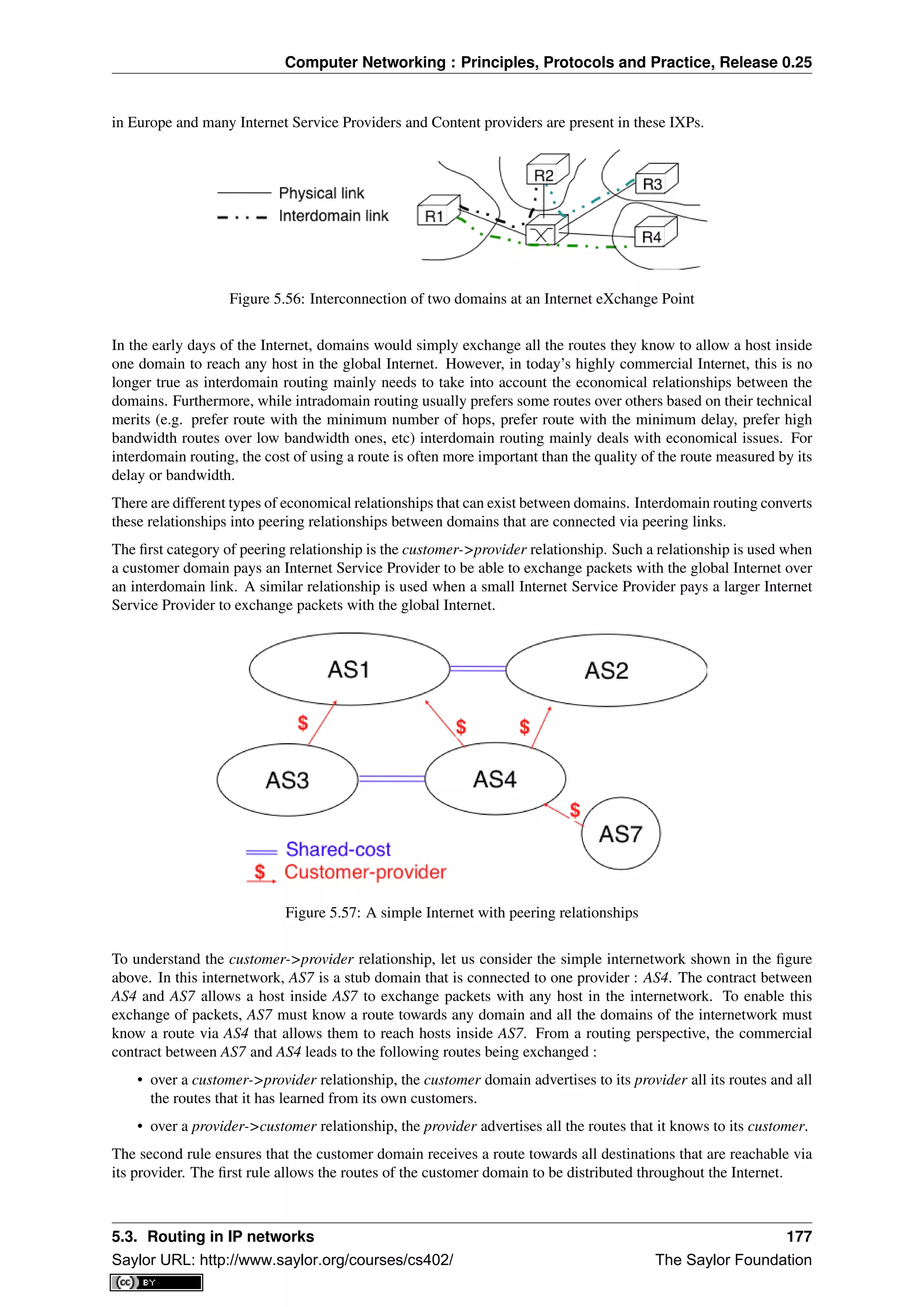
![Computer Networking : Principles, Protocols and Practice, Release 0.25
Coming back to the figure above, AS4 advertises to its two providers AS1 and AS2 its own routes and the routes
learned from its customer, AS7. On the other hand, AS4 advertises to AS7 all the routes that it knows.
The second type of peering relationship is the shared-cost peering relationship. Such a relationship usually does
not involve a payment from one domain to the other in contrast with the customer->provider relationship. A
shared-cost peering relationship is usually established between domains having a similar size and geographic
coverage. For example, consider the figure above. If AS3 and AS4 exchange many packets via AS1, they both need
to pay AS1. A cheaper alternative for AS3 and AS4 would be to establish a shared-cost peering. Such a peering
can be established at IXPs where both AS3 and AS4 are present or by using private peering links. This shared-cost
peering should be used to exchange packets between hosts inside AS3 and hosts inside AS4. However, AS3 does
not want to receive on the AS3-AS4 shared-cost peering links packets whose destination belongs to AS1 as AS3
would have to pay to send these packets to AS1.
From a routing perspective, over a shared-cost peering relationship a domain only advertises its internal routes
and the routes that it has learned from its customers. This restriction ensures that only packets destined to the
local domain or one of its customers is received over the shared-cost peering relationship. This implies that the
routes that have been learned from a provider or from another shared-cost peer is not advertised over a shared-cost
peering relationship. This is motivated by economical reasons. If a domain were to advertise the routes that it
learned from a provider over a shared-cost peering relationship that does not bring revenue, it would have allowed
its shared-cost peer to use the link with its provider without any payment. If a domain were to advertise the routes
it learned over a shared cost peering over another shared-cost peering relationship, it would have allowed these
shared-cost peers to use its own network (which may span one or more continents) freely to exchange packets.
Finally, the last type of peering relationship is the sibling. Such a relationship is used when two domains exchange
all their routes in both directions. In practice, such a relationship is only used between domains that belong to the
same company.
These different types of relationships are implemented in the interdomain routing policies defined by each domain.
The interdomain routing policy of a domain is composed of three main parts :
• the import filter that specifies, for each peering relationship, the routes that can be accepted from the neigh-
bouring domain (the non-acceptable routes are ignored and the domain never uses them to forward packets)
• the export filter that specifies, for each peering relationship, the routes that can be advertised to the neigh-
bouring domain
• the ranking algorithm that is used to select the best route among all the routes that the domain has received
towards the same destination prefix
A domain’s import and export filters can be defined by using the Route Policy Specification Language (RPSL)
specified in RFC 2622 [GAVE1999] . Some Internet Service Providers, notably in Europe, use RPSL to document
29
their import and export policies. Several tools help to easily convert a RPSL policy into router commands.
The figure below provides a simple example of import and export filters for two domains in a simple internetwork.
In RPSL, the keyword ANY is used to replace any route from any domain. It is typically used by a provider to
indicate that it announces all its routes to a customer over a provider->customer relationship. This is the case
for AS4‘s export policy. The example below clearly shows the difference between a provider->customer and a
shared-cost peering relationship. AS4‘s export filter indicates that it announces only its internal routes (AS4) and
the routes learned from its clients (AS7) over its shared-cost peering with AS3, while it advertises all the routes
that it uses (including the routes learned from AS3) to AS7.
The Border Gateway Protocol
The Internet uses a single interdomain routing protocol : the Border Gateway Protocol (BGP). The current ver-
sion of BGP is defined in RFC 4271. BGP differs from the intradomain routing protocols that we have already
discussed in several ways. First, BGP is a path-vector protocol. When a BGP router advertises a route towards a
prefix, it announces the IP prefix and the interdomain path used to reach this prefix. From BGP’s point of view,
each domain is identified by a unique Autonomous System (AS) number 30
and the interdomain path contains the
AS numbers of the transit domains that are used to reach the associated prefix. This interdomain path is called the
29 See ftp://ftp.ripe.net/ripe/dbase for the RIPE database that contains the import and export policies of many European ISPs
30 In this text, we consider Autonomous System and domain as synonyms. In practice, a domain may be divided into several Autonomous
Systems, but we ignore this detail.
178 Chapter 5. The network layer
Saylor URL: http://www.saylor.org/courses/cs402/ The Saylor Foundation](https://image.slidesharecdn.com/computer-networking-principles-bonaventure-1-30-31-otc1-150825141809-lva1-app6891/75/Computer-networking-principles-bonaventure-1-30-31-otc1-182-2048.jpg)
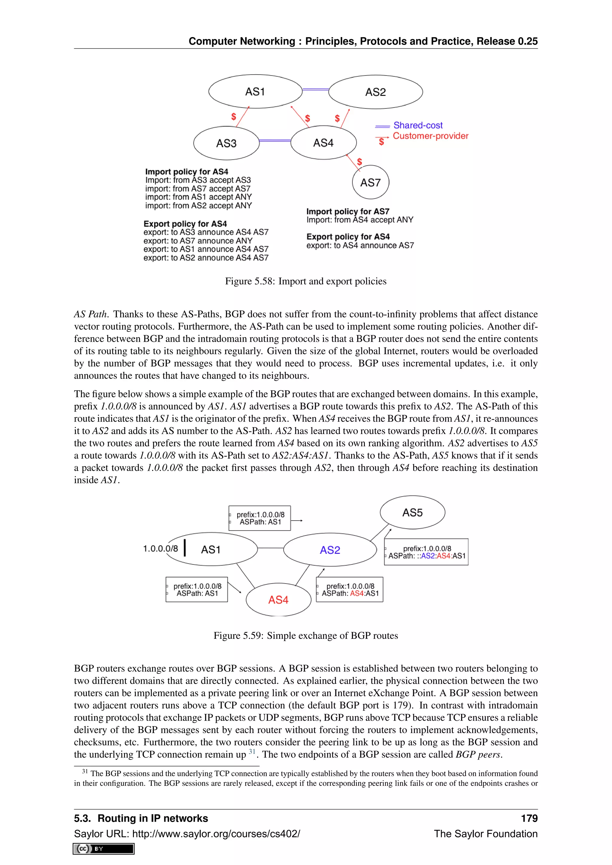
![Computer Networking : Principles, Protocols and Practice, Release 0.25
R1
R2
AS3
AS4
BGP
session
Figure 5.60: A BGP peering session between two directly connected routers
In practice, to establish a BGP session between routers R1 and R2 in the figure above, the network administrator
of AS3 must first configure on R1 the IP address of R2 on the R1-R2 link and the AS number of R2. Router R1 then
regularly tries to establish the BGP session with R2. R2 only agrees to establish the BGP session with R1 once it
has been configured with the IP address of R1 and its AS number. For security reasons, a router never establishes
a BGP session that has not been manually configured on the router.
The BGP protocol RFC 4271 defines several types of messages that can be exchanged over a BGP session :
• OPEN : this message is sent as soon as the TCP connection between the two routers has been established.
It initialises the BGP session and allows the negotiation of some options. Details about this message may
be found in RFC 4271
• NOTIFICATION : this message is used to terminate a BGP session, usually because an error has been de-
tected by the BGP peer. A router that sends or receives a NOTIFICATION message immediately shutdowns
the corresponding BGP session.
• UPDATE: this message is used to advertise new or modified routes or to withdraw previously advertised
routes.
• KEEPALIVE : this message is used to ensure a regular exchange of messages on the BGP session, even
when no route changes. When a BGP router has not sent an UPDATE message during the last 30 seconds,
it shall send a KEEPALIVE message to confirm to the other peer that it is still up. If a peer does not receive
any BGP message during a period of 90 seconds 32
, the BGP session is considered to be down and all the
routes learned over this session are withdrawn.
As explained earlier, BGP relies on incremental updates. This implies that when a BGP session starts, each router
first sends BGP UPDATE messages to advertise to the other peer all the exportable routes that it knows. Once
all these routes have been advertised, the BGP router only sends BGP UPDATE messages about a prefix if the
route is new, one of its attributes has changed or the route became unreachable and must be withdrawn. The BGP
UPDATE message allows BGP routers to efficiently exchange such information while minimising the number of
bytes exchanged. Each UPDATE message contains :
• a list of IP prefixes that are withdrawn
• a list of IP prefixes that are (re-)advertised
• the set of attributes (e.g. AS-Path) associated to the advertised prefixes
In the remainder of this chapter, and although all routing information is exchanged using BGP UPDATE messages,
we assume for simplicity that a BGP message contains only information about one prefix and we use the words :
• Withdraw message to indicate a BGP UPDATE message containing one route that is withdrawn
• Update message to indicate a BGP UPDATE containing a new or updated route towards one destination
prefix with its attributes
needs to be rebooted.
32 90 seconds is the default delay recommended by RFC 4271. However, two BGP peers can negotiate a different timer during the
establishment of their BGP session. Using a too small interval to detect BGP session failures is not recommended. BFD [KW2009] can be
used to replace BGP’s KEEPALIVE mechanism if fast detection of interdomain link failures is required.
180 Chapter 5. The network layer
Saylor URL: http://www.saylor.org/courses/cs402/ The Saylor Foundation](https://image.slidesharecdn.com/computer-networking-principles-bonaventure-1-30-31-otc1-150825141809-lva1-app6891/75/Computer-networking-principles-bonaventure-1-30-31-otc1-184-2048.jpg)
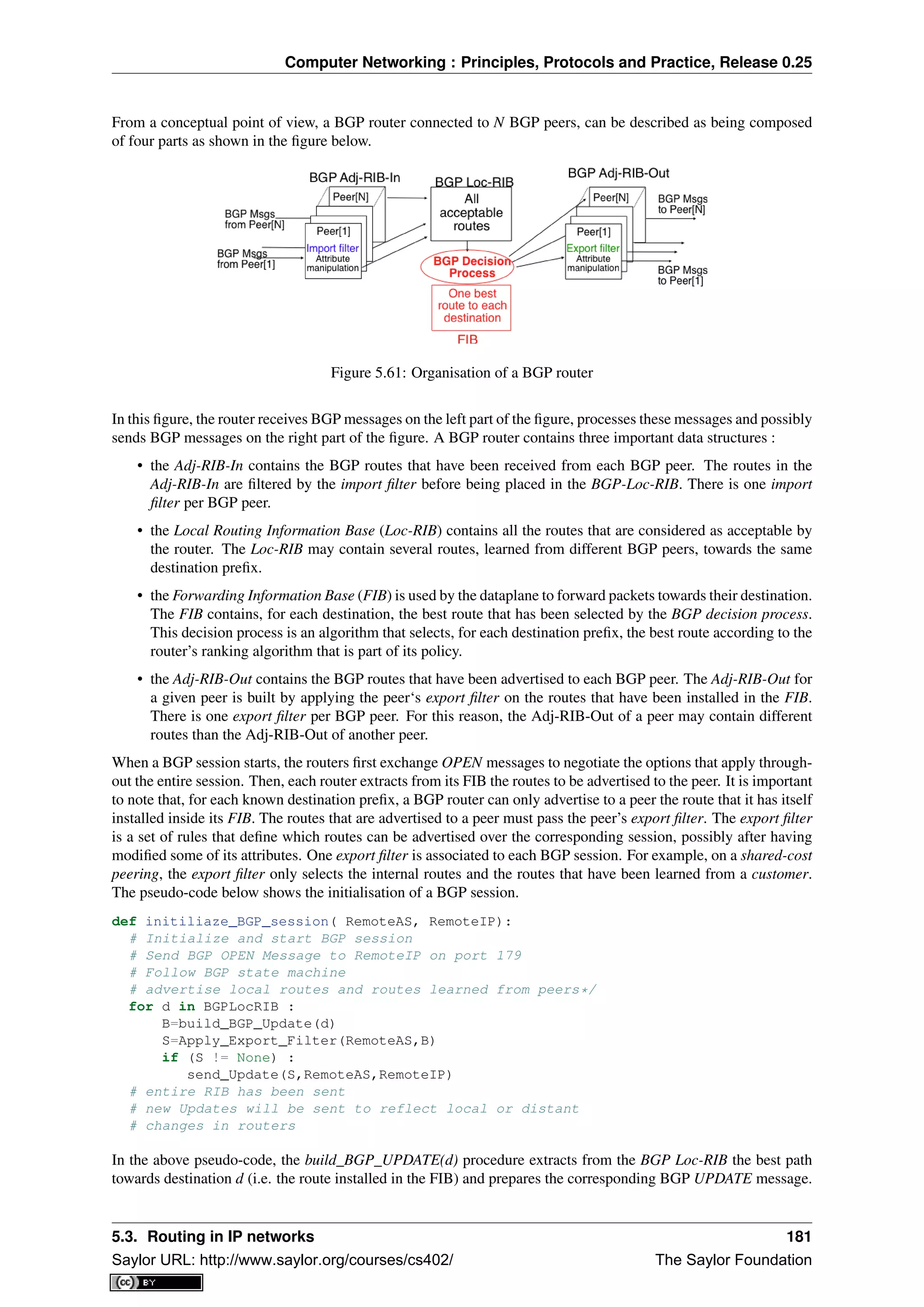
![Computer Networking : Principles, Protocols and Practice, Release 0.25
This message is then passed to the export filter that returns NULL if the route cannot be advertised to the peer or
the (possibly modified) BGP UPDATE message to be advertised. BGP routers allow network administrators to
specify very complex export filters, see e.g. [WMS2004]. A simple export filter that implements the equivalent of
split horizon is shown below.
def apply_export_filter(RemoteAS, BGPMsg) :
# check if RemoteAS already received route
if RemoteAS is BGPMsg.ASPath :
BGPMsg=None
# Many additional export policies can be configured :
# Accept or refuse the BGPMsg
# Modify selected attributes inside BGPMsg
return BGPMsg
At this point, the remote router has received all the exportable BGP routes. After this initial exchange, the router
only sends BGP UPDATE messages when there is a change (addition of a route, removal of a route or change in
the attributes of a route) in one of these exportable routes. Such a change can happen when the router receives a
BGP message. The pseudo-code below summarizes the processing of these BGP messages.
def Recvd_BGPMsg(Msg, RemoteAS) :
B=apply_import_filer(Msg,RemoteAS)
if (B== None): # Msg not acceptable
return
if IsUPDATE(Msg):
Old_Route=BestRoute(Msg.prefix)
Insert_in_RIB(Msg)
Run_Decision_Process(RIB)
if (BestRoute(Msg.prefix) != Old_Route) :
# best route changed
B=build_BGP_Message(Msg.prefix);
S=apply_export_filter(RemoteAS,B);
if (S!=None) : # announce best route
send_UPDATE(S,RemoteAS,RemoteIP);
else if (Old_Route != None) :
send_WITHDRAW(Msg.prefix,RemoteAS, RemoteIP)
else : # Msg is WITHDRAW
Old_Route=BestRoute(Msg.prefix)
Remove_from_RIB(Msg)
Run_Decision_Process(RIB)
if (Best_Route(Msg.prefix) !=Old_Route):
# best route changed
B=build_BGP_Message(Msg.prefix)
S=apply_export_filter(RemoteAS,B)
if (S != None) : # still one best route towards Msg.prefix
send_UPDATE(S,RemoteAS, RemoteIP);
else if(Old_Route != None) : # No best route anymore
send_WITHDRAW(Msg.prefix,RemoteAS,RemoteIP);
When a BGP message is received, the router first applies the peer’s import filter to verify whether the message is
acceptable or not. If the message is not acceptable, the processing stops. The pseudo-code below shows a simple
import filter. This import filter accepts all routes, except those that already contain the local AS in their AS-Path.
If such a route was used, it would cause a routing loop. Another example of an import filter would be a filter used
by an Internet Service Provider on a session with a customer to only accept routes towards the IP prefixes assigned
to the customer by the provider. On real routers, import filters can be much more complex and some import filters
modify the attributes of the received BGP UPDATE [WMS2004] .
def apply_import_filter(RemoteAS, BGPMsg):
if MysAS in BGPMsg.ASPath :
BGPMsg=None
# Many additional import policies can be configured :
# Accept or refuse the BGPMsg
# Modify selected attributes inside BGPMsg
return BGPMsg
182 Chapter 5. The network layer
Saylor URL: http://www.saylor.org/courses/cs402/ The Saylor Foundation](https://image.slidesharecdn.com/computer-networking-principles-bonaventure-1-30-31-otc1-150825141809-lva1-app6891/75/Computer-networking-principles-bonaventure-1-30-31-otc1-186-2048.jpg)
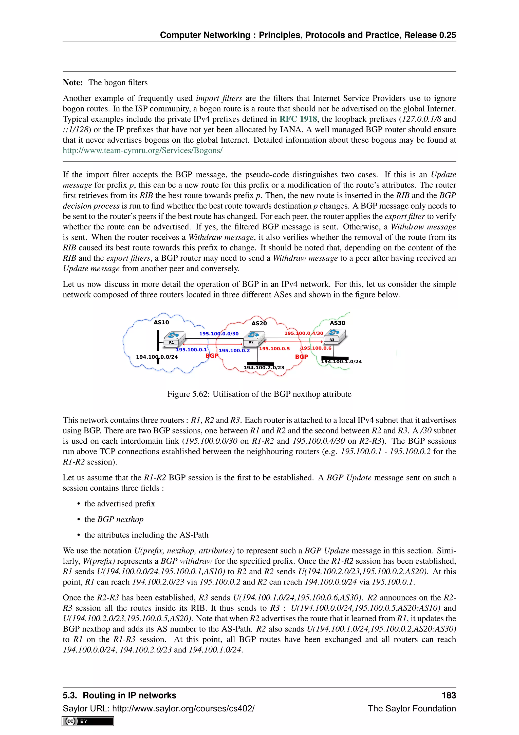
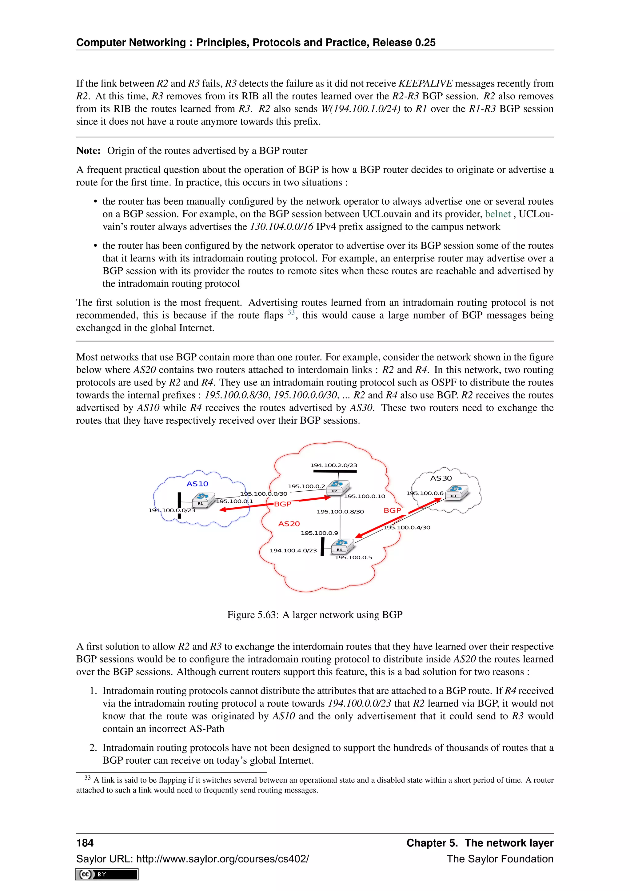
![Computer Networking : Principles, Protocols and Practice, Release 0.25
The best solution to allow BGP routers to distribute, inside an AS, all the routes learned over BGP sessions is to
establish BGP sessions among all the BGP routers inside the AS. In practice, there are two types of BGP sessions
:
• eBGP session or external BGP session. Such a BGP session is established between two routers that are
directly connected and belong to two different domains.
• iBGP session or internal BGP session. Such a BGP session is established between two routers belonging to
the same domain. These two routers do not need to be directly connected.
In practice, each BGP router inside a domain maintains an iBGP session with every other BGP router in the
domain 34
. This creates a full-mesh of iBGP sessions among all BGP routers of the domain. iBGP sessions, like
eBGP sessions run over TCP connections. Note that in contrast with eBGP sessions that are established between
directly connected routers, iBGP sessions are often established between routers that are not directly connected.
An important point to note about iBGP sessions is that a BGP router only advertises a route over an iBGP session
provided that :
• the router uses this route to forward packets, and
• the route was learned over one of the router’s eBGP sessions
A BGP router does not advertise a route that it has learned over an iBGP session over another iBGP session. Note
that a router can, of course, advertise over an eBGP session a route that it has learned over an iBGP session.
This difference between the behaviour of a BGP router over iBGP and eBGP session is due to the utilisation of a
full-mesh of iBGP sessions. Consider a network containing three BGP routers : A, B and C interconnected via a
full-mesh of iBGP sessions. If router A learns a route towards prefix p from router B, router A does not need to
advertise the received route to router C since router C also learns the same route over the C-B iBGP session.
To understand the utilisation of an iBGP session, let us consider what happens when router R1 sends
U(194.100.0.0/23,195.100.0.1,AS10) in the network shown below. This BGP message is processed by R2 which
advertises it over its iBGP session with R4. The BGP Update sent by R2 contains the same nexthop and the same
AS-Path as in the BGP Update received by R2. R4 then sends U(194.100.0.0/23,195.100.0.5,AS20:AS10) to R3.
Note that the BGP nexthop and the AS-Path are only updated 35
when a BGP route is advertised over an eBGP
session.
AS20
AS30AS10
194.100.2.0/23
195.100.0.1
195.100.0.2
195.100.0.6195.100.0.0/30
195.100.0.4/30
194.100.4.0/23
195.100.0.8/30
195.100.0.9
195.100.0.10
eBGP
eBGPiBGP
194.100.0.0/23
195.100.0.5
R1
R4
R2
R3
Figure 5.64: iBGP and eBGP sessions
Note: Loopback interfaces and iBGP sessions
In addition to their physical interfaces, routers can also be configured with a special loopback interface. A loop-
back interface is a software interface that is always up. When a loopback interface is configured on a router,
the address associated to this interface is advertised by the intradomain routing protocol. Consider for example
34 Using a full-mesh of iBGP sessions is suitable in small networks. However, this solution does not scale in large networks containing
hundreds or more routers since
n×(n−1)
2
iBGP sessions must be established in a domain containing n BGP routers. Large domains use either
Route Reflection RFC 4456 or confederations RFC 5065 to scale their iBGP, but this goes beyond this introduction.
35 Some routers, when they receive a BGP Update over an eBGP session, set the nexthop of the received route to one of their own addresses.
This is called nexthop-self. See e.g. [WMS2004] for additional details.
5.3. Routing in IP networks 185
Saylor URL: http://www.saylor.org/courses/cs402/ The Saylor Foundation](https://image.slidesharecdn.com/computer-networking-principles-bonaventure-1-30-31-otc1-150825141809-lva1-app6891/75/Computer-networking-principles-bonaventure-1-30-31-otc1-189-2048.jpg)
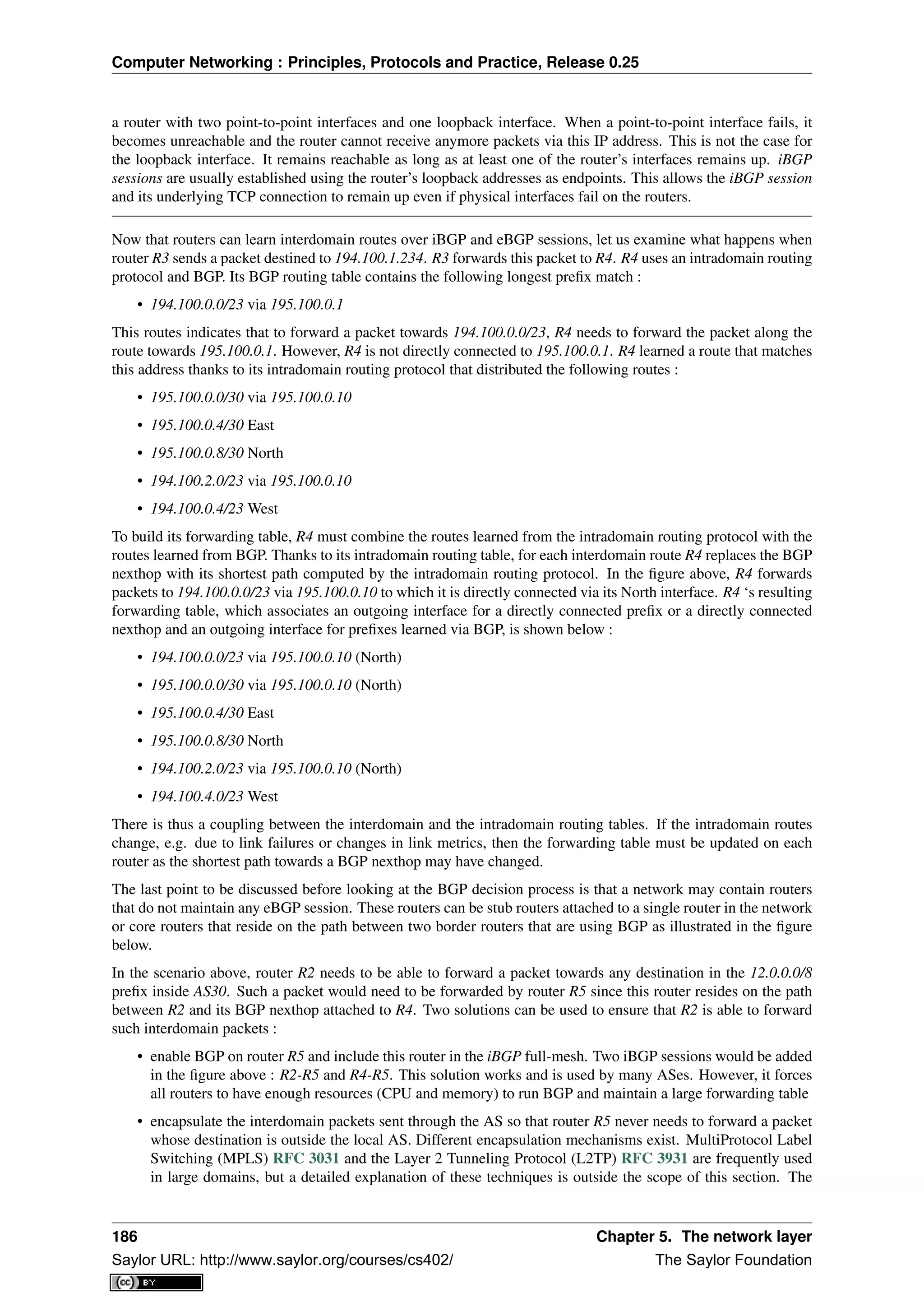
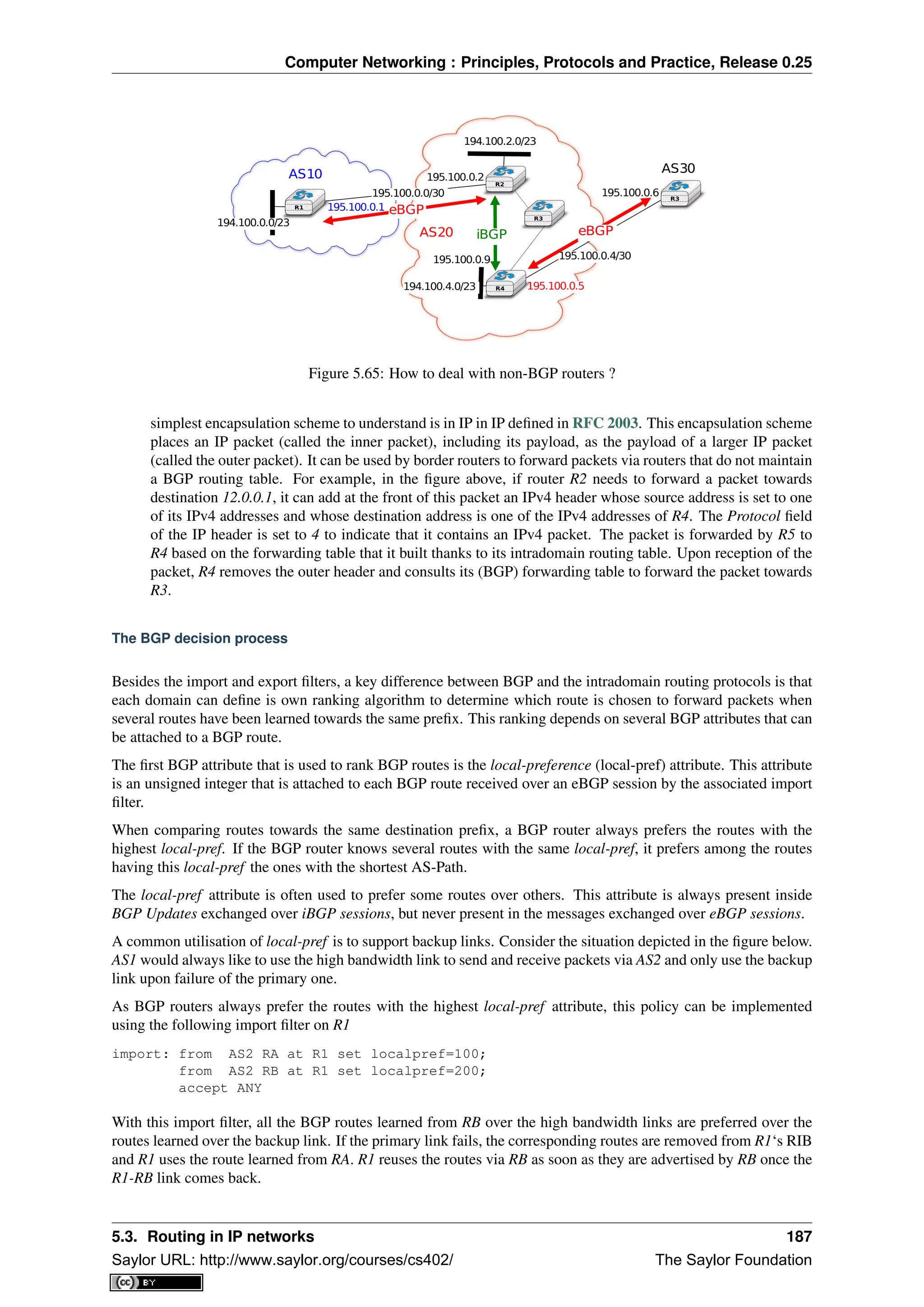
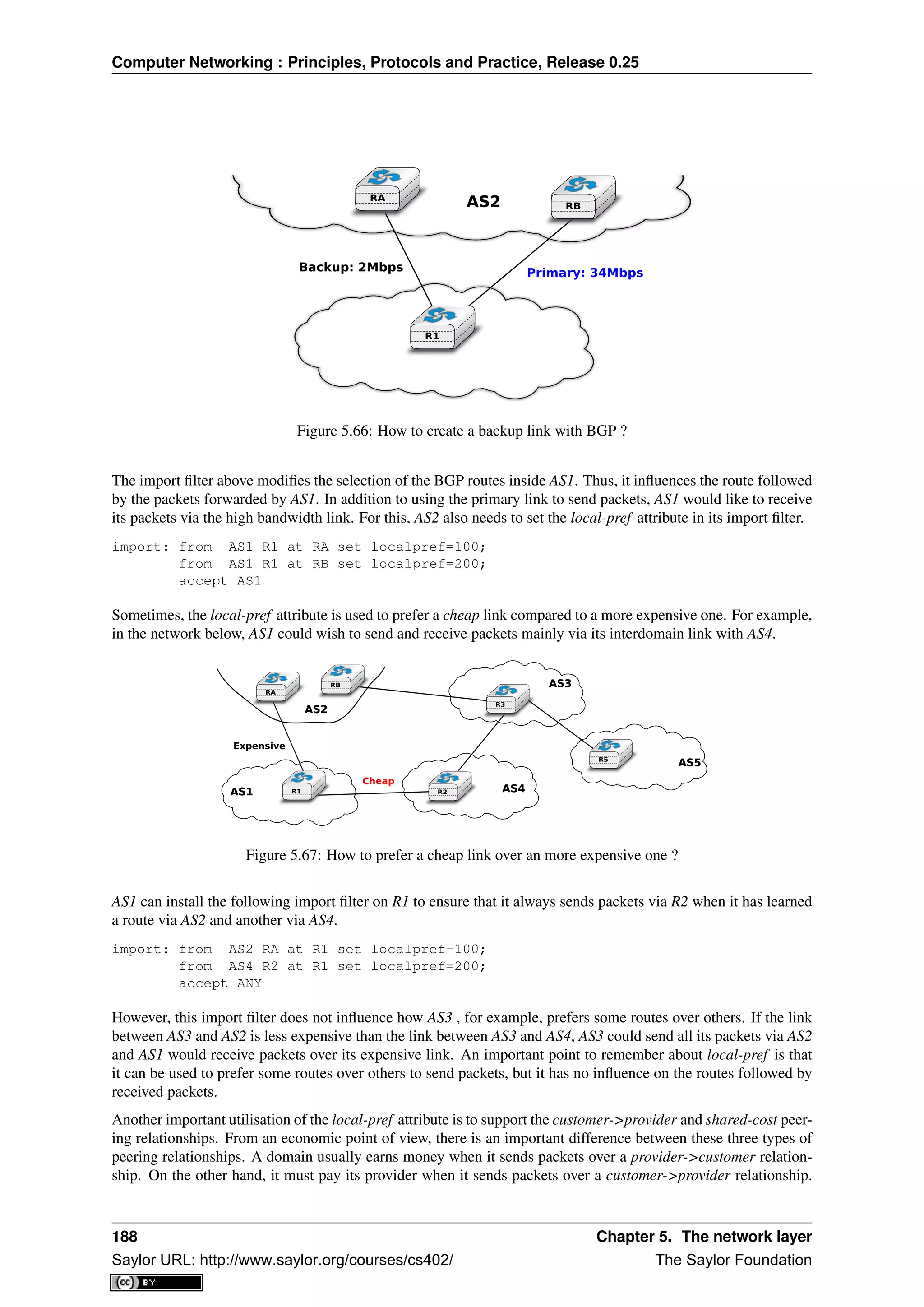
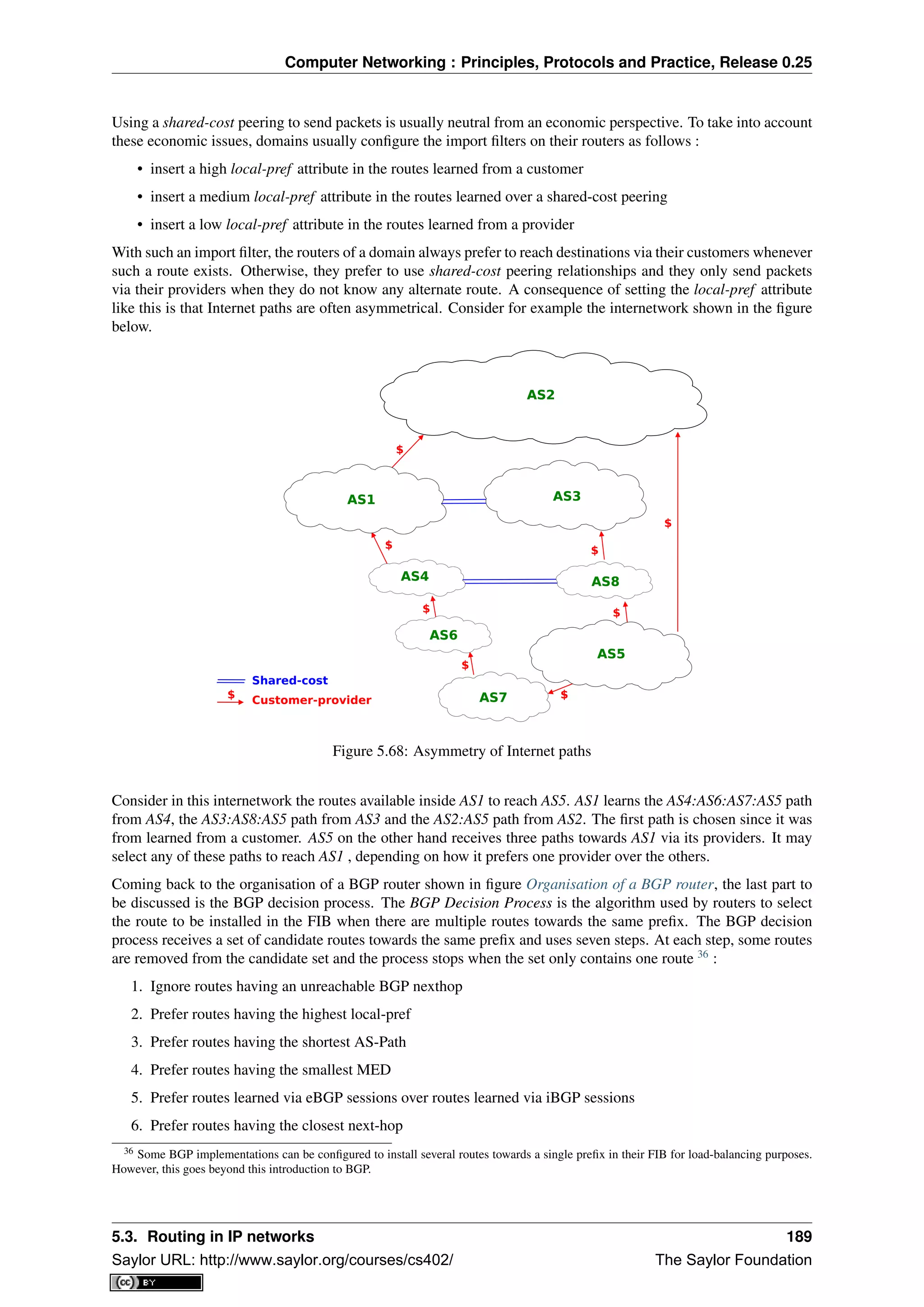
![Computer Networking : Principles, Protocols and Practice, Release 0.25
7. Tie breaking rules : prefer routes learned from the router with lowest router id
The first step of the BGP decision process ensures that a BGP router does not install in its FIB a route whose
nexthop is considered to be unreachable by the intradomain routing protocol. This could happen, for example,
when a router has crashed. The intradomain routing protocol usually advertises the failure of this router before
the failure of the BGP sessions that it terminates. This rule implies that the BGP decision process must be re-run
each time the intradomain routing protocol reports a change in the reachability of a prefix containing one of more
BGP nexthops.
The second rule allows each domain to define its routing preferences. The local-pref attribute is set by the import
filter of the router that learned a route over an eBGP session.
In contrast with intradomain routing protocols, BGP does not contain an explicit metric. This is because in the
global Internet it is impossible for all domains to agree on a common metric that meets the requirements of all
domains. Despite this, BGP routers prefer routes having a short AS-Path attribute over routes with a long AS-
Path. This step of the BGP decision process is motivated by the fact that operators expect that a route with a long
AS-Path is lower quality than a route with a shorter AS-Path. However, studies have shown that there was not
always a strong correlation between the quality of a route and the length of its AS-Path [HFPMC2002].
Before explaining the fourth step of the BGP decision process, let us first describe the fifth and the sixth steps of
the BGP decision process. These two steps are used to implement hot potato routing. Intuitively, when a domain
implements hot potato routing, it tries to forward packets that are destined to addresses outside of its domain, to
other domains as quickly as possible.
To understand hot potato routing, let us consider the two domains shown in the figure below. AS2 advertises prefix
1.0.0.0/8 over the R2-R6 and R3-R7 peering links. The routers inside AS1 learn two routes towards 1.0.0.0/8: one
via R6-R2 and the second via R7-R3.
R8
R6
R2
R3R0
R7
C=50
C=1 C=98
1.0.0.0/8
C=1
AS1AS1
AS2AS2
Figure 5.69: Hot and cold potato routing
With the fifth step of the BGP decision process, a router always prefers to use a route learned over an eBGP session
compared to a route learned over an iBGP session. Thus, router R6 (resp. R7) prefers to use the route via router
R2 (resp. R3) to reach prefix 1.0.0.0/8.
The sixth step of the BGP decision process takes into account the distance, measured as the length of the shortest
intradomain path, between a BGP router and the BGP nexthop for routes learned over iBGP sessions. This rule is
used on router R8 in the example above. This router has received two routes towards 1.0.0.0/8:
• 1.0.0.0/8 via R7 that is at a distance of 1 from R8
• 1.0.0.0/8 via R6 that is at a distance of 50 from R8
The first route, via R7 is the one that router R8 prefers, as this is the route that minimises the cost of forwarding
packets inside AS1 before sending them to AS2.
190 Chapter 5. The network layer
Saylor URL: http://www.saylor.org/courses/cs402/ The Saylor Foundation](https://image.slidesharecdn.com/computer-networking-principles-bonaventure-1-30-31-otc1-150825141809-lva1-app6891/75/Computer-networking-principles-bonaventure-1-30-31-otc1-194-2048.jpg)
![Computer Networking : Principles, Protocols and Practice, Release 0.25
Hot potato routing allows AS1 to minimise the cost of forwarding packets towards AS2. However, there are
situations where this is not desirable. For example, assume that AS1 and AS2 are domains with routers on both
the East and the West coast of the US. In these two domains, the high metric associated to links R6-R8 and R0-R2
correspond to the cost of forwarding a packet across the USA. If AS2 is a customer that pays AS1, it would prefer
to receive the packets destined to 1.0.0.0/8 via the R2-R6 link instead of the R7-R3 link. This is the objective of
cold potato routing.
Cold potato routing is implemented using the Multi-Exit Discriminator (MED) attribute. This attribute is an
optional BGP attribute that may be set 37
by border routers when advertising a BGP route over an eBGP session.
The MED attribute is usually used to indicate over an eBGP session the cost to reach the BGP nexthop for the
advertised route. The MED attribute is set by the router that advertises a route over an eBGP session. In the
example above, router R2 sends U(1.0.0.0/8,R2,AS2,MED=1) while R3 sends U(1.0.0.0/8,R3,AS2,MED=98).
Assume that the BGP session R7-3 is the first to be established. R7 sends U(1.0.0.0/8,R3,AS2,MED=98) to both
R8 and R6. At this point, all routers inside AS1 send the packets towards 1.0.0.0/8 via R7-R3. Then, the R6-
R2 BGP session is established and router R6 receives U(1.0.0.0/8,R2,AS2,MED=1). Router R6 runs its decision
process for destination 1.0.0.0/8 and selects the route via R2 as its chosen route to reach this prefix since this is the
only route that it knows. R6 sends U(1.0.0.0/8,R2,AS2,MED=1) to routers R8 and R7. They both run their decision
process and prefer the route advertised by R6, as it contains the smallest MED. Now, all routers inside AS1 forward
the packets to 1.0.0.0/8 via link R6-R2 as expected by AS2. As router R7 no longer uses the BGP route learned
via R3, it must stop advertising it over iBGP sessions and sends W(1.0.0.0/8) over its iBGP sessions with R6 and
R8. However, router R7 still keeps the route learned from R3 inside its Adj-RIB-In. If the R6-R2 link fails, R6
sends W(1.0.0.0/8) over its iBGP sessions and router R7 responds by sending U(1.0.0.0/8,R3,AS2,MED=98) over
its iBGP sessions.
In practice, the fifth step of the BGP decision process is slightly more complex, as the routes towards a given prefix
can be learned from different ASes. For example, assume that in figure Hot and cold potato routing, 1.0.0.0/8 is
also advertised by AS3 (not shown in the figure) that has peering links with routers R6 and R8. If AS3 advertises a
route whose MED attribute is set to 2 and another with a MED set to 3, how should AS1‘s router compare the four
BGP routes towards 1.0.0.0/8 ? Is a MED value of 1 from AS2 better than a MED value of 2 from AS3 ? The fifth
step of the BGP decision process solves this problem by only comparing the MED attribute of the routes learned
from the same neighbour AS. Additional details about the MED attribute may be found in RFC 4451. It should
be noted that using the MED attribute may cause some problems in BGP networks as explained in [GW2002]. In
practice, the MED attribute is not used on eBGP sessions unless the two domains agree to enable it.
The last step of the BGP decision allows the selection of a single route when a BGP router has received several
routes that are considered as equal by the first six steps of the decision process. This can happen for example
in a dual-homed stub attached to two different providers. As shown in the figure below, router R1 receives two
equally good BGP routes towards 1.0.0.0/8. To break the ties, each router is identified by a unique router-id which
in practice is one of the IP addresses assigned to the router. On some routers, the lowest router id step in the
BGP decision process is replaced by the selection of the oldest route RFC 5004. Preferring the oldest route when
breaking ties is used to prefer stable paths over unstable paths. However, a drawback of this approach is that the
selection of the BGP routes depends on the arrival times of the corresponding messages. This makes the BGP
selection process non-deterministic and can lead to problems that are difficult to debug.
R0
R2
R3
R1
1.0.0.0/8
AS2AS2
AS1AS1
AS3AS3
Figure 5.70: A stub connected to two providers
37 The MED attribute can be used on customer->provider peering relationships upon request of the customer. On shared-cost peering
relationship, the MED attribute is only enabled when there is a explicit agreement between the two peers.
5.3. Routing in IP networks 191
Saylor URL: http://www.saylor.org/courses/cs402/ The Saylor Foundation](https://image.slidesharecdn.com/computer-networking-principles-bonaventure-1-30-31-otc1-150825141809-lva1-app6891/75/Computer-networking-principles-bonaventure-1-30-31-otc1-195-2048.jpg)
![Computer Networking : Principles, Protocols and Practice, Release 0.25
BGP convergence
In the previous sections, we have explained the operation of BGP routers. Compared to intradomain routing
protocols, a key feature of BGP is its ability to support interdomain routing policies that are defined by each
domain as its import and export filters and ranking process. A domain can define its own routing policies and
router vendors have implemented many configuration tweaks to support complex routing policies. However, the
routing policy chosen by a domain may interfere with the routing policy chosen by another domain. To understand
this issue, let us first consider the simple internetwork shown below.
Preferred paths for AS3
1. AS4:AS1
2. AS1
Preferred paths for AS4
1. AS3:AS1
2. AS1
1.0.0.0/8
AS1AS1
AS3AS3 AS4AS4
Figure 5.71: The disagree internetwork
In this internetwork, we focus on the route towards 1.0.0.0/8 which is advertised by AS1. Let us also assume that
AS3 (resp. AS4) prefers, e.g. for economic reasons, a route learned from AS4 (AS3) over a route learned from AS1.
When AS1 sends U(1.0.0.0/8,AS1) to AS3 and AS4, three sequences of exchanges of BGP messages are possible :
1. AS3 sends first U(1.0.0.0/8,AS3:AS1) to AS4. AS4 has learned two routes towards 1.0.0.0/8. It runs its BGP
decision process and selects the route via AS3 and does not advertise a route to AS3
2. AS4 first sends U(1.0.0.0/8,AS3:AS1) to AS3. AS3 has learned two routes towards 1.0.0.0/8. It runs its BGP
decision process and selects the route via AS4 and does not advertise a route to AS4
3. AS3 sends U(1.0.0.0/8,AS3:AS1) to AS4 and, at the same time, AS4 sends U(1.0.0.0/8,AS4:AS1). AS3 prefers
the route via AS4 and thus sends W(1.0.0.0/8) to AS4. In the mean time, AS4 prefers the route via AS3 and
thus sends W(1.0.0.0/8) to AS3. Upon reception of the BGP Withdraws, AS3 and AS4 only know the direct
route towards 1.0.0.0/8. AS3 (resp. AS4) sends U(1.0.0.0/8,AS3:AS1) (resp. U(1.0.0.0/8,AS4:AS1)) to AS4
(resp. AS3). AS3 and AS4 could in theory continue to exchange BGP messages for ever. In practice, one of
them sends one message faster than the other and BGP converges.
The example above has shown that the routes selected by BGP routers may sometimes depend on the ordering of
the BGP messages that are exchanged. Other similar scenarios may be found in RFC 4264.
From an operational perspective, the above configuration is annoying since the network operators cannot easily
predict which paths are chosen. Unfortunately, there are even more annoying BGP configurations. For example,
let us consider the configuration below which is often named Bad Gadget [GW1999]
In this internetwork, there are four ASes. AS0 advertises one route towards one prefix and we only analyse the
routes towards this prefix. The routing preferences of AS1, AS3 and AS4 are the following :
• AS1 prefers the path AS3:AS0 over all other paths
• AS3 prefers the path AS4:AS0 over all other paths
• AS4 prefers the path AS1:AS0 over all other paths
AS0 sends U(p,AS0) to AS1, AS3 and AS4. As this is the only route known by AS1, AS3 and AS4 towards p, they
all select the direct path. Let us now consider one possible exchange of BGP messages :
1. AS1 sends U(p, AS1:AS0) to AS3 and AS4. AS4 selects the path via AS1 since this is its preferred path. AS3
still uses the direct path.
2. AS4 advertises U(p,AS4:AS1:AS0) to AS3.
192 Chapter 5. The network layer
Saylor URL: http://www.saylor.org/courses/cs402/ The Saylor Foundation](https://image.slidesharecdn.com/computer-networking-principles-bonaventure-1-30-31-otc1-150825141809-lva1-app6891/75/Computer-networking-principles-bonaventure-1-30-31-otc1-196-2048.jpg)
![Computer Networking : Principles, Protocols and Practice, Release 0.25
Preferred paths for AS3
1. AS4:AS0
2. other paths
Preferred paths for AS1
1. AS3:AS0
2. other paths
Preferred paths for AS4
1. AS1:AS0
2. other paths
AS1AS1
AS0AS0
AS3AS3 AS4AS4
Figure 5.72: The bad gadget internetwork
3. AS3 sends U(p, AS3:AS0) to AS1 and AS4. AS1 selects the path via AS3 since this is its preferred path. AS4
still uses the path via AS1.
4. As AS1 has changed its path, it sends U(p,AS1:AS3:AS0) to AS4 and W(p) to AS3 since its new path is via
AS3. AS4 switches back to the direct path.
5. AS4 sends U(p,AS4:AS0) to AS1 and AS3. AS3 prefers the path via AS4.
6. AS3 sends U(p,AS3:AS4:AS0) to AS1 and W(p) to AS4. AS1 switches back to the direct path and we are
back at the first step.
This example shows that the convergence of BGP is unfortunately not always guaranteed as some interdomain
routing policies may interfere with each other in complex ways. [GW1999] have shown that checking for global
convergence is either NP-complete or NP-hard. See [GSW2002] for a more detailed discussion.
Fortunately, there are some operational guidelines [GR2001] [GGR2001] that can guarantee BGP convergence in
the global Internet. To ensure that BGP will converge, these guidelines consider that there are two types of peering
relationships : customer->provider and shared-cost. In this case, BGP convergence is guaranteed provided that
the following conditions are fulfilled :
1. The topology composed of all the directed customer->provider peering links is an acyclic graph
2. An AS always prefers a route received from a customer over a route received from a shared-cost peer or a
provider.
The first guideline implies that the provider of the provider of ASx cannot be a customer of ASx. Such a relationship
would not make sense from an economic perspective as it would imply circular payments. Furthermore, providers
are usually larger than customers.
The second guideline also corresponds to economic preferences. Since a provider earns money when sending
packets to one of its customers, it makes sense to prefer such customer learned routes over routes learned from
providers. [GR2001] also shows that BGP convergence is guaranteed even if an AS associates the same preference
to routes learned from a shared-cost peer and routes learned from a customer.
From a theoretical perspective, these guidelines should be verified automatically to ensure that BGP will always
converge in the global Internet. However, such a verification cannot be performed in practice because this would
force all domains to disclose their routing policies (and few are willing to do so) and furthermore the problem is
known to be NP-hard [GW1999].
In practice, researchers and operators expect that these guidelines are verified 38
in most domains. Thanks to the
large amount of BGP data that has been collected by operators and researchers 39
, several studies have analysed
38 Some researchers such as [MUF+2007] have shown that modelling the Internet topology at the AS-level requires more than the shared-
cost and customer->provider peering relationships. However, there is no publicly available model that goes beyond these classical peering
relationships.
39 BGP data is often collected by establishing BGP sessions between Unix hosts running a BGP daemon and BGP routers in differ-
ent ASes. The Unix hosts stores all BGP messages received and regular dumps of its BGP routing table. See http://www.routeviews.org,
http://www.ripe.net/ris, http://bgp.potaroo.net or http://irl.cs.ucla.edu/topology/
5.3. Routing in IP networks 193
Saylor URL: http://www.saylor.org/courses/cs402/ The Saylor Foundation](https://image.slidesharecdn.com/computer-networking-principles-bonaventure-1-30-31-otc1-150825141809-lva1-app6891/75/Computer-networking-principles-bonaventure-1-30-31-otc1-197-2048.jpg)
![Computer Networking : Principles, Protocols and Practice, Release 0.25
the AS-level topology of the Internet. [SARK2002] is one of the first analysis. More recent studies include
[COZ2008] and [DKF+2007]
Based on these studies and [ATLAS2009], the AS-level Internet topology can be summarised as shown in the
figure below.
Figure 5.73: The layered structure of the global Internet
The domains on the Internet can be divided in about four categories according to their role and their position in
the AS-level topology.
• the core of the Internet is composed of a dozen-twenty Tier-1 ISPs. A Tier-1 is a domain that has no provider.
Such an ISP has shared-cost peering relationships with all other Tier-1 ISPs and provider->customer rela-
tionships with smaller ISPs. Examples of Tier-1 ISPs include sprint, level3 or opentransit
• the Tier-2 ISPs are national or continental ISPs that are customers of Tier-1 ISPs. These Tier-2 ISPs have
smaller customers and shared-cost peering relationships with other Tier-2 ISPs. Example of Tier-2 ISPs
include France Telecom, Belgacom, British Telecom, ...
• the Tier-3 networks are either stub domains such as enterprise or campus networks networks and smaller
ISPs. They are customers of Tier-1 and Tier-2 ISPs and have sometimes shared-cost peering relationships
• the large content providers that are managing large datacenters. These content providers are producing a
growing fraction of the packets exchanged on the global Internet [ATLAS2009]. Some of these content
providers are customers of Tier-1 or Tier-2 ISPs, but they often try to establish shared-cost peering relation-
ships, e.g. at IXPs, with many Tier-1 and Tier-2 ISPs.
Due to this organisation of the Internet and due to the BGP decision process, most AS-level paths on the Internet
have a length of 3-5 AS hops.
194 Chapter 5. The network layer
Saylor URL: http://www.saylor.org/courses/cs402/ The Saylor Foundation](https://image.slidesharecdn.com/computer-networking-principles-bonaventure-1-30-31-otc1-150825141809-lva1-app6891/75/Computer-networking-principles-bonaventure-1-30-31-otc1-198-2048.jpg)
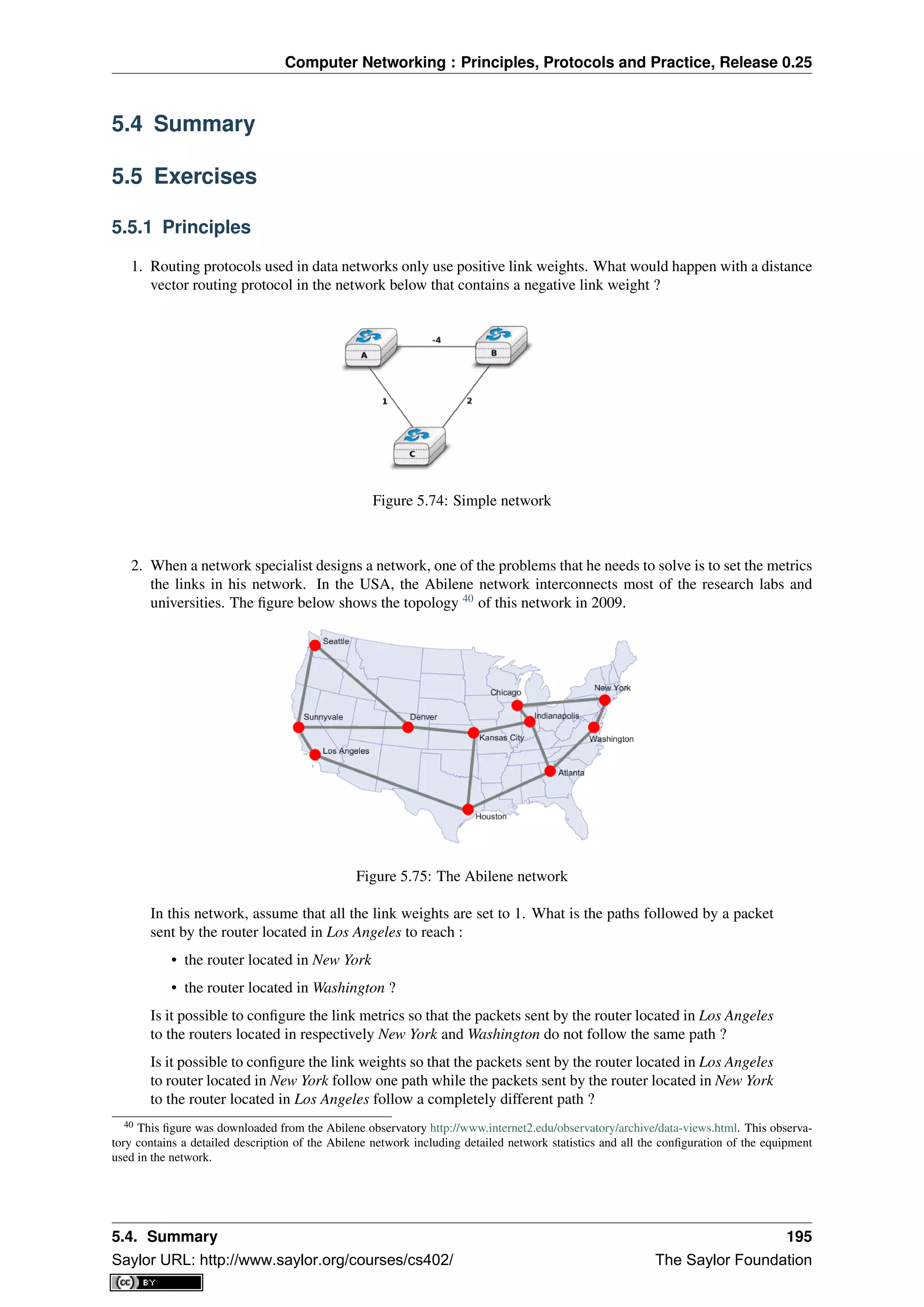
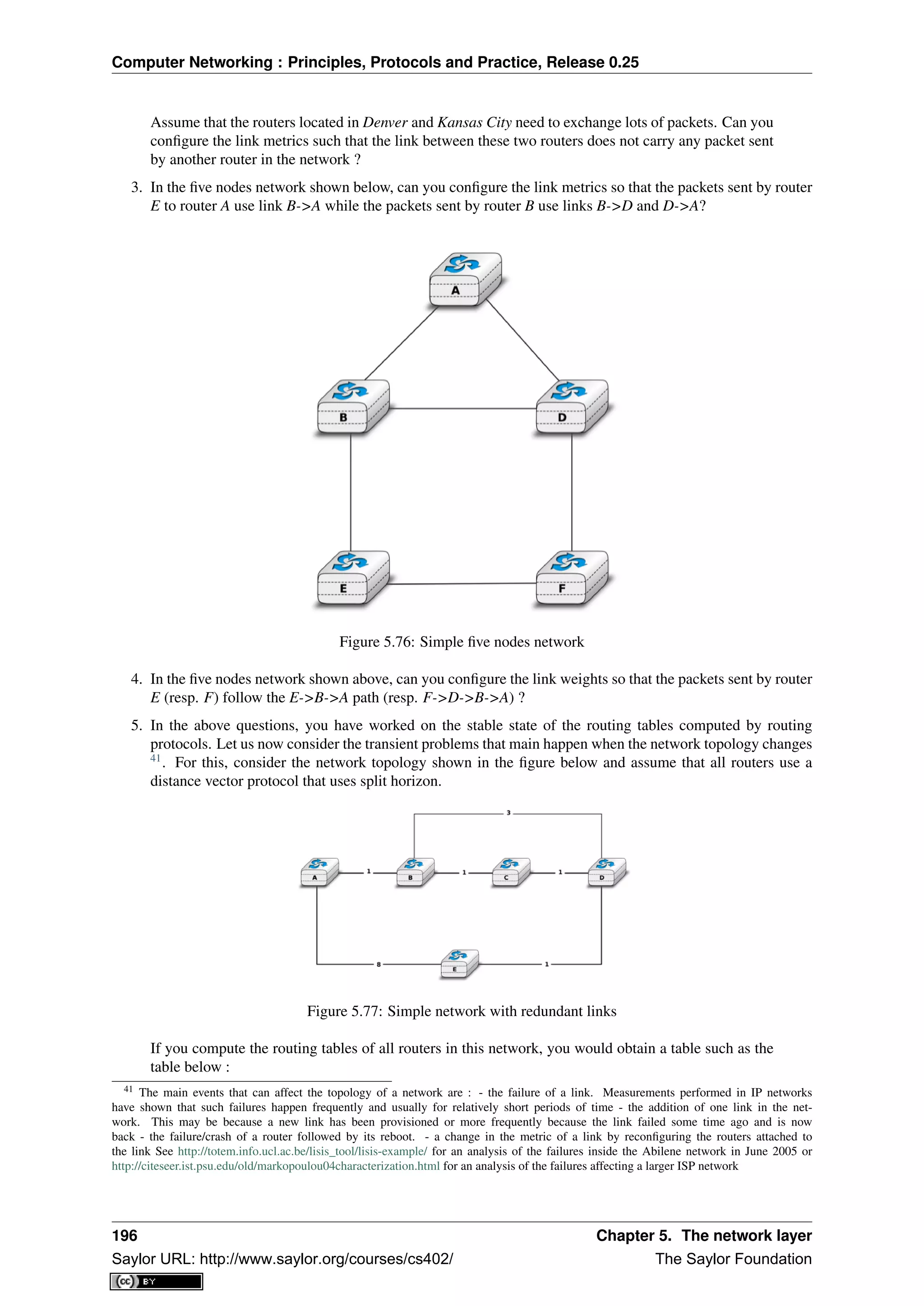
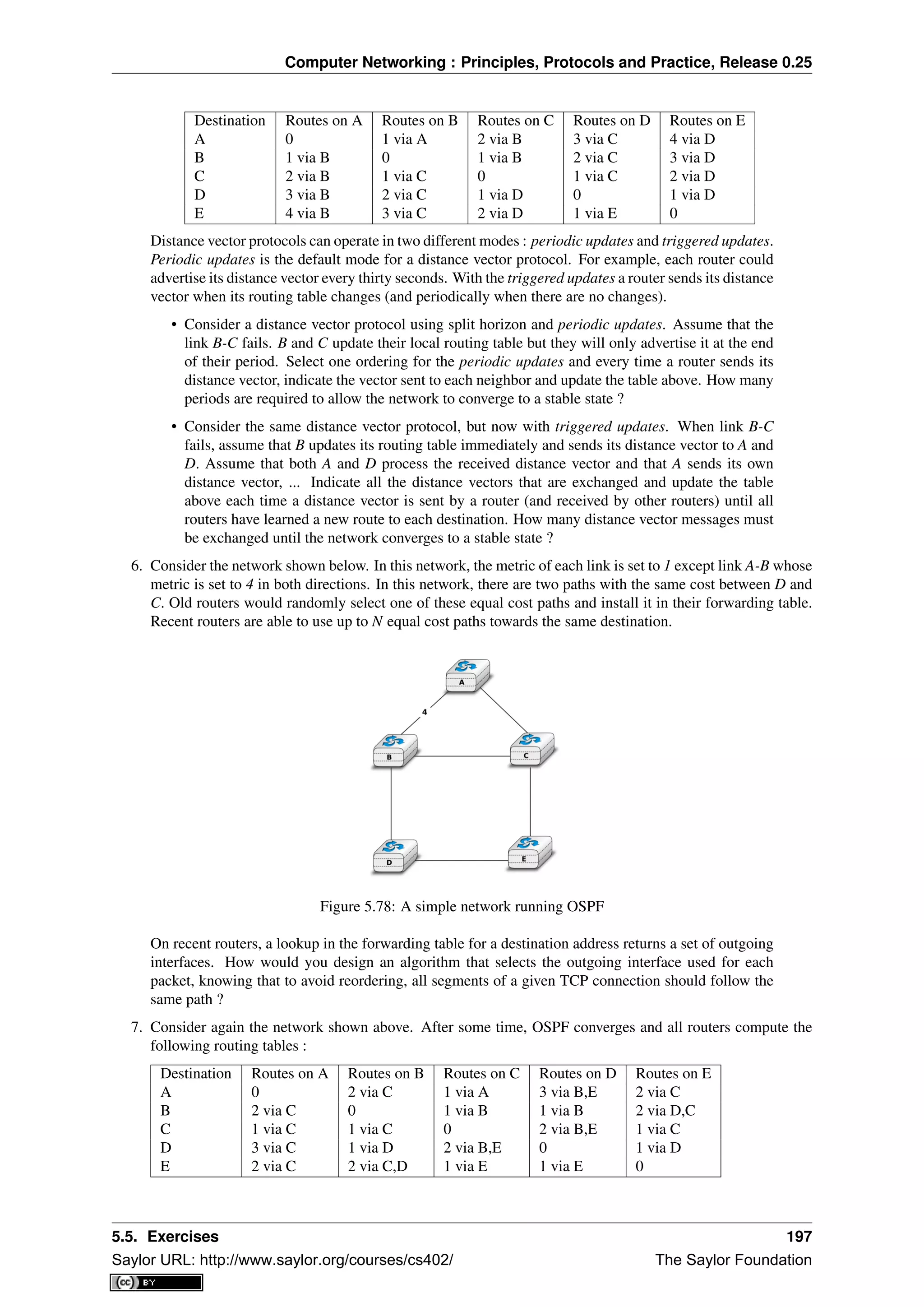
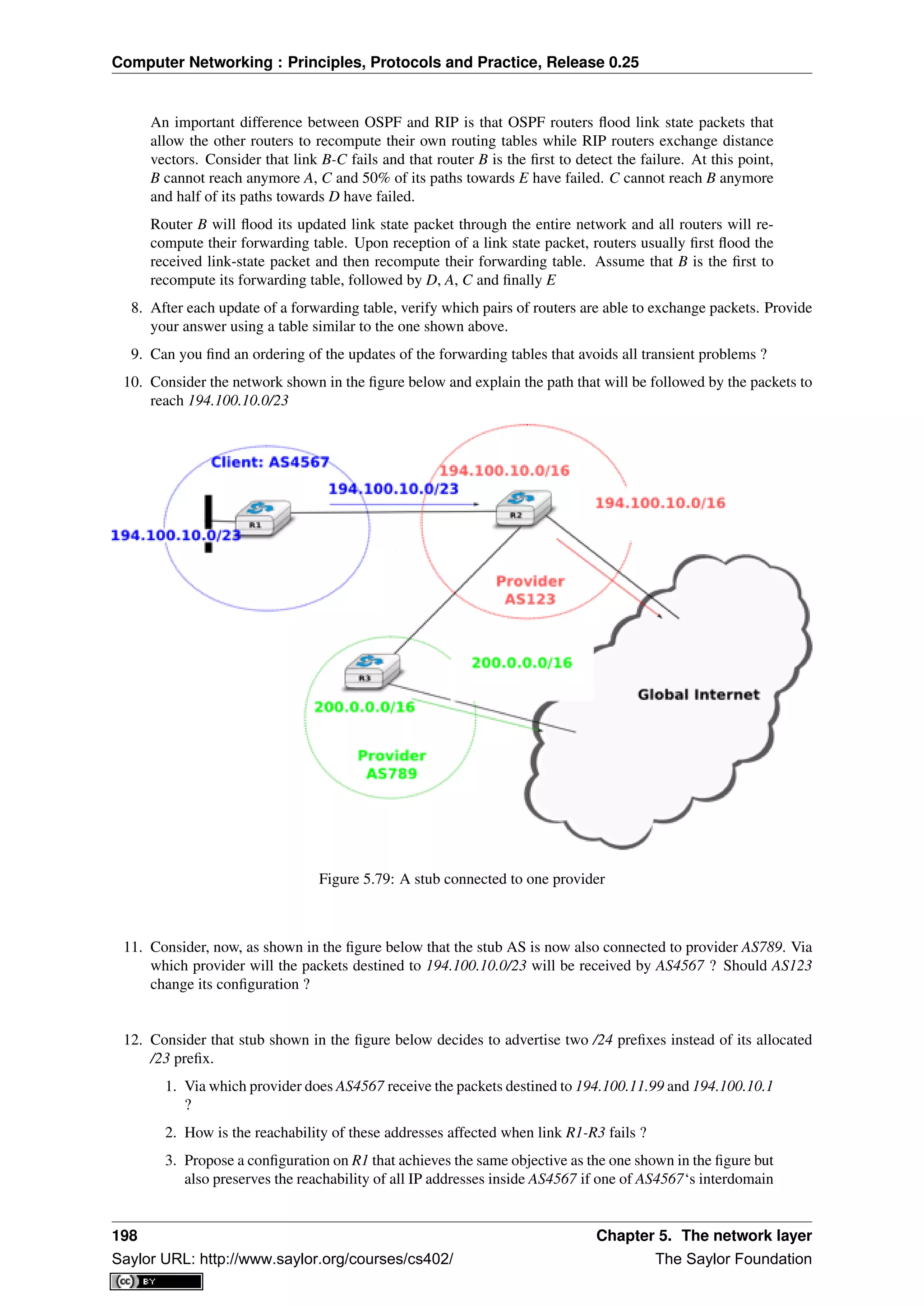
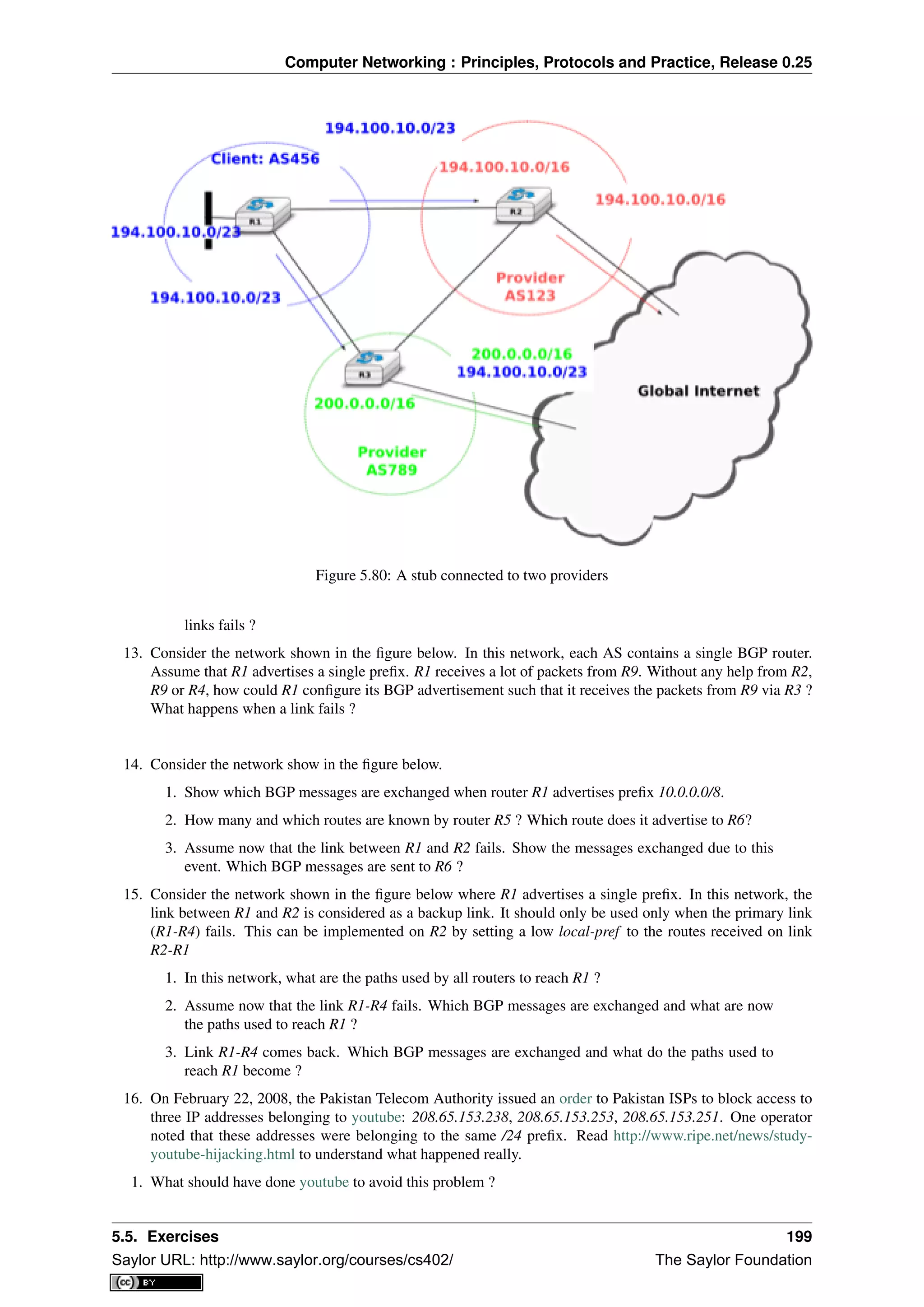
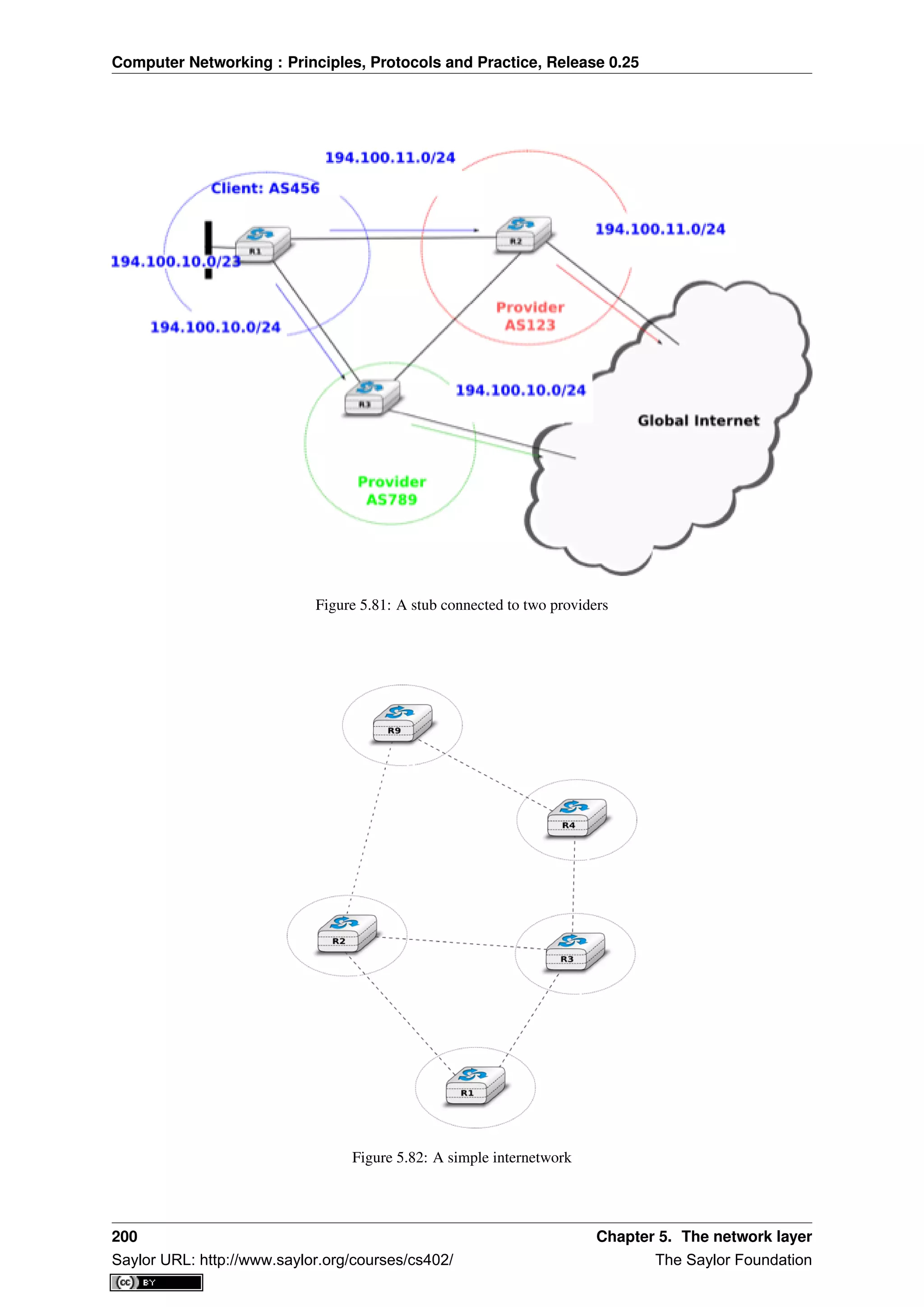
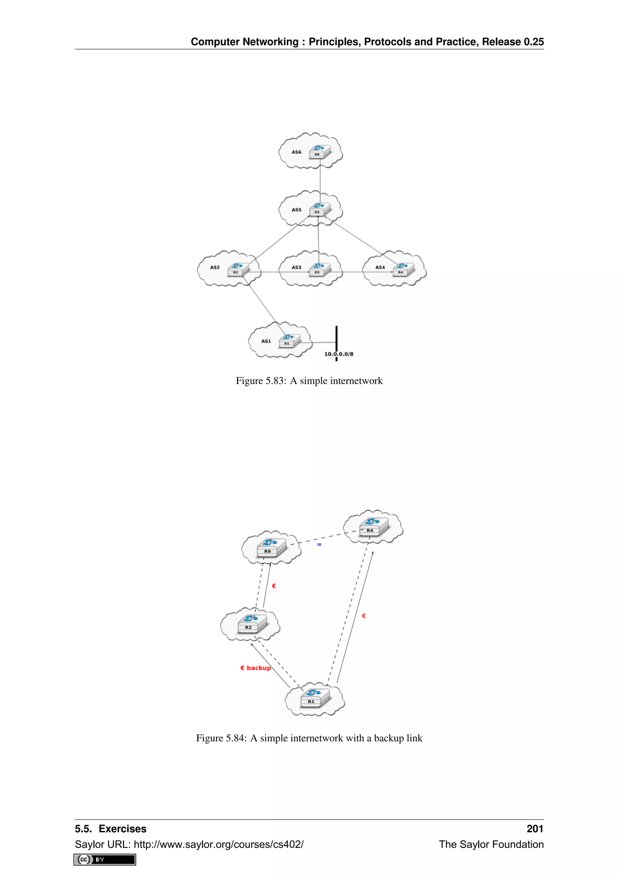
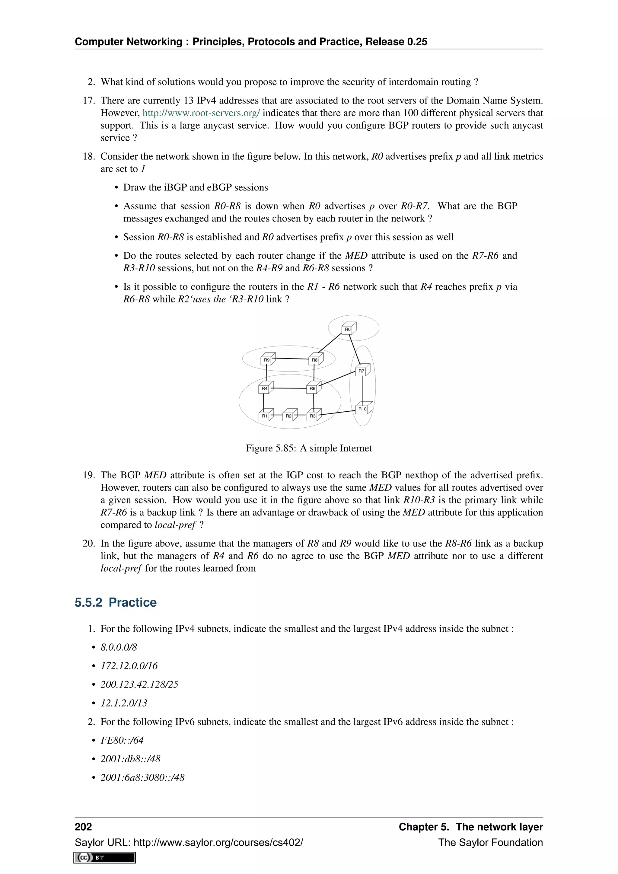
![Computer Networking : Principles, Protocols and Practice, Release 0.25
3. Researchers and network operators collect and expose lots of BGP data. For this, they establish eBGP
sessions between data collection routers and production routers located in operational networks. Several
data collection routers are available, the most popular ones are :
• http://www.routeviews.org
• http://www.ripe.net/ris
For this exercise, you will use one of the routeviews BGP routers. You can access one of these routers
by using telnet. Once logged on the router, you can use the router’s command line interface to analyse
its BGP routing table.
telnet route-views.routeviews.org
Trying 128.223.51.103...
Connected to route-views.routeviews.org.
Escape character is ’^]’.
C
**********************************************************************
Oregon Exchange BGP Route Viewer
route-views.oregon-ix.net / route-views.routeviews.org
route views data is archived on http://archive.routeviews.org
This hardware is part of a grant from Cisco Systems.
Please contact help@routeviews.org if you have questions or
comments about this service, its use, or if you might be able to
contribute your view.
This router has views of the full routing tables from several ASes.
The list of ASes is documented under "Current Participants" on
http://www.routeviews.org/.
**************
route-views.routeviews.org is now using AAA for logins. Login with
username "rviews". See http://routeviews.org/aaa.html
**********************************************************************
User Access Verification
Username: rviews
route-views.oregon-ix.net>
This router has eBGP sessions with routers from several ISPs. See
http://www.routeviews.org/peers/route-views.oregon-ix.net.txt for an up-to-date list of all eBGP
sessions maintained by this router.
Among all the commands supported by this router, the show ip bgp command is very useful. This
command takes an IPv4 prefix as parameter and allows you to retrieve all the routes that this routers
has received in its Adj-RIB-In for the specified prefix.
1. Use show ip bgp 130.104.0.0/16 to find the best path used by this router to reach UCLouvain
2. Knowing that 130.104.0.0/16 is announced by belnet (AS2611), what are, according to this BGP
routing tables, the ASes that peer with belnet
3. Do the same analysis for one of the IPv4 prefixes assigned to Skynet (AS5432) : 62.4.128.0/17.
The output of the show ip bgp 62.4.128.0/17 reveals something strange as it seems that one of
the paths towards this prefix passes twice via AS5432. Can you explain this ?
2905 702 1239 5432 5432
196.7.106.245 from 196.7.106.245 (196.7.106.245)
Origin IGP, metric 0, localpref 100, valid, external
4. netkit allows to easily perform experiments by using an emulated environment is is composed of virtual
5.5. Exercises 203
Saylor URL: http://www.saylor.org/courses/cs402/ The Saylor Foundation](https://image.slidesharecdn.com/computer-networking-principles-bonaventure-1-30-31-otc1-150825141809-lva1-app6891/75/Computer-networking-principles-bonaventure-1-30-31-otc1-207-2048.jpg)
![Computer Networking : Principles, Protocols and Practice, Release 0.25
machines running User Model Linux. netkit allows to setup a small network in a lab and configure it as if
you had access to several PCs interconnected by using cables and network equipments.
A netkit lab is defined as a few configuration files and scripts :
lab.conf is a textfile that defines the virtual machines and the network topology. A simple lab.conf
file is shown below.
LAB_DESCRIPTION="a string describing the lab"
LAB_VERSION=1.0
LAB_AUTHOR="the author of the lab"
LAB_EMAIL="email address of the author"
h1[0]="lan"
h2[0]="lan"
This configuration file requests the creation of two virtual machines, named h1 and h2. Each of these hosts has one net
A host.startup file for each host (h1.startup and h2.startup in the example above). This file is
a shell script that is executed at the end of the boot of the virtual host. This is typically in this
script that the network interfaces are configured and the daemons are launched. A directory for
each host (h1 and h2 in the example above). This directory is used to store configuration files
that must be copied on the virtual machine’s filesystems when they are first created.
netkit contains several scripts that can be used to run a lab. lstart allows to launch a lab and lhalt
allows to halt the machines at the end of a lab. If you need to exchange files between the virtual
machines and the Linux host on which netkit runs, note that the virtual hosts mount the directory that
contains the running lab in /hostlab and your home directory in /hosthome.
For this exercise, you will use a netkit lab containing 4 hosts and two routers. The configuration files
are available exercises/labs/lab-2routers.tar.gz. The network topology of this lab is
shown in the figure below.
Figure 5.86: The two routers lab
The lab.conf file for this lab is shown below.
h1[0]="lan1"
h2[0]="lan1"
h3[0]="lan2"
router1[0]="lan1"
router1[1]="lan2"
router2[0]="lan2"
router2[1]="lan3"
h4[0]="lan3"
In this network, we will use subnet 172.12.1.0/24 for lan1, 172.12.2.0/24 for lan2 and 172.12.3.0/24
for lan3.
On Linux, the IP addresses assigned on an interface can be configured by using ifconfig(8).
When ifconfig(8) is used without parameters, it lists all the existing interfaces of the host with
their configuration. A sample ifconfig(8) output is shown below.
host:~# ifconfig
eth0 Link encap:Ethernet HWaddr FE:3A:59:CD:59:AD
Inet addr:192.168.1.1 Bcast:192.168.1.255 Mask:255.255.255.0
204 Chapter 5. The network layer
Saylor URL: http://www.saylor.org/courses/cs402/ The Saylor Foundation](https://image.slidesharecdn.com/computer-networking-principles-bonaventure-1-30-31-otc1-150825141809-lva1-app6891/75/Computer-networking-principles-bonaventure-1-30-31-otc1-208-2048.jpg)
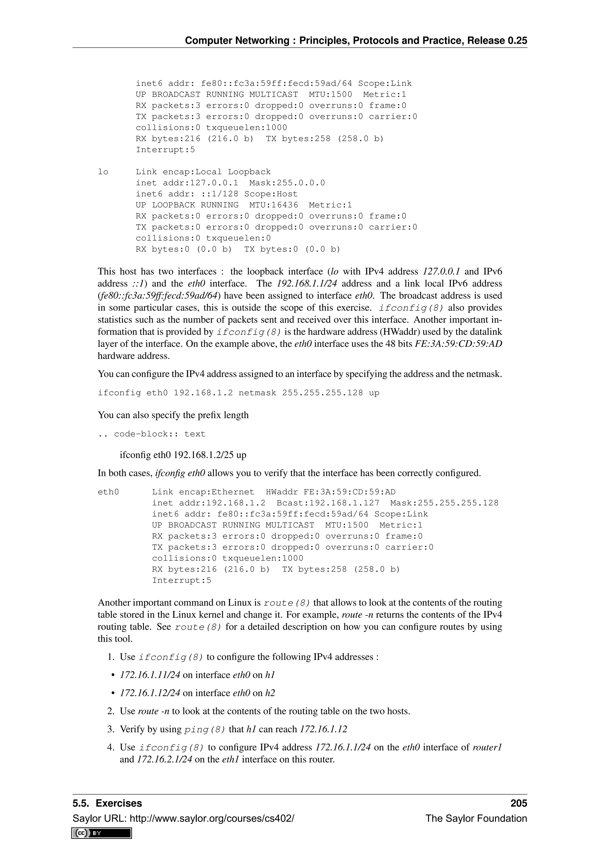
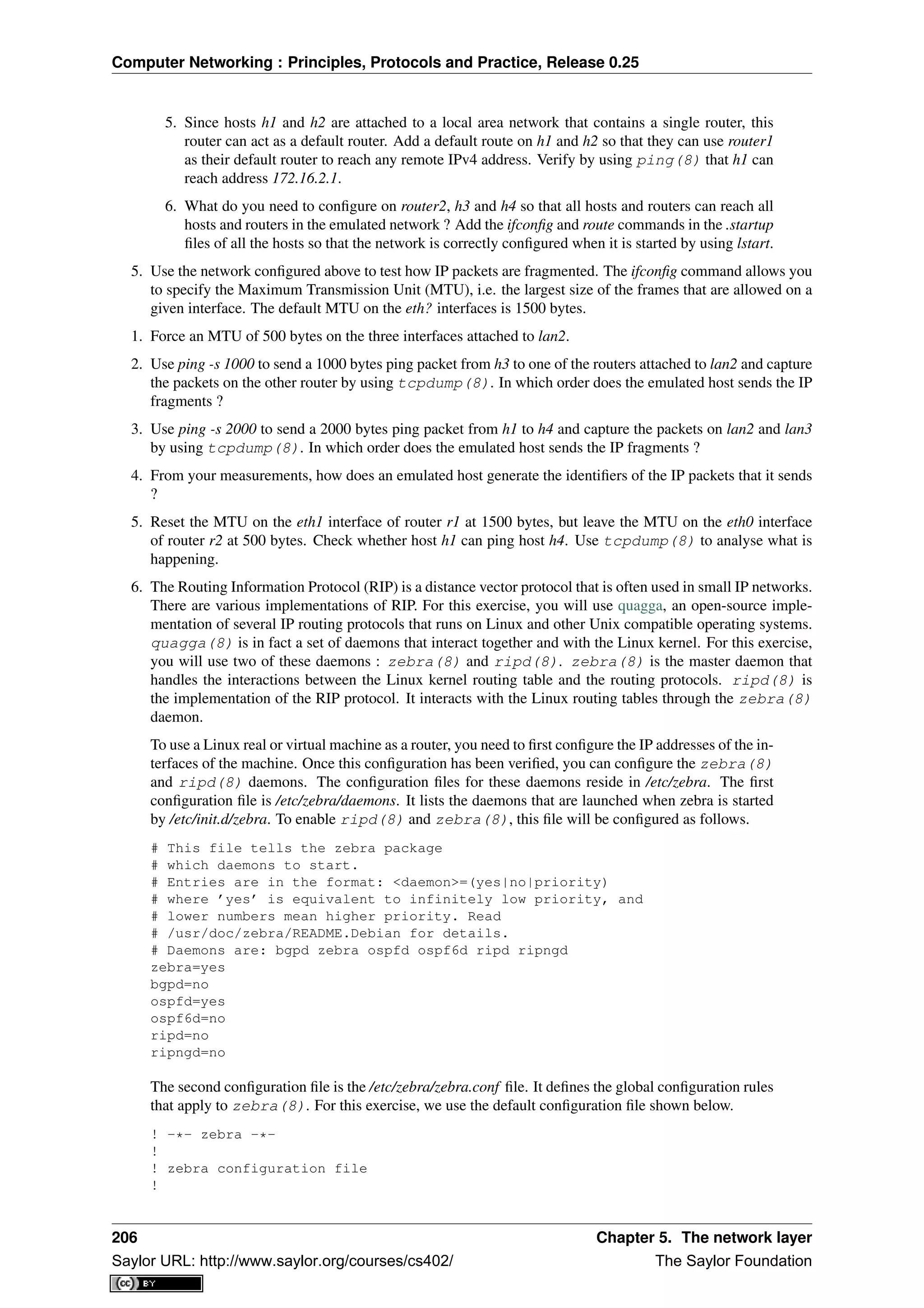
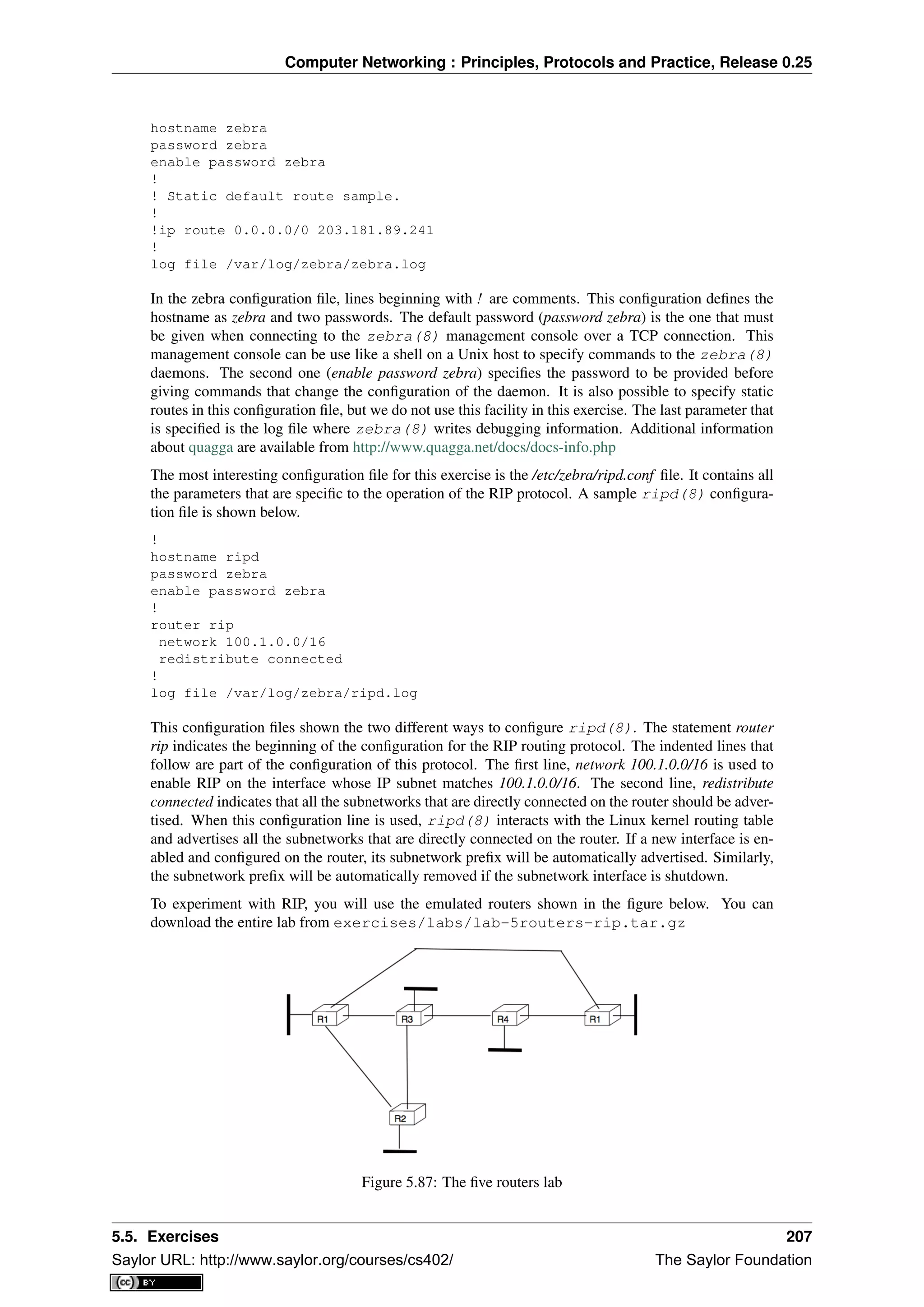
![Computer Networking : Principles, Protocols and Practice, Release 0.25
The lab.conf describing the topology and the interfaces used on all hosts is shown below/
r1[0]="A"
r1[1]="B"
r1[2]="F"
r1[3]="V"
r2[0]="A"
r2[1]="C"
r2[2]="W"
r3[0]="B"
r3[1]="C"
r3[2]="D"
r3[3]="X"
r4[0]="D"
r4[1]="E"
r4[2]="Y"
r5[0]="E"
r5[1]="F"
r5[2]="Z"
There are two types of subnetworks in this topology. The subnetworks from the 172.16.0.0/16 prefix
are used on the links between routers while the subnetworks from the 192.168.0.0/16 prefix are used
on the local area networks that are attached to a single router.
A router can be configured in two different ways : by specifying configuration files and by typing the
commands directly on the router by using telnet(1). The first four routers have been configured
in the provided configuration files. Look at r1.startup and the configurations files in r1/tmp/zebra in
the lab’s directory for router r1. The r?.startup files contain the ifconfig(8) commands that are
used to configure the interfaces of each virtual router. The configuration files located in r?/tmp/zebra
are also copied automatically on the virtual router when it boots.
1. Launch the lab by using lstart and verify that router r1 can reach 192.168.1.1, 192.168.2.2,
192.168.3.3 and 192.168.4.4. You can also traceroute(8) to determine what is the route
followed by your packets.
2. The ripd(8) daemon can also be configured by typing commands over a TCP connection.
ripd(8) listens on port 2602. On router r1, use telnet 127.0.0.1 2602 to connect to the
ripd(8) daemon. The default password is zebra. Once logged on the ripd(8) daemon,
you reach the > prompt where you can query the status of the router. By typing ? at the prompt,
you will find the list of supported commands. The show command is particularly useful, type
show ? to obtain the list of its sub options. For example, show ip rip will return the routing table
that is maintained by the ripd(8) daemon.
3. Disable interface eth3 on router r1 by typing ifconfig eth3 down on this router. Verify the
impact of this command on the routing tables of the other routers in the network. Re-enable
this interface by typing ifconfig eth3 up.
4. Do the same with the eth1 interface on router r3.
5. Edit the /etc/zebra/ripd.conf configuration file on router r5 so that this router becomes part of
the network. Verify that 192.168.5.5 is reachable by all routers inside the network.
7. The Open Shortest Path First (OSPF) protocol is a link-state protocol that is often used in en-
terprise IP networks. OSPF is implemented in the ospfd(8) daemon that is part of quagga.
We use the same topology as in the previous exercise. The netkit lab may be downloaded from
exercises/labs/lab-5routers-ospf.tar.gz.
The ospfd(8) daemon supports a more complex configuration that the ripd(8) daemon. A
sample configuration is shown below.
!
hostname ospfd
password zebra
enable password zebra
!
208 Chapter 5. The network layer
Saylor URL: http://www.saylor.org/courses/cs402/ The Saylor Foundation](https://image.slidesharecdn.com/computer-networking-principles-bonaventure-1-30-31-otc1-150825141809-lva1-app6891/75/Computer-networking-principles-bonaventure-1-30-31-otc1-212-2048.jpg)
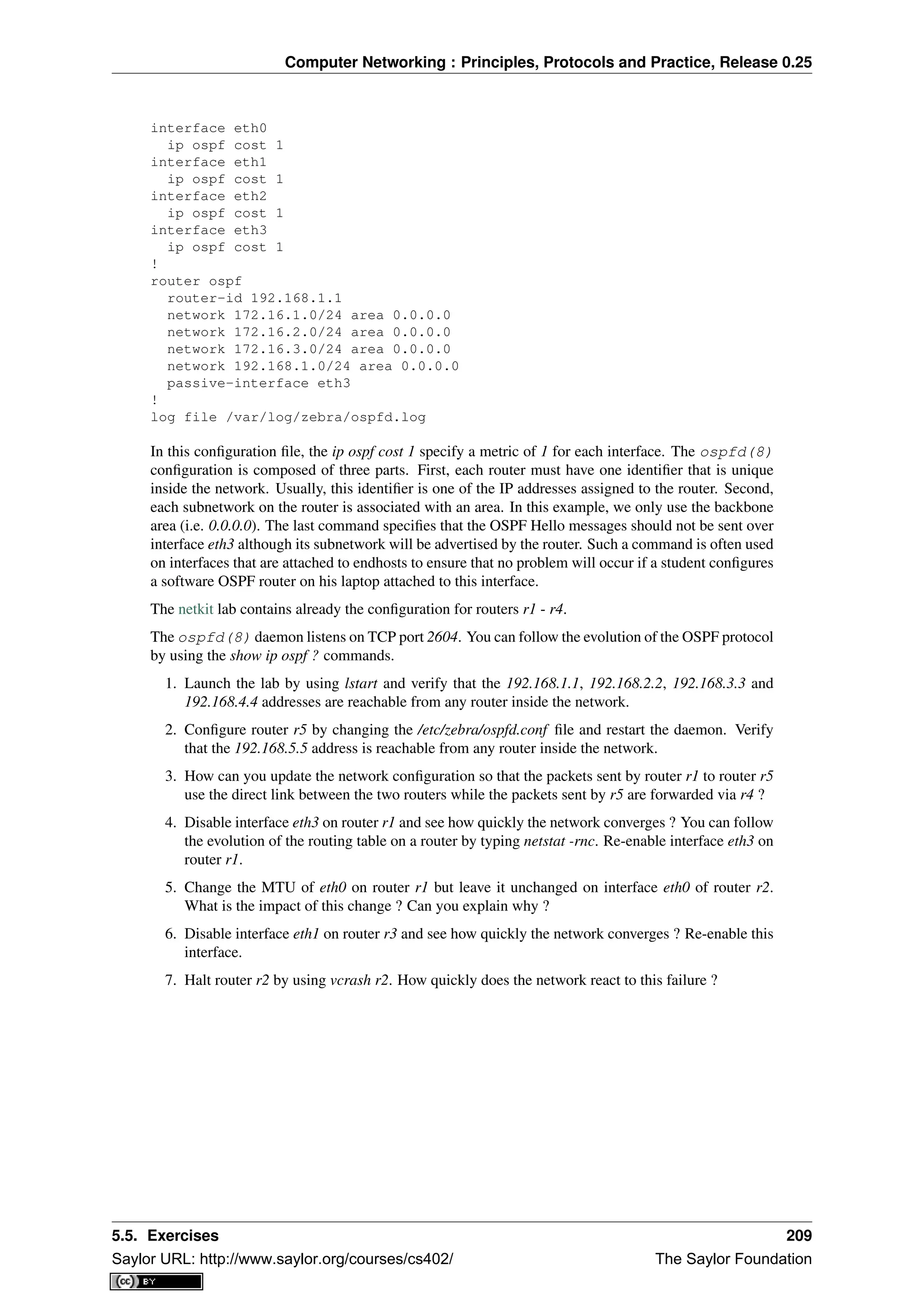
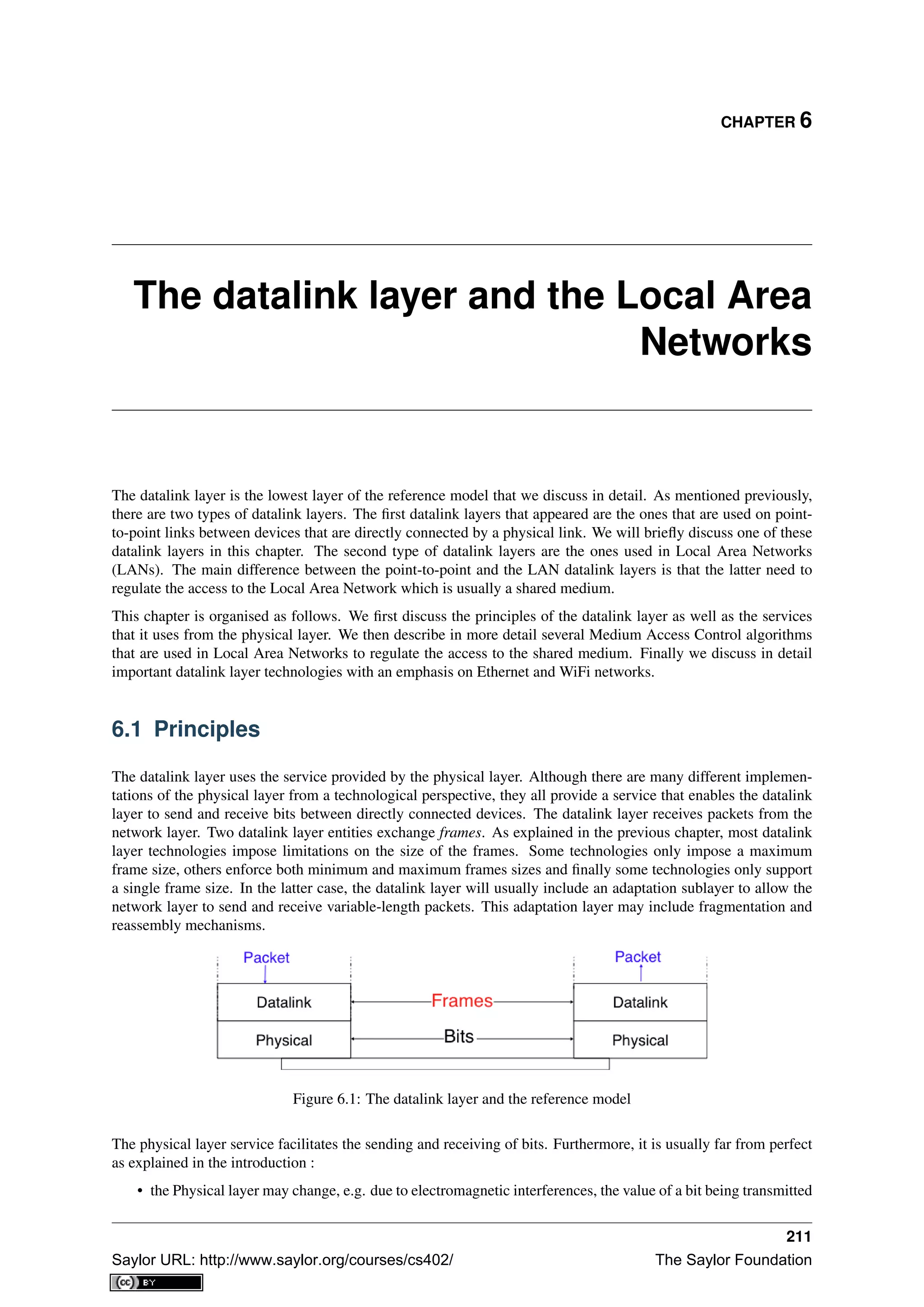
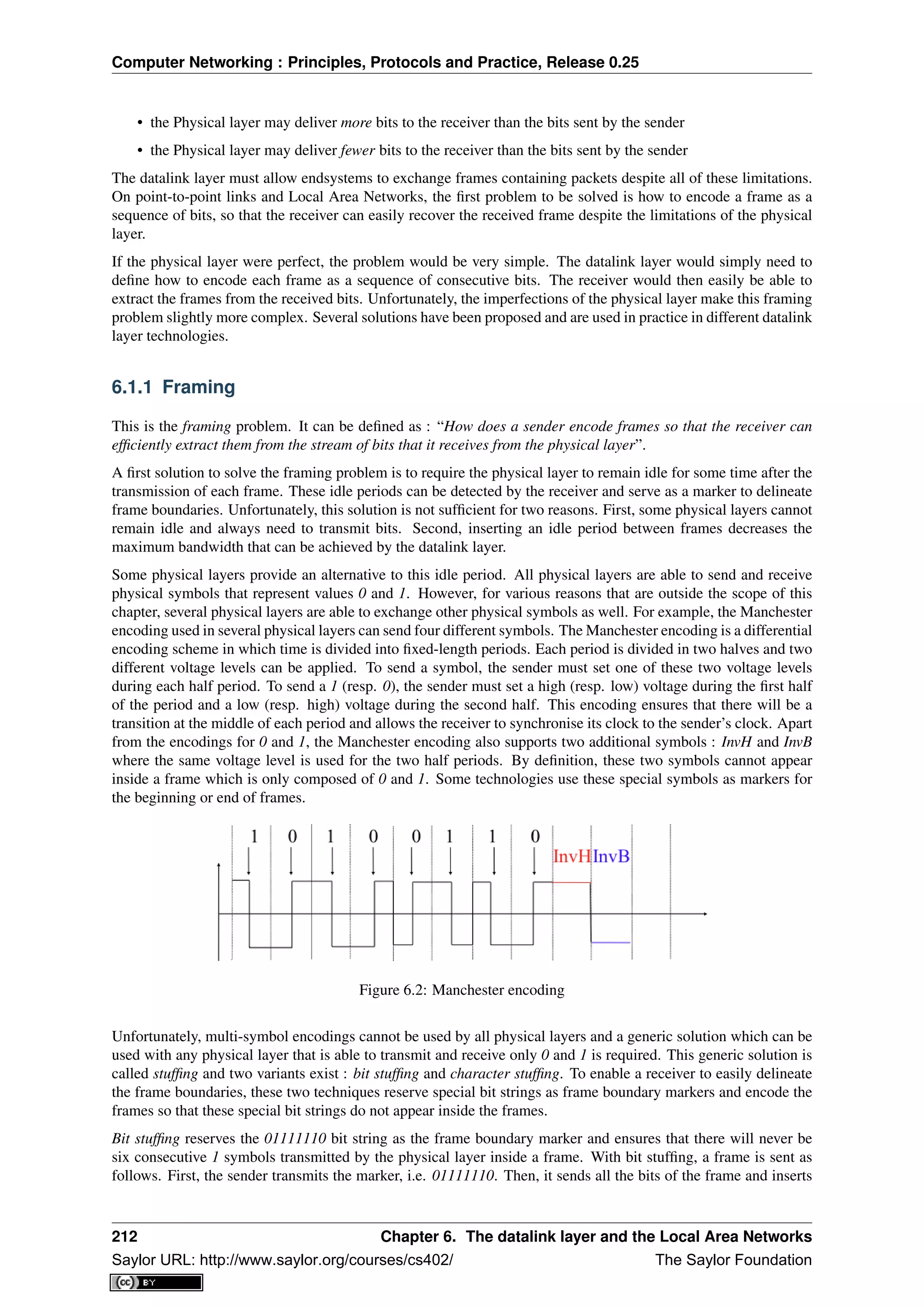
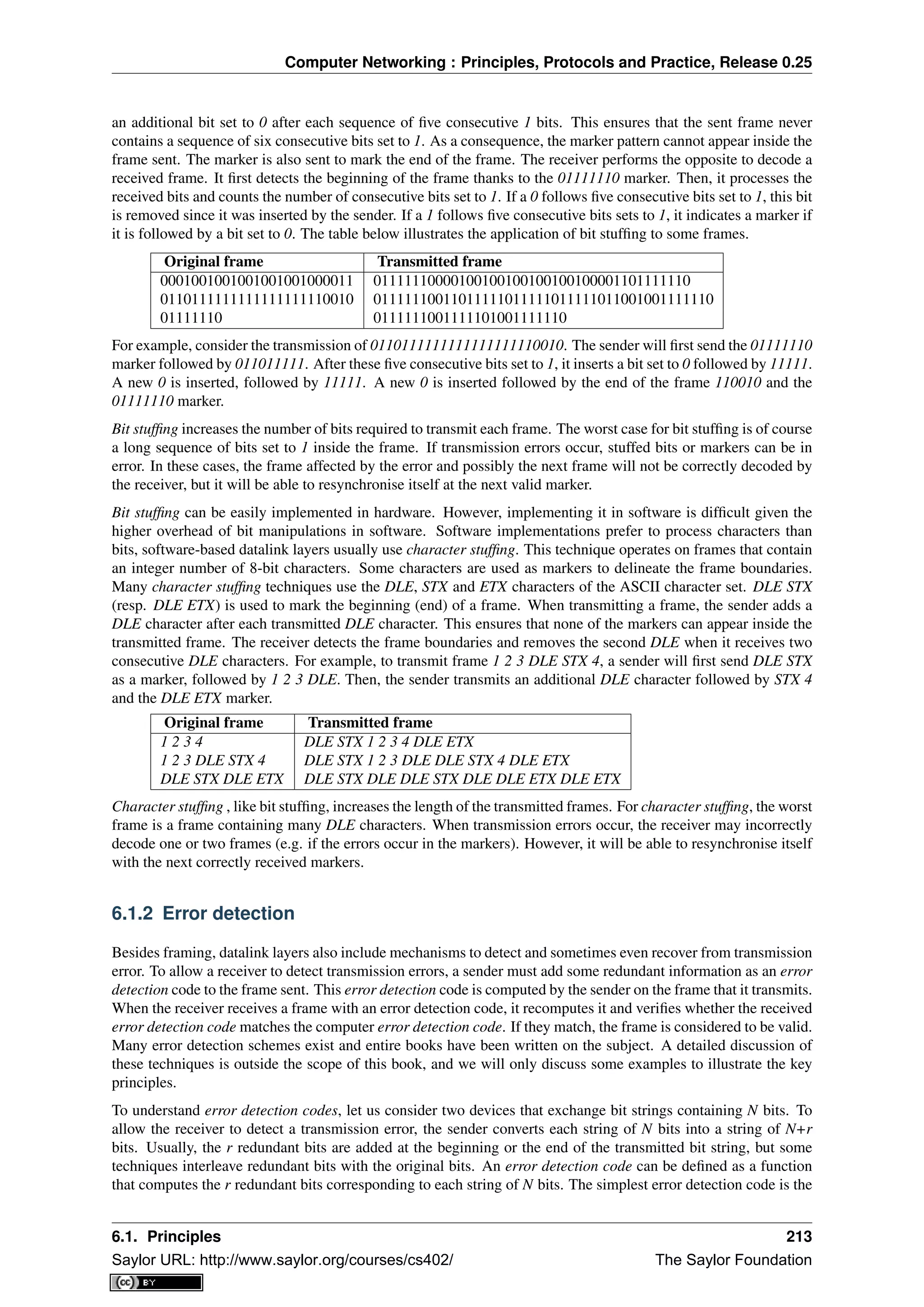
![Computer Networking : Principles, Protocols and Practice, Release 0.25
parity bit. There are two types of parity schemes : even and odd parity. With the even (resp. odd) parity scheme,
the redundant bit is chosen so that an even (resp. odd) number of bits are set to 1 in the transmitted bit string of
N+r bits. The receiver can easily recompute the parity of each received bit string and discard the strings with an
invalid parity. The parity scheme is often used when 7-bit characters are exchanged. In this case, the eighth bit is
often a parity bit. The table below shows the parity bits that are computed for bit strings containing three bits.
3 bits string Odd parity Even parity
000 1 0
001 0 1
010 0 1
100 0 1
111 0 1
110 1 0
101 1 0
011 1 0
The parity bit allows a receiver to detect transmission errors that have affected a single bit among the transmitted
N+r bits. If there are two or more bits in error, the receiver may not necessarily be able to detect the transmission
error. More powerful error detection schemes have been defined. The Cyclical Redundancy Checks (CRC) are
widely used in datalink layer protocols. An N-bits CRC can detect all transmission errors affecting a burst of
less than N bits in the transmitted frame and all transmission errors that affect an odd number of bits. Additional
details about CRCs may be found in [Williams1993].
It is also possible to design a code that allows the receiver to correct transmission errors. The simplest error
correction code is the triple modular redundancy (TMR). To transmit a bit set to 1 (resp. 0), the sender transmits
111 (resp. 000). When there are no transmission errors, the receiver can decode 111 as 1. If transmission errors
have affected a single bit, the receiver performs majority voting as shown in the table below. This scheme allows
the receiver to correct all transmission errors that affect a single bit.
Received bits Decoded bit
000 0
001 0
010 0
100 0
111 1
110 1
101 1
011 1
Other more powerful error correction codes have been proposed and are used in some applications. The Hamming
Code is a clever combination of parity bits that provides error detection and correction capabilities.
In practice, datalink layer protocols combine bit stuffing or character stuffing with a length indication in the frame
header and a checksum or CRC. The checksum/CRC is computed by the sender and placed in the frame before
applying bit/character stuffing.
6.2 Medium Access Control
Point-to-point datalink layers need to select one of the framing techniques described above and optionally add
retransmission algorithms such as those explained for the transport layer to provide a reliable service. Datalink
layers for Local Area Networks face two additional problems. A LAN is composed of several hosts that are
attached to the same shared physical medium. From a physical layer perspective, a LAN can be organised in four
different ways :
• a bus-shaped network where all hosts are attached to the same physical cable
• a ring-shaped where all hosts are attached to an upstream and a downstream node so that the entire network
forms a ring
• a star-shaped network where all hosts are attached to the same device
214 Chapter 6. The datalink layer and the Local Area Networks
Saylor URL: http://www.saylor.org/courses/cs402/ The Saylor Foundation](https://image.slidesharecdn.com/computer-networking-principles-bonaventure-1-30-31-otc1-150825141809-lva1-app6891/75/Computer-networking-principles-bonaventure-1-30-31-otc1-218-2048.jpg)
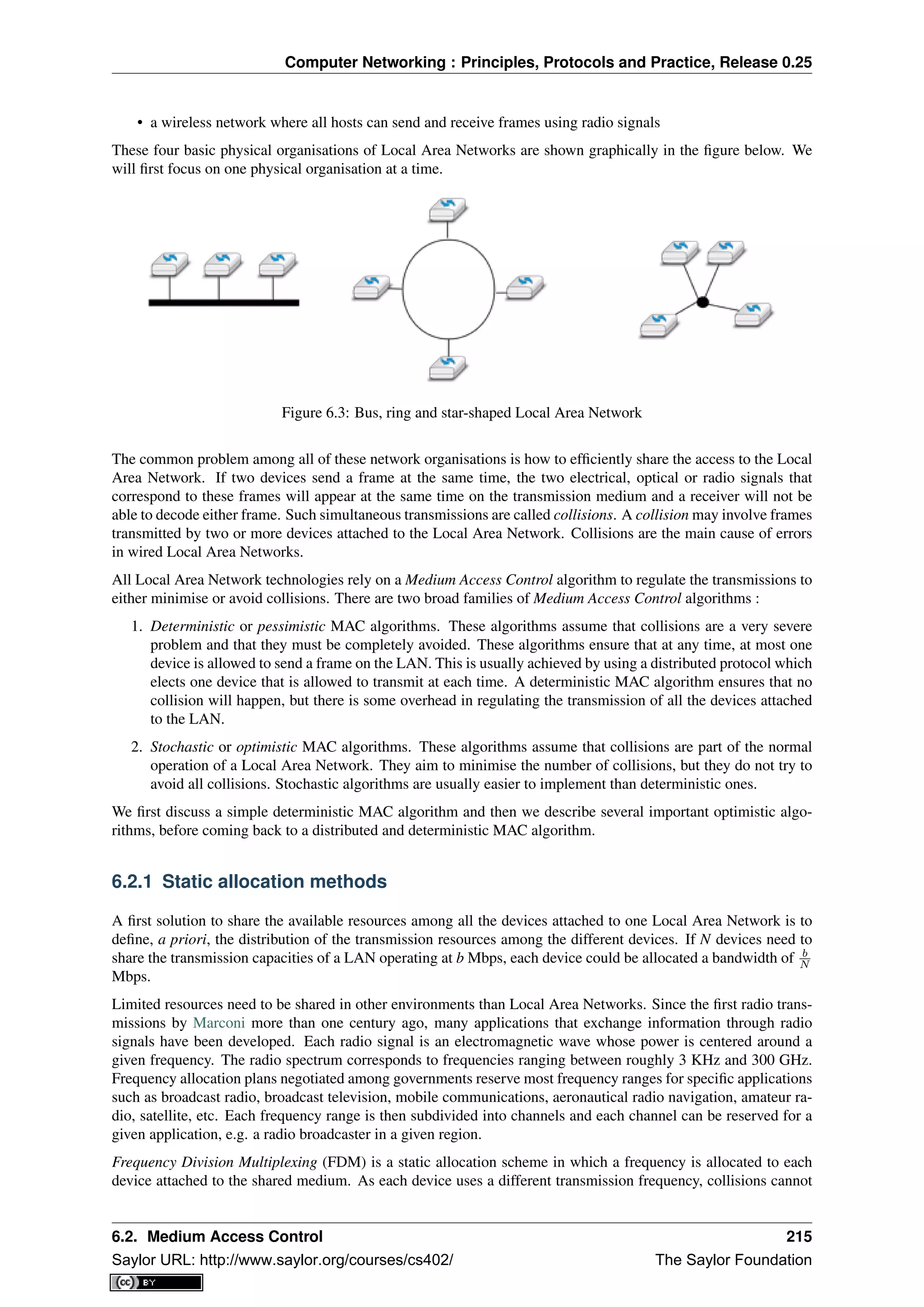
![Computer Networking : Principles, Protocols and Practice, Release 0.25
occur. In optical networks, a variant of FDM called Wavelength Division Multiplexing (WDM) can be used. An
optical fiber can transport light at different wavelengths without interference. With WDM, a different wavelength
is allocated to each of the devices that share the same optical fiber.
Time Division Multiplexing (TDM) is a static bandwidth allocation method that was initially defined for the tele-
phone network. In the fixed telephone network, a voice conversation is usually transmitted as a 64 Kbps signal.
Thus, a telephone conservation generates 8 KBytes per second or one byte every 125 microsecond. Telephone
conversations often need to be multiplexed together on a single line. For example, in Europe, thirty 64 Kbps voice
signals are multiplexed over a single 2 Mbps (E1) line. This is done by using Time Division Multiplexing (TDM).
TDM divides the transmission opportunities into slots. In the telephone network, a slot corresponds to 125 mi-
croseconds. A position inside each slot is reserved for each voice signal. The figure below illustrates TDM on a
link that is used to carry four voice conversations. The vertical lines represent the slot boundaries and the letters
the different voice conversations. One byte from each voice conversation is sent during each 125 microsecond
slot. The byte corresponding to a given conversation is always sent at the same position in each slot.
Figure 6.4: Time-division multiplexing
TDM as shown above can be completely static, i.e. the same conversations always share the link, or dynamic. In
the latter case, the two endpoints of the link must exchange messages specifying which conversation uses which
byte inside each slot. Thanks to these signalling messages, it is possible to dynamically add and remove voice
conversations from a given link.
TDM and FDM are widely used in telephone networks to support fixed bandwidth conversations. Using them
in Local Area Networks that support computers would probably be inefficient. Computers usually do not send
information at a fixed rate. Instead, they often have an on-off behaviour. During the on period, the computer tries
to send at the highest possible rate, e.g. to transfer a file. During the off period, which is often much longer than
the on period, the computer does not transmit any packet. Using a static allocation scheme for computers attached
to a LAN would lead to huge inefficiencies, as they would only be able to transmit at 1
N of the total bandwidth
during their on period, despite the fact that the other computers are in their off period and thus do not need to
transmit any information. The dynamic MAC algorithms discussed in the remainder of this chapter aim solve this
problem.
6.2.2 ALOHA
In the 1960s, computers were mainly mainframes with a few dozen terminals attached to them. These terminals
were usually in the same building as the mainframe and were directly connected to it. In some cases, the terminals
were installed in remote locations and connected through a modem attached to a dial-up line. The university
of Hawaii chose a different organisation. Instead of using telephone lines to connect the distant terminals, they
developed the first packet radio technology [Abramson1970]. Until then, computer networks were built on top of
either the telephone network or physical cables. ALOHANet showed that it was possible to use radio signals to
interconnect computers.
The first version of ALOHANet, described in [Abramson1970], operated as follows: First, the terminals and the
mainframe exchanged fixed-length frames composed of 704 bits. Each frame contained 80 8-bit characters, some
control bits and parity information to detect transmission errors. Two channels in the 400 MHz range were reserved
for the operation of ALOHANet. The first channel was used by the mainframe to send frames to all terminals.
The second channel was shared among all terminals to send frames to the mainframe. As all terminals share the
same transmission channel, there is a risk of collision. To deal with this problem as well as transmission errors,
the mainframe verified the parity bits of the received frame and sent an acknowledgement on its channel for each
correctly received frame. The terminals on the other hand had to retransmit the unacknowledged frames. As for
TCP, retransmitting these frames immediately upon expiration of a fixed timeout is not a good approach as several
terminals may retransmit their frames at the same time leading to a network collapse. A better approach, but still
far from perfect, is for each terminal to wait a random amount of time after the expiration of its retransmission
timeout. This avoids synchronisation among multiple retransmitting terminals.
216 Chapter 6. The datalink layer and the Local Area Networks
Saylor URL: http://www.saylor.org/courses/cs402/ The Saylor Foundation](https://image.slidesharecdn.com/computer-networking-principles-bonaventure-1-30-31-otc1-150825141809-lva1-app6891/75/Computer-networking-principles-bonaventure-1-30-31-otc1-220-2048.jpg)
![Computer Networking : Principles, Protocols and Practice, Release 0.25
The pseudo-code below shows the operation of an ALOHANet terminal. We use this python syntax for all Medium
Access Control algorithms described in this chapter. The algorithm is applied to each new frame that needs to be
transmitted. It attempts to transmit a frame at most max times (while loop). Each transmission attempt is performed
as follows: First, the frame is sent. Each frame is protected by a timeout. Then, the terminal waits for either a
valid acknowledgement frame or the expiration of its timeout. If the terminal receives an acknowledgement, the
frame has been delivered correctly and the algorithm terminates. Otherwise, the terminal waits for a random time
and attempts to retransmit the frame.
# ALOHA
N=1
while N<= max :
send(frame)
wait(ack_on_return_channel or timeout)
if (ack_on_return_channel):
break # transmission was successful
else:
# timeout
wait(random_time)
N=N+1
else:
# Too many transmission attempts
[Abramson1970] analysed the performance of ALOHANet under particular assumptions and found that ALO-
HANet worked well when the channel was lightly loaded. In this case, the frames are rarely retransmitted and the
channel traffic, i.e. the total number of (correct and retransmitted) frames transmitted per unit of time is close to
the channel utilization, i.e. the number of correctly transmitted frames per unit of time. Unfortunately, the analysis
also reveals that the channel utilization reaches its maximum at 1
2×e = 0.186 times the channel bandwidth. At
higher utilization, ALOHANet becomes unstable and the network collapses due to collided retransmissions.
Note: Amateur packet radio
Packet radio technologies have evolved in various directions since the first experiments performed at the University
of Hawaii. The Amateur packet radio service developed by amateur radio operators is one of the descendants
ALOHANet. Many amateur radio operators are very interested in new technologies and they often spend countless
hours developing new antennas or transceivers. When the first personal computers appeared, several amateur radio
operators designed radio modems and their own datalink layer protocols [KPD1985] [BNT1997]. This network
grew and it was possible to connect to servers in several European countries by only using packet radio relays.
Some amateur radio operators also developed TCP/IP protocol stacks that were used over the packet radio service.
Some parts of the amateur packet radio network are connected to the global Internet and use the 44.0.0.0/8 prefix.
Many improvements to ALOHANet have been proposed since the publication of [Abramson1970], and this tech-
nique, or some of its variants, are still found in wireless networks today. The slotted technique proposed in
[Roberts1975] is important because it shows that a simple modification can significantly improve channel utiliza-
tion. Instead of allowing all terminals to transmit at any time, [Roberts1975] proposed to divide time into slots
and allow terminals to transmit only at the beginning of each slot. Each slot corresponds to the time required to
transmit one fixed size frame. In practice, these slots can be imposed by a single clock that is received by all
terminals. In ALOHANet, it could have been located on the central mainframe. The analysis in [Roberts1975]
reveals that this simple modification improves the channel utilization by a factor of two.
6.2.3 Carrier Sense Multiple Access
ALOHA and slotted ALOHA can easily be implemented, but unfortunately, they can only be used in networks that
are very lightly loaded. Designing a network for a very low utilisation is possible, but it clearly increases the cost
of the network. To overcome the problems of ALOHA, many Medium Access Control mechanisms have been
proposed which improve channel utilization. Carrier Sense Multiple Access (CSMA) is a significant improvement
compared to ALOHA. CSMA requires all nodes to listen to the transmission channel to verify that it is free before
transmitting a frame [KT1975]. When a node senses the channel to be busy, it defers its transmission until the
channel becomes free again. The pseudo-code below provides a more detailed description of the operation of
CSMA.
6.2. Medium Access Control 217
Saylor URL: http://www.saylor.org/courses/cs402/ The Saylor Foundation](https://image.slidesharecdn.com/computer-networking-principles-bonaventure-1-30-31-otc1-150825141809-lva1-app6891/75/Computer-networking-principles-bonaventure-1-30-31-otc1-221-2048.jpg)
![Computer Networking : Principles, Protocols and Practice, Release 0.25
# persistent CSMA
N=1
while N<= max :
wait(channel_becomes_free)
send(frame)
wait(ack or timeout)
if ack :
break # transmission was successful
else :
# timeout
N=N+1
# end of while loop
# Too many transmission attempts
The above pseudo-code is often called persistent CSMA [KT1975] as the terminal will continuously listen to the
channel and transmit its frame as soon as the channel becomes free. Another important variant of CSMA is the
non-persistent CSMA [KT1975]. The main difference between persistent and non-persistent CSMA described
in the pseudo-code below is that a non-persistent CSMA node does not continuously listen to the channel to
determine when it becomes free. When a non-persistent CSMA terminal senses the transmission channel to be
busy, it waits for a random time before sensing the channel again. This improves channel utilization compared to
persistent CSMA. With persistent CSMA, when two terminals sense the channel to be busy, they will both transmit
(and thus cause a collision) as soon as the channel becomes free. With non-persistent CSMA, this synchronisation
does not occur, as the terminals wait a random time after having sensed the transmission channel. However, the
higher channel utilization achieved by non-persistent CSMA comes at the expense of a slightly higher waiting
time in the terminals when the network is lightly loaded.
# Non persistent CSMA
N=1
while N<= max :
listen(channel)
if free(channel):
send(frame)
wait(ack or timeout)
if received(ack) :
break # transmission was successful
else :
# timeout
N=N+1
else:
wait(random_time)
# end of while loop
# Too many transmission attempts
[KT1975] analyzes in detail the performance of several CSMA variants. Under some assumptions about the trans-
mission channel and the traffic, the analysis compares ALOHA, slotted ALOHA, persistent and non-persistent
CSMA. Under these assumptions, ALOHA achieves a channel utilization of only 18.4% of the channel capacity.
Slotted ALOHA is able to use 36.6% of this capacity. Persistent CSMA improves the utilization by reaching
52.9% of the capacity while non-persistent CSMA achieves 81.5% of the channel capacity.
6.2.4 Carrier Sense Multiple Access with Collision Detection
CSMA improves channel utilization compared to ALOHA. However, the performance can still be improved,
especially in wired networks. Consider the situation of two terminals that are connected to the same cable. This
cable could, for example, be a coaxial cable as in the early days of Ethernet [Metcalfe1976]. It could also be built
with twisted pairs. Before extending CSMA, it is useful to understand more intuitively, how frames are transmitted
in such a network and how collisions can occur. The figure below illustrates the physical transmission of a frame
on such a cable. To transmit its frame, host A must send an electrical signal on the shared medium. The first step
is thus to begin the transmission of the electrical signal. This is point (1) in the figure below. This electrical signal
will travel along the cable. Although electrical signals travel fast, we know that information cannot travel faster
than the speed of light (i.e. 300.000 kilometers/second). On a coaxial cable, an electrical signal is slightly slower
218 Chapter 6. The datalink layer and the Local Area Networks
Saylor URL: http://www.saylor.org/courses/cs402/ The Saylor Foundation](https://image.slidesharecdn.com/computer-networking-principles-bonaventure-1-30-31-otc1-150825141809-lva1-app6891/75/Computer-networking-principles-bonaventure-1-30-31-otc1-222-2048.jpg)
![Computer Networking : Principles, Protocols and Practice, Release 0.25
than the speed of light and 200.000 kilometers per second is a reasonable estimation. This implies that if the cable
has a length of one kilometer, the electrical signal will need 5 microseconds to travel from one end of the cable to
the other. The ends of coaxial cables are equipped with termination points that ensure that the electrical signal is
not reflected back to its source. This is illustrated at point (3) in the figure, where the electrical signal has reached
the left endpoint and host B. At this point, B starts to receive the frame being transmitted by A. Notice that there is
a delay between the transmission of a bit on host A and its reception by host B. If there were other hosts attached
to the cable, they would receive the first bit of the frame at slightly different times. As we will see later, this timing
difference is a key problem for MAC algorithms. At point (4), the electrical signal has reached both ends of the
cable and occupies it completely. Host A continues to transmit the electrical signal until the end of the frame. As
shown at point (5), when the sending host stops its transmission, the electrical signal corresponding to the end of
the frame leaves the coaxial cable. The channel becomes empty again once the entire electrical signal has been
removed from the cable.
Figure 6.5: Frame transmission on a shared bus
Now that we have looked at how a frame is actually transmitted as an electrical signal on a shared bus, it is
interesting to look in more detail at what happens when two hosts transmit a frame at almost the same time. This
is illustrated in the figure below, where hosts A and B start their transmission at the same time (point (1)). At this
time, if host C senses the channel, it will consider it to be free. This will not last a long time and at point (2) the
electrical signals from both host A and host B reach host C. The combined electrical signal (shown graphically as
the superposition of the two curves in the figure) cannot be decoded by host C. Host C detects a collision, as it
receives a signal that it cannot decode. Since host C cannot decode the frames, it cannot determine which hosts
are sending the colliding frames. Note that host A (and host B) will detect the collision after host C (point (3) in
the figure below).
As shown above, hosts detect collisions when they receive an electrical signal that they cannot decode. In a wired
network, a host is able to detect such a collision both while it is listening (e.g. like host C in the figure above)
and also while it is sending its own frame. When a host transmits a frame, it can compare the electrical signal
that it transmits with the electrical signal that it senses on the wire. At points (1) and (2) in the figure above,
host A senses only its own signal. At point (3), it senses an electrical signal that differs from its own signal and
can thus detects the collision. At this point, its frame is corrupted and it can stop its transmission. The ability
to detect collisions while transmitting is the starting point for the Carrier Sense Multiple Access with Collision
Detection (CSMA/CD) Medium Access Control algorithm, which is used in Ethernet networks [Metcalfe1976]
[802.3] . When an Ethernet host detects a collision while it is transmitting, it immediately stops its transmission.
Compared with pure CSMA, CSMA/CD is an important improvement since when collisions occur, they only last
until colliding hosts have detected it and stopped their transmission. In practice, when a host detects a collision, it
sends a special jamming signal on the cable to ensure that all hosts have detected the collision.
6.2. Medium Access Control 219
Saylor URL: http://www.saylor.org/courses/cs402/ The Saylor Foundation](https://image.slidesharecdn.com/computer-networking-principles-bonaventure-1-30-31-otc1-150825141809-lva1-app6891/75/Computer-networking-principles-bonaventure-1-30-31-otc1-223-2048.jpg)
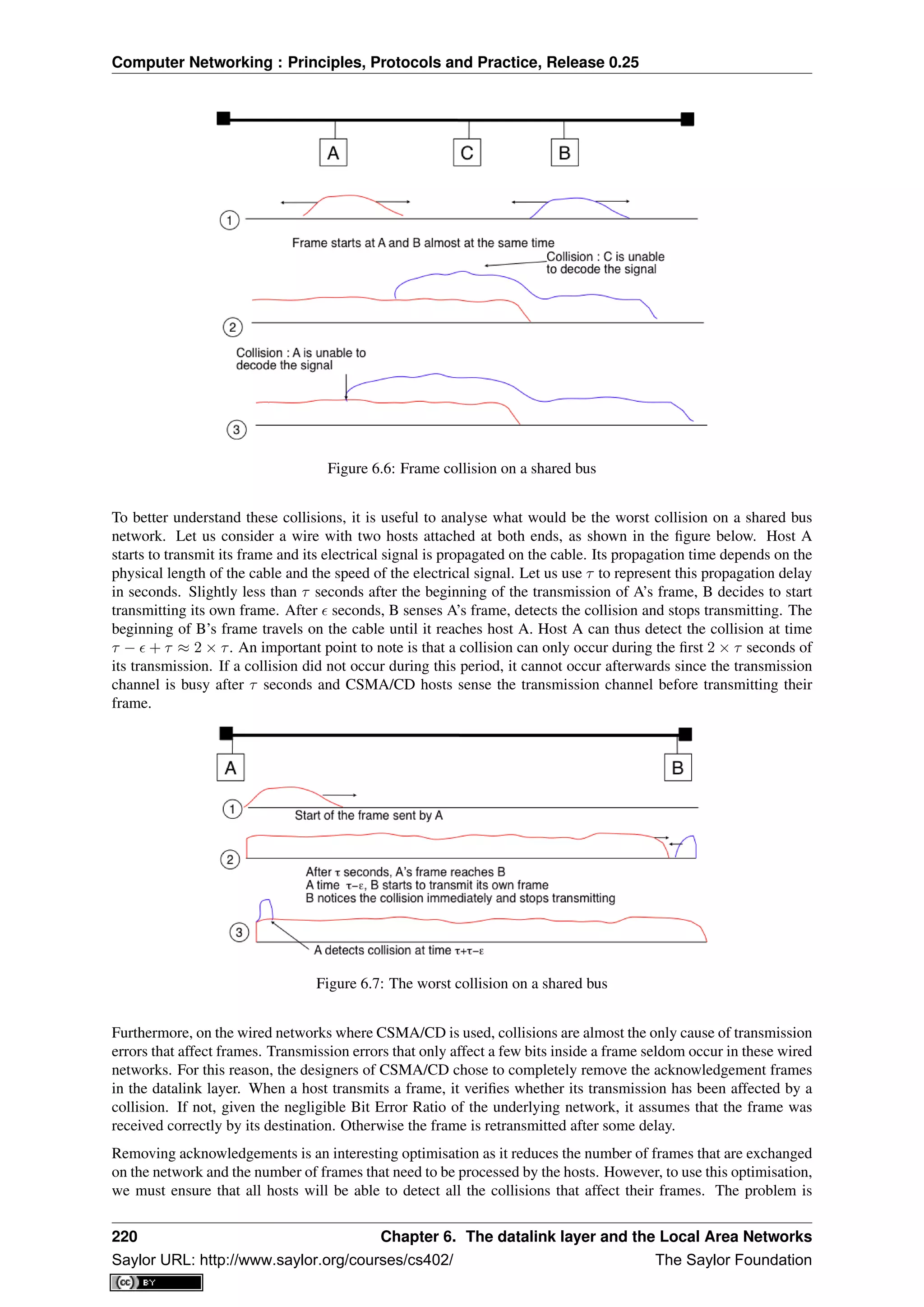
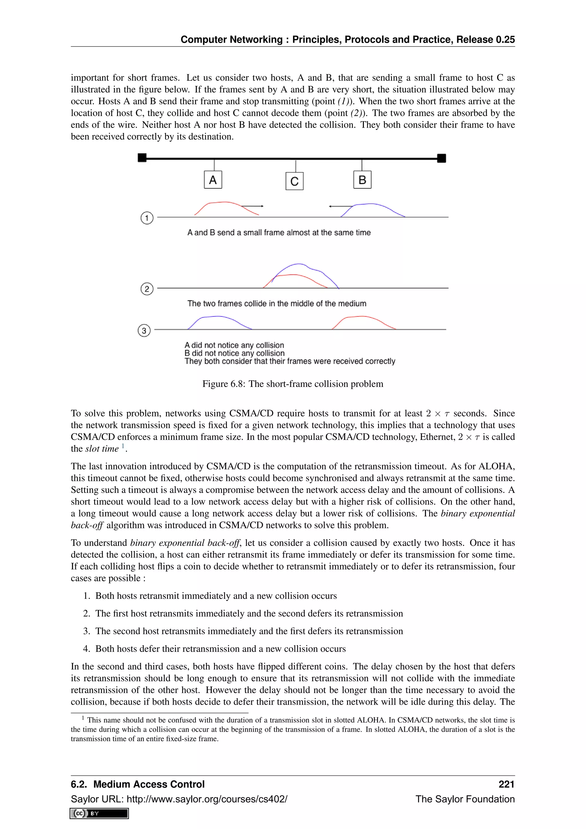
![Computer Networking : Principles, Protocols and Practice, Release 0.25
slot time is the optimal delay since it is the shortest delay that ensures that the first host will be able to retransmit
its frame completely without any collision.
If two hosts are competing, the algorithm above will avoid a second collision 50% of the time. However, if the
network is heavily loaded, several hosts may be competing at the same time. In this case, the hosts should be able
to automatically adapt their retransmission delay. The binary exponential back-off performs this adaptation based
on the number of collisions that have affected a frame. After the first collision, the host flips a coin and waits
0 or 1 slot time. After the second collision, it generates a random number and waits 0, 1, 2 or 3 slot times, etc.
The duration of the waiting time is doubled after each collision. The complete pseudo-code for the CSMA/CD
algorithm is shown in the figure below.
# CSMA/CD pseudo-code
N=1
while N<= max :
wait(channel_becomes_free)
send(frame)
wait_until (end_of_frame) or (collision)
if collision detected:
stop transmitting
send(jamming)
k = min (10, N)
r = random(0, 2k - 1) * slotTime
wait(r*slotTime)
N=N+1
else :
wait(inter-frame_delay)
break
# end of while loop
# Too many transmission attempts
The inter-frame delay used in this pseudo-code is a short delay corresponding to the time required by a network
adapter to switch from transmit to receive mode. It is also used to prevent a host from sending a continuous
stream of frames without leaving any transmission opportunities for other hosts on the network. This contributes
to the fairness of CSMA/CD. Despite this delay, there are still conditions where CSMA/CD is not completely fair
[RY1994]. Consider for example a network with two hosts : a server sending long frames and a client sending
acknowledgments. Measurements reported in [RY1994] have shown that there are situations where the client
could suffer from repeated collisions that lead it to wait for long periods of time due to the exponential back-off
algorithm.
6.2.5 Carrier Sense Multiple Access with Collision Avoidance
The Carrier Sense Multiple Access with Collision Avoidance (CSMA/CA) Medium Access Control algorithm was
designed for the popular WiFi wireless network technology [802.11]. CSMA/CA also senses the transmission
channel before transmitting a frame. Furthermore, CSMA/CA tries to avoid collisions by carefully tuning the
timers used by CSMA/CA devices.
CSMA/CA uses acknowledgements like CSMA. Each frame contains a sequence number and a CRC. The CRC
is used to detect transmission errors while the sequence number is used to avoid frame duplication. When a
device receives a correct frame, it returns a special acknowledgement frame to the sender. CSMA/CA introduces
a small delay, named Short Inter Frame Spacing (SIFS), between the reception of a frame and the transmission of
the acknowledgement frame. This delay corresponds to the time that is required to switch the radio of a device
between the reception and transmission modes.
Compared to CSMA, CSMA/CA defines more precisely when a device is allowed to send a frame. First,
CSMA/CA defines two delays : DIFS and EIFS. To send a frame, a device must first wait until the channel
has been idle for at least the Distributed Coordination Function Inter Frame Space (DIFS) if the previous frame
was received correctly. However, if the previously received frame was corrupted, this indicates that there are
collisions and the device must sense the channel idle for at least the Extended Inter Frame Space (EIFS), with
SIFS < DIFS < EIFS. The exact values for SIFS, DIFS and EIFS depend on the underlying physical layer
[802.11].
222 Chapter 6. The datalink layer and the Local Area Networks
Saylor URL: http://www.saylor.org/courses/cs402/ The Saylor Foundation](https://image.slidesharecdn.com/computer-networking-principles-bonaventure-1-30-31-otc1-150825141809-lva1-app6891/75/Computer-networking-principles-bonaventure-1-30-31-otc1-226-2048.jpg)
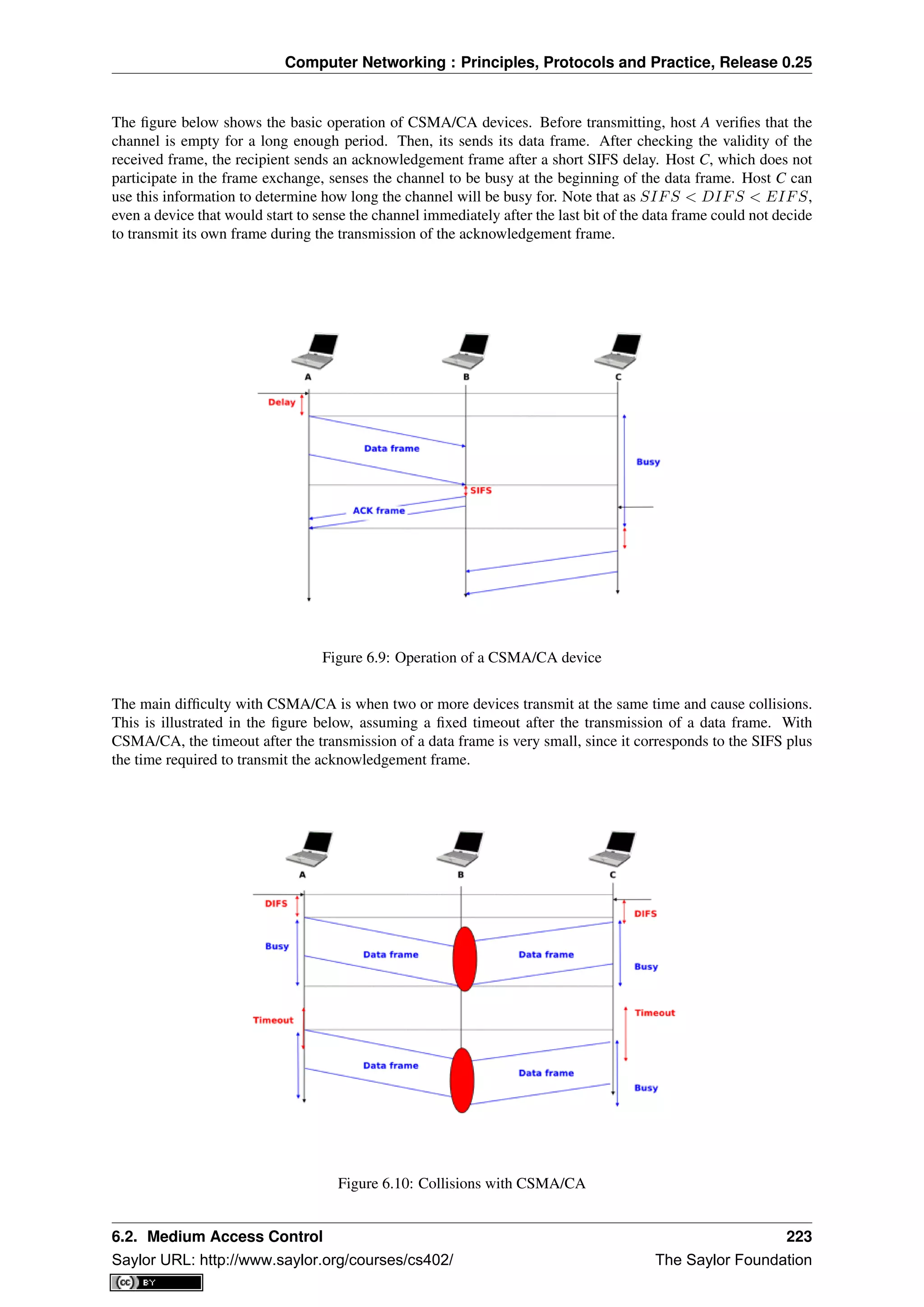
![Computer Networking : Principles, Protocols and Practice, Release 0.25
To deal with this problem, CSMA/CA relies on a backoff timer. This backoff timer is a random delay that is
chosen by each device in a range that depends on the number of retransmissions for the current frame. The
range grows exponentially with the retransmissions as in CSMA/CD. The minimum range for the backoff timer
is [0, 7 ∗ slotTime] where the slotTime is a parameter that depends on the underlying physical layer. Compared
to CSMA/CD’s exponential backoff, there are two important differences to notice. First, the initial range for
the backoff timer is seven times larger. This is because it is impossible in CSMA/CA to detect collisions as
they happen. With CSMA/CA, a collision may affect the entire frame while with CSMA/CD it can only affect
the beginning of the frame. Second, a CSMA/CA device must regularly sense the transmission channel during
its back off timer. If the channel becomes busy (i.e. because another device is transmitting), then the back off
timer must be frozen until the channel becomes free again. Once the channel becomes free, the back off timer
is restarted. This is in contrast with CSMA/CD where the back off is recomputed after each collision. This is
illustrated in the figure below. Host A chooses a smaller backoff than host C. When C senses the channel to be
busy, it freezes its backoff timer and only restarts it once the channel is free again.
Figure 6.11: Detailed example with CSMA/CA
The pseudo-code below summarises the operation of a CSMA/CA device. The values of the SIFS, DIFS, EIFS
and slotTime depend on the underlying physical layer technology [802.11]
# CSMA/CA simplified pseudo-code
N=1
while N<= max :
waitUntil(free(channel))
if correct(last_frame) :
wait(channel_free_during_t >=DIFS)
else:
wait(channel_free_during_t >=EIFS)
back-off_time = int(random[0,min(255,7*(2^(N-1)))])*slotTime
wait(channel free during backoff_time)
# backoff timer is frozen while channel is sensed to be busy
send(frame)
wait(ack or timeout)
if received(ack)
# frame received correctly
break
else:
# retransmission required
N=N+1
224 Chapter 6. The datalink layer and the Local Area Networks
Saylor URL: http://www.saylor.org/courses/cs402/ The Saylor Foundation](https://image.slidesharecdn.com/computer-networking-principles-bonaventure-1-30-31-otc1-150825141809-lva1-app6891/75/Computer-networking-principles-bonaventure-1-30-31-otc1-228-2048.jpg)
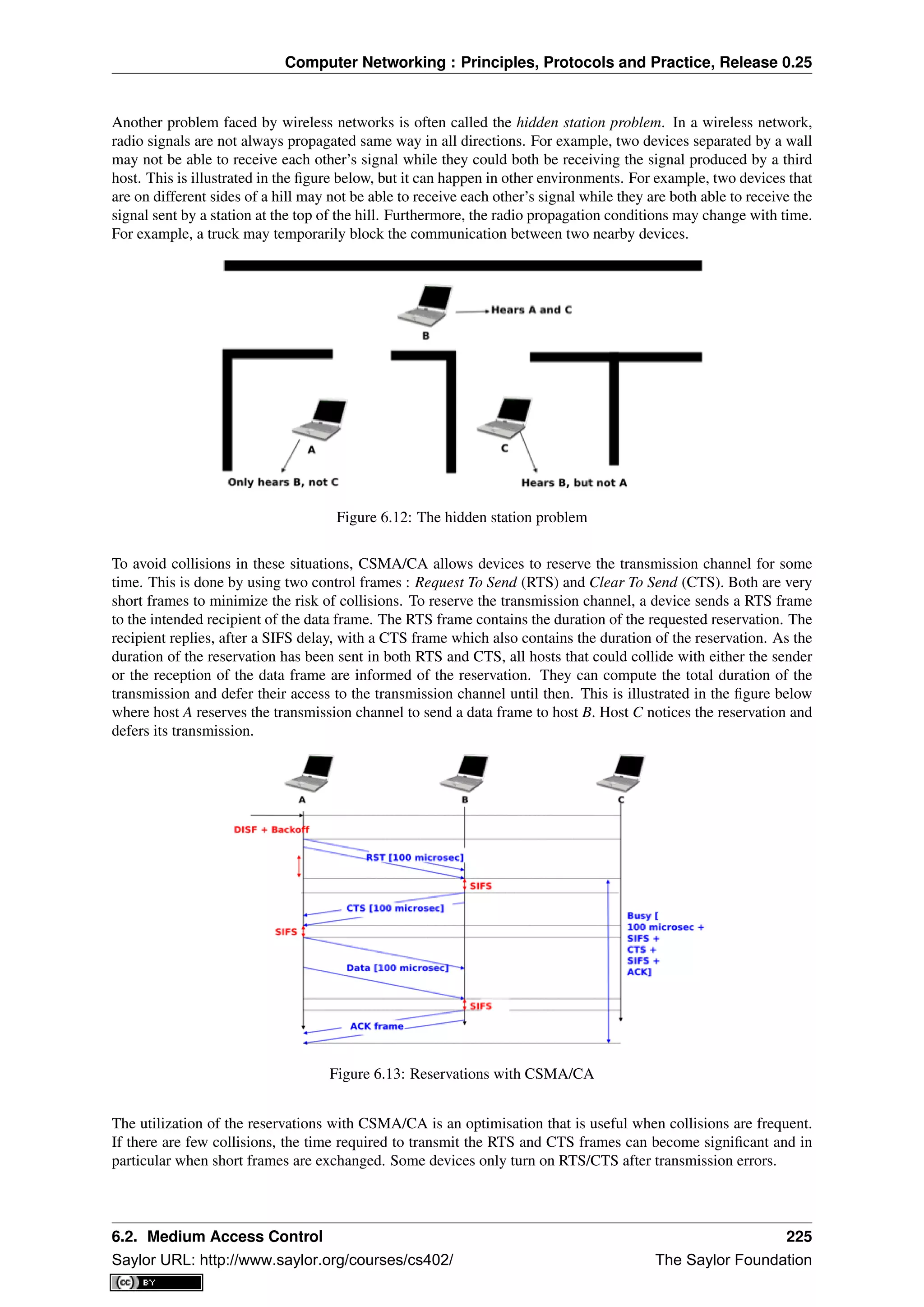
![Computer Networking : Principles, Protocols and Practice, Release 0.25
6.2.6 Deterministic Medium Access Control algorithms
During the 1970s and 1980s, there were huge debates in the networking community about the best suited Medium
Access Control algorithms for Local Area Networks. The optimistic algorithms that we have described until
now were relatively easy to implement when they were designed. From a performance perspective, mathematical
models and simulations showed the ability of these optimistic techniques to sustain load. However, none of the
optimistic techniques are able to guarantee that a frame will be delivered within a given delay bound and some
applications require predictable transmission delays. The deterministic MAC algorithms were considered by a
fraction of the networking community as the best solution to fulfill the needs of Local Area Networks.
Both the proponents of the deterministic and the opportunistic techniques lobbied to develop standards for Local
Area networks that would incorporate their solution. Instead of trying to find an impossible compromise between
these diverging views, the IEEE 802 committee that was chartered to develop Local Area Network standards
chose to work in parallel on three different LAN technologies and created three working groups. The IEEE
802.3 working group became responsible for CSMA/CD. The proponents of deterministic MAC algorithms agreed
on the basic principle of exchanging special frames called tokens between devices to regulate the access to the
transmission medium. However, they did not agree on the most suitable physical layout for the network. IBM
argued in favor of Ring-shaped networks while the manufacturing industry, led by General Motors, argued in
favor of a bus-shaped network. This led to the creation of the IEEE 802.4 working group to standardise Token Bus
networks and the IEEE 802.5 working group to standardise Token Ring networks. Although these techniques are
not widely used anymore today, the principles behind a token-based protocol are still important.
The IEEE 802.5 Token Ring technology is defined in [802.5]. We use Token Ring as an example to explain the
principles of the token-based MAC algorithms in ring-shaped networks. Other ring-shaped networks include the
almost defunct FDDI [Ross1989] or the more recent Resilient Pack Ring [DYGU2004] . A good survey of the
token ring networks may be found in [Bux1989] .
A Token Ring network is composed of a set of stations that are attached to a unidirectional ring. The basic principle
of the Token Ring MAC algorithm is that two types of frames travel on the ring : tokens and data frames. When the
Token Ring starts, one of the stations sends the token. The token is a small frame that represents the authorization
to transmit data frames on the ring. To transmit a data frame on the ring, a station must first capture the token by
removing it from the ring. As only one station can capture the token at a time, the station that owns the token can
safely transmit a data frame on the ring without risking collisions. After having transmitted its frame, the station
must remove it from the ring and resend the token so that other stations can transmit their own frames.
Figure 6.14: A Token Ring network
While the basic principles of the Token Ring are simple, there are several subtle implementation details that add
complexity to Token Ring networks. To understand these details let us analyse the operation of a Token Ring
interface on a station. A Token Ring interface serves three different purposes. Like other LAN interfaces, it must
be able to send and receive frames. In addition, a Token Ring interface is part of the ring, and as such, it must be
able to forward the electrical signal that passes on the ring even when its station is powered off.
When powered-on, Token Ring interfaces operate in two different modes : listen and transmit. When operating
in listen mode, a Token Ring interface receives an electrical signal from its upstream neighbour on the ring,
introduces a delay equal to the transmission time of one bit on the ring and regenerates the signal before sending
it to its downstream neighbour on the ring.
226 Chapter 6. The datalink layer and the Local Area Networks
Saylor URL: http://www.saylor.org/courses/cs402/ The Saylor Foundation](https://image.slidesharecdn.com/computer-networking-principles-bonaventure-1-30-31-otc1-150825141809-lva1-app6891/75/Computer-networking-principles-bonaventure-1-30-31-otc1-230-2048.jpg)
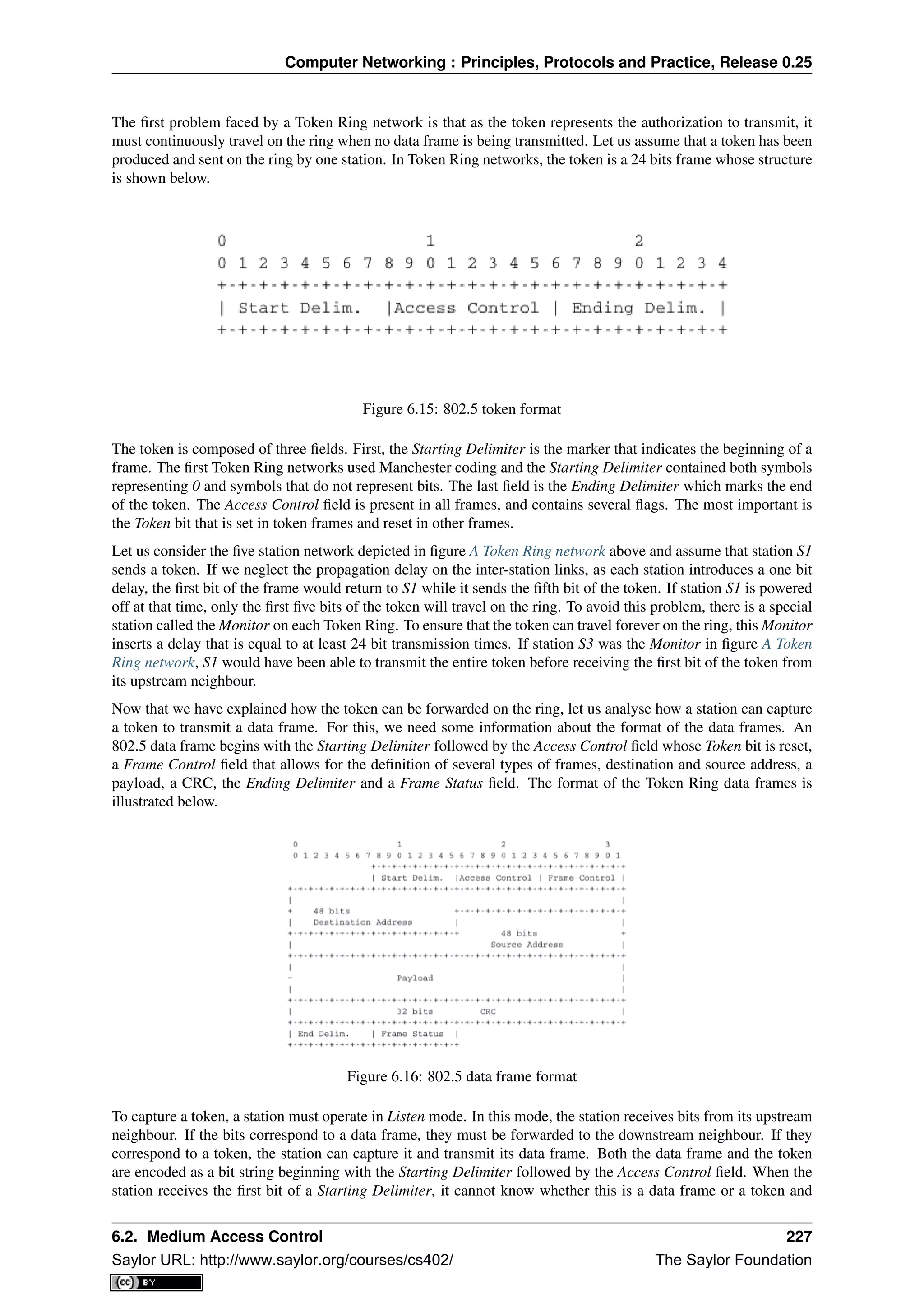
![Computer Networking : Principles, Protocols and Practice, Release 0.25
must forward the entire delimiter to its downstream neighbour. It is only when it receives the fourth bit of the
Access Control field (i.e. the Token bit) that the station knows whether the frame is a data frame or a token. If
the Token bit is reset, it indicates a data frame and the remaining bits of the data frame must be forwarded to the
downstream station. Otherwise (Token bit is set), this is a token and the station can capture it by resetting the
bit that is currently in its buffer. Thanks to this modification, the beginning of the token is now the beginning of
a data frame and the station can switch to Transmit mode and send its data frame starting at the fifth bit of the
Access Control field. Thus, the one-bit delay introduced by each Token Ring station plays a key role in enabling
the stations to efficiently capture the token.
After having transmitted its data frame, the station must remain in Transmit mode until it has received the last bit
of its own data frame. This ensures that the bits sent by a station do not remain in the network forever. A data
frame sent by a station in a Token Ring network passes in front of all stations attached to the network. Each station
can detect the data frame and analyse the destination address to possibly capture the frame.
The Frame Status field that appears after the Ending Delimiter is used to provide acknowledgements without
requiring special frames. The Frame Status contains two flags : A and C. Both flags are reset when a station sends
a data frame. These flags can be modified by their recipients. When a station senses its address as the destination
address of a frame, it can capture the frame, check its CRC and place it in its own buffers. The destination of
a frame must set the A bit (resp. C bit) of the Frame Status field once it has seen (resp. copied) a data frame.
By inspecting the Frame Status of the returning frame, the sender can verify whether its frame has been received
correctly by its destination.
The text above describes the basic operation of a Token Ring network when all stations work correctly. Unfor-
tunately, a real Token Ring network must be able to handle various types of anomalies and this increases the
complexity of Token Ring stations. We briefly list the problems and outline their solutions below. A detailed
description of the operation of Token Ring stations may be found in [802.5]. The first problem is when all the
stations attached to the network start. One of them must bootstrap the network by sending the first token. For this,
all stations implement a distributed election mechanism that is used to select the Monitor. Any station can become
a Monitor. The Monitor manages the Token Ring network and ensures that it operates correctly. Its first role is to
introduce a delay of 24 bit transmission times to ensure that the token can travel smoothly on the ring. Second,
the Monitor sends the first token on the ring. It must also verify that the token passes regularly. According to
the Token Ring standard [802.5], a station cannot retain the token to transmit data frames for a duration longer
than the Token Holding Time (THT) (slightly less than 10 milliseconds). On a network containing N stations, the
Monitor must receive the token at least every N × THT seconds. If the Monitor does not receive a token during
such a period, it cuts the ring for some time and then reinitialises the ring and sends a token.
Several other anomalies may occur in a Token Ring network. For example, a station could capture a token and
be powered off before having resent the token. Another station could have captured the token, sent its data frame
and be powered off before receiving all of its data frame. In this case, the bit string corresponding to the end of a
frame would remain in the ring without being removed by its sender. Several techniques are defined in [802.5] to
allow the Monitor to handle all these problems. If unfortunately, the Monitor fails, another station will be elected
to become the new Monitor.
6.3 Datalink layer technologies
In this section, we review the key characteristics of several datalink layer technologies. We discuss in more detail
the technologies that are widely used today. A detailed survey of all datalink layer technologies would be outside
the scope of this book.
6.3.1 The Point-to-Point Protocol
Many point-to-point datalink layers 2
have been developed, starting in the 1960s [McFadyen1976]. In this section,
we focus on the protocols that are often used to transport IP packets between hosts or routers that are directly
connected by a point-to-point link. This link can be a dedicated physical cable, a leased line through the telephone
network or a dial-up connection with modems on the two communicating hosts.
2 LAPB and HDLC were widely used datalink layer protocols.
228 Chapter 6. The datalink layer and the Local Area Networks
Saylor URL: http://www.saylor.org/courses/cs402/ The Saylor Foundation](https://image.slidesharecdn.com/computer-networking-principles-bonaventure-1-30-31-otc1-150825141809-lva1-app6891/75/Computer-networking-principles-bonaventure-1-30-31-otc1-232-2048.jpg)
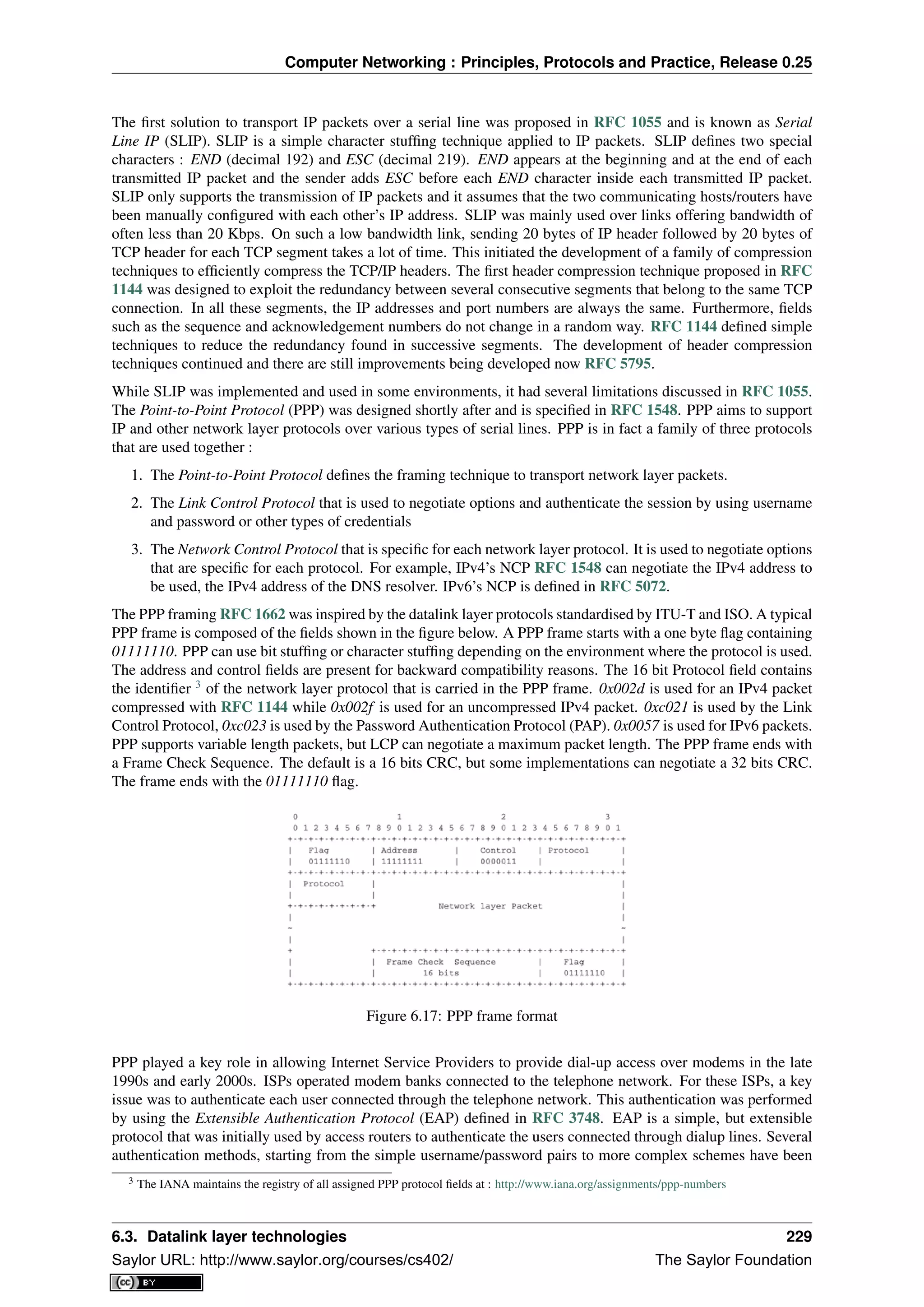
![Computer Networking : Principles, Protocols and Practice, Release 0.25
defined and implemented. When ISPs started to upgrade their physical infrastructure to provide Internet access
over Asymmetric Digital Subscriber Lines (ADSL), they tried to reuse their existing authentication (and billing)
systems. To meet these requirements, the IETF developed specifications to allow PPP frames to be transported over
other networks than the point-to-point links for which PPP was designed. Nowadays, most ADSL deployments
use PPP over either ATM RFC 2364 or Ethernet RFC 2516.
6.3.2 Ethernet
Ethernet was designed in the 1970s at the Palo Alto Research Center [Metcalfe1976]. The first prototype 4
used
a coaxial cable as the shared medium and 3 Mbps of bandwidth. Ethernet was improved during the late 1970s
and in the 1980s, Digital Equipment, Intel and Xerox published the first official Ethernet specification [DIX]. This
specification defines several important parameters for Ethernet networks. The first decision was to standardise
the commercial Ethernet at 10 Mbps. The second decision was the duration of the slot time. In Ethernet, a long
slot time enables networks to span a long distance but forces the host to use a larger minimum frame size. The
compromise was a slot time of 51.2 microseconds, which corresponds to a minimum frame size of 64 bytes.
The third decision was the frame format. The experimental 3 Mbps Ethernet network built at Xerox used short
frames containing 8 bit source and destination addresses fields, a 16 bit type indication, up to 554 bytes of payload
and a 16 bit CRC. Using 8 bit addresses was suitable for an experimental network, but it was clearly too small
for commercial deployments. Although the initial Ethernet specification [DIX] only allowed up to 1024 hosts on
an Ethernet network, it also recommended three important changes compared to the networking technologies that
were available at that time. The first change was to require each host attached to an Ethernet network to have a
globally unique datalink layer address. Until then, datalink layer addresses were manually configured on each host.
[DP1981] went against that state of the art and noted “Suitable installation-specific administrative procedures are
also needed for assigning numbers to hosts on a network. If a host is moved from one network to another it may
be necessary to change its host number if its former number is in use on the new network. This is easier said than
done, as each network must have an administrator who must record the continuously changing state of the system
(often on a piece of paper tacked to the wall !). It is anticipated that in future office environments, hosts locations
will change as often as telephones are changed in present-day offices.” The second change introduced by Ethernet
was to encode each address as a 48 bits field [DP1981]. 48 bit addresses were huge compared to the networking
technologies available in the 1980s, but the huge address space had several advantages [DP1981] including the
ability to allocate large blocks of addresses to manufacturers. Eventually, other LAN technologies opted for 48 bits
addresses as well [802]_ . The third change introduced by Ethernet was the definition of broadcast and multicast
addresses. The need for multicast Ethernet was foreseen in [DP1981] and thanks to the size of the addressing
space it was possible to reserve a large block of multicast addresses for each manufacturer.
The datalink layer addresses used in Ethernet networks are often called MAC addresses. They are structured as
shown in the figure below. The first bit of the address indicates whether the address identifies a network adapter
or a multicast group. The upper 24 bits are used to encode an Organisation Unique Identifier (OUI). This OUI
identifies a block of addresses that has been allocated by the secretariat 5
who is responsible for the uniqueness
of Ethernet addresses to a manufacturer. Once a manufacturer has received an OUI, it can build and sell products
with one of the 16 million addresses in this block.
Figure 6.18: 48 bits Ethernet address format
The original 10 Mbps Ethernet specification [DIX] defined a simple frame format where each frame is composed
of five fields. The Ethernet frame starts with a preamble (not shown in the figure below) that is used by the physical
layer of the receiver to synchronise its clock with the sender’s clock. The first field of the frame is the destination
4 Additional information about the history of the Ethernet technology may be found at http://ethernethistory.typepad.com/
5 Initially, the OUIs were allocated by Xerox [DP1981]. However, once Ethernet became an IEEE and later an ISO standard, the allocation
of the OUIs moved to IEEE. The list of all OUI allocations may be found at http://standards.ieee.org/regauth/oui/index.shtml
230 Chapter 6. The datalink layer and the Local Area Networks
Saylor URL: http://www.saylor.org/courses/cs402/ The Saylor Foundation](https://image.slidesharecdn.com/computer-networking-principles-bonaventure-1-30-31-otc1-150825141809-lva1-app6891/75/Computer-networking-principles-bonaventure-1-30-31-otc1-234-2048.jpg)
![Computer Networking : Principles, Protocols and Practice, Release 0.25
address. As this address is placed at the beginning of the frame, an Ethernet interface can quickly verify whether
it is the frame recipient and if not, cancel the processing of the arriving frame. The second field is the source
address. While the destination address can be either a unicast or a multicast/broadcast address, the source address
must always be a unicast address. The third field is a 16 bits integer that indicates which type of network layer
packet is carried inside the frame. This field is often called the EtherType. Frequently used EtherType values 6
include 0x0800 for IPv4, 0x86DD for IPv6 7
and 0x806 for the Address Resolution Protocol (ARP).
The fourth part of the Ethernet frame is the payload. The minimum length of the payload is 46 bytes to ensure a
minimum frame size, including the header of 512 bits. The Ethernet payload cannot be longer than 1500 bytes.
This size was found reasonable when the first Ethernet specification was written. At that time, Xerox had been
using its experimental 3 Mbps Ethernet that offered 554 bytes of payload and RFC 1122 required a minimum
MTU of 572 bytes for IPv4. 1500 bytes was large enough to support these needs without forcing the network
adapters to contain overly large memories. Furthermore, simulations and measurement studies performed in
Ethernet networks revealed that CSMA/CD was able to achieve a very high utilization. This is illustrated in the
figure below based on [SH1980], which shows the channel utilization achieved in Ethernet networks containing
different numbers of hosts that are sending frames of different sizes.
Figure 6.19: Impact of the frame length on the maximum channel utilisation [SH1980]
The last field of the Ethernet frame is a 32 bit Cyclical Redundancy Check (CRC). This CRC is able to catch a
much larger number of transmission errors than the Internet checksum used by IP, UDP and TCP [SGP98]. The
format of the Ethernet frame is shown below.
Note: Where should the CRC be located in a frame ?
The transport and datalink layers usually chose different strategies to place their CRCs or checksums. Transport
layer protocols usually place their CRCs or checksums in the segment header. Datalink layer protocols sometimes
place their CRC in the frame header, but often in a trailer at the end of the frame. This choice reflects implementa-
tion assumptions, but also influences performance RFC 893. When the CRC is placed in the trailer, as in Ethernet,
the datalink layer can compute it while transmitting the frame and insert it at the end of the transmission. All Eth-
ernet interfaces use this optimisation today. When the checksum is placed in the header, as in a TCP segment,
it is impossible for the network interface to compute it while transmitting the segment. Some network interfaces
provide hardware assistance to compute the TCP checksum, but this is more complex than if the TCP checksum
were placed in the trailer 8
.
6 The official list of all assigned Ethernet type values is available from http://standards.ieee.org/regauth/ethertype/eth.txt
7 The attentive reader may question the need for different EtherTypes for IPv4 and IPv6 while the IP header already contains a version
field that can be used to distinguish between IPv4 and IPv6 packets. Theoretically, IPv4 and IPv6 could have used the same EtherType.
Unfortunately, developers of the early IPv6 implementations found that some devices did not check the version field of the IPv4 packets that
they received and parsed frames whose EtherType was set to 0x0800 as IPv4 packets. Sending IPv6 packets to such devices would have caused
disruptions. To avoid this problem, the IETF decided to apply for a distinct EtherType value for IPv6.
8 These network interfaces compute the TCP checksum while a segment is transferred from the host memory to the network interface
6.3. Datalink layer technologies 231
Saylor URL: http://www.saylor.org/courses/cs402/ The Saylor Foundation](https://image.slidesharecdn.com/computer-networking-principles-bonaventure-1-30-31-otc1-150825141809-lva1-app6891/75/Computer-networking-principles-bonaventure-1-30-31-otc1-235-2048.jpg)
![Computer Networking : Principles, Protocols and Practice, Release 0.25
Figure 6.20: Ethernet DIX frame format
The Ethernet frame format shown above is specified in [DIX]. This is the format used to send both IPv4 RFC 894
and IPv6 packets RFC 2464. After the publication of [DIX], the Institute of Electrical and Electronic Engineers
(IEEE) began to standardise several Local Area Network technologies. IEEE worked on several LAN technolo-
gies, starting with Ethernet, Token Ring and Token Bus. These three technologies were completely different, but
they all agreed to use the 48 bits MAC addresses specified initially for Ethernet [802]_ . While developing its
Ethernet standard [802.3], the IEEE 802.3 working group was confronted with a problem. Ethernet mandated a
minimum payload size of 46 bytes, while some companies were looking for a LAN technology that could trans-
parently transport short frames containing only a few bytes of payload. Such a frame can be sent by an Ethernet
host by padding it to ensure that the payload is at least 46 bytes long. However since the Ethernet header [DIX]
does not contain a length field, it is impossible for the receiver to determine how many useful bytes were placed
inside the payload field. To solve this problem, the IEEE decided to replace the Type field of the Ethernet [DIX]
header with a length field 9
. This Length field contains the number of useful bytes in the frame payload. The pay-
load must still contain at least 46 bytes, but padding bytes are added by the sender and removed by the receiver.
In order to add the Length field without significantly changing the frame format, IEEE had to remove the Type
field. Without this field, it is impossible for a receiving host to identify the type of network layer packet inside a
received frame. To solve this new problem, IEEE developed a completely new sublayer called the Logical Link
Control [802.2]. Several protocols were defined in this sublayer. One of them provided a slightly different version
of the Type field of the original Ethernet frame format. Another contained acknowledgements and retransmissions
to provide a reliable service... In practice, [802.2] is never used to support IP in Ethernet networks. The figure
below shows the official [802.3] frame format.
Figure 6.21: Ethernet 802.3 frame format
Note: What is the Ethernet service ?
An Ethernet network provides an unreliable connectionless service. It supports three different transmission modes
[SH2004].
9 Fortunately, IEEE was able to define the [802.3] frame format while maintaining backward compatibility with the Ethernet [DIX] frame
format. The trick was to only assign values above 1500 as EtherType values. When a host receives a frame, it can determine whether the
frame’s format by checking its EtherType/Length field. A value lower smaller than 1501 is clearly a length indicator and thus an [802.3] frame.
A value larger than 1501 can only be type and thus a [DIX] frame.
232 Chapter 6. The datalink layer and the Local Area Networks
Saylor URL: http://www.saylor.org/courses/cs402/ The Saylor Foundation](https://image.slidesharecdn.com/computer-networking-principles-bonaventure-1-30-31-otc1-150825141809-lva1-app6891/75/Computer-networking-principles-bonaventure-1-30-31-otc1-236-2048.jpg)
![Computer Networking : Principles, Protocols and Practice, Release 0.25
[unicast, multicast and broadcast. While the Ethernet service is unreliable in theory, a good Ethernet
network should, in practice, provide a service that :]
• delivers frames to their destination with a very high probability of successful delivery
• does not reorder the transmitted frames
The first property is a consequence of the utilisation of CSMA/CD. The second property is a consequence of
the physical organisation of the Ethernet network as a shared bus. These two properties are important and all
evolutions of the Ethernet technology have preserved them.
Several physical layers have been defined for Ethernet networks. The first physical layer, usually called 10Base5,
provided 10 Mbps over a thick coaxial cable. The characteristics of the cable and the transceivers that were used
then enabled the utilisation of 500 meter long segments. A 10Base5 network can also include repeaters between
segments.
The second physical layer was 10Base2. This physical layer used a thin coaxial cable that was easier to install
than the 10Base5 cable, but could not be longer than 185 meters. A 10BaseF physical layer was also defined
to transport Ethernet over point-to-point optical links. The major change to the physical layer was the support
of twisted pairs in the 10BaseT specification. Twisted pair cables are traditionally used to support the telephone
service in office buildings. Most office buildings today are equipped with structured cabling. Several twisted pair
cables are installed between any room and a central telecom closet per building or per floor in large buildings.
These telecom closets act as concentration points for the telephone service but also for LANs.
The introduction of the twisted pairs led to two major changes to Ethernet. The first change concerns the physical
topology of the network. 10Base2 and 10Base5 networks are shared buses, the coaxial cable typically passes
through each room that contains a connected computer. A 10BaseT network is a star-shaped network. All the
devices connected to the network are attached to a twisted pair cable that ends in the telecom closet. From
a maintenance perspective, this is a major improvement. The cable is a weak point in 10Base2 and 10Base5
networks. Any physical damage on the cable broke the entire network and when such a failure occurred, the
network administrator had to manually check the entire cable to detect where it was damaged. With 10BaseT,
when one twisted pair is damaged, only the device connected to this twisted pair is affected and this does not
affect the other devices. The second major change introduced by 10BaseT was that is was impossible to build a
10BaseT network by simply connecting all the twisted pairs together. All the twisted pairs must be connected to
a relay that operates in the physical layer. This relay is called an Ethernet hub. A hub is thus a physical layer
relay that receives an electrical signal on one of its interfaces, regenerates the signal and transmits it over all its
other interfaces. Some hubs are also able to convert the electrical signal from one physical layer to another (e.g.
10BaseT to 10Base2 conversion).
Figure 6.22: Ethernet hubs in the reference model
Computers can directly be attached to Ethernet hubs. Ethernet hubs themselves can be attached to other Ethernet
hubs to build a larger network. However, some important guidelines must be followed when building a complex
network with hubs. First, the network topology must be a tree. As hubs are relays in the physical layer, adding
a link between Hub2 and Hub3 in the network below would create an electrical shortcut that would completely
disrupt the network. This implies that there cannot be any redundancy in a hub-based network. A failure of a
hub or of a link between two hubs would partition the network into two isolated networks. Second, as hubs are
relays in the physical layer, collisions can happen and must be handled by CSMA/CD as in a 10Base5 network.
This implies that the maximum delay between any pair of devices in the network cannot be longer than the 51.2
6.3. Datalink layer technologies 233
Saylor URL: http://www.saylor.org/courses/cs402/ The Saylor Foundation](https://image.slidesharecdn.com/computer-networking-principles-bonaventure-1-30-31-otc1-150825141809-lva1-app6891/75/Computer-networking-principles-bonaventure-1-30-31-otc1-237-2048.jpg)
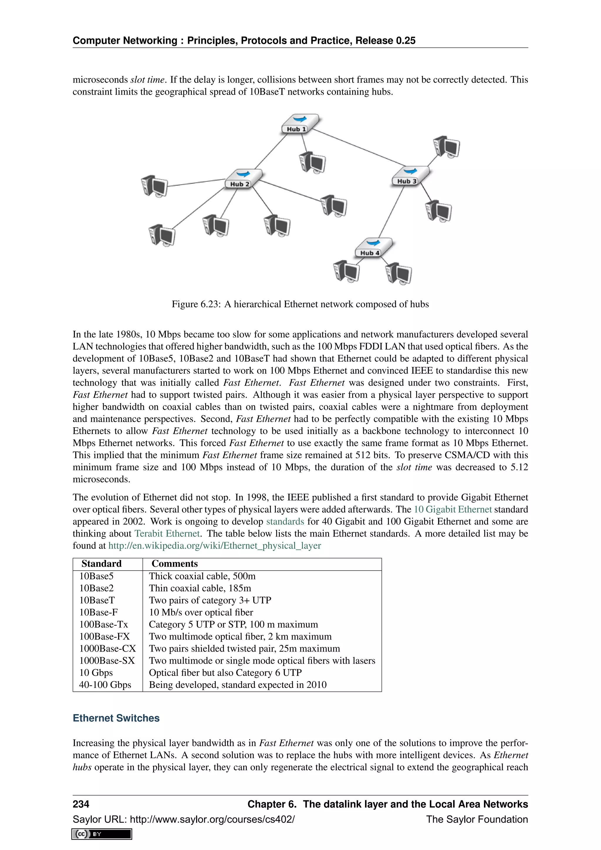
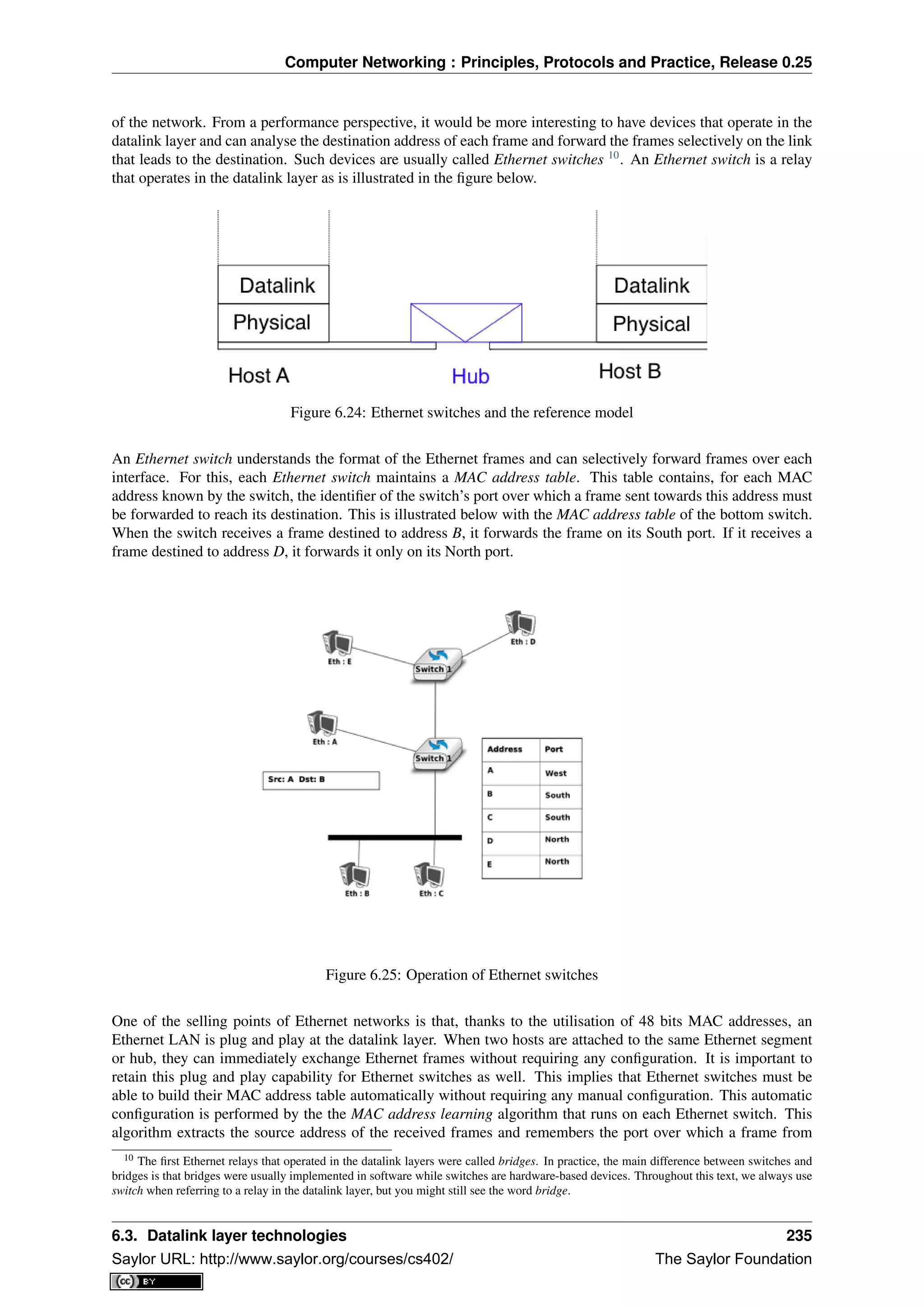
![Computer Networking : Principles, Protocols and Practice, Release 0.25
each source Ethernet address has been received. This information is inserted into the MAC address table that the
switch uses to forward frames. This allows the switch to automatically learn the ports that it can use to reach each
destination address, provided that this host has previously sent at least one frame. This is not a problem since
most upper layer protocols use acknowledgements at some layer and thus even an Ethernet printer sends Ethernet
frames as well.
The pseudo-code below details how an Ethernet switch forwards Ethernet frames. It first updates its MAC address
table with the source address of the frame. The MAC address table used by some switches also contains a
timestamp that is updated each time a frame is received from each known source address. This timestamp is
used to remove from the MAC address table entries that have not been active during the last n minutes. This limits
the growth of the MAC address table, but also allows hosts to move from one port to another. The switch uses its
MAC address table to forward the received unicast frame. If there is an entry for the frame’s destination address
in the MAC address table, the frame is forwarded selectively on the port listed in this entry. Otherwise, the switch
does not know how to reach the destination address and it must forward the frame on all its ports except the port
from which the frame has been received. This ensures that the frame will reach its destination, at the expense of
some unnecessary transmissions. These unnecessary transmissions will only last until the destination has sent its
first frame. Multicast and Broadcast frames are also forwarded in a similar way.
# Arrival of frame F on port P
# Table : MAC address table dictionary : addr->port
# Ports : list of all ports on the switch
src=F.SourceAddress
dst=F.DestinationAddress
Table[src]=P #src heard on port P
if isUnicast(dst) :
if dst in Table:
ForwardFrame(F,Table[dst])
else:
for o in Ports :
if o!= P : ForwardFrame(F,o)
else:
# multicast or broadcast destination
for o in Ports :
if o!= P : ForwardFrame(F,o)
Note: Security issues with Ethernet hubs and switches
From a security perspective, Ethernet hubs have the same drawbacks as the older coaxial cable. A host attached to
a hub will be able to capture all the frames exchanged between any pair of hosts attached to the same hub. Ethernet
switches are much better from this perspective thanks to the selective forwarding, a host will usually only receive
the frames destined to itself as well as the multicast, broadcast and unknown frames. However, this does not imply
that switches are completely secure. There are, unfortunately, attacks against Ethernet switches. From a security
perspective, the MAC address table is one of the fragile elements of an Ethernet switch. This table has a fixed
size. Some low-end switches can store a few tens or a few hundreds of addresses while higher-end switches can
store tens of thousands of addresses or more. From a security point of view, a limited resource can be the target
of Denial of Service attacks. Unfortunately, such attacks are also possible on Ethernet switches. A malicious
host could overflow the MAC address table of the switch by generating thousands of frames with random source
addresses. Once the MAC address table is full, the switch needs to broadcast all the frames that it receives. At
this point, an attacker will receive unicast frames that are not destined to its address. The ARP attack discussed in
the previous chapter could also occur with Ethernet switches [Vyncke2007]. Recent switches implement several
types of defences against these attacks, but they need to be carefully configured by the network administrator. See
[Vyncke2007] for a detailed discussion on security issues with Ethernet switches.
The MAC address learning algorithm combined with the forwarding algorithm work well in a tree-shaped network
such as the one shown above. However, to deal with link and switch failures, network administrators often add
redundant links to ensure that their network remains connected even after a failure. Let us consider what happens
in the Ethernet network shown in the figure below.
When all switches boot, their MAC address table is empty. Assume that host A sends a frame towards host C.
Upon reception of this frame, switch1 updates its MAC address table to remember that address A is reachable
236 Chapter 6. The datalink layer and the Local Area Networks
Saylor URL: http://www.saylor.org/courses/cs402/ The Saylor Foundation](https://image.slidesharecdn.com/computer-networking-principles-bonaventure-1-30-31-otc1-150825141809-lva1-app6891/75/Computer-networking-principles-bonaventure-1-30-31-otc1-240-2048.jpg)
![Computer Networking : Principles, Protocols and Practice, Release 0.25
Figure 6.26: Ethernet switches in a loop
via its West port. As there is no entry for address C in switch1’s MAC address table, the frame is forwarded to
both switch2 and switch3. When switch2 receives the frame, its updates its MAC address table for address A
and forwards the frame to host C as well as to switch3. switch3 has thus received two copies of the same frame.
As switch3 does not know how to reach the destination address, it forwards the frame received from switch1 to
switch2 and the frame received from switch2 to switch1... The single frame sent by host A will be continuously
duplicated by the switches until their MAC address table contains an entry for address C. Quickly, all the available
link bandwidth will be used to forward all the copies of this frame. As Ethernet does not contain any TTL or
HopLimit, this loop will never stop.
The MAC address learning algorithm allows switches to be plug-and-play. Unfortunately, the loops that arise
when the network topology is not a tree are a severe problem. Forcing the switches to only be used in tree-shaped
networks as hubs would be a severe limitation. To solve this problem, the inventors of Ethernet switches have
developed the Spanning Tree Protocol. This protocol allows switches to automatically disable ports on Ethernet
switches to ensure that the network does not contain any cycle that could cause frames to loop forever.
The Spanning Tree Protocol (802.1d)
The Spanning Tree Protocol (STP), proposed in [Perlman1985], is a distributed protocol that is used by switches
to reduce the network topology to a spanning tree, so that there are no cycles in the topology. For example,
consider the network shown in the figure below. In this figure, each bold line corresponds to an Ethernet to which
two Ethernet switches are attached. This network contains several cycles that must be broken to allow Ethernet
switches that are using the MAC address learning algorithm to exchange frames.
In this network, the STP will compute the following spanning tree. Switch1 will be the root of the tree. All the
interfaces of Switch1, Switch2 and Switch7 are part of the spanning tree. Only the interface connected to LANB
will be active on Switch9. LANH will only be served by Switch7 and the port of Switch44 on LANG will be
disabled. A frame originating on LANB and destined for LANA will be forwarded by Switch7 on LANC, then by
Switch1 on LANE, then by Switch44 on LANF and eventually by Switch2 on LANA.
Switches running the Spanning Tree Protocol exchange BPDUs. These BPDUs are always sent as frames with
destination MAC address as the ALL_BRIDGES reserved multicast MAC address. Each switch has a unique 64
bit identifier. To ensure uniqueness, the lower 48 bits of the identifier are set to the unique MAC address allocated
to the switch by its manufacturer. The high order 16 bits of the switch identifier can be configured by the network
administrator to influence the topology of the spanning tree. The default value for these high order bits is 32768.
6.3. Datalink layer technologies 237
Saylor URL: http://www.saylor.org/courses/cs402/ The Saylor Foundation](https://image.slidesharecdn.com/computer-networking-principles-bonaventure-1-30-31-otc1-150825141809-lva1-app6891/75/Computer-networking-principles-bonaventure-1-30-31-otc1-241-2048.jpg)
![Computer Networking : Principles, Protocols and Practice, Release 0.25
Figure 6.27: Spanning tree computed in a switched Ethernet network
The switches exchange BPDUs to build the spanning tree. Intuitively, the spanning tree is built by first selecting
the switch with the smallest identifier as the root of the tree. The branches of the spanning tree are then composed
of the shortest paths that allow all of the switches that compose the network to be reached. The BPDUs exchanged
by the switches contain the following information :
• the identifier of the root switch (R)
• the cost of the shortest path between the switch that sent the BPDU and the root switch (c)
• the identifier of the switch that sent the BPDU (T)
• the number of the switch port over which the BPDU was sent (p)
We will use the notation <R,c,T,p> to represent a BPDU whose root identifier is R, cost is c and that was sent
on the port p of switch T. The construction of the spanning tree depends on an ordering relationship among the
BPDUs. This ordering relationship could be implemented by the python function below.
# returns True if bpdu b1 is better than bpdu b2
def better( b1, b2) :
return ( (b1.R < b2.R) or
( (b1.R==b2.R) and (b1.c<b2.c) ) or
( (b1.R==b2.R) and (b1.c==b2.c) and (b1.T<b2.T) ) or
( (b1.R==b2.R) and (b1.c==b2.c) and (b1.T==b2.T) and (b1.p<b2.p) ) )
In addition to the identifier discussed above, the network administrator can also configure a cost to be associated
to each switch port. Usually, the cost of a port depends on its bandwidth and the [802.1d] standard recommends
the values below. Of course, the network administrator may choose other values. We will use the notation cost[p]
to indicate the cost associated to port p in this section.
Bandwidth Cost
10 Mbps 2000000
100 Mbps 200000
1 Gbps 20000
10 Gbps 2000
100 Gbps 200
The Spanning Tree Protocol uses its own terminology that we illustrate in the figure above. A switch port can be
in three different states : Root, Designated and Blocked. All the ports of the root switch are in the Designated
state. The state of the ports on the other switches is determined based on the BPDU received on each port.
The Spanning Tree Protocol uses the ordering relationship to build the spanning tree. Each switch listens to
BPDUs on its ports. When BPDU=<R,c,T,p> is received on port q, the switch computes the port’s priority
vector: V[q]=<R,c+cost[q],T,p,q> , where cost[q] is the cost associated to the port over which the BPDU was
238 Chapter 6. The datalink layer and the Local Area Networks
Saylor URL: http://www.saylor.org/courses/cs402/ The Saylor Foundation](https://image.slidesharecdn.com/computer-networking-principles-bonaventure-1-30-31-otc1-150825141809-lva1-app6891/75/Computer-networking-principles-bonaventure-1-30-31-otc1-242-2048.jpg)
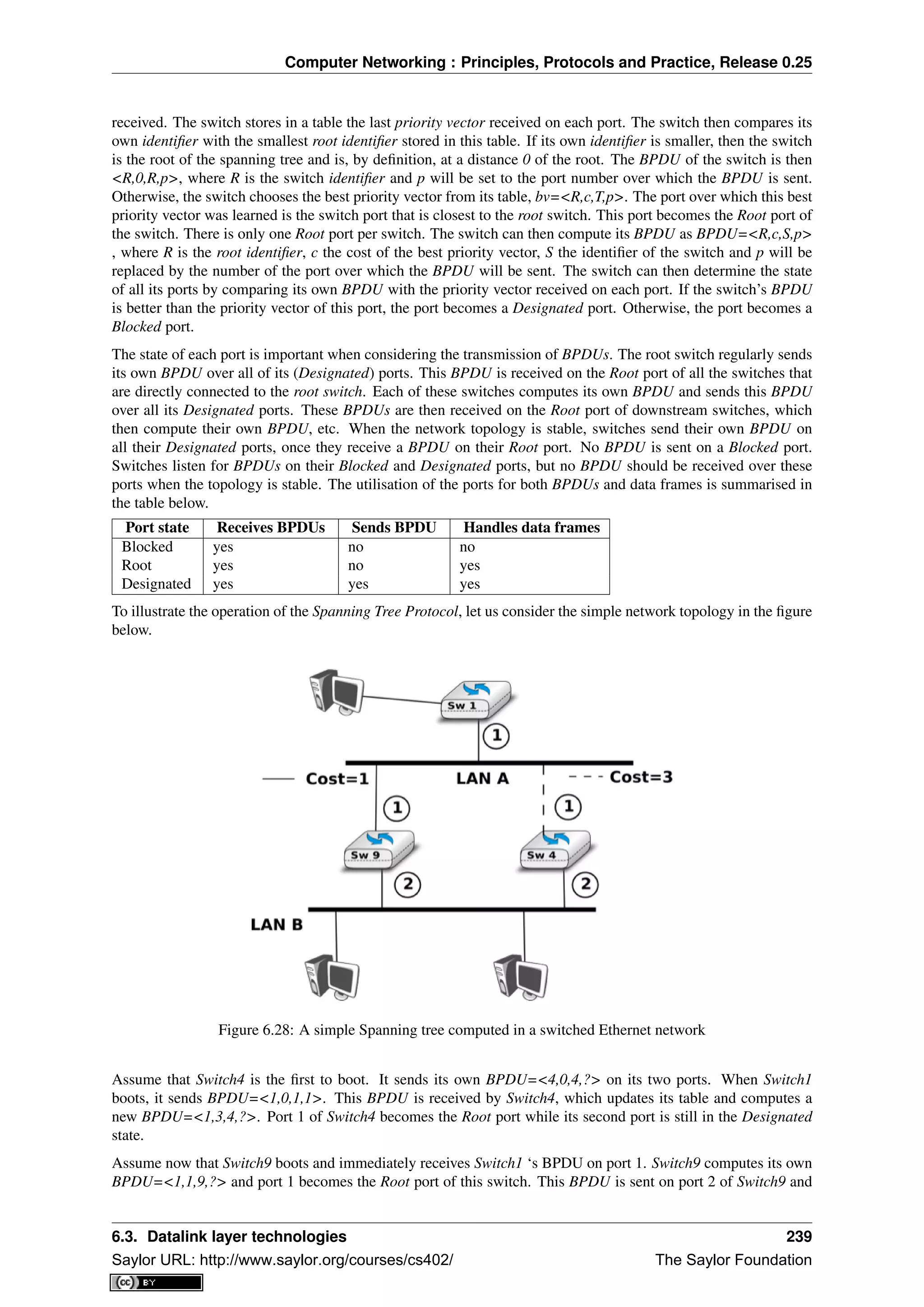
![Computer Networking : Principles, Protocols and Practice, Release 0.25
reaches Switch4. Switch4 compares the priority vector built from this BPDU (i.e. <1,2,9,2>) and notices that it is
better than Switch4 ‘s BPDU=<1,3,4,2>. Thus, port 2 becomes a Blocked port on Switch4.
During the computation of the spanning tree, switches discard all received data frames, as at that time the network
topology is not guaranteed to be loop-free. Once that topology has been stable for some time, the switches again
start to use the MAC learning algorithm to forward data frames. Only the Root and Designated ports are used
to forward data frames. Switches discard all the data frames received on their Blocked ports and never forward
frames on these ports.
Switches, ports and links can fail in a switched Ethernet network. When a failure occurs, the switches must be
able to recompute the spanning tree to recover from the failure. The Spanning Tree Protocol relies on regular
transmissions of the BPDUs to detect these failures. A BPDU contains two additional fields : the Age of the
BPDU and the Maximum Age. The Age contains the amount of time that has passed since the root switch initially
originated the BPDU. The root switch sends its BPDU with an Age of zero and each switch that computes its own
BPDU increments its Age by one. The Age of the BPDUs stored on a switch’s table is also incremented every
second. A BPDU expires when its Age reaches the Maximum Age. When the network is stable, this does not
happen as BPDU s are regularly sent by the root switch and downstream switches. However, if the root fails or
the network becomes partitioned, BPDU will expire and switches will recompute their own BPDU and restart the
Spanning Tree Protocol. Once a topology change has been detected, the forwarding of the data frames stops as
the topology is not guaranteed to be loop-free. Additional details about the reaction to failures may be found in
[802.1d]
Virtual LANs
Another important advantage of Ethernet switches is the ability to create Virtual Local Area Networks (VLANs).
A virtual LAN can be defined as a set of ports attached to one or more Ethernet switches. A switch can support
several VLANs and it runs one MAC learning algorithm for each Virtual LAN. When a switch receives a frame
with an unknown or a multicast destination, it forwards it over all the ports that belong to the same Virtual LAN
but not over the ports that belong to other Virtual LANs. Similarly, when a switch learns a source address on a
port, it associates it to the Virtual LAN of this port and uses this information only when forwarding frames on this
Virtual LAN.
The figure below illustrates a switched Ethernet network with three Virtual LANs. VLAN2 and VLAN3 only require
a local configuration of switch S1. Host C can exchange frames with host D, but not with hosts that are outside of
its VLAN. VLAN1 is more complex as there are ports of this VLAN on several switches. To support such VLANs,
local configuration is not sufficient anymore. When a switch receives a frame from another switch, it must be able
to determine the VLAN in which the frame originated to use the correct MAC table to forward the frame. This
is done by assigning an identifier to each Virtual LAN and placing this identifier inside the headers of the frames
that are exchanged between switches.
Figure 6.29: Virtual Local Area Networks in a switched Ethernet network
IEEE defined in the [802.1q] standard a special header to encode the VLAN identifiers. This 32 bit header
includes a 20 bit VLAN field that contains the VLAN identifier of each frame. The format of the [802.1q] header
is described below.
The [802.1q] header is inserted immediately after the source MAC address in the Ethernet frame (i.e. before the
EtherType field). The maximum frame size is increased by 4 bytes. It is encoded in 32 bits and contains four
240 Chapter 6. The datalink layer and the Local Area Networks
Saylor URL: http://www.saylor.org/courses/cs402/ The Saylor Foundation](https://image.slidesharecdn.com/computer-networking-principles-bonaventure-1-30-31-otc1-150825141809-lva1-app6891/75/Computer-networking-principles-bonaventure-1-30-31-otc1-244-2048.jpg)
![Computer Networking : Principles, Protocols and Practice, Release 0.25
Figure 6.30: Format of the 802.1q header
fields. The Tag Protocol Identifier is set to 0x8100 to allow the receiver to detect the presence of this additional
header. The Priority Code Point (PCP) is a three bit field that is used to support different transmission priorities
for the frame. Value 0 is the lowest priority and value 7 the highest. Frames with a higher priority can expect to
be forwarded earlier than frames having a lower priority. The C bit is used for compatibility between Ethernet and
Token Ring networks. The last 12 bits of the 802.1q header contain the VLAN identifier. Value 0 indicates that
the frame does not belong to any VLAN while value 0xFFF is reserved. This implies that 4094 different VLAN
identifiers can be used in an Ethernet network.
6.3.3 802.11 wireless networks
The radio spectrum is a limited resource that must be shared by everyone. During most of the twentieth century,
governments and international organisations have regulated most of the radio spectrum. This regulation controls
the utilisation of the radio spectrum, in order to ensure that there are no interferences between different users.
A company that wants to use a frequency range in a given region must apply for a license from the regulator.
Most regulators charge a fee for the utilisation of the radio spectrum and some governments have encouraged
competition among companies bidding for the same frequency to increase the license fees.
In the 1970s, after the first experiments with ALOHANet, interest in wireless networks grew. Many experiments
were done on and outside the ARPANet. One of these experiments was the first mobile phone , which was de-
veloped and tested in 1973. This experimental mobile phone was the starting point for the first generation analog
mobile phones. Given the growing demand for mobile phones, it was clear that the analog mobile phone technol-
ogy was not sufficient to support a large number of users. To support more users and new services, researchers in
several countries worked on the development of digital mobile telephones. In 1987, several European countries
decided to develop the standards for a common cellular telephone system across Europe : the Global System for
Mobile Communications (GSM). Since then, the standards have evolved and more than three billion users are
connected to GSM networks today.
While most of the frequency ranges of the radio spectrum are reserved for specific applications and require a
special licence, there are a few exceptions. These exceptions are known as the Industrial, Scientific and Medical
(ISM) radio bands. These bands can be used for industrial, scientific and medical applications without requiring
a licence from the regulator. For example, some radio-controlled models use the 27 MHz ISM band and some
cordless telephones operate in the 915 MHz ISM. In 1985, the 2.400-2.500 GHz band was added to the list of
ISM bands. This frequency range corresponds to the frequencies that are emitted by microwave ovens. Sharing
this band with licensed applications would have likely caused interferences, given the large number of microwave
ovens that are used. Despite the risk of interferences with microwave ovens, the opening of the 2.400-2.500 GHz
allowed the networking industry to develop several wireless network techniques to allow computers to exchange
data without using cables. In this section, we discuss in more detail the most popular one, i.e. the WiFi [802.11]
family of wireless networks. Other wireless networking techniques such as BlueTooth or HiperLAN use the same
frequency range.
Today, WiFi is a very popular wireless networking technology. There are more than several hundreds of millions
of WiFi devices. The development of this technology started in the late 1980s with the WaveLAN proprietary
wireless network. WaveLAN operated at 2 Mbps and used different frequency bands in different regions of the
world. In the early 1990s, the IEEE created the 802.11 working group to standardise a family of wireless network
technologies. This working group was very prolific and produced several wireless networking standards that use
different frequency ranges and different physical layers. The table below provides a summary of the main 802.11
standards.
6.3. Datalink layer technologies 241
Saylor URL: http://www.saylor.org/courses/cs402/ The Saylor Foundation](https://image.slidesharecdn.com/computer-networking-principles-bonaventure-1-30-31-otc1-150825141809-lva1-app6891/75/Computer-networking-principles-bonaventure-1-30-31-otc1-245-2048.jpg)
![Computer Networking : Principles, Protocols and Practice, Release 0.25
Standard Frequency Typical throughput Max bandwidth Range (m) indoor/outdoor
802.11 2.4 GHz 0.9 Mbps 2 Mbps 20/100
802.11a 5 GHz 23 Mbps 54 Mbps 35/120
802.11b 2.4 GHz 4.3 Mbps 11 Mbps 38/140
802.11g 2.4 GHz 19 Mbps 54 Mbps 38/140
802.11n 2.4/5 GHz 74 Mbps 150 Mbps 70/250
When developing its family of standards, the IEEE 802.11 working group took a similar approach as the IEEE
802.3 working group that developed various types of physical layers for Ethernet networks. 802.11 networks use
the CSMA/CA Medium Access Control technique described earlier and they all assume the same architecture and
use the same frame format.
The architecture of WiFi networks is slightly different from the Local Area Networks that we have discussed until
now. There are, in practice, two main types of WiFi networks : independent or adhoc networks and infrastructure
networks 11
. An independent or adhoc network is composed of a set of devices that communicate with each other.
These devices play the same role and the adhoc network is usually not connected to the global Internet. Adhoc
networks are used when for example a few laptops need to exchange information or to connect a computer with a
WiFi printer.
Figure 6.31: An 802.11 independent or adhoc network
Most WiFi networks are infrastructure networks. An infrastructure network contains one or more access points
that are attached to a fixed Local Area Network (usually an Ethernet network) that is connected to other networks
such as the Internet. The figure below shows such a network with two access points and four WiFi devices. Each
WiFi device is associated to one access point and uses this access point as a relay to exchange frames with the
devices that are associated to another access point or reachable through the LAN.
An 802.11 access point is a relay that operates in the datalink layer like switches. The figure below represents the
layers of the reference model that are involved when a WiFi host communicates with a host attached to an Ethernet
network through an access point.
802.11 devices exchange variable length frames, which have a slightly different structure than the simple frame
format used in Ethernet LANs. We review the key parts of the 802.11 frames. Additional details may be found
in [802.11] and [Gast2002] . An 802.11 frame contains a fixed length header, a variable length payload that
may contain up 2324 bytes of user data and a 32 bits CRC. Although the payload can contain up to 2324 bytes,
11 The 802.11 working group defined the basic service set (BSS) as a group of devices that communicate with each other. We continue to
use network when referring to a set of devices that communicate.
242 Chapter 6. The datalink layer and the Local Area Networks
Saylor URL: http://www.saylor.org/courses/cs402/ The Saylor Foundation](https://image.slidesharecdn.com/computer-networking-principles-bonaventure-1-30-31-otc1-150825141809-lva1-app6891/75/Computer-networking-principles-bonaventure-1-30-31-otc1-246-2048.jpg)
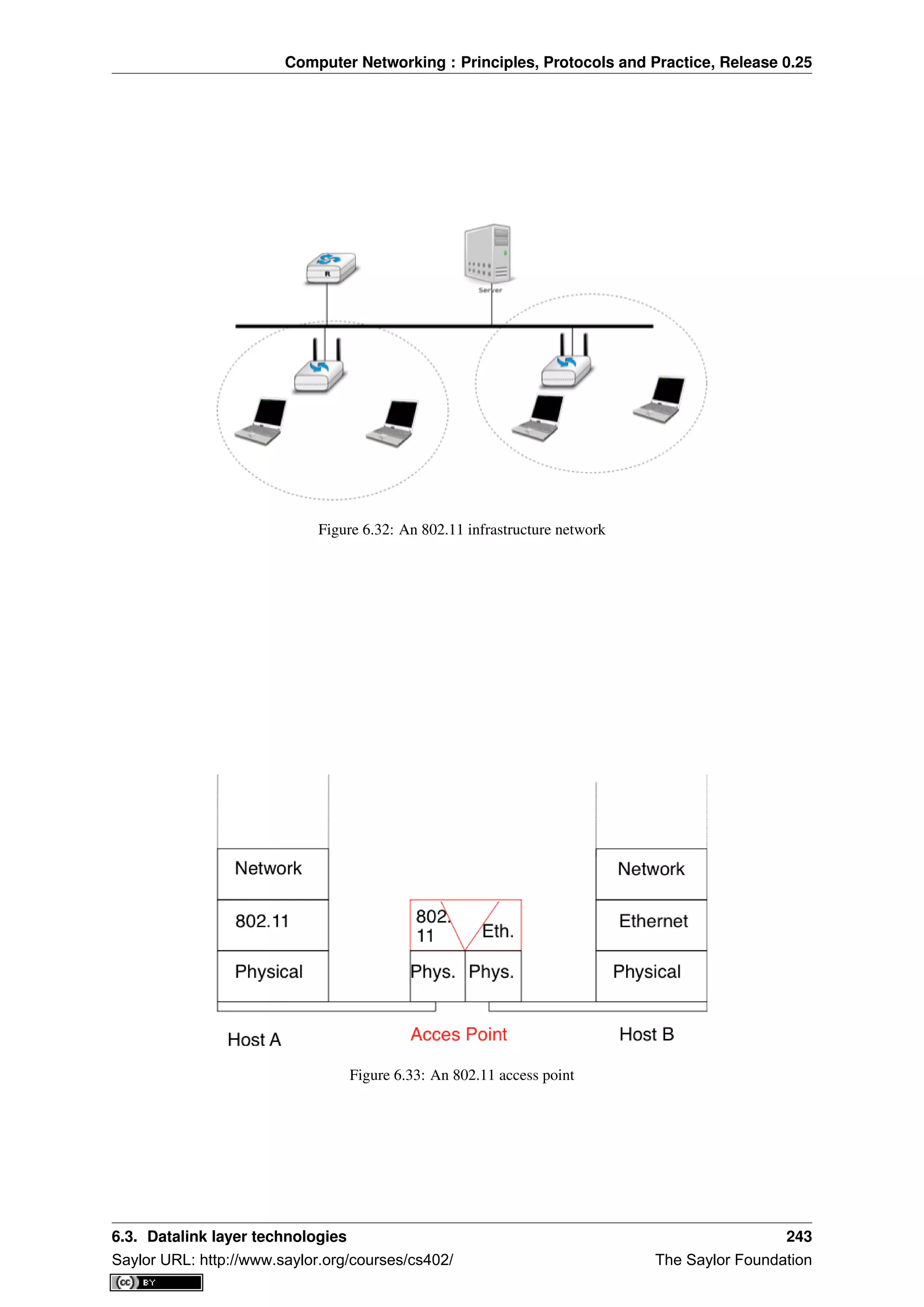
![Computer Networking : Principles, Protocols and Practice, Release 0.25
most 802.11 deployments use a maximum payload size of 1500 bytes as they are used in infrastructure networks
attached to Ethernet LANs. An 802.11 data frame is shown below.
Figure 6.34: 802.11 data frame format
The first part of the 802.11 header is the 16 bit Frame Control field. This field contains flags that indicate the
type of frame (data frame, RTS/CTS, acknowledgement, management frames, etc), whether the frame is sent to
or from a fixed LAN, etc [802.11]. The Duration is a 16 bit field that is used to reserve the transmission channel.
In data frames, the Duration field is usually set to the time required to transmit one acknowledgement frame after
a SIFS delay. Note that the Duration field must be set to zero in multicast and broadcast frames. As these frames
are not acknowledged, there is no need to reserve the transmission channel after their transmission. The Sequence
control field contains a 12 bits sequence number that is incremented for each data frame.
The astute reader may have noticed that the 802.11 data frames contain three 48-bits address fields 12
. This is
surprising compared to other protocols in the network and datalink layers whose headers only contain a source and
a destination address. The need for a third address in the 802.11 header comes from the infrastructure networks. In
such a network, frames are usually exchanged between routers and servers attached to the LAN and WiFi devices
attached to one of the access points. The role of the three address fields is specified by bit flags in the Frame
Control field.
When a frame is sent from a WiFi device to a server attached to the same LAN as the access point, the first address
of the frame is set to the MAC address of the access point, the second address is set to the MAC address of the
source WiFi device and the third address is the address of the final destination on the LAN. When the server
replies, it sends an Ethernet frame whose source address is its MAC address and the destination address is the
MAC address of the WiFi device. This frame is captured by the access point that converts the Ethernet header into
an 802.11 frame header. The 802.11 frame sent by the access point contains three addresses : the first address is
the MAC address of the destination WiFi device, the second address is the MAC address of the access point and
the third address the MAC address of the server that sent the frame.
802.11 control frames are simpler than data frames. They contain a Frame Control, a Duration field and one or
two addresses. The acknowledgement frames are very small. They only contain the address of the destination of
the acknowledgement. There is no source address and no Sequence Control field in the acknowledgement frames.
This is because the acknowledgement frame can easily be associated to the previous frame that it acknowledges.
Indeed, each unicast data frame contains a Duration field that is used to reserve the transmission channel to ensure
that no collision will affect the acknowledgement frame. The Sequence Control field is mainly used by the receiver
to remove duplicate frames. Duplicate frames are detected as follows. Each data frame contains a 12 bits Sequence
Control field and the Frame Control field contains the Retry bit flag that is set when a frame is transmitted. Each
802.11 receiver stores the most recent sequence number received from each source address in frames whose Retry
bit is reset. Upon reception of a frame with the Retry bit set, the receiver verifies its sequence number to determine
whether it is a duplicated frame or not.
802.11 RTS/CTS frames are used to reserve the transmission channel, in order to transmit one data frame and its
acknowledgement. The RTS frames contain a Duration and the transmitter and receiver addresses. The Duration
12 In fact, the [802.11] frame format contains a fourth optional address field. This fourth address is only used when an 802.11 wireless
network is used to interconnect bridges attached to two classical LAN networks.
244 Chapter 6. The datalink layer and the Local Area Networks
Saylor URL: http://www.saylor.org/courses/cs402/ The Saylor Foundation](https://image.slidesharecdn.com/computer-networking-principles-bonaventure-1-30-31-otc1-150825141809-lva1-app6891/75/Computer-networking-principles-bonaventure-1-30-31-otc1-248-2048.jpg)
![Computer Networking : Principles, Protocols and Practice, Release 0.25
Figure 6.35: IEEE 802.11 ACK and CTS frames
field of the RTS frame indicates the duration of the entire reservation (i.e. the time required to transmit the CTS,
the data frame, the acknowledgements and the required SIFS delays). The CTS frame has the same format as the
acknowledgement frame.
Figure 6.36: IEEE 802.11 RTS frame format
Note: The 802.11 service
Despite the utilization of acknowledgements, the 802.11 layer only provides an unreliable connectionless service
like Ethernet networks that do not use acknowledgements. The 802.11 acknowledgements are used to minimize
the probability of frame duplication. They do not guarantee that all frames will be correctly received by their
recipients. Like Ethernet, 802.11 networks provide a high probability of successful delivery of the frames, not a
guarantee. Furthermore, it should be noted that 802.11 networks do not use acknowledgements for multicast and
broadcast frames. This implies that in practice such frames are more likely to suffer from transmission errors than
unicast frames.
In addition to the data and control frames that we have briefly described above, 802.11 networks use several types
of management frames. These management frames are used for various purposes. We briefly describe some of
these frames below. A detailed discussion may be found in [802.11] and [Gast2002].
A first type of management frames are the beacon frames. These frames are broadcasted regularly by access
points. Each beacon frame contains information about the capabilities of the access point (e.g. the supported
802.11 transmission rates) and a Service Set Identity (SSID). The SSID is a null-terminated ASCII string that can
contain up to 32 characters. An access point may support several SSIDs and announce them in beacon frames. An
access point may also choose to remain silent and not advertise beacon frames. In this case, WiFi stations may
send Probe request frames to force the available access points to return a Probe response frame.
Note: IP over 802.11
Two types of encapsulation schemes were defined to support IP in Ethernet networks : the original encapsulation
scheme, built above the Ethernet DIX format is defined in RFC 894 and a second encapsulation RFC 1042
scheme, built above the LLC/SNAP protocol [802.2]. In 802.11 networks, the situation is simpler and only the
RFC 1042 encapsulation is used. In practice, this encapsulation adds 6 bytes to the 802.11 header. The first four
bytes correspond to the LLC/SNAP header. They are followed by the two bytes Ethernet Type field (0x800 for IP
and 0x806 for ARP). The figure below shows an IP packet encapsulated in an 802.11 frame.
The second important utilisation of the management frames is to allow a WiFi station to be associated with an
access point. When a WiFi station starts, it listens to beacon frames to find the available SSIDs. To be allowed to
6.3. Datalink layer technologies 245
Saylor URL: http://www.saylor.org/courses/cs402/ The Saylor Foundation](https://image.slidesharecdn.com/computer-networking-principles-bonaventure-1-30-31-otc1-150825141809-lva1-app6891/75/Computer-networking-principles-bonaventure-1-30-31-otc1-249-2048.jpg)
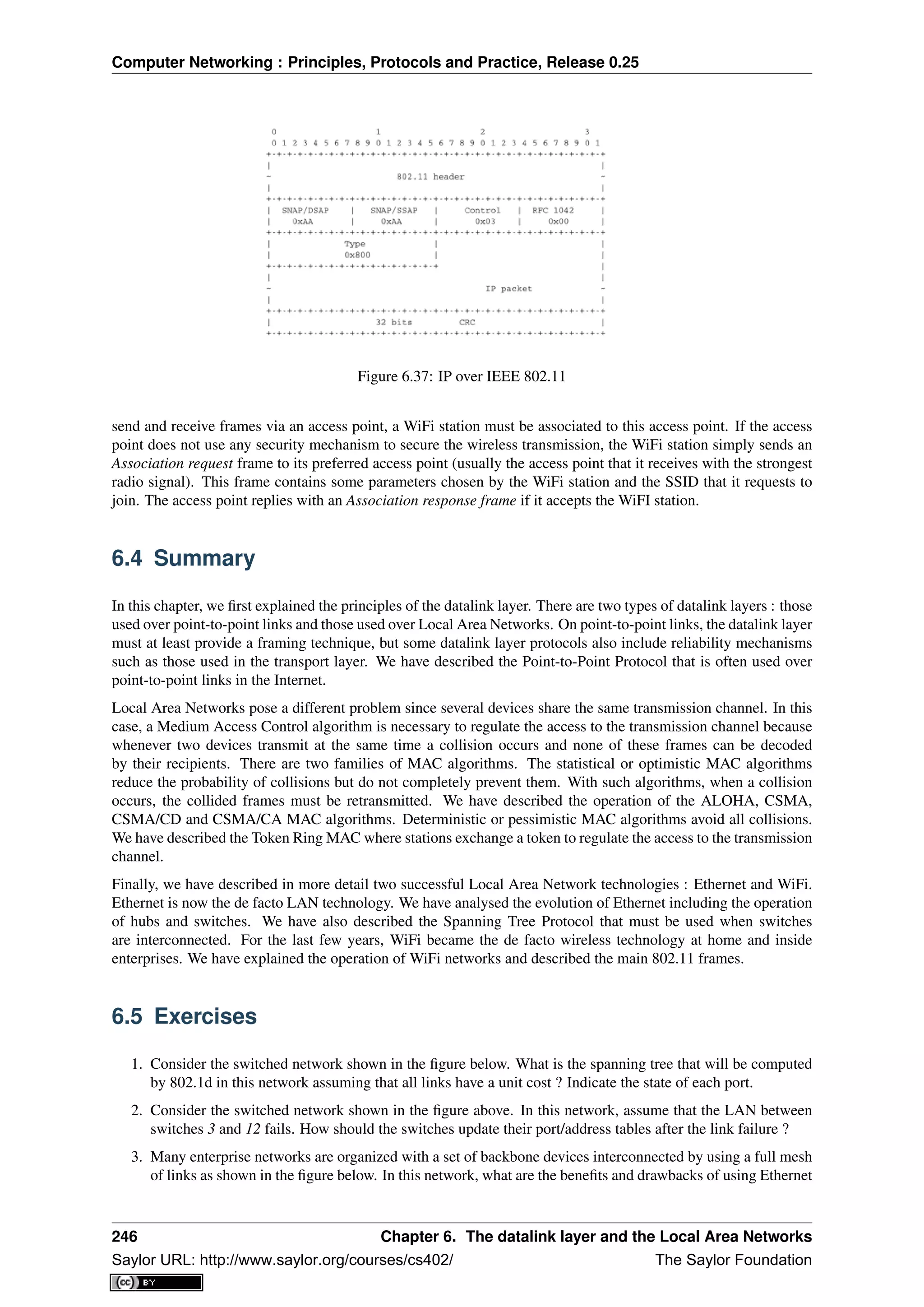
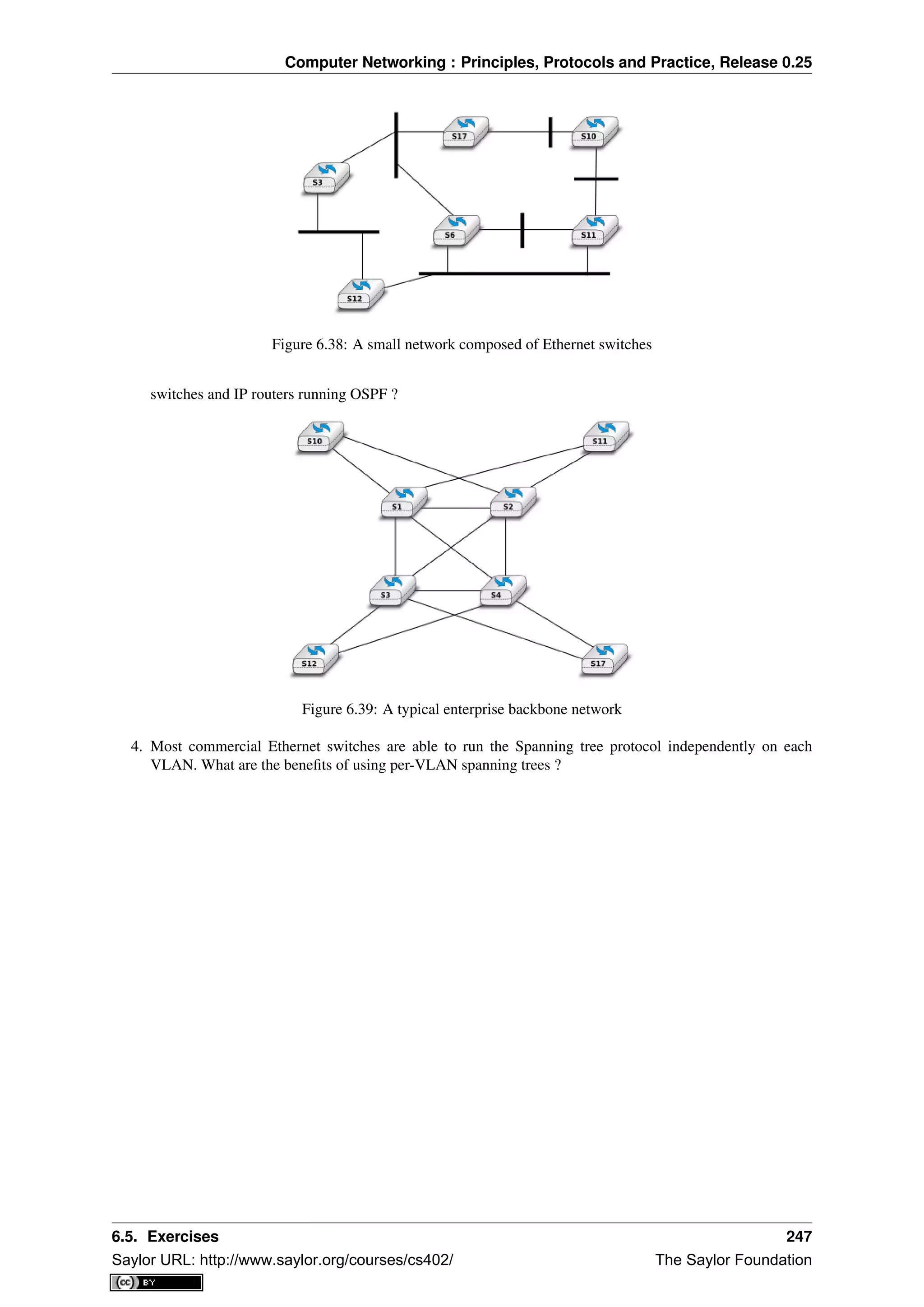

![Computer Networking : Principles, Protocols and Practice, Release 0.25
DNS The Domain Name System is a distributed database that can be queried by hosts to map names onto IP
addresses
eBGP An eBGP session is a BGP session between two directly connected routers that belong to two different
Autonomous Systems. Also called an external BGP session.
EGP Exterior Gateway Protocol. Synonym of interdomain routing protocol
EIGRP The Enhanced Interior Gateway Routing Protocol (EIGRP) is a proprietary intradomain routing protocol
that is often used in enterprise networks. EIGRP uses the DUAL algorithm described in [Garcia1993].
frame a frame is the unit of information transfer in the datalink layer
Frame-Relay A wide area networking technology using virtual circuits that is deployed by telecom operators.
ftp The File Transfer Protocol defined in RFC 959 has been the de facto protocol to exchange files over the
Internet before the widespread adoption of HTTP RFC 2616
FTP The File Transfer Protocol is defined in RFC 959
hosts.txt A file that initially contained the list of all Internet hosts with their IPv4 address. As the network grew,
this file was replaced by the DNS, but each host still maintains a small hosts.txt file that can be used when
DNS is not available.
HTML The HyperText Markup Language specifies the structure and the syntax of the documents that are ex-
changed on the world wide web. HTML is maintained by the HTML working group of the W3C
HTTP The HyperText Transport Protocol is defined in RFC 2616
hub A relay operating in the physical layer.
IANA The Internet Assigned Numbers Authority (IANA) is responsible for the coordination of the DNS Root,
IP addressing, and other Internet protocol resources
iBGP An iBGP session is a BGP between two routers belonging to the same Autonomous System. Also called
an internal BGP session.
ICANN The Internet Corporation for Assigned Names and Numbers (ICANN) coordinates the allocation of
domain names, IP addresses and AS numbers as well protocol parameters. It also coordinates the operation
and the evolution of the DNS root name servers.
IETF The Internet Engineering Task Force is a non-profit organisation that develops the standards for the proto-
cols used in the Internet. The IETF mainly covers the transport and network layers. Several application layer
protocols are also standardised within the IETF. The work in the IETF is organised in working groups. Most
of the work is performed by exchanging emails and there are three IETF meetings every year. Participation
is open to anyone. See http://www.ietf.org
IGP Interior Gateway Protocol. Synonym of intradomain routing protocol
IGRP The Interior Gateway Routing Protocol (IGRP) is a proprietary intradomain routing protocol that uses
distance vector. IGRP supports multiple metrics for each route but has been replaced by EIGRP
IMAP The Internet Message Access Protocol is defined in RFC 3501
IMAP The Internet Message Access Protocol (IMAP), defined in RFC 3501, is an application-level protocol
that allows a client to access and manipulate the emails stored on a server. With IMAP, the email messages
remain on the server and are not downloaded on the client.
Internet a public internet, i.e. a network composed of different networks that are running IPv4 or IPv6
internet an internet is an internetwork, i.e. a network composed of different networks. The Internet is a very
popular internetwork, but other internets have been used in the path.
inverse query For DNS servers and resolvers, an inverse query is a query for the domain name that corresponds
to a given IP address.
IP Internet Protocol is the generic term for the network layer protocol in the TCP/IP protocol suite. IPv4 is
widely used today and IPv6 is expected to replace IPv4
250 Chapter 7. Glossary
Saylor URL: http://www.saylor.org/courses/cs402/ The Saylor Foundation](https://image.slidesharecdn.com/computer-networking-principles-bonaventure-1-30-31-otc1-150825141809-lva1-app6891/75/Computer-networking-principles-bonaventure-1-30-31-otc1-254-2048.jpg)
![Computer Networking : Principles, Protocols and Practice, Release 0.25
IPv4 is the version 4 of the Internet Protocol, the connectionless network layer protocol used in most of the
Internet today. IPv4 addresses are encoded as a 32 bits field.
IPv6 is the version 6 of the Internet Protocol, the connectionless network layer protocol which is intended to
replace IPv4 . IPv6 addresses are encoded as a 128 bits field.
IS-IS Intermediate System- Intermediate System. A link-state intradomain routing that was initially defined for
the ISO CLNP protocol but was extended to support IPv4 and IPv6. IS-IS is often used in ISP networks. It
is defined in [ISO10589]
ISN The Initial Sequence Number of a TCP connection is the sequence number chosen by the client ( resp. server)
that is placed in the SYN (resp. SYN+ACK) segment during the establishment of the TCP connection.
ISO The International Standardization Organisation is an agency of the United Nations that is based in Geneva
and develop standards on various topics. Within ISO, country representatives vote to approve or reject stan-
dards. Most of the work on the development of ISO standards is done in expert working groups. Additional
information about ISO may be obtained from http://www.iso.int
ISO The International Standardization Organisation
ISO-3166 An ISO standard that defines codes to represent countries and their subdivisions. See
http://www.iso.org/iso/country_codes.htm
ISP An Internet Service Provider, i.e. a network that provides Internet access to its clients.
ITU The International Telecommunication Union is a United Nation’s agency whose purpose is to develop stan-
dards for the telecommunication industry. It was initially created to standardise the basic telephone system
but expanded later towards data networks. The work within ITU is mainly done by network specialists from
the telecommunication industry (operators and vendors). See http://www.itu.int for more information
IXP Internet eXchange Point. A location where routers belonging to different domains are attached to the same
Local Area Network to establish peering sessions and exchange packets. See http://www.euro-ix.net/ or
http://en.wikipedia.org/wiki/List_of_Internet_exchange_points_by_size for a partial list of IXPs.
LAN Local Area Network
leased line A telephone line that is permanently available between two endpoints.
MAN Metropolitan Area Network
MIME The Multipurpose Internet Mail Extensions (MIME) defined in RFC 2045 are a set of extensions to the
format of email messages that allow to use non-ASCII characters inside mail messages. A MIME message
can be composed of several different parts each having a different format.
MIME document A MIME document is a document, encoded by using the MIME format.
minicomputer A minicomputer is a multi-user system that was typically used in the 1960s/1970s
to serve departments. See the corresponding wikipedia article for additional information :
http://en.wikipedia.org/wiki/Minicomputer
modem A modem (modulator-demodulator) is a device that encodes (resp. decodes) digital information by mod-
ulating (resp. demodulating) an analog signal. Modems are frequently used to transmit digital information
over telephone lines and radio links. See http://en.wikipedia.org/wiki/Modem for a survey of various types
of modems
MSS A TCP option used by a TCP entity in SYN segments to indicate the Maximum Segment Size that it is able
to receive.
multicast a transmission mode where an information is sent efficiently to all the receivers that belong to a given
group
nameserver A server that implements the DNS protocol and can answer queries for names inside its own domain.
NAT A Network Address Translator is a middlebox that translates IP packets.
NBMA A Non Broadcast Mode Multiple Access Network is a subnetwork that supports multiple hosts/routers
but does not provide an efficient way of sending broadcast frames to all devices attached to the subnetwork.
ATM subnetworks are an example of NBMA networks.
251
Saylor URL: http://www.saylor.org/courses/cs402/ The Saylor Foundation](https://image.slidesharecdn.com/computer-networking-principles-bonaventure-1-30-31-otc1-150825141809-lva1-app6891/75/Computer-networking-principles-bonaventure-1-30-31-otc1-255-2048.jpg)
![Computer Networking : Principles, Protocols and Practice, Release 0.25
TCP/IP refers to the TCP and IP protocols
telnet The telnet protocol is defined in RFC 854
TLD A Top-level domain name. There are two types of TLDs. The ccTLD are the TLD that correspond to a two
letters ISO-3166 country code. The gTLD are the generic TLDs that are not assigned to a country.
TLS Transport Layer Security, defined in RFC 5246 is a cryptographic protocol that is used to provide commu-
nication security for Internet applications. This protocol is used on top of the transport service but a detailed
description is outside the scope of this book.
UDP User Datagram Protocol is a protocol of the transport layer in the TCP/IP protocol suite that provides an
unreliable connectionless service that includes a mechanism to detect corruption
unicast a transmission mode where an information is sent from one source to one recipient
vnc A networked application that allows to remotely access a computer’s Graphical User Interface. See
http://en.wikipedia.org/wiki/Virtual_Network_Computing
W3C The world wide web consortium was created to standardise the protocols and mechanisms used in the
global www. It is thus focused on a subset of the application layer. See http://www.w3c.org
WAN Wide Area Network
X.25 A wide area networking technology using virtual circuits that was deployed by telecom operators.
X11 The XWindow system and the associated protocols are defined in [SG1990]
XML The eXtensible Markup Language (XML) is a flexible text format derived from SGML. It was originally
designed for the electronic publishing industry but is now used by a wide variety of applications that need
to exchange structured data. The XML specifications are maintained by several working groups of the W3C
253
Saylor URL: http://www.saylor.org/courses/cs402/ The Saylor Foundation](https://image.slidesharecdn.com/computer-networking-principles-bonaventure-1-30-31-otc1-150825141809-lva1-app6891/75/Computer-networking-principles-bonaventure-1-30-31-otc1-257-2048.jpg)


![Bibliography
[802.11] LAN/MAN Standards Committee of the IEEE Computer Society. IEEE Standard for Information Tech-
nology - Telecommunications and information exchange between systems - local and metropolitan area net-
works - specific requirements - Part 11 : Wireless LAN Medium Access Control (MAC) and Physical Layer
(PHY) Specifications. IEEE, 1999.
[802.1d] LAN/MAN Standards Committee of the IEEE Computer Society, IEEE Standard for Local and
metropolitan area networks Media Access Control (MAC) Bridges , IEEE Std 802.1DTM-2004, 2004,
[802.1q] LAN/MAN Standards Committee of the IEEE Computer Society, IEEE Standard for Local and
metropolitan area networks— Virtual Bridged Local Area Networks, 2005,
[802.2] IEEE 802.2-1998 (ISO/IEC 8802-2:1998), IEEE Standard for Information technology–
Telecommunications and information exchange between systems–Local and metropoli-
tan area networks–Specific requirements–Part 2: Logical Link Control. Available from
http://standards.ieee.org/getieee802/802.2.html
[802.3] LAN/MAN Standards Committee of the IEEE Computer Society. IEEE Standard for Information
Technology - Telecommunications and information exchange between systems - local and metropoli-
tan area networks - specific requirements - Part 3 : Carrier Sense multiple access with collision
detection (CSMA/CD) access method and physical layer specification. IEEE, 2000. Available from
http://standards.ieee.org/getieee802/802.3.html
[802.5] LAN/MAN Standards Committee of the IEEE Computer Society. IEEE Standard for Information
technology–Telecommunications and information exchange between systems–Local and metropolitan area
networks–Specific requirements–Part 5: Token Ring Access Method and Physical Layer Specification. IEEE,
1998. available from http://standards.ieee.org/getieee802
[ACO+2006] Augustin, B., Cuvellier, X., Orgogozo, B., Viger, F., Friedman, T., Latapy, M., Magnien, C., Teix-
eira, R., Avoiding traceroute anomalies with Paris traceroute, Internet Measurement Conference, October
2006, See also http://www.paris-traceroute.net/
[AS2004] Androutsellis-Theotokis, S. and Spinellis, D.. 2004. A survey of peer-to-peer content distribution tech-
nologies. ACM Comput. Surv. 36, 4 (December 2004), 335-371.
[ATLAS2009] Labovitz, C., Iekel-Johnson, S., McPherson, D., Oberheide, J. and Jahanian, F., Internet inter-
domain traffic. In Proceedings of the ACM SIGCOMM 2010 conference on SIGCOMM (SIGCOMM ‘10).
ACM, New York, NY, USA, 75-86.
[AW05] Arlitt, M. and Williamson, C. 2005. An analysis of TCP reset behaviour on the internet. SIGCOMM
Comput. Commun. Rev. 35, 1 (Jan. 2005), 37-44.
259
Saylor URL: http://www.saylor.org/courses/cs402/ The Saylor Foundation](https://image.slidesharecdn.com/computer-networking-principles-bonaventure-1-30-31-otc1-150825141809-lva1-app6891/75/Computer-networking-principles-bonaventure-1-30-31-otc1-263-2048.jpg)
![Computer Networking : Principles, Protocols and Practice, Release 0.25
[Abramson1970] Abramson, N., THE ALOHA SYSTEM: another alternative for computer communications. In
Proceedings of the November 17-19, 1970, Fall Joint Computer Conference (Houston, Texas, November 17 -
19, 1970). AFIPS ‘70 (Fall). ACM, New York, NY, 281-285.
[B1989] Berners-Lee, T., Information Management: A Proposal, March 1989
[Baran] Baran, P., On distributed communications series, http://www.rand.org/about/history/baran.list.html,
[BE2007] Biondi, P. and A. Ebalard, IPv6 Routing Header Security, CanSecWest Security Conference 2007,
April 2007.
[BF1995] Bonomi, F. and Fendick, K.W., The rate-based flow control framework for the available bit rate ATM
service, IEEE Network, Mar/Apr 1995, Volume: 9, Issue: 2, pages : 25-39
[BG1992] Bertsekas, D., Gallager, G., Data networks, second edition, Prentice Hall, 1992
[BMO2006] Bhatia, M., Manral, V., Ohara, Y., IS-IS and OSPF Difference Discussions, work in progress, Internet
draft, Jan. 2006
[BMvB2009] Bagnulo, M., Matthews, P., van Beijnum, I., NAT64: Network Address and Protocol Translation
from IPv6 Clients to IPv4 Servers, Internet draft, work in progress, October 2009,
[BNT1997] Beech, W., Nielsen, D., Taylor, J., AX.25 Link Access Protocol for Amateur Packet Radio, version
‘2.2, Revision: July 1998
[BOP1994] Brakmo, L. S., O’Malley, S. W., and Peterson, L. L., TCP Vegas: new techniques for congestion
detection and avoidance. In Proceedings of the Conference on Communications Architectures, Protocols and
Applications (London, United Kingdom, August 31 - September 02, 1994). SIGCOMM ‘94. ACM, New York,
NY, 24-35.
[Benvenuti2005] Benvenuti, C., Understanding Linux Network Internals, O’Reilly Media, 2005
[Bush1945] Bush, V. As we may think The Atlantic Monthly 176 (July 1945), pp. 101–108
[Bush1993] Bush, R., FidoNet: technology, tools, and history. Commun. ACM 36, 8 (Aug. 1993), 31-35.
[Bux1989] Bux, W., Token-ring local-area networks and their performance, Proceedings of the IEEE, Vol 77, No
2, p. 238-259, Feb. 1989
[BYL2008] Buford, J., Yu, H., Lua, E.K., P2P Networking and Applications, Morgan Kaufmann, 2008
[CB2003] Cheswick, William R., Bellovin, Steven M., Rubin, Aviel D., Firewalls and internet security - Second
edition - Repelling the Wily Hacker, Addison-Wesley 2003
[CD2008] Calvert, K., Donahoo, M., TCP/IP Sockets in Java : Practical Guide for Programmers, Morgan Kauf-
man, 2008
[CJ1989] Chiu, D., Jain, R., Analysis of the Increase and Decrease Algorithms for Congestion Avoidance in
Computer Networks, Computer Networks and ISDN Systems Vol 17, pp 1-14, 1989
[CK74] Cerf, V., Kahn, R., A Protocol for Packet Network Intercommunication, IEEE Transactions on Commu-
nications, May 1974
[CNPI09] Gont, F., Security Assessment of the Transmission Control Protocol (TCP),Security Assessment of the
Transmission Control Protocol (TCP), Internet draft, work in progress, Jan. 2011
[COZ2008] Chi, Y., Oliveira, R., Zhang, L., Cyclops: The Internet AS-level Observatory, ACM SIGCOMM
Computer Communication Review (CCR), October 2008
[CSP2009] Carr, B., Sury, O., Palet Martinez, J., Davidson, A., Evans, R., Yilmaz, F., Wijte, Y., IPv6 Address
Allocation and Assignment Policy, RIPE document ripe-481, September 2009
[CT1980] Crane, R., Taft, E., Practical considerations in Ethernet local network design, Proc. of the 13th Hawaii
International Conference on Systems Sciences, Honolulu, January, 1980, pp. 166–174
[Cheshire2010] Cheshire, S., Connect-By-Name for IPv6, presentation at IETF 79th, November 2010
[Cheswick1990] Cheswick, B., An Evening with Berferd In Which a Cracker is Lured, Endured, and Studied,
Proc. Winter USENIX Conference, 1990, pp. 163-174
260 Bibliography
Saylor URL: http://www.saylor.org/courses/cs402/ The Saylor Foundation](https://image.slidesharecdn.com/computer-networking-principles-bonaventure-1-30-31-otc1-150825141809-lva1-app6891/75/Computer-networking-principles-bonaventure-1-30-31-otc1-264-2048.jpg)
![Computer Networking : Principles, Protocols and Practice, Release 0.25
[Clark88] Clark D., The Design Philosophy of the DARPA Internet Protocols, Computer Communications Re-
view 18:4, August 1988, pp. 106-114
[Comer1988] Comer, D., Internetworking with TCP/IP : principles, protocols & architecture, Prentice Hall, 1988
[Comer1991] Comer D., Internetworking With TCP/IP : Design Implementation and Internals, Prentice Hall,
1991
[Cohen1980] Cohen, D., On Holy Wars and a Plea for Peace, IEN 137, April 1980,
http://www.ietf.org/rfc/ien/ien137.txt
[DC2009] Donahoo, M., Calvert, K., TCP/IP Sockets in C: Practical Guide for Programmers , Morgan Kaufman,
2009,
[DIX] Digital, Intel, Xerox, The Ethernet: a local area network: data link layer and physical layer specifications.
SIGCOMM Comput. Commun. Rev. 11, 3 (Jul. 1981), 20-66.
[DKF+2007] Dimitropoulos, X., Krioukov, D., Fomenkov, M., Huffaker, B., Hyun, Y., Claffy, K., Riley, G., AS
Relationships: Inference and Validation, ACM SIGCOMM Computer Communication Review (CCR), Jan.
2007
[DP1981] Dalal, Y. K. and Printis, R. S., 48-bit absolute internet and Ethernet host numbers. In Proceedings of
the Seventh Symposium on Data Communications (Mexico City, Mexico, October 27 - 29, 1981). SIGCOMM
‘81. ACM, New York, NY, 240-245.
[Dunkels2003] Dunkels, A., Full TCP/IP for 8-Bit Architectures. In Proceedings of the first international confer-
ence on mobile applications, systems and services (MOBISYS 2003), San Francisco, May 2003.
[DT2007] Donnet, B. and Friedman, T., Internet Topology Discovery: a Survey. IEEE Communications Surveys
and Tutorials, 9(4):2-15, December 2007
[DYGU2004] Davik, F. Yilmaz, M. Gjessing, S. Uzun, N., IEEE 802.17 resilient packet ring tutorial, IEEE
Communications Magazine, Mar 2004, Vol 42, N 3, p. 112-118
[Dijkstra1959] Dijkstra, E., A Note on Two Problems in Connection with Graphs. Numerische Mathematik,
1:269- 271, 1959
[FDDI] ANSI. Information systems - Fiber Distributed Data Interface (FDDI) - token ring media access control
(MAC). ANSI X3.139-1987 (R1997), 1997
[Fletcher1982] Fletcher, J., An Arithmetic Checksum for Serial Transmissions, Communications, IEEE Transac-
tions on, Jan. 1982, Vol. 30, N. 1, pp. 247-252
[FFEB2005] Francois, P., Filsfils, C., Evans, J., and Bonaventure, O., Achieving sub-second IGP convergence in
large IP networks. SIGCOMM Comput. Commun. Rev. 35, 3 (Jul. 2005), 35-44.
[FJ1994] Floyd, S., and Jacobson, V., The Synchronization of Periodic Routing Messages, IEEE/ACM Transac-
tions on Networking, V.2 N.2, p. 122-136, April 1994
[FLM2008] Fuller, V., Lear, E., Meyer, D., Reclassifying 240/4 as usable unicast address space, Internet draft,
March 2008, workin progress
[FRT2002] Fortz, B. Rexford, J. ,Thorup, M., Traffic engineering with traditional IP routing protocols, IEEE
Communication Magazine, October 2002
[FTY99] Theodore Faber, Joe Touch, and Wei Yue, The TIME-WAIT state in TCP and Its Effect on Busy Servers,
Proc. Infocom ‘99, pp. 1573
[Feldmeier95] Feldmeier, D. C., Fast software implementation of error detection codes. IEEE/ACM Trans. Netw.
3, 6 (Dec. 1995), 640-651.
[GAVE1999] Govindan, R., Alaettinoglu, C., Varadhan, K., Estrin, D., An Architecture for Stable, Analyzable
Internet Routing, IEEE Network Magazine, Vol. 13, No. 1, pp. 29–35, January 1999
[GC2000] Grier, D., Campbell, M., A social history of Bitnet and Listserv, 1985-1991, Annals of the History of
Computing, IEEE, Volume 22, Issue 2, Apr-Jun 2000, pp. 32 - 41
[Genilloud1990] Genilloud, G., X.400 MHS: first steps towards an EDI communication standard. SIGCOMM
Comput. Commun. Rev. 20, 2 (Apr. 1990), 72-86.
Bibliography 261
Saylor URL: http://www.saylor.org/courses/cs402/ The Saylor Foundation](https://image.slidesharecdn.com/computer-networking-principles-bonaventure-1-30-31-otc1-150825141809-lva1-app6891/75/Computer-networking-principles-bonaventure-1-30-31-otc1-265-2048.jpg)
![Computer Networking : Principles, Protocols and Practice, Release 0.25
[GGR2001] Gao, L., Griffin, T., Rexford, J., Inherently safe backup routing with BGP, Proc. IEEE INFOCOM,
April 2001
[GR2001] Gao, L., Rexford, J., Stable Internet routing without global coordination, IEEE/ACM Transactions on
Networking, December 2001, pp. 681-692
[GSW2002] Griffin, T. G., Shepherd, F. B., and Wilfong, G., The stable paths problem and interdomain routing.
IEEE/ACM Trans. Netw. 10, 2 (Apr. 2002), 232-243
[GW1999] Griffin, T. G. and Wilfong, G., An analysis of BGP convergence properties. SIGCOMM Comput.
Commun. Rev. 29, 4 (Oct. 1999), 277-288.
[GW2002] Griffin, T. and Wilfong, G. T., Analysis of the MED Oscillation Problem in BGP. In Proceedings of the
10th IEEE international Conference on Network Protocols (November 12 - 15, 2002). ICNP. IEEE Computer
Society, Washington, DC, 90-99
[Garcia1993] Garcia-Lunes-Aceves, J., Loop-Free Routing Using Diffusing Computations, IEEE/ACM Transac-
tions on Networking, Vol. 1, No, 1, Feb. 1993
[Gast2002] Gast, M., 802.11 Wireless Networks : The Definitive Guide, O’Reilly, 2002
[Gill2004] Gill, V. , Lack of Priority Queuing Considered Harmful, ACM Queue, December 2004
[Goralski2009] Goralski, W., The Illustrated network : How TCP/IP works in a modern network, Morgan Kauf-
mann, 2009
[HFPMC2002] Huffaker, B., Fomenkov, M., Plummer, D., Moore, D., Claffy, K., Distance Metrics in the Internet,
Presented at the IEEE International Telecommunications Symposium (ITS) in 2002.
[HRX2008] Ha, S., Rhee, I., and Xu, L., CUBIC: a new TCP-friendly high-speed TCP variant. SIGOPS Oper.
Syst. Rev. 42, 5 (Jul. 2008), 64-74.
[ISO10589] Information technology — Telecommunications and information exchange between systems — In-
termediate System to Intermediate System intra-domain routeing information exchange protocol for use in
conjunction with the protocol for providing the connectionless-mode network service (ISO 8473), 2002
[Jacobson1988] Jacobson, V., Congestion avoidance and control. In Symposium Proceedings on Communica-
tions Architectures and Protocols (Stanford, California, United States, August 16 - 18, 1988). V. Cerf, Ed.
SIGCOMM ‘88. ACM, New York, NY, 314-329.
[JSBM2002] Jung, J., Sit, E., Balakrishnan, H., and Morris, R. 2002. DNS performance and the effectiveness of
caching. IEEE/ACM Trans. Netw. 10, 5 (Oct. 2002), 589-603.
[Kerrisk2010] Kerrisk, M., The Linux Programming Interface, No Starch Press, 2010
[KM1995] Kent, C. A. and Mogul, J. C., Fragmentation considered harmful. SIGCOMM Comput. Commun. Rev.
25, 1 (Jan. 1995), 75-87.
[KP91] Karn, P. and Partridge, C., Improving round-trip time estimates in reliable transport protocols. ACM
Trans. Comput. Syst. 9, 4 (Nov. 1991), 364-373.
[KPD1985] Karn, P., Price, H., Diersing, R., Packet radio in amateur service, IEEE Journal on Selected Areas in
Communications, 3, May, 1985
[KPS2003] Kaufman, C., Perlman, R., and Sommerfeld, B. DoS protection for UDP-based protocols. In Pro-
ceedings of the 10th ACM Conference on Computer and Communications Security (Washington D.C., USA,
October 27 - 30, 2003). CCS ‘03. ACM, New York, NY, 2-7.
[KR1995] Kung, N.T. Morris, R., Credit-based flow control for ATM networks, IEEE Network, Mar/Apr 1995,
Volume: 9, Issue: 2, pages: 40-48
[KT1975] Kleinrock, L., Tobagi, F., Packet Switching in Radio Channels: Part I–Carrier Sense Multiple-Access
Modes and their Throughput-Delay Characteristics, IEEE Transactions on Communications, Vol. COM-23,
No. 12, pp. 1400-1416, December 1975.
[KW2009] Katz, D., Ward, D., Bidirectional Forwarding Detection, RFC 5880, June 2010
[KZ1989] Khanna, A. and Zinky, J. 1989. The revised ARPANET routing metric. SIGCOMM Comput. Commun.
Rev. 19, 4 (Aug. 1989), 45-56.
262 Bibliography
Saylor URL: http://www.saylor.org/courses/cs402/ The Saylor Foundation](https://image.slidesharecdn.com/computer-networking-principles-bonaventure-1-30-31-otc1-150825141809-lva1-app6891/75/Computer-networking-principles-bonaventure-1-30-31-otc1-266-2048.jpg)
![Computer Networking : Principles, Protocols and Practice, Release 0.25
[KuroseRoss09] Kurose J. and Ross K., Computer networking : a top-down approach featuring the Internet,
Addison-Wesley, 2009
[Licklider1963] Licklider, J., Memorandum For Members and Affiliates of the Intergalactic Computer Network,
1963
[LCCD09] Leiner, B. M., Cerf, V. G., Clark, D. D., Kahn, R. E., Kleinrock, L., Lynch, D. C., Postel, J., Roberts,
L. G., and Wolff, S., A brief history of the internet. SIGCOMM Comput. Commun. Rev. 39, 5 (Oct. 2009),
22-31.
[LCP2005] Eng Keong Lua, Crowcroft, J., Pias, M., Sharma, R., Lim, S., A survey and comparison of peer-to-
peer overlay network schemes, Communications Surveys & Tutorials, IEEE, Volume: 7 , Issue: 2, 2005, pp.
72-93
[LFJLMT] Leffler, S., Fabry, R., Joy, W., Lapsley, P., Miller, S., Torek, C., An Advanced 4.4BSD Interprocess
Communication Tutorial, 4.4 BSD Programmer’s Supplementary Documentation
[LSP1982] Lamport, L., Shostak, R., and Pease, M., The Byzantine Generals Problem. ACM Trans. Program.
Lang. Syst. 4, 3 (Jul. 1982), 382-401.
[Leboudec2008] Leboudec, J.-Y., Rate Adaptation Congestion Control and Fairness : a tutorial, Dec. 2008
[Malamud1991] Malamud, C., Analyzing DECnet/OSI phase V, Van Nostrand Reinhold, 1991
[McFadyen1976] McFadyen, J., Systems Network Architecture: An overview, IBM Systems Journal, Vol. 15, N.
1, pp. 4-23, 1976
[McKusick1999] McKusick, M., Twenty Years of Berkeley Unix : From AT&T-Owned to Freely
Redistributable, in Open Sources: Voices from the Open Source Revolution, Oreilly, 1999,
http://oreilly.com/catalog/opensources/book/toc.html
[ML2011] Minei I. and Lucek J. ,‘MPLS-Enabled Applications: Emerging Developments and New
Technologies <http://www.amazon.com/MPLS-Enabled-Applications-Developments-Technologies-
Communications/dp/0470665459>‘_ (Wiley Series on Communications Networking & Distributed Systems),
Wiley, 2011
[MRR1979] McQuillan, J. M., Richer, I., and Rosen, E. C., An overview of the new routing algorithm for the
ARPANET. In Proceedings of the Sixth Symposium on Data Communications (Pacific Grove, California,
United States, November 27 - 29, 1979). SIGCOMM ‘79. ACM, New York, NY, 63-68.
[MSMO1997] Mathis, M., Semke, J., Mahdavi, J., and Ott, T. 1997. The macroscopic behavior of the TCP
congestion avoidance algorithm. SIGCOMM Comput. Commun. Rev. 27, 3 (Jul. 1997), 67-82.
[MSV1987] Molle, M., Sohraby, K., Venetsanopoulos, A., Space-Time Models of Asynchronous CSMA Proto-
cols for Local Area Networks, IEEE Journal on Selected Areas in Communications, Volume: 5 Issue: 6, Jul
1987 Page(s): 956 -96
[MUF+2007] Mühlbauer, W., Uhlig, S., Fu, B., Meulle, M., and Maennel, O., In search for an appropriate gran-
ularity to model routing policies. In Proceedings of the 2007 Conference on Applications, Technologies, Ar-
chitectures, and Protocols For Computer Communications (Kyoto, Japan, August 27 - 31, 2007). SIGCOMM
‘07. ACM, New York, NY, 145-156.
[Malkin1999] Malkin, G., RIP: An Intra-Domain Routing Protocol, Addison Wesley, 1999
[Metcalfe1976] Metcalfe R., Boggs, D., Ethernet: Distributed packet-switching for local computer networks.
Communications of the ACM, 19(7):395–404, 1976.
[Mills2006] Mills, D.L., Computer Network Time Synchronization: the Network Time Protocol. CRC Press,
March 2006, 304 pp.
[Miyakawa2008] Miyakawa, S., From IPv4 only To v4/v6 Dual Stack, IETF72 IAB Technical Plenary, July 2008
[Mogul1995] Mogul, J. , The case for persistent-connection HTTP. In Proceedings of the Conference on Applica-
tions, Technologies, Architectures, and Protocols For Computer Communication (Cambridge, Massachusetts,
United States, August 28 - September 01, 1995). D. Oran, Ed. SIGCOMM ‘95. ACM, New York, NY, 299-
313.
[Moore] Moore, R., Packet switching history, http://rogerdmoore.ca/PS/
Bibliography 263
Saylor URL: http://www.saylor.org/courses/cs402/ The Saylor Foundation](https://image.slidesharecdn.com/computer-networking-principles-bonaventure-1-30-31-otc1-150825141809-lva1-app6891/75/Computer-networking-principles-bonaventure-1-30-31-otc1-267-2048.jpg)
![Computer Networking : Principles, Protocols and Practice, Release 0.25
[Moy1998] Moy, J., OSPF: Anatomy of an Internet Routing Protocol, Addison Wesley, 1998
[Myers1998] Myers, B. A., A brief history of human-computer interaction technology. interactions 5, 2 (Mar.
1998), 44-54.
[Nelson1965] Nelson, T. H., Complex information processing: a file structure for the complex, the changing and
the indeterminate. In Proceedings of the 1965 20th National Conference (Cleveland, Ohio, United States,
August 24 - 26, 1965). L. Winner, Ed. ACM ‘65. ACM, New York, NY, 84-100.
[Paxson99] Paxson, V. , End-to-end Internet packet dynamics. SIGCOMM Comput. Commun. Rev. 27, 4 (Oct.
1997), 139-152.
[Perlman1985] Perlman, R., An algorithm for distributed computation of a spanning tree in an extended LAN.
SIGCOMM Comput. Commun. Rev. 15, 4 (Sep. 1985), 44-53.
[Perlman2000] Perlman, R., Interconnections : Bridges, routers, switches and internetworking protocols, 2nd
edition, Addison Wesley, 2000
[Perlman2004] Perlman, R., RBridges: Transparent Routing, Proc. IEEE Infocom , March 2004.
[Pouzin1975] Pouzin, L., The CYCLADES Network - Present state and development trends, Symposium on
Computer Networks, 1975 pp 8-13.
[Rago1993] Rago, S., UNIX System V network programming, Addison Wesley, 1993
[RE1989] Rochlis, J. A. and Eichin, M. W., With microscope and tweezers: the worm from MIT’s perspective.
Commun. ACM 32, 6 (Jun. 1989), 689-698.
[RFC20] Cerf, V., ASCII format for network interchange, RFC 20, Oct. 1969
[RFC768] Postel, J., User Datagram Protocol, RFC 768, Aug. 1980
[RFC789] Rosen, E., Vulnerabilities of network control protocols: An example, RFC 789, July 1981
[RFC791] Postel, J., Internet Protocol, RFC 791, Sep. 1981
[RFC792] Postel, J., Internet Control Message Protocol, RFC 792, Sep. 1981
[RFC793] Postel, J., Transmission Control Protocol, RFC 793, Sept. 1981
[RFC813] Clark, D., Window and Acknowledgement Strategy in TCP, RFC 813, July 1982
[RFC819] Su, Z. and Postel, J., Domain naming convention for Internet user applications, RFC 819, Aug. 1982
[RFC821] Postel, J., Simple Mail Transfer Protocol, RFC 821, Aug. 1982
[RFC822] Crocker, D., Standard for the format of ARPA Internet text messages, :rfc:‘822, Aug. 1982
[RFC826] Plummer, D., ‘‘Ethernet Address Resolution Protocol: Or Converting Network Protocol Addresses to
48.bit Ethernet Address for Transmission on Ethernet Hardware‘, RFC 826, Nov. 1982
[RFC879] Postel, J., TCP maximum segment size and related topics, RFC 879, Nov. 1983
[RFC893] Leffler, S. and Karels, M., Trailer encapsulations, RFC 893, April 1984
[RFC894] Hornig, C., A Standard for the Transmission of IP Datagrams over Ethernet Networks, RFC 894, April
1984
[RFC896] Nagle, J., Congestion Control in IP/TCP Internetworks, RFC 896, Jan. 1984
[RFC952] Harrenstien, K. and Stahl, M. and Feinler, E., DoD Internet host table specification, RFC 952, Oct.
1985
[RFC959] Postel, J. and Reynolds, J., File Transfer Protocol, RFC 959, Oct. 1985
[RFC974] Partridge, C., Mail routing and the domain system, RFC 974, Jan. 1986
[RFC1032] Stahl, M., Domain administrators guide, RFC 1032, Nov. 1987
[RFC1035] Mockapteris, P., Domain names - implementation and specification, RFC 1035, Nov. 1987
[RFC1042] Postel, J. and Reynolds, J., Standard for the transmission of IP datagrams over IEEE 802 networks,
RFC 1042, Feb. 1988
264 Bibliography
Saylor URL: http://www.saylor.org/courses/cs402/ The Saylor Foundation](https://image.slidesharecdn.com/computer-networking-principles-bonaventure-1-30-31-otc1-150825141809-lva1-app6891/75/Computer-networking-principles-bonaventure-1-30-31-otc1-268-2048.jpg)
![Computer Networking : Principles, Protocols and Practice, Release 0.25
[RFC1055] Romkey, J., Nonstandard for transmission of IP datagrams over serial lines: SLIP, RFC 1055, June
1988
[RFC1071] Braden, R., Borman D. and Partridge, C., Computing the Internet checksum, RFC 1071, Sep. 1988
[RFC1122] Braden, R., Requirements for Internet Hosts - Communication Layers, RFC 1122, Oct. 1989
[RFC1144] Jacobson, V., Compressing TCP/IP Headers for Low-Speed Serial Links, RFC 1144, Feb. 1990
[RFC1149] Waitzman, D., Standard for the transmission of IP datagrams on avian carriers, RFC 1149, Apr.
1990
[RFC1169] Cerf, V. and Mills, K., Explaining the role of GOSIP, RFC 1169, Aug. 1990
[RFC1191] Mogul, J. and Deering, S., Path MTU discovery, RFC 1191, Nov. 1990
[RFC1195] Callon, R., Use of OSI IS-IS for routing in TCP/IP and dual environments, RFC 1195, Dec. 1990
[RFC1258] Kantor, B., BSD Rlogin, RFC 1258, Sept. 1991
[RFC1321] Rivest, R., The MD5 Message-Digest Algorithm, RFC 1321, April 1992
[RFC1323] Jacobson, V., Braden R. and Borman, D., TCP Extensions for High Performance, RFC 1323, May
1992
[RFC1347] Callon, R., TCP and UDP with Bigger Addresses (TUBA), A Simple Proposal for Internet Addressing
and Routing, RFC 1347, June 1992
[RFC1518] Rekhter, Y. and Li, T., An Architecture for IP Address Allocation with CIDR, RFC 1518, Sept. 1993
[RFC1519] Fuller V., Li T., Yu J. and Varadhan, K., Classless Inter-Domain Routing (CIDR): an Address Assign-
ment and Aggregation Strategy, RFC 1519, Sept. 1993
[RFC1542] Wimer, W., Clarifications and Extensions for the Bootstrap Protocol, RFC 1542, Oct. 1993
[RFC1548] Simpson, W., The Point-to-Point Protocol (PPP), RFC 1548, Dec. 1993
[RFC1550] Bradner, S. and Mankin, A., IP: Next Generation (IPng) White Paper Solicitation, RFC 1550, Dec.
1993
[RFC1561] Piscitello, D., Use of ISO CLNP in TUBA Environments, RFC 1561, Dec. 1993
[RFC1621] Francis, P., PIP Near-term architecture, RFC 1621, May 1994
[RFC1624] Risjsighani, A., Computation of the Internet Checksum via Incremental Update, RFC 1624, May
1994
[RFC1631] Egevang K. and Francis, P., The IP Network Address Translator (NAT), RFC 1631, May 1994
[RFC1661] Simpson, W., The Point-to-Point Protocol (PPP), RFC 1661, Jul. 1994
[RFC1662] Simpson, W., PPP in HDLC-like Framing, RFC 1662, July 1994
[RFC1710] Hinden, R., Simple Internet Protocol Plus White Paper, RFC 1710, Oct. 1994
[RFC1738] Berners-Lee, T., Masinter, L., and McCahill M., Uniform Resource Locators (URL), RFC 1738, Dec.
1994
[RFC1752] Bradner, S. and Mankin, A., The Recommendation for the IP Next Generation Protocol, RFC 1752,
Jan. 1995
[RFC1812] Baker, F., Requirements for IP Version 4 Routers, RFC 1812, June 1995
[RFC1819] Delgrossi, L., Berger, L., Internet Stream Protocol Version 2 (ST2) Protocol Specification - Version
ST2+, RFC 1819, Aug. 1995
[RFC1889] Schulzrinne H., Casner S., Frederick, R. and Jacobson, V., RTP: A Transport Protocol for Real-Time
Applications, RFC 1889, Jan. 1996
[RFC1896] Resnick P., Walker A., The text/enriched MIME Content-type, RFC 1896, Feb. 1996
[RFC1918] Rekhter Y., Moskowitz B., Karrenberg D., de Groot G. and Lear, E., Address Allocation for Private
Internets, RFC 1918, Feb. 1996
Bibliography 265
Saylor URL: http://www.saylor.org/courses/cs402/ The Saylor Foundation](https://image.slidesharecdn.com/computer-networking-principles-bonaventure-1-30-31-otc1-150825141809-lva1-app6891/75/Computer-networking-principles-bonaventure-1-30-31-otc1-269-2048.jpg)
![Computer Networking : Principles, Protocols and Practice, Release 0.25
[RFC1939] Myers, J. and Rose, M., Post Office Protocol - Version 3, RFC 1939, May 1996
[RFC1945] Berners-Lee, T., Fielding, R. and Frystyk, H., Hypertext Transfer Protocol – HTTP/1.0, RFC 1945,
May 1996
[RFC1948] Bellovin, S., Defending Against Sequence Number Attacks, RFC 1948, May 1996
[RFC1951] Deutsch, P., DEFLATE Compressed Data Format Specification version 1.3, RFC 1951, May 1996
[RFC1981] McCann, J., Deering, S. and Mogul, J., Path MTU Discovery for IP version 6, RFC 1981, Aug. 1996
[RFC2003] Perkins, C., IP Encapsulation within IP, RFC 2003, Oct. 1996
[RFC2018] Mathis, M., Mahdavi, J., Floyd, S. and Romanow, A., TCP Selective Acknowledgment Options, RFC
2018, Oct. 1996
[RFC2045] Freed, N. and Borenstein, N., Multipurpose Internet Mail Extensions (MIME) Part One: Format of
Internet Message Bodies, RFC 2045, Nov. 1996
[RFC2046] Freed, N. and Borenstein, N., Multipurpose Internet Mail Extensions (MIME) Part Two: Media Types,
RFC 2046, Nov. 1996
[RFC2050] Hubbard, K. and Kosters, M. and Conrad, D. and Karrenberg, D. and Postel, J., Internet Registry IP
Allocation Guidelines, RFC 2050, Nov. 1996
[RFC2080] Malkin, G. and Minnear, R., RIPng for IPv6, RFC 2080, Jan. 1997
[RFC2082] Baker, F. and Atkinson, R., RIP-2 MD5 Authentication, RFC 2082, Jan. 1997
[RFC2131] Droms, R., Dynamic Host Configuration Protocol, RFC 2131, March 1997
[RFC2140] Touch, J., TCP Control Block Interdependence, RFC 2140, April 1997
[RFC2225] Laubach, M., Halpern, J., Classical IP and ARP over ATM, RFC 2225, April 1998
[RFC2328] Moy, J., OSPF Version 2, RFC 2328, April 1998
[RFC2332] Luciani, J. and Katz, D. and Piscitello, D. and Cole, B. and Doraswamy, N., NBMA Next Hop Reso-
lution Protocol (NHRP), RFC 2332, April 1998
[RFC2364] Gross, G. and Kaycee, M. and Li, A. and Malis, A. and Stephens, J., PPP Over AAL5, RFC 2364,
July 1998
[RFC2368] Hoffman, P. and Masinter, L. and Zawinski, J., The mailto URL scheme, RFC 2368, July 1998
[RFC2453] Malkin, G., RIP Version 2, RFC 2453, Nov. 1998
[RFC2460] Deering S., Hinden, R., Internet Protocol, Version 6 (IPv6) Specification, RFC 2460, Dec. 1998
[RFC2464] Crawford, M., Transmission of IPv6 Packets over Ethernet Networks, RFC 2464, Dec. 1998
[RFC2507] Degermark, M. and Nordgren, B. and Pink, S., IP Header Compression, RFC 2507, Feb. 1999
[RFC2516] Mamakos, L. and Lidl, K. and Evarts, J. and Carrel, J. and Simone, D. and Wheeler, R., A Method for
Transmitting PPP Over Ethernet (PPPoE), RFC 2516, Feb. 1999
[RFC2581] Allman, M. and Paxson, V. and Stevens, W., TCP Congestion Control, RFC 2581, April 1999
[RFC2616] Fielding, R. and Gettys, J. and Mogul, J. and Frystyk, H. and Masinter, L. and Leach, P. and Berners-
Lee, T., Hypertext Transfer Protocol – HTTP/1.1, RFC 2616, June 1999
[RFC2617] Franks, J. and Hallam-Baker, P. and Hostetler, J. and Lawrence, S. and Leach, P. and Luotonen, A.
and Stewart, L., HTTP Authentication: Basic and Digest Access Authentication, RFC 2617, June 1999
[RFC2622] Alaettinoglu, C. and Villamizar, C. and Gerich, E. and Kessens, D. and Meyer, D. and Bates, T. and
Karrenberg, D. and Terpstra, M., Routing Policy Specification Language (RPSL), RFC 2622, June 1999
[RFC2675] Tsirtsis, G. and Srisuresh, P., Network Address Translation - Protocol Translation (NAT-PT), RFC
2766, Feb. 2000
[RFC2854] Connolly, D. and Masinter, L., The ‘text/html’ Media Type, RFC 2854, June 2000
[RFC2965] Kristol, D. and Montulli, L., HTTP State Management Mechanism, RFC 2965, Oct. 2000
266 Bibliography
Saylor URL: http://www.saylor.org/courses/cs402/ The Saylor Foundation](https://image.slidesharecdn.com/computer-networking-principles-bonaventure-1-30-31-otc1-150825141809-lva1-app6891/75/Computer-networking-principles-bonaventure-1-30-31-otc1-270-2048.jpg)
![Computer Networking : Principles, Protocols and Practice, Release 0.25
[RFC2988] Paxson, V. and Allman, M., Computing TCP’s Retransmission Timer, RFC 2988, Nov. 2000
[RFC2991] Thaler, D. and Hopps, C., Multipath Issues in Unicast and Multicast Next-Hop Selection, RFC 2991,
Nov. 2000
[RFC3021] Retana, A. and White, R. and Fuller, V. and McPherson, D., Using 31-Bit Prefixes on IPv4 Point-to-
Point Links, RFC 3021, Dec. 2000
[RFC3022] Srisuresh, P., Egevang, K., Traditional IP Network Address Translator (Traditional NAT), RFC 3022,
Jan. 2001
[RFC3031] Rosen, E. and Viswanathan, A. and Callon, R., Multiprotocol Label Switching Architecture, RFC
3031, Jan. 2001
[RFC3168] Ramakrishnan, K. and Floyd, S. and Black, D., The Addition of Explicit Congestion Notification
(ECN) to IP, RFC 3168, Sept. 2001
[RFC3243] Carpenter, B. and Brim, S., Middleboxes: Taxonomy and Issues, RFC 3234, Feb. 2002
[RFC3235] Senie, D., Network Address Translator (NAT)-Friendly Application Design Guidelines, RFC 3235,
Jan. 2002
[RFC3309] Stone, J. and Stewart, R. and Otis, D., Stream Control Transmission Protocol (SCTP) Checksum
Change, RFC 3309, Sept. 2002
[RFC3315] Droms, R. and Bound, J. and Volz, B. and Lemon, T. and Perkins, C. and Carney, M., Dynamic Host
Configuration Protocol for IPv6 (DHCPv6), RFC 3315, July 2003
[RFC3330] IANA, Special-Use IPv4 Addresses, RFC 3330, Sept. 2002
[RFC3360] Floyd, S., Inappropriate TCP Resets Considered Harmful, RFC 3360, Aug. 2002
[RFC3390] Allman, M. and Floyd, S. and Partridge, C., Increasing TCP’s Initial Window, RFC 3390, Oct. 2002
[RFC3490] Faltstrom, P. and Hoffman, P. and Costello, A., Internationalizing Domain Names in Applications
(IDNA), RFC 3490, March 2003
[RFC3501] Crispin, M., Internet Message Access Protocol - Version 4 rev1, RFC 3501, March 2003
[RFC3513] Hinden, R. and Deering, S., Internet Protocol Version 6 (IPv6) Addressing Architecture, RFC 3513,
April 2003
[RFC3596] Thomson, S. and Huitema, C. and Ksinant, V. and Souissi, M., DNS Extensions to Support IP Version
6, RFC 3596, October 2003
[RFC3748] Aboba, B. and Blunk, L. and Vollbrecht, J. and Carlson, J. and Levkowetz, H., Extensible Authenti-
cation Protocol (EAP), RFC 3748, June 2004
[RFC3819] Karn, P. and Bormann, C. and Fairhurst, G. and Grossman, D. and Ludwig, R. and Mahdavi, J. and
Montenegro, G. and Touch, J. and Wood, L., Advice for Internet Subnetwork Designers, RFC 3819, July 2004
[RFC3828] Larzon, L-A. and Degermark, M. and Pink, S. and Jonsson, L-E. and Fairhurst, G., The Lightweight
User Datagram Protocol (UDP-Lite), RFC 3828, July 2004
[RFC3927] Cheshire, S. and Aboba, B. and Guttman, E., Dynamic Configuration of IPv4 Link-Local Addresses,
RFC 3927, May 2005
[RFC3931] Lau, J. and Townsley, M. and Goyret, I., Layer Two Tunneling Protocol - Version 3 (L2TPv3), RFC
3931, March 2005
[RFC3971] Arkko, J. and Kempf, J. and Zill, B. and Nikander, P., SEcure Neighbor Discovery (SEND), RFC
3971, March 2005
[RFC3972] Aura, T., Cryptographically Generated Addresses (CGA), RFC 3972, March 2005
[RFC3986] Berners-Lee, T. and Fielding, R. and Masinter, L., Uniform Resource Identifier (URI): Generic Syn-
tax, RFC 3986, January 2005
[RFC4033] Arends, R. and Austein, R. and Larson, M. and Massey, D. and Rose, S., DNS Security Introduction
and Requirements, RFC 4033, March 2005
Bibliography 267
Saylor URL: http://www.saylor.org/courses/cs402/ The Saylor Foundation](https://image.slidesharecdn.com/computer-networking-principles-bonaventure-1-30-31-otc1-150825141809-lva1-app6891/75/Computer-networking-principles-bonaventure-1-30-31-otc1-271-2048.jpg)
![Computer Networking : Principles, Protocols and Practice, Release 0.25
[RFC4193] Hinden, R. and Haberman, B., Unique Local IPv6 Unicast Addresses, RFC 4193, Oct. 2005
[RFC4251] Ylonen, T. and Lonvick, C., The Secure Shell (SSH) Protocol Architecture, RFC 4251, Jan. 2006
[RFC4264] Griffin, T. and Huston, G., BGP Wedgies, RFC 4264, Nov. 2005
[RFC4271] Rekhter, Y. and Li, T. and Hares, S., A Border Gateway Protocol 4 (BGP-4), RFC 4271, Jan. 2006
[RFC4291] Hinden, R. and Deering, S., IP Version 6 Addressing Architecture, RFC 4291, Feb. 2006
[RFC4301] Kent, S. and Seo, K., Security Architecture for the Internet Protocol, RFC 4301, Dec. 2005
[RFC4302] Kent, S., IP Authentication Header, RFC 4302, Dec. 2005
[RFC4303] Kent, S., IP Encapsulating Security Payload (ESP), RFC 4303, Dec. 2005
[RFC4340] Kohler, E. and Handley, M. and Floyd, S., Datagram Congestion Control Protocol (DCCP), RFC
4340, March 2006
[RFC4443] Conta, A. and Deering, S. and Gupta, M., Internet Control Message Protocol (ICMPv6) for the Inter-
net Protocol Version 6 (IPv6) Specification, RFC 4443, March 2006
[RFC4451] McPherson, D. and Gill, V., BGP MULTI_EXIT_DISC (MED) Considerations, RFC 4451, March
2006
[RFC4456] Bates, T. and Chen, E. and Chandra, R., BGP Route Reflection: An Alternative to Full Mesh Internal
BGP (IBGP), RFC 4456, April 2006
[RFC4614] Duke, M. and Braden, R. and Eddy, W. and Blanton, E., A Roadmap for Transmission Control Proto-
col (TCP) Specification Documents, RFC 4614, Oct. 2006
[RFC4648] Josefsson, S., The Base16, Base32, and Base64 Data Encodings, RFC 4648, Oct. 2006
[RFC4822] Atkinson, R. and Fanto, M., RIPv2 Cryptographic Authentication, RFC 4822, Feb. 2007
[RFC4838] Cerf, V. and Burleigh, S. and Hooke, A. and Torgerson, L. and Durst, R. and Scott, K. and Fall, K.
and Weiss, H., Delay-Tolerant Networking Architecture, RFC 4838, April 2007
[RFC4861] Narten, T. and Nordmark, E. and Simpson, W. and Soliman, H.,‘Neighbor Discovery for IP version 6
(IPv6)‘, RFC 4861, Sept. 2007
[RFC4862] Thomson, S. and Narten, T. and Jinmei, T., IPv6 Stateless Address Autoconfiguration, RFC 4862,
Sept. 2007
[RFC4870] Delany, M., Domain-Based Email Authentication Using Public Keys Advertised in the DNS (Do-
mainKeys), RFC 4870, May 2007
[RFC4871] Allman, E. and Callas, J. and Delany, M. and Libbey, M. and Fenton, J. and Thomas, M., DomainKeys
Identified Mail (DKIM) Signatures, RFC 4871, May 2007
[RFC4941] Narten, T. and Draves, R. and Krishnan, S., Privacy Extensions for Stateless Address Autoconfigura-
tion in IPv6, RFC 4941, Sept. 2007
[RFC4944] Montenegro, G. and Kushalnagar, N. and Hui, J. and Culler, D., Transmission of IPv6 Packets over
IEEE 802.15.4 Networks, RFC 4944, Sept. 2007
[RFC4952] Klensin, J. and Ko, Y., Overview and Framework for Internationalized Email, RFC 4952, July 2007
[RFC4953] Touch, J., Defending TCP Against Spoofing Attacks, RFC 4953, July 2007
[RFC4954] Simeborski, R. and Melnikov, A., SMTP Service Extension for Authentication, RFC 4954, July 2007
[RFC4963] Heffner, J. and Mathis, M. and Chandler, B., IPv4 Reassembly Errors at High Data Rates, RFC 4963,
July 2007
[RFC4966] Aoun, C. and Davies, E., Reasons to Move the Network Address Translator - Protocol Translator
(NAT-PT) to Historic Status, RFC 4966, July 2007
[RFC4987] Eddy, W., TCP SYN Flooding Attacks and Common Mitigations, RFC 4987, Aug. 2007
[RFC5004] Chen, E. and Sangli, S., Avoid BGP Best Path Transitions from One External to Another, RFC 5004,
Sept. 2007
268 Bibliography
Saylor URL: http://www.saylor.org/courses/cs402/ The Saylor Foundation](https://image.slidesharecdn.com/computer-networking-principles-bonaventure-1-30-31-otc1-150825141809-lva1-app6891/75/Computer-networking-principles-bonaventure-1-30-31-otc1-272-2048.jpg)
![Computer Networking : Principles, Protocols and Practice, Release 0.25
[RFC5065] Traina, P. and McPherson, D. and Scudder, J., Autonomous System Confederations for BGP, RFC
5065, Aug. 2007
[RFC5068] Hutzler, C. and Crocker, D. and Resnick, P. and Allman, E. and Finch, T., Email Submission Opera-
tions: Access and Accountability Requirements, RFC 5068, Nov. 2007
[RFC5072] Varada, S. and Haskins, D. and Allen, E., IP Version 6 over PPP, RFC 5072, Sept. 2007
[RFC5095] Abley, J. and Savola, P. and Neville-Neil, G., Deprecation of Type 0 Routing Headers in IPv6, RFC
5095, Dec. 2007
[RFC5227] Cheshire, S., IPv4 Address Conflict Detection, RFC 5227, July 2008
[RFC5234] Crocker, D. and Overell, P., Augmented BNF for Syntax Specifications: ABNF, RFC 5234, Jan. 2008
[RFC5321] Klensin, J., Simple Mail Transfer Protocol, RFC 5321, Oct. 2008
[RFC5322] Resnick, P., Internet Message Format, RFC 5322, Oct. 2008
[RFC5340] Coltun, R. and Ferguson, D. and Moy, J. and Lindem, A., OSPF for IPv6, RFC 5340, July 2008
[RFC5598] Crocker, D., Internet Mail Architecture, RFC 5598, July 2009
[RFC5646] Phillips, A. and Davis, M., Tags for Identifying Languages, RFC 5646, Sept. 2009
[RFC5681] Allman, M. and Paxson, V. and Blanton, E., TCP congestion control, RFC 5681, Sept. 2009
[RFC5735] Cotton, M. and Vegoda, L., Special Use IPv4 Addresses, RFC 5735, January 2010
[RFC5795] Sandlund, K. and Pelletier, G. and Jonsson, L-E., The RObust Header Compression (ROHC) Frame-
work, RFC 5795, March 2010
[RFC6068] Duerst, M., Masinter, L. and Zawinski, J., The ‘mailto’ URI Scheme , RFC 6068, October 2010
[RFC6144] Baker, F. and Li, X. and Bao, X. and Yin, K., Framework for IPv4/IPv6 Translation, RFC 6144, April
2011
[RFC6265] Barth, A., HTTP State Management Mechanism, RFC 6265, April 2011
[RFC6274] Gont, F., Security Assessment of the Internet Protocol Version 4, RFC 6274, July 2011
[RG2010] Rhodes, B. and Goerzen, J., Foundations of Python Network Programming: The Comprehensive Guide
to Building Network Applications with Python, Second Edition, Academic Press, 2004
[RJ1995] Ramakrishnan, K. K. and Jain, R., A binary feedback scheme for congestion avoidance in computer
networks with a connectionless network layer. SIGCOMM Comput. Commun. Rev. 25, 1 (Jan. 1995), 138-
156.
[RY1994] Ramakrishnan, K.K. and Henry Yang, The Ethernet Capture Effect: Analysis and Solution, Proceed-
ings of IEEE 19th Conference on Local Computer Networks, MN, Oct. 1994.
[Roberts1975] Roberts, L., ALOHA packet system with and without slots and capture. SIGCOMM Comput.
Commun. Rev. 5, 2 (Apr. 1975), 28-42.
[Ross1989] Ross, F., An overview of FDDI: The fiber distributed data interface, IEEE J. Selected Areas in Comm.,
vol. 7, no. 7, pp. 1043-1051, Sept. 1989
[Russel06] Russell A., Rough Consensus and Running Code and the Internet-OSI Standards War, IEEE Annals
of the History of Computing, July-September 2006
[SAO1990] Sidhu, G., Andrews, R., Oppenheimer, A., Inside AppleTalk, Addison-Wesley, 1990
[SARK2002] Subramanian, L., Agarwal, S., Rexford, J., Katz, R.. Characterizing the Internet hierarchy from
multiple vantage points. In IEEE INFOCOM, 2002
[Sechrest] Sechrest, S., An Introductory 4.4BSD Interprocess Communication Tutorial, 4.4BSD Programmer’s
Supplementary Documentation
[SG1990] Scheifler, R., Gettys, J., X Window System: The Complete Reference to Xlib, X Protocol, ICCCM,
XLFD, X Version 11, Release 4, Digital Press
Bibliography 269
Saylor URL: http://www.saylor.org/courses/cs402/ The Saylor Foundation](https://image.slidesharecdn.com/computer-networking-principles-bonaventure-1-30-31-otc1-150825141809-lva1-app6891/75/Computer-networking-principles-bonaventure-1-30-31-otc1-273-2048.jpg)
![Computer Networking : Principles, Protocols and Practice, Release 0.25
[SGP98] Stone, J., Greenwald, M., Partridge, C., and Hughes, J., Performance of checksums and CRC’s over real
data. IEEE/ACM Trans. Netw. 6, 5 (Oct. 1998), 529-543.
[SH1980] Shoch, J. F. and Hupp, J. A., Measured performance of an Ethernet local network. Commun. ACM 23,
12 (Dec. 1980), 711-721.
[SH2004] Senapathi, S., Hernandez, R., Introduction to TCP Offload Engines, March 2004
[SMKKB2001] Stoica, I., Morris, R., Karger, D., Kaashoek, F., and Balakrishnan, H., Chord: A scalable peer-
to-peer lookup service for internet applications. In Proceedings of the 2001 conference on Applications, tech-
nologies, architectures, and protocols for computer communications (SIGCOMM ‘01). ACM, New York, NY,
USA, 149-160
[SMM1998] Semke, J., Mahdavi, J., and Mathis, M., Automatic TCP buffer tuning. SIGCOMM Comput. Com-
mun. Rev. 28, 4 (Oct. 1998), 315-323.
[SPMR09] Stigge, M., Plotz, H., Muller, W., Redlich, J., Reversing CRC - Theory and Practice. Berlin: Humboldt
University Berlin. pp. 24.
[STBT2009] Sridharan, M., Tan, K., Bansal, D., Thaler, D., Compound TCP: A New TCP Congestion Control
for High-Speed and Long Distance Networks, Internet draft, work in progress, April 2009
[Seifert2008] Seifert, R., Edwards, J., The All-New Switch Book : The complete guide to LAN switching tech-
nology, Wiley, 2008
[Selinger] Selinger, P., MD5 collision demo, http://www.mscs.dal.ca/~selinger/md5collision/
[SFR2004] Stevens R. and Fenner, and Rudoff, A., UNIX Network Programming: The sockets networking API,
Addison Wesley, 2004
[Sklower89] Sklower, K. 1989. Improving the efficiency of the OSI checksum calculation. SIGCOMM Comput.
Commun. Rev. 19, 5 (Oct. 1989), 32-43.
[Smm98] Semke, J., Mahdavi, J., and Mathis, M., Automatic TCP buffer tuning. SIGCOMM Comput. Commun.
Rev. 28, 4 (Oct. 1998), 315-323.
[Stevens1994] Stevens, R., TCP/IP Illustrated : the Protocols, Addison-Wesley, 1994
[Stevens1998] Stevens, R., UNIX Network Programming, Volume 1, Second Edition: Networking APIs: Sockets
and XTI, Prentice Hall, 1998
[Stewart1998] Stewart, J., BGP4: Inter-Domain Routing In The Internet, Addison-Wesley, 1998
[Stoll1988] Stoll, C., Stalking the wily hacker, Commun. ACM 31, 5 (May. 1988), 484-497.
[TE1993] Tsuchiya, P. F. and Eng, T., Extending the IP internet through address reuse. SIGCOMM Comput.
Commun. Rev. 23, 1 (Jan. 1993), 16-33.
[Thomborson1992] Thomborson, C., The V.42bis Standard for Data-Compressing Modems, IEEE Micro,
September/October 1992 (vol. 12 no. 5), pp. 41-53
[Unicode] The Unicode Consortium. The Unicode Standard, Version 5.0.0, defined by: The Unicode Standard,
Version 5.0 (Boston, MA, Addison-Wesley, 2007
[VPD2004] Vasseur, J., Pickavet, M., and Demeester, P., Network Recovery: Protection and Restoration of Opti-
cal, SONET-SDH, IP, and MPLS. Morgan Kaufmann Publishers Inc., 2004
[Varghese2005] Varghese, G., Network Algorithmics: An Interdisciplinary Approach to Designing Fast Net-
worked Devices, Morgan Kaufmann, 2005
[Vyncke2007] Vyncke, E., Paggen, C., LAN Switch Security: What Hackers Know About Your Switches, Cisco
Press, 2007
[WB2008] Waserman, M., Baker, F., IPv6-to-IPv6 Network Address Translation (NAT66), Internet draft, Novem-
ber 2008, http://tools.ietf.org/html/draft-mrw-behave-nat66-02
[WMH2008] Wilson, P., Michaelson, G., Huston, G., Redesignation of 240/4 from “Future Use” to “Private
Use”, Internet draft, September 2008, work in progress, http://tools.ietf.org/html/draft-wilson-class-e-02
[WMS2004] White, R., Mc Pherson, D., Srihari, S., Practical BGP, Addison-Wesley, 2004
270 Bibliography
Saylor URL: http://www.saylor.org/courses/cs402/ The Saylor Foundation](https://image.slidesharecdn.com/computer-networking-principles-bonaventure-1-30-31-otc1-150825141809-lva1-app6891/75/Computer-networking-principles-bonaventure-1-30-31-otc1-274-2048.jpg)
![Computer Networking : Principles, Protocols and Practice, Release 0.25
[Watson1981] Watson, R., Timer-Based Mechanisms in Reliable Transport Protocol Connection Management.
Computer Networks 5: 47-56 (1981)
[Williams1993] Williams, R. A painless guide to CRC error detection algorithms, August 1993, unpublished
manuscript, http://www.ross.net/crc/download/crc_v3.txt
[Winston2003] Winston, G., NetBIOS Specification, 2003
[WY2011] Wing, D. and Yourtchenko, A., Happy Eyeballs: Success with Dual-Stack Hosts, Internet draft, work
in progress, July 2011, http://tools.ietf.org/html/draft-ietf-v6ops-happy-eyeballs-03
[X200] ITU-T, recommendation X.200, Open Systems Interconnection - Model and Notation, 1994
[X224] ITU-T, recommendation X.224, Information technology - Open Systems Interconnection - Protocol for
providing the connection-mode transport service, 1995
[XNS] Xerox, Xerox Network Systems Architecture, XNSG058504, 1985
[Zimmermann80] Zimmermann, H., OSI Reference Model - The ISO Model of Architecture for Open Systems
Interconnection, IEEE Transactions on Communications, vol. 28, no. 4, April 1980, pp. 425 - 432.
Bibliography 271
Saylor URL: http://www.saylor.org/courses/cs402/ The Saylor Foundation](https://image.slidesharecdn.com/computer-networking-principles-bonaventure-1-30-31-otc1-150825141809-lva1-app6891/75/Computer-networking-principles-bonaventure-1-30-31-otc1-275-2048.jpg)