This document provides an overview and introduction to LTE – The UMTS Long Term Evolution: From Theory to Practice. It is a book that covers LTE from theory to practical implementation. The book is authored by Stefania Sesia, Issam Toufik, and Matthew Baker. It is published by John Wiley & Sons, Ltd. in 2009.
The book contains chapters on LTE network architecture and protocols, physical layer techniques for the downlink such as OFDMA, and control and user plane protocols. It provides details on key aspects of the LTE standard such as requirements, technologies, radio resource control, mobility management, quality of service and EPS bearers. The book aims to give readers an


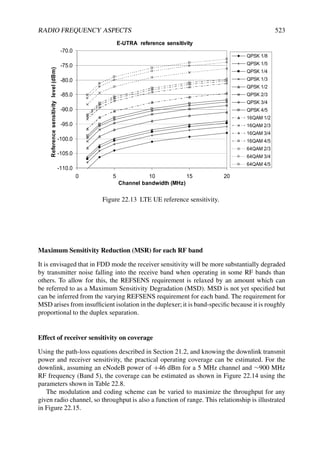
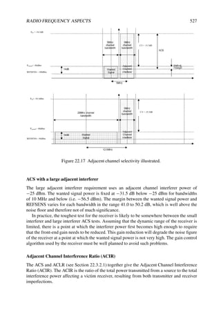
![2 LTE – THE UMTS LONG TERM EVOLUTION
auspices of the European Telecommunications Standards Institute (ETSI), GSM became a
robust, interoperable and widely-accepted standard.
Fuelled by advances in mobile handset technology, which resulted in small, fashionable
terminals with a long battery life, the widespread acceptance of the GSM standard exceeded
initial expectations and helped to create a vast new market. The resulting near-universal
penetration of GSM phones in the developed world provided an ease of communication
never previously possible, first by voice and text message, and later also by more advanced
data services. Meanwhile in the developing world, GSM technology had begun to connect
communities and individuals in remote regions where fixed-line connectivity was non-
existent and would be prohibitively expensive to deploy.
This ubiquitous availability of user-friendly mobile communications, together with
increasing consumer familiarity with such technology and practical reliance on it, thus
provides the context for new systems with more advanced capabilities. In the following
section, the series of progressions which have succeeded GSM is outlined, culminating in
the development of the system currently known as LTE – the Long Term Evolution of UMTS
(Universal Mobile Telecommunications System).
1.1.2 LTE in the Mobile Radio Landscape
In contrast to transmission technologies using media such as copper lines and optical
fibres, the radio spectrum is a medium shared between different, and potentially interfering,
technologies.
As a consequence, regulatory bodies – in particular, ITU-R (International Telecommuni-
cation Union, Radio Communication Sector) [1], but also regional and national regulators
– play a key role in the evolution of radio technologies since they decide which parts of
the spectrum and how much bandwidth may be used by particular types of service and
technology. This role is facilitated by the standardization of families of radio technologies
– a process which not only provides specified interfaces to ensure interoperability between
equipment from a multiplicity of vendors, but also aims to ensure that the allocated spectrum
is used as efficiently as possible, so as to provide an attractive user experience and innovative
services.
The complementary functions of the regulatory authorities and the standardization
organizations can be summarized broadly by the following relationship:
Aggregated data rate = bandwidth
regulation and licences
(ITU-R, regional regulators)
× spectral efficiency
technology
and standards
On a worldwide basis, ITU-R defines technology families and associates specific parts
of the spectrum with these families. Facilitated by ITU-R, spectrum for mobile radio
technologies is identified for the radio technologies which meet the ITU-R’s requirements
to be designated as members of the International Mobile Telecommunications (IMT) family.
Effectively, the IMT family comprises systems known as ‘Third Generation’ (for the first
time providing data rates up to 2 Mbps) and beyond.
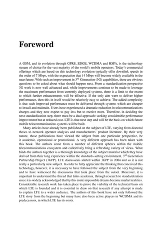
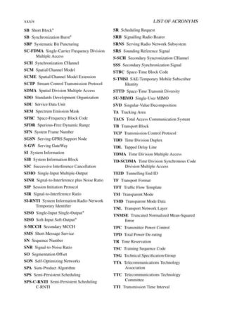
From the technology and standards angle, there are currently three main organizations
responsible for developing the standards meeting IMT requirements, and which are continu-
ing to shape the landscape of mobile radio systems, as shown in Figure 1.1.](https://image.slidesharecdn.com/ltefromtheorytopractise-240124145854-b0067765/85/LTE_from_Theory_to_Practise-pdf-33-320.jpg)


![INTRODUCTION AND BACKGROUND 7
1.2 Requirements and Targets for the Long Term
Evolution
Discussion of the key requirements for the new LTE system led to the creation of a formal
‘Study Item’ in 3GPP with the specific aim of ‘evolving’ the 3GPP radio access technology
to ensure competitiveness over a 10-year time-frame. Under the auspices of this Study Item,
the requirements for LTE were refined and crystallized, being finalized in June 2005.
They can be summarized as follows:
• reduced delays, in terms of both connection establishment and transmission latency;
• increased user data rates;
• increased cell-edge bit-rate, for uniformity of service provision;
• reduced cost per bit, implying improved spectral efficiency;
• greater flexibility of spectrum usage, in both new and pre-existing bands;
• simplified network architecture;
• seamless mobility, including between different radio-access technologies;
• reasonable power consumption for the mobile terminal.
It can also be noted that network operator requirements for next generation mobile systems
were formulated by the Next Generation Mobile Networks (NGMN) alliance of network
operators [2], which served as an additional reference for the development and assessment
of the LTE design. Such operator-driven requirements will also guide the development of the
next phase of LTE, namely LTE-Advanced (see Chapter 24).
To address these objectives, the LTE system design covers both the radio interface and
the radio network architecture. The main chapters of this book describe the technologies by
which these targets are achieved, and even exceeded in some aspects, by the first version of
the LTE system.
1.2.1 System Performance Requirements
Improved system performance compared to existing systems is one of the main requirements
from network operators, to ensure the competitiveness of LTE and hence to arouse market
interest. In this section, we highlight the main performance metrics used in the definition of
the LTE requirements and its performance assessment.
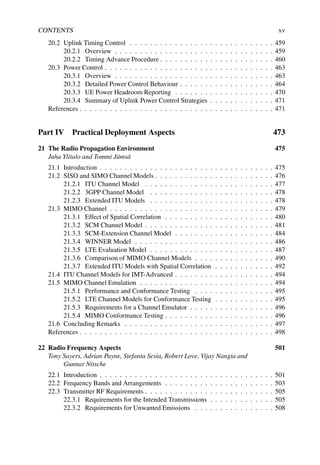
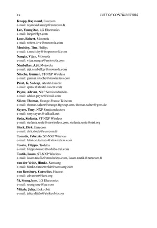
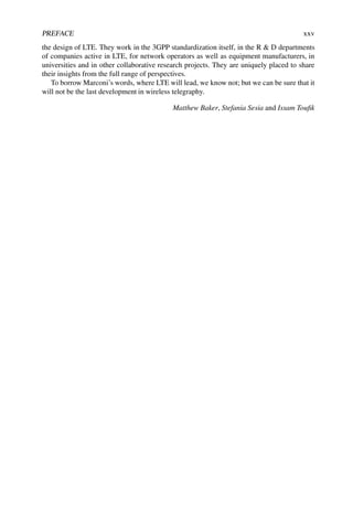
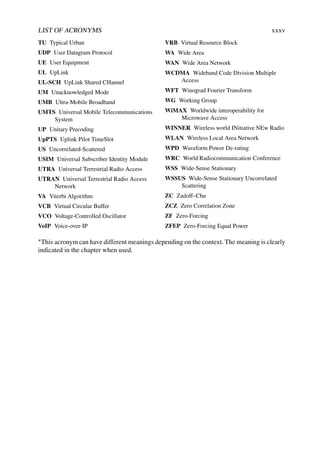
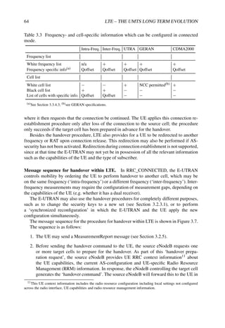
Table 1.1 summarizes the main performance requirements to which the first release of LTE
was designed. Many of the figures are given relative to the performance of the most advanced
available version of UMTS, which at the time of the definition of the LTE requirements
was HSDPA/HSUPA Release 6 – referred to here as the reference baseline. It can be seen
that the target requirements for LTE represent a significant step from the capacity and user
experience offered by the ‘Third Generation’ mobile communications systems which were
being deployed at the time when LTE was being developed.](https://image.slidesharecdn.com/ltefromtheorytopractise-240124145854-b0067765/85/LTE_from_Theory_to_Practise-pdf-38-320.jpg)
![8 LTE – THE UMTS LONG TERM EVOLUTION
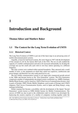
Table 1.1 Summary of key performance requirement targets for LTE.
Absolute
requirement
Comparison
to Release 6 Comment
Downlink
Peak transmission rate
100 Mbps 7 × 14.4 Mbps LTE in 20 MHz FDD,
2 × 2 spatial multiplexing.
Reference: HSDPA in 5 MHz
FDD, single antenna transmission
Peak spectral efficiency 5 bps/Hz 3 bps/Hz
Average cell spectral
efficiency
1.6 – 2.1
bps/Hz/cell
3 – 4 × 0.53
bps/Hz/cell
LTE: 2 × 2 spatial multiplexing,
Interference Rejection Combining
(IRC) receiver [3].
Reference: HSDPA, Rake
receiver [4], 2 receive antennas
Cell edge spectral
efficiency
0.04 – 0.06
bps/Hz/user
2-3 × 0.02
bps/Hz
As above,
10 users assumed per cell
Broadcast spectral
efficiency
1 bps/Hz N/A
Dedicated carrier for
broadcast mode
Uplink
Peak transmission rate
50 Mbps 5 × 11 Mbps LTE in 20 MHz FDD,
single antenna transmission.
Reference: HSUPA in 5 MHz
FDD, single antenna transmission
Peak spectral efficiency 2.5 bps/Hz 2 bps/Hz
Average cell spectral
efficiency
0.66 – 1.0
bps/Hz/cell
2 – 3 × 0.33
bps/Hz
LTE: single antenna transmission,
IRC receiver [3].
Reference: HSUPA, Rake
receiver [4], 2 receive antennas
Cell edge spectral
efficiency
0.02 – 0.03
bps/Hz/user
2 – 3 × 0.01
bps/Hz
As above,
10 users assumed per cell
System
User plane latency
(two way radio delay)
10 ms One fifth
Connection set-up
latency
100 ms Idle state active state
Operating bandwidth 1.4 – 20 MHz 5 MHz
(initial requirement started at 1.25
MHz)
VoIP capacity NGMN preferred target expressed in [2] is 60 sessions/MHz/cell
As mentioned above, HSPA technologies are also continuing to be developed to offer
higher spectral efficiencies than were assumed for the reference baseline case. However, LTE
has been able to benefit from avoiding the constraints of backward compatibility, enabling the
inclusion of advanced MIMO schemes in the system design from the beginning, and highly
flexible spectrum usage built around new multiple access schemes.
The requirements shown in Table 1.1 are discussed and explained in more detail below.
1.2.1.1 Peak Rates and Peak Spectral Efficiency
For marketing purposes, the first parameter by which different radio access technologies are
usually compared is the peak per-user data rate which can be achieved. This peak data rate
generally scales according to amount of spectrum used, and, for MIMO systems, according
to the minimum of the number of transmit and receive antennas (see Section 11.1).](https://image.slidesharecdn.com/ltefromtheorytopractise-240124145854-b0067765/85/LTE_from_Theory_to_Practise-pdf-39-320.jpg)
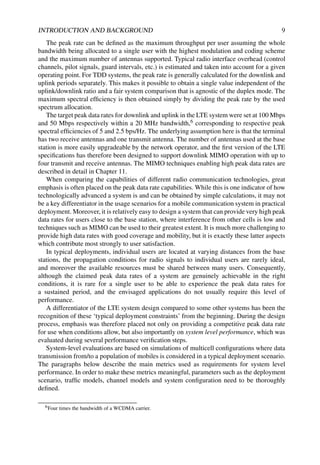
![10 LTE – THE UMTS LONG TERM EVOLUTION
The key definitions used for the system evaluations of LTE can be found in an operator
input document addressing the performance verification milestone in the LTE development
process [5]. This document takes into account deployment scenarios and channel models
agreed during the LTE Study Item [6], and is based on an evaluation methodology elaborated
by NGMN NGMN operators in [7]. The reference deployment scenarios which were given
special consideration for the LTE performance evaluation covered macrocells with base
station separations of between 500 m and 1.7 km, as well as microcells using MIMO with
base station separations of 130 m. A range of mobile terminal speeds were studied, focusing
particularly on the range 3–30 km/h, although higher mobile speeds were also considered
important.
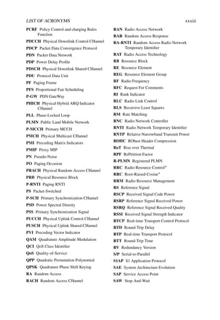
1.2.1.2 Cell Throughput and Spectral Efficiency
Performance at the cell level is an important criterion, as it relates directly to the number
of cell sites that a network operator requires, and hence to the capital cost of deploying the
system. For LTE, it was chosen to assess the cell level performance with full-queue traffic
models (i.e. assuming that there is never a shortage of data to transmit if a user is given the
opportunity) and a relatively high system load, typically 10 users per cell.
The requirements at the cell level were defined in terms of the following metrics:
• Average cell throughput [bps/cell] and spectral efficiency [bps/Hz/cell].
• Average user throughput [bps/user] and spectral efficiency [bps/Hz/user].
• Cell-edge user throughput [bps/user] and spectral efficiency [bps/Hz/user]. The metric
used for this assessment is the 5-percentile user throughput, obtained from the
cumulative distribution function of the user throughput.
For the UMTS Release 6 reference baseline, it was assumed that both the terminal and
the base station use a single transmit antenna and two receive antennas; for the terminal
receiver the assumed performance corresponds to a two-branch Rake receiver [4] with linear
combining of the signals from the two antennas.
For the LTE system, the use of two transmit and receive antennas was assumed at the base
station. At the terminal two receive antennas were assumed, but still only a single transmit
antenna. The receiver for both downlink and uplink is assumed to be a linear receiver with
optimum combining of the signals from the antenna branches [3]. In the uplink, higher per-
user throughput should be achievable by also using multiple transmit antennas at the terminal,
which will be considered for future releases of LTE.
The original requirements for the cell level metrics were only expressed as relative gains
compared to the Release 6 reference baseline. The absolute values provided in Table 1.1 are
based on evaluations of the reference system performance that can be found in [8] and [9] for
downlink and uplink respectively.
1.2.1.3 Voice Capacity
Unlike full queue traffic (such as file download) which is typically delay-tolerant and does
not require a guaranteed bit-rate, real-time traffic such as Voice over IP (VoIP) has tight delay
constraints. It is important to set system capacity requirements for such services – a particular
challenge in fully packet-based systems like LTE which rely on adaptive scheduling.](https://image.slidesharecdn.com/ltefromtheorytopractise-240124145854-b0067765/85/LTE_from_Theory_to_Practise-pdf-41-320.jpg)
![INTRODUCTION AND BACKGROUND 11
The system capacity requirement is defined as the number of satisfied VoIP users, given
a particular traffic model and delay constraints. The details of the traffic model used for
evaluating LTE can be found in [5]. Here, a VoIP user is considered to be in outage (i.e. not
satisfied) if more than 2% of the VoIP packets do not arrive successfully at the radio receiver
within 50 ms and are therefore discarded. This assumes an overall end-to-end delay (from
mobile terminal to mobile terminal) below 200 ms. The system capacity for VoIP can then be
defined as the number of users present per cell when more than 95% of the users are satisfied.
The NGMN group of network operators expressed a preference for the ability to support
60 satisfied VoIP sessions per MHz – an increase of two to four times what can typically
be achieved in the Release 6 reference case. This is an area where there is scope for further
enhancement of LTE in later releases.
1.2.1.4 Mobility and Cell Ranges
In terms of mobility, the LTE system is required to support communication with terminals
moving at speeds of up to 350 km/h, or even up to 500 km/h depending on the frequency
band. The primary scenario for operation at such high speeds is usage on high-speed trains
– a scenario which is increasing in importance across the world as the number of high-speed
rail lines increases and train operators aim to offer an attractive working environment to their
passengers. These requirements mean that handover between cells has to be possible without
interruption – in other words, with imperceptible delay and packet loss for voice calls, and
with reliable transmission for data services.
These targets are to be achieved by the LTE system in typical cells of radius up to 5 km,
while operation should continue to be possible for cell ranges of up to 100 km to enable
wide-area deployments.
1.2.1.5 Broadcast Mode Performance
Although not available in the first release due to higher prioritization of other service
modes, LTE is required to integrate an efficient broadcast mode for high rate Multimedia
Broadcast/Multicast Services (MBMS) such as Mobile TV, based on a Single Frequency
Network mode of operation as explained in detail in Chapter 14. This mode is able to operate
either on a shared carrier frequency together with unicast transmissions, or on a dedicated
broadcast carrier. To ensure efficient broadcast performance a requirement was defined for
the dedicated carrier case.
In broadcast systems, the system throughput is limited to what is achievable for the users
in the worst conditions. Consequently, the broadcast performance requirement was defined in
terms of an achievable system throughput (bps) and spectral efficiency (bps/Hz) assuming a
coverage of 98% of the nominal coverage area of the system. This means that only 2% of the
locations in the nominal coverage area are in outage – where outage for broadcast services is
defined as experiencing a packet error rate higher than 1%.
This broadcast spectral efficiency requirement was set to 1 bps/Hz [10].
1.2.1.6 User Plane Latency
User plane latency is an important performance metric for real-time and interactive services.
On the radio interface, the minimum user plane latency can be calculated based on signalling](https://image.slidesharecdn.com/ltefromtheorytopractise-240124145854-b0067765/85/LTE_from_Theory_to_Practise-pdf-42-320.jpg)

![INTRODUCTION AND BACKGROUND 13
1.2.2.1 Spectrum Allocations and Duplex Modes
As demand for suitable radio spectrum for mobile communications increases, LTE is required
to be able to operate in a wide range of frequency bands and sizes of spectrum allocations
in both uplink and downlink. LTE can use spectrum allocations ranging from 1.4 to 20 MHz
with a single carrier and addresses all frequency bands currently identified for IMT systems
by ITU-R [1] including those below 1 GHz.
This will in due course include deploying LTE in spectrum currently occupied by older
radio access technologies – a practice often known as ‘spectrum refarming’.
The ability to operate in both paired and unpaired spectrum is required, depending on
spectrum availability. LTE provides support for FDD, TDD and half-duplex FDD operation
in a unified design, ensuring a high degree of commonality which facilitates implementation
of multimode terminals and allows worldwide roaming.
1.2.2.2 Inter-Working with Other Radio Access Technologies
Flexible interoperation with other radio access technologies is essential for service continuity,
especially during the migration phase in early deployments of LTE with partial coverage,
where handover to legacy systems will often occur.
LTE relies on an evolved packet core network which allows interoperation with various
access technologies, in particular earlier 3GPP technologies (GSM/EDGE and UTRAN) as
well as non-3GPP technologies (e.g. WiFi, CDMA2000 and WiMAX).
However, service continuity and short interruption times can only be guaranteed if
measurements of the signals from other systems and fast handover mechanisms are integrated
in the LTE radio access design. In its first releases LTE will thus support tight inter-working
with all legacy 3GPP technologies and some non-3GPP technologies such as CDMA2000.
1.2.2.3 Terminal Complexity and Cost
A key consideration for competitive deployment of LTE is the availability of low-cost
terminals with long battery life, both in stand-by and during activity. Therefore, low terminal
complexity has been taken into account where relevant throughout the LTE system, as well
as designing the system wherever possible to support low terminal power consumption.
1.2.2.4 Network Architecture Requirements
LTE is required to allow a cost-effective deployment by an improved radio access network
architecture design including:
• flat architecture consisting of just one type of node, the base station, known in LTE as
the eNodeB;
• effective protocols for the support of packet-switched services;
• open interfaces and support of multivendor equipment interoperability;
• efficient mechanisms for operation and maintenance, including self-optimization
functionalities;](https://image.slidesharecdn.com/ltefromtheorytopractise-240124145854-b0067765/85/LTE_from_Theory_to_Practise-pdf-44-320.jpg)


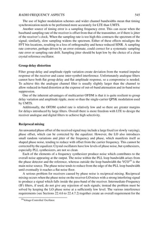
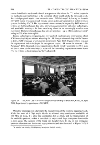
![20 LTE – THE UMTS LONG TERM EVOLUTION
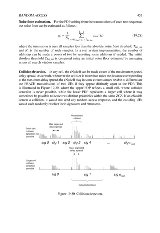
and operation, including the design of the associated procedures for random access, timing
control and power control which are essential to the efficient operation of the uplink.
This leads on to Part 4, which examines a number of aspects of the LTE system which
arise specifically as a result of it being a mobile cellular system. Chapter 21 provides a
thorough analysis of the characteristics of the radio propagation environments in which LTE
systems will be deployed, since an understanding of the propagation environment underpins
much of the technology adopted for the LTE specifications. The new technologies and
bandwidths adopted in LTE also have implications for the radio-frequency implementation
of the mobile terminals in particular, and some of these are analysed in Chapter 22. The
LTE system is designed to operate not just in wide bandwidths but also in a diverse range of
spectrum allocation scenarios, and Chapter 23 therefore addresses the different duplex modes
applicable to LTE and the effects that these may have on system design and operation.
Finally, Part 5 recognizes that the initial version of the LTE system will not terminate
the long process of advancement of mobile communications. Chapter 24 takes us beyond
the initial version of LTE to consider some of the ways in which the evolution is already
continuing towards LTE-Advanced, in response to the latest challenges posed by the ITU-R
and by the ever-higher expectations of end-users.
References13
[1] ITU, ‘International Telecommunications Union’, www.itu.int/itu-r.
[2] NGMN, ‘Next Generation Mobile Networks Beyond HSPA EVDO – A white paper’,
www.ngmn.org, December 2006.
[3] J. H. Winters, Optimum Combining in Digital Mobile Radio with Cochannel Interference. IEEE
Journal on Selected Areas in Communications, Vol. 2, July 1984.
[4] R. Price and P. E. Green, ‘A Communication Technique for Multipath Channels’ in Proceedings
of the IRE, Vol. 46, March 1958.
[5] Orange, China Mobile, KPN, NTT DoCoMo, Sprint, T-Mobile, Vodafone, and Telecom Italia,
‘R1-070674: LTE Physical Layer Framework for Performance Verification’, www.3gpp.org,
3GPP TSG RAN WG1, meeting 48, St Louis, USA, February 2007.
[6] 3GPP Technical Report 25.814, ‘Physical Layer Aspects for Evolved UTRA (Release 7)’,
www.3gpp.org.
[7] NGMN, ‘Next Generation Mobile Networks Radio Access Performance Evaluation Methodol-
ogy’, www.ngmn.org, June 2007.
[8] Ericsson, ‘R1-072578: Summary of Downlink Performance Evaluation’, www.3gpp.org, 3GPP
TSG RAN WG1, meeting 49, Kobe, Japan, May 2007.
[9] Nokia, ‘R1-072261: LTE Performance Evaluation – Uplink Summary’, www.3gpp.org, 3GPP
TSG RAN WG1, meeting 49, Kobe, Japan, May 2007.
[10] 3GPP Technical Report 25.913, ‘Requirements for Evolved UTRA (E-UTRA) and Evolved
UTRAN (E-UTRAN) (Release 7)’, www.3gpp.org.
13All web sites confirmed 18th December 2008.](https://image.slidesharecdn.com/ltefromtheorytopractise-240124145854-b0067765/85/LTE_from_Theory_to_Practise-pdf-51-320.jpg)


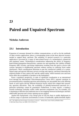
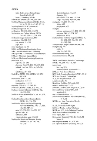
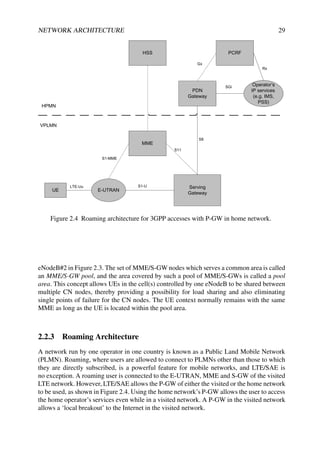
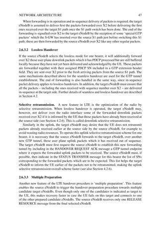
![NETWORK ARCHITECTURE 25
Internet
Figure 2.2 Functional split between E-UTRAN and EPC. Reproduced by permission of
© 3GPP.
In addition to these nodes, EPC also includes other logical nodes and functions such as
the Home Subscriber Server (HSS) and the Policy Control and Charging Rules Function
(PCRF). Since the EPS only provides a bearer path of a certain QoS, control of multimedia
applications such as VoIP is provided by the IP Multimedia Subsystem (IMS) which is
considered to be outside the EPS itself.
The logical CN nodes (specified in [1]) are shown in Figure 2.1 and discussed in more
detail in the following.
• PCRF. It is responsible for policy control decision-making, as well as for controlling
the flow-based charging functionalities in the Policy Control Enforcement Function
(PCEF) which resides in the P-GW. The PCRF provides the QoS authorization (QoS
class identifier and bitrates) that decides how a certain data flow will be treated in the
PCEF and ensures that this is in accordance with the user’s subscription profile.
• Home Location Register (HLR). The HLR contains users’ SAE subscription data
such as the EPS-subscribed QoS profile and any access restrictions for roaming (see
Section 2.2.3). It also holds information about the PDNs to which the user can connect.
This could be in the form of an Access Point Name (APN) (which is a label according
to DNS1 naming conventions describing the access point to the PDN), or a PDN
Address (indicating subscribed IP address(es)). In addition the HLR holds dynamic
information such as the identity of the MME to which the user is currently attached
1Domain Name System.](https://image.slidesharecdn.com/ltefromtheorytopractise-240124145854-b0067765/85/LTE_from_Theory_to_Practise-pdf-55-320.jpg)
![26 LTE – THE UMTS LONG TERM EVOLUTION
or registered. The HLR may also integrate the Authentication Centre (AuC) which
generates the vectors for authentication and security keys.
• P-GW. The P-GW is responsible for IP address allocation for the UE, as well as QoS
enforcement and flow-based charging according to rules from the PCRF. The P-GW is
responsible for the filtering of downlink user IP packets into the different QoS based
bearers. This is performed based on Traffic Flow Templates (TFTs) (see Section 2.4).
The P-GW performs QoS enforcement for Guaranteed Bit Rate (GBR) bearers. It also
serves as the mobility anchor for inter-working with non-3GPP technologies such
as CDMA2000 and WiMAX networks (see Section 2.2.4 and Chapter 13 for more
information about mobility).
• S-GW. All user IP packets are transferred through the S-GW, which serves as the local
mobility anchor for the data bearers when the UE moves between eNodeBs. It also
retains the information about the bearers when the UE is in idle state (known as ECM-
IDLE, see Section 2.2.1.1) and temporarily buffers downlink data while the MME
initiates paging of the UE to re-establish the bearers. In addition, the S-GW performs
some administrative functions in the visited network such as collecting information
for charging (e.g. the volume of data sent to or received from the user), and legal
interception. It also serves as the mobility anchor for inter-working with other 3GPP
technologies such as GPRS and UMTS (see Section 2.2.4 and Chapter 13 for more
information about mobility).
• MME. The MME is the control node which processes the signalling between the UE
and the CN. The protocols running between the UE and the CN are known as the
Non-Access Stratum (NAS) protocols.
The main functions supported by the MME are classified as:
Functions related to bearer management. This includes the establishment, mainte-
nance and release of the bearers, and is handled by the session management layer in
the NAS protocol.
Functions related to connection management. This includes the establishment of the
connection and security between the network and UE, and is handled by the connection
or mobility management layer in the NAS protocol layer.
NAS control procedures are specified in [1] and are discussed in more detail in the
following section.
2.2.1.1 Non-Access Stratum (NAS) Procedures
The NAS procedures, especially the connection management procedures, are fundamentally
similar to UMTS. The main change from UMTS is that EPS allows concatenation of some
procedures to allow faster establishment of the connection and the bearers.
The MME creates a UE context when a UE is turned on and attaches to the network. It
assigns a unique short temporary identity termed the SAE-Temporary Mobile Subscriber
Identity (S-TMSI) to the UE which identifies the UE context in the MME. This UE
context holds user subscription information downloaded from the HSS. The local storage
of subscription data in the MME allows faster execution of procedures such as bearer](https://image.slidesharecdn.com/ltefromtheorytopractise-240124145854-b0067765/85/LTE_from_Theory_to_Practise-pdf-56-320.jpg)
![NETWORK ARCHITECTURE 27
establishment since it removes the need to consult the HSS every time. In addition, the UE
context also holds dynamic information such as the list of bearers that are established and the
terminal capabilities.
To reduce the overhead in the E-UTRAN and processing in the UE, all UE-related
information in the access network can be released during long periods of data inactivity.
This state is called EPS Connection Management IDLE (ECM-IDLE). The MME retains the
UE context and the information about the established bearers during these idle periods.
To allow the network to contact an ECM-IDLE UE, the UE updates the network as to
its new location whenever it moves out of its current Tracking Area (TA); this procedure
is called a ‘Tracking Area Update’. The MME is responsible for keeping track of the user
location while the UE is in ECM-IDLE.
When there is a need to deliver downlink data to an ECM-IDLE UE, the MME sends a
paging message to all the eNodeBs in its current TA, and the eNodeBs page the UE over the
radio interface. On receipt of a paging message, the UE performs a service request procedure
which results in moving the UE to ECM-CONNECTED state. UE-related information is
thereby created in the E-UTRAN, and the bearers are re-established. The MME is responsible
for the re-establishment of the radio bearers and updating the UE context in the eNodeB. This
transition between the UE states is called an idle-to-active transition. To speed up the idle-to-
active transition and bearer establishment, EPS supports concatenation of the NAS and AS
procedures for bearer activation (see also Section 2.4.1). Some inter-relationship between
the NAS and AS protocols is intentionally used to allow procedures to run simultaneously
rather than sequentially, as in UMTS. For example, the bearer establishment procedure can
be executed by the network without waiting for the completion of the security procedure.
Security functions are the responsibility of the MME for both signalling and user data.
When a UE attaches with the network, a mutual authentication of the UE and the network is
performed between the UE and the MME/HSS. This authentication function also establishes
the security keys which are used for encryption of the bearers, as explained in Section 3.2.3.1.
The security architecture for SAE is specified in [2].
2.2.2 The Access Network
The Access Network of LTE, E-UTRAN, simply consists of a network of eNodeBs, as
illustrated in Figure 2.3. For normal user traffic (as opposed to broadcast), there is no
centralized controller in E-UTRAN; hence the E-UTRAN architecture is said to be flat.
The eNodeBs are normally inter-connected with each other by means of an interface
known as X2, and to the EPC by means of the S1 interface – more specifically, to the MME
by means of the S1-MME interface and to the S-GW by means of the S1-U interface.
The protocols which run between the eNodeBs and the UE are known as the Access
Stratum (AS) protocols.
The E-UTRAN is responsible for all radio-related functions, which can be summarized
briefly as:
• Radio Resource Management. This covers all functions related to the radio bearers,
such as radio bearer control, radio admission control, radio mobility control, schedul-
ing and dynamic allocation of resources to UEs in both uplink and downlink (see
Chapter 13).](https://image.slidesharecdn.com/ltefromtheorytopractise-240124145854-b0067765/85/LTE_from_Theory_to_Practise-pdf-57-320.jpg)

![30 LTE – THE UMTS LONG TERM EVOLUTION
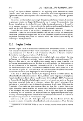
Figure 2.5 Architecture for 3G UMTS interworking.
2.2.4 Inter-Working with other Networks
EPS also supports inter-working and mobility (handover) with networks using other Radio
Access Technologies (RATs), notably GSM, UMTS, CDMA2000 and WiMAX. The archi-
tecture for inter-working with 2G and 3G GPRS/UMTS networks is shown in Figure 2.5.
The S-GW acts as the mobility anchor for inter-working with other 3GPP technologies
such as GSM and UMTS, while the P-GW serves as an anchor allowing seamless mobility
to non-3GPP networks such as CDMA2000 or WiMAX. The P-GW may also support a
Proxy Mobile Internet Protocol (PMIP) based interface. More details of the radio interface
procedures for inter-working are specified in [3] and are also covered in Sections 2.5.6.2 and
3.2.4.
2.3 Protocol Architecture
We outline here the radio protocol architecture of E-UTRAN.
2.3.1 User Plane
An IP packet for a UE is encapsulated in an EPC-specific protocol and tunnelled between the
P-GW and the eNodeB for transmission to the UE. Different tunnelling protocols are used
across different interfaces. A 3GPP-specific tunnelling protocol called the GPRS Tunnelling
Protocol (GTP) [4] is used over the core network interfaces, S1 and S5/S8.2
The E-UTRAN user plane protocol stack is shown greyed in Figure 2.6, consisting
of the PDCP (Packet Data Convergence Protocol), RLC (Radio Link Control) and MAC
2SAE also provides an option to use PMIP on S5/S8. More details on the MIP-based S5/S8 interface can be
found in [3].](https://image.slidesharecdn.com/ltefromtheorytopractise-240124145854-b0067765/85/LTE_from_Theory_to_Practise-pdf-60-320.jpg)

![32 LTE – THE UMTS LONG TERM EVOLUTION
The greyed region of the stack indicates the access stratum protocols. The lower layers
perform the same functions as for the user plane with the exception that there is no header
compression function for control plane.
The RRC protocol is known as ‘Layer 3’ in the access stratum protocol stack. It is the
main controlling function in the access stratum, being responsible for establishing the radio
bearers and configuring all the lower layers using RRC signalling between the eNodeB and
the UE. These functions are detailed in Section 3.2.
2.4 Quality of Service and EPS Bearers
In a typical case, multiple applications may be running in a UE at any time, each one having
different QoS requirements. For example, a UE can be engaged in a VoIP call while at
the same time browsing a web page or downloading an FTP file. VoIP has more stringent
requirements for QoS in terms of delay and delay jitter than web browsing and FTP, while the
latter requires a much lower packet loss rate. In order to support multiple QoS requirements,
different bearers are set up within EPS, each being associated with a QoS.
Broadly, bearers can be classified into two categories based on the nature of the QoS they
provide:
• Minimum Guaranteed Bit Rate (GBR) bearers which can be used for applications
such as VoIP. These have an associated GBR value for which dedicated transmission
resources are permanently allocated (e.g. by an admission control function in the
eNodeB) at bearer establishment/modification. Bit rates higher than the GBR may be
allowed for a GBR bearer if resources are available. In such cases, a Maximum Bit
Rate (MBR) parameter, which can also be associated with a GBR bearer, sets an upper
limit on the bit rate which can be expected from a GBR bearer.
• Non-GBR bearers which do not guarantee any particular bit rate. These can be used
for applications such as web browsing or FTP transfer. For these bearers, no bandwidth
resources are allocated permanently to the bearer.
In the access network, it is the responsibility of the eNodeB to ensure the necessary QoS
for a bearer over the radio interface. Each bearer has an associated QoS Class Identifier (QCI),
and an Allocation and Retention Priority (ARP).
Each QCI is characterized by priority, packet delay budget and acceptable packet loss
rate. The QCI label for a bearer determines how it is handled in the eNodeB. Only a dozen
such QCIs have been standardized so that vendors can all have the same understanding
of the underlying service characteristics and thus provide the corresponding treatment,
including queue management, conditioning and policing strategy. This ensures that an LTE
operator can expect uniform traffic handling behaviour throughout the network regardless
of the manufacturers of the eNodeB equipment. The set of standardized QCIs and their
characteristics (from which the PCRF in an EPS can select) is provided in Table 2.1
(from Section 6.1.7, in [5]). The QCI table specifies values for the priority handling,
acceptable delay budget and packet error loss rate for each QCI label.
The priority and packet delay budget (and to some extent the acceptable packet loss rate)
from the QCI label determine the RLC mode configuration (see Section 4.3.1), and how the
scheduler in the MAC (Section 4.4.2.1) handles packets sent over the bearer (e.g. in terms of](https://image.slidesharecdn.com/ltefromtheorytopractise-240124145854-b0067765/85/LTE_from_Theory_to_Practise-pdf-62-320.jpg)
![NETWORK ARCHITECTURE 33
Table 2.1 Standardized QoS Class Identifiers (QCIs) for LTE.
Resource Packet delay Packet error
QCI type Priority budget (ms) loss rate Example services
1 GBR 2 100 10−2 Conversational voice
2 GBR 4 150 10−3 Conversational video (live
streaming)
3 GBR 5 300 10−6 Non-conversational video
(buffered streaming)
4 GBR 3 50 10−3 Real time gaming
5 Non-GBR 1 100 10−6 IMS signalling
6 Non-GBR 7 100 10−3 Voice, video (live streaming),
interactive gaming
7 Non-GBR 6 300 10−6 Video (buffered streaming)
8 Non-GBR 8 300 10−6 TCP-based (e.g. WWW, e-mail)
chat, FTP, p2p file sharing,
progressive video, etc.
9 Non-GBR 9 300 10−6
scheduling policy, queue management policy and rate shaping policy). For example, a packet
with a higher priority can be expected to be scheduled before a packet with lower priority. For
bearers with a low acceptable loss rate, an Acknowledged Mode (AM) can be used within the
RLC protocol layer to ensure that packets are delivered successfully across the radio interface
(see Section 4.3.1.3).
The ARP of a bearer is used for call admission control – i.e. to decide whether or
not the requested bearer should be established in case of radio congestion. It also governs
the prioritization of the bearer for pre-emption with respect to a new bearer establishment
request. Once successfully established, a bearer’s ARP does not have any impact on the
bearer-level packet forwarding treatment (e.g. for scheduling and rate control). Such packet
forwarding treatment should be solely determined by the other bearer level QoS parameters
such as QCI, GBR and MBR.
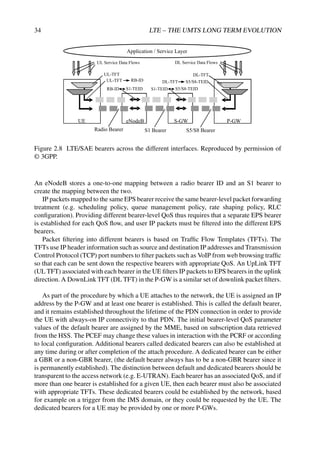
An EPS bearer has to cross multiple interfaces as shown in Figure 2.8 – the S5/S8 interface
from the P-GW to the S-GW, the S1 interface from the S-GW to the eNodeB, and the radio
interface (also known as the LTE-Uu interface) from the eNodeB to the UE. Across each
interface, the EPS bearer is mapped onto a lower layer bearer, each with its own bearer
identity. Each node must keep track of the binding between the bearer IDs across its different
interfaces.
An S5/S8 bearer transports the packets of an EPS bearer between a P-GW and a S-GW.
The S-GW stores a one-to-one mapping between an S1 bearer and an S5/S8 bearer. The
bearer is identified by the GTP tunnel ID across both interfaces.
An S1 bearer transports the packets of an EPS bearer between a S-GW and an eNodeB.
A radio bearer [6] transports the packets of an EPS bearer between a UE and an eNodeB.](https://image.slidesharecdn.com/ltefromtheorytopractise-240124145854-b0067765/85/LTE_from_Theory_to_Practise-pdf-63-320.jpg)

![NETWORK ARCHITECTURE 37
SCTP
IP
Data link layer
S1-AP
Physical layer
Radio
network
layer
Transport
network
layer
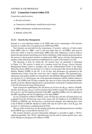
Figure 2.10 S1-MME control plane protocol stack. Reproduced by permission of © 3GPP.
The SCTP protocol is well known for its advanced features inherited from TCP which
ensure the required reliable delivery of the signalling messages. In addition it makes it
possible to benefit from improved features such as the handling of multistreams to implement
transport network redundancy easily and avoid head-of-line blocking or multihoming (see
‘IETF RFC4960’ [7]).
A further simplification in LTE (compared to the UMTS Iu interface, for example) is
the direct mapping of S1-AP (S1 Application Protocol) on top of SCTP. This results in a
simplified protocol stack compared to UMTS with no intermediate connection management
protocol. The individual connections are directly handled at the application layer. Multiplex-
ing takes place between S1-AP and SCTP whereby each stream of an SCTP association is
multiplexed with the signalling traffic of multiple individual connections.
One further area of flexibility brought with LTE lies in the lower layer protocols for which
full optionality has been left regarding the choice of the IP version and the choice of the data
link layer. For example, this enables the operator to start deployment using IP version 4 with
the data link tailored to the network deployment scenario.
2.5.1.2 User Plane
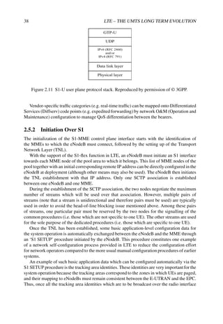
Figure 2.11 gives the protocol structure of the S1 user plane, which is based on the
GTP/UDP5/IP stack which is already well known from UMTS networks.
One of the advantages of using GTP-User plane (GTP-U) is its inherent facility to identify
tunnels and also to facilitate intra-3GPP mobility.
The IP version number and the data link layer have been left fully optional, as for the
control plane stack.
A transport bearer is identified by the GTP tunnel endpoints and the IP address (source
Tunnelling End ID (TEID), destination TEID, source IP address, destination IP address).
The S-GW sends downlink packets of a given bearer to the eNodeB IP address (received in
S1-AP) associated to that particular bearer. Similarly, the eNodeB sends upstream packets of
a given bearer to the EPC IP address (received in S1-AP) associated to that particular bearer.
5User Datagram Protocol.](https://image.slidesharecdn.com/ltefromtheorytopractise-240124145854-b0067765/85/LTE_from_Theory_to_Practise-pdf-67-320.jpg)


![50 LTE – THE UMTS LONG TERM EVOLUTION
References6
[1] 3GPP Technical Specification 24.301, ‘Non-Access-Stratum (NAS) protocol for Evolved Packet
System (EPS); Stage 3 (Release 8)’, www.3gpp.org.
[2] 3GPP Technical Specification 33.401, ‘System Architecture Evolution (SAE): Security
Architecture (Release 8)’, www.3gpp.org.
[3] 3GPP Technical Specification 23.402, ‘Architecture enhancements for non-3GPP accesses
(Release 8)’, www.3gpp.org.
[4] 3GPP Technical Specification 29.060, ‘General Packet Radio Service (GPRS); GPRS Tunnelling
Protocol (GTP) across the Gn and Gp interface (Release 8)’, www.3gpp.org.
[5] 3GPP Technical Specification 23.203, ‘Policy and charging control architecture (Release 8)’,
www.3gpp.org.
[6] 3GPP Technical Specification 36.300, ‘Evolved Universal Terrestrial Radio Access (E-UTRA)
and Evolved Universal Terrestrial Radio Access Network (E-UTRAN); Overall description; Stage
2 (Release 8)’, www.3gpp.org.
[7] Request for Comments 4960 The Internet Engineering Task Force (IETF), Network
Working Group, ‘Stream Control Transmission Protocol’, http://www.ietf.org.
6All web sites confirmed 18th December 2008.](https://image.slidesharecdn.com/ltefromtheorytopractise-240124145854-b0067765/85/LTE_from_Theory_to_Practise-pdf-80-320.jpg)

![52 LTE – THE UMTS LONG TERM EVOLUTION
of the shared transmission resources in time and frequency. The UE provides the network
with reports of its buffer status and of the downlink channel quality, as well as neighbouring
cell measurement information to enable E-UTRAN to select the most appropriate cell for
the UE. These measurement reports include cells using other frequencies or RATs. The
UE also receives system information, consisting mainly of information required to use the
transmission channels. To extend its battery lifetime, a UE in RRC_CONNECTED may be
configured with a Discontinuous Reception (DRX) cycle.
RRC, as specified in [1], is the protocol by which the E-UTRAN controls the UE
behaviour in RRC_CONNECTED. RRC also specifies the control signalling applicable for a
UE in RRC_IDLE, namely paging and system information. The UE behaviour in RRC_IDLE
is specified in [2].
Chapter 13 gives some further details of the UE measurements which support the mobility
procedures.
Functionality related to Multimedia Broadcast/Multicast Services (MBMSs) is covered
separately in Chapter 14.
3.2 Radio Resource Control (RRC)
3.2.1 Introduction
The RRC protocol supports the transfer of common NAS information (i.e. NAS information
which is applicable to all UEs) as well as dedicated NAS information (which is applicable
only to a specific UE). In addition, for UEs in RRC_IDLE, RRC supports notification of
incoming calls.
The RRC protocol covers a number of functional areas.
• System information handles the broadcasting of system information, which includes
NAS common information. Some of the system information is applicable only for
UEs in RRC_IDLE while other system information is also applicable for UEs in
RRC_CONNECTED.
• RRC connection control covers all procedures related to the establishment, modifi-
cation and release of an RRC connection, including paging, initial security activation,
establishment of Signalling Radio Bearers (SRBs) and of radio bearers carrying user
data (Data Radio Bearers, DRBs), handover within LTE (including transfer of UE RRC
context information4), configuration of the lower protocol layers,5 access class barring
and radio link failure.
• Network controlled inter-RAT mobility includes (besides the mobility procedures)
security activation and transfer of UE RRC context information.
• Measurement configuration and reporting for intra-frequency, inter-frequency and
inter-RAT mobility, includes configuration and activation of measurement gaps.
4This UE context information includes the radio resource configuration including local settings not configured
across the radio interface, UE capabilities and radio resource management information.
5Packet Data Convergence Protocol (PDCP), Radio Link Control (RLC), Medium Access Control (MAC), all of
which are explained in detail in Chapter 4, and the physical layer which is explained in Chapters 5–11 and 15–20.](https://image.slidesharecdn.com/ltefromtheorytopractise-240124145854-b0067765/85/LTE_from_Theory_to_Practise-pdf-82-320.jpg)


![60 LTE – THE UMTS LONG TERM EVOLUTION
Step 1: Connection establishment
• Upper layers in the UE trigger connection establishment, which may be in response
to paging. The UE checks if access is barred (see Section 3.3.4.6). If this is not the
case, the lower layers in the UE perform a contention-based random access procedure
as described in Section 19.3, and the UE starts a timer (known as T300) and sends the
RRCConnectionRequest message. This message includes an initial identity (S-TMSI9
or a random number) and an establishment cause.
• If E-UTRAN accepts the connection, it returns the RRCConnectionSetup message
that includes the initial radio resource configuration including SRB1. Instead of
signalling each individual parameter, E-UTRAN may order the UE to apply a default
configuration – i.e. a configuration for which the parameter values are specified in the
RRC specification [1].
• The UE returns the RRCConnectionSetupComplete message and includes the NAS
message, an identifier of the selected PLMN (used to support network sharing) and,
if provided by upper layers, an identifier of the registered MME. Based on the last
two parameters, the eNodeB decides on the CN node to which it should establish the
S1-connection.
Step 2: Initial security activation and radio bearer establishment
• E-UTRAN sends the SecurityModeCommand message to activate integrity protection
and ciphering. This message, which is integrity-protected but not ciphered, indicates
which algorithms shall be used.
• The UE verifies the integrity protection of the SecurityModeControl message, and, if
this succeeds, it configures lower layers to apply integrity protection and ciphering
to all subsequent messages (with the exception that ciphering is not applied to the
response message, i.e. the SecurityModeComplete (or SecurityModeFailure) mes-
sage).
• E-UTRAN sends the RRCConnectionReconfiguration message including a radio
resource configuration used to establish SRB2 and one or more DRBs. This message
may also include other information such as a piggybacked NAS message or a
measurement configuration. E-UTRAN may send the RRCConnectionReconfiguration
message prior to receiving the SecurityModeComplete message. In this case, E-
UTRAN should release the connection when one (or both) procedures fail (because
the two procedures result from a single S1-procedure, which does not support partial
success).
• The UE finally returns the RRCConnectionReconfigurationComplete message.
A connection establishment may fail for a number of reasons, such as the following:
• Access may be barred (see Section 3.3.4.6).
9S-Temporary Mobile Subscriber Identity.](https://image.slidesharecdn.com/ltefromtheorytopractise-240124145854-b0067765/85/LTE_from_Theory_to_Practise-pdf-90-320.jpg)


![74 LTE – THE UMTS LONG TERM EVOLUTION
3.3.4.1 Measurement Rules
To enable the UE to save battery power, rules have been defined which limit the measure-
ments the UE is required to perform. Firstly, the UE is required to perform intra-frequency
measurements only when the quality of the serving cell is below or equal to a threshold
(‘SintraSearch’). Furthermore, the UE is required to measure other frequencies/RATs of
lower or equal priority only when the quality of the serving cell is below or equal to another
threshold (‘SnonintraSearch’). The UE is always required to measure frequencies and RATs
of higher priority. The required performance (i.e. how often the UE is expected to make the
measurements, and to what extent this depends on, for example, the serving cell quality) is
specified in [3].
3.3.4.2 Frequency/RAT Evaluation
E-UTRAN configures an absolute priority for all applicable frequencies of each RAT. In
addition to the cell-specific priorities which are optionally provided via system information,
E-UTRAN can assign UE-specific priorities via dedicated signalling. Of the frequencies that
are indicated in the system information, the UE is expected to consider for cell reselection
only those for which it has priorities. Equal priorities are not applicable for inter-RAT cell
reselection.
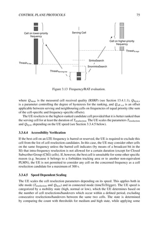
The UE reselects to a cell on a higher priority frequency if the S-criterion (see
Section 3.3.3) of the concerned target cell exceeds a high threshold (ThreshX-High) for longer
than a certain duration Treselection. The UE reselects to a cell on a lower-priority frequency
if the S-criterion of the serving cell is below a low threshold (ThreshServing-Low) while
the S-criterion of the target cell on a lower-priority frequency (possibly on another RAT)
exceeds a low threshold (ThreshX-Low) during the time interval Treselection, while no cell on
a higher-priority frequency is available. Figure 3.13 illustrates the condition(s) to be met for
reselecting to a cell on a higher-priority frequency (light grey bar) and to a cell on a lower
priority frequency (dark grey bars).
When reselecting to a frequency, possibly on another RAT, which has a different priority,
the UE reselects to the highest-ranked cell on the frequency concerned (see Section 3.3.4.3).
Note that, as indicated in Section 3.2.3.4, thresholds and priorities are configured per
frequency, while Treselection is configured per RAT.
From Release-8 onwards, UMTS and GERAN support the same priority-based cell
reselection as provided in LTE, with a priority per frequency.Release-8 radio access networks
will continue to handle legacy UEs by means of offset-based ranking. Likewise, Release-8
UEs should apply the ranking based on radio link quality (with offsets) unless UMTS or
GERAN indicate support for priority-based reselection.
3.3.4.3 Cell Ranking
The UE ranks the intra-frequency cells and the cells on other frequencies having equal
priority which fulfil the S-criterion using a criterion known as the R-criterion. The R-criterion
generates rankings Rs and Rn for the serving cell and neighbour cells respectively:
For the serving cell: Rs = Qmeas,s + Qhyst,s
For neighbour cells: Rn = Qmeas,n + Qoff s,n](https://image.slidesharecdn.com/ltefromtheorytopractise-240124145854-b0067765/85/LTE_from_Theory_to_Practise-pdf-104-320.jpg)
![76 LTE – THE UMTS LONG TERM EVOLUTION
hysteresis. For idle and connected modes, separate sets of control parameters are used,
signalled in SIB3 and within the measurement configuration respectively.
3.3.4.6 Cell Access Restrictions
Access barring is performed during connection establishment (see Section 3.2.3.2) and
provides a means to control the load introduced by UE-originated traffic. There are separate
means for controlling Mobile Originated (MO) calls and MO signalling.
Each UE belongs to an Access Class (AC) in the range 0–9. In addition, some UEs
may belong to one or more high-priority ACs in the range 11–15, which are reserved for
specific uses (e.g. security services, public utilities, emergency services, PLMN staff). AC10
is used for emergency access. Further details, for example regarding in which PLMN the
high priority ACs apply, are provided in [4]. The UE considers access to be barred if access
is barred for all its applicable ACs.
SIB2 may include a set of AC barring parameters for MO calls and/or MO signalling.
This set of parameters comprises a probability factor and a barring timer for AC0–9 and a
list of barring bits for AC11–15. For AC0–9, if the UE initiates a MO call and the relevant
AC barring parameters are included, the UE draws a random number. If this number exceeds
the probability factor, access is not barred. Otherwise access is barred for a duration which
is randomly selected centred on the broadcast barring timer value. For AC11–15, if the UE
initiates a MO call and the relevant AC barring parameters are included, access is barred
whenever the bit corresponding to all of the UE’s ACs is set. The behaviour is similar in the
case of UE-initiated MO signalling.
For cell (re)selection, the UE is expected to consider cells which are neither barred nor
reserved for operator or future use. In addition, a UE with an access class in the range 11–15
shall consider a cell that is (only) reserved for operator use and part of its home PLMN (or
an equivalent) as a candidate for cell reselection. The UE is not even allowed to perform
emergency access on a cell which is not considered to be a candidate for cell reselection.
3.3.4.7 Any Cell Selection
When the UE is unable to find a suitable cell of the selected PLMN, it performs ‘any cell
selection’. In this case, the UE performs normal idle mode operation: monitoring paging,
acquiring system information, performing cell reselection. In addition, the UE regularly
attempts to find a suitable cell on other frequencies or RATs (i.e. not listed in system
information). The UE is not allowed to receive MBMS in this state.
3.3.4.8 Closed Subscriber Group
LTE supports the existence of cells which are accessible only for a limited set of UEs – a
Closed Subscriber Group (CSG). In order to prevent UEs from attempting to register on a
CSG cell on which they do not have access, the UE maintains a CSG white list, i.e. a list
of CSG identities for which access has been granted to the UE. The CSG white list can be
transferred to the UE by upper layers, or updated upon successful access of a CSG cell. To
facilitate the latter, UEs support ‘manual selection’ of CSG cells which are not in the CSG
white list. The manual selection may be requested by the upper layers, based on a text string
broadcast by the cell.](https://image.slidesharecdn.com/ltefromtheorytopractise-240124145854-b0067765/85/LTE_from_Theory_to_Practise-pdf-106-320.jpg)

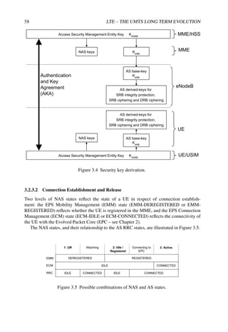
![78 LTE – THE UMTS LONG TERM EVOLUTION
two subframes within the paging frame. The LTE specifications include a table that indicates
the subframe applicable for each combination of Ns and i_s, which is the index that follows
from Equation (3.1). Figure 3.14 illustrates cases B and C. The non-blank subframes are used
for paging, while the grey ones are applicable for the UE with the indicated identity.
Radio frame with
SFN=76
Case C
Case B
Radio frame with
SFN=204
Radio frame with
SFN=2
Radio frame with
SFN=130
Figure 3.14 Paging frame and paging occasion examples.
3.5 Summary
The main aspects of the Control Plane protocols in LTE can be broken down into the Cell
Selection and Reselection Procedures when the UE is in Idle Mode, and the RRC protocol
when the UE is in Connected Mode.
The roles of these protocols include supporting security, mobility both between different
LTE cells and between LTE and other radio systems, and establishment and reconfiguration
of the radio bearers which carry control information and user data.
References14
[1] 3GPP Technical Specification 36.331, ‘Evolved Universal Terrestrial Radio Access (E-UTRA);
Radio Resource Control (RRC); Protocol specification (Release 8)’, www.3gpp.org.
[2] 3GPP Technical Specification 36.304, ‘Evolved Universal Terrestrial Radio Access (E-UTRA);
User Equipment (UE) procedures in idle mode (Release 8)’, www.3gpp.org.
[3] 3GPP Technical Specification 36.133, ‘Evolved Universal Terrestrial Radio Access (E-UTRA);
Requirements for support of radio resource management (Release 8)’, www.3gpp.org.
[4] 3GPP Technical Specification 22.011, ‘Service accessibility (Release 8)’, www.3gpp.org.
14All web sites confirmed 18th December 2008.](https://image.slidesharecdn.com/ltefromtheorytopractise-240124145854-b0067765/85/LTE_from_Theory_to_Practise-pdf-108-320.jpg)
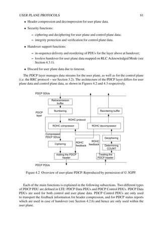
![4
User Plane Protocols
Patrick Fischer, SeungJune Yi, SungDuck Chun and
YoungDae Lee
4.1 Introduction to the User Plane Protocol Stack
The LTE Layer 2 user-plane protocol stack is composed of three sublayers, as shown in
Figure 4.1:
• The Packet Data Convergence Protocol (PDCP) layer [1]: This layer processes
Radio Resource Control (RRC) messages in the control plane and Internet Protocol
(IP) packets in the user plane. Depending on the radio bearer, the main functions of the
PDCP layer are header compression, security (integrity protection and ciphering), and
support for reordering and retransmission during handover. There is one PDCP entity
per radio bearer.
• The Radio Link Control (RLC) layer [2]: The main functions of the RLC layer are
segmentation and reassembly of upper layer packets in order to adapt them to the size
which can actually be transmitted over the radio interface. For radio bearers which
need error-free transmission, the RLC layer also performs retransmission to recover
from packet losses. Additionally, the RLC layer performs reordering to compensate for
out-of-order reception due to Hybrid Automatic Repeat reQuest (HARQ) operation in
the layer below. There is one RLC entity per radio bearer.
• The Medium Access Control (MAC) layer [3]: This layer performs multiplexing of
data from different radio bearers. Therefore there is only one MAC entity per UE.
By deciding the amount of data that can be transmitted from each radio bearer and
instructing the RLC layer as to the size of packets to provide, the MAC layer aims
to achieve the negotiated Quality of Service (QoS) for each radio bearer. For the
LTE – The UMTS Long Term Evolution: From Theory to Practice Stefania Sesia, Issam Toufik and Matthew Baker
© 2009 John Wiley Sons, Ltd. ISBN: 978-0-470-69716-0](https://image.slidesharecdn.com/ltefromtheorytopractise-240124145854-b0067765/85/LTE_from_Theory_to_Practise-pdf-109-320.jpg)


![110 LTE – THE UMTS LONG TERM EVOLUTION
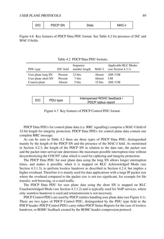
4.5 Summary of the User Plane Protocols
The LTE Layer 2 protocol stack, consisting of the PDCP, RLC and MAC sublayers, acts as
the interface between the radio access technology-agnostic sources of packet data traffic and
the LTE physical layer. By providing functionality such as IP packet header compression,
security, handover support, segmentation/concatenation, retransmission and reordering of
packets, and transmission scheduling, the protocol stack enables the physical layer to be
used efficiently for packet data traffic.
References16
[1] 3GPP Technical Specification 36.323, ‘Packet Data Convergence Protocol (PDCP) Specification
(Release 8)’, www.3gpp.org.
[2] 3GPP Technical Specification 36.322, ‘Radio Link Control (RLC) Protocol Specification
(Release 8)’, www.3gpp.org.
[3] 3GPP Technical Specification 36.321, ‘Medium Access Control (MAC) Protocol Specification
(Release 8)’, www.3gpp.org.
16All web sites confirmed 18th December 2008.](https://image.slidesharecdn.com/ltefromtheorytopractise-240124145854-b0067765/85/LTE_from_Theory_to_Practise-pdf-140-320.jpg)

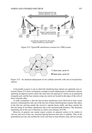
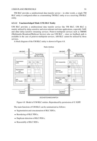
![114 LTE – THE UMTS LONG TERM EVOLUTION
Saving in spectrum
(a)
(b)
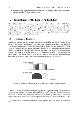
Figure 5.1 Spectral efficiency of OFDM compared to classical multicarrier modulation:
(a) classical multicarrier system spectrum; (b) OFDM system spectrum.
and Hybrid Automatic Repeat reQuest (HARQ) to overcome the deep fading which may be
encountered on the individual subchannels. These aspects are considered in Chapter 10 and
lead to the LTE downlink falling under the category of system often referred to as ‘Coded
OFDM’ (COFDM).
5.1.1 History of OFDM Development
Multicarrier communication systems were first introduced in the 1960s [1, 2], with the first
OFDM patent being filed at Bell Labs in 1966. Initially only analogue design was proposed,
using banks of sinusoidal signal generators and demodulators to process the signal for the
multiple subchannels. In 1971, the Discrete Fourier Transform (DFT) was proposed [3],
which made OFDM implementation cost-effective. Further complexity reductions were
realized in 1980 by the application of the Winograd Fourier Transform (WFT) or the Fast
Fourier Transform (FFT) [4].
OFDM then became the modulation of choice for many applications for both wired
systems (such as Asymmetric Digital Subscriber Line (ADSL)) and wireless systems.
Wireless applications of OFDM tended to focus on broadcast systems, such as Digital
Video Broadcasting (DVB) and Digital Audio Broadcasting (DAB), and relatively low-power
systems such as Wireless Local Area Networks (WLANs). Such applications benefit from the
low complexity of the OFDM receiver, while not requiring a high-power transmitter in the
consumer terminals. This avoids one of the main disadvantages of OFDM, namely that the
transmitters in high-power applications tend to be more expensive because of the high Peak
to Average Power Ratio (PAPR); this aspect is discussed in Section 5.2.2.
The first cellular mobile radio system based on OFDM was proposed in [5]. Since then, the
processing power of modern digital signal processors has increased remarkably, paving the
way for OFDM, after much research and development, to find its way into the LTE downlink.
Here, the key benefits of OFDM which come to the fore are not only the low-complexity
receiver but also the ability of OFDM to be adapted in a straightforward manner to operate
in different channel bandwidths according to spectrum availability.](https://image.slidesharecdn.com/ltefromtheorytopractise-240124145854-b0067765/85/LTE_from_Theory_to_Practise-pdf-143-320.jpg)
![116 LTE – THE UMTS LONG TERM EVOLUTION
IFFT
S/P
P/S DAC
Sk[0]
Sk[1]
Sk[N-2]
Sk[N-1]
xk[0]
xk[1]
xk[N-G]
xk[N-G]
xk[N-1]
xk[N-1]
Cyclic Prefix
Xk[0]
Xk[1]
Xk[N-2]
Xk[N-1]
FFT
ADC S/P
Yk[0]
Yk[1]
Yk[N-2]
Yk[N-1]
Cyclic Prefix removal
OFDM Transmitter
OFDM Receiver
]
0
[
CP
k
r
]
1
[
G
rCP
k
]
0
[
]
[ k
CP
k r
G
r
]
1
[
]
1
[ k
CP
k r
G
r
]
2
[
]
2
[
N
r
G
N
r k
CP
k
]
1
[
]
1
[
N
r
G
N
r k
CP
k
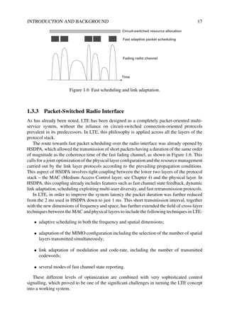
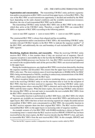
Figure 5.4 OFDM system model: (a) transmitter; (b) receiver.
This operation has the important advantage of requiring a much less complex equalization
procedure in the receiver, under the assumption that the time-varying channel impulse
response remains substantially constant during the transmission of each modulated OFDM
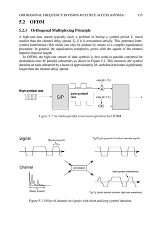
symbol. Figure 5.3 shows how the resulting long symbol duration is virtually unaffected by
ISI compared to the short symbol duration, which is highly corrupted.
Figure 5.4 shows the typical block diagram of an OFDM system. The signal to be
transmitted is defined in the frequency domain. A Serial to Parallel (S/P) converter collects
serial data symbols into a data block Sk = [Sk [0] , Sk [1] , . . . , Sk [M − 1]]T
of dimension
M, where the subscript k is the index of an OFDM symbol (spanning the M sub-carriers).
The M parallel data streams are first independently modulated resulting in the complex
vector Xk = [Xk [0] , Xk [1] , . . . , Xk [M − 1]]T
. Note that in principle it is possible to](https://image.slidesharecdn.com/ltefromtheorytopractise-240124145854-b0067765/85/LTE_from_Theory_to_Practise-pdf-145-320.jpg)
![ORTHOGONAL FREQUENCY DIVISION MULTIPLE ACCESS (OFDMA) 117
Tu
TCP Tu
TCP Tu
TCP
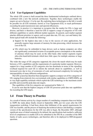
Figure 5.5 OFDM cyclic prefix insertion.
use different modulations (e.g. QPSK or 16QAM) on each sub-carrier; due to channel
frequency selectivity, the channel gain may differ between sub-carriers, and thus some
sub-carriers can carry higher data-rates than others. The vector of data symbols Xk then
passes through an Inverse FFT (IFFT) resulting in a set of N complex time-domain samples
xk = [xk[0], . . . , xk[N − 1]]T . In a practical OFDM system, the number of processed sub-
carriers is greater than the number of modulated sub-carriers (i.e. N ≥ M), with the un-
modulated sub-carriers being padded with zeros.
The next key operation in the generation of an OFDM signal is the creation of a guard
period at the beginning of each OFDM symbol, to eliminate the remaining impact of ISI
caused by multipath propagation. The guard period is obtained by adding a Cyclic Prefix
(CP) at the beginning of the symbol xk. The CP is generated by duplicating the last G
samples of the IFFT output and appending them at the beginning of xk. This yields the time
domain OFDM symbol [xk[N − G], . . . , xk[N − 1], xk[0], . . . , xk[N − 1]]T , as shown in
Figure 5.5.
To avoid ISI completely, the CP length G must be chosen to be longer than the longest
channel impulse response to be supported. The CP converts the linear (i.e. aperiodic)
convolution of the channel into a circular (i.e. periodic) one which is suitable for DFT
processing. This important feature of CP used in OFDM is explained more formally later
in this section.
The output of the IFFT is then Parallel-to-Serial (P/S) converted for transmission through
the frequency-selective channel.
At the receiver, the reverse operations are performed to demodulate the OFDM signal.
Assuming that time- and frequency-synchronization is achieved, a number of samples
corresponding to the length of the CP are removed, such that only an ISI-free block of
samples is passed to the DFT. If the number of subcarriers N is designed to be a power
of 2, a highly efficient FFT implementation may be used to transform the signal back to the
frequency domain. Among the N parallel streams output from the FFT, the modulated subset
of M subcarriers are selected and further processed by the receiver.
Let x(t) be the signal symbol transmitted at time instant t. The received signal in a
multipath environment is then given by
r(t) = x(t) ∗ h(t) + z(t) (5.1)
where h(t) is the continuous-time impulse response of the channel, ∗ represents the
convolution operation and z(t) is the additive noise. Assuming that x(t) is band-limited to
[− 1
2Ts
, 1
2Ts
], the continuous-time signal x(t) can be sampled at sampling rate Ts such that the
Nyquist criterion is satisfied.](https://image.slidesharecdn.com/ltefromtheorytopractise-240124145854-b0067765/85/LTE_from_Theory_to_Practise-pdf-146-320.jpg)
![118 LTE – THE UMTS LONG TERM EVOLUTION
As a result of the multipath propagation, several replicas of the transmitted signals arrive
at the receiver at different delays.
The received discrete-time OFDM symbol k including CP, under the assumption that the
channel impulse response has a length smaller than or equal to G, can be expressed as
rCP
=
rCP
k [0]
rCP
k [1]
.
.
.
rCP
k [G − 2]
rCP
k [G − 1]
rCP
k [G]
.
.
.
rk[N + G − 1]
= A ·
h[0]
h[1]
.
.
.
h[G − 1]
+
zk[0]
zk[1]
.
.
.
zk[G − 2]
zk[G − 1]
zk[G]
.
.
.
zk[N + G − 1]
(5.2)
where
A =
xk[N − G] xk−1[N − 1] xk−1[N − 2] · · · xk−1[N − G + 1]
xk[N − G + 1] xk[N − G] xk−1[N − 1] · · · xk−1[N − G + 2]
.
.
.
.
.
.
...
...
.
.
.
xk[N − 2] xk[N − 3]
... xk[N − G] xk−1[N − 1]
xk[N − 1] xk[N − 2]
... xk[N − G + 1] xk[N − G]
xk[0] xk[N − 1]
... xk[N − G + 2] xk[N − G + 1]
.
.
. · · · · · · · · ·
.
.
.
xk[N − 1] xk[N − 2] · · · · · · xk[N − G]
In general broadband transmission systems, one of the most complex operations the
receiver has to handle is the equalization process to recover xk[n] (from Equation (5.2)).
Equation (5.2) can be written as the sum of intra-OFDM symbol interference (generated
by the frequency-selective behaviour of the channel within an OFDM symbol) and the inter-
OFDM symbol interference (between two consecutive OFDM block transmissions at time k
and time (k − 1)). This can be expressed as
rCP
= AIntra ·
h[0]
h[1]
.
.
.
h[G − 1]
+ AInter ·
h[0]
h[1]
.
.
.
h[G − 1]
+
zk[0]
zk[1]
.
.
.
zk[N + G − 1]
zk[N − G]
.
.
.
zk[N + G − 1]
(5.3)](https://image.slidesharecdn.com/ltefromtheorytopractise-240124145854-b0067765/85/LTE_from_Theory_to_Practise-pdf-147-320.jpg)
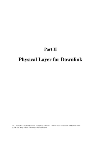
![ORTHOGONAL FREQUENCY DIVISION MULTIPLE ACCESS (OFDMA) 119
where
AIntra =
xk[N − G] 0 · · · 0
xk[N − G + 1] xk[N − G] · · · 0
.
.
.
...
...
.
.
.
xk[N − 1] · · ·
... xk[N − G]
xk[0] xk[N − 1] · · · xk[N − G + 1]
.
.
.
...
...
.
.
.
xk[N − 1] xk[N − 2] · · · xk[N − G]
and
AInter =
0 xk−1[N − 1] xk−1[N − 2] · · · xk−1[N − G + 1]
0 0 xk−1[N − 1] · · · xk−1[N − G + 2]
.
.
.
...
...
...
.
.
.
0 0 · · · 0 xk−1[N − 1]
0 0 · · · · · · 0
.
.
.
...
...
...
.
.
.
0 0 · · · · · · 0
In order to suppress the inter-OFDM symbol interference, the first G samples of the
received signal are discarded, leading to
rk[0]
rk[1]
.
.
.
rk[N − 1]
=
rCP
k [G]
rCP
k [G + 1]
.
.
.
rCP
k [N + G − 1]
=
xk[0] xk[N − 1] · · · xk[N − G + 1]
xk[1] xk[0] · · · xk[N − G + 2]
.
.
.
...
...
.
.
.
xk[N − 1] xk[N − 2] · · · xk[N − G]
·
h[0]
h[1]
.
.
.
h[G − 1]
+
zk[G]
zk[G + 1]
.
.
.
zk[N + G − 1]
](https://image.slidesharecdn.com/ltefromtheorytopractise-240124145854-b0067765/85/LTE_from_Theory_to_Practise-pdf-148-320.jpg)
![120 LTE – THE UMTS LONG TERM EVOLUTION
Adding zeros to the channel vector can extend the signal matrix without changing the
output vector. This can be expressed as
rk[0]
rk[1]
.
.
.
rk[N − 1]
= B ·
h[0]
h[1]
.
.
.
h[G − 1]
0
.
.
.
0
+
zk[G]
zk[G + 1]
.
.
.
zk[N + G − 1]
where matrix B is given by
B =
xk[0] xk[N − 1] · · · xk[N − G + 1] xk[N − G] · · · xk[1]
xk[1] xk[0] · · · xk[N − G + 2] xk[N − G + 1] · · · xk[2]
.
.
.
...
...
...
...
...
.
.
.
xk[N − 1] xk[N − 2] · · · xk[N − G] xk[N − G − 1] · · · xk[0]
The matrix B is circulant and thus it is diagonal in the Fourier domain with diagonal
elements given by the FFT of its first row [6,7]. It can then be written as B = FH XF, with X
diagonal, and the equivalent received signal can be expressed as follows:
rk[0]
rk[N − G + 1]
.
.
.
rk[N − 1]
= FH
·
Xk[0] 0 · · · 0
0 Xk[1] · · · 0
.
.
. · · ·
...
.
.
.
0 0 · · · Xk[N − 1]
· F ·
h[0]
h[1]
.
.
.
h[G − 1]
0
.
.
.
0
+
zk[N − G]
zk[N − G + 1]
.
.
.
zk[N + G − 1]
where F is the Fourier transform matrix whose elements are
(F)n,m =
1
√
N
exp −
j2π
N
(nm)
for 0 ≤ n ≤ N − 1 and 0 ≤ m ≤ N − 1 and N is the length of the OFDM symbol. The
elements on the diagonal are the eigenvalues of the matrix B, obtained as
Xk[m] =
1
√
N
N
n=1
xk[n] exp −2jπm
n
N
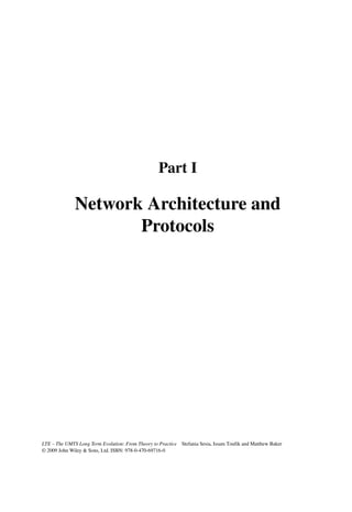
(5.4)](https://image.slidesharecdn.com/ltefromtheorytopractise-240124145854-b0067765/85/LTE_from_Theory_to_Practise-pdf-149-320.jpg)
![ORTHOGONAL FREQUENCY DIVISION MULTIPLE ACCESS (OFDMA) 121
In reverse, the time-domain signal xk[n] can be obtained by
xk[n] =
1
√
N
N
m=1
Xk[m] exp 2jπm
n
N
(5.5)
By applying the Fourier transform, the equivalent received signal in the frequency domain
can be obtained,
Rk[0]
.
.
.
Rk[N − 1]
=
Xk[0] 0 · · · 0
0 Xk[1] · · · 0
.
.
.
...
...
.
.
.
0 0 · · · Xk[N − 1]
H[0]
H[1]
.
.
.
H[N − 1]
+
Zk[0]
.
.
.
Zk[N − 1]
In summary, the CP of OFDM changes the linear convolution into a circular one. The
circular convolution is very efficiently transformed by means of an FFT into a multiplicative
operation in the frequency domain. Hence, the transmitted signal over a frequency-selective
(i.e. multipath) channel is converted into a transmission over N parallel flat-fading channels
in the frequency domain:
Rk[m] = Xk[m] · H[m] + Zk[m] (5.6)
As a result the equalization is much simpler than for single-carrier systems and consists of
just one complex multiplication per subcarrier.
5.2.2 Peak-to-Average Power Ratio and Sensitivity to Nonlinearity
In the previous section, the advantages of OFDM have been shown. By contrast, this section
highlights some of the main disadvantages of OFDM. One of the major drawbacks is that the
OFDM signal has a high Peak-to-Average Power Ratio (PAPR).
In the general case, the OFDM transmitter can be seen as a linear transform performed
over a large block of independently identically distributed (i.i.d) QAM-modulated complex
symbols (in the frequency domain). From the central limit theorem [8, 9], the time-domain
OFDM symbol may be approximated as a Gaussian waveform. The amplitude variations of
the OFDM modulated signal can therefore be very high. However, practical Power Amplifiers
(PAs) of RF transmitters are linear only within a limited dynamic range. Thus, the OFDM
signal is likely to suffer from non-linear distortion caused by clipping. This gives rise to out-
of-band spurious emissions and in-band corruption of the signal. To avoid such distortion, the
PAs have to operate with large power back-offs, leading to inefficient amplification and/or
expensive transmitters.
The PAPR is one measure of the high dynamic range of the input amplitude (and hence
a measure of the expected degradation). To analyse the PAPR mathematically, let x[n] be
the signal after IFFT as given by Equation (5.5) where the time index k can be dropped
without loss of generality. The PAPR of an OFDM symbol is defined as the square of the
peak amplitude divided by the mean power, i.e.
PAPR =
maxn{|x[n]|2}
E{|x[n]|2}
(5.7)
Under the hypothesis that the Gaussian approximation is valid, the amplitude of x[n] has a
Rayleigh distribution, while the power has a central chi-square distribution with two degrees](https://image.slidesharecdn.com/ltefromtheorytopractise-240124145854-b0067765/85/LTE_from_Theory_to_Practise-pdf-150-320.jpg)
![122 LTE – THE UMTS LONG TERM EVOLUTION
of freedom. The Cumulative Distribution Function (CDF) Fx(α) of the normalized power is
given by
Fx(α) = Pr
|x[n]|2
E{|x[n]|2}
α
= 1 − e−α
(5.8)
If there is no oversampling, the time-domain samples are mutually uncorrelated and the
probability that the PAPR1 is above a certain threshold PAPR0 is given by
Pr(PAPR PAPR0) = 1 − F(PAPR0)N
= 1 − (1 − e−PAPR0 )N
(5.9)
Figure 5.6 plots the distribution of the PAPR given by Equation (5.9) for different values of
the number of subcarriers N. The figure shows that a high PAPR does not occur very often.
However, when it does occur, degradation due to PA non-linearities may be expected.
2 4 6 8 10 12 14
10
6
10
5
10
4
10
3
10
2
10
1
10
0
PAPR0
Pr
{PAPR
PAPR
0
}
N=16
N=32
N=128
N=2048
N=512
Figure 5.6 PAPR distribution for different numbers of OFDM subcarriers.
In order to evaluate the impacts of distortion on the OFDM signal reception, in Chapter 22
a useful framework for modelling non-linearities is developed.
5.2.2.1 PAPR Reduction Techniques
Many techniques have been studied for reducing the PAPR of a transmitted OFDM signal.
Although no such techniques are specified for the LTE downlink signal generation, an
overview of the possibilities is provided below. In general in LTE the cost and complexity
1Note that the CDF of the PAPR is FPAPR(η) = [Fx(η)]N for N i.i.d. samples.](https://image.slidesharecdn.com/ltefromtheorytopractise-240124145854-b0067765/85/LTE_from_Theory_to_Practise-pdf-151-320.jpg)
![ORTHOGONAL FREQUENCY DIVISION MULTIPLE ACCESS (OFDMA) 123
of generating the OFDM signal with acceptable Error Vector Magnitude (EVM) is left to the
eNodeB implementation. As OFDM is not used for the LTE uplink (see Section 15.2), such
considerations do not directly apply to the transmitter in the UE.
Techniques for PAPR reduction of OFDM signals can be broadly categorized into three
main concepts:
• Clipping and filtering [10–12]. The time-domain signal is clipped to a predefined
level. This causes spectral leakage into adjacent channels, resulting in reduced spectral
efficiency as well as in-band noise degrading the bit error rate performance. Out-of-
band radiation caused by the clipping process can, however, be reduced by filtering.
If discrete signals are clipped directly, the resulting clipping noise will all fall in band
and thus cannot be reduced by filtering. To avoid this problem, one solution consists of
oversampling the original signal by padding the input signal with zeros and processing
it using a longer IFFT. The oversampled signal is clipped and then filtered to reduce
the out-of-band radiation.
• Selected mapping [13]. Multiple transmit signals which represent the same OFDM
data symbol are generated by multiplying the OFDM symbol by different phase
vectors. The representation with the lowest PAPR is selected. To recover the phase
information, it is of course necessary to use separate control signalling to indicate to
the receiver which phase vector was used.
• Coding techniques [14,15]. These techniques consist of finding the code words with
the lowest PAPR from a set of codewords to map the input data. A look-up table may
be used if N is small. It is shown that complementary codes have good properties to
combine both PAPR and forward error correction.
The latter two concepts are not applicable in the context of LTE; selected mapping
would require additional signalling, while techniques based on codeword selection are not
compatible with the data scrambling used in the LTE downlink.
5.2.3 Sensitivity to Carrier Frequency Offset and Time-Varying
Channels
The orthogonality of OFDM relies on the condition that transmitter and receiver operate with
exactly the same frequency reference. If this is not the case, the perfect orthogonality of the
subcarriers is lost, causing subcarrier leakage, also known as Inter-Carrier Interference (ICI),
as can be seen in Figure 5.7.
Frequency errors typically arise from a mismatch between the reference frequencies of
the transmitter and the receiver local oscillators. On the receiver side in particular, due to the
importance of using low-cost components in the mobile handset, local oscillator frequency
drifts are usually greater than in the eNodeB and are typically a function of parameters such as
temperature changes and voltage variation. This difference between the reference frequencies
is widely referred to as Carrier Frequency Offset (CFO). Phase noise in the UE receiver may
also result in frequency errors.
The CFO can be several times larger than the subcarrier spacing. It is usually divided into
an integer part and a fractional part. Thus the frequency error can be written as
fo = ( + )f (5.10)](https://image.slidesharecdn.com/ltefromtheorytopractise-240124145854-b0067765/85/LTE_from_Theory_to_Practise-pdf-152-320.jpg)
![124 LTE – THE UMTS LONG TERM EVOLUTION
0
Frequency
Amplitude
fo
Figure 5.7 Loss of orthogonality between OFDM subcarriers due to frequency offset.
where f is the subcarrier spacing, is an integer and −0.5 0.5. If = 0, then the
modulated data are in the wrong positions with respect to the subcarrier mapping performed
at the transmitter. This simply results in a Bit Error Rate (BER) of 0.5 if the frequency offset
is not compensated at the receiver independently of the value of . In the case of = 0 and
= 0, the perfect subcarrier orthogonality is lost, resulting in ICI which can degrade the
BER. Typically only synchronization errors of up to a few percent of the subcarrier spacing
are tolerable in OFDM systems.
Even in an ideal case where the local oscillators are perfectly aligned, the relative speed
between transmitter and receiver also generates a frequency error due to Doppler.
In the case of a single-path channel, UE mobility in a constant direction with respect
to the angle of arrival of the signal results in a Doppler shift fd, while in a scattering
environment this becomes a Doppler spread with spectral density P(f ) as discussed further
in Section 8.3.1.
It can be shown [16, 17] that, for both flat and dispersive channels, the ICI power can be
computed as a function of the generic Doppler spectral density P(f ) as follows:
PICI =
fdmax
−fdmax
P(f )(1 − sinc2
(Tsf )) df (5.11)
where fdmax is the maximum Doppler frequency, and the transmitted signal power is
normalized.
ICI resulting from a mismatch fo between the transmitter and receiver oscillator frequen-
cies can be modelled as a Doppler shift arising from single-path propagation:
P(f ) = δ(f − fo) (5.12)
Hence, substituting (5.12) into (5.11), the ICI power in the case of a deterministic CFO is
given by
PICI,CFO = 1 − sinc2
(foTs) (5.13)](https://image.slidesharecdn.com/ltefromtheorytopractise-240124145854-b0067765/85/LTE_from_Theory_to_Practise-pdf-153-320.jpg)
![ORTHOGONAL FREQUENCY DIVISION MULTIPLE ACCESS (OFDMA) 125
For the classical Jakes model of Doppler spread (see Section 8.3.1), the expression (5.11)
can be written as
PICI,Jakes = 1 − 2
1
0
(1 − f )J0(2πfdmax Tsf ) df (5.14)
where J0 is the zero-th order Bessel function.
When no assumptions on the shape of the Doppler spectrum can be made, an upper
bound on the ICI given by Equation (5.11) can be found by applying the Cauchy–Schwartz
inequality, leading to [17]
PICI ≤
1
0 [1 − sinc2
(fdTsf )]2 df
1
0 1 − sinc2
(fdTsf ) df
(5.15)
This upper bound on PICI is valid only in the case of frequency spread and does not cover
the case of a deterministic CFO.
Using Equations (5.15), (5.14) and (5.13), the SIR in the presence of ICI can be expressed
as
SIRICI =
1 − PICI
PICI
(5.16)
Figures 5.8 and 5.9 plot these PICI and SIRICI for the cases provided. These figures
show that the highest ICI is introduced by a constant frequency offset. In the case of a
Doppler spread, the ICI impairment is lower. Figure 5.9 shows that, in the absence of any
other impairment such as interference (SIR = ∞), the SIRICI rapidly decays as a function of
frequency misalignments.
The sensitivity of the BER depends on the modulation order. It is shown in reference [18]
that QPSK modulation can tolerate up to max = 0.05 whereas 64-QAM requires ≤ 0.01.
5.2.4 Timing Offset and Cyclic Prefix Dimensioning
In the case of a memoryless channel (i.e. no delay spread), OFDM is insensitive to timing
synchronization errors provided that the misalignment remains within the cyclic prefix
duration. In other words, if To ≤ TCP (with To being the timing error), then orthogonality
is maintained thanks to the cyclic nature of the CP. Any symbol timing delay only introduces
a constant phase shift from one subcarrier to another. The received signal at the mth subcarrier
is given by
Rk[m] = Xk[m] exp
j2π
dm
N
(5.17)
where d is the timing offset in samples corresponding to a duration equal to To.
This phase shift can be recovered as part of the channel estimation operation. It is worth
highlighting that the insensitivity to timing offsets would not hold for any kind of guard
period other than a cyclic prefix; for example, zero-padding would not exhibit the same
property, resulting in a portion of the useful signal power being lost.
In the general case of a channel with delay spread, for a given CP length the maximum
tolerated timing offset without degrading the OFDM reception is reduced by an amount equal
to the length of the channel impulse response: To ≤ TCP − Td as shown in Figure 5.10. For
greater timing errors, ISI and ICI occur. The effect caused by an insufficient CP is discussed](https://image.slidesharecdn.com/ltefromtheorytopractise-240124145854-b0067765/85/LTE_from_Theory_to_Practise-pdf-154-320.jpg)

![ORTHOGONAL FREQUENCY DIVISION MULTIPLE ACCESS (OFDMA) 127
ISI from next OFDM Symbol
No ISI
ISI from previous OFDM Symbol
Channel
length
Figure 5.10 OFDM sensitivity to timing offsets.
in the following section. Timing synchronization hence becomes more critical in long-delay-
spread channels.
Initial timing acquisition in LTE is normally achieved by the cell-search and synchro-
nization procedures (see Chapter 7). Thereafter, for continuous tracking of the timing-offset,
two classes of approach exist, based on either CP correlation or Reference Signals (RSs). A
combination of the two is also possible. The reader is referred to [19] for a comprehensive
survey on OFDM synchronization techniques.
5.2.4.1 Effect of Insufficient Cyclic Prefix Length
As already introduced before, if an OFDM system is designed with a CP of length G samples
such that L G where L is the length of the channel impulse response (in number of
samples), the system benefits from turning the linear convolution into a circular one to keep
the subcarriers orthogonal. The condition of a sufficient CP is therefore strictly related to the
orthogonality property of OFDM.
As shown in [20], for an OFDM symbol consisting of N + G samples where N is the FFT
size, the power of the ICI and ISI can be computed by
PICI = 2
N+G−1
k=G
|h[k]|2 N(k − G) − (k − G)2
N2
(5.18)
PISI =
N+G−1
k=G
|h[k]|2 (k − G)2
N2
(5.19)
Conversely, the signal power PS is reduced and can be written as
PS =
G−1
k=0
|h(k)|2
+
N+G−1
k=G
|h(k)|2 (N − k + G)2
N2
(5.20)
The resulting SIR due to the CP being too short can then be written as
SIRog =
PS
PISI + PICI
(5.21)
Figures 5.11 and 5.12 plot Equations (5.19) to (5.21) for the case of the normal CP length
in LTE assuming a channel with a uniform and normalized power-delay profile of length
L N + G, where the dashed line marks the boundary of the cyclic prefix (L = G).](https://image.slidesharecdn.com/ltefromtheorytopractise-240124145854-b0067765/85/LTE_from_Theory_to_Practise-pdf-156-320.jpg)
![128 LTE – THE UMTS LONG TERM EVOLUTION
B)
P
ISI
(dB
boundary of the
cyclic prefix
L/(N+G)
Figure 5.11 Power of signal, ICI and ISI in case of a too-short guard interval.
5.3 OFDMA
Orthogonal Frequency Division Multiple Access (OFDMA) is an extension of OFDM to the
implementation of a multiuser communication system. In the discussion above, it has been
assumed that a single user receives data on all the subcarriers at any given time. OFDMA
distributes subcarriers to different users at the same time, so that multiple users can be
scheduled to receive data simultaneously. Usually, subcarriers are allocated in contiguous
groups for simplicity and to reduce the overhead of indicating which subcarriers have been
allocated to each user.
OFDMA for mobile communications was first proposed in [21] based on multicarrier
FDMA (Frequency Division Multiple Access), where each user is assigned to a set of
randomly selected subchannels.
OFDMA enables the OFDM transmission to benefit from multiuser diversity, as discussed
in Chapter 12. Based on feedback information about the frequency-selective channel
conditions from each user, adaptive user-to-subcarrier assignment can be performed, enhanc-
ing considerably the total system spectral efficiency compared to single-user OFDM systems.
OFDMA can also be used in combination with Time Division Multiple Access (TDMA),
such that the resources are partitioned in the time-frequency plane – i.e. groups of subcarriers
for a specific time duration. In LTE, such time-frequency blocks are known as Resource
Blocks (RBs), as explained in Section 6.2. Figure 5.13 depicts such an OFDMA/TDMA
mixed strategy as used in LTE.](https://image.slidesharecdn.com/ltefromtheorytopractise-240124145854-b0067765/85/LTE_from_Theory_to_Practise-pdf-157-320.jpg)
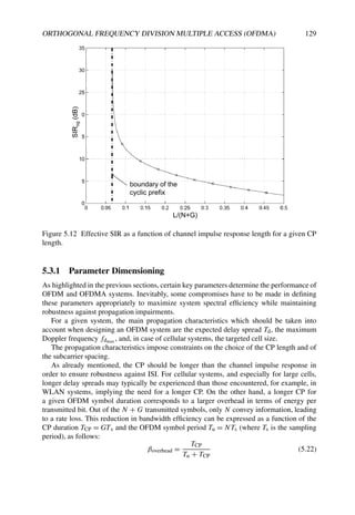
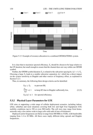
![ORTHOGONAL FREQUENCY DIVISION MULTIPLE ACCESS (OFDMA) 131
The ‘normal’ parameterization of the LTE downlink uses a f = 15 kHz subcarrier
spacing with a CP length of approximately 5 µs. This subcarrier spacing is a compromise
between the percentage overhead of the CP and the sensitivity to frequency offsets. A 15 kHz
subcarrier spacing is sufficiently large to allow for high mobility and to avoid the need for
closed-loop frequency adjustments.
In addition to the normal parameterization,it is possible to configure LTE with an extended
CP of length approximately 17 µs.2 This is designed to ensure that even in large suburban
and rural cells, the delay spread should be contained within the CP. This, however, comes at
the expense of a higher overhead from the CP as a proportion of the total system transmission
resources.
LTE is also designed to support a multi-cell broadcast transmission mode known as
Multimedia Broadcast Single Frequency Network (MBSFN), in which the UE receives and
combines synchronized signals from multiple cells. In this case the relative timing offsets
from the multiple cells must all be received at the UE’s receiver within the CP duration, if ISI
is to be avoided, thus requiring a significantly longer CP. In order to avoid a further overhead,
the sub-carrier spacing is halved in this case, to allow the OFDM symbol length to be doubled
at the expense of increasing the sensitivity to mobility and frequency errors. An extended CP
of length of approximately 33 µs can therefore be provided while remaining 1
4 of OFDM
symbol length. The MBSFN transmission mode is discussed in more detail in Chapter 14.
These modes and their corresponding parameters are summarized in Figure 5.14. It is
worth noticing that when LTE is configured with the normal CP length, the CP length for the
first OFDM symbol in each 0.5 ms interval is slightly longer than that of the next six OFDM
symbols. This characteristic is due to the need to accommodate an integer number of OFDM
symbols, namely 7, into each 0.5 ms interval,with assumed FFT block-lengths of 2048.
The actual FFT size and sampling frequency for the LTE downlink are not specified.
However, the above parameterizations are designed to be compatible with a sampling
frequency of 30.72 MHz. Thus, the basic unit of time in the LTE specifications, of which
all other time periods are a multiple, is defined as Ts = 1/30.72 µs. This is itself chosen for
backward compatibility with UMTS, for which the chip rate is 3.84 MHz – exactly one eighth
of the assumed LTE sampling frequency.
In the case of a 20 MHz system bandwidth, an FFT order of 2048 may be assumed for
efficient implementation. However, in practice the implementer is free to use other Discrete
Fourier Transform sizes.
Lower sampling frequencies (and proportionally lower FFT orders) are always possible
to reduce RF and baseband processing complexity for narrower bandwidth deployments: for
example, for a 5 MHz system bandwidth the FFT order and sampling frequency could be
scaled down to 512 and fs = 7.68 MHz respectively, while only 300 subcarriers are actually
modulated with data.
For the sake of simplifying terminal implementation, the direct current (d.c.) subcarrier
is left unused, in order to avoid d.c. offset errors in direct conversion receivers. Figure 5.15
graphically depicts the subcarrier allocations in a typical LTE deployment.
The OFDMA parameters used in the downlink are defined in the 3GPP Technical
Specification in [22].
2The length of the extended CP is 1
4 of the OFDM symbol.](https://image.slidesharecdn.com/ltefromtheorytopractise-240124145854-b0067765/85/LTE_from_Theory_to_Practise-pdf-160-320.jpg)

![ORTHOGONAL FREQUENCY DIVISION MULTIPLE ACCESS (OFDMA) 133
• OFDM is a mature technology.
• It is already widely deployed and is especially suited for broadcast or downlink
applications because of the low receiver complexity while requiring a high transmitter
complexity (expensive PA).
• It benefits from efficient implementation by means of the FFT.
• It achieves high transmission rates of broadband transmission, with low receiver
complexity.
• It makes use of a CP to avoid ISI, enabling block-wise processing.
• It exploits orthogonal subcarriers to avoid the spectrum wastage associated with inter-
subcarrier guard-bands.
• The parameterization allows the system designer to balance tolerance of Doppler and
delay spread depending on the deployment scenario.
• It can be extended to a multiple-access scheme, OFDMA, in a straightforward manner.
These factors together have made OFDMA the technology of choice for the LTE
downlink.
References3
[1] R. W. Chang, ‘Synthesis of Band-limited Orthogonal Signals for Multichannel Data
Transmission’. Bell Systems Technical Journal, Vol. 46, pp. 1775–1796, December 1966.
[2] B. R. Saltzberg, ‘Performance of an Efficient Parallel Data Transmission System’. IEEE Trans.
on Communications, Vol. 15, pp. 805–811, December 1967.
[3] S. B. Weinstein and P. M. Ebert, ‘Data Transmission by Frequency-Division Multiplexing using
the Discrete Fourier Transform’. IEEE Trans. on Communications, Vol. 19, pp. 628–634, October
1971.
[4] A. Peled and A. Ruiz, ‘Frequency Domain Data Transmission using Reduced Computational
Complexity Algorithms’ in Proc. IEEE International Conference on Acoustics, Speech and Signal
Processing, Vol. 5, pp. 964–967, April 1980.
[5] L. J. Cimini, ‘Analysis and Simulation of Digital Mobile Channel using Orthogonal Frequency
Division Multiplexing’. IEEE Trans. on Communications, Vol. 33, pp. 665–675, July 1985.
[6] G. H. Golub and C. F. Van Loan, Matrix Computations. John Hopkins University Press, 1996.
[7] R. A. Horn and C. R. Johnson, Matrix Analysis. Cambridge University Press, 1990.
[8] S. N. Bernstein, ‘On the Work of P. L. Chebyshev in Probability Theory’. The Scientific Legacy
of P. L. Chebyshev. First Part: Mathematics, edited by S. N. Bernstein. Academiya Nauk SSSR,
Moscow-Leningrad, p. 174, 1945.
[9] T. Henk, Understanding Probability: Chance Rules in Everyday Life. Cambridge University Press,
2004.
[10] X. Li and L. J. Cimini, ‘Effects of Clipping and Filtering on the Performance of OFDM’. IEEE
Comm. Lett., Vol. 2, pp. 131–133, May 1998.
3All web sites confirmed 18th December 2008.](https://image.slidesharecdn.com/ltefromtheorytopractise-240124145854-b0067765/85/LTE_from_Theory_to_Practise-pdf-162-320.jpg)
![134 LTE – THE UMTS LONG TERM EVOLUTION
[11] L. Wane and C. Tellambura, ‘A Simplified Clipping and Filtering Technique for PAPR Reduction
in OFDM Systems’. IEEE Sig. Proc. Lett., Vol. 12, pp. 453–456, June 2005.
[12] J. Armstrong, ‘Peak to Average Power Reduction for OFDM by Repeated Clipping and Frequency
Domain Filtering’. Electronics Letters, Vol. 38, pp. 246–247, February 2002.
[13] A. Jayalath, ‘OFDM for Wireless Broadband Communications (Peak Power Reduction, Spectrum
and Coding)’. PhD thesis, School of Computer Science and Software Engineering, Monash
University, 2002.
[14] A. Jones, T. Wilkinson, and S. Barton, ‘Block Coding Scheme for Reduction of Peak to Mean
Envelope Power Ratio of Multicarrier Transmission Schemes’. Electronics Letters, Vol. 30,
pp. 2098–2099, December 1994.
[15] C. Tellambura, ‘Use of M-sequence for OFDM Peak-to-Average Power Ratio Reduction’.
Electronics Letters, Vol. 33, pp. 1300–1301, July 1997.
[16] Y. Li and L. J. Cimini, ‘Bounds on the Interchannel Interference of OFDM in Time-Varying
Impairments’. IEEE Trans. on Communications, Vol. 49, pp. 401–404, March 2001.
[17] X. Cai and G. B. Giannakis, ‘Bounding Performance and Suppressing Intercarrier Interference in
Wireless Mobile OFDM’. IEEE Trans. on Communications, Vol. 51, pp. 2047–2056, March 2003.
[18] J. Heiskala and J. Terry, OFDM Wireless LANs: A Theoretical and Practical Guide. SAMS
Publishing, 2001.
[19] L. Hanzo and T. Keller, OFDM And MC-CDMA: A Primer. Wiley-IEEE Press, 2006.
[20] A. G. Burr, ‘Irreducible BER of COFDM on IIR channel’. Electronics Letters, Vol. 32, pp. 175–
176, February 1996.
[21] R. Nogueroles, M. Bossert, A. Donder, and V. Zyablov, ‘Improved Performance of a Random
OFDMA Mobile Communication System’ in Proc. IEEE Vehicular Technology Conference,
Vol. 3, pp. 2502–2506, May 1998.
[22] 3GPP Technical Specification 36.321, ‘Evolved Universal Terrestrial Radio Access (E-UTRA);
Physical Channels and Modulation (Release 8)’, www.3gpp.org.](https://image.slidesharecdn.com/ltefromtheorytopractise-240124145854-b0067765/85/LTE_from_Theory_to_Practise-pdf-163-320.jpg)
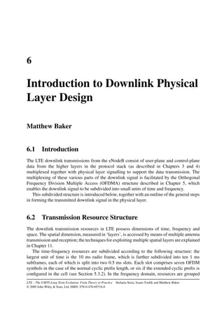

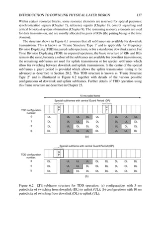
![138 LTE – THE UMTS LONG TERM EVOLUTION
6.3 Signal Structure
The role of the physical layer is primarily to translate data into a reliable signal for
transmission across the radio interface between the eNodeB and the User Equipment (UE).
Each block of data is first protected against transmission errors, usually first with a Cyclic
Redundancy Check (CRC), and then with channel coding; these aspects are explained in
detail in Chapter 10. After channel coding, the steps in the formation of the downlink LTE
signal are illustrated in Figure 6.3.
Scrambling
Modulation
mapper
RE
mapper
OFDM signal
generation
Layer
mapper
Precoding
Scrambling
Modulation
mapper
RE
mapper
OFDM signal
generation
Codewords Layers eNB antenna ports
Figure 6.3 General signal structure for LTE downlink. Reproduced by permission of © 3GPP.
The initial scrambling stage is applied to all downlink physical channels, and serves
the purpose of interference rejection. The scrambling sequence in all cases uses an order-
31 Gold code, which can provide 231 sequences which are not cyclic shifts of each other.
Gold codes [1, 2] also possess the attractive feature that they can be generated with very
low implementation complexity, as they can be derived from the modulo-2 addition of two
maximum-length sequences (otherwise known as M-sequences), which can be generated
from a simple shift-register.2 A shift-register implementation of the LTE scrambling sequence
generator is illustrated in Figure 6.4.
Figure 6.4 Shift-register implementation of scrambling sequence generator.
2Gold Codes were also used in WCDMA (Wideband Code Division Multiple Access), for the uplink long
scrambling codes.](https://image.slidesharecdn.com/ltefromtheorytopractise-240124145854-b0067765/85/LTE_from_Theory_to_Practise-pdf-167-320.jpg)

![140 LTE – THE UMTS LONG TERM EVOLUTION
Some suitable techniques for this process are described in Chapter 8, based on the pilot
signals (known in LTE as reference signals) which are inserted into the downlink signal.
Chapter 9 describes the parts of the downlink signal which carry data originating from
higher protocol layers, including the Physical Broadcast Channel (PBCH), the Physical
Downlink Shared Channel (PDSCH) and, in case of MBMS transmission, the Physical
Multicast Channel (PMCH). In addition, the design of the downlink control signalling is
explained, including its implications for the ways in which downlink transmission resources
may be allocated to different users for data transmission.
The downlink physical channels described in the following chapters are summarized in
Figure 6.5, together with their relationship to the higher-layer channels.
The subsequent chapters explain the key techniques which enable these channels to make
efficient use of the radio spectrum: channel coding and link adaptation are explained in
Chapter 10, the LTE schemes for exploiting multiple antennas are covered in Chapter 11, and
techniques for effective scheduling of transmission resources to multiple users are described
in Chapter 12.
References
[1] W. Huffman and V. Pless, Handbook of Coding Theory, vol II. Amsterdam: North-Holland, 1998.
[2] R. McEliece, Finite Fields for Computer Scientists and Engineers. Boston, MA: Kluwer Academic
Publishers, 2003.](https://image.slidesharecdn.com/ltefromtheorytopractise-240124145854-b0067765/85/LTE_from_Theory_to_Practise-pdf-169-320.jpg)


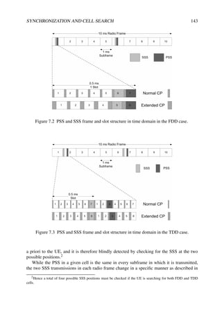
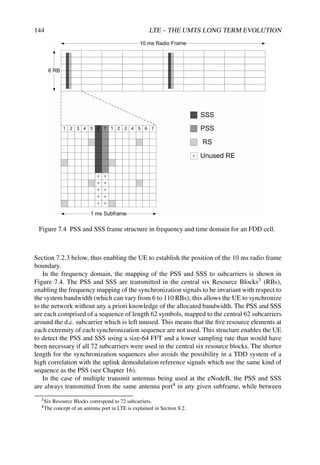
![SYNCHRONIZATION AND CELL SEARCH 145
different subframes they may be transmitted from different antenna ports in order to benefit
from time-switched antenna diversity.
The particular sequences which are transmitted for the PSS and SSS in a given cell are
used to indicate the physical layer cell identity to the UE. There are 504 unique physical layer
cell identities in LTE, grouped into 168 groups of three identities. The three identities in a
group would usually be assigned to cells under the control of the same eNodeB. Three PSS
sequences are used to indicate the cell identity within the group, and 168 SSS sequences are
used to indicate the identity of the group.5
The PSS uses sequences known as Zadoff–Chu. This category of sequences is widely used
in LTE, including for random access preambles and the uplink reference symbols in addition
to the PSS. Therefore, the following section is devoted to an explanation of the fundamental
principles behind these sequences, before discussing the specific constructions of the PSS
and SSS sequences in the subsequent sections.
7.2.1 Zadoff–Chu Sequences
Zadoff–Chu (ZC) sequences (also known as Generalized Chirp-Like (GCL) sequences) are
named after the papers [1] and [2]. They are non-binary unit-amplitude sequences [3], which
satisfy a Constant Amplitude Zero Autocorrelation (CAZAC) property. CAZAC sequences
are complex signals of the form ejαk . The ZC sequence of odd-length NZC is given by
aq(n) = exp −j2πq
n(n + 1)/2 + ln
NZC
(7.1)
where q ∈ {1, . . . , NZC − 1} is the ZC sequence root index, n = 0, 1, . . . , NZC − 1, l ∈ N
is any integer. In LTE l = 0 is used for simplicity.
ZC sequences have the following important properties.
Property 1. A ZC sequence has constant amplitude, and its NZC-point DFT also has
constant amplitude. The constant amplitude property limits the Peak-to-Average Power Ratio
(PAPR) and generates bounded and time-flat interference to other users. It also simplifies the
implementation as only phases need to be computed and stored, not amplitudes.
Property 2. ZC sequences of any length have ‘ideal’ cyclic autocorrelation (i.e. the
correlation with the circularly shifted version of itself is a delta function). The zero
autocorrelation property may be formulated as:
rkk(σ) =
NZC−1
n=0
ak(n)a∗
k [(n + σ)] = δ(σ) (7.2)
where rkk(·) is the discrete periodic autocorrelation function of ak at lag σ. This property is
of major interest when the received signal is correlated with a reference sequence and the
received reference sequences are misaligned. As an example, Figure 7.5 shows the difference
between the periodic autocorrelation of a truncated Pseudo Noise (PN) sequence (as used
in WCDMA [4]) and a ZC sequence. Both are 839 symbols long in this example. The ZC
periodic autocorrelation is exactly zero for σ = 0 and it is non-zero for σ = 0, whereas the
PN periodic autocorrelation shows significant peaks, some above 0.1, at non-zero lags.
5It may become possible to reserve a subset of the available physical layer cell identities for a specific use, such
as to indicate that the cell is a Home eNodeB.](https://image.slidesharecdn.com/ltefromtheorytopractise-240124145854-b0067765/85/LTE_from_Theory_to_Practise-pdf-174-320.jpg)
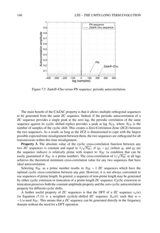


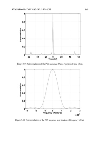
![150 LTE – THE UMTS LONG TERM EVOLUTION
From the point of view of the UE, the selected root combination satisfies time-domain
root-symmetry, in that sequences 29 and 34 are complex conjugates of each other and can be
detected with a single correlator, thus allowing for some complexity reduction.
The UE must detect the PSS without any a priori knowledge of the channel, so non-
coherent correlation is required for PSS timing detection. A maximum likelihood detector,
as explained in Section 7.3, finds the timing offset m∗
M that corresponds to the maximum
correlation, i.e.
m∗
M = argmaxm
N−1
i=0
Y[i + m]S∗
M[i]
2
(7.4)
where i is time index, m is the timing offset, N is the PSS time domain signal length, Y[i] is
the received signal at time instant i and SM [i] is the PSS with root M replica signal at time i
as defined in Equation (7.3).
7.2.3 Secondary Synchronization Signal (SSS) Sequences
The SSS sequences are based on maximum length sequences, known as M-sequences, which
can be created by cycling through every possible state of a shift register of length n. This
results in a sequence of length 2n − 1.
Figure 7.11 SSS sequence mapping.](https://image.slidesharecdn.com/ltefromtheorytopractise-240124145854-b0067765/85/LTE_from_Theory_to_Practise-pdf-179-320.jpg)
![SYNCHRONIZATION AND CELL SEARCH 151
Each SSS sequence is constructed by interleaving, in the frequency-domain,two length-31
BPSK-modulated secondary synchronization codes, denoted here SSC1 and SSC2, as shown
in Figure 7.11.
These two codes are two different cyclic shifts of a single length-31 M-sequence. The
cyclic shift indices of the M-sequences are derived from a function of the physical layer cell
identity group (as given in Table 6.11.2.1-1 in [5]). The two codes are alternated between the
first and second SSS transmissions in each radio frame. This enables the UE to determine the
10 ms radio frame timing from a single observation of a SSS, which is important for UEs
handing over to LTE from another radio access technology. For each transmission, SSC2 is
scrambled by a sequence that depends on the index of SSC1. The sequence is then scrambled
by a code that depends on the PSS. The scrambling code is one-to-one mapped to the
physical layer identity within the group corresponding to the target eNodeB. The sequence
construction is illustrated in Figure 7.12; details of the scrambling operations are given in [5].
Figure 7.12 SSS sequence generation.
The SSS sequences have good frequency-domainproperties, being spectrally flat as shown
in Figure 7.13. As in the case of the PSS, the SSS can be detected with a frequency offset
up to ±7.5 kHz. In the time domain, the cross-correlation between any cyclic shifts of an
SSS sequence is not as good as for classical M-sequences (for which the cross-correlation is
known to be −1), owing to the effects of the scrambling operations. Figure 7.14 illustrates
the cross-correlation in frequency domain.
From the point of view of the UE, the SSS detection is done after the PSS detection, and
the channel can therefore be assumed to be known based on the PSS sequence. It follows that](https://image.slidesharecdn.com/ltefromtheorytopractise-240124145854-b0067765/85/LTE_from_Theory_to_Practise-pdf-180-320.jpg)

![SYNCHRONIZATION AND CELL SEARCH 153
Table 7.1 Cell identification test parameters.
Parameter (e-NodeB) Unit Cell1 Cell2 Cell3
Relative delay of 1st path for synchronous case ms 0 0 Half CP length
Relative delay of 1st path for asynchronous case ms 0 1.5 3
SNR dB 5.18 0.29 −0.75 in worst case
PSS Physical layer ID for case different PSS PSS1 PSS2 PSS3
PSS Physical layer ID for case equal PSS PSS1 PSS2 PSS1
a coherent detection method as described in Section 7.3 in Equation (7.8) can be applied:
Ŝm = argmin
S
N
n=1
|y[n] − S[n, n] ˆ
hn|2
(7.5)
where the symbols S[n, n] represent the SSS sequences and ˆ
hn are the estimated channel
coefficients.
However, in the case of synchronized neighbouring eNodeBs, the performance of a
coherent detector can be degraded. This is because if an interfering eNodeB employs the
same PSS as the one used by the target cell, the phase difference between the two eNodeBs
can have an impact on the quality of the estimation of the channel coefficients. On the other
hand, the performance of a non-coherent detector degrades if the coherence bandwidth of the
channel is less than the six resource blocks occupied by the SSS.
In order to reduce the complexity of the SSS detector, the equivalence between M-
sequence matrices and Walsh–Hadamard matrices can be exploited [6]. Using this property,
a fast M-sequence transform is equivalent to a fast Walsh–Hadamard transform with index
remapping. Thanks to this property the complexity of the SSS detector is reduced to N log2 N
where N = 32.
7.2.4 Cell Search Performance
A key requirement for the LTE cell search procedure is that the delay for the UE to detect a
newly appearing cell and report it to the serving eNodeB should be less than a prescribed
acceptable threshold. As explained in Chapter 13, the serving eNodeB uses the reported
information to prepare intra- or inter-frequency handover.
The performance requirements for new cell identification specified in 3GPP are defined
for real and generic deployment conditions. A multicell environment consisting of three cells
is assumed, with different transmitted powers from each eNodeB. Scenarios covering both
synchronized and unsynchronized eNodeBs are analysed, as summarized in Table 7.1. For
the propagation channel, various multipath fading conditions with associated UE speeds
are considered, and in particular ETU5 (Extended Typical Urban with UE speed 5 km/h),
ETU300 (UE speed 300 km/h) and EPA5 (Extended Pedestrian A with UE speed 5 km/h).6
At the UE, two receive antennas are assumed. Further details of the assumed scenarios can
be found in [7].
6Further details of these propagation models are given in Chapter 21.](https://image.slidesharecdn.com/ltefromtheorytopractise-240124145854-b0067765/85/LTE_from_Theory_to_Practise-pdf-182-320.jpg)
![154 LTE – THE UMTS LONG TERM EVOLUTION
Table 7.2 Cell identification test scenarios.
Test case Cell3 Cell1 Cell2
(synch, asynch eNodeBs) (Target) (Interference) (Interference)
1,5 PSS3 SSS3a, SSS3b PSS1 SSS1a, SSS1b PSS2 SSS2a, SSS2b
2,6 PSS1 SSS3a, SSS3b PSS1 SSS1a, SSS1b PSS2 SSS2a, SSS2b
3,7 PSS1 SSS1a, SSS3b PSS1 SSS1a, SSS1b PSS2 SSS2a, SSS2b
4,8 PSS3 SSS1a, SSS1b PSS1 SSS1a, SSS1b PSS2 SSS2a, SSS2b
−1 −0.5 0 0.5 1 1.5
200
250
300
350
400
450
SNR(dB)
90%
acquisition
time
(ms)
Case1
Case2
Case3
Case4
(See Table 7.2)
Figure 7.15 Cell search performance with synchronous eNodeBs. Reproduced by permission
of © NXP Semiconductors.
The cell search performance is measured in terms of the 90-percentile cell identification
delay, i.e. the maximum time required to detect the target cell 90% of the time. In the example
shown in Table 7.1, the target cell for detection is ‘Cell3’.
Typical performance is shown in Figures 7.15 and 7.16, without assuming any margin
for non-ideal UE receiver implementation and without including any reporting delay for the
Reference Signal Received Power (RSRP) measurement. Various simulation scenarios have
been considered to analyse the impact on the detection performance of different PSS and SSS
sequences combination as indicated in Table 7.2. More detailed performance results can be
found in [8].
To arrive at performance figures (in terms of acquisition time) for the initial synchro-
nization case (as opposed to new cell identification) the time taken for successful detection
would be adapted by considering the decoding of the PBCH instead of the reporting of
measurements made on the reference signals of the target cell.](https://image.slidesharecdn.com/ltefromtheorytopractise-240124145854-b0067765/85/LTE_from_Theory_to_Practise-pdf-183-320.jpg)
![SYNCHRONIZATION AND CELL SEARCH 155
−1 −0.5 0 0.5 1 1.5
150
200
250
300
350
400
SNR(dB)
90%
acquisition
time
(ms)
Case5
Case6
Case7
Case8
(See Table 7.2)
Figure 7.16 Cell search performance with asynchronous eNodeBs. Reproduced by
permission of © NXP Semiconductors.
For the case of inter-frequency handover, the performance can be derived from the
intra-frequency performance: timing constraints would be applied based on the inter-
frequency monitoring gap pattern provided by the eNodeB for performing the necessary
synchronization and measurements, as explained in Chapter 13.
7.3 Coherent Versus Non-Coherent Detection
As explained above, both coherent and non-coherent detection may play a part in the
synchronization procedures: in the case of the PSS, non-coherent detection is used, while
for SSS sequence detection, coherent or non-coherent techniques can be used.
This section gives some theoretical background to the difference between coherent and
non-coherent detection. From a conceptual point of view, a coherent detector takes advantage
of knowledge of the channel, while a non-coherent detector uses an optimization metric
corresponding to the average channel statistics.
We consider a generic system model where the received sequence ym at time instant
m is given by Equation (7.6), where the matrix Sm = diag [sm,1, . . . , sm,N ] represents the
transmitted symbol at time instant m and h = [h1, . . . , hN ]T is the channel vector, i.e.
ym = Smh + νm (7.6)
where νm is zero-mean complex Gaussian noise with variance σ2. In the following sections,
expressions for coherent and non-coherent detection are derived.](https://image.slidesharecdn.com/ltefromtheorytopractise-240124145854-b0067765/85/LTE_from_Theory_to_Practise-pdf-184-320.jpg)
![156 LTE – THE UMTS LONG TERM EVOLUTION
7.3.1 Coherent Detection
Maximum Likelihood (ML) coherent detection of a transmitted sequence consists of finding
the sequence which maximizes the probability that the sequence was transmitted, conditioned
on the knowledge of the channel. Coherent detectors therefore require channel estimation to
be performed first.
Since the noise is assumed to be independently identically distributed (i.i.d.) and detection
is symbol-by-symbol, we focus on one particular symbol interval, neglecting the time instant
without loss of generality. The problem becomes
Ŝ = argmax
S
Pr(y | S, h) = argmax
S
1
(πN0)N
exp −
y − Sh 2
N0
(7.7)
Maximizing Equation (7.7) is equivalent to minimizing the magnitude of the argument of the
exponential, i.e.
Ŝ = argmin
S
( y − Sh 2
)
= argmin
S
N
n=1
|yn − Sn,nhn|2
(7.8)
Equation (7.8) is a minimum squared Euclidean distance rule where the symbols Sn,n are
weighted by the channel coefficient hn.
7.3.2 Non-Coherent Detection
When channel knowledge is not available or cannot be exploited, non-coherent detection can
be used. The trick consists of removing the dependency on a particular channel condition
by averaging over the distribution of the random channel coefficients h. The ML detection
problem maximizes the following conditional probability:
Ŝ = argmax
S
Pr(y | S)
= argmax
S
E
h
[Pr(y | S, h)] =
h
Pr(y | S, h) Pr(h) dh
=
h
1
(π N0)N
exp −
ym − Smh 2
N0
Pr(h) dh (7.9)
Substituting the PDF of an AWGN channel, the ML non-coherent detector yields
Ŝ = argmax
S
1
NN
0 π2N det(Rh)
h
exp −
y − Sh 2
N0
+ hH
R−1
h h
(7.10)
It can be shown [9] that the solution of the integral in Equation (7.10) is given by
h
exp −
y − Sh 2
N0
+ hH
R−1
h h
=
πN
det(A)
exp −
1
N0
yH
y +
1
N0
yH
S(SH
S + N0R−1
h )−1
SH
y (7.11)](https://image.slidesharecdn.com/ltefromtheorytopractise-240124145854-b0067765/85/LTE_from_Theory_to_Practise-pdf-185-320.jpg)
![SYNCHRONIZATION AND CELL SEARCH 157
Note that SHS = I under the assumption of normalization by the signal energy.
The maximization in Equation (7.9) is done over the input symbols S, so all terms which
do not depend on S can be discarded. Hence
Ŝ = argmax
S
{exp[yH
S(SH
S + N0R−1
h )−1
SH
y]} = argmax
S
{yH
S(I + N0R−1
h )−1
SH
y}
(7.12)
where the last equality holds because of the monotonicity of the exponential function.
Depending on the form of Rh, the ML non-coherent detector can be implemented in different
ways. For example, in the case of frequency non-selective channel, the channel correlation
matrix can be written as Rh = σ2
h V where V is the all ones matrix. It follows that
(I + N0R−1
h )−1
=
σ2
h
N
V +
σ2
h
N
(α−1
− 1)I
where α = σ2
h /N0 + 1. With this hypothesis the quadratic expression in Equation (7.12) can
be written as
yH
S(I + N0R−1
h )−1
SH
y =
σ2
h
N N0
(α−1
− 1) y 2
+
N
i=1
S[i, i]y[i]
2
(7.13)
The non-coherent ML detector is thus obtained by the maximization of
Ŝ = argmax
S
N
i=1
S[i, i]y[i]
2
(7.14)
References7
[1] J. D. C. Chu, ‘Polyphase Codes with Good Periodic Correlation Properties’. IEEE Trans. on
Information Theory, Vol. 18, pp. 531–532, July 1972.
[2] R. Frank, S. Zadoff and R. Heimiller, ‘Phase Shift Pulse Codes With Good Periodic Correlation
Properties’. IEEE Trans. on Information Theory, Vol. 8, pp. 381–382, October 1962.
[3] B. M. Popovic, ‘Generalized Chirp-Like Polyphase Sequences with Optimum Correlation
Properties’. IEEE Trans. on Information Theory, Vol. 38, pp. 1406–1409, July 1992.
[4] 3GPP Technical Specification 25.213, ‘Spreading and modulation (FDD) (Release 8)’,
www.3gpp.org.
[5] 3GPP Technical Specification 36.211, ‘Physical Channels and Modulation (Release 8)’,
www.3gpp.org.
[6] M. Cohn and A. Lempel, ‘On Fast M-Sequence Transforms’. IEEE Trans. on Information Theory,
Vol. 23, pp. 135–137, January 1977.
[7] Texas Instruments, NXP, Motorola, Ericsson, and Nokia, ‘R4-072215: Simulation Assumptions
for Intra-frequency Cell Identification’, www.3gpp.org 3GPP TSG RAN WG4, meeting 45, Jeju,
Korea, November 2007.
[8] NXP, ‘R4-080691: LTE Cell Identification Performance in Multi-cell Environment’, www.3gpp.org
3GPP TSG RAN WG4, meeting 46bis, Shenzen, China, February 2008.
[9] D. Reader, ‘Blind Maximum Likelihood Sequence Detection over Fast Fading Communication
Channels’, Dissertation, University of South Australia, Australia, August 1996.
7All web sites confirmed 18th December 2008.](https://image.slidesharecdn.com/ltefromtheorytopractise-240124145854-b0067765/85/LTE_from_Theory_to_Practise-pdf-186-320.jpg)

![160 LTE – THE UMTS LONG TERM EVOLUTION
requires accurate estimation of the propagation channel. This is true for both downlink and
uplink, and for both Frequency Division Duplex (FDD) and Time Division Duplex (TDD).
The main advantage of coherent detection is the simplicity of the implementation
compared to the more complex algorithms required by non-coherent detection for equivalent
performance. However, this simplicity comes at a price, namely the overhead needed in order
to be able to estimate the channel. A common and simple way to estimate the channel is
to exploit known signals which do not carry any data, but which therefore cause a loss in
spectral efficiency. In general, it is not an easy task to find the optimal trade-off between
minimizing the spectral efficiency loss due to the overhead and providing adequate ability to
track variations in the channel.
Other possible techniques for channel estimation include the use of a priori knowledge
of a parametric model of the channel, exploiting the correlation properties of the channel, or
using blind estimation.
Once synchronization between an eNodeB and a UE has been achieved, the main
characteristic of the LTE physical processing architecture (shared with earlier systems such
as GSM and UMTS) is that of being a coherent communication system, for which purpose
known reference signals are inserted into the transmitted signal structure.
In general, a variety of methods can be used to embed reference signals into a transmitted
signal. The reference signals can be multiplexed with the data symbols (which are unknown
at the receiver) in either the frequency, time or code domains (the latter being used in
the case of the common pilot channel in the UMTS downlink). A special case of time
multiplexing, known as preamble-based training, involves transmitting the reference signals
at the beginning of each data burst. Multiplexing-based techniques have the advantage of
low receiver complexity, as the symbol detection is decoupled from the channel estimation
problem. Alternatively, reference symbols may be superimposed on top of unknown data,
without the two necessarily being orthogonal. Note that multiplexing reference signals in the
code domain is a particular type of superposition with a constraint on orthogonality between
known reference signals and the unknown data. A comprehensive analysis of the optimization
of reference signal design can be found in [1,2].
Orthogonal reference signal multiplexing is by far the most common technique. For
example, to facilitate channel estimation in the UMTS downlink, two types of orthogonal
reference signal are provided. The first is code-multiplexed, available to all users in a cell,
and uses a specific spreading code which is orthogonal to the codes used to spread the users’
data. The second type is time-multiplexed dedicated reference signals, which may in some
situations be inserted into the users’ data streams [3].
In the LTE downlink, the OFDM transmission can be described by a two-dimensional
lattice in time and frequency, as shown in Figure 6.1 and described in Chapter 6. This
structure facilitates the multiplexing of the Reference Signals (RSs), which are mapped to
specific Resource Elements (REs) of the two-dimensional lattice in Figure 6.1 according to a
pattern explained in Section 8.2.
In order to estimate the channel as accurately as possible, all correlations between channel
coefficients in time, frequency and space should be taken into account. Since reference
signals are sent only on particular OFDM REs (i.e. on particular OFDM symbols on particular
subcarriers), channel estimates for the REs which do not bear reference signals have to be
computed via interpolation. The optimal interpolating channel estimator in terms of mean
squared error is based on a two-dimensional Wiener filter interpolation [4]. Due to the high](https://image.slidesharecdn.com/ltefromtheorytopractise-240124145854-b0067765/85/LTE_from_Theory_to_Practise-pdf-188-320.jpg)
![REFERENCE SIGNALS AND CHANNEL ESTIMATION 161
complexity of such a filter, a trade-off between complexity and accuracy is achieved by using
one-dimensional filters. In Sections 8.4, 8.5 and 8.6 the problem of channel estimation is
approached from a theoretical point of view, and some possible solutions are described.
The work done in the field of channel estimation, and the corresponding literature
available, is vast. Nevertheless many challenges still remain, and we refer the interested
reader to [2] and [5] for a general survey of open issues in this area.
8.2 Design of Reference Signals in LTE
In the LTE downlink, three different types of reference signal are provided [6]:
• Cell-specific RSs (often referred to as ‘common’ RSs, as they are available to all UEs
in a cell).
• UE-specific RSs, which may be embedded in the data for specific UEs.
• MBSFN-specific RSs, which are only used for Multimedia Broadcast Single Fre-
quency Network (MBSFN) operation and are discussed further in Chapter 14.
8.2.1 Cell-Specific Reference Signals
References [7, 8] show that in an OFDM-based system an equidistant arrangement of
reference symbols in the lattice structure achieves the minimum mean squared error estimate
of the channel. Moreover, in the case of a uniform reference symbol grid, a ‘diamond shape’
in the time-frequency plane can be shown to be optimal.
In LTE, the arrangement of the symbols making up the cell-specific RSs in the time-
frequency two-dimensional lattice follows these principles. Figure 8.2 illustrates the refer-
ence symbol arrangement for the normal CP length.1
The LTE system has been conceived to work under high-mobility assumptions, in contrast
to WLAN systems which are generally optimized for pedestrian-level mobility. WLAN
systems typically use a preamble-based training sequence, the frequency of which governs
the degree of mobility they can support.
The required spacing in time between the reference symbols can be obtained by
considering the maximum Doppler spread (highest speed) to be supported, which for LTE
corresponds to 500 km/h [9]. The Doppler shift is fd = (fc v/c) where fc is the carrier
frequency, v is the UE speed in metres per second, and c is the speed of light (3 · 108 m/s).
Considering fc = 2 GHz and v = 500 km/h, then the Doppler shift is fd 950 Hz.
According to Nyquist’s sampling theorem, the minimum sampling frequency needed in order
to reconstruct the channel is therefore given by Tc = 1/(2fd) 0.5 ms under the above
assumptions. This implies that two reference symbols per slot are needed in the time domain
in order to estimate the channel correctly.
In the frequency direction there is one reference symbol every six subcarriers on each
OFDM symbols which includes reference symbol, but these are staggered so that within
1In the case of the extended CP, the arrangement of the reference symbols slightly changes, but the explanations
in the rest of the chapter are no less valid. The detailed arrangement of reference symbols for the extended CP can
be found in [6].](https://image.slidesharecdn.com/ltefromtheorytopractise-240124145854-b0067765/85/LTE_from_Theory_to_Practise-pdf-189-320.jpg)
![162 LTE – THE UMTS LONG TERM EVOLUTION
Frequency
Time
Figure 8.2 Cell-specific reference symbol arrangement in the case of normal CP length for
one antenna port. Reproduced by permission of © 3GPP.
each Resource Block (RB) there is one reference symbol every 3 subcarriers, as shown in
Figure 8.2. This spacing is related to the expected coherence bandwidth of the channel, which
is in turn related to the channel delay spread. In particular the 90% and 50% coherence
bandwidths2 are given respectively by Bc,90% = 1/50στ and Bc,50% = 1/5στ where στ is the
r.m.s delay spread. In [10] the maximum r.m.s channel delay spread considered is 991 ns,
corresponding to Bc,90% = 20 kHz and Bc,50% = 200 kHz. In LTE the spacing between two
reference symbols in frequency, in one RB, is 45 kHz, thus allowing the expected frequency-
domain variations of the channel to be resolved.
The LTE downlink has been specifically designed to work with multiple transmit antennas,
as is discussed in detail in Chapter 11. RS patterns are therefore defined for multiple ‘antenna
ports’ at the eNodeB. An antenna port may in practice be implemented either as a single
physical transmit antenna, or as a combination of multiple physical antenna elements. In
either case, the signal transmitted from each antenna port is not designed to be further
deconstructed by the UE receiver: the transmitted RS corresponding to a given antenna port
defines the antenna port from the point of view of the UE, and enables the UE to derive a
channel estimate for that antenna port – regardless of whether it represents a single radio
channel from one physical antenna or a composite channel from a multiplicity of physical
antenna elements together comprising the antenna port.
Up to four cell-specific antenna ports may be used by a LTE eNodeB, thus requiring
the UE to derive up to four separate channel estimates.3 For each antenna port, a different
2Bc,x% is the bandwidth where the autocorrelation of the channel in the frequency domain is equal to x%.
3Any MBSFN and UE-specific RSs, if transmitted, constitute additional independent fifth and sixth antenna ports
respectively in the LTE specifications.](https://image.slidesharecdn.com/ltefromtheorytopractise-240124145854-b0067765/85/LTE_from_Theory_to_Practise-pdf-190-320.jpg)
![REFERENCE SIGNALS AND CHANNEL ESTIMATION 163
RS pattern is designed, with particular attention having been given to the minimization of the
intra-cell interference between the multiple transmit antenna ports. In Figure 8.3 Rp indicates
that the resource element is used for the transmission of an RS on antenna port p. In particular
when a resource element is used to transmit an RS on one antenna port, the corresponding
resource element on the other antenna ports is set to zero to limit the interference.
From Figure 8.3 it can be noticed that the density of RS for the third and fourth antenna
ports is half that of the first two; this is to reduce the overhead in the system. Frequent
reference symbols are useful for high-speed conditions as explained above. In cells with a
high prevalence of high-speed users, the use of four antenna ports is unlikely, hence for these
conditions RSs with lower density can provide sufficient channel estimation accuracy.
All the RSs (cell-specific, UE-specific or MBSFN specific) are QPSK modulated – a
constant modulus modulation. This property ensures that the Peak-to-Average Power Ratio
(PAPR) of the transmitted waveform is kept low. The signal can be written as
rl,ns (m) =
1
√
2
[1 − 2c(2m)] + j
1
√
2
[1 − 2c(2m + 1)] (8.1)
where m is the index of the RS, ns is the slot number within the radio frame and ‘l’ is the
symbol number within the time slot. The pseudo-random sequence c(i) is comprised of a
length-31 Gold sequence, already introduced in Chapter 6, with different initialization values
depending on the type of RSs.
The RS sequence also carries unambiguously one of the 504 different cell identities, Ncell
ID .
For the cell-specific RSs, a cell-specific frequency shift is also applied, given by Ncell
ID mod6.4
This shift can avoid time-frequency collisions between common RS from up to six adjacent
cells. Avoidance of collisions is particularly important in cases when the transmission power
of the RS is boosted, as is possible in LTE up to a maximum of 6 dB relative to the
surrounding data symbols. RS power boosting is designed to improve channel estimation in
the cell, but if adjacent cells transmit high-power RS on the same REs the resulting inter-cell
interference will prevent the benefit from being realized.
8.2.2 UE-Specific Reference Signals
UE-specific RS may be transmitted in addition to the cell-specific RSs described above. They
are embedded only in the RBs to which the PDSCH is mapped for UEs which are specifically
configured (by higher-layer RRC signalling) to receive their downlink data transmissions
in this mode. If UE-specific RSs are used, the UE is expected to use them to derive the
channel estimate for demodulating the data in the corresponding PDSCH RBs. Thus the UE-
specific RS are treated as being transmitted using a distinct antenna port, with its own channel
response from the eNodeB to the UE.
A typical usage of the UE-specific RSs is to enable beamforming of the data transmissions
to specific UEs. For example, rather than using the physical antennas used for transmission
of the other (cell-specific) antenna ports, the eNodeB may use a correlated array of physical
antenna elements to generate a narrow beam in the direction of a particular UE. Such a beam
will experience a different channel response between the eNodeB and UE, thus requiring the
use of UE-specific RSs to enable the UE to demodulate the beamformed data coherently. The
use of UE-specific beamforming is discussed in more detail in Section 11.2.
4The mod6 operation is used because RSs are spaced apart by six subcarriers in the lattice grid.](https://image.slidesharecdn.com/ltefromtheorytopractise-240124145854-b0067765/85/LTE_from_Theory_to_Practise-pdf-191-320.jpg)

![REFERENCE SIGNALS AND CHANNEL ESTIMATION 165
Figure 8.4 UE-specific RS arrangement with normal CP. Reproduced by permission of
© 3GPP.
As identified in [11], the structure shown in Figure 8.4 (for the normal CP) has been
chosen because there is no collision with the cell specific RSs, and hence the presence of
a UE-specific RSs does not affect features related to the cell-specific RSs. The UE-specific
RSs have a similar pattern to that of the cell-specific RSs, which allows a UE to re-use
similar channel estimation algorithms. The density is half that of the cell-specific RS, hence
minimizing the overhead.
The corresponding pattern for use in case of the extended CP being configured in a cell
can be found in [6].
8.3 RS-Aided Channel Modelling and Estimation
The channel estimation problem is related to the channel model assumed, itself determined
by the physical propagation characteristics, including the number of transmit and receive
antennas, transmission bandwidth, carrier frequency, cell configuration and relative speed
between eNodeB and UE receivers. In general,
• The carrier frequencies and system bandwidth mainly determine the scattering nature
of the channel.
• The cell deployment governs its multipath, delay spread and spatial correlation
characteristics.
• The relative speed sets the time-varying properties of the channel.](https://image.slidesharecdn.com/ltefromtheorytopractise-240124145854-b0067765/85/LTE_from_Theory_to_Practise-pdf-193-320.jpg)
![166 LTE – THE UMTS LONG TERM EVOLUTION
The propagation conditions characterize the channel correlation function in a three-
dimensional space comprising frequency, time and spatial domains. In the general case, each
MIMO (Multiple-Input Multiple-Output) multipath channel component can experience dif-
ferent but related spatial scattering conditions leading to a full three-dimensional correlation
function across the three domains. Nevertheless, for the sake of simplicity, assuming that the
multipath components of each spatial channel experience the same scattering conditions, the
spatial correlation is independent from the other two domains and can be handled separately
from the frequency and time domain correlations.
This framework might be suboptimal in general, but is nevertheless useful in mitigating the
complexity of channel estimation as it reduces the general three-dimensional joint estimation
problem into independent estimation problems.
For a comprehensive survey of MIMO channel estimation the interested reader is referred
to [12].
In the following two subsections, we define a channel model and its corresponding
correlation properties. These are then used as the basis for an overview of channel estimation
techniques which exploit channel correlation in the context of the LTE downlink.
8.3.1 Time-Frequency Domain Correlation: The WSSUS Channel
Model
The Wide-Sense Stationary Uncorrelated Scattering (WSSUS) channel model is commonly
employed for the multipath channels experienced in mobile communications.
Neglecting the spatial dimension for the sake of simplicity, let h(τ; t) denote the time-
varying complex baseband impulse response of a multipath channel realization at time instant
t and delay τ.
When a narrowband signal x(t) is transmitted, the received narrowband signal y(t) can be
written as
y(t) =
h(τ; t)x(t − τ) dτ (8.2)
Considering the channel as a random process in the time direction t, the channel is said to
be delay Uncorrelated-Scattered (US) if
E[h(τa; t1)∗
h(τb; t2)] = φh(τa; t1, t2)δ(τb − τa) (8.3)
with E[·] being the expectation operator. According to the US assumption, two CIR
components a and b at relative respective delays τa and τb are uncorrelated if τa = τb.
The channel is Wide-Sense Stationary (WSS)-uncorrelated if
φh(τ; t1, t2) = φh(τ; t2 − t1) (8.4)
which means that the correlation of each delay component of the CIR is only a function of
the difference in time between each realization.
Hence, the second-order statistics of this model are completely described by its delay
cross-power density φh(τ; t) or by its Fourier transform, the scattering function
Sh(τ; f ) =
φh(τ; t)e−j2πf t
dt (8.5)](https://image.slidesharecdn.com/ltefromtheorytopractise-240124145854-b0067765/85/LTE_from_Theory_to_Practise-pdf-194-320.jpg)
![REFERENCE SIGNALS AND CHANNEL ESTIMATION 167
with f being the Doppler frequency. Other related functions of interest include the multipath
intensity profile
ψh(τ) = φh(τ; 0) =
Sh(τ; f ) df
the time-correlation function
φh(τ) =
φh(τ; t) dτ
and the Doppler power spectrum
Sh(f ) =
Sh(τ; f ) dτ
A more general exposition of WSSUS models is given in [13]. Classical results were
derived by Clarke [14] and Jakes [15] for the case of a mobile terminal communicating with
a stationary base station in a two-dimensional propagation geometry.
These well-known results state that
Sh(f ) ∝
1
f 2
d − f 2
(8.6)
for |f | ≤ fd, fd = (v/c)fc the maximum Doppler frequency for a mobile with relative speed
v, carrier frequency fc and propagation speed c and
φ̄h(t) ∝ J0(2πfdt) (8.7)
where J0 is the zeroth-order Bessel function. The autocorrelation function is obtained via
the inverse Fourier transform of the Power Spectral Density (PSD) (Figure 8.5 shows the
PSD of the classical Doppler spectrum described by Clarke and Jakes [14,15]). The squared
magnitude of the autocorrelation function corresponding to Clarke’s spectrum model is
plotted in Figure 8.6 where the variable φ along the x-axis is effectively a spatial lag (in
metres) normalized by the carrier wavelength. The Clarke and Jakes derivations are based on
the assumption that the physical scattering environment is chaotic and therefore the angle of
arrival of the electromagnetic wave at the receiver is a uniformly distributed random variable
in the angular domain. As a consequence, the time-correlation function is strictly real-valued,
the Doppler spectrum is symmetric and interestingly there is a delay-temporal separability
property in the general bi-dimensional scattering function Sh(τ, t). In other words,
Sh(τ; f ) ∝ ψh(τ)Sh(f ) (8.8)
or equivalently
φh(τ; t) ∝ ψh(τ)φh(t) (8.9)
When the mobile is moving in a fixed and known direction, as for example in rural
or suburban areas, the WSSUS mobile channel is in general non-separable, but can be
considered to be separable when the direction of motion averages out because each multipath
component is the result of omnidirectional scattering from objects surrounding the mobile, as
one would expect in urban and indoor propagation scenarios. Separability is a very important
assumption for reducing the complexity of channel estimation, allowing the problem to be
separated into two one-dimensional operations.](https://image.slidesharecdn.com/ltefromtheorytopractise-240124145854-b0067765/85/LTE_from_Theory_to_Practise-pdf-195-320.jpg)
![168 LTE – THE UMTS LONG TERM EVOLUTION
!
#
$# !
Figure 8.5 Normalized PSD for Clarke’s model.
IG O
I
!#!$$ !% # ! #'! $(!)
Figure 8.6 Autocorrelation function, flat Rayleigh fading, Clarke’s Doppler.
8.3.2 Spatial Domain Correlation: The Kronecker Model
While the previous section addresses frequency and time correlation induced by the
channel delays and Doppler spread, the spatial correlation arises from the spatial scattering
conditions.
Among the possible spatial correlation models, for performance evaluation of LTE the so-
called Kronecker model is generally used (see [10]). Despite its simplicity, this correlation-
based analytical model is widely used for the theoretical analysis of MIMO systems and
yields experimentally verifiable results when limited to two or three antennas at each end of
the radio link.](https://image.slidesharecdn.com/ltefromtheorytopractise-240124145854-b0067765/85/LTE_from_Theory_to_Practise-pdf-196-320.jpg)
![REFERENCE SIGNALS AND CHANNEL ESTIMATION 169
Let us assume the narrowband MIMO channel NRx × NTx matrix for a system with NTx
transmitting antennas and NRx receiving antennas to be
H =
h0,0 · · · h0,NTx−1
.
.
.
.
.
.
hNRx−1,NTx−1 · · · hNRx−1,NTx−1
(8.10)
The narrowband assumption particularly suits OFDM systems, where each MIMO
channel component hn,m can be seen as the complex channel coefficient of each spatial link
at a given subcarrier index.
The matrix H is rearranged into a vector by means of the operator vec(H) = [vT
0 , vT
1 , . . . ,
vT
NTx−1]T where vi is the ith column of H and {·}T is the transpose operation. Hence, the
correlation matrix can be defined as
CS = E[vec(H)vec(H)H
] (8.11)
where {·}H is the Hermitian operation. The matrix in (8.11) is the full correlation matrix of
the MIMO channel.
The Kronecker model assumes that the full correlation matrix results from separate spatial
correlations at the transmitter and receiver, which is equivalent to writing the full correlation
matrix as a Kronecker product (⊗) of the transmitter and receiver correlation matrices:
CS = CTx ⊗ CRx (8.12)
Typical values assumed for these correlations according to the Kronecker model are
discussed in Section 21.3.7.
8.4 Frequency Domain Channel Estimation
In this section we address the channel estimation problem over one OFDMA symbol
(specifically a symbol containing reference symbols) to exploit the frequency domain
characteristics.
In the LTE context, as for any OFDM system with uniformly-distributed refrence symbols
[16], the Channel Transfer Function (CTF) can be estimated using a maximum likelihood
approach in the frequency domain at the REs containing the RSs by de-correlating the
constant modulus RS. Using a matrix notation, the channel estimate
Hp on reference symbol
p can be written as
Hp = Hp +
Hp = Fph +
Hp (8.13)
for p ∈ (0, . . . , P) where P is the number of available reference symbols and h is the L × 1
CIR vector. Fp is the P × L matrix obtained by selecting the rows corresponding to the
reference symbol positions and the first L columns of the N × N Discrete Fourier Transform
(DFT) matrix.
Hp is a P × 1 zero-mean complex circular white noise vector whose P × P
covariance matrix is given by C
Hp
.
The effective channel length L ≤ LCP is assumed to be known.](https://image.slidesharecdn.com/ltefromtheorytopractise-240124145854-b0067765/85/LTE_from_Theory_to_Practise-pdf-197-320.jpg)
![170 LTE – THE UMTS LONG TERM EVOLUTION
8.4.1 Channel Estimation by Interpolation
8.4.1.1 Linear Interpolation Estimator
The natural approach to estimate the whole CTF is to interpolate its estimate between the
reference symbol positions. In the general case, let A be a generic interpolation filter; then
the interpolated CTF estimate at subcarrier index i can be written as
Hi = A
Hp (8.14)
Substituting Equation (8.13) into (8.14), the error of the interpolated CTF estimate is
Hi = H −
Hi = (FL − AFp)h − A
Hp (8.15)
where FL is the N × L matrix obtained taking the first L columns of the DFT matrix and
H = FLh. In Equation (8.15), it can be seen that the channel estimation error is constituted
of a bias term (itself dependent on the channel) and an error term.
The error covariance matrix is
C
Hi
= (FL − AFp)Ch(FL − AFp)H
+ σ2
Hp
AAH
(8.16)
where Ch = E[hhH] is the channel covariance matrix.
Recalling Equation (8.14), linear interpolation would be the intuitive choice. The filter
structure A is then given by
A =
0 0 · · · 0 0
0 0 · · · 0 0
0 0 · · · 0 0
1 0 · · · 0 0
M − 1
M
1
M
0 · · · 0
M − 2
M
2
M
0 · · · 0
.
.
.
.
.
.
.
.
.
.
.
. 0
1
M
M − 1
M
0 · · · 0
0 1 0 · · · 0
0
M − 1
M
1
M
· · · 0
0
M − 2
M
2
M
0 0
0
.
.
.
.
.
.
.
.
. 0
0
1
M
M − 1
M
0 0
0 0 1 · · · 0
.
.
.
.
.
.
.
.
.
.
.
. 0
0 0 · · · 0 0
0 0 · · · 0 0
0 0 · · · 0 0
(8.17)
This estimator is deterministically biased, but unbiased from the Bayesian viewpoint
regardless of the structure of A.](https://image.slidesharecdn.com/ltefromtheorytopractise-240124145854-b0067765/85/LTE_from_Theory_to_Practise-pdf-198-320.jpg)
![REFERENCE SIGNALS AND CHANNEL ESTIMATION 171
8.4.1.2 IFFT Estimator
As a second straightforward approach, the CTF estimate over all subcarriers can be obtained
by IFFT interpolation. In this case the matrix A from Equation (8.14) becomes:
AIFFT =
1
P
FLFH
p (8.18)
The error of the IFFT-interpolated CTF estimate and its covariance matrix can be obtained
by substituting Equation (8.18) into (8.15) and (8.16).
With the approximation of IL ≈ (1/P)FH
p Fp, where IL is the L × L identity matrix, it
can immediately be seen that the bias term in Equation (8.14) would disappear, providing for
better performance. The error covariance matrix reduces to
C
HIFFT
≈
1
P
σ2
Hp
FLFH
L (8.19)
Given the LTE system parameters and the RS structure, in practice (1/P)FH
p Fp is far from
being a multiple of an identity matrix. The approximation becomes an equality when K = N,
N/W L and N/W is an integer,5 i.e. the system would have to be dimensioned without
guard-bands and the RS would have to be positioned with a spacing which is an exact factor
of the FFT order N, namely a power of two.
In view of the other factors affecting the design of the RS structure outlined above, such
constraints are impractical.
8.4.2 General Approach to Linear Channel Estimation
Compared to the simplistic approaches presented in the previous section, more elaborate
linear estimators derived from both deterministic and statistical viewpoints are proposed
in [17–19]. Such approaches include Least Squares (LS), Regularized LS, Minimum Mean-
Squared Error (MMSE) and Mismatched MMSE. These can all be expressed under the
following general formulation:
Agen = B(GH
G + R)−1
GH
(8.20)
where B, G and R are matrices that vary according to each estimator as expressed in the
following subsections.
8.4.2.1 LS Estimator
The LS estimator discussed in [17] can be described by choosing
B = FL, G = Fp and R = 0L (8.21)
where 0L is the L × L matrix containing only zeros. The estimator becomes
HLS = FL(FH
p Fp)−1
FH
p
Hp (8.22)
5W is the spacing (in terms of number of subcarriers) between reference symbols.](https://image.slidesharecdn.com/ltefromtheorytopractise-240124145854-b0067765/85/LTE_from_Theory_to_Practise-pdf-199-320.jpg)
![172 LTE – THE UMTS LONG TERM EVOLUTION
Substituting Equations (8.13) and (8.21) into (8.15) and (8.16), the error reduces to
HLS = −FL(FH
p Fp)−1
FH
p
Hp (8.23)
showing that the LS estimator, at least theoretically, is unbiased. Thus, compared to the
linear interpolation estimator given by Equation (8.14), the LS estimator can be considered
to be the perfect interpolator as it sets to zero the bias term of Equation (8.15) with
A = FL(FH
p Fp)−1FH
p . Consequently, the error covariance matrix can be shown to be
C
HLS
= σ2
Hp
FL(FH
p Fp)−1
FH
L (8.24)
8.4.2.2 Regularized LS Estimator
As shown in [19], the choice of LTE system parameters does not allow the LS estimator to
be applied directly. The expression (FpFH
p )−1 is ill-conditioned due to the unused portion of
the spectrum corresponding to the unmodulated subcarriers.
To counter this problem, the classical robust regularized LS estimator can be used instead
to yield a better conditioning of the matrix to be inverted. The same matrices B and G can
be used as for the LS estimator, but the regularization matrix R = αIL is introduced where
α is a constant (computed off-line) chosen to optimize the performance of the estimator in a
given Signal-to-Noise Ratio (SNR) working range.
Its expression can be written as
Hreg,LS = FL(FH
p Fp + αIL)−1
FH
p
Hp (8.25)
The expressions for the error and the error covariance matrix of this estimator can be deduced
directly from Equations (8.15) and (8.16) by substituting B, G and R with their corresponding
expressions into (8.20).
8.4.2.3 MMSE Estimator
By using Equation (8.20), we can formulate the MMSE estimator [17] by denoting
B = FL, G = Fp and R = σ2
Hp
Ch
−1
(8.26)
thus giving
HMMSE = FL(FH
p Fp + σ2
Hp
Ch
−1
)−1
FH
p
Hp (8.27)
Again, applying Equations (8.20) and (8.26) in (8.15) and (8.16), the error and the error
covariance matrix of the MMSE estimator can be obtained straightforwardly.
The MMSE estimator belongs to the class of statistical estimators. Unlike deterministic LS
and its derivations, statistical estimators need knowledge of the second-order statistics (Power
Delay Profile (PDP) and noise variance) of the channel in order to perform the estimation
process, normally with much better performance compared to deterministic estimators.
However, second-order statistics vary as the propagation conditions change and therefore
need appropriate re-estimation regularly. For this reason statistical estimators are in general
more complex due to the additional burden of estimating the second-order statistics and
computing the filter coefficients.](https://image.slidesharecdn.com/ltefromtheorytopractise-240124145854-b0067765/85/LTE_from_Theory_to_Practise-pdf-200-320.jpg)
![REFERENCE SIGNALS AND CHANNEL ESTIMATION 173
8.4.2.4 Mismatched MMSE Estimator
To avoid the estimation of the second-order channel statistics Ch and the consequent on-line
inversion of an L × L matrix required in the straightforward application of the MMSE of
Equation (8.27), the channel PDP can be assumed to be uniform [18]. This results in Ch
having the structure of an identity matrix in the mismatched MMSE formulation.
With reference to the general formulation in Equation (8.20), this scheme consists of
taking the same B and G as in Equation (8.26) but setting
R = σ2
Hp
/σ2
h · IL
This gives the following expression
HM-MMSE = FL(FH
p Fp + σ2
Hp
/σ2
h · IL)−1
FH
p
Hp (8.28)
Interestingly, we notice that this estimator is in practice equivalent to the regularized LS
estimator in Section 8.4.2.2, where the only difference lies in the fact that the ratio σ2
Hp
/σ2
h
can be estimated and therefore adapted.
For a given channel length L, one practical approach to avoiding the on-line inversion
of the matrix in Equation (8.28) could consist of dividing the SINR working range into
subranges and storing different versions of the matrix inverted off-line for each subrange.
8.4.3 Performance Comparison
For the sake of comparison between the performance of the different classes of estimator, we
introduce the Truncated Normalized Mean Squared Error (TNMSE).
For each estimator
H, the TNMSE is computed from its covariance matrix C
H and the
true channel H as follows:
TNMSE
H =
Ttr(C
H)
Ttr(FLChFH
L)
(8.29)
where Ttr{·} denotes the truncated trace operator consisting of the truncated covariance
matrix considering only the K used subcarriers.
Figure 8.7 shows the performance of a LTE FDD downlink with 10 MHz transmission
bandwidth (N = 1024) and Spatial Channel Model-A (SCM-A).
It can be seen that the IFFT and linear interpolation methods yield the lowest performance.
The regularized LS and the mismatched MMSE perform exactly equally and the curve of the
latter is therefore omitted. As expected, the optimal MMSE estimator outperforms any other
estimator.
The TNMSE computed over all subcarriers actually hides the behaviour of each estimator
against a well-known problem of frequency-domain channel estimation techniques: the band-
edge effect. This can be represented by the Gibbs [20] phenomenon in a finite-length Fourier
series approximation; following this approach, Figure 8.8 shows that MMSE-based channel
estimation suffers the least band-edge degradation, while all the other methods presented are
highly adversely affected.](https://image.slidesharecdn.com/ltefromtheorytopractise-240124145854-b0067765/85/LTE_from_Theory_to_Practise-pdf-201-320.jpg)
![174 LTE – THE UMTS LONG TERM EVOLUTION
Figure 8.7 Frequency-domain channel estimation performance.
8.5 Time-Domain Channel Estimation
The main benefit of Time-Domain (TD) channel estimation is the possibility to enhance the
channel estimation of one OFDM symbol containing RS by exploiting its time correlation
with the channel at previous OFDM symbols containing RS.
This requires sufficient memory for buffering soft values of data over several OFDM
symbols while the channel estimation is carried out.
However, the correlation between consecutive symbols decreases as the UE speed
increases, as expressed by Equation (8.7). The fact that the TD correlation is inversely
proportional to the UE speed sets a limit on the possibilities for TD filtering in high-mobility
conditions.
TD filtering is applied to the CIR estimate, rather than to the CTF estimate in the frequency
domain. The use of a number of parallel scalar filters equal to the channel length L does not
imply a loss of optimality, because of the WSSUS assumption.
8.5.1 Finite and Infinite Length MMSE
The statistical TD filter which is optimal in terms of Mean Squared Error (MSE) can be
approximated in the form of a finite impulse response filter [21]. The channel at the lth tap
position and at time instant n is estimated as
ˆ
ĥl,n = wH
l ĥM
l,n (8.30)](https://image.slidesharecdn.com/ltefromtheorytopractise-240124145854-b0067765/85/LTE_from_Theory_to_Practise-pdf-202-320.jpg)
![REFERENCE SIGNALS AND CHANNEL ESTIMATION 175
Figure 8.8 Frequency-domain channel estimation performance, band-edge behaviour.
where ˆ
ĥl is the smoothed CIR lth tap estimate which exploits the vector ĥM
l,n = [ĥl,n, . . . ,
ĥl,n−M+1]T of length M of the channel tap hl across estimates at M time instants.6 This is
obtained by inverse Fourier transformation of, for example, any frequency-domain technique
illustrated in previous section or even a raw estimate obtained by RS decorrelation.
The M × 1 vector of Finite Impulse Response (FIR) filter coefficients wl is given by
wl = (Rh + σ2
n I)−1
rh (8.31)
where Rh = E[cM
l (cM
l )H] is the lth channel tap M × M correlation matrix, σ2
n the additive
noise variance and rh = E[hM
l h∗
l,n] the M × 1 correlation vector between the lth tap of the
current channel realization and M previous realizations including the current one.
In practical cases, the FIR filter length M is dimensioned according to a performance-
complexity trade-off as a function of UE speed.
By setting M infinite, the upper bound on performance is obtained.
The MSE performance of the finite-length estimator of a channel of length L can be
analytically computed as
(M)
= 1 −
1
σ2
h
L−1
l=0
wH
l rh (8.32)
6hl,k is the lth component of the channel vector hk at time instant k. ĥl,k is its estimate. Note that for the
frequency domain treatment the time index was dropped.](https://image.slidesharecdn.com/ltefromtheorytopractise-240124145854-b0067765/85/LTE_from_Theory_to_Practise-pdf-203-320.jpg)

![REFERENCE SIGNALS AND CHANNEL ESTIMATION 177
It can be expressed exactly as in Equation (8.30) but with the M × 1 vector of filter
coefficients w updated according to
wl,n = wl,n−1 + kl,n−1el,n (8.34)
where M here denotes the NLMS filter order. The M × 1 update gain vector is computed
according to the well-known NLMS adaptation:
kl,n =
µ
ĥl,n
2
ĥM
l,n (8.35)
where µ is an appropriately-chosen step adaptation, ĥM
l,n is defined as for Equation (8.30) and
el,n = ĥl,n − ĥl,n−1 (8.36)
It can be observed that the TD-NLMS estimator requires much lower complexity
compared to TD-MMSE as no matrix inversion is required, as well as not requiring any
a priori statistical knowledge.
Other adaptative approaches could also be considered such as Recursive Least Squares
(RLS) and Kalman-based filtering. Although more complex than NLMS, the Kalman filter is
a valuable candidate and is reviewed in detail in [22].
8.6 Spatial Domain Channel Estimation
It is assumed that a LTE UE has multiple receiving antennas. Consequently, whenever the
channel is correlated in the spatial domain, the correlation can be exploited to provide a
further means for enhancing the channel estimate.
If it is desired to exploit spatial correlation, a natural approach is again offered by Spatial
Domain (SD) MMSE filtering [23].
We consider the case of a MIMO OFDM communication system with N subcarriers, NTx
transmitting antennas and NRx receiving antennas. The NRx × 1 received signal vector at
subcarrier k containing the RS sequence can be written as
r(k) =
1
√
NTx
W(k)s(k) + n(k) (8.37)
where W(k) is the NRx × NTx channel frequency response matrix at RS subcarrier k, s(k)
is the NTx × 1 known zero-mean and unit-variance transmitted RS sequence at subcarrier k,
and n(k) is the NRx × 1 complex additive white Gaussian noise vector with zero mean and
variance σ2
n .
The CTF at subcarrier k, W(k), is obtained by DFT from the CIR matrix at the lth tap
Hl as
W(k) =
L−1
l=0
Hl exp −j2π
lk
N
(8.38)
The vector h is obtained by rearranging the elements of all Hl channel tap matrices as
follows:
h = [vec(H0)T
, vec(H1)T
, . . . , vec(HL−1)T
]T
(8.39)](https://image.slidesharecdn.com/ltefromtheorytopractise-240124145854-b0067765/85/LTE_from_Theory_to_Practise-pdf-205-320.jpg)
![178 LTE – THE UMTS LONG TERM EVOLUTION
The correlation matrix of h is given by
Ch = E[hhH
] (8.40)
Using Equations (8.38) and (8.39), the Equation (8.37) can now be rewritten as
r(k) =
1
√
NTx
G(k)h + n(k) (8.41)
where G(k) = [D0(k), D1(k), . . . , DL−1(k)], Dl(k) = exp[−j2π(lk/N)]sT(k) ⊗ INRx .
Rearranging the received signal matrix G and the noise matrix at all N subcarriers into a
vector as follows,
r = [rT
(0), rT
(1), . . . , rT
(N − 1)]T
(8.42)
Equation (8.41) can be rewritten more compactly as
r =
1
√
NTx
Gh + n (8.43)
Hence, the SD MMSE estimation of the rearranged channel impulse vector h can be
simply obtained by
ĥ = Qr (8.44)
with
Q =
1
√
NTx
ChGH
1
NTx
GChGH
+ σ2
n IN·NRx
−1
(8.45)
As usual, the error covariance matrix can be computed as
CSD-MMSE = E[(h − ĥ)(h − ĥ)H
]
=
σ2
wC−1
h +
1
√
NTx
GH
G
−1
(8.46)
assuming Ch to be invertible.
Therefore the NMSE can be computed as
NMSESD-MMSE =
tr(CSD-MMSE)
tr(Ch)
(8.47)
Figure 8.10 shows the SD-MMSE performance given by Equation (8.47) compared to the
performance obtained by the ML channel estimation on the subcarriers which carry RS.
8.7 Advanced Techniques
The LTE specifications do not mandate any specific channel estimation technique, and there
is therefore complete freedom in implementation provided that the performance requirements
are met and the complexity is affordable.
Particular aspects not treated in this chapter, such as channel estimation based on
the UE-specific RS, band-edge effect reduction or bursty reception, might require further
improvements which go beyond the techniques described here.
Blind and semi-blind techniques are promising for some such aspects, as they try to
exploit not only the a priori knowledge of the RS but also the unknown data structure. A
comprehensive analysis is available in [24] and references therein.](https://image.slidesharecdn.com/ltefromtheorytopractise-240124145854-b0067765/85/LTE_from_Theory_to_Practise-pdf-206-320.jpg)
![REFERENCE SIGNALS AND CHANNEL ESTIMATION 179
Figure 8.10 Spatial-domain channel estimation performance: CIR NMSE versus SNR.
References7
[1] A. Vosoughi and A. Scaglione, ‘The Best Training Depends on the Receiver Architecture’ in
Proc. IEEE International Conference on Acoustics, Speech, and Signal Processing (ICASSP 2004)
(Montreal, Canada), May 2004.
[2] A. Vosoughi and A. Scaglione, ‘Everything You Always Wanted to Know about Training:
Guidelines Derived using the Affine Precoding Framework and the CRB’. IEEE Trans. on Signal
Processing, Vol. 54, pp. 940–954, March 2006.
[3] 3GPP Technical Specification 25.211, ‘Physical Channels and Mapping of Transport Channels
onto Physical Channels (FDD) (Release 8)’, www.3gpp.org.
[4] N. Wiener, Extrapolation, Interpolation, and Smoothing of Stationary Time Series. New York:
John Wiley Sons, Ltd/Inc., 1949.
[5] D. T. M. Slock, ‘Signal Processing Challenges for Wireless Communications’ in Proc.
International Symposium on Control, Communications and Signal Processing (ISCCSP’ 2004)
(Hammamet, Tunisia), March 2004.
[6] 3GPP Technical Specification 36.211, ‘Physical Channels and Modulation (Release 8)’,
www.3gpp.org.
[7] R. Negi and J. Cioffi, ‘Pilot Tone Selection for Channel Estimation in a Mobile OFDM System’.
IEEE Trans. on Consumer Electronics, Vol. 44, pp. 1122–1128, August 1998.
7All web sites confirmed 18th December 2008.](https://image.slidesharecdn.com/ltefromtheorytopractise-240124145854-b0067765/85/LTE_from_Theory_to_Practise-pdf-207-320.jpg)
![180 LTE – THE UMTS LONG TERM EVOLUTION
[8] I. Barhumi, G. Leus and M. Moonen, ‘Optimal Training Design for MIMO OFDM Systems in
Mobile Wireless Channels’. IEEE Trans. on Signal Processing, Vol. 51, pp. 1615–1624, June
2003.
[9] 3GPP Technical Report 25.913, ‘Requirements for Evolved UTRA (E-UTRA) and Evolved
UTRAN (E-UTRAN) (Release 7)’, www.3gpp.org.
[10] 3GPP Technical Specification 36.101, ‘User Equipment (UE) Radio Transmission and Reception
(Release 8)’, www.3gpp.org.
[11] Motorola, Nortel, Broadcomm, Nokia, NSN, NTT DoCoMo, NEC, Mitsubishi, Alcatel-Lucent,
CATT, Huawei, Sharp, Texas Instrument, ZTE, Panasonic, Philips, and Toshiba, ‘R1-081108:
Way Forward on Dedicated Reference Signal Design for LTE Downlink with Normal CP’,
www.3gpp.org, 3GPP TSG RAN WG1, meeting 52, Sorrento, Italy, February 2008.
[12] P. Almers, et al. ‘Survey of Channel and Radio Propagation Models for Wireless MIMO Systems’.
EURASIP Journal onWireless Communications and Networking, pp. 957–1000, July 2007.
[13] J. G. Proakis, Digital Communications. New York: McGraw Hill, 1995.
[14] R. H. Clarke, ‘A Statistical Theory of Mobile-radio Reception’. Bell Syst. Tech. J., pp. 957–1000,
July 1968.
[15] W. C. Jakes, Microwave Mobile Communications. New York: John Wiley Sons, Ltd/Inc., 1974.
[16] J.-J. van de Beek, O. Edfors, M. Sandell, S. K. Wilson, and P. O. Börjesson, ‘On Channel
Estimation in OFDM Systems’ in Proc. VTC’1995, Vehicular Technology Conference (VTC 1995)
(Chicago, USA), July 1995.
[17] M. Morelli and U. Mengali, ‘A Comparison of Pilot-aided Channel Estimation Methods for
OFDM Systems’. IEEE Trans. on Signal Processing, Vol. 49, pp. 3065–3073, December 2001.
[18] P. Hoher, S. Kaiser and P. Robertson, ‘Pilot-Symbol-aided Channel Estimation in Time
and Frequency’ in Proc. Communication Theory Mini-Conf. (CTMC) within IEEE Global
Telecommun. Conf. (Globecom 1997) (Phoenix, USA), July 1997.
[19] A. Ancora, C. Bona and Slock D. T. M., ‘Down-Sampled Impulse Response Least-Squares
Channel Estimation for LTE OFDMA’ in Proc. IEEE International Conference on Acoustics,
Speech and Signal Processing (ICASSP 2007) (Honolulu, Hawaii), April 2007.
[20] J. W. Gibbs, ‘Fourier Series’. Nature, Vol. 59, p. 200, 1898.
[21] D. Schafhuber, G. Matz and F. Hlawatsch, ‘Adaptive Wiener Filters for Time-varying Channel
Estimation in Wireless OFDM Systems’ in Proc. IEEE International Conference on Acoustics,
Speech, and Signal Processing (ICASSP 2003) (Hong Kong), April 2003.
[22] J. Cai, X. Shen and J. W. Mark, ‘Robust Channel Estimation for OFDM Wireless Communication
Systems. An H∞ Approach’. IEEE Trans. Wireless Communications, Vol. 3, November 2004.
[23] H. Zhang, Y. Li, A. Reid and J. Terry, ‘Channel Estimation for MIMO OFDM in Correlated
Fading Channels’ in Proc. 2005 IEEE International Conference on Communications (ICC 2005)
(Soeul, South Korea), May 2005.
[24] H. Bölcskei, D. Gesbert and C. Papadias, Space-time Wireless Systems: From Array Processing
to MIMO Communications. Cambridge: Cambridge University Press, 2006.](https://image.slidesharecdn.com/ltefromtheorytopractise-240124145854-b0067765/85/LTE_from_Theory_to_Practise-pdf-208-320.jpg)
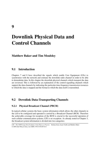


![188 LTE – THE UMTS LONG TERM EVOLUTION
Table 9.1 Key simulation parameters for Figure 9.4.
Parameter Value
Carrier frequency 2 GHz
Bandwidth 5 MHz
Channel model Urban micro, 3 km/h
Total eNodeB transmit power 43 dBm
VoIP model 12.2 kbps; voice activity factor 0.43
Modulation and coding scheme Fixed: QPSK, code rate 2/3
Satisfaction criterion 98% packets within 50 ms
PDCCH in the same way as for other PDSCH data, except that the identity indicated on
the PDCCH is not the identity of a specific UE but is, rather, a designated broadcast identity
known as the System Information Radio Network Temporary Identifier (SI-RNTI), which is
fixed in the specifications (see Section 7.1 of [1]) and therefore known a priori to all UEs.
Some constraints exist as to which subframes may be used for particular system information
messages on the PDSCH; these are explained in Section 3.2.2.
Another special use of the PDSCH is for paging, as no separate physical channel is
provided in LTE for this purpose. In previous systems such as WCDMA, a special ‘Paging
Indicator Channel’ was provided, which was specially designed to enable the UE to wake
up its receiver periodically for a very short period of time, in order to minimize the impact
on battery life; on detecting a paging indicator (typically for a group of UEs), the UE would
then keep its receiver switched on to receive a longer message indicating the exact identity
of the UE being paged. By contrast, in LTE the PDCCH signalling is already very short in
duration, and therefore the impact on UE battery life of monitoring the PDCCH from time
to time is low. Therefore the normal PDCCH signalling can be used to carry the equivalent
of a paging indicator, with the detailed paging information being carried on the PDSCH in a
resource block indicated by the PDCCH. In a similar way to broadcast data, paging indicators
on the PDCCH use a single fixed identifier, in this case the Paging RNTI (P-RNTI). Rather
than providing different paging identifiers for different groups of UEs, different UEs monitor
different subframes for their paging messages, as described in Section 3.4.
9.2.3 Physical Multicast Channel (PMCH)
Although Multimedia Broadcast and Multicast Services (MBMS) are not included in the first
release of the LTE specifications, nonetheless the physical layer structure to support MBMS
is defined ready for deployment in a later release. All UEs must be aware of the possible
existence of MBMS transmissions at the physical layer, in order to enable such transmissions
to be introduced later in a backward-compatible way.
The basic structure of the Physical Multicast Channel (PMCH) is very similar to the
PDSCH. However, the PMCH is designed for ‘single-frequency network’ operation, whereby
multiple cells transmit the same modulated symbols with very tight time-synchronization,
ideally so that the signals from different cells are received within the duration of the cyclic
prefix. This is known as MBSFN (MBMS Single Frequency Network) operation, and is
discussed in more detail in Section 14.3. As the channel in MBSFN operation is in effect](https://image.slidesharecdn.com/ltefromtheorytopractise-240124145854-b0067765/85/LTE_from_Theory_to_Practise-pdf-216-320.jpg)


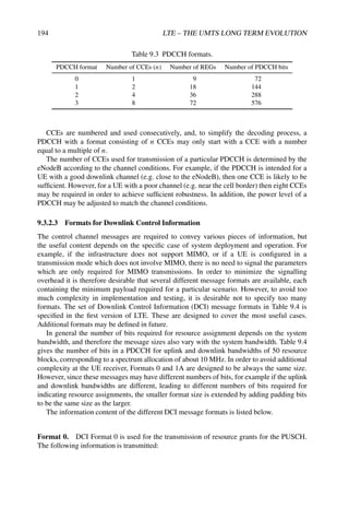


![202 LTE – THE UMTS LONG TERM EVOLUTION
Table 9.6 RBG size for Type 0 resource allocation.
Downlink bandwidth NDL
RB RBG size (P)
0 ≤ 10 1
11–26 2
27–63 3
64–110 4
PRB
1
PRB
2
PRB
3
RBG1
PRB
4
PRB
5
PRB
6
PRB
7
PRB
8
PRB
9
PRB
10
PRB
11
PRB
12
PRB
13
PRB
14
PRB
15
PRB
16
PRB
17
PRB
18
PRB
19
PRB
20
PRB
21
PRB
22
PRB
23
PRB
24
PRB
25
RBG2 RBG3 RBG4 RBG5 RBG6 RBG7 RBG8 RBG9 RBG10 RBG11 RBG12 RBG13
frequency
Figure 9.10 PRB addressed by a bitmap Type 0, each bit addressing a complete RBG.
smaller than for Type 0, since some bits are used to indicate the subset of the RBG which is
addressed, and a shift in the position of the bitmap. The total number of bits (including these
additional flags) is the same as for Type 0. An example for the case of NDL
RB = 25, NRBG = 11
and P = 2 is shown in Figure 9.11. One bit is used for subset selection and another bit to
indicate the shift.
The motivation for providing this method of resource allocation is flexibility in spreading
the resources across the frequency domain to exploit frequency diversity.
Resource allocation Type 2. In resource allocations of Type 2, the resource allocation
information indicates to a scheduled UE either:
• a set of contiguously allocated PRBs, or
• a distributed allocation comprising multiple non-consecutive PRBs (see Section
9.2.2.1).
The distinction between the two allocation methods is made by a 1-bit flag in the resource
allocation message. PRB allocations may vary from a single PRB up to a maximum number
of PRBs spanning the system bandwidth. A Type 2 resource allocation field consists of a
Resource Indication Value (RIV) corresponding to a starting resource block (RBSTART) and
a length in terms of contiguously-allocated resource blocks (LCRBs). The resource indication
value is defined by
if (LCRBs − 1) ≤ NDL
RB /2 then RIV = NDL
RB (LCRBs − 1) + RBSTART
else
RIV = NDL
RB (NDL
RB − LCRBs + 1) + (NDL
RB − 1 − RBSTART)
An example of a method for reversing the mapping to derive the resource allocation from the
RIV can be found in [2].](https://image.slidesharecdn.com/ltefromtheorytopractise-240124145854-b0067765/85/LTE_from_Theory_to_Practise-pdf-230-320.jpg)


![206 LTE – THE UMTS LONG TERM EVOLUTION
References5
[1] 3GPP Technical Specification 36.321, ‘Multiplexing and Channel Coding (FDD) (Release 8)’,
www.3gpp.org.
[2] NEC, ‘R1-072119: DL Unicast Resource Allocation Signalling’, www.3gpp.org, 3GPP TSG RAN
WG1, meeting 49, Kobe, Japan, May 2007.
5All web sites confirmed 18th December 2008.](https://image.slidesharecdn.com/ltefromtheorytopractise-240124145854-b0067765/85/LTE_from_Theory_to_Practise-pdf-234-320.jpg)


![CHANNEL CODING AND LINK ADAPTATION 209
transmitter should try to match the information data rate for each user to the variations in
received signal quality (see, for example, [1, 2] and references therein). This is commonly
referred to as link adaptation and is typically based on Adaptive Modulation and Coding
(AMC).
The degrees of freedom for the AMC consist of the modulation and coding schemes:
• Modulation Scheme. Low-order modulation (i.e. few data bits per modulated symbol,
e.g. QPSK) is more robust and can tolerate higher levels of interference but provides
a lower transmission bit rate. High-order modulation (i.e. more bits per modulated
symbol, e.g. 64AQM) offers a higher bit rate but is more prone to errors due to its
higher sensitivity to interference, noise and channel estimation errors; it is therefore
useful only when the SINR is sufficiently high.
• Code rate. For a given modulation, the code rate can be chosen depending on the
radio link conditions: a lower code rate can be used in poor channel conditions and a
higher code rate in the case of high SINR. The adaptation of the code rate is achieved
by applying puncturing or repetition to the output of a mother code, as explained in
Section 10.3.2.4.
A key issue in the design of the AMC scheme for LTE was whether all Resource
Blocks (RBs) allocated to one user in a subframe should use the same Modulation and
Coding Scheme (MCS) (see, for example, [3–6]) or whether the MCS should be frequency-
dependent within each subframe. It was shown that in general only a small throughput
improvement arises from a frequency-dependent MCS compared to an RB-common MCS
in the absence of transmission power control, and therefore the additional control signalling
overhead associated with frequency-dependent MCS is not justified. Therefore in LTE the
modulation and channel coding rates are constant over the allocated frequency resources for
a given user, and time-domain channel-dependent scheduling and AMC is supported instead.
In addition, when multiple transport blocks are transmitted to one user in a given subframe
using multistream Multiple-Input Multiple-Output (MIMO) (as discussed in Chapter 11),
each transport block can use an independent MCS.
In LTE the UE can be configured to report CQIs to assist the eNodeB in selecting an
appropriate MCS to use for the downlink transmissions. The CQI reports are derived from the
downlink received signal quality, typically based on measurements of the downlink reference
signals (see Section 8.2). It is important to note that, like HSDPA, the reported CQI is not
a direct indication of SINR in LTE. Instead, the UE reports the highest MCS that it can
decode with a transport block error rate probability not exceeding 10%. Thus the information
received by the eNodeB takes into account the characteristics of the UE’s receiver, and not
just the prevailing radio channel quality. Hence a UE that is designed with advanced signal
processing algorithms (for example, using interference cancellation techniques) can report a
higher channel quality and, depending on the characteristics of the eNodeB’s scheduler, can
receive a higher data rate.
A simple method by which a UE can choose an appropriate CQI value could be based on
a set of Block Error Rate (BLER) thresholds, as illustrated by way of example in Figure 10.1.
The UE would report the CQI value corresponding to the MCS that ensures BLER ≤ 10−1
based on the measured received signal quality.
The list of modulation schemes and code rates which can be signalled by means of a CQI
value is shown in Table 10.1 (from [7]).](https://image.slidesharecdn.com/ltefromtheorytopractise-240124145854-b0067765/85/LTE_from_Theory_to_Practise-pdf-237-320.jpg)


![CHANNEL CODING AND LINK ADAPTATION 213
Table 10.4 Sub-band size k and number of preferred sub-bands (M) versus downlink system
bandwidth for aperiodic CQI reports for UE-selected sub-bands feedback. Reproduced by
permission of © 3GPP.
System bandwidth Sub-band size Number of preferred sub-bands
(RBs) (k RBs) (M)
6–7 (Wideband CQI only) (Wideband CQI only)
8–10 2 1
11–26 2 3
27–63 3 5
64–110 4 6
is the extended binomial coefficient, resulting in a unique label r ∈ {0, . . . ,
N
M − 1}.
Some possible algorithms for deriving the combinatorial index r in the UE and
extracting the information from it in the eNodeB can be found in [8] and [9]
respectively.
The CQI value for the M selected sub-bands for each codeword is encoded differen-
tially using 2-bits relative to its respective wideband CQI as defined by
Differential CQI
= Index for average of M preferred sub-bands − Wideband CQI index
Possible differential CQI values are {≤ +1, +2, +3, ≥ +4}.
10.2.1.2 Periodic CQI Reporting
If the eNodeB wishes to receive periodic reporting of the CQI, the UE will transmit the
reports using the PUCCH.1 Only wideband and UE-selected sub-band feedback is possible
for periodic CQI reporting, for all downlink (PDSCH) transmission modes. As with the
aperiodic CQI reporting, the type of periodic reporting is configured by the eNodeB by
RRC signalling. For the wideband periodic CQI reporting, the period can be configured
to {2, 5, 10, 16, 20, 32, 40, 64, 80, 160} ms or Off (for FDD; see [7] section 7.2.2 for
TDD).
While the wideband feedback mode is similar to that sent via the PUSCH, the ‘UE-
selected sub-band’ CQI using PUCCH is different. In this case, the total number of sub-bands
N is divided into J fractions called bandwidth parts. The value of J depends on the system
bandwidth as summarized in Table 10.5. In case of periodic UE-selected sub-band CQI
reporting, one CQI value is computed and reported for a single selected sub-band from each
bandwidth part, along with the corresponding sub-band index.
1If PUSCH transmission resources are scheduled for the UE in one of the periodic subframes, the periodic CQI
report is sent on the PUCCH instead.](https://image.slidesharecdn.com/ltefromtheorytopractise-240124145854-b0067765/85/LTE_from_Theory_to_Practise-pdf-241-320.jpg)
![214 LTE – THE UMTS LONG TERM EVOLUTION
Table 10.5 Periodic CQI reporting with UE-selected sub-bands: sub-band size (k) and
bandwidth parts (J) versus downlink system bandwidth. Reproduced by permission of
© 3GPP.
System bandwidth Sub-band size Number of bandwidth parts
(RBs) (k RBs) (J)
6–7 (Wideband CQI only) 1
8–10 4 1
11–26 4 2
27–63 6 3
64–110 8 4
10.3 Channel Coding
Channel coding, and in particular the channel decoder, has retained its reputation for being
the dominant source of complexity in the implementation of wireless communications, in
spite of the relatively recent prevalence of advanced antenna techniques with their associated
complexity.
Section 10.3.1 introduces the theory behind the families of channel codes of relevance
to LTE. This is followed in Sections 10.3.2 and 10.3.3 by an explanation of the practical
design and implementation of the channel codes used in LTE for data and control signalling
respectively.
10.3.1 Theoretical Aspects of Channel Coding
The next subsection explains convolutional codes, as not only do they remain relevant for
small data blocks, but also an understanding of them is a prerequisite for understanding turbo
codes. The turbo coding principle and the Soft-Input Soft-Output (SISO) decoding algorithms
are then discussed. The section concludes with a brief introduction to LDPC codes.
10.3.1.1 From Convolutional Codes to Turbo Codes
A convolutional encoder C(k, n, m) is composed of a shift register with m stages. At each
time instant, k information bits enter the shift register and k bits in the last position of the
shift register are dropped. The set of n output bits is a linear combination of the content of the
shift register. The rate of the code is defined as Rc = k/n. Figure 10.2 shows, as example,
the convolutional encoder used in LTE [10] with m = 6, n = 3, k = 1 and rate Rc = 1/3.
The linear combinations are defined via n generator sequences G = [g0, . . . , gn−1] where
g = [g ,0, g ,1, . . . , g ,m].
The generator sequences used in Figure 10.2 are
g0 = [1 0 1 1 0 1 1], g1 = [1 1 1 1 0 0 1], g2 = [1 1 1 0 1 0 1]
or using octal notation
g0 = [133](oct), g1 = [171](oct), g2 = [165](oct)](https://image.slidesharecdn.com/ltefromtheorytopractise-240124145854-b0067765/85/LTE_from_Theory_to_Practise-pdf-242-320.jpg)
![CHANNEL CODING AND LINK ADAPTATION 215
N
F
N
G
N
G
N
G
Figure 10.2 Rate 1/3 convolutional encoder used in LTE with m = 6, n = 3, k = 1 [10].
Reproduced by permission of © 3GPP.
A convolutional encoder can be described by a trellis diagram [11], which is a representation
of a finite state machine including the time dimension.
Consider an input block with L bits encoded with a rate 1/n (i.e. k = 1) convolutional
encoder, resulting in a codeword of length (L + m) × n bits, including m trellis termination
bits (or tail bits) which are inserted at the end of the information block to drive the shift
register contents back to all zeros at the end of the encoding process. Note that using tail bits
is just one possible way of terminating an input sequence. Other trellis termination methods
include simple truncation (i.e. no tail bits appended) and so-called tail-biting [12]. In the
tail-biting approach, the initial and final states of the convolutional encoder are required
to be identical. Usually tail-biting for feed-forward convolutional encoders is achieved by
initializing the shift register contents with the last m information bits in the input block. Tail-
biting encoding facilitates uniform protection of the information bits and suffers no rate-loss
owing to the tail bits. Tail-biting convolutional codes can be decoded using, for example, the
Circular Viterbi Algorithm (CVA) [13,14].
Let the received sequence y be expressed as
y =
!
Ebx + n (10.1)
where
n = [n0, n1, . . . , n , . . . , n(L+m)×(n−1)]
and n ∼ N(0, N0) is the Additive White Gaussian Noise (AWGN), Eb is the energy per bit.
The transmitted codeword is
x = [x0, x1, . . . , x , . . . , xL+m−1]
where x is the convolutional code output sequence at time instant for the input information
bit i , given by x = [x ,0, . . . , x ,n−1] and equivalently
y = [y0, y1, . . . , y , . . . , yL+m−1]
where y = [y ,0, . . . , y ,n−1] is the noisy received version of x. (L + m) is the total trellis
length.
10.3.1.2 Soft-Input Soft-Output (SISO) Decoders
In order to define the performanceof a communication system, the codeword error probability
or bit error probability can be considered. The minimization of the bit error probability is in](https://image.slidesharecdn.com/ltefromtheorytopractise-240124145854-b0067765/85/LTE_from_Theory_to_Practise-pdf-243-320.jpg)
![216 LTE – THE UMTS LONG TERM EVOLUTION
general more complicated and requires the maximization of the a-posteriori bit probability
(MAP symbol-by-symbol). The minimization of the codeword/sequence error probability is
in general easier and is equivalent to the maximization of A Posteriori Probability (APP) for
each codeword; this is expressed by the MAP sequence detection rule, whereby the estimate
x̂ of the transmitted codeword is given by
x̂ = argmax
x
P(x | y) (10.2)
When all codewords are equiprobable, the MAP criterion is equivalent to the Maximum
Likelihood (ML) criterion which selects the codeword that maximizes the probability of the
received sequence y conditioned on the estimated transmitted sequence x, i.e.
x̂ = argmax
x
P(y | x) (10.3)
Maximizing Equation (10.3) is equivalent to maximizing the logarithm of P(y | x), as
log(·) is a monotonically increasing function. This leads to simplified processing.2 The log-
likelihood function for a memoryless channel can be written as
log P(y | x) =
L+m−1
i=0
n−1
j=0
log P(yi,j | xi,j ) (10.4)
For an AWGN channel, the conditional probability in Equation (10.4) is P(yi,j | xi,j ) ∼
N(
√
Ebxi,j , N0), hence
log P(y | x) ∝ yi −
!
Ebxi
2
(10.5)
The maximization of the metric in Equation (10.5) yields a codeword that is closest to
the received sequence in terms of the Euclidean distance [15]. This maximization can be
performed in an efficient manner by operating on the trellis.
As an example, Figure 10.3 shows a simple convolutional code with generator polynomi-
als g0 = [1 0 1] and g1 = [1 1 1] and Figure 10.4 represents the corresponding trellis diagram.
Each edge in the trellis corresponds to a transition from a state s to a state s, which can be
obtained for a particular input information bit. In Figure 10.4 the edges are parametrized with
the notation i /x ,0 x ,1, i.e. the input/output of the convolutional encoder. The shift registers
of the convolutional code are initialized to the all-0 state. In the example, m tail bits are added
at the end, in order to terminate the trellis, hence the final state will again be the all-0.
Let M(yi | xi) =
n−1
j=0 log P(yi,j | xi,j ) denote the branch metric at the ith trellis step
(i.e. the cost of choosing a branch at trellis step i), given by Equation (10.5).
At the th transition in the trellis, a ‘partial path metric’ can be derived, which is the
accumulated cost of following a specific path inside the trellis until the th transition. This
partial path metric can be written as
Ms (y | x) =
i=0
M(yi | xi) = M −1
s (y | x) + M(y | x ) (10.6)
2The processing is simplified because the multiplication operation can be transformed to the simpler addition
operation in the logarithmic domain.](https://image.slidesharecdn.com/ltefromtheorytopractise-240124145854-b0067765/85/LTE_from_Theory_to_Practise-pdf-244-320.jpg)
![CHANNEL CODING AND LINK ADAPTATION 217
Figure 10.3 Rate 1
2 convolutional encoder with m = 2, m = 2, k = 1, corresponding to
generator polynomials g0 = [1 0 1] and g1 = [1 1 1].
Figure 10.4 Trellis corresponding to convolutional code with generator polynomials g0 =
[1 0 1] and g1 = [1 1 1].
The Viterbi Algorithm (VA) [16, 17] is an efficient way of using the trellis to compute the
‘best’ partial path metric at each trellis step by adding, comparing and selecting metrics as
briefly described in the following. For each state s the VA computes the possible partial path
metrics corresponding to all the edges arriving in the state s, and it selects the best partial
metric. In the example in Figure 10.4, at time = 2, there are two possible paths ending, for
example, in the state s = 01. The VA computes
M2
01(y | x) = max{M1
10(y | x) + M(y2 | 01), M1
11(y | x) + M(y2 | 10)}
The transition that yields the best path metric is selected as the survival edge and the other one
is discarded. This is carried on for each state and for = 0, . . . , L + m − 1. At the last stage](https://image.slidesharecdn.com/ltefromtheorytopractise-240124145854-b0067765/85/LTE_from_Theory_to_Practise-pdf-245-320.jpg)
![218 LTE – THE UMTS LONG TERM EVOLUTION
= L + m − 1, the VA selects the best total metric among the different metrics computed
for each state (in the case of trellis terminated convolutional code the last state is known to
be the all-0 state) and it traces back the selected path in the trellis to provide the estimated
input sequence.
Although the original VA outputs a hard-decision estimate of the input sequence, the VA
can be modified to output soft information3 along with the hard-decision estimate of the
input sequence [18]. The reliability of coded or information bits can be obtained via the
computation of the a posteriori probability.
In the following analysis, the convolutional code C(1, n, m) encodes the information bit
i , at time , for = 0, . . . , L + m − 1.
In case of a systematic convolutional code, where the uncoded information bits also appear
unmodified in the coded output,4 the codeword x ∈ C(1, n, m) is characterized by x ,0 = i ,
the systematic bit at time instant .
Assuming BPSK (Binary Phase Shift Keying) modulation (0 → +1, and 1 → −1), the
Log Likelihood Ratio (LLR) of an information symbol (or bit) i is
(i ) = (x ,0) = log
APP(i = 1)
APP(i = −1)
= log
P(i = 1 | y)
P(i = −1 | y)
The decoder can make a decision by comparing (i ) to zero. Thus, the sign of the LLR gives
an estimate of the information bit i (LLR ≥ 0 → 0, and LLR 0 → 1), and the magnitude
indicates the reliability of the estimate of the bit. The LLR can be decomposed as follows:
(i ) ∝ Lch(i ) + La priori(i ) + LExt(i ) (10.7)
where
Lch(i ) =
P(y ,0 | i = 1)
P(y ,0 | i = −1)
(10.8)
is also called the ‘channel observation’. For a BPSK modulated AWGN channel with signal
to noise ratio Eb/N0 it can be shown that Lch(i ) = (4Eb/N0)y ,0.
La priori(i ) = log
P(i = 1)
P(i = −1)
(10.9)
is the a priori information (usually equal to zero because of equiprobability of the information
bits). LExt(i ) is the extrinsic information of the bit i , i.e. the LLR obtained from all the bits
of the convolutional code except the systematic bit corresponding to i . The a posteriori LLR
(i ) in Equation (10.7) can be computed via the BCJR algorithm named after its inventors,
Bahl, Cocke, Jelinek and Raviv [19]. The BCJR algorithm is a SISO decoding algorithm
that uses two Viterbi-like recursions going forwards and backwards in the trellis to compute
Equation (10.7) efficiently. For this reason it is also referred to as a ‘forward-backward’
algorithm. A detailed description of the BCJR algorithm can be found in [19].
In order to explain the BCJR algorithm it is better to write the APP from Equation (10.7)
in terms of the joint probability of a transition in the trellis from the state s at time instant ,
3A soft decision gives additional information about the reliability of the decision [15].
4The equations and rationale given here can be easily generalized to non-systematic convolutional codes.](https://image.slidesharecdn.com/ltefromtheorytopractise-240124145854-b0067765/85/LTE_from_Theory_to_Practise-pdf-246-320.jpg)
![CHANNEL CODING AND LINK ADAPTATION 219
to the state s +1 at time instant + 1,
(i ) = log
S+ P(s = s, s +1 = s, y)
S− P(s = s, s +1 = s, y)
= log
S+ p(s, s, y)
S− p(s, s, y)
(10.10)
where s, s ∈ S are possible states of the convolutional encoder, S+ is the set of ordered pairs
(s, s) such that a transition from state s to state s at time is caused by the input bit i = 0.
Similarly, S− is the set of transitions caused by i = 1. The probability p(s, s, y) can be
decomposed as follows:
p(s
, s, y) = p(s
, yt )p(s, y | s
)p(yt | s) (10.11)
where yt
= [y0, . . . , y −1] and yt
= [y , . . . , yL+m−1].
By defining
α (s
)
= p(s
, yt ) (10.12)
β +1(s
)
= p(yt | s) (10.13)
γ (s
, s)
= p(s, y | s
) (10.14)
the APP in Equation (10.10) takes the usual form [19], i.e.
(i ) = log
S+ α (s)γ (s, s)β +1(s)
S− α (s)γ (s, s)β +1(s)
(10.15)
The probability α (s) is computed iteratively in a forward recursion
α +1(s) =
s∈S
α (s
)γ (s
, s) (10.16)
with initial condition α0(0) = 1, α0(s) = 0 for s = 0, assuming that the initial state of the
encoder is 0. Similarly, the probability β (s) is computed via a backward recursion
β (s
) =
s∈S
β +1(s)γ (s
, s) (10.17)
with initial condition βL+m−1(0) = 1, βL+m−1(s) = 0 for s = 0 assuming trellis termination
is employed using tail bits. The transition probability can be computed as
γ (s
, s) = P(y | x )P(i )
The MAP algorithm consists of initializing α0(s), βL+m−1(s), computing the branch metric
γ (s, s), and continuing the forward and backward recursion in Equations (10.16) and
(10.17) to compute the updates of α +1(s) and β (s).
The complexity of the BCJR is approximately three times that of the Viterbi decoder. In
order to reduce the complexity a log-MAP decoder can be considered, where all operations](https://image.slidesharecdn.com/ltefromtheorytopractise-240124145854-b0067765/85/LTE_from_Theory_to_Practise-pdf-247-320.jpg)
![220 LTE – THE UMTS LONG TERM EVOLUTION
D
J
J
D
D
J
E
J
E
E
Figure 10.5 Forward and backward recursions for the BCJR decoding algorithm.
are performed in the logarithmic domain. Thus, the forward and backward recursions
α +1(s), β (s) and γ (s, s) are replaced by α∗
+1(s) = log[α +1(s)], β∗(s) = log[β (s)]
and γ ∗(s, s) = log[γ (s, s)]. This gives advantages for implementation and can be shown
to be numerically more stable. By defining
max∗
(z1, z2)
= log(ez1 + ez2 ) = max(z1, z2) + log(1 + e−|z1−z2|
) (10.18)
it can be shown that the recursion in Equations (10.16) and (10.17) becomes
α∗
+1(s) = log
s∈S
eα∗(s)+γ ∗(s,s)
= max
s∈S
∗
{α∗
(s
) + γ ∗
(s
, s)} (10.19)
with initial condition α∗
0(0) = 0, α∗
0(s) = −∞ for s = 0. Similarly,
β∗
(s
) = max
s∈S
∗
{β∗
+1(s) + γ ∗
(s
, s)} (10.20)
with initial condition β∗
L+m(0) = 0, β∗
L+m(s) = −∞ for s = 0. Figure 10.5 shows a schematic
representation of the forward and backward recursion.
The APP in Equation (10.15) becomes
(i ) = max
(s,s)∈S+
∗
{α∗
(s
) + γ ∗
(s
, s) + β∗
+1(s)}
− max
(s,s)∈S−
∗
{α∗
(s
) + γ ∗
(s
, s) + β∗
+1(s)} (10.21)
In order to reduce the complexity further, the max-log-MAP approximation can be used,
where the max∗ = log(ex + ey) is approximated by max(x, y). The advantage is that the
algorithm is simpler and faster, with the complexity of the forward and backward passes
being equivalent to a Viterbi decoder. The drawback is the loss of accuracy arising from the
approximation.](https://image.slidesharecdn.com/ltefromtheorytopractise-240124145854-b0067765/85/LTE_from_Theory_to_Practise-pdf-248-320.jpg)
![CHANNEL CODING AND LINK ADAPTATION 221
/
Figure 10.6 Schematic view of the SISO decoder.
Figure 10.6 gives a schematic view of the input and output of a SISO decoder. The two
soft inputs are the channel likelihood on coded or information bits, the channel observations
(Lch(xi )) and the a priori probabilities (La priori(i )). The soft outputs are the a posteriori
LLRs for the information (and/or coded) bits ((i )) computed via the BCJR (full MAP,
log-MAP or max-log-MAP) algorithm introduced above and the extrinsic LLRs (LExt(i ))
obtained by using Equation (10.7).
Convolutional codes are the most widely used family of error correcting codes owing to
their reasonably good performance and the possibility for extremely fast decoders based on
the VA, as well as their flexibility in supporting variable input codeword sizes. However, it
is well known that there remains a significant gap between the performance of convolutional
codes and the theoretical limits set by Shannon.5 In the early 1990s, an encoding and
decoding algorithm based on convolutional codes was proposed [20], which exhibited
performance within a few tenths of a deciBel from the Shannon limit – the turbo code family
was born. Immediately after turbo codes were discovered, Low-Density Parity Check (LDPC)
codes [23–25] that also provided near-Shannon limit performance were also rediscovered.
10.3.1.3 Turbo Codes
Berrou, Glavieux and Thitimajasimha introduced turbo codes and the concept of iterative
decoding to achieve near-Shannon limit performance [20, 26]. Some of the reasoning
regarding probabilistic processing can be found in [18,27], as recognized by Berrou in [28].
A turbo encoder consists of a concatenation of two convolutional encoders linked by an
interleaver. For instance, the turbo encoder adopted in UMTS and LTE [10] is schematically
represented in Figure 10.7 with two identical convolutional codes with generator polynomial
given by G = [1, g0/g1] where g0 = [1011] and g1 = [1101]. Thus, a turbo code encodes
the input block twice (with and without interleaving) to generate two distinct set of parity
bits. Each constituent encoder may be terminated to the all zero state by using tail bits. The
nominal code rate of the turbo code shown in Figure 10.7 is 1/3.
Like convolutional codes, the optimal decoder for turbo codes would ideally be the MAP
or ML decoder. However the number of states in the trellis of a turbo code is significantly
larger due to the interleaver , thus making a true ML or MAP decoder intractable (except for
5‘Shannon’s theorem’, otherwise known as the ‘noisy-channel coding theorem’, states that if and only if the
information rate is less than the channel capacity, then there exists a coding-decoding scheme with vanishing error
probability when the code’s block length tends to infinity [21,22].](https://image.slidesharecdn.com/ltefromtheorytopractise-240124145854-b0067765/85/LTE_from_Theory_to_Practise-pdf-249-320.jpg)
![222 LTE – THE UMTS LONG TERM EVOLUTION
3
Figure 10.7 Schematic view of parallel turbo code used in LTE and UMTS [10]. Reproduced
by permission of © 3GPP.
3
3
Figure 10.8 Schematic turbo decoder representation.
trivial block sizes). Therefore, Berrou et al. [26] proposed the principle of iterative decoding.
This is based on a suboptimal approach using a separate optimal decoder for each constituent
convolutional coder, with the two constituent decoders iteratively exchanging information
via a (de)interleaver. The classical decoding structure is shown in Figure 10.8.](https://image.slidesharecdn.com/ltefromtheorytopractise-240124145854-b0067765/85/LTE_from_Theory_to_Practise-pdf-250-320.jpg)
![CHANNEL CODING AND LINK ADAPTATION 223
The SISO decoder for each constituent convolutional code can be implemented via the
BCJR algorithm (or the MAP algorithm) which was briefly described in the previous section.
The SISO decoder outputs an a posteriori LLR value for each information bit, and this can be
used to obtain a hard decision estimate as well as a reliability estimate. In addition, the SISO
decoder generates extrinsic LLRs for each information bit that is utilized by the other decoder
as a priori information after suitable (de)interleaving. Thus the two decoders cooperate by
iteratively exchanging the extrinsic information via the (de)interleaver. After a certain number
of iterations, the a posteriori LLR output can be used to obtain final hard decision estimates
of the information bits.
10.3.1.4 Low-Density Parity-Check (LDPC) Codes
Low-Density Parity-Check (LDPC) codes were first studied by Gallager in his doctoral
thesis [23] and extensively analysed by many researchers in recent years. LDPC codes are
linear parity-check codes with a parity-check equation given by HcT = 0, where H is the
(n − k) × n parity-check matrix of the code C(k, n) and c is a length-n valid codeword
belonging to the code C. Similarly to turbo codes, ML decoding for LDPC codes becomes
too complex as the block size increases. In order to approximate ML decoding, Gallager
in [23] introduced an iterative decoding technique which can be considered as the forerunner
of message-passing algorithms [24,29], which lead to an efficient LDPC decoding algorithm
with a complexity which is linear with respect to the block size.
The term ‘low-density’ refers to the fact that the parity-check matrix entries are mostly
zeros – in other words, the density of ones is low. The parity-check matrix of an LDPC code
can be represented graphically by a ‘Tanner graph’, in which two types of node, variable and
check, are interconnected. The variable nodes and check nodes correspond to the codeword
bits and the parity-check constraints respectively. A variable node vj is connected to a check
node ci if the corresponding codeword bit participates in the parity-check equation, i.e. if
H(i, j) = 1. Thus, the Tanner graph is an excellent tool by which to visualize the code
constraints and to describe the decoding algorithms. Since an LDPC code has a low density
of ones in H, the number of interconnections in the Tanner graph is small (and typically
linear with respect to the codeword size).
Figure 10.9 shows an example of a Tanner graph of a (10, 5) code with the parity-check
matrix H given in Equation (10.22),6
H =
1 1 1 1 0 1 1 0 0 0
0 0 1 1 1 1 1 1 0 0
0 1 0 1 0 1 0 1 1 1
1 0 1 0 1 0 0 1 1 1
1 1 0 0 1 0 1 0 1 1
(10.22)
As mentioned above, LDPC codes are decoded using message passing algorithms such as
Belief Propagation (BP) or the Sum-Product Algorithm (SPA). The idea of BP is to calculate
approximate marginal a posteriori LLRs by applying Bayes’ rule locally and iteratively at the
nodes in the Tanner graph. The variable nodes and check nodes in the Tanner graph exchange
LLR messages along their interconnections in an iterative fashion, thus cooperating with each
other in the decoding process. Only extrinsic messages are passed along the interconnections
6This particular matrix is not actually ‘low density’, but it is used for the sake of illustration.](https://image.slidesharecdn.com/ltefromtheorytopractise-240124145854-b0067765/85/LTE_from_Theory_to_Practise-pdf-251-320.jpg)
![224 LTE – THE UMTS LONG TERM EVOLUTION
v1
v2
v3
v4
v5
v6
v7
v8
v9
v10
c1
c2
c3
c4
c5
Figure 10.9 A Tanner graph representing the parity-check matrix of a (3, 6)-regular LDPC
code C(10, 5).
to ensure that a node does not receive repeats of information which it already possesses,
analogous to the exchange of extrinsic information in turbo decoding.
It is important to note that the number of operations per iteration in the BP algorithm is
linear with respect to the number of message nodes. However, the BP decoding of LDPC
codes is also suboptimal, like the turbo codes, owing to the cycles in the Tanner graph.7
Cycles increase the dependencies between the extrinsic messages being received at each
node during the iterative process. However, the performance loss can be limited by avoiding
excessive occurrences of short cycles. After a certain number of iterations, the a posteriori
LLRs for the codeword bits are computed to obtain the final hard decision estimates.
Typically, more iterations are required for LDPC codes to converge than are required for
turbo codes. In practice, a variation of BP known as the Layered BP (LBP) algorithm is
preferred, as it requires half as many iterations as the conventional BP algorithm [30].
So far, LDPC codes have been discussed from a decoding perspective, i.e. as the null space
of a sparse matrix. A straightforward encoding algorithm based on the parity-check matrix
7A cycle of length P in a Tanner graph is a set of P connected edges that starts and ends at the same node.
A cycle verifies the condition that no nodes (except the initial and final node) appear more than once.](https://image.slidesharecdn.com/ltefromtheorytopractise-240124145854-b0067765/85/LTE_from_Theory_to_Practise-pdf-252-320.jpg)
![CHANNEL CODING AND LINK ADAPTATION 225
would require a number of operations that is proportional to the square of the codeword size.
However, there exist several LDPC code designs (including those used in the IEEE 802.16e,
IEEE 802.11n and DVB-S2 standards) which have linear encoding complexity and extremely
good performance.
In recent years, several analytical tools have been developed to understand and design
LDPC codes. Density evolution (or threshold analysis) [29, 31] is a valuable tool by which
the theoretical performance of an ensemble of LDPC codes using the message passing
decoder can be estimated in a fast and efficient manner. Rather than focusing on a particular
parity-check matrix, density evolution characterizes the performance of an ensemble (or
family) of codes with similar characteristics. For instance, an LDPC ensemble is often
defined by its left and right degree distributions using polynomials λ(x)
=
dv
i=2 λixi−1 and
ρ(x)
=
dc
i=2 ρixi−1, where λi and ρi are the fractions of interconnections in the Tanner
graph connected respectively to variable nodes and check nodes of degree i, dv denotes the
maximum variable node degree and dc is the maximum check node degree. The code rate of
the ensemble is given by
R = 1 −
1
0 ρ(x) dx
1
0 λ(x) dx
It has been shown that for long code lengths (n → ∞) all the randomly-constructed codes
belonging to the same ensemble behave alike (Concentration Theorem [29]). For an LDPC
code ensemble, density evolution characterizes the performance in terms of a threshold value
(typically expressed as a SNR value) above which there exists at least one code in the
ensemble that can achieve arbitrarily small BER [29]. For SNRs above the threshold, the BER
is bounded away from zero for any number of decoder iterations. Given its similarity to the
Shannon-limit, the threshold is sometimes referred to as the ‘capacity’ of LDPC codes under
message passing decoding. Using density evolution to optimize the degree distributions,
several publications have demonstrated LDPC code performance with a few tenths of a
decibel of the Shannon limit [24,32].
The structure of LDPC codes is another important aspect which greatly affects the
encoding and decoding complexity. A randomly-constructed LDPC code has a random
Tanner graph structure and leads to a complicated hardware design. Therefore, practical
LDPC designs such as the 802.16e and 802.11n LDPC codes are often based on structured
LDPC codes to facilitate efficient encoding and decoding. With structured or vectorized
LDPC codes, the parity-check matrices are constructed using submatrices which are all-
zero or circulant (shifted identity matrices), and such codes require substantially lower
encoding/decoding complexity without sacrificing performance. Much literature exists on
this subject, and the interested reader is referred, for example, to [33] and references therein.
10.3.2 Channel Coding for Data Channels in LTE
Turbo codes found a home in UMTS relatively rapidly after their publication in 1993, with
the benefits of their near-Shannon limit performance outweighing the associated costs of
memory and processing requirements. Once the turbo code was defined in UMTS there was
little incentive to reopen the specification as long as it was functional. In fact, the effort
required for the standardization of the turbo codes for UMTS was near-epic: every aspect of](https://image.slidesharecdn.com/ltefromtheorytopractise-240124145854-b0067765/85/LTE_from_Theory_to_Practise-pdf-253-320.jpg)
![226 LTE – THE UMTS LONG TERM EVOLUTION
Table 10.6 Major features of UMTS and LTE channel coding schemes.
Channel coding UMTS LTE
Constituent code Tailed, eight states, R = 1/3 Same
mother code
Turbo interleaver Row/column permutation Contention-free quadratic
permutation polynomial (QPP)
interleaver
Rate matching Performed on concatenated
code blocks
Virtual Circular Buffer (CB) rate
matching, performed per code block
Hybrid ARQ Redundancy Versions (RVs)
defined, Chase operation
allowed
RVs defined on virtual CB, Chase
operation allowed
Control channel 256-state tailed
convolutional code
64-state tail-biting convolutional
code, CB rate matching
Per code block operations Turbo coding only CRC attachment, turbo coding, rate
matching, modulation mapping
the detailed design became a protracted engagement in meeting rooms around the world. The
result of the effort, while not exactly beautiful, contained a certain appeal.
Therefore, although in UMTS Releases 5, 6 and 7 the core turbo code was not
touched, it was enhanced by the ability to select different redundancy versions for HARQ
retransmissions. However the decoder, originally working at 384 kbps, was starting to show
the strain at 10 Mbps. Managing to get the UMTS decoder to run at ever higher data rates was
viewed as a publication-worthy achievement [34]. As the LTE effort began in 3GPP, every
aspect of system design was under scrutiny in the effort to lay out a viable roadmap for the
next generations of cellular devices; with data rates of 100 Mbps to 300 Mbps in view, and
possibly greater beyond Release 8, the UMTS turbo code needed to be re-examined.
Sections 10.3.2.1 and 10.3.2.2 explain the eventual decision not to use LDPC codes
for LTE, while replacing the turbo interleaver with a ‘contention-free’ interleaver. The
subsequent sections explain the specific differences between LTE channel coding and UMTS
as summarized in Table 10.6.
10.3.2.1 The Lure of the LDPC Code
The draw of LDPC codes is clear: performance almost up to the Shannon limit, with promises
of up to eight times less complexity than turbo codes [35]. LDPC codes had also recently
been standardized as an option in IEEE 802.16-2005. The complexity angle is all-important
in LTE, provided that the excellent performance of the turbo code is maintained. However,
LDPC proposals put forward for LTE claimed widely varying complexity benefits, from no
benefits to 2.4 times [36] up to 7.35 times [37]. In fact, it turns out that the complexity benefit
is code-rate dependent, with roughly a factor of two reduction in the operations count at code
rate 1/2 [38]. This comparison assumes that the LDPC code is decoded with the Layered](https://image.slidesharecdn.com/ltefromtheorytopractise-240124145854-b0067765/85/LTE_from_Theory_to_Practise-pdf-254-320.jpg)
![CHANNEL CODING AND LINK ADAPTATION 227
Belief Propagation (LBP) decoder [30] while the turbo code is decoded with a log-MAP
decoder.
On operations count alone, LDPC would be the choice for LTE. However, at least three
factors curbed enthusiasm for LDPC. First, LDPC decoders have significant implementation
complexity for memory and routing, which makes simple operation counts unrepresentative.
Second, HARQ is a key feature introduced in HSPA, and the incremental redundancy
performance of LDPC is unclear. Finally, turbo codes were already standardized in UMTS,
and a similar lengthy standardization process was undesired when perhaps a relatively simple
enhancement to the known turbo code would suffice. It was therefore decided to keep the
same turbo code constituent encoders as in the UMTS turbo code, including the tailing
method, but to enhance it using a new contention-free interleaver that enables efficient
decoding at the high data rates targeted for LTE. Table 10.7 gives a comparison of some
of the features of turbo and LDPC codes which will be explained in the following sections.
10.3.2.2 Contention-Free Turbo Decoding
The key to high data-rate turbo decoding is to parallelize the turbo decoder efficiently while
maintaining excellent performance. The classical turbo decoder has two MAP decoders
(usually realized via a single hardware instantiation) that exchange extrinsic information in an
iterative fashion between the two component codes, as described in Section 10.3.1. Thus, the
first consideration is whether the parallelism is applied internally to the MAP decoder (single
codeword parallelization) or externally by employing multiple turbo decoders (multiple
codeword parallelizations with no exchange of extrinsic information between codewords).
If external parallelism is adopted, an input block may be split into X pieces, resulting in
X codewords, and the increase in processing speed is obtained by operating up to X turbo
decoders in parallel on the X codewords. In this case, in addition to a performance loss due
to the smaller turbo interleaver size in each codeword, extra cost is incurred for memory and
ancillary gate counts for forward-backward decoders. For this reason, one larger codeword
with internal MAP parallelization is preferred. With one larger codeword, the MAP algorithm
is run in parallel on each of the X pieces and the pieces can exchange extrinsic information,
thus benefiting from the coding gains due to the large interleaver size. Connecting the pieces
is most easily done with forward and backward state initialization based on the output of the
previous iterations, although training within adjacent pieces during the current iteration is
also possible [39]. As long as the size of each piece is large enough (e.g. 32 bits or greater),
performance is essentially unaffected by the parallel processing.
While it is clear that the MAP algorithm can be parallelized, the MAP is not the entire
turbo decoder. Efficient handling of the extrinsic message exchange (i.e. the (de)interleaving
operation) is required as well. Since multiple MAP processors operate in parallel, multiple
extrinsic values need to be read from or written to the memories concurrently. The memory
accesses depend on the interleaver structure.
The existing UMTS interleaver has a problem with memory access contentions. Con-
tentions result in having to read or write from/to the same memory at the same time (as
shown in Figure 10.10).
Contention resolution is possible (see, e.g., [40] and [41]), but at a cost of extra
hardware, and the resolution time (cycles) may vary for every supported interleaver size.](https://image.slidesharecdn.com/ltefromtheorytopractise-240124145854-b0067765/85/LTE_from_Theory_to_Practise-pdf-255-320.jpg)
![228 LTE – THE UMTS LONG TERM EVOLUTION
Table 10.7 Comparison of turbo and LDPC codes.
Turbo codes LDPC codes
Standards UMTS, LTE, IEEE 802.16e,
WiMAX IEEE802.11n
DVB-S2
Encoding Linear time Linear time with
certain designs (802.16e/802.11n)
Decoding log-MAP, and variants Scheduling: Layered Belief Propagation,
turbo-decoding
Node processing: Min-Sum,
normalized Min-Sum
Main decoding Computationally intensive Memory intensive
concern (more operations) (more memory),
routing network
Throughput No inherent parallelism. Inherently parallelizable.
Parallelism obtained Structured LDPC codes
via contention-free interleaver for flexible design
Performance Comparable for information Can be slightly better than
block sizes 103–104. turbo codes at large block
Slightly better than LDPC lengths (104 or larger,
at small block sizes. iterative decoding threshold analysis.
Four to eight iterations Very low error floor
on average (e.g. at BLER around 10−7).
10 to 15 iterations on average
HARQ Simple for both Chase and IR Simple for Chase.
(via mother code puncturing) IR possible using model matrix
extension or puncturing
from a mother code
Complexity comparison Slightly larger operations count Slightly smaller operations count
(operations count) than LDPC at high code rates than turbo at high code rates
Complex memory management may also be used as contention resolution for any arbitrary
interleaver [42].
A new, Contention-Free (CF) interleaver solves the problem by ensuring that no con-
tentions occur in the first place. An interleaver π(i), 0 ≤ i K, is said to be contention-
free for a window size W when it satisfies the following for both interleaver ψ = π and
deinterleaver ψ = π−1 [43]:
#
ψ(u1W + ν)
W
$
=
#
ψ(u2W + ν)
W
$
(10.23)
where 0 ≤ νW, u1 ≥ 0, u2 M for all u1 = u2. The terms on both sides of Equation (10.23)
are the memory bank indices that are accessed by the M processors on the vth step. Inequality](https://image.slidesharecdn.com/ltefromtheorytopractise-240124145854-b0067765/85/LTE_from_Theory_to_Practise-pdf-256-320.jpg)
![CHANNEL CODING AND LINK ADAPTATION 229
window 0
W
W
window 0
window 1
window 1
window 2
window 2
window M 1
window M 1
2
W
+
(
M
1
)
W
Processors
Memory
Banks
Figure 10.10 Illustration of a memory access contention in window 1 due to concurrent
access by Processors 0 and 2.
(10.23) requires that for any given position v of each window, the memory banks accessed
be unique between any two windows, thus eliminating access contentions. For significant
hardware savings, instead of using M physically-separate memories, it is better to use a single
physical memory and fetch/store M values on each cycle from a single address. This requires
the CF interleaver also to satisfy a vectorized decoding property where the intra-window
permutation is the same for each window:
π(uW + ν) mod W = π(ν) mod W (10.24)
for all 1 ≤ u M and 0 ≤ ν W.
Performance, implementation complexity and flexibility are concerns. However, even a
simple CF interleaver composed of look-up tables (for each block size) and a bit-reversal
permutation [44] can be shown to have excellent performance. In terms of flexibility, a
maximally contention-free interleaver can have a parallelism order (number of windows)
that is any factor of the block size. A variety of possible parallelism factors provides freedom
for each individual manufacturer to select the degree of parallelism based on the target data
rates for different UE categories.
After consideration of performance, available flexible classes of CF interleavers and
complexity benefits, a new contention-free interleaver was selected for LTE.
10.3.2.3 The LTE Contention-Free Interleaver
The main choices for the CF interleaver included Almost Regular Permutation (ARP) [45]
and Quadratic Permutation Polynomial (QPP) [46] interleavers. The ARP and QPP inter-
leavers share many similarities and they are both suitable for LTE turbo coding, offering
flexible parallelism orders for each block size, low-complexity implementation, and excellent
performance. A detailed overview of ARP and QPP proposals for LTE (and their comparison
with the UMTS Release-99 turbo interleaver) is given in reference [47]. Of these two closely
competing designs, the QPP interleaver was selected for LTE as it provides more parallelism
factors M, and requires less storage, thus making it better-suited to high data rates.
For an information block size K, a QPP interleaver is defined by the following polynomial:
π(i) = (f1i + f2i2
) mod K (10.25)](https://image.slidesharecdn.com/ltefromtheorytopractise-240124145854-b0067765/85/LTE_from_Theory_to_Practise-pdf-257-320.jpg)
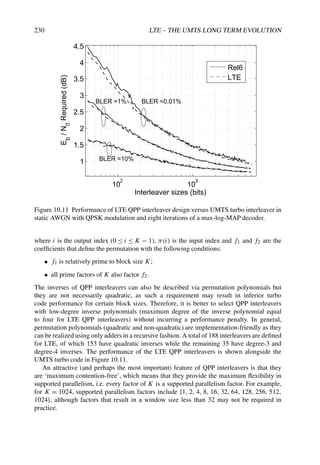
![CHANNEL CODING AND LINK ADAPTATION 231
The QPP interleavers also have the ‘even-even’ property whereby even and odd indices
in the input are mapped to even and odd indices respectively in the output; this enables
the encoder and decoder to process two information bits per clock cycle, facilitating radix-
4 implementations (i.e. all log-MAP decoding operations can process two bits at a time,
including forward/backward recursions, extrinsic LLR generation and memory read/write).
One key impact of the decision to use a CF interleaver is that not all input block sizes are
natively supported. As the amounts of parallelism depend on the factorization of the block
size, certain block sizes (e.g. prime sizes) are not natively supportable by the turbo code.
Since the input can be any size, filler bits are used whenever necessary to pad the input to the
nearest QPP interleaver size. The QPP sizes are selected such that:
• The number of interleavers is limited (fewer interleavers implies more filler bits).
• The fraction of filler bits is roughly the same as the block size increases (spacing
increases as block size increases).
• Multiple parallelism values are available (block sizes are spaced an integer number of
bytes apart).
For performance within approximately 0.1 dB of the baseline UMTS interleaver, as few as 45
interleaver sizes [48] are feasible, although the percentage of filler bits may be high (nearly
12%). For LTE, the following 188 byte-aligned interleaver sizes spaced in a semi-log manner
were selected with approximately 3% filler bits [10]:
K =
40 + 8t if 0 ≤ t ≤ 59 (40–512 in steps of 8 bits)
512 + 16t if 0 t ≤ 32 (528–1024 in steps of 16 bits)
1024 + 32t if 0 t ≤ 32 (1056–2048 in steps of 32 bits)
2048 + 64t if 0 t ≤ 64 (2112–6144 in steps of 64 bits)
(10.26)
The maximum turbo interleaver size was also increased from 5114 in UMTS to 6144 in LTE,
such that a 1500 byte TCP/IP packet would be segmented into only two segments rather than
three, thereby minimizing potential segmentation penalty and (marginally) increasing turbo
interleaver gain.
10.3.2.4 Rate-Matching
The Rate-Matching (RM) algorithm selects bits for transmission from the rate 1/3 turbo
coder output via puncturing and/or repetition. Since the number of bits for transmission is
determined based on the available physical resources, the RM should be capable of generating
puncturing patterns for arbitrary rates. Furthermore, the RM should send as many new bits as
possible in retransmissions to maximize the Incremental Redundancy (IR) HARQ gains (see
Section 4.4 for further details about the HARQ protocol).
The main contenders for LTE RM were to use the same (or similar) algorithm as HSPA,
or to use Circular Buffer (CB) RM as in CDMA2000 1xEV and WiMAX. The primary
advantage of the HSPA RM is that while it appears complex, it has been well studied and
is well understood. However, a key drawback is that there are some severe performance
degradations at higher code rates, especially near code rates 0.78 and 0.88 [49].](https://image.slidesharecdn.com/ltefromtheorytopractise-240124145854-b0067765/85/LTE_from_Theory_to_Practise-pdf-259-320.jpg)
![232 LTE – THE UMTS LONG TERM EVOLUTION
Subblock interleaver 0 Subblock interleaver 1 Subblock interleaver 2
Figure 10.12 Rate-matching algorithm based on the CB. RV = 0 starts at an offset relative
to the beginning of the CB to enable systematic bit puncturing on the first transmission.
Therefore, circular buffer RM was selected for LTE as it generates puncturing patterns
simply and flexibly for any arbitrary code rate, with excellent performance.
In the CB approach, as shown in Figure 10.12, each of the three output streams of the turbo
coder (systematic part, parity0, and parity1) is rearranged with its own interleaver (called a
sub-block interleaver). In LTE the 12 tail bits are distributed equally into the three streams
as well, resulting in the sub-block size Ks = K + 4, where K is the QPP interleaver size.
Then, an output buffer is formed by concatenating the rearranged systematic bits with the
interlacing of the two rearranged parity streams. For any desired code rate, the coded bits for
transmission are simply read out serially from a certain starting point in the buffer, wrapping
around to the beginning of the buffer if the end of the buffer is reached.
A Redundancy Version (RV) specifies a starting point in the circular buffer to start reading
out bits. Different RVs are specified by defining different starting points to enable HARQ
operation. Usually RV = 0 is selected for the initial transmission to send as many systematic
bits as possible. The scheduler can choose different RVs on transmissions of the same packet
to support both IR and Chase combining HARQ.
The turbo code tail bits are uniformly distributed into the three streams, with all streams
the same size. Each sub-block interleaver is based on the traditional row-column interleaver
with 32 columns (for all block size), and a simple length-32 intra-column permutation.
• The bits of each stream are written row-by-row into a matrix with 32 columns (number
of rows determined by the stream size), with dummy bits padded to the front of each
stream to completely fill the matrix.
• A length-32 column permutation is applied and the bits are read out column-by-column
to form the output of the sub-block interleaver,
[0, 16, 8, 24, 4, 20, 12, 28, 2, 18, 10, 26, 6, 22, 14, 30, 1, 17, 9, 25, 5, 21, 13, 29, 3, 19, 11, 27, 7, 23, 15, 31]](https://image.slidesharecdn.com/ltefromtheorytopractise-240124145854-b0067765/85/LTE_from_Theory_to_Practise-pdf-260-320.jpg)
![CHANNEL CODING AND LINK ADAPTATION 233
0 1 2 ………...
Nr
RV=3
RV=0 RV=1 RV=2
Figure 10.13 Two-dimensional visualization of the VCB. The starting points for the four
RVs are the top of the selected columns.
This sub-block interleaver has the property that it naturally first puts all the even indices
and then all the odd indices into the rearranged sub-block.
Given the even-even property of the QPP permutations and the above property of the sub-
block interleaver, the sub-block interleaver of the second parity stream is offset by an odd
value δ = 1 to ensure that the odd and even input indices have equal levels of protection. Thus,
for index i, if πsys(i) denotes the permutation of the systematic bit sub-block interleaver, then
the permutation of the two parity sub-block interleavers are πpar0(i) = πsys(i), and πpar1(i) =
(πsys(i) + δ) mod Ks, where Ks is the subblock size. With the offset δ = 1 used in LTE, the
first Ks parity bits in the interlaced parity portion of the circular buffer correspond to the
Ks systematic bits, thus ensuring equal protection to all systematic bits [50]. Moreover, the
offset enables the systematic bit puncturing feature whereby a small percentage of systematic
bits are punctured in an initial transmission to enhance performance at high code rates. With
the offset, RV = 0 results in partially systematic codes that are self-decodable at high coding
rates, i.e. avoiding the ‘catastrophic’ puncturing patterns which have been shown to exist at
some code rates in UMTS.
A two-dimensional interpretation of the circular buffer (with a total of 96 columns) is
shown in Figure 10.13 (where different shadings indicate bits from different streams and
black cells indicate dummy bits). The one-dimensional CB may be formed by reading bits out
column-by-column from the two-dimensional CB. Bits are read column-by-column starting
from a column top RV location, and the dummy bits are discarded during the output bit
generation. Although the dummy bits can be discarded during subblock interleaving, in LTE
the dummy bits are kept to allow a simpler implementation.
This leads to the foremost advantage of the LTE CB approach, in that it enables
efficient HARQ operation, because the CB operation can be performed without requiring an
intermediate step of forming any actual physical buffer. In other words, for any combination
of the 188 stream sizes and 4 RV values, the desired codeword bits can be equivalently
obtained directly from the output of the turbo encoder using simple addressing based on
sub-block permutation.
Therefore the term ‘Virtual Circular Buffer’ (VCB) is more appropriate in LTE. The LTE
VCB operation also allows Systematic Bit Puncturing (SBP) by defining RV = 0 to skip the](https://image.slidesharecdn.com/ltefromtheorytopractise-240124145854-b0067765/85/LTE_from_Theory_to_Practise-pdf-261-320.jpg)


![236 LTE – THE UMTS LONG TERM EVOLUTION
Figure 10.16 Flow diagram for turbo coded channels in LTE.
TB sizes is restricted such that the segmentation rule described above always results in a
single QPP size for each segment with no filler bits. It is possible that future releases of LTE
may support additional TB sizes.
Following segmentation, a further 24-bit CRC is attached to each code block if the TB
was split into two or more code blocks. This code-block-level CRC can be utilized to devise
rules for early termination of the turbo decoding iterations to reduce decoding complexity. It
is worth noting that the polynomial used for the code-block-level CRC is different from the
polynomial used for the transport block CRC. This is a deliberate design feature in order to
avoid increasing the probability of failing to detect errors as a result of the use of individual
CRCs per code block; if all the code block CRCs pass, the decoder should still check the
transport block CRC, which, being based on a different polynomial, is likely to detect an
error which was not detected by a code-block CRC.
A major difference between LTE and HSDPA is that in LTE most of the channel coding
operations on the Physical Downlink Shared CHannel (PDSCH) are performed at a code-
block level, whereas in HSDPA only turbo coding is performed at the code block level.
Although in the LTE specifications [10] the code block concatenation for transmission is
done prior to the scrambler and modulation mapper, each code block is associated with a
distinct set of modulation symbols, implying that the scrambling and modulation mapping](https://image.slidesharecdn.com/ltefromtheorytopractise-240124145854-b0067765/85/LTE_from_Theory_to_Practise-pdf-264-320.jpg)
 [561, 753](oct) R = 1/2
R = 1/3 [557, 663, 711](oct) R = 1/3
Normalized decoding 1/2 (assuming two 1
complexity iterations of decoding)
Rate matching Circular buffer Algorithmic calculation of rate-matching pattern
operations may in fact be done individually for each code block, which facilitates an efficient
pipelined implementation.
10.3.3 Coding for Control Channels in LTE
Unlike the data, control information (such as is sent on the Physical Downlink Control
CHannel (PDCCH) and Physical Broadcast CHannel (PBCH)) is coded with a convolutional
code, as the code blocks are significantly smaller and the additional complexity of the turbo
coding operation is therefore not worthwhile.
The PDCCH is especially critical from a decoding complexity point-of-view, since a
UE must decode a large number of potential control channel locations as discussed in
Section 9.3.3.2. Another relevant factor in the code design for the PDCCH and the PBCH
is that they both carry a relatively small number of bits, making the tail bits (which were
inserted in UMTS to reset the state of the decoder and avoid iterative decoding) a more
significant overhead. Therefore, it was decided to adopt a tailbiting convolutional code for
LTE, but, in order to limit the decoding complexity, using a new convolutional code with only
64 states instead of the 256-state convolutional code used in UMTS. These key differences
are summarized in Table 10.8.
The LTE convolutional code, shown in Figure 10.2, offers slightly better performance
for the target information block sizes, as shown in Figure 10.17. The initial value of the
shift register of the encoder is set to the values corresponding to the last six information
bits in the input stream so that the initial and final states of the shift register are the same.
The decoder can utilize a Circular Viterbi Algorithm [14] or MAP algorithm [51], with
decoding complexity approximately twice that of the Viterbi decoder with two iterations
(passes through the trellis). With only a quarter the number of states, the overall complexity
of the LTE convolutional code can therefore be argued to be half that of the HSPA code,
provided that only two iterations are used.
The rate-matching for the convolutional code in LTE uses a similar circular buffer method
as for the turbo code. A 32-column interleaver is used, with no interlacing in the circular
buffer (the three parity streams are concatenated in the circular buffer). This structure gives
good performance at higher code rates as well as lower code rates, and therefore LTE has no
need for an additional (different) R = 1/2 generator polynomial as used in UMTS.](https://image.slidesharecdn.com/ltefromtheorytopractise-240124145854-b0067765/85/LTE_from_Theory_to_Practise-pdf-265-320.jpg)

![CHANNEL CODING AND LINK ADAPTATION 239
References9
[1] A. J. Goldsmith and S. G. Chua, ‘Adaptive Coded Modulation for Fading Channels’. IEEE Trans.
on Communications, Vol. 46, pp. 595–602, May 1998.
[2] J. Hayes, ‘Adaptive feedback communications’. IEEE Trans. on Communication Technologies,
Vol. 16, pp. 15–22, February 1968.
[3] NTT DoCoMo, Fujitsu, Mitsubishi Electric Corporation, NEC, QUALCOMM Europe, Sharp,
and Toshiba Corporation, ‘R1-060039: Adaptive Modulation and Channel Coding Rate Control
for Single-antenna Transmission in Frequency Domain Scheduling in E-UTRA Downlink’,
www.3gpp.org, 3GPP TSG RAN WG1 LTE ad Hoc, Helsinki, Finland, January 2006.
[4] LG Electronics, ‘R1-060051: Link Adaptation in E-UTRA Downlink’, www.3gpp.org, 3GPP
TSG RAN WG1 LTE ad Hoc, Helsinki, Finland, January 2006.
[5] NTT DoCoMo, Fujitsu, Mitsubishi Electric Corporation, NEC, Sharp, and Toshiba Corporation,
‘R1-060040: Adaptive Modulation and Channel Coding Rate Control for MIMO Transmission
with Frequency Domain Scheduling in E-UTRA Downlink’, www.3gpp.org, 3GPP TSG RAN
WG1 LTE ad Hoc, Helsinki, Finland, January 2006.
[6] Samsung, ‘R1-060076: Adaptive Modulation and Channel Coding Rate’, www.3gpp.org, 3GPP
TSG RAN WG1 LTE ad Hoc, Helsinki, Finland, January 2006.
[7] 3GPP Technical Specification 36.213, ‘Physical layer procedures (Release 8)’, www.3gpp.org.
[8] Huawei, ‘R1-080555: Labelling Complexity of UE Selected Subbands on PUSCH’,
www.3gpp.org, 3GPP TSG RAN WG1, meeting 51bis, Sevilla, Spain, January 2008.
[9] Huawei, ‘R1-080182: Labelling of UE-selected Subbands on PUSCH’, www.3gpp.org, 3GPP
TSG RAN WG1, meeting 51bis, Sevilla, Spain, January 2008.
[10] 3GPP Technical Specification 36.212, ‘Multiplexing and Channel Coding (FDD) (Release 8)’,
www.3gpp.org.
[11] J. G. Proakis, Digital Communications. New York: McGraw-Hill, 1995.
[12] J. H. Ma and J. W. Wolf, ‘On Tail-Biting Convolutional Codes’. IEEE Trans. on Communications,
Vol. 34, pp. 104–111, February 1986.
[13] R. V. Cox and C. V. Sundberg, ‘An Efficient Adaptive Circular Viterbi Algorithm for Decoding
Generalized Tailbiting Convolutional Codes’. IEEE Trans. on Vehicular Technology, Vol. 43,
pp. 57–68, February 1994.
[14] H. Ma and W. J. Wolf, ‘On Tail-biting Convolutional Codes’. IEEE Trans. on Communications,
Vol. 34, pp. 104–111, February 1986.
[15] S. Lin and D. J. Costello, Error and Control Coding: Fundamentals and Applications. Second
Edition, Prentice Hall: Englewood Cliffs, NJ, 2004.
[16] A. J. Viterbi, ‘Error Bounds for Convolutional Codes and an Asymptotically Optimum Decoding
Algorithm’. IEEE Trans. on Information Theory, Vol. 13, pp. 260–269, April 1967.
[17] G. D. Forney Jr., ‘The Viterbi Algorithm’, in Proc. of the IEEE, March 1973.
[18] J. Haguenauer and P. Hoeher, ‘A Viterbi algorithm with soft-decision outputs and its applications’,
in Proc. of IEEE Globecom, Dallas, TX, 1989.
[19] L. R. Bahl, J. Cocke, F. Jelinek and J. Raviv, ‘Optimal Decoding of Linear Codes for Minimizing
Symbol Error Rate’. IEEE Trans. on Information Theory, Vol. 20, pp. 284–287, March 1974.
[20] C. Berrou and A. Glavieux, ‘Near Optimum Error Correcting Coding and Decoding: Turbo-
codes’. IEEE Trans. on Communications, Vol. 44, pp. 1261–1271, October 1996.
9All web sites confirmed 18th December 2008.](https://image.slidesharecdn.com/ltefromtheorytopractise-240124145854-b0067765/85/LTE_from_Theory_to_Practise-pdf-267-320.jpg)
![240 LTE – THE UMTS LONG TERM EVOLUTION
[21] C. E. Shannon, ‘Communication in the Presence of Noise’, in Proc. IRE, Vol. 37, pp. 10–21,
January 1949.
[22] C. E. Shannon, A Mathematical Theory of Communication. Urbana, IL: University of Illinois
Press, 1998.
[23] R. G. Gallager, ‘Low-Density Parity-Check Codes’. Ph.D. Thesis, Cambridge, MA: MIT Press,
1963.
[24] S. Y. Chung, ‘On the Construction of Some Capacity-Approaching Coding Scheme’. Ph.D.
Thesis, Massachusetts Institute of Technology, September 2000.
[25] D. J. C. MacKay and R. M. Neal, ‘Near Shannon Limit Performance of Low Density Parity Check
Codes’. IEEE Electronics Letters, Vol. 32, pp. 1645–1646, August 1996.
[26] C. Berrou, P. Glavieux and A. Thitimajshima, ‘Near Shannon Limit Error-correcting Coding and
Decoding’, in Proc. IEEE International Conference on Communications, Geneva, Switzerland,
1993.
[27] G. Battail, ‘Coding for the Gaussian Channel: the Promise of Weighted-Output Decoding’.
International Journal of Satellite Communications, Vol. 7, pp. 183–192, 1989.
[28] C. Berrou, ‘The Ten-Year Old Turbo Codes are Entering into Service’. IEEE Communication
Magazine, Vol. 41, no. 8, 2003.
[29] T. J. Richardson and R. L Urbanke, ‘The Capacity of Low-density Parity-check Codes Under
Message-passing Decoding’. IEEE Trans. on Information Theory, Vol. 47, pp. 599–618, February
2001.
[30] M. M. Mansour and N. Shanbhag, ‘High-throughput LDPC Decoders’. IEEE Trans. on Very Large
Scale Integration (VLSI) Systems, Vol. 11, pp. 976–996, October 2003.
[31] T. J. Richardson, M. A Shokrollahi and R. L Urbanke, ‘Design of Capacity-approaching Irregular
Low-density Parity-check Codes’. IEEE Trans. on Information Theory, Vol. 47, pp. 619–637,
February 2001.
[32] S-Y. Chung, G. D., Jr. Forney, T. J. Richardson and R. Urbanke, ‘On the Design of Low-density
Parity-check Codes within 0.0045 dB of the Shannon Limit’. IEEE Communication Letters,
Vol. 5, pp. 58–60, February 2001.
[33] J. Chen, R. M. Tanner, J. Zhang and M. P. C Fossorier, ‘Construction of Irregular LDPC Codes
by Quasi-Cyclic Extension’. IEEE Trans. on Information Theory, Vol. 53, pp. 1479–1483, 2007.
[34] M. Bickerstaff, L. Davis, C. Thomas, D. Garrett and C. Nicol, ‘A 24 Mb/s Radix-4 LogMAP
Turbo Decoder for 3GPP-HSDPA Mobile Wireless’, in Proc. of 2003 IEEE International Solid
State Circuits Conference, San Francisco, CA, 2003.
[35] Flarion Technologies Inc, ‘Vector LDPC codes for mobile broadband communications’,
http://www.flarion.com/viewpoint/whitepapers/vector_LDPC.pdf, 2003.
[36] Motorola, ‘R1-060384: LDPC Codes for EUTRA’, www.3gpp.org, 3GPP TSG RAN WG1
meeting 44, Denver, USA, February 2006.
[37] Samsung, ‘R1-060334: LTE Channel Coding’, www.3gpp.org, 3GPP TSG RAN WG1 meeting
44, Denver, USA, February 2006.
[38] Intel, ITRI, LG, Mitsubishi, Motorola, Samsung, and ZTE, ‘R1-060874: Complexity Comparison
of LDPC Codes and Turbo Codes’, www.3gpp.org, 3GPP TSG RAN WG1 meeting 44bis, Athens,
Greece, March 2006.
[39] T. K. Blankenship, B. Classon and V. Desai, ‘High-Throughput Turbo Decoding Techniques for
4G’, in Proc. of International Conference 3G and Beyond, pp. 137–142, 2002.
[40] Panasonic, ‘R1-073357: Interleaver for LTE turbo code’, www.3gpp.org, 3GPP TSG RAN WG1,
meeting 47, Riga, Latvia, November 2006.
[41] Nortel and Samsung, ‘R1-073265: Parallel Decoding Method for the Current 3GPP Turbo
Interleaver’, www.3gpp.org, 3GPP TSG RAN WG1, meeting 47, Riga, Latvia, November 2006.](https://image.slidesharecdn.com/ltefromtheorytopractise-240124145854-b0067765/85/LTE_from_Theory_to_Practise-pdf-268-320.jpg)
![CHANNEL CODING AND LINK ADAPTATION 241
[42] A. Tarable, Benedetto S. and G. Montorsi, ‘Mapping Interleaving Laws to Parallel Turbo and
LDPC Decoder Architectures’. IEEE Trans. on Information Theory, Vol. 50, pp. 2002–2009,
September 2004.
[43] A. Nimbalker, T. K. Blankenship, B. Classon, T. Fuja, and D. J. Costello Jr, ‘Contention-free
Interleavers’, in Proc. IEEE International Symposium on Information Theory, Chicago, IL, 2004.
[44] A. Nimbalker, T. K. Blankenship, B. Classon, T. Fuja and D. J. Costello Jr, ‘Inter-window Shuffle
Interleavers for High Throughput Turbo Decoding’ in Proc. of 3rd International Symposium on
Turbo Codes and Related Topics, Brest, France, 2003.
[45] C. Berrou, Y. Saouter, C. Douillard, S. Kerouedan and M. Jezequel, ‘Designing Good
Permutations for Turbo Codes: Towards a Single Model’, in Proc. IEEE International Conference
on Communications, Paris, France, 2004.
[46] O. Y. Takeshita, ‘On Maximum Contention-free Interleavers and Permutation Polynomials over
Integer Rings’. IEEE Trans. on Information Theory, Vol. 52, pp. 1249–1253, March 2006.
[47] A. Nimbalker, Y Blankenship, B. Classon, T. Fuja and T. K. Blankenship, ‘ARP and QPP
Interleavers for LTE Turbo Coding’, in Proc. IEEE Wireless Communications and Networking
Conference, 2008.
[48] Motorola, ‘R1-063061: A Contention-free Interleaver Design for LTE Turbo Codes’,
www.3gpp.org, 3GPP TSG RAN WG1 meeting 47, Riga, Latvia, November 2006.
[49] Siemens, ‘R1-030421: Turbo Code Irregularities in HSDPA’, www.3gpp.org, 3GPP TSG RAN
WG1, meeting 32, Marne La Vallée, Paris, May 2003.
[50] Motorola, ‘R1-071795: Parameters for Turbo Rate-Matching’, www.3gpp.org, 3GPP TSG RAN
WG1, meeting 48bis, Malta, March 2007.
[51] R. Y. Shao, S. Lin, and M. Fossorier, ‘An Iterative Bidirectional Decoding Algorithm for Tail
Biting Codes’, in Proc. of IEEE Information Theory Workshop (ITW), Kruger National Park,
South Africa, 1999.](https://image.slidesharecdn.com/ltefromtheorytopractise-240124145854-b0067765/85/LTE_from_Theory_to_Practise-pdf-269-320.jpg)
![244 LTE – THE UMTS LONG TERM EVOLUTION
results and show how key progress in information theory yields practical lessons in algorithm
and system design for cellular communications. As can be expected, there is still a gap
between the theoretical predictions and the performance achieved by schemes that must meet
the complexity constraints imposed by commercial considerations.
We distinguish between single-user MIMO and multi-user MIMO theory and techniques
(see below for a definition), although a common set of concepts captures the essential MIMO
benefits in both cases. Single-user MIMO techniques dominate the algorithms selected for
LTE, with multi-user MIMO not being used to the maximum extent in the first version of
LTE, despite its potential.
Following an introduction of the key elements of MIMO theory, in both the single-
user and the multi-user cases, we proceed to describe the actual methods adopted for LTE,
paying particular attention to the factors leading to these choices. However, the main goal
of this section is not to provide exhaustive tutorial information on MIMO systems (for
which the reader may refer, for example, to [1–3]) but rather to explain the combination
of underlying theoretical principles and system design constraints which influenced specific
choices for LTE.
While traditional wireless communications (Single-Input Single-Output (SISO)) exploit
time- or frequency-domain pre-processing and decoding of the transmitted and received data
respectively, the use of additional antenna elements at either the base station (eNodeB) or
User Equipment (UE) side (on the downlink and/or uplink) opens an extra spatial dimension
to signal precoding and detection. So-called space-time processing methods exploit this
dimension with the aim of improving the link’s performance in terms of one or more possible
metrics, such as the error rate, communication data rate, coverage area and spectral efficiency
(bps/Hz/cell).
Depending on the availability of multiple antennas at the transmitter and/or the receiver,
such techniques are classified as Single-Input Multiple-Output (SIMO), Multiple-Input
Single-Output (MISO) or MIMO. Thus in the scenario of a multi-antenna enabled base
station communicating with a single antenna UE, the uplink and downlink are referred to
as SIMO and MISO respectively. When a (high-end) multi-antenna terminal is involved,
a full MIMO link may be obtained, although the term MIMO is sometimes also used in
its widest sense, thus including SIMO and MISO as special cases. While a point-to-point
multiple-antenna link between a base station and one UE is referred to as Single-User
MIMO (SU-MIMO), Multi-User MIMO (MU-MIMO) features several UEs communicating
simultaneously with a common base station using the same frequency- and time-domain
resources.1 By extension, considering a multicell context, neighbouring base stations sharing
their antennas in virtual MIMO fashion to communicate with the same set of UEs in different
cells will be termed multicell multi-user MIMO (although this latter scenario is not supported
in the first version of LTE, and is therefore addressed only in outline in the context of future
versions in Chapter 24). The overall evolution of MIMO concepts, from the simplest diversity
setup to the futuristic multicell multi-user MIMO, is illustrated in Figure 11.1.
Despite their variety and sometimes perceived complexity, single-user and multi-user
MIMO techniques tend to revolve around just a few fundamental principles, which aim at
1Note that in LTE a single eNodeB may in practice control multiple cells; in such a case, we consider each cell
as an independent base station for the purpose of explaining the MIMO techniques; the simultaneous transmissions
in the different cells address different UEs and are typically achieved using different fixed directional physical
antennas; they are therefore not classified as multi-user MIMO.](https://image.slidesharecdn.com/ltefromtheorytopractise-240124145854-b0067765/85/LTE_from_Theory_to_Practise-pdf-271-320.jpg)


![MULTIPLE ANTENNA TECHNIQUES 247
M receiving antennas
ji
i
j
1
N
1
M
MIMO transmitter MIMO receiver
N transmitting antennas
h
0010110
0010110
Figure 11.2 Simplified transmission model for a MIMO system with N transmit antennas,
M receive antennas, giving rise to a M × N channel matrix, with MN links.
In the following sections, we explain classical MIMO techniques to illustrate the basic
principles of this technology. We first assume a base station to single-user communication.
The techniques are then generalized to multi-user MIMO situations.
11.1.3 Single-User MIMO Techniques
Several classes of SU-MIMO transmission methods are discussed below, both optimal and
suboptimal.
11.1.3.1 Optimal Transmission over MIMO Systems
The optimal way of communicating over the MIMO channel involves a channel-dependent
precoder, which fulfils the roles of both transmit beamforming and power allocation
across the transmitted streams, and a matching receive beamforming structure. Full channel
knowledge is therefore required at the transmit side for this method to be applicable. Consider
a set of P = NT symbols to be sent over the channel. The symbols are separated into N
streams (or layers) of T symbols each. Stream i consists of symbols [xi,1, xi,2, . . . , xi,T ].
Note that in an ideal setting, each stream may adopt a distinct code rate and modulation. This
is clarified below. The transmitted signal can now be written as
Y(X) = VPX̄ (11.2)
where
X̄ =
x1,1 x1,2 . . . x1,T
.
.
.
.
.
.
.
.
.
xN,1 xN,2 . . . xN,T
(11.3)
and where V is an N × N transmit beamforming matrix, and P is a N × N diagonal power-
allocation matrix with
√
pi as its ith diagonal element, where pi is the power allocated to the
ith stream. Of course, the power levels must be chosen so as not to exceed the available
transmit power, which can often be conveniently expressed as a constraint on the total](https://image.slidesharecdn.com/ltefromtheorytopractise-240124145854-b0067765/85/LTE_from_Theory_to_Practise-pdf-274-320.jpg)
![248 LTE – THE UMTS LONG TERM EVOLUTION
normalized transmit power Pt.2 Under this model, the information-theoretic capacity of the
MIMO channel in bps/Hz can be obtained as [3]
CMIMO = log2 det(I + ρHVP2
VH
HH
) (11.4)
where {·}H denotes the Hermitian operator for a matrix or vector and ρ is the so-called
transmit SNR, given by the ratio of the transmit power over the noise power.
The optimal (capacity-maximizing) precoder (VP) in Equation (11.4) is obtained by
the concatenation of singular vector beamforming and the so-called waterfilling power
allocation.
Singular vector beamforming means that V should be a unitary matrix (i.e. VHV is the
identity matrix of size N) chosen such that H = UVH is the Singular-Value Decomposition3
(SVD) of the channel matrix H. Thus the ith right singular vector of H, given by the ith
column of V, is used as a transmit beamforming vector for the ith stream. At the receiver
side, the optimal beamformer for the ith stream is the ith left singular vector of H, obtained
as the ith row of UH:
uH
i R = λi
√
pi[xi,1, xi,2, . . . , xi,T ] + uH
i N (11.5)
where λi is the ith singular value of H.
Waterfilling power allocation is the optimal power allocation and is given by
pi = [µ − 1/(ρλ2
i )]+ (11.6)
where [x]+ is equal to x if x is positive and zero otherwise. µ is the so-called ‘water level’,
a positive real variable which is set such that the total power constraint is satisfied.
Thus the optimal SU-MIMO multiplexing scheme uses SVD-based transmit and receive
beamforming to decompose the MIMO channel into a number of parallel non-interfering
subchannels, dubbed ‘eigen-channels’, each one with an SNR being a function of the
corresponding singular value λi and chosen power level pi.
Contrary to what would perhaps be expected, the philosophy of optimal power allocation
across the eigen-channels is not to equalize the SNRs, but rather to render them more unequal,
by ‘pouring’ more power into the better eigen-channels, while allocating little power (or even
none at all) to the weaker ones because they are seen as not contributing enough to the total
capacity. This waterfilling principle is illustrated in Figure 11.3.
The underlying information-theoretic assumption here is that the information rate on each
stream can be adjusted finely to match the eigen-channel’s SNR. In practice this is done by
selecting a suitable Modulation and Coding Scheme (MCS) for each stream.
11.1.3.2 Beamforming with Single Antenna Transmitter or Receiver
In the case where either the receiver or the transmitter is equipped with only a single antenna,
the MIMO channel exhibits only one active eigen-channel, and hence multiplexing of more
than one data stream is not possible.
In receive beamforming, N = 1 and M 1 (assuming a single-stream). In this case, one
symbol is transmitted at a time, such that the symbol-to-transmit-signal mapping function is
2In practice there may be a limit on the maximum transmission power from each antenna.
3The reader is referred to [4] for an explanation of generic matrix operations and terminology.](https://image.slidesharecdn.com/ltefromtheorytopractise-240124145854-b0067765/85/LTE_from_Theory_to_Practise-pdf-275-320.jpg)
![MULTIPLE ANTENNA TECHNIQUES 249
Spatial channel index
1/SNR
`Water-level' set by
total power constraint
Power allocation to
spatial channels
1/SNR of spatial channels
No power allocated to this
spatial channel due to
SNR being too low
Figure 11.3 The waterfilling principle for optimal power allocation.
characterized by P = T = 1, and Y(X) = X = x, where x is the one QAM symbol to be sent.
The received signal vector is given by
R = Hx + N (11.7)
The receiver combines the signals from its M antennas through the use of weights w =
[w1, . . . , wM]. Thus the received signal after antenna combining can be expressed as
z = wR = wHs + wN (11.8)
After the receiver has acquired a channel estimate (as discussed in Chapter 8), it can set the
beamforming vector w to its optimal value to maximize the received SNR. This is done
by aligning the beamforming vector with the UE’s channel, via the so-called Maximum
Ratio Combining (MRC) w = HH, which can be viewed as a spatial version of the well-
known matched filter. Note that cancellation of an interfering signal can also be achieved,
by selecting the beamforming vector to be orthogonal to the channel from the interference
source. These simple concepts are illustrated vectorially in Figure 11.4.
The maximum ratio combiner provides a factor of M improvement in the received
SNR compared to the M = N = 1 case – i.e. an array gain of 10 log10(M) dB in the link
budget.
In transmit beamforming, M = 1 and N 1. The symbol-to-transmit-signal mapping
function is characterized by P = T = 1, and Y(X) = wx, where x is the one QAM symbol
to be sent. w is the transmit beamforming vector of size N × 1, computed based on
channel knowledge, which is itself often obtained via a receiver-to-transmitterfeedback link.4
Assuming perfect channel knowledge at the transmitter side, the SNR-maximizing solution
is given by the transmit MRC, which can be seen as a matched prefilter:
w =
HH
H
(11.9)
4In some situations other techniques such as receive/transmit channel reciprocity may be used, as discussed in
Section 23.5.2.](https://image.slidesharecdn.com/ltefromtheorytopractise-240124145854-b0067765/85/LTE_from_Theory_to_Practise-pdf-276-320.jpg)
![250 LTE – THE UMTS LONG TERM EVOLUTION
w1 w2 w3 wi wN
N sensors
h1 h2 h3 hi hN
measured signal
+
y=W H
T
source
Vector space analogy
H
W’ W
propagating field
Choosing W’ nulls the source out (interference nulling)
Choosing W enhances the source (beamforming)
(for two sensors)
Figure 11.4 The beamforming and interference cancelling concepts.
where the normalization by H enforces a total power constraint across the transmit
antennas. The transmit MRC pre-filter provides a similar gain as its receive counterpart,
namely 10 log10(N) dB in average SNR improvement.
11.1.3.3 Spatial Multiplexing without Channel Knowledge at the Transmitter
When N 1 and M 1, multiplexing of up to min(M, N) streams is theoretically possible
even without transmit channel knowledge. Assume for instance that M ≥ N. In this case
one considers N streams, each transmitted using one different transmitted antenna. As the
transmitter does not have knowledge of the matrix H, the design of the spatial multiplexing
scheme cannot be improved by the use of a channel-dependent precoder. Thus the precoder
is simply the identity matrix. In this case, the symbol-to-transmit-signal mapping function is
characterized by P = NT and by
Y(X) = X̄ (11.10)
At the receiver, a variety of linear and non-linear detection techniques may be implemented
to recover the symbol matrix X̄. A low-complexity solution is offered by the linear case,
whereby the receiver superposes N beamformers w1, w2, . . . , wN .
The detection of stream [xi,1, xi,2, . . . , xi,T ] is achieved by applying wi as follows:
wiR = wiHX̄ + wiN (11.11)
The design criterion for the beamformer wi can be interpreted as a compromise between
single-stream beamforming and cancelling of interference (created by the other N − 1
streams). Inter-stream interference is fully cancelled by selecting the Zero-Forcing (ZF)](https://image.slidesharecdn.com/ltefromtheorytopractise-240124145854-b0067765/85/LTE_from_Theory_to_Practise-pdf-277-320.jpg)
![MULTIPLE ANTENNA TECHNIQUES 251
receiver given by
W =
w1
w2
.
.
.
wN
= (HH
H)−1
HH
(11.12)
However, for optimal performance, wi should strike a balance between alignment with
respect to hi and orthogonality with respect to all other signatures hk, k = i. Such a balance
is achieved by, for example, a Minimum Mean-Squared Error (MMSE) receiver.
Beyond classical linear detection structures such as the ZF or MMSE receivers, more
advanced but nonlinear detectors can be exploited which provide a better error rate
performance at the chosen SNR operating point, at the cost of extra complexity. Examples
of such detectors include the Successive Interference Cancellation (SIC) detector and the
Maximum Likelihood Detector (MLD). The principle of the SIC detector is to treat individual
streams, which are channel-encoded, like layers which are peeled off one by one by a
processing sequence consisting of linear detection, decoding, remodulating, re-encoding and
subtraction from the total received signal R. On the other hand, the MLD attempts to select
the most likely set of all streams, simultaneously, from R, by an exhaustive search procedure
or a lower-complexity equivalent such as the sphere-decoding technique [3].
Multiplexing gain
The multiplexing gain corresponds to the multiplicative factor by which the spectral
efficiency is increased by a given scheme. Perhaps the single most important requirement
for MIMO multiplexing gain to be achieved is for the various transmit and receive antennas
to experience a sufficiently different channel response. This translates into the condition
that the spatial signatures of the various transmitters (the hi’s) (or receivers) be sufficiently
decorrelated and linearly independent to allow for the channel matrix H to be invertible
(or more generally, well-conditioned). An immediate consequence of this condition is the
limitation to min(M, N) of the number of independent streams which may be multiplexed
into the MIMO channel, or more generally to rank(H) streams. As an example, single-user
MIMO communication between a four-antenna base station and a dual antenna UE can, at
best, support multiplexing of two data streams, and thus a doubling of the UE’s data rate
compared with a single stream.
11.1.3.4 Diversity
Unlike the basic multiplexing scenario in Equation (11.10), where the design of the
transmitted signal matrix Y exhibits no redundancy between its entries, a diversity-oriented
design will feature some level of repetition between the entries of Y. For ‘full diversity’,
each transmitted symbol x1, x2, . . . , xP must be assigned to each of the transmit antennas
at least once in the course of the T symbol durations. The resulting symbol-to-transmit-
signal mapping function is called a Space-Time Block Code (STBC). Although many designs
of STBC exist, additional properties such as the orthogonality of matrix Y allow improved
performance and easy decoding at the receiver. Such properties are realized by the so-called
Alamouti space-time code [5], explained later in this chapter. The total diversity order which
can be realized in the N to M MIMO channel is MN when entries of the MIMO channel](https://image.slidesharecdn.com/ltefromtheorytopractise-240124145854-b0067765/85/LTE_from_Theory_to_Practise-pdf-278-320.jpg)
![252 LTE – THE UMTS LONG TERM EVOLUTION
matrix are statistically uncorrelated. The intuition behind this is that MN − 1 represents the
number of SISO links simultaneously in a state of severe fading which the system can sustain
while still being able to convey the information to the receiver. The diversity order is equal
to this number plus one. As in the previous simple multiplexing scheme, an advantage of
diversity-oriented transmission is that the transmitter does not need knowledge of the channel
H, and therefore no feedback of this parameter is necessary.
Diversity versus multiplexing trade-off
A fundamental aspect of the benefits of MIMO lies in the fact that any given multiple antenna
configuration has a limited number of degrees of freedom. Thus there exists a compromise
between reaching full beamforming gain in the detection of a desired stream of data and
the perfect cancelling of undesired, interfering streams. Similarly, there exists a trade-off
between the number of streams that may be multiplexed across the MIMO channel and the
amount of diversity that each one of them will enjoy. Such a trade-off can be formulated from
an information-theoretic point of view [6]. In the particular case of spatial multiplexing of N
streams over a N to M antenna channel, with M ≥ N, and using a linear detector, it can be
shown that each stream will enjoy a diversity order of M − N + 1.
To some extent, increasing the spatial load of MIMO systems (i.e. the number of
spatially-multiplexed streams) is akin to increasing the user load in CDMA systems. This
correspondence extends to the fact that an optimal load level exists for a given target error
rate in both systems.
11.1.4 Multi-User Techniques
11.1.4.1 Comparing Single-User and Multi-User MIMO
The set of MIMO techniques featuring data streams being communicated to (or from)
antennas located on distinct UEs in the model is referred to as Multi-User MIMO (MU-
MIMO). Although this situation is just as well described by our model in Equation (11.1),
the MU-MIMO scenario differs in a number of crucial ways from its single-user counterpart.
We first explain these differences qualitatively, and then present a brief survey of the most
important MU-MIMO transmission techniques.
In MU-MIMO, K UEs are selected for simultaneous communication over the same
time-frequency resource, from a set of U active UEs in the cell. Typically, K is much
smaller than U. Each UE is assumed to be equipped with J antennas, so the selected UEs
together form a set of M = KJ UE-side antennas. Since the number of streams that may
be communicated over an N to M MIMO channel is limited to min(M, N) (if complete
interference suppression is intended using linear combining of the antennas), the upper bound
on the number of streams in MU-MIMO is typically dictated by the number of base station
antennas N. The number of streams which may be allocated to each UE is limited by the
number of antennas J at that UE. For instance, with single-antenna UEs, up to N streams
can be multiplexed, with a distinct stream being allocated to each UE. This is in contrast
to SU-MIMO, where the transmission of N streams necessitates that the UE be equipped
with at least N antennas. Therefore a great advantage of MU-MIMO over SU-MIMO is
that the MIMO multiplexing benefits are preserved even in the case of low-cost UEs with a
small number of antennas. As a result, it is generally assumed that in MU-MIMO it is the](https://image.slidesharecdn.com/ltefromtheorytopractise-240124145854-b0067765/85/LTE_from_Theory_to_Practise-pdf-279-320.jpg)
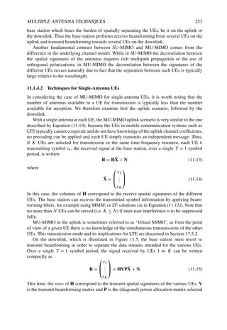

![MULTIPLE ANTENNA TECHNIQUES 255
downlink, or in the case of the uplink space-time coding could be used. Antenna selection is
another way of extracting more diversity out of the channel, as discussed in Section 17.5.
11.1.4.4 Comparing Single-User and Multi-User capacity
To illustrate the gains of multi-user multiplexing over single-user transmission, we compare
the sum-rate achieved by both types of system from an information theoretic standpoint,
for single antenna UEs. We compare the Shannon capacity in single-user and multi-user
scenarios both for an idealized synthetic channel and for a channel obtained from real
measurement data.
The idealized channel model assumes that the entries of the channel matrix H in
Equation (11.13) are independently and identically distributed (i.i.d.) Rayleigh fading. For
the measured channel case, a channel sounder was used5 to perform real-time wideband
channel measurements synchronously for two UEs moving at vehicular speed in an outdoor
semi-urban hilly environment with Line-Of-Sight (LOS) propagation predominantly present.
The most important parameters of the platform are summarized in Table 11.1.
Table 11.1 Parameters of the measured channel for SU-MIMO/MU-MIMO comparison.
More details can be found in references [7,8].
Parameter Value
Centre frequency 1917.6 MHz
Bandwidth 4.8 MHz
Base station transmit power 30 dBm
Number of antennas at base station 4 (2 cross polarized)
Number of UEs 2
Number of antennas at UE 1
Number of subcarriers 160
The sum-rate capacity of a two-UE MU-MIMO system (calculated assuming a zero-
forcing precoder as described in Section 11.1.4) is compared with the capacity of an
equivalent MISO system serving a single UE at a time (i.e. in TDMA), employing
beamforming (see Section 11.1.3.2). The base station has four antennas and the UE has a
single antenna. Full Channel State Information at the Transmitter (CSIT) is assumed in both
cases.
Figure 11.6 shows the ergodic (mean) sum-rate of both schemes in both channels. The
mean is taken over all frames and all subcarriers and subsequently normalized to bps/Hz. It
can be seen that in both the ideal and the measured channels, MU-MIMO yields a higher sum-
rate than SU-MISO in general. In fact, at high SNR, the multiplexing gain of the MU-MIMO
system is two while it is limited to one for the SU-MISO case.
However, for low SNR, the SU-MISO TDMA and MU-MIMO schemes perform very
similarly. This is because a sufficiently high SNR is required to excite more than one MIMO
transmission mode. Interestingly, the performance of both SU-MISO TDMA and MU-MIMO
5The Eurecom MIMO OpenAir Sounder (EMOS) [7].](https://image.slidesharecdn.com/ltefromtheorytopractise-240124145854-b0067765/85/LTE_from_Theory_to_Practise-pdf-282-320.jpg)
![256 LTE – THE UMTS LONG TERM EVOLUTION
−20 −15 −10 −5 0 5 10 15 20 25 30
0
2
4
6
8
10
12
14
16
18
SNR [dB]
Sum
rate
[bits/sec/Hz] MU−MIMO ZF iid
SU−MISO TDMA iid
MU−MIMO ZF measured
SU−MISO TDMA measured
Figure 11.6 Ergodic sum-rate capacity of SU-MISO TDMA and MU-MIMO with two UEs,
for an i.i.d. Rayleigh fading channel and for a measured channel.
is slightly worse in the measured channels than in the idealized i.i.d. channels. This can
be attributed to the correlation of the measured channel in time (due to the relatively slow
movement of the users), in frequency (due to the LOS propagation), and in space (due to the
transmit antenna correlation). In the MU-MIMO case the difference between the i.i.d. and the
measured channel is much higher than in the single-user TDMA case, since these correlation
effects result in a rank-deficient channel matrix.
11.2 MIMO Schemes in LTE
Building on the theoretical background of the previous section, the MIMO schemes adopted
for LTE are reviewed and explained. These schemes relate to the downlink unless otherwise
mentioned.
11.2.1 Practical Considerations
First, a few important practical constraints are briefly reviewed which affect the real-life
performance of the theoretical MIMO systems considered above, and which often are](https://image.slidesharecdn.com/ltefromtheorytopractise-240124145854-b0067765/85/LTE_from_Theory_to_Practise-pdf-283-320.jpg)
![MULTIPLE ANTENNA TECHNIQUES 257
decisive when selecting a particular transmission strategy in a given propagation and system
setting.
It was argued above that the full MIMO benefits (array gain, diversity gain and
multiplexing gain) assume ideally decorrelated antennas and full-rank MIMO channel
matrices. In this regard, the propagation environment and the antenna design (e.g. the
spacing) play a significant role. In the single-user case, the antennas at both the base station
and the UE are typically separated by between half a wavelength and a couple of wavelengths
at most. This distance is very short in relation to the distance from base station to UE. In a
LOS situation, this will cause a strong correlation between the spatial signatures, limiting
the use of multiplexing schemes. However, an exception to this can be created from the
use of antennas whose design itself provides the necessary orthogonality properties even in
LOS situations. An example is the use of two antennas (at both transmitter and receiver)
that operate on orthogonal polarizations (e.g. horizontal and vertical polarizations, or better,
so-called +45◦ and −45◦ polarizations, which give a twofold multiplexing capability even
in LOS). However, the use of orthogonal polarizations at the UEs may not always be
recommended as it results in non-omnidirectional beam patterns. Such exceptions aside,
in single-user MIMO the condition of spatial signature independence can only be satisfied
with the help of rich random multipath propagation. In diversity-oriented schemes, the
invertibility of the channel matrix is not required, yet the entries of the channel matrix should
be statistically decorrelated. Although a greater LOS to non-LOS energy ratio will tend to
correlate the fading coefficients on the various antennas, this effect will be compensated by
the reduction in fading delivered by the LOS component.
Another source of discrepancy between theoretical MIMO gains and practically achieved
performance lies in the (in-)ability of the receiver, and whenever needed the transmitter, to
estimate the channel coefficients perfectly. At the receiver, channel estimation is typically
performed over a finite sample of Reference Signals (RSs), as discussed in Chapter 8.
In the case of transmit beamforming and MIMO SVD-based precoding, the transmitter
then has to acquire this channel knowledge (or directly the precoder knowledge) from the
receiver usually through a limited feedback link, which causes further degradation to the
available CSIT.
With MU-MIMO, the principle advantages over SU-MIMO are clear: robustness with
respect to the propagation environment and spatial multiplexing gain preserved even in the
case of UEs with small numbers of antennas. However, such advantages come at a price. In
the downlink, MU-MIMO relies on the ability of the base station to compute the required
transmit beamformer, which in turn requires CSIT. The fundamental role of CSIT in the
MU-MIMO downlink can be emphasized as follows: in the extreme case of no CSIT being
available and identical fading statistics for all the UEs, the MU-MIMO gains disappear and
the SU-MIMO strategy becomes optimal [9].
As a consequence, one of the most difficult challenges in making MU-MIMO practical for
cellular applications, and particularly for an FDD system, is devising mechanisms that allow
for accurate Channel State Information (CSI) to be delivered by the UE to the base station in
a resource-efficient manner. This requires the use of appropriate codebooks for quantization.
These aspects are developed later in this chapter. A recent account of the literature on this
subject may also be found in reference [10].
Another issue which arises for practical implementations of MIMO schemes is the interac-
tion between the physical layer and the scheduling protocol. As noted in Section 11.1.4.1, in](https://image.slidesharecdn.com/ltefromtheorytopractise-240124145854-b0067765/85/LTE_from_Theory_to_Practise-pdf-284-320.jpg)

![MULTIPLE ANTENNA TECHNIQUES 259
Space-Frequency Block Codes (SFBCs)
If a physical channel in LTE is configured for transmit diversity operation using two eNodeB
antennas, pure SFBC is used. SFBC is a frequency-domain version of the well-known Space-
Time Block Codes (STBCs), also known as Alamouti codes [5]. This family of codes is
designed so that the transmitted diversity streams are orthogonal and achieve the optimal
SNR with a linear receiver. Such orthogonal codes only exist for the case of two transmit
antennas.
STBC is used in UMTS, but in LTE the number of available OFDM symbols in a subframe
is often odd while STBC operates on pairs of adjacent symbols in the time domain. The
application of STBC is therefore not straightforward for LTE, while the multiple subcarriers
of OFDM lend themselves well to the application of SFBC.
For SFBC transmission in LTE, the symbols transmitted from the two eNodeB antenna
ports on each pair of adjacent subcarriers are defined as follows:
y(0)(1) y(0)(2)
y(1)(1) y(1)(2)
=
x1 x2
−x∗
2 x∗
1
(11.17)
where y(p)(k) denotes the symbols transmitted from antenna port p on the kth subcarrier.
Since no orthogonal codes exist for antenna configurations beyond 2 × 2, SFBC has to be
modified in order to apply it to the case of 4 transmit antennas. In LTE, this is achieved by
combining SFBC with FSTD.
Frequency Switched Transmit Diversity (FSTD) and its Combination with SFBC
General FSTD schemes transmit symbols from each antenna on a different set of subcarriers.
For example, an FSTD transmission from 4 transmit antennas on four subcarriers might
appear as follows:
y(0)(1) y(0)(2) y(0)(3) y(0)(4)
y(1)(1) y(1)(2) y(1)(3) y(1)(4)
y(2)(1) y(2)(2) y(2)(3) y(2)(4)
y(3)(1) y(3)(2) y(3)(3) y(3)(4)
=
x1 0 0 0
0 x2 0 0
0 0 x3 0
0 0 0 x4
(11.18)
where, as previously, y(p)(k) denotes the symbols transmitted from antenna port p on the
kth subcarrier. In practice in LTE, FSTD is only used in combination with SFBC for the case
of 4 transmit antennas, in order to provide a suitable transmit diversity scheme where no
orthogonal rate-1 block codes exists. The LTE scheme is in fact a combination of two 2 × 2
SFBC schemes mapped to independent subcarriers as follows:
y(0)(1) y(0)(2) y(0)(3) y(0)(4)
y(1)(1) y(1)(2) y(1)(3) y(1)(4)
y(2)(1) y(2)(2) y(2)(3) y(2)(4)
y(3)(1) y(3)(2) y(3)(3) y(3)(4)
=
x1 x2 0 0
0 0 x3 x4
−x∗
2 x∗
1 0 0
0 0 −x∗
4 x∗
3
(11.19)
Note that mapping of symbols to antenna ports is different in the 4 transmit-antenna case
compared to the 2 transmit-antenna SFBC scheme. This is because the RS density on the third
and fourth antenna ports is half that of the first and second antenna ports (see Section 8.2),](https://image.slidesharecdn.com/ltefromtheorytopractise-240124145854-b0067765/85/LTE_from_Theory_to_Practise-pdf-286-320.jpg)

![MULTIPLE ANTENNA TECHNIQUES 261
one of the common antenna ports actually uses one of the elements of the phased array.
The eNodeB could then, over time, establish a suitable offset to apply to the CQI reports
received from the UE to adapt them to the actual quality of the beamformed signal. Such
an offset might, for example, be derived from the proportion of transport blocks positively
acknowledged by the UE. An eNodeB antenna configuration of this kind also allows the
possibility to use beamforming for UEs near the edge of the cell, while other antenna ports
may be used for SU-MIMO spatial multiplexing to deliver high data rates to UEs closer to
the eNodeB.
Another factor to consider when deploying beamforming in LTE is that it can only be
applied to the PDSCH and not to the control channels. Typically the range of the PDSCH
can therefore be extended by beamforming, but the overall cell range may still be limited by
the range of the control channels unless other measures are taken. One approach could be
to reduce the code rate used for the control channels when beamforming is applied to the
PDSCH.
The effect of beamforming on neighbouring cells should also be taken into account. If the
beamforming is intermittent, it can result in a problem often known as the ‘flash light effect’,
where strong intermittent interference may disturb the accuracy of the UEs’ CQI reporting
in adjacent cells. This effect was shown to have the potential to cause throughput reductions
in HSDPA [11], but in LTE the possibility for frequency-domain scheduling in OFDMA (as
discussed in Section 12.5) provides an additional degree of freedom to avoid such issues.
11.2.2.3 Spatial Multiplexing Schemes
Introduction
We begin by introducing some terminology used to describe spatial multiplexing in LTE:
• A spatial layer is the term used in LTE for the different streams generated by spatial
multiplexing as described in Section 11.1. A layer can be described as a mapping
of symbols onto the transmit antenna ports. Each layer is identified by a (precoding)
vector of size equal to the number of transmit antenna ports and can be associated with
a radiation pattern.
• The rank of the transmission is the number of layers transmitted.
• A codeword is an independently encoded data block, corresponding to a single
Transport Block (TB) delivered from the Medium Access Control (MAC) layer in the
transmitter to the physical layer, and protected with a CRC.
For ranks greater than 1, two codewords can be transmitted. Note that the number of
codewords is always less than or equal to the number of layers, which in turn is always less
than or equal to the number of antenna ports.
In principle, a SU-MIMO spatial multiplexing scheme can either use a single codeword
mapped to all the available layers, or multiple codewords each mapped to one or more
different layers.
The main benefit of using only one codeword is a reduction in the amount of control
signalling required, both for CQI reporting, where only a single value would be needed for
all layers, and for HARQ ACK/NACK feedback, where only one ACK/NACK would have](https://image.slidesharecdn.com/ltefromtheorytopractise-240124145854-b0067765/85/LTE_from_Theory_to_Practise-pdf-288-320.jpg)
![262 LTE – THE UMTS LONG TERM EVOLUTION
Table 11.2 Codeword-to-layer mapping in LTE.
Codeword 1 Codeword 2
Rank 1 Layer 1
Rank 2 Layer 1 Layer 2
Rank 3 Layer 1 Layer 2 and Layer 3
Rank 4 Layer 1 and Layer 2 Layer 3 and Layer 4
to be signalled per subframe per UE. In such a case, the MLD receiver is optimal in terms of
minimizing the bit error rate.
At the opposite extreme, a separate codeword could be mapped to each of the layers. The
advantage of this type of scheme is that significant gains are possible by using Successive
Interference Cancellation (SIC), albeit at the expense of more signalling being required.
An MMSE-SIC receiver can be shown to approach the Shannon capacity [6]. Note that an
MMSE receiver is viable for both transmitter structures. For LTE, a middle-way was adopted
whereby at most two codewords are used, even if four layers are transmitted. The codeword-
to-layer mapping is static, since only minimal gains were shown for a dynamic mapping
method. The mappings are shown in Table 11.2. Note that in LTE all RBs belonging to the
same codeword use the same MCS, even if a codeword is mapped to multiple layers.
Precoding
The PDSCH transmission modes for open-loop spatial multiplexing9 and closed-loop spatial
multiplexing10 use precoding from a defined ‘codebook’ to form the transmitted layers. Each
codebook consists of a set of predefined precoding matrices, with the size of the set being a
trade-off between the number of signalling bits required to indicate a particular matrix in the
codebook and the suitability of the resulting transmitted beam direction.
In the case of closed-loop spatial multiplexing, a UE feeds back to the eNodeB the
most desirable entry from a predefined codebook. The preferred precoder is the matrix
which would maximize the capacity based on the receiver capabilities. In a single-cell,
interference-free environment the UE will typically indicate the precoder that would result in
a transmission with an effective SNR following most closely the largest singular values of its
estimated channel matrix.
Some important properties of the LTE codebooks are as follows:
• Constant modulus property. LTE uses precoders which mostly comprise pure phase
corrections – that is, with no amplitude changes. This is to ensure that the Power
Amplifier (PA) connected to each antenna is loaded equally. The one exception (which
still maintains the constant modulus property) is using an identity matrix as the
precoder. However, although the identity precoder may completely switch off one
antenna on one layer, since each layer is still connected to one antenna at constant
power the net effect across the layers is still constant modulus to the PA.
9PDSCH transmission mode 3 – see Section 9.2.2.1.
10PDSCH transmission modes 4 and 6 – see Section 9.2.2.1.](https://image.slidesharecdn.com/ltefromtheorytopractise-240124145854-b0067765/85/LTE_from_Theory_to_Practise-pdf-289-320.jpg)
![MULTIPLE ANTENNA TECHNIQUES 263
• Nested property. The nested property is a method of arranging the codebooks of
different ranks so that the lower rank codebook is comprised of a subset of the higher
rank codebook vectors. This property simplifies the CQI calculation across different
ranks. It ensures that the precoded transmission for a lower rank is a subset of the
precoded transmission for a higher rank, thereby reducing the number of calculations
required for the UE to generate the feedback. For example, if a specific index in the
codebook corresponds to the columns 1, 2 and 3 from the precoder W in the case of
a rank 3 transmission, then the same index in the case of rank 2 transmission must
consist of either columns 1 and 2 or columns 1 and 3 from W.
• Minimal ‘complex’ multiplications. The 2-antenna codebook consists entirely of a
QPSK alphabet, which eliminates the need for any complex multiplications since all
codebook multiplications use only ±1 and ±j. The 4-antenna codebook does contain
some QPSK entries which require a
√
2 magnitude scaling as well; it was considered
that the performance gain of including these precoders justified the added complexity.
The 2-antenna codebook in LTE is comprised of one 2 × 2 identity matrix and two DFT
(Discrete Fourier Transform) matrices:
1 0
0 1
,
1 1
1 −1
and
1 1
j −j
(11.20)
Here the columns of the matrices correspond to the layers.
The 4 transmit antenna codebook in LTE uses a Householder generating function:
WH = I − 2uuH
/uH
u, (11.21)
which generates unitary matrices from input vectors u, which are defined in reference [12].
The advantage of using precoders generated with this equation is that it simplifies the CQI
calculation (which has to be carried out for each individual precoder in order to determine the
preferred precoder) by reducing the number of matrix inversions. This structure also reduces
the amount of control signalling required, since the optimum rank 1 version of WH is always
the first column of WH; therefore the UE only needs to indicate the preferred precoding
matrix, and not also the individual vector within it which would be optimal for the case of
rank 1 transmission.
Note that both DFT and Householder matrices are unitary.
Cyclic Delay Diversity (CDD)
In the case of open-loop spatial multiplexing,11 the feedback from the UE indicates only
the rank of the channel, and not a preferred precoding matrix. In this mode, if the rank
used for PDSCH transmission is greater than 1 (i.e. more than one layer is transmitted),
LTE uses Cyclic Delay Diversity (CDD) [13]. CDD involves transmitting the same set of
OFDM symbols on the same set of OFDM subcarriers from multiple transmit antennas, with
a different delay on each antenna. The delay is applied before the Cyclic Prefix (CP) is added,
thereby guaranteeing that the delay is cyclic over the Fast Fourier Transform (FFT) size. This
gives CDD its name.
11PDSCH transmission mode 3 – see Section 9.2.2.1.](https://image.slidesharecdn.com/ltefromtheorytopractise-240124145854-b0067765/85/LTE_from_Theory_to_Practise-pdf-290-320.jpg)
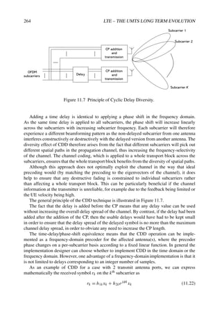


![268 LTE – THE UMTS LONG TERM EVOLUTION
LTE, and that more sophisticated and resource-efficient solutions for channel estimation and
feedback will play a crucial role in making these techniques a practical success.
Many variations of MU-MIMO may be considered, and the choice of a particular
algorithm reflects a compromise between complexity, performance and the amount of
feedback necessary to convey the CSIT to the eNodeB. In this Section we describe the main
aspects of MU-MIMO techniques which emerged during the development of LTE, with the
aim of highlighting the available technical solutions and the challenges which remain.
11.2.3.1 Precoding Strategies and Supporting Signalling
MU-MIMO is particularly beneficial for increasing total cell throughput in the downlink:
when the eNodeB has N transmit antennas and U ≥ N UEs are present in the cell, it is well
known that the full multiplexing gain N can be achieved even when each UE has only a
single antenna, by using Spatial Division Multiple Access (SDMA) schemes based on linear
precoding for transmit beamforming. Moreover, when the number of active UEs in the cell is
large, a significant portion of the MU-MIMO throughput gain can be secured by exploiting
multi-user diversity through relatively simple UE-selection mechanisms. All these benefits,
however, depend on the level of CSIT that the eNodeB receives from each UE.
In the case of SU-MIMO, it has been shown that even a small number of feedback bits
per antenna can be very beneficial in steering the transmitted energy more accurately towards
the UE’s antenna(s) [14–17]. More precisely, in SU-MIMO channels the accuracy of CSIT
only causes an SNR offset, but does not affect the slope of the capacity-versus-SNR curve
(i.e. the multiplexing gain). Yet for the MU-MIMO downlink, the level of CSI available at
the transmitter does affect the multiplexing gain, because a MU-MIMO system with finite-
rate feedback is essentially interference-limited, where the crucial interference rejection
processing is carried out by the transmitter. Hence, providing accurate channel feedback is
considerably more important for MU-MIMO than for SU-MIMO.
On the other hand, in a system with a large number of UEs, if all the UEs are to report
very accurate channel measurements, the total amount of uplink resources required for CSIT
feedback may soon outweigh the increase in system throughput provided by MU-MIMO
techniques. Recent published results show that, given a total feedback budget, considerably
higher throughput is achieved by receiving very accurate channel feedback from a relatively
small fraction of the UEs, selected according to some appropriate criterion, rather than coarse
feedback from many UEs [18].
One general solution to the problem of limited CSIT feedback in MU-MIMO schemes
is that of utilizing a codebook of Nq = 2B N-dimensional vectors and sending to the base
station a B-bit index from the codebook, selected according to some minimum-distance
criterion. The codebook indices are then used by the base station to construct the precoding
matrix. Typically, a real-valued CQI is also sent along with the codebook index, which can
be used by the base station for MCS selection as well as user selection [17,19–22].
Two main precoding techniques emerged as MU-MIMO candidates for LTE, both relying
on a codebook-based limited feedback concept.
1. Codebook of Unitary Precoding (UP) matrices. The codebook contains a set of
L = Nq/N predefined and fixed unitary beamforming matrices of size N × N. For
each beamforming matrix in the codebook, each UE computes an SINR for each of
the N beamforming vectors in the matrix, assuming that the other N − 1 vectors are](https://image.slidesharecdn.com/ltefromtheorytopractise-240124145854-b0067765/85/LTE_from_Theory_to_Practise-pdf-295-320.jpg)

![270 LTE – THE UMTS LONG TERM EVOLUTION
to feed back; (2) the codebooks for feedback calculation by the UEs and precoder selection
by the eNodeB; (3) the method and procedure for signalling the precoding weights used for
transmission to the relevant UEs. These three aspects are described in more detail in the
following.
11.2.3.2 Calculation of Precoding Vector Indicator (PVI) and CQI
As MU-MIMO in LTE supports only rank-1 transmission, i.e. one codeword, to each of the
selected UEs, we refer to the precoding feedback as a Precoding Vector Indicator (PVI) for
the purposes of this discussion (although in the LTE specifications the term PMI is used for
both SU-MIMO and MU-MIMO).
We focus on two different assumptions which a UE could theoretically make as to
the nature of the interfering precoding vectors when calculating the feedback information.
Each assumption corresponds to one of the MU-MIMO precoding techniques described
above. We also show that the two sets of assumptions lead to similar results, and indeed
the feedback values reported by the UE are equivalent. Under certain assumptions on the
codebook structure and number of interferers, the two limited feedback concepts introduced
above provide identical information to the transmitter; the main difference between the two
approaches in fact lies in the way the precoder is selected based on the information collected
by the eNodeB.
Precoder and feedback calculation methods
For the purpose of analysis, consider a codebook for feedback from the UEs, C =
{C(0), . . . , C(L−1)}, consisting of L unitary matrices of size N × N, N being the number
of transmit antennas, such that the overall codebook size in number of vectors is Nq = LN.
The MU-MIMO channel in a given subframe with linear precoding applied at the transmitter
is given by
r = HWx + n (11.27)
where x, with E[xxH] = I, is the vector of independent data symbols transmitted in parallel by
the N transmit antennas, r = (r0, . . . , rK−1)T is the vector of signals individually received
by the K users and n ∼ CN(0, I) is an i.i.d. complex Gaussian noise vector.12 The matrix
H = [hT
0 , . . . , hT
K−1]T contains the channel coefficients from the N antennas to the K UEs,
where the row vector hk is the channel of UE k.13 The transmission is power-constrained
such that
trace(WH
W) ≤ Pt (11.28)
where Pt denotes the total downlink transmitted power (energy per subframe). The precoding
matrix, W, can be rewritten in the form
W = F diag (p)1/2
(11.29)
12Here the noise variance, which includes the thermal noise and possibly other interference sources modelled as
Gaussian, is normalized to one without loss of generality. In fact, the power constraint P introduced next can be
regarded as an SNR value.
13For the moment it is assumed that each UE uses one receiving antenna.](https://image.slidesharecdn.com/ltefromtheorytopractise-240124145854-b0067765/85/LTE_from_Theory_to_Practise-pdf-297-320.jpg)
![MULTIPLE ANTENNA TECHNIQUES 271
where the matrix F is designed without a power constraint, and the kth coefficient of vector
p, denoted by pk, is the power level for UE k. Let S denote the set of UEs selected for
transmission. We also assume equal power allocation across these UEs.
Therefore, if the precoding matrix is unitary, according to MU-MIMO precoding tech-
nique 1 above, it follows that
F(S) ∈ {C(0)
(S), . . . , C(L−1)
(S)} and pk = Pt /|S| (11.30)
where the notation C(i)(S) indicates that the precoding matrix can contain only a subset of
vectors of codebook matrix C(i). As mentioned in Section 11.2.2.4, this is referred to as
‘codebook subset selection’.
If F is the zero-forcing solution, according to MU-MIMO precoding technique 2 above,
then the precoder can be expressed as
F(S) = Ĥ(S)H
(Ĥ(S)Ĥ(S)H
)−1
and pk = Pt /(|S| · fk
2
) (11.31)
where fk denotes the kth column of F and Ĥ(S) = [ĥT
1 , . . . , ĥT
|S|]T, contains the quantized
channel vectors of the selected UEs.
We also introduce the cross-talk matrix []i,j = |hifj |2, such that the received SINR for
user k is given by
γk =
pk[]k,k
1 +
i=k pi[]k,i
(11.32)
Let us consider the following two methods of calculating an index (the PVI) from the
codebook and a real-value quantity signifying an SINR estimate (the CQI).
1. In MU-MIMO precoding technique 1 above (codebook of UP matrices), the following
two operations are carried out by each UE:
• The SINR is computed using Equation (11.32) for each vector in the codebook
taken as the UE’s own precoding vector. The interfering precoding vectors are
assumed to be the other N − 1 vectors in the codebook which are orthogonal to
the UE’s own.
• The largest such SINR is used to report the CQI value, while the index of the
corresponding useful precoding vector represents the PVI.
2. In MU-MIMO precoding technique 2 above (codebook for CVQ), the following
operations are performed instead:
• The measured channel vector14 is quantized to the nearest vector in the codebook
in terms of chordal distance (see, for example, reference [23]). The quantization
index represents the PVI.
• An expected SINR is estimated under the following assumptions:
– There are N − 1 interfering precoding vectors and they are isotropically
distributed on the hyperplane orthogonal to the PVI vector (i.e. the UE
assumes that zero-forcing beamforming will be used).
14Still assuming that each UE uses one receiving antenna.](https://image.slidesharecdn.com/ltefromtheorytopractise-240124145854-b0067765/85/LTE_from_Theory_to_Practise-pdf-298-320.jpg)
![272 LTE – THE UMTS LONG TERM EVOLUTION
– The useful precoding vector is only slightly offset from the PVI vector – i.e.
the angle between the two vectors is small.
It is easy to show that the operations for MU-MIMO precoding technique 1 equate to
performing vector quantization on the channel vector with minimum chordal distance. We
also show below that the PVI/CQI values for the two methods are totally equivalent, under
the assumptions stated above.
Equivalence between channel vector quantization and PVI calculation
Let us rewrite the SINR for a generic UE k, when the selected precoding matrix is C(i) =
[c(i)
0 , . . . , c(i)
N−1], and the reference UE’s own precoding vector is c(i)
j . We denote this SINR
as γk[c
(i)
j ] and define the angle θ
(i)
k,j ∈ [0, π/2] between vectors h̃H
k and c
(i)
j , where h̃k =
hk/ hk , as
cos θ(i)
k,j = |h̃H
k , c(i)
j | = |c(i)H
j h̃H
k | (11.33)
where · denotes the inner product. As C(i) is a generator matrix for CN , we can decompose
h̃H
k as
h̃H
k = αj c(i)
j +
l=j
αlc(i)
l (11.34)
where αl = h̃H
k , c
(i)
l for l = 0, . . . , N − 1. It follows that ˜
hk
2 =
N−1
l=0 α2
l = 1. There-
fore, if the precoding matrix is F = C(i), the power is equally distributed across the N
precoding vectors, and UE k has reported vector c(i)
j as PVI, by substituting Equation (11.34)
into (11.32) we obtain
γk(c(i)
j ) =
(P/N) hk
2 cos2 θ
(i)
k,j
1 + (P/N) hk
2 sin2
θ
(i)
k,j
(11.35)
The reported PVI can be interpreted as an approximate representation of the conjugate
channel vector, Q(h̃H
k ), where Q(·) denotes a vector-quantization operation. More precisely,
the reported PVI corresponds to the vector in the codebook with minimum chordal distance
from h̃H
k , i.e.
Q(h̃H
k ) = argmin
c
(i)
j ∈C
sin θ(i)
k,j = argmax
c
(i)
j ∈C
γk[c(i)
j ] (11.36)
In Figure 11.9 θ1 is used to denote this minimum quantization angle for the channel vector
of UE 1. Figure 11.9 shows a graphical representation of the channel vector, the selected PVI
and the precoding vectors for MU-MIMO precoding technique 1. Note that the precoding
vectors {f1, f2, f3} are the columns of the selected unitary matrix from the codebook.
Let us now consider MU-MIMO precoding technique 2 illustrated in Figure 11.10. In this
case the UE directly seeks to represent the channel vector h̃H
k as accurately as possible by one
of the vectors in the codebook.15
15It is clearly equivalent to represent vector h̃T
k by an element of the codebook C∗, obtained from C by taking
the conjugate of its vector components. In the case of a DFT-based codebook, depending on whether h̃H
k or h̃T
k
is quantized, we can use the inverse DFT and DFT matrices respectively (or vice versa) as base matrices for the
generation of the two codebooks, as CDFT = C∗
IDFT. The resulting quantization vectors are the conjugate of each
other.](https://image.slidesharecdn.com/ltefromtheorytopractise-240124145854-b0067765/85/LTE_from_Theory_to_Practise-pdf-299-320.jpg)

![274 LTE – THE UMTS LONG TERM EVOLUTION
by Equation (11.36), and can be rewritten as
Q(h̃H
k ) = argmin
cn∈C
sin θk,n = argmax
cn∈C
γk(cn) (11.37)
When channel vector quantization and zero-forcing precoding are used, the UEs know
only the vector they are assuming for their own transmissions when deriving the PVI to
report; they do not know in advance the other vectors which will eventually be used to
make up the full precoding matrix, and therefore they cannot predict the exact SINR value.
However, they can derive a good approximation of the SINR averaged over the unknown
components of the precoding matrix. The final expression, which is an approximate lower-
bound to the average SINR at the UE, is very similar to Equation (11.35) and is expressed as
follows:16
E[γk]
pk hk
2 cos2 θk
1 + (P/N) hk
2 sin2
θk
(11.38)
As pk is known to the eNodeB but unknown to the UE, the CQI sent by UE k, according
to MU-MIMO precoding technique 2 is the same as Equation (11.35), i.e.
CQIk =
(P/N) hk
2 cos2 θk
1 + (P/N) hk
2 sin2 θk
(11.39)
The eNodeB can then estimate the SINR at UE k by a simple scaling operation: γk =
(pk/(P/N))CQIk. Note that the ratio (pk/(P/N)) = 1 for every k if the precoding matrix is
unitary.
From the analysis so far we can conclude that the only substantial difference between the
two MU-MIMO precoding techniques of Section 11.2.3.1 is in the use of the same PVI and
CQI information by the eNodeB to construct the precoding matrix. In MU-MIMO precoding
technique 1 the choice is restricted to a precoder matched to the selected PVIs, which have
to be orthogonal. In MU-MIMO precoding technique 2, the PVIs of the selected UEs need
not be exactly orthogonal and the eNodeB would be allowed to adjust the precoder in order
to minimize any residual interference among UEs.
In practice, only unitary codebooks are provided in the first version of LTE, and PDSCH
transmission in MU-MIMO mode17 is based on selection of precoding matrices from the
same codebooks as are used for SU-MIMO (as summarized in Section 11.2.2.3 above).
In the light of the above discussion on MU-MIMO techniques, it is instructive to
observe that the LTE 2-antenna codebook, and also the first eight entries in the 4-antenna
codebook, are in fact DFT-based codebooks – in other words derived from a discrete Fourier
transformation matrix. The main reasons for this choice are as follows:
• Simplicity in the PVI/CQI calculation, which can be done in some cases without
complex multiplications.
• A DFT matrix nicely captures the characteristics of a highly correlated MISO channel.
In fact, it is not difficult to see that, if the first N rows are taken from a DFT matrix of
size Nq, each of the Nq column vectors that is obtained contains the phases of (i.e. the
16The derivation of this formula can be found, for example, in [20].
17PDSCH transmission mode 5 – see Section 9.2.2.1.](https://image.slidesharecdn.com/ltefromtheorytopractise-240124145854-b0067765/85/LTE_from_Theory_to_Practise-pdf-301-320.jpg)
![MULTIPLE ANTENNA TECHNIQUES 275
baseband representation of) a line-of-sight propagation channel from a uniform linear
array with N elements to a point in space located at a given angle with respect to the
antenna array boresight (see, for example, reference [6]).
• It is also easy to verify that the vectors in such a codebook can be grouped into L =
Nq/N unitary matrices.
11.2.3.3 User Selection Mechanism
As is clear from the discussion above, one important aspect of MU-MIMO precoding is
the selection of UEs for transmission, as the throughput gain of naive linear precoding
techniques very much depends on exploiting the multi-user diversity available in the system.
Although the method for selecting UEs is not specified in LTE or other similar systems, we
briefly review two very simple strategies which could be appropriate for implementation in
conjunction with the precoding methods that we have considered.
One simple way of selecting UEs, according to MU-MIMO precoding technique 1 of
Section 11.2.3.1, is to group UEs that report orthogonal PVIs and select the group providing
the highest total throughput. This can be simply estimated, for example from the capacity
formula R =
k log (1 + SINRk), where the summation is over the UEs in the group and
the SINR value is given by the CQI.
Another more general and very simple greedy strategy, which would be appropriate for
MU-MIMO precoding technique 2, consists of adding one UE at a time, as long as the
additional UE increases the overall throughput, estimated according to a criterion such as
the achievable sum-rate. This simple strategy can be described as follows (see, for example
reference [24]). Let R(S) denote the achievable sum-rate when the set of UEs S is selected
for transmission.
User selection algorithm
Initialize S = ∅, R(S) = 0.
while |S| ≤ N do
1. k̄ = argmax
k/
∈S
R(S ∪ {k})
2. if R(S ∪ {k̄}) R(S) update S = S ∪ {k̄}, else exit.
11.2.3.4 Receiver Spatial Equalizers
Since in LTE each UE is assumed to support two receiving antennas, it is important to
consider the possible receive beamforming structures for MU-MIMO transmission, which
may affect the PVI and CQI calculation.18
We consider the possibilities for receiver beamforming in terms of a generic UE k with J
antenna elements, and we use Hk = [hT
1 , . . . , hT
J ]T to denote a J × N channel for that UE.
18Note that receiver algorithms are not defined in the specifications; instead, the required demodulation
performance is specified.](https://image.slidesharecdn.com/ltefromtheorytopractise-240124145854-b0067765/85/LTE_from_Theory_to_Practise-pdf-302-320.jpg)
![276 LTE – THE UMTS LONG TERM EVOLUTION
We also use H̄k = HkF = [h̄k,0, . . . , h̄k,N−1] to denote the product matrix between the
reference UE’s channel and the precoder, as defined in Equation (11.29).
Using this terminology, we describe three possible spatial equalizers, which all attempt to
maximize the received SINR, with different degrees of knowledge at the UE side.
1. MMSE receiver. If the precoding vector for the reference UE k corresponds to the jth
column of F, then the 1 × J vector of receiver combining coefficients, wk,j , is given
by19
wk,j = h̄H
k,j (H̄kH̄H
k + IJ )−1
(11.40)
This receiver requires that the user estimates the N vectors of size J in the product
matrix H̄k. This knowledge can be acquired by estimating the channel matrix from the
cell-specific RS and being told by explicit signalling which precoding matrix is used.
Alternatively, if precoded RS were to be provided, the product matrix could be directly
estimated from them. It goes without saying that the former method is best suited for
a MU-MIMO scheme with a small set of possible precoding matrices, while the latter
allows for full flexibility in the construction of the precoding matrix.
2. Minimum Quantization Error (MQE) receiver. In this case, for a given vector of the
codebook, cn, the coefficients of the linear combination at the receiver k are given by
wk,n = αh
(eff)
k,n H†
k (11.41)
where H†
k = HH
k (HkHH
k )−1 is the right pseudo-inverse of Hk, α is a normalization
factor, such that wk,n = 1, and (the row vector) h(eff)
k,n is the projection of cH
n onto
span(HT
k ). To express this algebraically, let QT
k = [qT
k,1, . . . , qT
k,J ] be a generator
matrix for span(HT
k ), then
h(eff)
k,n = cH
n QH
k Qk (11.42)
For the derivation of this receiver we refer the interested reader to [25]. Note that the
structure of Equation (11.41) is very similar to (11.40), but calculation of (11.41) does
not require knowledge of the precoding matrix. This is because it minimizes the vector
quantization error independently of the transmit beamformer, and by doing so it also
maximizes the CQI value in Equation (11.39).
3. SVD of the channel. This naive receive beamformer depends only on the channel
matrix Hk and is independent of any CSI feedback. Let Hk = UkkTH
k be the SVD
of the channel, with singular values λk,1 ≥ λk,2 ≥ · · · ≥ λk,J (J ≤ N), and Uk =
[uk,1, . . . , uk,J ]. Then
wk = uH
k,1 (11.43)
11.2.4 Physical-Layer MIMO Performance
In this section we present some link-level and system-level simulation results to illustrate the
physical layer performance of various MIMO schemes, starting with SU-MIMO and then
followed by MU-MIMO schemes. Some of these results were influential in deciding on the
MIMO schemes for LTE.
19Note that the noise variance is normalized to 1 as it is included in the transmit SNR, P .](https://image.slidesharecdn.com/ltefromtheorytopractise-240124145854-b0067765/85/LTE_from_Theory_to_Practise-pdf-303-320.jpg)
![MULTIPLE ANTENNA TECHNIQUES 277
−5 0 5 10 15 20
0
2
4
6
8
10
12
14
16
18
20
Geometry (dB)
%
Throughput
Gains
over
Virtual
AS
, ,
4-DFT
CMHH
Figure 11.11 Throughput gain achieved by precoding with two different codebooks,
compared to antenna selection: 4 × 2. Reproduced by permission of © Texas Instruments.
11.2.4.1 Precoding Performance
To demonstrate the benefits of precoding, link-level simulation results [26] in Figures 11.11
and 11.12 show the percentage throughput gains versus geometry (average SINR) when
compared to antenna selection. The channel model here is the SCM-D (see Section 21.3.5)
with a uniform linear array with 4λ (uncorrelated frequency selective fading) antenna
spacing. Clearly the precoding gains are greater in the 4 × 2 case than in the 4 × 4 case,
as expected. Similar gains compared to antenna selection are shown in reference [27]. The
legends in Figures 11.11 and 11.12 refer to different codebook designs as follows:
• CMHH: Constant Modulus HouseHolder;
• 4-DFT: codebook based on four DFT matrices. This is also referred to as the
unoptimized or regular DFT codebook, since the different matrices are not optimized
to maximize the minimum chordal distance.
The 4-antenna LTE codebook performs similarly to the CMHH codebook.](https://image.slidesharecdn.com/ltefromtheorytopractise-240124145854-b0067765/85/LTE_from_Theory_to_Practise-pdf-304-320.jpg)

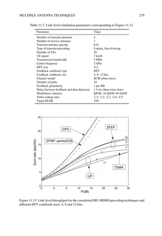
![280 LTE – THE UMTS LONG TERM EVOLUTION
2 3 4 5 6 7 8
4.5
5
5.5
6
6.5
7
7.5
8
8.5
9
9.5
10
Feedback bits per RB
Cell
throughput
(bps/Hz)
ZFEP 4x1
UP 4x1
ZFEP MMSE-Rx 4x2
ZFEP MQE-Rx 4x2
UP MMSE-Rx 4x2
Figure 11.14 System level simulation results for two different precoding strategies and two
different linear spatial equalizers (with 2 Rx antennas).
almost orthogonal channel signatures. For comparison, Figure 11.13 also shows the optimal
channel sum-rate capacity (achieved by ‘Dirty-Paper Coding’ (DPC) [28]) and the achievable
throughput for zero-forcing precoding with perfect CSIT and water-filling power allocation.
Figure 11.14 shows some system-level results for the two precoding schemes and M =
1, 2 receiving antennas. The feedback generation is done under the assumption of an
MMSE receiver for unitary precoding, by using the MMSE solution in Equation (11.40); the
strategy for zero-forcing is quantization error minimization according to Equation (11.41).
The suffix ‘MMSE’ denotes the curves obtained by applying the MMSE spatial filter in
Equation (11.40), and ‘MQE’ indicates the zero-forcing curve where the spatial equalizer in
Equation (11.41) is used for both feedback calculation and data detection. The system-level
simulation parameters are as in Table 11.3 except where shown in Table 11.4.
It can be observed that the cell throughput with Zero-Forcing Equal Power (ZFEP) slightly
decreases with the granularity of the channel quantization for a number of reported bits
per index larger than six. The explanation for this is the suboptimality of the UE selection
mechanism. In fact, for a small codebook size UEs with very similar channel signatures fall
into the same quantization bin, and hence two such UEs are never selected simultaneously
(otherwise the resulting MIMO channel would be singular). Conversely, for larger codebooks
two UEs with similar separation of their channel signatures may fall into separate bins,
and they may be selected for transmission as a result of the proportional fair scheduling
mechanism, thus causing slight degradation in throughput.](https://image.slidesharecdn.com/ltefromtheorytopractise-240124145854-b0067765/85/LTE_from_Theory_to_Practise-pdf-307-320.jpg)

![282 LTE – THE UMTS LONG TERM EVOLUTION
Single-User MIMO techniques are well-developed in the first version of LTE, providing
the possibility to benefit from precoding white avoiding a high control signalling overhead.
However, it is clear that the early techniques leave substantial scope for further development
and enhancement in later releases of the LTE specifications.
References20
[1] D. Gesbert, M. Shafi, P. Smith, D. Shiu and A. Naguib, ‘From Theory to Practice: An
Overview of MIMO Space-time Coded Wireless Systems’. IEEE Journal on Selected Areas in
Communications. Special Issue on MIMO systems, guest edited by the authors, April 2003.
[2] H. Bölcskei, D. Gesbert, C. Papadias and A. J. van der Veen (eds), Space-Time Wireless Systems:
From Array Processing to MIMO Communications. Cambridge: Cambridge University Press,
2006.
[3] A. Goldsmith, Wireless Communications. Cambridge: Cambridge University Press, 2005.
[4] G. Golub and C. van Loan, Matrix Computations. Balitmore, MA: John Hopkins University Press,
1996.
[5] S. M. Alamouti, ‘A Simple Transmitter Diversity Technique for Wireless Communications’. IEEE
Journal on Selected Areas in Communications, Vol. 16, pp. 1451–1458, October 1998.
[6] D. Tse and P. Viswanath, Fundamentals of Wireless Communication. Cambridge: Cambridge
University Press, 2004.
[7] F. Kaltenberger, L. S. Cardoso, M. Kountouris, R. Knopp and D. Gesbert, ‘Capacity of Linear
Multi-user MIMO Precoding Schemes with Measured Channel Data’, in Proc. IEEE Workshop
on Sign. Proc. Adv. in Wireless Comm. (SPAWC), Recife, Brazil, July 2008.
[8] F. Kaltenberger, M. Kountouris, D. Gesbert and R. Knopp, ‘Correlation and Capacity of Measured
Multi-user MIMO Channels’, in Proc. IEEE International Symposium on Personal, Indoor and
Mobile Radio Communications, Cannes, France, September 2008.
[9] Caire, G. and Shamai, S. (Shitz), ‘On the Achievable Throughput of a Multi-antenna Gaussian
Broadcast Channel’. IEEE Trans. on Information Theory, Vol. 49, pp. 1691–1706, July 2003.
[10] R. Heath, V. Lau, D. Love, D. Gesbert, B. Rao and A. Andrews, (eds), ‘Exploiting Limited
Feedback in Tomorrow’s Wireless Communications Networks’. Special issue of IEEE Journal
on Selected Areas in Communications, October 2008.
[11] A. Osseiran and A. Logothetis, ‘Closed Loop Transmit Diversity in WCDMA HS-DSCH’, in
Proc. IEEE Vehicular Technology Conference, May 2005.
[12] 3GPP Technical Specification 36.211, ‘E-UTRA physical channels and modulation (Release 8)’,
www.3gpp.org.
[13] Y. Li, J. Chuang and N. Sollenberger, ‘Transmitter Diversity for OFDM Systems and Its Impact
on High-Rate Data Wireless Networks’. IEEE Journal on Selected Areas in Communications,
Vol. 17, pp. 1233–1243, July 1999.
[14] A. Narula, M. J. Lopez, M. D. Trott and G. W. Wornell, ‘Efficient Use of Side Information in
Multiple Antenna Data Transmission over Fading Channels’. IEEE Journal on Selected Areas in
Communications, Vol. 16, pp. 1223–1436, October 1998.
[15] D. Love, R. Heath Jr and T. Strohmer, ‘Grassmannian Beamforming for Multiple-input Multiple-
output Wireless Systems’. IEEE Trans. on Information Theory, Vol. 49, pp. 2735–2747, October
2003.
20All web sites confirmed 18th December 2008.](https://image.slidesharecdn.com/ltefromtheorytopractise-240124145854-b0067765/85/LTE_from_Theory_to_Practise-pdf-309-320.jpg)
![MULTIPLE ANTENNA TECHNIQUES 283
[16] D. Love, R. Heath Jr, W. Santipach, and M. Honig, ‘What is the Value of Limited Feedback for
MIMO Channels?’. IEEE Communication Magazine, Vol. 42, pp. 54–59, October 2003.
[17] N. Jindal, ‘MIMO Broadcast Channels with Finite Rate Feedback’. IEEE Trans. Information
Theory, Vol. 52, pp. 5045–5059, November 2006.
[18] R. Zakhour and D. Gesbert, ‘Adaptive Feedback Rate Control in MIMO Broadcast Systems’, in
Proc. of IEEE Information Theory Workshop (ITW), San Diego, CA, January 2008.
[19] N. Jindal, ‘MIMO Broadcast Channels with Finite Rate Feedback’, in Proc. IEEE Global
Telecommunications Conference, pp. 1520–1524, 2005.
[20] T. Yoo, N. Jindal and A. Goldsmith, ‘Multi-antenna Downlink Channels with Limited Feedback
and User Selection’. IEEE Journal on Selected Areas in Communications, Vol. 25, pp. 1478–1491,
September 2007.
[21] T. Yoo and A. Goldsmith, ‘On the Optimality of Multiantenna Broadcast Scheduling using Zero-
forcing Beamforming’. IEEE Journal on Selected Areas in Communications, Vol. 24, pp. 528–
541, March 2006.
[22] P. Ding, D. J. Love and M. D. Zoltowski, ‘Multiple Antenna Broadcast Channels with Shape
Feedback and Limited Feedback’. IEEE Trans. on Signal Processing, Vol. 55, pp. 3417–3428,
July 2007.
[23] J. H. Conway, R. H. Hardin and N. J. A. Sloane, Packing Lines, Planes, etc.: Packings in
Grassmannian Frames. ATT Bell Laboratories, April 1996. Unpublished report available
online.
[24] G. Dimic and N. Sidiropoulos, ‘On Downlink Beamforming with Greedy User Selection:
Performance Analysis and Simple New Algorithm’. IEEE Trans. on Signal Processing, Vol. 53,
pp. 3857–3868, October 2005.
[25] N. Jindal, ‘A Feedback Reduction Technique for MIMO Broadcast Channels’, in Proc. IEEE
International Symposium on Information Theory, Seattle, WA, July 2006.
[26] Texas Instruments, ‘R1-072844: Link Level Evaluation of 4-TX Codebook for SU-MIMO’,
www.3gpp.org, 3GPP TSG RAN 1, Meeting 49bis Orlando, FL, June 2007.
[27] Samsung, ‘R1-073181:Way-forward on Codebook for SU-MIMO Precoding’, www.3gpp.org,
3GPP TSG RAN 1, Meeting 49bis Orlando, FL, June 2007.
[28] M. Costa, ‘Writing on Dirty Paper’. IEEE Trans. on Information Theory, Vol. 29, pp. 439–441,
May 1983.](https://image.slidesharecdn.com/ltefromtheorytopractise-240124145854-b0067765/85/LTE_from_Theory_to_Practise-pdf-310-320.jpg)
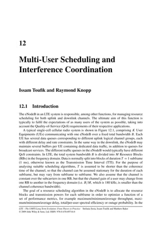


![288 LTE – THE UMTS LONG TERM EVOLUTION
meet their QoS requirements in a spectrally-efficient way. The details of this process are not
standardized as it is largely internal to the eNodeB, allowing for vendor-specific algorithms
to be developed which can be optimized for specific scenarios in conjunction with network
operators. However, the key inputs available to the resource scheduling process are common,
and in general some typical approaches can be identified.
Two extremes of scheduling algorithm may be identified: opportunistic scheduling and
fair scheduling. The former is typically designed to maximize the sum of the transmitted
data rates to all users by exploiting the fact that different users experience different channel
gains and hence will experience good channel conditions at different times and frequencies.
A fundamental characteristic of mobile radio channels is the fading effects arising from
the mobility of the UEs in a multipath propagation environment, and from variations in
the surrounding environment itself (see Chapter 21). In [1–3] it is shown that, for a multi-
user system, significantly more information can be transmitted across a fading channel than
a non-fading channel for the same average signal power at the receiver. This principle is
known as multi-user diversity. With proper dynamic scheduling, allocating the channel at
each given time instant only to the user with the best channel condition in a particular part
of the spectrum can yield a considerable increase in the total throughput as the number of
active users becomes large. In general this result relies on being able to adapt the power
dynamically according to the channel state, but it has also been shown that the greater part
of the performance gains can be achieved by an ‘on–off’ power allocation between RBs (i.e.
equal power in those RBs in which a transmission takes place). This not only allows some
simplification of the scheduling algorithm but also is well suited to a downlink scenario
where the frequency-domain dynamic range of the transmitted power in a given subframe is
limited by constraints such as the dynamic range of the UE receivers and the need to transmit
wideband reference signals for channel estimation.
The main issue arising from opportunistic resource allocation schemes is the difficulty of
ensuring fairness and QoS. Users’ data cannot always wait until the channel conditions are
sufficiently favourable for transmission, especially in slowly varying channels. Furthermore,
as explained in Chapter 1, it is important that network operators can provide reliable wide
area coverage, including to stationary users near the cell edge – not just to the users which
happen to experience good channel conditions by virtue of their proximity to the eNodeB.
The second extreme of scheduling algorithm, fair scheduling, therefore pays more
attention to latency for each user than to the total data rate achieved. This is particularly
important for real-time applications such as Voice-over-IP (VoIP) or video-conferencing,
where a certain minimum rate must be guaranteed independently of the channel state.
In practice, most scheduling algorithms fall between the two extremes outlined above,
including elements of each to deliver the required mix of QoS. When considering the degree
of fairness provided by a scheduling algorithm, a metric based on the Cumulative Density
Function (CDF) of the throughput of all users is often used. A typical example is to ensure
that the CDF of the throughput lies to the right-hand side of a particular line, such as that
shown in Figure 12.3. The objective of such a metric is to avoid heavily penalizing the cell-
edge users in order to give high throughputs to the users with good channel conditions. Other
factors also need to be taken into account, especially the fact that, in a coordinated deploy-
ment, individual cells cannot be considered in isolation – nor even the individual set of cells
controlled by a single eNodeB. The eNodeBs should take into account the interference gener-
ated by co-channel cells, which can be a severe limiting factor, especially for cell-edge users.](https://image.slidesharecdn.com/ltefromtheorytopractise-240124145854-b0067765/85/LTE_from_Theory_to_Practise-pdf-314-320.jpg)

![290 LTE – THE UMTS LONG TERM EVOLUTION
12.3.1 Ergodic Capacity
The ergodic capacity (also known as the Shannon capacity) is defined as the maximum data
rate which can be sent over the channel with asymptotically small error probability, averaged
over the fading process. When Channel State Information is available at the Transmitter
(CSIT), the transmit power and mutual information2 between the transmitter and the receiver
can be varied depending on the fading state in order to maximize the average rates. The
ergodic capacity metric considers the long-term average data rate which can be delivered to
a user when the user does not have any latency constraints.
12.3.1.1 Maximum Rate Scheduling
It has been shown in [3, 4] that the maximum total ergodic sum rate
K
k=1 Rk, where Rk is
the total rate allocated to user k, is achieved with a transmission power given by
Pk(m, f ) =
1
λk
−
N0
|Hk(m, f )|2
+
if |Hk(m, f )|2 ≥
λk
λk
|Hk (m, f )|2
0 otherwise
(12.1)
where [x]+ = max(0, x), Hk(m, f ) is the channel gain of user k in RB m of subframe f and
λk are constants which are chosen in order to satisfy an average per-user power constraint.
This approach is known in the literature as maximum rate scheduling. The result in
Equation (12.1) shows that the maximum sum rate is achieved by orthogonal multiplexing
where in each subchannel (i.e. each RB in LTE) only the user with the best channel
gain is scheduled. This orthogonal scheduling property is in line with, and thus justifies,
the philosophy of the LTE multiple-access schemes. The input power spectra given by
Equation (12.1) are water-filling formulae in both frequency and time (i.e. allocating more
power to a scheduled user when his channel gain is high and less power when it is low).3
A variant of this resource allocation strategy with no power control (relevant for cases
where the power control dynamic range is limited or zero) is considered in [2]. This allocation
strategy is called ‘maximum-rate constant-power’ scheduling, where only the user with the
best channel gain is scheduled in each RB, but with no adaptation of the transmit power. It is
shown in [2] that most of the performance gains offered by the maximum rate allocation in
Equation (12.1) are due to multi-user diversity and not to power control, so an on–off power
allocation can achieve comparable performance to maximum-rate scheduling.
12.3.1.2 Proportional Fair Scheduling
The ergodic sum rate corresponds to the optimal rate for traffic which has no delay constraint.
This results in an unfair sharing of the channel resources. When the QoS required by the
application includes latency constraints, such a scheduling strategy is not suitable and other
fairer approaches need to be considered. One such approach is the well-known Proportional
Fair Scheduling (PFS) algorithm. PFS schedules a user when its instantaneous channel
2The mutual information of two random variables is a quantity that measures the mutual dependence of the two
variables.
3Water-filling strategies are discussed in more detail in the context of MIMO in Section 11.1.3.](https://image.slidesharecdn.com/ltefromtheorytopractise-240124145854-b0067765/85/LTE_from_Theory_to_Practise-pdf-316-320.jpg)
![MULTI-USER SCHEDULING AND INTERFERENCE COORDINATION 291
quality is high relative to its own average channel condition over time. It allocates user k
in RB m in any given subframe f if k = k̂m, where [5]
k̂m = argmax
k=1,...,K
Rk (m, f )
Tk (f )
(12.2)
where Tk(f ) denotes the long-term average throughput of user k computed in subframe f
and Rk(m, f ) = log[1 + SNRk(m, f )] is the achievable rate by user k in RB m and subframe
f . The long-term average user throughputs are recursively computed by
Tk(f ) =
1 −
1
tc
Tk(f − 1) +
1
tc
M
m=1
Rk(m, f )I{k̂m = k} (12.3)
where tc is the time window over which fairness is imposed and I{·} is the indicator function
equal to one if k̂m = k and zero otherwise. A large time window tc tends to maximize the total
average throughput; in fact, in the limit of a very long time window, PFS and maximum-rate
constant-power scheduling result in the same allocation of resources. For small tc, the PFS
tends towards a round-robin4 scheduling of users in the system [5].
Several studies of PFS have been conducted in the case of WCDMA/HSDPA, yielding
insights which can be applied to LTE. In [6] the link level system performance of PFS is
studied, taking into account issues such as link adaptation dynamic range, power and code
resources, convergence settings, signalling overhead and code multiplexing. [7] analyses the
performance of PFS in the case of VoIP, including a comparison to round-robin scheduling
for different delay budgets and packet-scheduling settings. A study of PFS performance in
the case of video streaming in HSDPA can be found in [8].
12.3.2 Delay-Limited Capacity
Even though PFS introduces some fairness into the system, this form of fairness may not
be sufficient for applications which have a very tight latency constraint. For these cases, a
different capacity metric is needed; one such example is referred to as the ‘delay-limited
capacity’. The delay-limited capacity (also known as zero-outage capacity) is defined as
the transmission rate which can be guaranteed in all fading states under finite long-term
power constraints. In contrast to the ergodic capacity, where mutual information between
the transmitter and the receiver vary with the channel, the powers in delay-limited capacity
are coordinated between users and RBs with the objective of maintaining constant mutual
information independently of fading states. The delay-limited capacity is relevant to traffic
classes where a given data rate must be guaranteed throughout the connection time, regardless
of the fading dips.
The delay-limited capacity for a flat-fading multiple-access channel is characterized in [9].
The wideband case is analysed in [5,10].
It is shown in [5] that guaranteeing a delay-limited rate incurs only a small throughput
loss in high Signal-to-Noise Ratio (SNR) conditions, provided that the number of users is
large. However, the solution to achieve the delay-limited capacity requires non-orthogonal
scheduling of the users, with successive decoding in each RB. This makes this approach
basically unsuitable for LTE.
4A round-robin approach schedules each user in turn, irrespective of their prevailing channel conditions.](https://image.slidesharecdn.com/ltefromtheorytopractise-240124145854-b0067765/85/LTE_from_Theory_to_Practise-pdf-317-320.jpg)
![292 LTE – THE UMTS LONG TERM EVOLUTION
e
(bps/Hz)
Ergodic sum-rate max
Optimal Delay-Limited
Orthogonal Delay-Limited
M Mi
raged
rate
Max-Min
Aver
Number of subchannels
Figure 12.4 Comparison of scheduling algorithm performance. (Average SINR = 0 dB for
all users.)
It is, however, possible to combine orthogonal multiple access with hard QoS require-
ments.
One such scheme is known as ‘orthogonal delay-limited rate allocation’. The objective
of this strategy, as for delay-limited capacity, is to find the allocation of users to RBs which
maximizes the number of served users for a given total transmit power while achieving a
target rate-tuple R∗ = (R∗
1, R∗
2, . . . , R∗
K) through an orthogonal multiplexing of the users.
The optimal solution to this problem uses power adaptation across the RBs.
Another possibility is the Max-Min allocation. This policy guarantees that, at any given
time instant, the minimum channel gain of any of the allocated users is the highest possible
among all possible allocations and thus maximizes the minimum allocated rate when an equal
and fixed power is used for all users. This is particularly relevant for systems where no power
control (or a limited amount of power control, as in the LTE downlink) can be used.
Scheduling algorithms satisfying the two above-mentioned allocation strategies can be
found in [10,11], where the performance is compared to both optimal ergodic sum-rate and
non-orthogonal optimal delay-limited rate allocations.
12.3.3 Performance of Scheduling Strategies
Figure 12.4 shows the system spectral efficiency for each of the different allocation strategies
presented above, as a function of the number of RBs (under the assumption that the number
of UEs is always at least equal to the number of RBs).](https://image.slidesharecdn.com/ltefromtheorytopractise-240124145854-b0067765/85/LTE_from_Theory_to_Practise-pdf-318-320.jpg)
![MULTI-USER SCHEDULING AND INTERFERENCE COORDINATION 293
The curves ‘Optimal Delay-Limited’ and ‘Orthogonal Delay-Limited’ represent the
maximum achievable common rate (equal rate for all users) under optimal and orthogonal
multiple access respectively. The results in Figure 12.4 are obtained for an average Signal
to Interference plus Noise Ratio (SINR) of 0 dB for all UEs, and Rayleigh fading with
uncorrelated channel gains between RBs. Although unrealistic, this provides an idea of the
achievable rates, as a function of the approximate number of degrees of freedom allowed by
the system bandwidth and the propagation environment.
In all cases, it can be seen from Figure 12.4 that the per-user average throughput increases
with the number of users, which proves that, even under delay-limited requirements, high
multi-user diversity gains can still be achieved. It can be seen that even under hard fairness
constraints it is possible to achieve performance which is very close to the optimal unfair
policy; thus hard fairness constraints do not necessarily introduce a significant throughput
degradation, even with orthogonal resource allocation, provided that the number of users and
the system bandwidth are large. This may be a relevant scenario for a deployment targeting
VoIP users, where densities of several hundred users per cell are foreseen (as mentioned
in Section 1.2), with a latency constraint typically requiring each packet to be successfully
delivered within 50 ms. In the case of users at different distances from the eNodeB (and
hence with different SINR statistics), it has been shown in [5] that, for a high SINR scenario,
PFS does not provide any significant gain and may even perform worse than the optimal
non-orthogonal delay-limited scheduling; this is despite the fact that the imposed fairness
constraint is less stringent. However, for low to moderate SINR, the stricter hard-fairness
constraint incurs a large throughput penalty for delay-limited scheduling with respect to PFS.
The summary of scheduling strategies presented above assumes that all users have an
equal and infinite queue length – often referred to as a full-buffer traffic model. In practice
this is not the case, especially for real-time services, and information on users’ queue lengths
is necessary to guarantee system stability. If a scheduling algorithm can be found which keeps
the average queue length bounded, the system is said to be stabilized [12]. One approach
to ensuring that the queue length remains bounded is to use the queue length to set the
priority order in the allocation of RBs. This generally works for lightly-loaded systems.
References [13] and [14] show that in wideband frequency-selective channels, low average
packet delay can be achieved even if the fading is very slow.
12.4 Considerations for Resource Scheduling in LTE
In LTE, each logical channel has a corresponding QoS description which should influence the
behaviour of the eNodeB resource scheduling algorithm. Based on the evolution of the radio
and traffic conditions, this QoS description could potentially be updated for each service in
a long-term fashion. It is likely that the mapping between the QoS descriptions of different
services and the resource scheduling algorithm in the eNodeB will be a key differentiating
factor between radio network equipment manufacturers.
An important constraint for the eNodeB scheduling algorithm is the availability and
accuracy of the channel quality information for the active UEs in the cell. The manner in
which such information is provided to the scheduler in LTE differs between uplink and
downlink transmissions. In practice, for the downlink this information is provided through
the feedback of Channel Quality Indicators (CQIs) by UEs as described in Chapter 10, while](https://image.slidesharecdn.com/ltefromtheorytopractise-240124145854-b0067765/85/LTE_from_Theory_to_Practise-pdf-319-320.jpg)

![MULTI-USER SCHEDULING AND INTERFERENCE COORDINATION 295
where Hs
k (m, f ) is the channel gain from the serving cell s to user k, Ps(m, f ) is the transmit
power from cell s and N0 is the noise power. If neighbouring cells are transmitting in the same
time-frequency resources, then the achievable rate for user k reduces to
Rk,Int(m, f ) =
B
M
log 1 +
Ps(m, f )|Hs
k (m, f )|2
N0 +
i=s Pi(m, f )|Hi
k(m, f )|2
(12.5)
where the indices i denote interfering cells.
The rate loss for user k can then be expressed as
Rk,loss(m, f ) = Rk,no-Int(m, f ) − Rk,Int(m, f )
=
B
M
log
1 + SNR
1 +
,
1
SNR +
i=s Pi(m,f )|Hi
k(m,f )|2
Ps (m,f )|Hs
k (m,f )|2
-−1
(12.6)
Figure 12.5 plots the rate loss for user k as a function of the total inter-cell interference
to signal ratio α = [(
i=s Pi (m, f )|Hi
k(m, f )|2)/(Ps(m, f )|Hs
k (m, f )|2)], with SNR =
0 dB. It can easily be seen that for a level of interference equal to the desired signal level (i.e.
α ≈ 0 dB), user k experiences a rate loss of approximately 40%.
In order to demonstrate further the significance of interference and power allocation
depending on the system configuration we consider two examples of a cellular system with
two cells (s1 and s2) and one active user per cell (k1 and k2 respectively). Each user receives
the wanted signal from its serving cell, while the inter-cell interference comes from the other
cell.
In the first example, each user is located near its respective eNodeB (see Figure 12.6(a)).
The channel gain from the interfering cell is small compared to the channel gain from the
serving cell (|H
s1
k1
(m, f )| |H
s2
k1
(m, f )| and |H
s2
k2
(m, f )| |H
s1
k2
(m, f )|). In the second
example (see Figure 12.6(b)), we consider the same scenario but with the users now located
close to the edge of their respective cells. In this case the channel gain from the serving
cell and the interfering cell are comparable (|Hs1
k1
(m, f )| ≈ |Hs2
k1
(m, f )| and |Hs2
k2
(m, f )| ≈
|Hs1
k2
(m, f )|).
The capacity of the system with two eNodeBs and two users can be written as
RTot =
B
M
log
1 +
Ps1 |Hs1
k1
(m, f )|2
N0 + Ps2 |Hs2
k1
(m, f )|2
+ log
1 +
Ps2 |Hs2
k2
(m, f )|2
N0 + Ps1 |Hs1
k2
(m, f )|2
(12.7)
From this equation, it can be noted that the optimal transmit power operating point in terms
of maximum achievable throughput is different for the two considered cases. In the first
scenario, the maximum throughput is achieved when both eNodeBs transmit at maximum
power, while in the second the maximum capacity is reached by allowing only one eNodeB
to transmit. It can in fact be shown that the optimal power allocation for maximum capacity
for this situation with two base stations is binary in the general case; this means that either
both base stations should be operating at maximum power in a given RB, or one of them
should be turned off completely in that RB [15].
From a practical point of view, this result can be exploited in the eNodeB scheduler by
treating users in different ways depending on whether they are cell-centre or cell-edge users.](https://image.slidesharecdn.com/ltefromtheorytopractise-240124145854-b0067765/85/LTE_from_Theory_to_Practise-pdf-321-320.jpg)
![296 LTE – THE UMTS LONG TERM EVOLUTION
−10 −8 −6 −4 −2 0 2 4 6 8 10
0
10
20
30
40
50
60
70
80
90
α (dB)
rate
loss
(in
%)
Figure 12.5 User’s rate loss due to interference.
Each cell can then be divided into two parts – inner and outer. In the inner part, where
users experience a low level of interference and also require less power to communicate with
the serving cell, a frequency reuse factor of 1 can be adopted. For the outer part, scheduling
restrictions are applied: when the cell schedules a user in a given part of band, the system
capacity is optimized if the neighbouring cells do not transmit at all; alternatively, they may
transmit only at low power (probably to users in the inner parts of the neighbouring cells) to
avoid creating strong interference to the scheduled user in the first cell. This effectively results
in a higher frequency reuse factor at the cell-edge; it is often known as ‘partial frequency
reuse’, and is illustrated in Figure 12.7.
In order to coordinate the scheduling in different cells in such a way, communication
between neighbouring cells is required. If the neighbouring cells are managed by the
same eNodeB, a coordinated scheduling strategy can be followed without the need for
standardized signalling. However, where neighbouring cells are controlled by different
eNodeBs, standardized signalling is important, especially in multivendor networks. Inter-Cell
Interference Coordination (ICIC) in LTE is normally assumed to be managed in the frequency
domain rather than the time domain (as time domain coordination would interfere with the
operation of the HARQ processes, especially in the uplink where synchronous HARQ is
used), and the inter-eNodeB signalling is designed to support this.
In relation to the downlink transmissions, a bitmap termed the Relative Narrowband
Transmit Power (RNTP5) indicator can be exchanged between eNodeBs over the X2
interface. Each bit of the RNTP indicator corresponds to one RB in the frequency domain
and is used to inform the neighbouring eNodeBs if a cell is planning to keep the transmit
5RNTP is defined in reference [16], Section 5.2.1.](https://image.slidesharecdn.com/ltefromtheorytopractise-240124145854-b0067765/85/LTE_from_Theory_to_Practise-pdf-322-320.jpg)

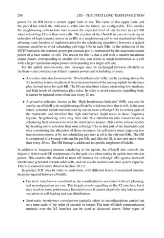
![MULTI-USER SCHEDULING AND INTERFERENCE COORDINATION 299
information such as traffic load information may also be used, as discussed in
Section 2.6.4. Semi-static interference coordination may be more beneficial in cases of
non-uniform load distributions in eNodeBs and varying cell sizes across the network.
12.6 Concluding Remarks
In summary, it can be observed that a variety of resource scheduling algorithms may be
applied by the eNodeB depending on the optimization criteria required. The prioritization
of data will typically take into account the corresponding traffic classes, especially in regard
to balancing throughput maximization for delay-tolerant applications against QoS for delay-
limited applications in a fair way.
It can be seen that multi-user diversity is an important factor in all cases, and especially
if the user density is high, in which case the multi-user diversity gain enables the scheduler
to achieve a high capacity even with tight delay constraints. Finally, it is important to note
that individual cells, and even individual eNodeBs, cannot be considered in isolation. System
optimization requires some degree of coordination between cells and eNodeBs, in order to
avoid inter-cell interference becoming the limiting factor. Considering the system as a whole,
the best results are in many cases realized by simple ‘on–off’ allocation of resource blocks,
whereby some eNodeBs avoid scheduling transmissions in certain resource blocks which are
used by neighbouring eNodeBs for cell-edge users.
References6
[1] K. Knopp and P. A. Humblet, ‘Information Capacity and Power Control in Single-cell Multiuser
Communications’, in Proc. IEEE International Conference on Communications, Seattle, WA,
1995.
[2] R. Knopp and P. A. Humblet, ‘Multiple-Accessing over Frequency-selective Fading Channels’,
in Proc. IEEE International Symposium on Personal, Indoor and Mobile Radio Communications,
September 1995.
[3] D. N. C. Tse and S. D. Hanly, ‘Multiaccess Fading Channels. I: Polymatroid Structure, Optimal
Resource Allocation and Throughput Capacities’. IEEE Trans. on Information Theory, Vol. 44,
pp. 2796–2815, November 1998.
[4] R. Knopp and P. A. Hamblet, ‘Multiuser Diversity’, Technical Report, Eurecom Institute, Sophia
Antipolis, France, 2002.
[5] G. Caire, R. Müller, and R. Knopp, ‘Hard Fairness Versus Proportional Fairness in Wireless
Communications: The Single-cell Case’. IEEE Trans. on Information Theory, Vol. 53, pp. 1366–
1385, April 2007.
[6] T. E. Kolding, ‘Link and System Performance Aspects of Proportional Fair Scheduling in
WCDMA/HSDPA’, in Proc. IEEE Vehicular Technology Conference, Orlando, FL, October 2003.
[7] B. Wang, K. I. Pedersen, P. E. Kolding and T. E. Mogensen, ‘Performance of VoIP on HSDPA’,
in Proc. IEEE Vehicular Technology Conference, Stockholm, May 2005.
[8] V. Vukadinovic and G. Karlsson, ‘Video Streaming in 3.5G: On Throughput-Delay Performance
of Proportional Fair Scheduling’, in IEEE International Symposium on Modeling, Analysis, and
Simulation of Computer and Telecommunication Systems, Monterey, CA, September 2006.
6All web sites confirmed 18th December 2008.](https://image.slidesharecdn.com/ltefromtheorytopractise-240124145854-b0067765/85/LTE_from_Theory_to_Practise-pdf-325-320.jpg)
![300 LTE – THE UMTS LONG TERM EVOLUTION
[9] S. D. Hanly and D. N. C. Tse, ‘Multiaccess Fading Channels. II: Delay-limited Capacities’. IEEE
Trans. on Information Theory, Vol. 44, pp. 2816–2831, November 1998.
[10] I. Toufik, ‘Wideband Resource Allocation for Future Cellular Networks’. Ph.D. Thesis, Eurecom
Institute, 2006.
[11] I. Toufik and R. Knopp, ‘Channel Allocation Algorithms for Multi-carrier Systems’, in Proc.
IEEE Vehicular Technology Conference, Los Angeles, CA, September 2004.
[12] M. J. Neely, E. Modiano and C. E. Rohrs, ‘Power Allocation and Routing in Multi-beam Satellites
with Time Varying Channels’. IEEE Trans. on Networking, Vol. 11, pp. 138–152, February 2003.
[13] M. Realp, A. I. Pérez-Neira and R. Knopp, ‘Delay Bounds for Resource Allocation in Wideband
Wireless Systems’, in Proc. IEEE International Conference on Communications, Istanbul, June
2006.
[14] M. Realp, R. Knopp and A. I. Pérez-Neira, ‘Resource Allocation in Wideband Wireless Systems’
in Proc. IEEE International Symposium on Personal, Indoor and Mobile Radio Communications,
Berlin, September 2005.
[15] A. Gjendemsjoe, D. Gesbert, G. Oien and S. Kiani, ‘Binary Power Control for Sum Rate
Maximization over Multiple Interfering Links’. IEEE Trans. Wireless Communications, August
2008.
[16] 3GPP Technical Specification 36.213, ‘Evolved Universal Terrestrial Radio Access (E-UTRA);
Physical Layer Procedures (Release 8)’, www.3gpp.org.](https://image.slidesharecdn.com/ltefromtheorytopractise-240124145854-b0067765/85/LTE_from_Theory_to_Practise-pdf-326-320.jpg)

![302 LTE – THE UMTS LONG TERM EVOLUTION
13.2 Overview of UE Mobility Activities
In order to maintain service continuity as a user moves, UEs must not only be connected
to a serving cell but importantly also monitor their neighbour cells. This monitoring is an
ongoing activity, since propagation conditions to different eNodeBs can change rapidly at
any point in time, as can interference levels. Typically the efforts by the UE and the network
will always be directed towards providing service continuity on a preferred RAT according
to a given preference criterion which may for example include Quality of Service (QoS), cost
or network operator.
Generally while a UE has service with its preferred network, it will be requested to
perform mobility decisions (handover or cell reselection) towards other base stations from
the same RAT. Whenever the preferred network is not available because of poor coverage,
congestion or other reasons, the network and the UE must cooperate in order to identify
fallback options to other networks or RATs to preserve service continuity. A fallback RAT
may in some cases only be able to provide a subset of more basic services (e.g. voice
communications or low data rate packet data), thus resulting in some degradation in terms of
the services provided, but at least basic service continuity can be preserved.
Mobility procedures have to be specified for a significant number of different possible
scenarios, and these are described in detail in the following sections. In all cases the UE has to
meet specified minimum performance requirements which are scenario-specific, such as for
cell search (see Chapter 7), measurement accuracy, measurement periodicity and handover
execution delay. UE power consumption and cost are also important factors, and for this
reason the procedures and requirements are generally specified so as to minimize the effort
required from the UE. These requirements are mainly specified in [1]. The performance
requirements for mobility are usually specific to a particular scenario, consisting of:
• The current serving RAT.
• The Layer 3 state of the current serving RAT, e.g. for LTE the main Radio Resource
Control (RRC) states are RRC_CONNECTED and RRC_IDLE (see Section 3.2.1).
• The RAT being monitored. When camped on an LTE cell a UE needs to monitor other
cells on the same LTE frequency (LTE intra-frequency cells) and cells on other LTE
frequencies (LTE inter-frequency cells). In addition it may be required to monitor one
or more other RATs, such as GSM, UMTS, WiMAX, TD-SCDMA, CDMA High Rate
Packet Data (HRPD), or CDMA2000. The performance requirements in each case
depend on the RAT being monitored.
In the case of the 3GPP RATs (i.e. LTE, UMTS and GERAN1), the minimum-effort
approach for the UE typically consists of a number of common stages which are broadly
the same regardless of the RAT involved. Each of these common stages constitutes a decision
point, either in the UE or in the network. These stages are:
• Serving cell quality monitoring and evaluation. Serving cell quality is monitored
and evaluated on a periodic basis. If the serving cell quality is satisfactory (i.e. above
a threshold which is configurable by the network), then no further action is required.
1GSM EDGE Radio Access Network.](https://image.slidesharecdn.com/ltefromtheorytopractise-240124145854-b0067765/85/LTE_from_Theory_to_Practise-pdf-328-320.jpg)

![304 LTE – THE UMTS LONG TERM EVOLUTION
• Primary Synchronization Signal (PSS) detection to obtain the physical layer cell ID
(within a group of three) and slot synchronization.
• Secondary Synchronization Signal (SSS) detection to obtain the Cyclic Prefix (CP)
length, the physical layer cell group ID and the frame synchronization.
• Physical Broadcast CHannel (PBCH) decoding to obtain the critical system informa-
tion and the 40 ms period of the system information. For new cell identification, PBCH
decoding is not required but Reference Signal (RS) decoding may be performed to
measure the RSRP and the Reference Signal Received Quality (RSRQ)2 of the new
cell to be reported to the network.
13.3.2 UMTS Cell Search
UMTS synchronization codes are defined in [2] and an overview is provided in [3]. A UE is
synchronized to a UMTS cell when it knows the timing of the cell’s frame boundaries and
the identity of the cell’s primary scrambling code which distinguishes the cell’s transmissions
from those of other cells. The most common UMTS synchronization process consists of the
following stages:
• Primary-Synchronization CHannel (P-SCH) search. Only one UMTS P-SCH code
exists, and it is repeated on the first 256 chips of every slot (0.666 ms) in all UMTS
cells. During this stage the UE performs matched filter correlation between the received
signal and the P-SCH sequence. These correlations are performed for all possible
timing offsets within one slot. As a result a curve containing P-SCH correlation power
as a function of the time offset can be obtained and correlation peaks can be observed
in those locations where a P-SCH sequence is present. This gives the slot boundary
timing for each detected P-SCH. For one or more of the strongest detected peaks, the
following step is performed.
• Secondary-SCH decoding. The UTRA S-SCH code sequence in a cell is one of 15
codewords present on the first 256 chips of every slot (i.e. at the same time as the P-
SCH). One S-SCH code sequence is defined for all cells belonging to the same ‘code
group’. Each S-SCH code sequence identifies uniquely a code group and 10 ms frame
boundary position. In good signal conditions the information contained within three
slots is sufficient to identify uniquely both the frame timing and the code group, but in
order to reliably decode the S-SCH in difficult reception conditions longer decoding
periods are required.
• Primary scrambling code identification. The code group identified from the S-SCH
indicates a group of eight primary scrambling codes. A given cell uses one code from
the indicated group as the scrambling code for all downlink channels, including the
Primary Common PIlot CHannel (P-CPICH). In order to determine which code is
being used, the UE performs a simple correlation against the eight possible scrambling
sequences in the code group, looking for the known CPICH sequence (which is the
same in all UMTS cells).
2Refer to Section 13.4 for more details on RSRP and RSRQ measurements.](https://image.slidesharecdn.com/ltefromtheorytopractise-240124145854-b0067765/85/LTE_from_Theory_to_Practise-pdf-330-320.jpg)
![RADIO RESOURCE MANAGEMENT 305
• UMTS System Frame Number (SFN) detection. The UMTS Primary Common
Control Physical CHannel (P-CCPCH) carries the Broadcast CHannel (BCH), which
is encoded over a 20 ms Transmission Time Interval (TTI). However, the earlier
synchronization stages only provide timing information up to a 10 ms period (i.e. one
UMTS frame). The location of the even frame boundaries can be found, for example,
by trial and error by performing decoding attempts on the two possible TTI boundaries.
Only the correct boundary will lead to successful channel decoding and return a correct
Cyclic Redundancy Check (CRC). The BCH payload carries the SFN. This step is only
required in some inter-RAT scenarios: on cell reselection from LTE to UMTS and on
handover to UMTS (only after handover initiation).
It is worth noting that once a UE has camped on an LTE cell it will receive a UMTS
neighbour cell list containing up to 32 primary scrambling codes per UMTS carrier. This
additional side information may be used by the UE to speed up the UMTS cell search process.
13.3.3 GSM Cell Search
Typically the synchronization process to a GSM cell consists of: GSM Received Signal
Strength Indicator (RSSI) measurements, initial Base Station Identification Code (BSIC)
identification and BSIC reconfirmation.
These synchronization stages are briefly described in the subsections below. A more
extensive description of the GSM common channels is provided in [4]. When camped on
an LTE cell the UE will be provided with a Neighbour Cell List (NCL) containing at least
32 GSM carrier numbers (i.e. Absolute Radio Frequency Channel Numbers (ARFCNs))
indicating the frequencies of neighbouring cells, and optionally an associated BSIC for each
GSM carrier in the NCL.
13.3.3.1 GSM RSSI Measurements
When GSM monitoring is required, a UE will measure GSM RSSI for all the carriers in the
NCL in every measurement period configured by the network. Once measurements for all the
cells in the list have become available, the results are sorted in order of decreasing power, and
the strongest N cells are passed to the following step. The GSM RSSI measurement period is
480 ms, and any GSM RSSI measurement must be the average of at least three measurement
samples as evenly spaced as possible.
13.3.3.2 Initial BSIC Identification
The BSIC is contained within the GSM Synchronization Burst (SB), which carries the
GSM Synchronization CHannel (SCH). In addition to the BSIC, the GSM SCH also carries
information related to the GSM cell SFN. The BSIC allows a UE to distinguish two different
GSM cells which share the same beacon frequency. It is a 6-bit field composed of two 3-
bit fields: the Base station Colour Code (BCC) and the Network Colour Code (NCC). The
BCC is also used to identify the Training Sequence Code (TSC) to be used when reading the
Broadcast Control CHannel (BCCH). The NCC is used to differentiate between operators
utilizing the same frequencies, e.g. on an international border when both operators have been
allocated the same frequency or frequencies.](https://image.slidesharecdn.com/ltefromtheorytopractise-240124145854-b0067765/85/LTE_from_Theory_to_Practise-pdf-331-320.jpg)
![306 LTE – THE UMTS LONG TERM EVOLUTION
Initial BSIC identification is performed in order of decreasing power for the N = 8
strongest GSM carriers. Typically, initial BSIC Identification in a UE consists of the
following steps:
• GSM Frequency Control Channel (FCCH) detection. In order to detect a Frequency
Burst (FB) carried by the GSM FCCH, the UE must tune its receiver to a GSM beacon
carrier frequency and perform a continuous correlation against the signal contained
within the FB. The FB is transmitted on timeslot number 0 of frames 0, 10, 20, 30
and 40 of the 51-frame GSM control multiframe, as depicted in Figure 13.1. When a
correlation peak is detected, coarse frame timing and coarse frequency synchronization
can be acquired. Note that if continuous correlation is performed, the GSM FCCH is
guaranteed to be detected under good reception conditions in no more than 11 GSM
frames. One GSM frame has a duration equal to 60/13 = 4.61 ms.
• GSM SCH detection. The GSM SB is carried by the GSM SCH. There is always one
SB exactly one frame after the FB. GSM SCH decoding is reasonably straightforward
when it is possible to receive the SB exactly one frame after FB detection. If decoding
the SB immediately after the FB is not an option, for example because initial BSIC
identification is being performed within a gap in the LTE signal specially created for
inter-RAT monitoring and this gap is too short, then the GSM SCH can be decoded
later. In that case the task of decoding the GSM SCH becomes more complicated
because of the presence of the GSM idle frame in the 51-frame control multiframe. The
idle frame introduces a N/(N + 1) frame ambiguity which forces the UE to perform
decoding attempts at two adjacent locations after FB detection separated by one GSM
frame: 10/11 frames, 20/21 frames, etc. as can be seen from Figure 13.1. Given that
the data carried in the SCH contains a CRC, the outcome of the CRC check can be
used to determine which of the two options is the correct outcome. Once the SCH has
been successfully decoded, both the BSIC and the GSM frame number are obtained,
and the position of any GSM SB can be predicted without any further ambiguity.
F S F S F S
F S I
I F S
Idle frame FCCH SCH
F S
Figure 13.1 GSM common control channel structure. Each square represents the contents of
slot 0 for each GSM frame within the 51-frame control multiframe.
It is also possible to detect directly the GSM SCH without prior FCCH detection.
However, this involves additional complexity, and the additional benefits in term of detection
performance (delay and sensitivity) may not be sufficiently significant to justify this. Initial
BSIC identification requirements from UMTS in [5] allow for the implementation of the 2-
steps approach. It is very likely that the same requirements will be adopted in [1] for LTE.](https://image.slidesharecdn.com/ltefromtheorytopractise-240124145854-b0067765/85/LTE_from_Theory_to_Practise-pdf-332-320.jpg)
![RADIO RESOURCE MANAGEMENT 307
13.3.3.3 BSIC Reconfirmation
BSIC Reconfirmation consists of decoding the SB periodically on GSM carriers for which the
BSIC has already been detected by initial BSIC identification. In this situation the SB position
within a cell can be predicted exactly because the neighbour cell SFN has been acquired by
the UE in the previous step. The UE needs to check periodically that the carrier for which the
BSIC was previously identified still has the same BSIC because GSM beacon channels can
be reused. In addition, 3GPP base stations are not synchronized, and BSIC reconfirmation
attempts can also be used to perform minor adjustments to the GSM cell timing stored in the
UE, to compensate for cell timing drift relative to the serving cell to which the UE is locked.
After a number of unsuccessful BSIC reconfirmation attempts a GSM carrier must be moved
back to initial BSIC identification.
13.4 Measurements when Camped on LTE
A UE camped on an LTE cell must be able to perform the measurements described in this
section (see [6] for further details).
The majority of UE physical layer measurements require some degree of coherent
demodulation3 and processing. Therefore, these measurements can only be performed after
the UE has achieved synchronization with the target cell and knows the relevant physical
layer parameters which are required in order to perform coherent processing; this includes
the slot timing, frame timing and scrambling codes. There are, however, a few carrier-
specific signal strength measurements which can be performed non-coherently without
having achieved synchronization; these are LTE carrier RSSI, UMTS carrier RSSI and GSM
RSSI (see Sections 13.4.1.2, 13.4.2.2 and 13.4.4.1 respectively).
All measurements reported from the UE by RRC signalling must be obtained by averaging
multiple measurement samples which are as uniformly distributed as possible over the
measurement period in the time domain, and over the measurement bandwidth in the
frequency domain, [1].
The actual implementation of the measurement algorithms is not specified. Any imple-
mentation is possible as long as the associated performance requirements in [1] are met.
The measurement model adopted for LTE has been inherited from the UMTS specifica-
tions [5,7]. The model contains four different reference points as shown in Figure 13.2.
• Reference point ‘A’ represents a measurement internal to the physical layer (‘Layer 1’)
in support of the measurements to be provided to higher layers. An example could be
a single measurement sample of LTE RSRP corresponding to a very short integration
time (e.g. 1 ms). The actual measurement implementation is not constrained by the
LTE specifications, but the expected value measurements obtained must correspond to
the measurement definition in reference [6].
• Reference point ‘B’ represents measurements after Layer 1 filtering being reported to
RRC (‘Layer 3’). The actual measurement is not constrained by the specifications –
i.e. the model does not state a specific sampling rate, nor even whether the sampling
is periodic or not. The LTE specifications simply define the performance objective,
3See Section 7.3 for an explanation and theoretical analysis of coherent and non-coherent demodulation.](https://image.slidesharecdn.com/ltefromtheorytopractise-240124145854-b0067765/85/LTE_from_Theory_to_Practise-pdf-333-320.jpg)
![308 LTE – THE UMTS LONG TERM EVOLUTION
Layer 1
filtering
Layer 3
filtering Evaluation
of reporting
criteria
A D
B C
C’
parameters parameters
Figure 13.2 E-UTRAN measurement model. Reproduced by permission of © 3GPP.
measurement bandwidth and measurement period. The reporting rate at point B is
also not specified, but it needs to be sufficient to meet the specified performance
objectives [1]. Measurement performance at point ‘B’ can be verified by defining tests
with Layer 3 filtering disabled.
• Reference point ‘C’ represents a measurement after processing in the Layer 3 filter
in RRC. The reporting rate is identical to the reporting rate at point B and is therefore
also dependent on the measurement type. Although this is not shown in Figure 13.2,
one measurement can be used by a multiplicity of evaluations of reporting criteria in
RRC, as explained in Section 3.2.5. The behaviour of the Layer 3 filters is standardized
and their configuration is provided by RRC signalling. Each filtered result at point C
corresponds to a filtered version of the samples available at point B.
• Reference point ‘D’ contains measurement reports sent by the UE to the eNodeB
by RRC signalling. The evaluation of reporting criteria consists of checking whether
actual measurement reporting is necessary at point D, i.e. whether a message needs
to be sent over the radio interface. The evaluation can be based on more than one
flow of measurements (C, C) at reference point C, for example to compare between
different measurements. The UE evaluates the reporting criteria at least every time a
new measurement result is reported. The reporting criteria are standardized and their
configuration provided by RRC signalling [9] (see Chapter 3).
13.4.1 LTE Measurements
13.4.1.1 LTE Reference Signal Received Power (RSRP)
The RSRP measurement provides a cell-specific signal strength metric. This measurement is
used mainly to rank different LTE candidate cells according to their signal strength and is
used as an input for handover and cell reselection decisions. RSRP is defined for a specific
cell as the linear average over the power contributions (in Watts) of the Resource Elements
(REs) which carry cell-specific RS within the considered measurement frequency bandwidth.
Normally the RS transmitted on the first antenna port are used for RSRP determination, but](https://image.slidesharecdn.com/ltefromtheorytopractise-240124145854-b0067765/85/LTE_from_Theory_to_Practise-pdf-334-320.jpg)
![RADIO RESOURCE MANAGEMENT 309
the RS on the second antenna port can also be used if the UE can determine that they are
being transmitted. Details of the RS design can be found in Chapter 8. If receive diversity is
in use by the UE, the reported value is the linear average of the power values of all diversity
branches.
13.4.1.2 LTE Carrier Received Signal Strength Indicator (RSSI)
The LTE carrier RSSI is defined as the total received wideband power observed by the
UE from all sources, including co-channel serving and nonserving cells, adjacent channel
interference and thermal noise within the measurement bandwidth specified in [1]. LTE
carrier RSSI is not reported as a measurement in its own right, but is used as an input to
the LTE RSRQ measurement described below.
13.4.1.3 LTE Reference Signal Received Quality (RSRQ)
This measurement is intended to provide a cell-specific signal quality metric. Similarly to
RSRP, this metric is used mainly to rank different LTE candidate cells according to their
signal quality. This measurement is used as an input for handover and cell reselection
decisions, for example in scenarios for which RSRP measurements do not provide sufficient
information to perform reliable mobility decisions. The RSRQ is defined as the ratio
N · RSRP/(LTE carrier RSSI), where N is the number of Resource Blocks (RBs) of the LTE
carrier RSSI measurement bandwidth. The measurements in the numerator and denominator
are made over the same set of resource blocks. While RSRP is an indicator of the wanted
signal strength, RSRQ additionally takes the interference level into account due to the
inclusion of RSSI. RSRQ therefore enables the combined effect of signal strength and
interference to be reported in an efficient way [10].
13.4.2 UMTS FDD Measurements
13.4.2.1 UMTS FDD CPICH Received Signal Code Power (RSCP)
UTRA FDD CPICH RSCP is a UMTS measurement equivalent to LTE RSRP. This
measurement is used mainly to rank different UMTS FDD candidate cells according to
their signal strength and is used as an input for decisions on handover and cell reselection
to UMTS. It is defined as the received power measured on the P-CPICH [11]. If transmit
diversity is applied on the P-CPICH, the received code power from each antenna is measured
separately and summed together in Watts to a total received code power.
13.4.2.2 UMTS FDD Carrier RSSI
This measurement is defined as the received wideband power including thermal noise and
noise generated in the receiver, for the UMTS FDD carrier, within the bandwidth defined by
the receiver pulse shaping filter [11].
13.4.2.3 UMTS FDD CPICH Ec/N0
The UTRA FDD CPICH Ec/N0 measurement is defined as the received energy per chip
(Ec) on the P-CPICH of a given cell divided by the total noise power density (N0) on the](https://image.slidesharecdn.com/ltefromtheorytopractise-240124145854-b0067765/85/LTE_from_Theory_to_Practise-pdf-335-320.jpg)
![310 LTE – THE UMTS LONG TERM EVOLUTION
UMTS carrier [11]. CPICH Ec/N0 is used mainly to rank different UMTS FDD candidate
cells according to their signal quality and is used as an input for handover and cell reselection
decisions. If receive diversity is not in use by the UE, the CPICH Ec/N0 is identical to CPICH
RSCP divided by UMTS Carrier RSSI. If transmit diversity is applied on the P-CPICH the
received Ec from each antenna must be separately measured and summed together (in Watts)
to a total received energy per chip on the P-CPICH, before calculating the Ec/N0.
13.4.3 UMTS TDD Measurements
13.4.3.1 UMTS TDD Carrier RSSI
This measurement is defined as the received wideband power, including thermal noise and
noise generated in the receiver, within the bandwidth defined by the receiver pulse shaping
filter, for UMTS TDD within a specified timeslot [12].
13.4.3.2 UMTS TDD P-CCPCH RSCP
P-CCPCH RSCP is defined as the received power on the P-CCPCH of a neighbour UMTS
TDD cell. This measurement is used mainly to rank different UMTS TDD candidate cells
according to their signal strength and is used as an input for handover and cell reselection
decisions [12].
13.4.4 GSM Measurements
13.4.4.1 GSM Carrier RSSI
GSM RSSI is the wideband received power within the GSM channel bandwidth. This
measurement is performed on a GSM BCCH carrier (i.e. a beacon carrier frequency).
13.4.5 CDMA2000 Measurements
13.4.5.1 CDMA2000 1x RTT Pilot Strength
This measurement is equivalent to LTE RSRP. It is therefore used mainly to rank different
CDMA2000 1x candidate cells according to their signal strength and is used as an input for
handover and cell reselection decisions. A detailed definition can be found in [13].
13.4.5.2 CDMA2000 HRPD Pilot Strength
This measurement is equivalent to LTE RSRP. Therefore, it is used mainly to rank different
CDMA2000 HRPD candidate cells according to their signal strength and is used as an
input for handover and cell reselection decisions. The CDMA2000 HRPD pilot strength
measurement is defined in [14].](https://image.slidesharecdn.com/ltefromtheorytopractise-240124145854-b0067765/85/LTE_from_Theory_to_Practise-pdf-336-320.jpg)
![RADIO RESOURCE MANAGEMENT 311
13.5 LTE Mobility in RRC_IDLE – Neighbour Cell
Monitoring and Cell Reselection
From the protocol point of view, the handling of mobility in RRC_IDLE is explained in
Section 3.3. This section focuses on the measurement and performance aspects.
All the LTE mobility procedures in RRC_IDLE state are performed autonomously within
the UE and extreme care is taken when they are defined so that they enable sufficient
UE mobility performance without unduly constraining power-efficient UE implementations.
The detailed implementation of cell search and measurements in RRC_IDLE is therefore
deliberately not specified in significant detail in order to enable different manufacturers to
optimize their own implementations subject to meeting the specified minimum performance
requirements. There are two main drivers for the UE behaviour being autonomous. The first
is the minimization of transmission resource usage by inactive UEs. In fact, over-the-air
signalling is only required for RRC_IDLE mobility if a tracking area update is needed (see
Section 13.5.1). The second driver for autonomous UE behaviour is UE power saving.
The main objective in RRC_IDLE is to camp on a serving cell where UE paging reception
is sufficiently reliable that a UE can be paged in the event of an incoming call; UE operations
are restricted to periodic paging reception and serving cell monitoring. These are the only
activities which a UE must perform while the serving cell quality is good enough. In order
to maximize UE battery life, the UE is not required to perform any frequent neighbour cell-
monitoring activity (cell search and measurements) unless the serving quality drops below a
specified threshold. RRC_IDLE procedures are described in detail in Chapter 3 and [15], and
associated performance requirements in [1].
13.5.1 Priority-Based Cell Reselection
Priority-based cell reselection is a novel principle adopted in LTE to improve the performance
of cell reselection in the presence of multiple RATs which may coexist in the same
geographical location. This approach reduces the need for a UE to monitor all the available
intra-system frequency layers and inter-RAT carriers by monitoring them according to a set
of priority rules provided to the UE. These rules are defined in [15]. The following steps
are carried out every time a UE performs cell reselection and camps on a new cell while
in RRC_IDLE:
• Decode broadcast information. A UE decides to camp on a cell if the cell suitability
criteria (see Section 3.3) defined in [15] are met. When the UE camps on a cell it will
receive all the relevant system information broadcast on the BCH [9]. This information
includes parameters such as cell-specific configuration information (e.g. paging and
random access parameters, cell bandwidth) and configurations for RRC_IDLE mea-
surements and cell reselection (e.g. the serving cell minimum quality threshold, i.e. S-
threshold, UMTS neighbour cell list, GSM neighbour cell list). Neighbour cell priority
information is also provided to the UE through dedicated signalling (not broadcast).
• Tracking Area Update. If the UE has moved to a cell which belongs to a different
tracking area,4 it will establish a brief signalling connection with the eNodeB to inform
4A Tracking Area is a group of contiguous cells which helps to track UEs.](https://image.slidesharecdn.com/ltefromtheorytopractise-240124145854-b0067765/85/LTE_from_Theory_to_Practise-pdf-337-320.jpg)
![312 LTE – THE UMTS LONG TERM EVOLUTION
it about its new location within the new tracking area before it enters the paging
reception stage.
• Paging reception. The UE determines the paging Discontinuous Reception (DRX)
cycle and other relevant paging parameters by processing the serving cell paging
parameters broadcast by the serving cell. From this point, and unless a UE is being
paged or cell reselection occurs, the UE will periodically wake up on every paging
occasion to check for paging messages; at the same time, the UE can measure its
serving cell quality. Paging reception is explained in Section 3.4.
When the LTE serving cell signal quality is poor (e.g. below a certain RSRP threshold)
the UE risks losing service on the serving cell, and it must attempt to identify and
reselect a new suitable cell. Therefore, all possible networks need to be searched and
measured regardless of their relative priority, and the UE must camp on the highest
priority network which can be detected and meets the suitability criteria. Given that
the serving cell quality is poor and the risk of losing service is high, the search rate
will be frequent (i.e. a small multiple of the paging DRX period) [1].
If the serving cell quality is good enough, according to the S-criterion (see Section
3.3.3), then searching for lower priority layers does not need to be performed. The
UE still needs to search for cells in higher priority layers at a reduced rate compared
to the previous case and the UE must reselect a higher priority cell if it meets the
cell reselection criteria. Given that the quality of the received signal from the current
serving cell is good and the UE can be reached, the search rate can be far less frequent
in order to reduce UE power consumption (typical values under consideration are in
the order of 60 s).
• Cell reselection evaluation. On every paging occasion the cell reselection criterion
is evaluated. If a neighbour cell currently being measured meets the cell reselection
criterion then cell reselection towards that cell is initiated and the UE restarts the
process named cell-specific configuration on the new cell.
13.5.2 Measurements in Idle Mode
The UE neighbour cell search, measurement rates and reselection evaluation rates are a
function of the paging DRX cycle which has been configured, of the layer being measured
(cell search and measurement rates tend to be higher for LTE intra-frequency cells, followed
by LTE inter-frequency cells and inter-RAT cells) and a function of whether or not the serving
cell quality is above a configured threshold. If the serving cell quality is poor, measurement
of neighbour cells is relatively frequent (typically a small multiple of a DRX cycle). If the
serving cell received quality is good then measurement rates can be far lower.
13.6 LTE Mobility in RRC_CONNECTED – Handover
During RRC_CONNECTED a UE is actively communicating with the network to transmit
and receive user data. In this situation every effort must be made by the UE and the network
to maintain the radio link, and therefore UE neighbour-cell monitoring performance is given](https://image.slidesharecdn.com/ltefromtheorytopractise-240124145854-b0067765/85/LTE_from_Theory_to_Practise-pdf-338-320.jpg)
![RADIO RESOURCE MANAGEMENT 313
Monitor C1 Monitor C2 Monitor C3 Monitor CN
Transmission gap
repetition period
Transmission
gap length
Figure 13.3 Monitoring gap pattern example (Ci is an E-UTRA carrier or a RAT).
priority over any power saving. As opposed to RRC_IDLE, in RRC_CONNECTED the UE
cell search and measurements activity is always controlled and configured by the eNodeB.
From the network perspective, this behaviour is explained in detail in Section 3.2.3.4.
When a better serving cell than the current one has been identified, the eNodeB will trigger
handovers to other cells. UE handovers can be requested by the eNodeB to other cells on the
same LTE carrier (intra-frequency handover), to LTE cells on other carriers (inter-frequency
handover) and to other cells of a different RAT (inter-RAT handover).
The UE neighbour cell monitoring performance requirements and handover performance
requirements during RRC_CONNECTED are defined in [1].
13.6.1 Monitoring Gap Pattern Characteristics
During RRC_CONNECTED mode, if the eNodeB decides that the UE needs to perform
LTE inter-frequency and inter-RAT monitoring activities, it will provide the UE with a
measurement configuration which includes a monitoring gap pattern sequence (an example of
a monitoring gap pattern is given in Figure 13.3). Similar mechanisms exist in UMTS (known
as ‘Compressed Mode gaps’ and ‘FACH Measurement Occasions’ depending on the state
and capabilities of the UE) and in GSM (known as GSM Idle frames in GSM Dedicated and
Packet Transfer Mode states). During the monitoring gaps, UE reception and transmission
activities with the serving cell are interrupted. The main reasons for using monitoring gap
patterns are as follows:
• The same LTE receiver can be used both to perform both intra-frequency monitoring
and to receive data when there is no transmission gap.
• The presence of monitoring gaps allows the design of UEs with a single, reconfigurable
receiver. A reconfigurable receiver can be used to receive data and to perform inter-
RAT activity, but typically not simultaneously.
• Even if a UE has multiple receivers to perform inter-RAT monitoring activity (e.g.
one LTE receiver, one UMTS receiver and one GSM receiver) there are some band
configurations for which monitoring gaps are still required in the uplink direction. In
particular these are useful when the uplink carrier used for transmission is immediately](https://image.slidesharecdn.com/ltefromtheorytopractise-240124145854-b0067765/85/LTE_from_Theory_to_Practise-pdf-339-320.jpg)
![314 LTE – THE UMTS LONG TERM EVOLUTION
P
S
S
S
S
S
P
S
S
S
S
S
Time for
re-tuning
Time for
re-tuning
5ms
5.166 ms
Monitoring gap – 6 ms
Figure 13.4 E-UTRAN inter-frequency and inter-RAT monitoring gaps, for the worst-case
relative alignment between the E-UTRA target cell to be identified and the UTRA monitoring
gap.
adjacent to the frequency band which the UE needs to monitor. There is always a
significant power difference between the inter-RAT signal to be measured and the
signal transmitted by the UE. The amount of receive filtering which can be provided,
within the cost and size limitations of a UE, is not sufficient to filter out the transmitted
signal at the input of the receiver front end, so the transmit signal leaks into the receiver
band creating interference which saturates the radio front end stages. This interference
desensitizes the radio receiver which is being used to detect inter-RAT cells.5 Rather
than address each scenario (i.e. each pair of frequency bands) with a specific solution,
uplink gaps in LTE are configured in the same way for all scenarios.
LTE monitoring gap patterns contain gaps every N LTE frames6 (i.e. the gap periodicity
is a multiple of 10 ms) and these gaps have a 6 ms duration, as described in [1]. A single
monitoring gap pattern is used to monitor all possible RATs (inter-frequency LTE FDD and
TDD, UMTS FDD, GSM, TD-SCDMA, CDMA2000 1x and CDMA2000 HRPD).
Different gap periodicities are used to trade off between UE inter-frequency and inter-
RAT monitoring performance, UE data throughput and efficient utilization of transmission
resources. In general, cell identification performance increases as the monitoring gap density
increases, while the ability of the UE to transmit and receive data decreases as the monitoring
gap density increases.
Most RATs (LTE, UMTS FDD, TD-SCDMA, CDMA2000) broadcast sufficient pilot
and synchronization information to enable a UE to synchronize and perform measurements
within a useful period slightly in excess of 5 ms. This is because most RATs transmit
downlink synchronization signals with a periodicity no lower than 5 ms.
For example, in LTE the PSS and SSS symbols are transmitted every 5 ms. Therefore a
6 ms gap provides sufficient additional headroom to retune the receiver to the inter-frequency
LTE carrier and back to the serving LTE carrier and still to cope with the worst-case relative
alignment between the gap and the cell to be identified. The worst-case relative alignment is
depicted in Figure 13.4, where the LTE PSS and SSS symbols are time-aligned with the gap
edges.
However, GSM requires special treatment because synchronization information is orga-
nized differently in the time domain. More detail is provided in Section 13.6.1.3.
5Receiver sensitivity considerations are described in detail in Chapter 22.
6Two gain pattern periods are defined in [1]. Further patterns may be defined in order to fulfil all required
inter-RAT monitoring purposes.](https://image.slidesharecdn.com/ltefromtheorytopractise-240124145854-b0067765/85/LTE_from_Theory_to_Practise-pdf-340-320.jpg)
![RADIO RESOURCE MANAGEMENT 315
13.6.1.1 LTE Intra-Frequency Monitoring
LTE intra-frequency monitoring aims to perform measurements both on the serving cell and
on neighbouring cells which use the same carrier frequency as the serving cell. In order to
be able to perform RSRP and RSRQ measurements the UE must first synchronize to and
determine the cell ID of the neighbour cells. Contrary to previous 3GPP systems, if UE has
to be able to perform the search without an explicit neighbour cell list being provided.
The intra-frequency measurement period is defined to be 200 ms.
Note that even when monitoring gap patterns are activated the vast majority of time (i.e. no
less than 85–90% of the time) is available to perform intra-frequency monitoring. However,
when DRX activity is enabled the UE must be able to take advantage of the opportunities
to save power between subsequent DRX ‘On periods’ (see Section 4.4.2.5). Intra-frequency
monitoring performance relaxations will only be defined for those cases where the periodicity
of the ‘On period’ is larger than 40 ms. The amount of acceptable relaxation is still under
discussion.
13.6.1.2 LTE Inter-Frequency Monitoring
LTE inter-frequency monitoring is very similar to intra-frequency monitoring apart from the
fact that its achievable performance is constrained by the availability of monitoring gaps. For
a 6 ms gap pattern only 5 ms is available for inter-frequency monitoring once the switching
time has been removed. If the monitoring gaps repeat every 40 ms only 5/40 = 12.5% is
available for inter-frequency monitoring. For this reason LTE inter-frequency maximum cell
identification time and measurement periods need to be longer than for the intra-frequency
case.
As already discussed in Section 13.6.1, within one monitoring gap the presence of the
PSS and SSS symbols is guaranteed since they repeat every 5 ms, and there are also sufficient
RSs to perform power accumulation and obtain a measurement sample for RSRP calculation.
There is also sufficient signal to perform an LTE carrier RSSI measurement to derive RSRQ.
The normal measurement bandwidth corresponds to the 6 central RBs of an LTE carrier
(i.e. 1.08 MHz), which include the synchronization signals. An optional 50 RB configuration
is also defined.
Similarly to the intra-frequency case, if the UE is in DRX mode some performance
relaxation is required to ensure that the UE can take advantage of the DRX period to save
power.
13.6.1.3 GSM Monitoring from LTE
As stated earlier in Section 13.6.1, GSM is the only RAT which does not provide sufficient
information to synchronize to a cell with a single 6 ms monitoring gap.
This problem has been successfully addressed in the past for measuring and synchronizing
to GSM cells from UMTS [5]. A monitoring gap pattern used for GSM monitoring
must allocate time for three parallel activities: GSM RSSI measurements, initial BSIC
identification and BSIC reconfirmation. This can be achieved by, for example, allocating
every third monitoring gap to each one of the three activities.
Careful selection of the gap repetition period to a period which is a factor of 240 ms
(i.e. 30, 40, 80, 120 and 240 ms) enables the detection of the GSM synchronization burst](https://image.slidesharecdn.com/ltefromtheorytopractise-240124145854-b0067765/85/LTE_from_Theory_to_Practise-pdf-341-320.jpg)
![316 LTE – THE UMTS LONG TERM EVOLUTION
containing the BSIC and the SFN within a guaranteed maximum amount of time. The
duration of a GSM control channel multiframe is 51 frames (each of which lasts 60/13 ms),
and this is equal to 240 ms minus the duration of one frame:
51 ·
60
13
ms = 240 −
60
13
ms
Some simple analysis can be used to explain why a gap pattern containing 6 ms
gaps repeating every 240 ms guarantees a maximum initial BSIC identification and BSIC
reconfirmation time under good reception conditions. The maximum time always
involves multiple gaps. In particular, any gap duration exceeding nine GSM timeslots
(i.e. 9 · (60/(13 · 8)) ms = 5.19 ms where 8 is the number of time slots in one GSM frame)
is guaranteed to contain a GSM timeslot 0 regardless of the GSM frame boundary alignment
relative to the monitoring gap. Timeslot 0 contains FB or SB, as shown in Figure 13.1. Once
the receive switching overhead is added, a 6 ms gap is sufficiently large. Moreover, a gap
pattern repeating every 240 ms will be guaranteed to observe the GSM FB or the GSM SB
in at most 11 consecutive gaps because there is a shift of one GSM frame with respect to the
GSM 51-frame control multiframe between two adjacent monitoring gaps. Thus, a single-
step BSIC reconfirmation is guaranteed not to require more than 11 consecutive gaps since
all it requires is decoding the SB. For the same reason, both the FB and the SB can be
observed in no more than 12 consecutive gaps (i.e. 12 · 240 = 2880 ms). Therefore, the two-
step initial BSIC identification single attempt is guaranteed not to require more than 2880 ms.
Single-step initial BSIC reconfirmation requires the same time as BSIC reconfirmation.
More complicated analysis must be performed in order to determine the worst-case
initial BSIC identification and BSIC reconfirmation times when using other monitoring gap
periodicities (i.e. 40, 80 and 120 ms).
13.6.1.4 UMTS Monitoring from LTE
UMTS monitoring is performed within the available monitoring gaps. The three relevant
UMTS physical channels required to perform UMTS cell identification and measurements
are P-SCH, S-SCH and CPICH and are guaranteed to be present within a 6 ms gap. The
CPICH is used for both the last stage of UMTS cell identification and also to perform CPICH-
based measurements (RSCP and Ec/N0).
13.6.2 Measurement Reporting
Two different types of measurement reporting are specified in LTE [9]:
• Periodic reporting. Measurement reports are configured to be reported periodically
according to the measurement configuration parameters.
• Event-triggered measurement reporting. In order to limit the amount of signalling
to be sent back to the eNodeB the measurement reporting activity can be configured to
trigger measurement reports given that some conditions are met by the measurements
performed by the UE. Typically, the reporting conditions relate to criteria used by the
network to start neighbour cell measurements or trigger the execution of handovers
due to poor cell coverage or poor service quality. Once an event has been met, the UE](https://image.slidesharecdn.com/ltefromtheorytopractise-240124145854-b0067765/85/LTE_from_Theory_to_Practise-pdf-342-320.jpg)
![RADIO RESOURCE MANAGEMENT 317
can be configured to report additional measurement information which is unrelated
to the event condition. This information is used by the eNodeB RRM algorithms to
determine the most adequate handover command. This is explained in more detail in
Section 3.2.5.2.
13.6.3 Handover to LTE
When the RRC entity in the eNodeB decides to initiate a handover it sends a ‘MOBILITY
FROM E-UTRA’ RRC message to the UE. This message contains the target RAT and
frequency and the relevant parameters required for the UE to establish a radio link with
the target handover cell, as described in Section 3.2.4.1. Handovers can be initiated by the
eNodeB for several different reasons:
• Quality-based handovers. Typically these handovers are initiated as a result of a UE
measurement report indicating that the UE can communicate with a neighbour cell
with a better channel quality than that of the current serving cell.
• Coverage-based handovers. These handovers move the connection to another RAT
because the UE is losing coverage for the current RAT. For example, a UE could be
moving away from an urban area and losing LTE coverage. As a result the network
hands over the connection to the second preferred RAT which the UE has detected,
such as UMTS or GSM.
• Load-based handovers. These handovers are performed by the network in order to
spread the load more evenly between different RATs belonging to the same operator
when a given cell is overloaded. For example, if an LTE cell is congested then some
users may be moved to nearby LTE cells or nearby UMTS cells.
Figure 13.5 [16] illustrates the major steps involved in executing a handover between two
LTE cells (see also Section 3.2.3.4). The steps are as follows:
• The UE generates and transmits a measurement report to the eNodeB. Within this
measurement report there is a measurement for one target cell with higher RSRP level
than the current serving cell.
• The source eNodeB decides that a handover is necessary, identifies a suitable target cell
(assumed in the following to be an LTE cell) and requests access to the target eNodeB
controlling the target cell.
• The target eNodeB accepts the handover request and provides the source eNodeB with
the parameters required for the UE to access the target cell once the handover has been
executed, including the cell ID, carrier frequency and allocated uplink and downlink
resources.
• The source eNodeB sends a ‘MOBILITY FROM E-UTRA’ RRC message to the UE.
• The UE receives the message, interrupts the radio link with the source eNodeB and
initiates establishment of the new radio link with the target eNodeB. During this period
data transmission is interrupted. There are a number of steps involved, including the
following:](https://image.slidesharecdn.com/ltefromtheorytopractise-240124145854-b0067765/85/LTE_from_Theory_to_Practise-pdf-343-320.jpg)
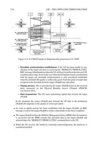
![RADIO RESOURCE MANAGEMENT 319
The above steps represent an overview of a best-case scenario when all the steps in the
procedure occur as desired. There are a number of possible failure cases which can necessitate
the initiation of recovery procedures; for example, the preferred target eNodeB may have no
spare resources to grant access to the UE, downlink synchronization might fail, or uplink
synchronization might fail because there is not sufficient uplink power. A detailed description
of all these possible scenarios can be found in the RRC protocol specification in [9].
13.6.3.1 Differences between LTE Intra- and Inter-Frequency Handover
Both intra-frequency and inter-frequency handovers between LTE cells are hard handovers.
Because of this, the steps involved for both handover types are very similar.
The handover interruption time is defined as the time between the end of the last TTI
in which the UE has received the handover command on the Physical Downlink Control
CHannel (PDCCH) and the time at which the UE is ready to start a PRACH transmission to
the new uplink. The interruption time can be broken down into the following contributions:
Tinterrupt = Tsearch + TIU + 20 ms
where Tsearch is the time required to find the target cell when the target cell is not already
known when the handover command is received by the UE. If the target cell is known,
then Tsearch = 0 ms. TIU is the interruption uncertainty to locate the first available PRACH
occasion in the new cell. 20 ms is added to allow for UE processing time required to execute
the handover.
13.6.4 Handover to UMTS
Handover to UMTS can be decomposed into two separate stages, each of which relates to an
identical stage in a single-mode handover procedure:
• Handover initiation. From a UE perspective this stage is no different to handover
initiation in the case of LTE intra- or inter-frequency handover.
• Radio link establishment to the target UMTS cell. This stage is identical to UMTS
inter-frequency handover. For this reason, handover execution delay requirements
in [1] are very similar to intra-UMTS hard handover requirements in [5].
As in the handover to LTE case, handover to UMTS may be blind or guided depending on
whether or not the UE has been able to synchronize to the target cell prior to receiving the
‘MOBILITY FROM E-UTRA’ RRC message.
13.6.5 Handover to GSM
Handover to GSM can also be decomposed into two separate stages, each of which relates to
an identical stage in a single-mode handover procedure:
• Handover initiation. From a UE perspective this stage is no different to the handover
initiation in the case of LTE intra- or inter-frequency handover.
• Radio link establishment to the target GSM cell. This stage is identical to a GSM
intra-system unsynchronized handover.](https://image.slidesharecdn.com/ltefromtheorytopractise-240124145854-b0067765/85/LTE_from_Theory_to_Practise-pdf-345-320.jpg)
![320 LTE – THE UMTS LONG TERM EVOLUTION
The handover to GSM interruption time can be decomposed into three main contributions:
Tinterrupt GSM = Tprocessing time + Tsync, blind + Tinterruption, guided
where Tprocessing time = 50 ms allows different implementations to reconfigure the modem for
GSM operation. Tsync, blind is the additional time allowance to enable a UE to synchronize
to the target GSM cell during a blind handover to GSM (100 ms). For a guided handover
this component does not apply (i.e. equals 0 ms). Tinterruption, guided = 40 ms is the worst-case
interruption time for a guided handover to GSM where the UE has been able to synchronize
to the target GSM cell before receiving the ‘MOBILITY FROM E-UTRA’ RRC message.
13.7 Concluding Remarks
The provision of seamless mobility is a key differentiator for cellular systems such as LTE, in
order to deliver an uninterrupted mobile user experience. The support for such functionality
in LTE not only covers LTE cells on the same frequency, but also extends to cells on different
frequencies and cells using a wide range of other radio access technologies. A wide range
of measurements and signalling are defined in LTE to support these different handover
scenarios. These aspects are carefully designed taking into account their potential impact on
other aspects of the user’s experience, such as UE power consumption and data interruption.
References6
[1] 3GPP Technical Specification 36.133, ‘Evolved Universal Terrestrial Radio Access (E-UTRA);
Requirements for Support of Radio Resource Management(Release 8)’, www.3gpp.org.
[2] 3GPP Technical Specification 25.213, ‘Technical Specification Group Radio Access Network;
Spreading and Modulation (FDD)’, www.3gpp.org.
[3] H. Holma and A. Toskala, WCDMA for UMTS, 2nd edition. John Wiley Sons, Ltd/Inc. 2002.
[4] M. Mouly and M.-B. Pautet, The GSM System for Mobile Communications. Cell Sys, 1992.
[5] 3GPP Technical Specification 25.133, ‘Technical Specification Group Radio Access Network;
Requirements for Support of Radio Resource Management (FDD)’, www.3gpp.org.
[6] 3GPP Technical Specification 36.214, ‘Evolved Universal Terrestrial Radio Access (E-UTRA);
Physical Layer – Measurements (Release 8)’, www.3gpp.org.
[7] 3GPP Technical Specification 25.302, ‘Technical Specification Group Radio Access Network;
Services Provided by the Physical Layer’, www.3gpp.org.
[8] 3GPP Technical Specification 36.213, ‘Evolved Universal Terrestrial Radio Access (E-UTRA);
Physical Layer Procedures (Release 8)’, www.3gpp.org.
[9] 3GPP Technical Specification 36.331, ‘Evolved Universal Terrestrial Radio Access (E-UTRA);
Radio Resource Control (RRC); Protocol Specification’, www.3gpp.org.
[10] Ericsson, ‘R1-073041: Reference Signal Received Quality, RSRQ, Measurement’,
www.3gpp.org, 3GPP TSG RAN WG1, meeting 49bis, Orlando, USA, June 2007.
[11] 3GPP Technical Specification 25.215, ‘Technical Specification Group Radio Access Network;
Physical Layer – Measurements (FDD)’, www.3gpp.org.
6All web sites confirmed 18th December 2008.](https://image.slidesharecdn.com/ltefromtheorytopractise-240124145854-b0067765/85/LTE_from_Theory_to_Practise-pdf-346-320.jpg)
![RADIO RESOURCE MANAGEMENT 321
[12] 3GPP Technical Specification 25.225, ‘Technical Specification Group Radio Access Network;
Physical Layer – Measurements (TDD)’, www.3gpp.org.
[13] 3GPP2 CS.0005-D, ‘Upper Layer (Layer 3) Signaling Standard for CDMA2000 Spread Spectrum
Systems Release D’, www.3gpp2.org.
[14] 3GPP2 CS.0024-A, ‘cdma2000 High Rate Packet Data Air Interface Specification’,
www.3gpp2.org.
[15] 3GPP Technical Specification 36.304, ‘Evolved Universal Terrestrial Radio Access (E-UTRA);
User Equipment (UE) Procedures in Idle Mode’, www.3gpp.org.
[16] 3GPP Technical Report 25.912, ‘Feasibility study for evolved Universal Terrestrial Radio Access
(UTRA) and Universal Terrestrial Radio Access Network (UTRAN)’, www.3gpp.org.](https://image.slidesharecdn.com/ltefromtheorytopractise-240124145854-b0067765/85/LTE_from_Theory_to_Practise-pdf-347-320.jpg)
![14
Broadcast Operation
Olivier Hus and Matthew Baker
14.1 Introduction
It was an early requirement of the Long-term Evolution (LTE) specifications [1] to support an
enhanced version of the Multimedia Broadcast/Multicast Service (MBMS) already available
in UTRAN1 and GERAN.2 MBMS aims to provide an efficient mode of delivery for both
broadcast and multicast services over the core network.
We first give a general overview of MBMS as a broadcast and multicast delivery system,
before reviewing in detail the enhancements to MBMS which can be supported by LTE
compared to UMTS Release 6. In particular, we describe how LTE is able in principle
to benefit from the new OFDM downlink radio interface to achieve radically improved
transmission efficiency and coverage by means of multicell ‘Single Frequency Network’
operation.
While most of these aspects are already well-developed in the first release of the LTE
specifications (Release 8), it was in fact necessary in the specification process in 3GPP to
prioritize some features over others, in order to expedite the commercial deployment of
LTE. The MBMS specifications for LTE are therefore not included in the first release of
LTE. Nevertheless the LTE physical layer has already been designed to support MBMS, and
essential components are implemented in Release 8 to ensure forward-compatibility for full
MBMS operation when the feature is finalized in later releases.
1UMTS Terrestrial Radio Access Network.
2GSM Edge Radio Access Network.
LTE – The UMTS Long Term Evolution: From Theory to Practice Stefania Sesia, Issam Toufik and Matthew Baker
© 2009 John Wiley Sons, Ltd. ISBN: 978-0-470-69716-0](https://image.slidesharecdn.com/ltefromtheorytopractise-240124145854-b0067765/85/LTE_from_Theory_to_Practise-pdf-348-320.jpg)

![BROADCAST OPERATION 325
The delivery of identical content to multiple users via unicast connections (point-to-point)
is usually a very inefficient method of transmission, both because of the waste of radio
resources (especially for high-bandwidth for multimedia applications) and because of the
signalling burden in the core network. Point-to-multipoint transmission modes lessen the
load on network resources by decreasing the total amount of data transmitted and reducing
signalling procedures significantly, particularly in the uplink.
At the physical layer, there is no difference between broadcast and multicast downlink
data transmissions. The difference between the two modes lies in the subscriber base:
broadcast services are available to all users without the need for subscriptions to particular
services, whereas availability of multicast services is restricted so that individual users need
to subscribe in order to be able to receive selected services. Multicasting can thus be seen as
‘broadcast via subscription’, with the possibility of charging for the subscription.
14.2.2 UMTS Release 6 MBMS Service and Delivery System
In UMTS, MBMS was first specified in Release 6 for the delivery of content in a point-
to-multipoint mode using the 3GPP core network and the UMTS Terrestrial Radio Access
Network (UTRAN).
Figure 14.2 shows the architectural model for the full Release 6 MBMS ‘content chain’ –
i.e. the path from the content provider to the MBMS receiver at the User Equipment (UE).
UE SGSN
UE GERAN
UTRAN
HLR
GGSN
TPF BM- SC
Uu Iu
Iu / Gb
Um
Gr
Gn / Gp Gi
PDN (e.g. Internet)
Gmb
Content
Provider/
Multicast
Broadcast
Source
Content
Provider/
Multicast
Broadcast
Source
Figure 14.2 UMTS Release 6 MBMS Network Architecture Model [2]. Reproduced by
permission of © 3GPP.
The full MBMS service and delivery system can be described as being made up of three
subsystems, outlined in the following sections.
14.2.2.1 Content Provision
Sources of MBMS content vary, but are normally assumed to be external to the core
network; one example of external content providers would be television broadcasters for](https://image.slidesharecdn.com/ltefromtheorytopractise-240124145854-b0067765/85/LTE_from_Theory_to_Practise-pdf-350-320.jpg)
![326 LTE – THE UMTS LONG TERM EVOLUTION
mobile television. The MBMS content is generally assumed to be IP based, and by design
the MBMS system is integrated with the IP Multimedia Subsystem (IMS) [3] service
infrastructure based on the Internet Engineering Task Force (IETF) Session Initiation
Protocol (SIP) [4].
The interface between the external content providers and the core network is the
Broadcast-Multicast Service Centre (BM-SC). The main functions provided by the BM-SC
are:
• Reception of MBMS content from external content providers;
• Providing application and media servers for the mobile network operator;
• Scheduling of MBMS services and transport of MBMS data into the core network;
• Management of user group membership, subscription and charging for sessions.
14.2.2.2 Core Network
In UMTS, the Gateway GPRS Support Node (GGSN) is the entry point into the core network
for MBMS multicast or broadcast traffic. This is connected to the Serving GPRS Support
Node (SGSN), which is the entry point into the Radio Access Network (RAN), either
UTRAN or GERAN, and supports mobility procedures. The SGSN also performs control
functions for each individual user: storage of user-specific information for each activated
MBMS service and generation of charging data for each user (for handling by the BM-SC).
14.2.2.3 Radio Access Network – UTRAN/GERAN and UE
The RAN, whether UTRAN or GERAN, is responsible for delivering MBMS data efficiently
to the designated MBMS service area. It performs the following functions:
• Choice of appropriate radio bearer based on the number of users within a cell;
• Transmission of MBMS service announcements;
• Initiation and termination of MBMS transmissions;
• Support of user mobility.
In UMTS Release 6 the transmission of MBMS is performed by single cells operating with
different scrambling codes, although signals from neighbouring cells can often be combined
to increase gain at reception. In Release 7, UMTS MBMS is enhanced to allow multiple
cells transmitting the same MBMS service to do so using the same scrambling code in a
synchronized manner; this allows joint equalization of the multicell transmissions in the UE’s
receiver in a manner which is to some extent analogous to the Single Frequency Network
method by which MBMS transmission occurs in LTE, as described in Section 14.3.
The final element in the MBMS content and service chain is the MBMS receiver itself:
the UE.](https://image.slidesharecdn.com/ltefromtheorytopractise-240124145854-b0067765/85/LTE_from_Theory_to_Practise-pdf-351-320.jpg)


![BROADCAST OPERATION 329
0.0 0.5 1.0 1.5 2.0 2.5 3.0
0.4
0.5
0.6
0.7
0.8
0.9
1.0
1 km cell radius
20 dB penetration loss
46 dBm eNB power
15 m antenna height
2 GHz
3 km/h
Coverage
(Probability
of
Packet
Error
Rate
1%)
Spectral Efficiency (bps/Hz)
Central cell surrounded by 3 rings of MBSFN cells
Central cell surrounded by 2 rings of MBSFN cells
Central cell surrounded by 1 ring of MBSFN cells
Central cell surrounded by interferers
Figure 14.4 Reduction in total downlink resource usage achievable using MBSFN
transmission [5]. Reproduced by permission of © 2007 Motorola.
Figure 14.5 MBSFN reference symbol pattern for 15 kHz subcarrier spacing. Reproduced
by permission of © 3GPP.
estimate, representing the composite channel from the set of cells transmitting the
MBSFN data.
In addition to these enhancements for MBSFN transmission, a second OFDM parameter-
ization is provided in LTE specifically for downlink-only multicast/broadcast transmissions.](https://image.slidesharecdn.com/ltefromtheorytopractise-240124145854-b0067765/85/LTE_from_Theory_to_Practise-pdf-354-320.jpg)
![330 LTE – THE UMTS LONG TERM EVOLUTION
This has an even longer CP, double the length of the extended CP, resulting in approximately
33 µs. This is designed to cater for deployments with very large differences in propagation
delay between the signals from different cells (typically up to 10 km). This is most likely to
occur for deployments at low carrier frequencies and large inter-site distances.
In order to avoid further increasing the overhead arising from the CP in this case, the
number of subcarriers per unit bandwidth is also doubled, giving a subcarrier spacing of
7.5 kHz. The cost of this is an increase in inter-carrier interference, especially in high-
mobility scenarios with a large Doppler spread. In choosing whether to use the 7.5 kHz
subcarrier spacing, there is therefore a trade-off between support for wide-area coverage
and support for high mobile velocities. It should be noted, however, that the maximum
Doppler shift is lower at the low carrier frequencies which are likely to be used in the typical
deployment scenario for the 7.5 kHz subcarrier spacing. The absolute frequency spacing
of the reference symbols for the 7.5 kHz is the same as for the 15 kHz subcarrier spacing
MBSFN pattern, resulting in a RS on every fourth subcarrier.
14.3.1.2 Time-synchronization in MBSFN Operation
We use the term MBSFN area to refer to the area within which cells transmit the same content
for MBSFN combining at the UEs.
The transmissions from the multiple cells (eNodeBs) in an MBSFN area must be tightly
time-synchronized with an accuracy of a few µs to achieve symbol-level alignment within
the CP. The method of achieving symbol-level synchronization is not defined in the LTE
specifications; this is left to the implementation of the eNodeB. Typical implementations are
likely to use satellite-based solutions (e.g. GPS) or possibly synchronized backhaul protocols
(e.g. [6]).
In addition, there is also a requirement for the content of the time-synchronized MBSFN
physical resource blocks to be aligned; this requires synchronization at the service provision
level, to avoid resource blocks containing different data causing interference at the receiver. A
synchronization mechanism for MBMS content is therefore also necessary: this is described
in Section 14.3.3.1.
Physical resources are allocated to a specific MCH by specifying a pattern of subframes:
the MCH Subframe Allocation Pattern (MSAP). One MCH contains data belonging to only
one MBSFN Area. MCHs from different MBSFN areas are time multiplexed onto different
subframes.
14.3.2 MBMS Deployment
The deployment of MBMS in LTE is supported in various configurations of geographical
cell distribution, carrier frequency allocation (known as ‘frequency layers’) and transmission
modes.
14.3.2.1 Areas Related to MBMS
A geographical area of the network where MBMS can be transmitted is called an MBMS
Service Area.
A geographical area where all eNodeBs can be synchronized and can perform MBSFN
transmissions is called an MBSFN Synchronization Area.](https://image.slidesharecdn.com/ltefromtheorytopractise-240124145854-b0067765/85/LTE_from_Theory_to_Practise-pdf-355-320.jpg)


![BROADCAST OPERATION 333
14.3.2.2 Dedicated and Mixed Carriers
LTE is designed to support MBMS either on a dedicated carrier in which all subframes are
used for MBSFN transmission or on a mixed MBSFN/unicast carrier which is shared between
MBMS and unicast services. In the latter case, the MBSFN and unicast services are time-
multiplexed using different subframes. Certain subframes are not allowed to be used for
MBSFN transmission: subframes 0, 4 and 5 in each 10 ms radio frame are reserved for
unicast transmission in order to avoid disrupting the synchronization signals, and to ensure
that sufficient common RS are available for decoding the broadcast system information.
A dedicated MBMS carrier is for downlink transmissions only, and cannot support uplink
connections (as there is no Physical Downlink Control Channel (PDCCH) to carry the control
signalling for the uplink).
14.3.2.3 Handover
Appropriate handover procedures need to be provided to maintain MBMS service continuity
as a UE moves across cell boundaries and MBMS Service Areas.
Four different scenarios exist for handover (i.e. cell reselection) in the context of MBMS
service continuity:
• Intra-frequency handover within an MBSFN area on a dedicated MBMS carrier: by
design, the service continuity is seamless as the terminal sees the whole service area
as a single cell;
• Inter-frequency handover between MBSFN operation on a dedicated MBMS carrier
and MBMS transmission on a mixed MBMS/unicast carrier: this is a difficult scenario
as the lack of an uplink channel for the dedicated MBMS carrier will prevent the usual
handover communication with UEs;
• Intra- or inter-frequency handover between MBSFN operation on a mixed MBMS/
unicast carrier and MBMS single-cell transmission on a mixed MBMS/unicast carrier:
handover would be possible through the unicast connection; however, this may be an
unrealistic solution when the number of receivers of MBSFN transmissions is high and
a mechanism would be needed to ensure that resources are not overloaded;
• Intra- or inter-frequency handover between MBMS single-cell transmissions on
a mixed MBMS/unicast carrier: this is a relatively simple scenario as handover
procedures would be very similar to normal unicast handover.
In summary, handover procedures to exit MBSFN mode on a dedicated layer are likely to
be tricky. Inter- or intra-frequency handover procedures from a mixed MBMS/unicast cell
would follow the traditional handover procedures.
14.3.2.4 Notification for Non-MBMS Services
A requirement for the design of LTE [1] was that it supports concurrent MBMS and non-
MBMS services for a smooth user experience: a user receiving one or several MBMS services
should be notified when a dedicated service (voice, data) is incoming and should be able to
take the call or get the data.](https://image.slidesharecdn.com/ltefromtheorytopractise-240124145854-b0067765/85/LTE_from_Theory_to_Practise-pdf-358-320.jpg)

![BROADCAST OPERATION 335
and, in contrast to non-MBMS traffic, hosts the PDCP3 layer of the user plane for header
compression for MBMS data packets for both multicell and single-cell transmission. The
MBMS GW then forwards the user-plane traffic to the eNodeBs.
Each eNodeB hosts the RLC and MAC layers of the protocol stack, including the
segmentation and reassembly functions. The other functions which remain to be hosted by
the eNodeB for MBMS mainly relate to single-cell MBMS operation.
The interfaces between the MBMS logical network entities are as follows:
• M1 interface (MBMS GW – eNodeB): A pure user plane interface; no control plane
application part is defined for this interface; IP multicast is used for point-to-multipoint
delivery of user packets for both single cell and multicell transmission. The SYNC
protocol [7] is used to ensure that content is synchronized for multicell MBSFN
transmission. This carries additional information which enables eNodeBs to identify
the radio frame timing and to detect packet loss.4 The stringent timing requirements of
the SYNC protocol would not apply to eNodeBs which only transmit MBMS in single-
cell mode. The integration of the SYNC protocol layer into the user-plane architecture
for MBMS content synchronization is shown in Figure 14.8.
RLC
MAC
PHY
UE
E-MBMS
Gateway
eNodeB
M1
RLC
MAC
PHY
eBM-SC
MBMS
packet
MBMS
packet
TNL TNL TNL
SYNC SYNC
SYNC Protocol to synchronize
data used to generate a certain
radio frame
Figure 14.8 User plane architecture including SYNC protocol for MBMS content
synchronization. Reproduced by permission of © 3GPP.
• M2 interface (MCE – eNodeB): A pure control-plane interface which conveys the
session control signalling to the eNodeB, adding the necessary radio configuration data
for multicell MBSFN transmission. This additional radio configuration data ensures
that the RLC/MAC entities located in the eNodeB are configured appropriately and
consistently in order to deliver synchronized content. The SCTP protocol [8] is used
over the M3 interface to carry the application part.
3Packet Data Convergence Protocol – see Section 4.2.
4The details of the SYNC protocol remain to be defined in a later release of LTE, but it is expected to be based
on timestamps.](https://image.slidesharecdn.com/ltefromtheorytopractise-240124145854-b0067765/85/LTE_from_Theory_to_Practise-pdf-360-320.jpg)

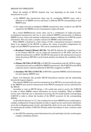

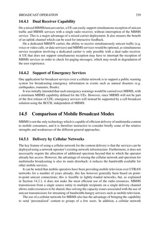
![340 LTE – THE UMTS LONG TERM EVOLUTION
offers the possibility of a built-in return channel, which is a key feature for the provision
of interactive services.
14.5.2 Delivery by Broadcast Networks
Mobile broadcast services may alternatively be provided by standalone broadcast systems
such as Digital Video Broadcasting-Terrestrial (DVB-T) and Digital Audio Broadcasting
(DAB). Originally developed for fixed receivers, specific mobile versions of these standards
have been developed, namely Digital Video Broadcasting-Handheld (DVB-H) and Digital
Mobile Broadcasting (DMB) respectively. Other proprietary broadcast solutions have also
been developed, such as MediaFLO (Forward Link Only).
These systems typically assume the use of a relatively small number of higher-powered
transmitters designed to cover a wide geographical area. For broadcast service provision, user
capacity constraints do not require the use of small cells.
Such systems can therefore achieve relatively high data rates with excellent wide-area
coverage. However, they clearly also require dedicated spectrum in which to operate, the
construction and operation of a network of transmitters additional to that provided for the
cellular network, and the presence of additional hardware in the mobile terminals.
Standalone broadcast systems are also by definition ‘downlink-only’: they do not provide
a direct return channel for interactive services, although it may be possible to use the cellular
network for this purpose.
14.5.3 Services and Applications
Both cellular delivery (MBMS) and standalone broadcast methods enable the delivery of a
variety of multimedia services and applications, the most fashionable being mobile television.
This gives network operators the opportunity to differentiate their service offerings.
In some ways, cellular delivery (MBMS) and standalone broadcast (e.g. DVB-H) systems
can be seen as complementary. The mobile television industry and market are changing
rapidly, and may be better described as part of the mobile entertainment industry, where new
market rules prevail. An example of this is the concept of the ‘long tail of content’ [9] which
describes the consumption of products or services across a large population, as illustrated in
Figure 14.10: given a large availability of choice, a few very popular products or services
will dominate the market for the majority of consumers; a large number of other products or
services will only find a niche market.
This is a very appropriate representation of the usage of broadcast television, whether
fixed or mobile: viewing figures for a few main channels (typically national broadcasters)
are high, while usage is low for a profusion of specialist channels that gather a limited yet
dedicated audience.
One obvious possibility then is to map this simple model to the earlier description of
broadcast or multicast transmissions:
• Broadcast: for transmitting a few main channels to all users, e.g. via DVB-H or MBMS;
• Multicast: for transmitting numerous specialist channels on-demand to select groups
of users, e.g. via MBMS.](https://image.slidesharecdn.com/ltefromtheorytopractise-240124145854-b0067765/85/LTE_from_Theory_to_Practise-pdf-365-320.jpg)
![BROADCAST OPERATION 341
Many service choices, low usage patterns
Few service choices,
high usage patterns
Number of channels
Number of viewers
Figure 14.10 The ‘Long Tail of Content’.
The deployment of mobile broadcast technology worldwide (whether by cellular MBMS
or standalone broadcast) is very much dependent on the availability of spectrum and on the
offer of services in each country, while infrastructure costs and content agreements between
network operators and broadcasters are also significant factors.
Taking again the example of mobile television, what matters ultimately to the user is the
quality of reception on their terminal, and mobility. Deployment of MBMS in LTE networks
will bring an increase in capacity compared to what is achievable in a UMTS network,
notably by exploiting the use of Single Frequency Network operation based on OFDM –
which incidentally is the transmission method also used by DVB-H, DMB and MediaFLO.
References6
[1] 3GPP Technical Report 25.913, ‘Requirements for Evolved UTRA (E-UTRA) and Evolved
UTRAN (E-UTRAN) (Release 7)’, www.3gpp.org.
[2] 3GPP Technical Specification 23.246, ‘Multimedia Broadcast/Multicast Service (MBMS);
Architecture and Functional Description (Release 6)’, www.3gpp.org.
[3] 3GPP Technical Specification 23.228, ‘IP Multimedia Subsystem (IMS); Stage 2 (Release 8)’,
www.3gpp.org.
[4] Internet Engineering Task Force, ‘RFC3261 Session Initiation Protocol’, www.ietf.org.
[5] Motorola, ‘R1-070051: Performance of MBMS Transmission Configurations’, www.3gpp.org,
3GPP TSG RAN WG1, meeting 47bis, Sorrento, Italy, January 2007.
[6] IEEE1588, ‘IEEE 1588 Standard for a Precision Clock Synchronization Protocol for Networked
Measurement and Control Systems’, http://ieee1588.nist.gov.
6All web sites confirmed 18th December 2008.](https://image.slidesharecdn.com/ltefromtheorytopractise-240124145854-b0067765/85/LTE_from_Theory_to_Practise-pdf-366-320.jpg)
![342 LTE – THE UMTS LONG TERM EVOLUTION
[7] 3GPP Technical Specification 36.300, ‘Evolved Universal Terrestrial Radio Access (E-UTRA)
and Evolved Universal Terrestrial Radio Access (E-UTRAN); Overall description; Stage 2’,
www.3gpp.org.
[8] Internet Engineering Task Force, ‘RFC4960 Stream Control Transmission Protocol’, www.ietf.org.
[9] D. Anderson, The Long Tail: Why the Future of Business is Selling Less of More. New York, USA:
Hyperion, 2006.](https://image.slidesharecdn.com/ltefromtheorytopractise-240124145854-b0067765/85/LTE_from_Theory_to_Practise-pdf-367-320.jpg)


![346 LTE – THE UMTS LONG TERM EVOLUTION
in frequency-selective channels. SC-FDMA avoids the high level of intra-cell interference
associated with DS-CDMA which significantly reduces system capacity and limits the use of
adaptive modulation. A code-multiplexed uplink also suffers the drawback of an increased
CM/PAPR if multi-code transmission is used from a single UE.
The use of OFDMA (Orthogonal Frequency Division Multiple Access) for the LTE uplink
would have been attractive due to the possibility for full uplink-downlink commonality.
In principle, an OFDMA scheme similar to the LTE downlink could satisfy all the uplink
design criteria listed above, except for low CM/PAPR. As discussed in Section 5.2.2.1, much
research has been conducted in recent years on methods to reduce the CM/PAPR of OFDM;
however, in general the effectiveness of these methods requires careful practical evaluation
against their associated complexity and/or overhead (for example, in terms of additional
signalling or additional transmission bandwidth used to achieve the CM/PAPR reduction).
SC-FDMA combines the desirable characteristics of OFDM outlined in Section 5.2 with
the low CM/PAPR of single-carrier transmission schemes.
Like OFDM, SC-FDMA divides the transmission bandwidth into multiple parallel
subcarriers, with the orthogonality between the subcarriers being maintained in frequency-
selective channels by the use of a Cyclic Prefix (CP) or guard period. The use of a CP prevents
Inter-Symbol Interference (ISI) between SC-FDMA information blocks. It transforms the
linear convolution of the multipath channel into a circular convolution, enabling the receiver
to equalize the channel simply by scaling each subcarrier by a complex gain factor as
explained in Chapter 5.
However, unlike OFDM, where the data symbols directly modulate each subcarrier
independently (such that the amplitude of each subcarrier at a given time instant is set by the
constellation points of the digital modulation scheme), in SC-FDMA the signal modulated
onto a given subcarrier is a linear combination of all the data symbols transmitted at the same
time instant. Thus in each symbol period, all the transmitted subcarriers of an SC-FDMA
signal carry a component of each modulated data symbol. This gives SC-FDMA its crucial
single-carrier property, which results in the CM/PAPR being significantly lower than pure
multicarrier transmission schemes such as OFDM.
15.2 SC-FDMA Principles
15.2.1 SC-FDMA Transmission Structure
An SC-FDMA signal can, in theory, be generated in either the time-domain or the frequency-
domain [1]. Although the two techniques are duals and ‘functionally’ equivalent, in practice,
the time-domain generation is less bandwidth-efficient due to time-domain filtering and
associated requirements for filter ramp-up and ramp-down times [2, 3]. Nevertheless, we
describe both approaches here to facilitate understanding of the principles of SC-FDMA in
both domains.
15.2.2 Time-Domain Signal Generation
Time-domain generation of an SC-FDMA signal is shown in Figure 15.1. It can be seen to
be similar to conventional single-carrier transmission.
The input bit stream is mapped into a single-carrier stream of QPSK or QAM symbols,
which are grouped into symbol-blocks of length M. This may be followed by an optional](https://image.slidesharecdn.com/ltefromtheorytopractise-240124145854-b0067765/85/LTE_from_Theory_to_Practise-pdf-370-320.jpg)
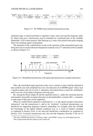
![348 LTE – THE UMTS LONG TERM EVOLUTION
consecutive subcarriers is hopped in the frequency domain, especially if the time interval
between hops is shorter than the duration of a block of channel-coded data.
Different users’ transmissions, using different repetition factors or bandwidths, remain
orthogonal on the uplink when the following conditions are met:
• The users occupy different sets of subcarriers. This may in general be accomplished
either by introducing a user-specific frequency shift (typically for the case of localized
transmissions) or alternatively by arranging for different users to occupy interleaved
sets of subcarriers (typically for the case of distributed transmissions). The latter
method is known in the literature as Interleaved Frequency Division Multiple Access
(IFDMA) [4].
• The received signals are properly synchronized in time and frequency.
• The CP is longer than the sum of the delay spread of the channel and any residual
timing synchronization error between the users.
The SC-FDMA time-domain generated signal has a similar level of CM/PAPR as pulse-
shaped single-carrier modulation. ISI in multipath channels is prevented by the CP, which
enables efficient equalization at the receiver by means of a Frequency Domain Equalizer
(FDE) [5,6].
15.2.3 Frequency-Domain Signal Generation (DFT-S-OFDM)
Generation of an SC-FDMA signal in the frequency domain uses a Discrete Fourier
Transform-Spread OFDM (DFT-S-OFDM) structure [7–9] as shown in Figure 15.3.
The first step of DFT-S-OFDM SC-FDMA signal generation is to perform an M-point
DFT operation on each block of M QAM data symbols. Zeros are then inserted among the
outputs of the DFT in order to match the DFT size to an N-subcarrier OFDM modulator
(typically an Inverse Fast Fourier Transform (IFFT)). The zero-padded DFT output is mapped
to the N subcarriers, with the positions of the zeros determining to which subcarriers the
DFT-precoded data is mapped.
Usually N is larger than the maximum number of occupied subcarriers, thus providing
for efficient oversampling and ‘sinc’ (sin(x)/x) pulse-shaping. The equivalence of DFT-
S-OFDM and a time-domain-generated SC-FDMA transmission can readily be seen by
considering the case of M = N, where the DFT operation cancels the IFFT of the OFDM
modulator resulting in the data symbols being transmitted serially in the time domain.
However, this simplistic construction would not provide any oversampling or pulse-shape
filtering.
As with the time-domain approach, DFT-S-OFDM is capable of generating both localized
and distributed transmissions:
• Localized transmission. The subcarrier mapping allocates a group of M adjacent
subcarriers to a user. M N results in zero being appended to the output of the DFT
spreader resulting in an upsampled/interpolated version of the original M QAM data
symbols at the IFFT output of the OFDM modulator. The transmitted signal is thus
similar to a narrowband single carrier with a CP (equivalent to time-domain generation
with repetition factor L = 1) and ‘sinc’ pulse-shaping filtering (circular filtering).](https://image.slidesharecdn.com/ltefromtheorytopractise-240124145854-b0067765/85/LTE_from_Theory_to_Practise-pdf-372-320.jpg)
![UPLINK PHYSICAL LAYER DESIGN 349
f0
f1
fM- 1
f0
f1
fM- 1
Subcarrier
Mapping
N-point
IFFT
Add cyclic
prefix
Parallel to
Serial
converter
M-point
DFT
Spreading
f0
f1
fM- 1
f0
f1
fM- 2
Localized
Subcarrier
Mapping
0
0
0
0
0
0
0
0
0
0
f2
f3
fM- 4
f
fM-1
f
fM- 3
f
Localized
0 1 2 3 4
Frequency Frequency
f0
f1
fM-
f0
f1
fM-
Distributed
Subcarrier
Mapping
f2
f
f3
f
fM-
f
fM-
f
fM-
f
0
0
0
0
0
0
0
0
0
0
0
0
0
0
0
0
Distributed
1
2
3
4
Serial to
Parallel
Converter
Incoming Bit
Stream
m bits
Bit to
Constellation
Mapping
Bit to
Constellation
Mapping
Bit to
Constellation
Mapping
m bits
m bits
x(0,n)
x(1,n)
x(M - 1,n)
Serial to
Parallel
Converter
Bit to
Constellation
Mapping
Bit to
Constellation
Mapping
-
Transmission
circuitry
Figure 15.3 SC-FDMA frequency-domain transmit processing (DFT-S-OFDM) showing
localized and distributed subcarrier mappings.
• Distributed transmission. The subcarrier mapping allocates M equally-spaced sub-
carriers (e.g. every Lth subcarrier). (L − 1) zeros are inserted between the M DFT
outputs, and additional zeros are appended to either side of the DFT output prior to the
IFFT (ML N). As with the localized case, the zeros appended on either side of the
DFT output provide upsampling or sinc interpolation, while the zeros inserted between
the DFT outputs produce waveform repetition in the time domain. This results in a
transmitted signal similar to time-domain IFDMA with repetition factor L and ‘sinc’
pulse-shaping filtering.
As for the time-domain SC-FDMA signal generation (in Section 15.2.2), orthogonality
between different users with different data rate requirements can be achieved by assigning
each user a unique set of subcarriers. The CP structure is the same as for the time-domain
signal generation, and therefore the same efficient FDE techniques can be employed at the
receiver [5,6].
It is worth noting that, in principle, any unitary matrix can be used in the place of the DFT
for the spreading operation with similar performance [10]. However, the use of non-DFT
spreading would result in increased CM/PAPR since the transmitted signal would no longer
have the single carrier characteristic.
15.3 SC-FDMA Design in LTE
Having outlined the key principles of SC-FDMA transmission, we now explain the applica-
tion of SC-FDMA to the LTE uplink.](https://image.slidesharecdn.com/ltefromtheorytopractise-240124145854-b0067765/85/LTE_from_Theory_to_Practise-pdf-373-320.jpg)
![350 LTE – THE UMTS LONG TERM EVOLUTION
Cubic metric
0
0.5
1
1.5
2
2.5
3
3.5
4
4.5
QPSK 16QAM 64QAM
Cubic
metric
(dB)
IFDMA
DFT-S-OFDM
OFDM
Figure 15.4 Cubic metric comparison of time-domain SC-FDMA generation (IFDMA),
frequency-domain SC-FDMA generation (DFT-S-OFDM) and OFDM.
15.3.1 Transmit Processing for LTE
Although the frequency-domain generation of SC-FDMA (DFT-S-OFDM) is functionally
equivalent to the time-domain SC-FDMA signal generation, each technique requires a
slightly different parameterization for efficient signal generation [3]. The pulse-shaping filter
used in the time domain SC-FDMA generation approach in practice has a non-zero excess
bandwidth, resulting in bandwidth efficiency which is smaller than that achievable with the
frequency domain method with its inherent ‘sinc’ (zero excess bandwidth) pulse-shaping
filter which arises from the zero padding and IFFT operation.
For example, for a 5 MHz operating bandwidth, physical layer parameters optimized for
time-domain implementation might have a sampling rate of 4.096 Mps (256 subcarriers with
16 kHz subcarrier spacing) resulting in bandwidth efficiency of 82% [2]. An equivalent
set of parameters optimized for the frequency-domain generation can support a bandwidth
efficiency of 90% (with 300 occupied subcarriers and 15 kHz subcarrier spacing). Thus,
with frequency-domain processing, a 10% increase in bandwidth efficiency can be achieved,
allowing higher data rates.
The non-zero excess bandwidth pulse-shaping filter in the time-domain generation also
requires ramp-up and ramp-down times of 3–4 samples duration, while for DFT-S-OFDM
there is no explicit pulse-shaping filter, resulting in a much shorter ramp time similar
to OFDM. However, the pulse-shaping filter in the time-domain generation does provide
the benefit of reduced CM by approximately 0.25–0.5 dB compared to DFT-S-OFDM, as
shown in Figure 15.4. Thus there is a trade-off between bandwidth efficiency and CM/PAPR
reduction between the time- and frequency-domain SC-FDMA generation methods.
Frequency-domain signal generation for the LTE uplink has a further benefit in that it
allows a very similar parameterization to be adopted as for the OFDM downlink, including
the same subcarrier spacing, number of occupied subcarriers in a given bandwidth, and CP
lengths. This provides maximal commonality between uplink and downlink, including for
example the same clock frequency.
For these reasons, the SC-FDMA parameters chosen for the LTE uplink have been
optimized under the assumption of frequency-domain DFT-S-OFDM signal generation.](https://image.slidesharecdn.com/ltefromtheorytopractise-240124145854-b0067765/85/LTE_from_Theory_to_Practise-pdf-374-320.jpg)

![352 LTE – THE UMTS LONG TERM EVOLUTION
Table 15.2 LTE Uplink SC-FDMA parametrization for selected carrier bandwidths.
Carrier bandwidth (MHz)
1.4 3 5 10 15 20
FFT size 128 256 512 1024 1536 2048
Sampling rate: M/N × 3.84 MHz 1/2 1/1 2/1 4/1 6/1 8/1
Number of subcarriers 72 180 300 600 900 1200
Number of RBs 6 15 25 50 75 100
Bandwidth efficiency (%) 77.1 90 90 90 90 90
transmitted repeatedly in multiple consecutive subframes, with only one set of signalling
messages for the whole transmission. The LTE uplink allows groups of 4 TTIs to be ‘bundled’
in this way, in addition to the normal 1 ms TTI.
In practice in LTE, all the uplink data transmissions are localized, using contiguous
blocks of subcarriers. This simplifies the transmission scheme, and enables the same RB
structure to be used as in the downlink. Frequency-diversity can still be exploited by means
of frequency hopping, which can occur both within one subframe (at the boundary between
the two slots) and between subframes. In the case of frequency hopping within a subframe,
the channel coding spans the two transmission frequencies, and therefore the frequency-
diversity gain is maximized through the channel decoding process. The only instance of
distributed transmission in the LTE uplink (using an IFDMA-like structure) is for the
‘Sounding Reference Signals’ (SRSs) which are transmitted to enable the eNodeB to perform
uplink frequency-selective scheduling; these are discussed in Section 16.6.
Like the downlink, the LTE uplink supports scalable system bandwidths from approxi-
mately 1.4 MHz up to 20 MHz with the same subcarrier spacing and symbol duration for
all bandwidths. The uplink scaling for the bandwidths supported in the first release of LTE
is shown in Table 15.2. Note that the sampling rates resulting from the indicated FFT sizes
are designed to be small rational multiples of the UMTS 3.84 MHz chip rate, for ease of
implementation in a multimode UE.
Note that in the OFDM downlink parameter specification, the d.c. subcarrier is unused
in order to support direct conversion (zero IF3) architectures. In contrast, no unused d.c.
subcarrier is possible for SC-FDMA (as shown in Table 15.2) as it can affect the low
CM/PAPR property of the transmit signal. These issues are discussed in Chapter 22.
15.3.3 d.c. Subcarrier in SC-FDMA
Direct conversion transmitters and receivers can introduce distortion at the carrier frequency
(zero frequency or d.c. in baseband), for example arising from local oscillator leakage.
In this section we explore three possible configurations of the d.c. subcarrier which were
considered in the design of the LTE uplink in order to minimize d.c. distortion effects on the
packet error rate and the CM/PAPR [11].
• Option 1. The d.c. subcarrier distortion region falls in the middle of a RB, such that
one of the RBs includes information modulated at d.c. (e.g. 600 subcarriers for 10 MHz
3Intermediate Frequency.](https://image.slidesharecdn.com/ltefromtheorytopractise-240124145854-b0067765/85/LTE_from_Theory_to_Practise-pdf-376-320.jpg)

![354 LTE – THE UMTS LONG TERM EVOLUTION
…………………….
f0
f1
fM- 1
f0
f1
fM- 1
Symbol to
Subcarrier
Mapping
N-point
IFFT
Add cyclic
prefix
Parallel to
Serial
converter
M-point
FFT
Serial to
Parallel
Converter
Incoming Bit
Stream
m bits
Bit to
Constellation
Mapping
Bit to
Constellation
Mapping
Bit to
Constellation
Mapping
m bits
m bits
x(0,n)
x(1,n)
x(M - 1,n)
Serial to
Parallel
Converter
Bit to
Constellation
Mapping
Bit to
Constellation
Mapping
Bit to
Constellation
Mapping
-
Transmission
circuitry
Frequency
Domain
Spectra
Shaping
fL- 1
f
…………………….
Figure 15.6 SC-FDMA (DFT-S-OFDM) with Pulse Shaping by Frequency Domain Spectral
Shaping (FDSS).
filter can further reduce the CM/PAPR, but at the expense of spectral efficiency (due to the
resulting non-zero excess filter bandwidth similar to that of the time domain SC-FDMA
signal generation described in Section 15.2.2). As a result of this trade-off, additional pulse-
shaping is not specified in LTE, but we review here some theoretical pulse-shaping techniques
in order to elucidate the reasoning behind this decision.
Frequency-domain SC-FDMA transmit processing allows any pulse shaping to be imple-
mented efficiently in the frequency-domain, after the DFT and prior to subcarrier mapping,
by element-wise multiplication with the spectrum of the desired pulse-shaping filter. This is
called Frequency Domain Spectral Shaping (FDSS) and is shown in Figure 15.6.
The use of pulse-shaping filters or FDSS window functions, such as Root Raised Cosine
(RRC) [12] or Kaiser window [13], was considered for LTE in order to reduce CM/PAPR,
especially for lower order modulations such as QPSK to enhance uplink coverage. The
bandwidth expansion caused by FDSS requires the code rate to be increased for a given
data rate. In order for FDSS to provide a net performance benefit (lower SINR requirement
than without pulse shaping, for the same data rate), power boosting is required, with the size
of the boost being approximately equal to the CM reduction achieved by FDSS.
We first consider the Kaiser window, which is defined as
w(n) =
K1
I0(γ )
I0(β)
0 ≤ n ≤ M
0 otherwise
(15.1)
where γ = β
!
1 − ((n − p)/p)2, p = M/2, I0(·) is the modified Bessel function of the first
kind and K1 is the scaling factor needed to obtain the same power as a rectangular window
of length (M + 1) with unit amplitude. The parameter β is a shape factor which controls the
smoothness of the window in a similar way to the roll-off factor α of a RRC filter.
The CM benefit obtained from the Kaiser window with different values of the shape
factor β for QPSK modulation is shown in Figure 15.7 [14]. As can be seen, the benefit](https://image.slidesharecdn.com/ltefromtheorytopractise-240124145854-b0067765/85/LTE_from_Theory_to_Practise-pdf-378-320.jpg)

![356 LTE – THE UMTS LONG TERM EVOLUTION
y = 2.6172x
2
+ 0.032x
R
2
= 1
0.00
0.20
0.40
0.60
0.80
1.00
1.20
1.40
1.60
0.00 0.10 0.20 0.30 0.40 0.50 0.60 0.70
Optimal RRC roll-off factor, D
SINR
gain,
Spectral
Efficiency
SINR gain Spec. Efficiency SINR gain
Little SINR benefit in spectral efficiency (K)
region for ER=1/3 Turbo Coder
(no benefit if no power boosting used)
Largest SINR benefit in very low and
unused spectral efficiency (K) region
ER=1/3, Mod=2
Figure 15.9 SINR gain and spectral efficiency η versus optimal RRC filter roll-off factor α
for QPSK.
-0.80
-0.60
-0.40
-0.20
0.00
0.20
0.40
0.60
0.80
1.00
1.20
0.00 0.25 0.50 0.75 1.00 1.25 1.50 1.75 2.00
Spectral Efficiency, K
SINR
Gain
from
Windowing
(dB)
SINR gain
SINR gain with CM boost
3RB
No Power De-rating - 24dBm QPSK
ER=1/3, QPSK
Loss - no boosting possible
Gain - boosting possible
10 RB
1RB
2RB
4RB
6RB
Operating Region: 7.95kbps AMR
25RB
Figure 15.10 Maximum SINR gain from FDSS using optimal RRC filter roll-off factor (α)
for QPSK.
benefit is in the very low spectral efficiency (η) region which is generally unused. Little SINR
benefit is observed in the η region for code rates 1/3. Without power boosting, there is no
performance benefit or performance loss for RRC spectral shaping. Moreover, FDSS cannot
be applied to reference symbols,in order to prevent degradation of the channel estimation.
As discussed in Chapter 22, CM is not a problem for UEs operating at a maximum power
level for resource allocations of up to 10 RBs. This means that there is no benefit possible
from FDSS given that UEs at the cell edge would often have less than 10 RBs allocated. With
no power boosting, FDSS results in a throughput loss since the resulting spectral efficiency
loss cannot be compensated as shown in Figure 15.10 [15].
Therefore, in LTE no pulse-shaping is used – in other words, the FDSS window is
rectangular.](https://image.slidesharecdn.com/ltefromtheorytopractise-240124145854-b0067765/85/LTE_from_Theory_to_Practise-pdf-380-320.jpg)
![UPLINK PHYSICAL LAYER DESIGN 357
15.4 Summary
The important properties of the SC-FDMA transmission scheme used for the LTE uplink
are derived from its multicarrier OFDM-like structure with single-carrier characteristic. The
multicarrier-based structure gives the LTE uplink the same robustness against ISI as the LTE
downlink, with low-complexity frequency-domain equalization being facilitated by the CP.
At the same time, the DFT-based precoding ensures that the LTE uplink possesses the low CM
required for efficient UE design. Crucially, the LTE uplink is designed to be orthogonal in the
frequency domain between different UEs, thus virtually eliminating the intra-cell interference
associated with CDMA.
The parameters of the LTE uplink are designed to ensure maximum commonality with the
downlink, and to facilitate frequency-domain DFT-S-OFDM signal generation.
The localized resource allocation scheme of the LTE uplink allows both frequency-
selective scheduling and the exploitation of frequency diversity, the latter being achieved
by means of frequency hopping.
The following chapters explain the application of SC-FDMA in LTE in more detail,
showing how reference signals for channel estimation, data transmissions and control
signalling are multiplexed together.
References4
[1] Motorola, ‘R1-050397: EUTRA Uplink Numerology and Frame Structure’, www.3gpp.org, 3GPP
TSG RAN WG1, meeting 41, Athens, Greece, May 2005.
[2] Motorola, ‘R1-050584: EUTRA Uplink Numerology and Design’, www.3gpp.org, 3GPP TSG
RAN WG1, meeting 41bis, Sophia Antipolis, France, June 2005.
[3] Motorola, ‘R1-050971: Single Carrier Uplink Options for E-UTRA’, www.3gpp.org, 3GPP TSG
RAN WG1, meeting 42, London, UK, August 2005.
[4] U. Sorger, I. De Broeck and M. Schnell,‘Interleaved FDMA – A New Spread-Spectrum Multiple-
Access Scheme’, in Proc. IEEE International Conference on Communications, pp. 1013–1017,
1998.
[5] H. Sari, G. Karam and I. Jeanclaude, ‘Frequency-Domain Equalization of Mobile Radio
and Terrestrial Broadcast Channels’, in Proc. IEEE Global Telecommunications Conference,
November 1994.
[6] D. Falconer, S. L. Ariyavisitakul, A. Benyamin-Seeyar and B. Eidson, ‘Frequency Domain
Equalization for Single-carrier Broadband Wireless Systems’. IEEE Communications Magazine,
Vol. 40, pp. 58–66, April 2002.
[7] K. Bruninghaus and H. Rohling, ‘Multi-carrier Spread Spectrum and its Relationship to Single-
carrier Transmission’, in Proc. IEEE Vehicular Technology Conference, May 1998.
[8] D. Galda and H. Rohling, ‘A Low Complexity Transmitter Structure for OFDM-FDMA Uplink
Systems’, in Proc. IEEE Vehicular Technology Conference, May 2002.
[9] R. Dinis, D. Falconer, C. T. Lam and M. Sabbaghian, ‘A Multiple Access Scheme for the Uplink of
Broadband Wireless Systems’, in Proc. IEEE Global Telecommunications Conference, November
2004.
4All web sites confirmed 18th December 2008.](https://image.slidesharecdn.com/ltefromtheorytopractise-240124145854-b0067765/85/LTE_from_Theory_to_Practise-pdf-381-320.jpg)
![358 LTE – THE UMTS LONG TERM EVOLUTION
[10] V. Nangia and K. L. Baum, ‘Experimental Broadband OFDM System – Field Results for OFDM
and OFDM with Frequency Domain Spreading’, in Proc. IEEE International Conference on
Vehicular Technology, Vancouver, BC, Canada, September 2002.
[11] Motorola, ‘R1-062061: Uplink DC Subcarrier Distortion Considerations in LTE’, www.3gpp.org,
3GPP TSG RAN WG1, meeting 46, Tallinn, Estonia, August 2006.
[12] NTT DoCoMo, NEC, and SHARP, ‘R1-050702: DFT-spread OFDM with Pulse Shaping Filter in
Frequency Domain in Evolved UTRA Uplink’, www.3gpp.org, 3GPP TSG RAN WG1, meeting
42, London, UK, August 2005.
[13] Huawei, ‘R1-051434: Optimum family of spectrum-shaping functions for PAPR reduction in SC-
FDMA’, www.3gpp.org, 3GPP TSG RAN WG1, meeting 43, Seoul, Korea, November 2005.
[14] Motorola, ‘R1-070564: Frequency Domain Spectral Shaping for LTE’, www.3gpp.org, 3GPP
TSG RAN WG1, meeting 47bis, Sorrento, Italy, January 2007.
[15] Motorola, ‘R1-070047: UE Power De-rating Reduction Techniques in LTE’, www.3gpp.org,
3GPP TSG RAN WG1, meeting 47bis, Sorrento, Italy, January 2007.](https://image.slidesharecdn.com/ltefromtheorytopractise-240124145854-b0067765/85/LTE_from_Theory_to_Practise-pdf-382-320.jpg)

![360 LTE – THE UMTS LONG TERM EVOLUTION
are also orthogonal to each other. The SRSs, if configured by higher layer signalling, are
transmitted on the last SC-FDMA symbol in a subframe; SRS can occupy a bandwidth
different from that used for data transmission. UEs transmitting SRS in the same subframe
can be multiplexed via either Frequency or Code Division Multiplexing (FDM or CDM
respectively), as explained in Section 16.6.
Desirable characteristics for the uplink RSs include:
• Constant amplitude in the frequency domain for equal excitation of all the allocated
subcarriers for unbiased channel estimates.
• Low Cubic Metric (CM) in the time domain (at worst no higher than that of the data
transmissions, while a lower CM for RSs than the data can be beneficial in enabling
the transmission power of the RSs to be boosted at the cell-edge).
• Good autocorrelation properties for accurate channel estimation.
• Good cross-correlation properties between different RSs to reduce interference from
RSs transmitted on the same resources in other (or, in some cases, the same) cells.
The following sections explain how these characteristics are achieved in LTE.
16.2 RS Signal Sequence Generation
The uplink reference signals in LTE are mostly based on Zadoff–Chu (ZC) sequences2 [1,2].
The fundamental structure and properties of these sequences are described in Section 7.2.1.
These sequences satisfy the desirable properties for RS mentioned above, exhibiting
0 dB CM, ideal cyclic autocorrelation, and optimal cross-correlation. The cross-correlation
property results in the impact of an interfering signal being spread evenly in the time domain
after time-domain correlation of the received signal with the desired sequence; this results in
more reliable detection of the significant channel taps. However, in practice the CM of a ZC
sequence is degraded from the theoretical 0 dB value at the Nyquist sampling rate. This arises
from the presence of unused guard subcarriers at each end of the sequence (due to the number
of occupied RS subcarriers being less than the IFFT (Inverse Foot Fourier Transform) size of
the OFDM (Orthogonal Frequency Division Multiplexing) modulator), and results in the ZC
sequence effectively being oversampled in the time domain.
The RS sequence length, Np, is equal to the number of assigned subcarriers, which is a
multiple of the number of subcarriers per RB, NRB
sc = 12, i.e.
Np = MRS
sc = m · NRB
sc , 1 ≤ m ≤ NUL
RB (16.1)
where NUL
RB is the uplink system bandwidth in terms of RBs.
The length-Np RS sequence is directly applied (without Discrete Fourier Transform
(DFT) spreading) to Np reference signal subcarriers at the input of the IFFT as shown in
Figure 16.1 [3]. Recall that a ZC sequence of odd-length NZC is given by
aq(n) = exp −j2πq
n(n + 1)/2 + ln
NZC
(16.2)
2Note that ZC sequences are a special case of the Generalized Chirp-Like (GCL) sequences.](https://image.slidesharecdn.com/ltefromtheorytopractise-240124145854-b0067765/85/LTE_from_Theory_to_Practise-pdf-384-320.jpg)
![UPLINK REFERENCE SIGNALS 361
Figure 16.1 Transmitter structure for SC-FDMA reference signals. Note that no DFT
spreading is applied to the RS sequence.
where q = 1, . . . , NZC − 1 is the ZC sequence index (also known as the root index), n =
0, 1, . . . , NZC − 1, and l = 0 in LTE.
In LTE, NZC is selected to be the largest prime number smaller than or equal to Np. The
ZC sequence of length NZC is then cyclically extended to the target length Np as follows:
r̄q(n) = aq(n mod NZC), n = 0, 1, . . . , Np − 1 (16.3)
The cyclic extension in the frequency domain preserves the constant amplitude properties
(in the frequency domain) and also the zero autocorrelation cyclic shift orthogonality. Cyclic
extension of the ZC sequences is used rather than truncation, as in general it provides better
CM characteristics. For sequence lengths of three or more RBs, this provides at least 30
sequences with CM smaller than or close to that of QPSK.
However, for the shortest sequence lengths, suitable for resource allocations of just one
or two RBs, only a small number of low-CM extended ZC sequences is available (six and
12 sequences respectively with CM less than that of QPSK). Therefore, in order to provide at
least as large a number of sequences as for the 3 RB case, 30 special RS sequences are defined
in LTE for resource allocations of one or two RBs. These special sequences are QPSK rather
than ZC-based sequences, and were obtained from computer searches so as to have constant
modulus in the frequency-domain,low CM, low memory/complexity requirements, and good
cross-correlation properties.
The QPSK RS sequences are given by [4], Section 5.5.1.2,
r̄(n) = ejϕ(n)π/4
, n = 0, 1, . . . , MRS
sc − 1, (16.4)
where MRS
sc is the number of subcarriers to which the sequence is mapped, and the values of
ϕ(n) can be found in Tables 5.5.1.2-1 and 5.5.1.2-2 in [4].
16.2.1 Base RS Sequences and Sequence Grouping
In order for a cell to support uplink transmissions of different bandwidths, it is necessary to
assign a cell at least one base RS sequence for each possible RB allocation size. Multiple](https://image.slidesharecdn.com/ltefromtheorytopractise-240124145854-b0067765/85/LTE_from_Theory_to_Practise-pdf-385-320.jpg)
![362 LTE – THE UMTS LONG TERM EVOLUTION
RS sequences for each allocation size are then derived from each base sequence by means of
different cyclic time shifts, as explained in Section 16.2.2.
The smallest number of available base sequences is for resource allocations of three RBs,
where, as noted above, only 30 extended ZC sequences exist. As a result, the complete set
of available base sequences across all RB allocation sizes is divided into 30 non-overlapping
sequence-groups. A cell is then assigned one of the sequence-groups for uplink transmissions
from UEs served by the cell.
For each resource allocation size up to and including five RBs, each of the 30 sequence-
groups contains only one base sequence, since for five RBs (i.e. sequences of length 60) only
58 extended ZC-sequences are available. For sequence lengths greater than five RBs, more
extended ZC-sequences are available, and therefore each of the 30 sequence-groups contains
two base sequences per resource allocation size; this is exploited in LTE to support sequence
hopping (within the sequence-group) between the two slots of a subframe.
The base sequences for resource allocations larger than three RBs are selected such that
they are the sequences with high cross-correlation to the single 3 RB base sequence in the
sequence-group [5]. Since the cross-correlation between the 3 RB base sequences of different
sequence-groups is low due to the inherent properties of the ZC sequences, such a method
for assigning the longer base sequences to sequence-groups helps to ensure that the cross-
correlation between sequence-groups is kept low, thus reducing inter-cell interference.
The v base RS sequences of length 3 RBs or larger (i.e. MRS
sc ≥ 36) assigned to a sequence-
group u are given by [4], Section 5.5.1,
r̄u,v(n) = aq(n mod NZC), n = 0, 1, . . . , MRS
sc − 1 (16.5)
where u ∈ {0, 1, . . . , 29} is the sequence-group number, v is the index of the base sequence
of length MRS
sc within the sequence-group u, and is given by
v =
1
0, 1 for MRS
sc ≥ 72
0 otherwise
(16.6)
NZC is the largest prime number smaller than MRS
sc , and q is the root ZC sequence index
(defined in [4], Section 5.5.1.1).
16.2.2 Orthogonal RS via Cyclic Time-Shifts of a Base Sequence
UEs which are assigned to different sets of subcarriers or RBs, transmit RS signals on these
subcarriers and hence achieve separability of the RSs via FDM. However, in certain cases,
UEs can be assigned to transmit on the same set of subcarriers, for example in the case of
uplink multi-user MIMO3 (sometimes also referred to as Spatial Division Multiple Access
(SDMA) or ‘Virtual MIMO’). In these cases the RSs can interfere with each other, and some
means of separating the RSs from the different transmitters is required. Using different base
sequences for different UEs transmitting in the same RBs is not ideal due to the non-zero
cross-correlation between the base sequences which can degrade the channel estimation at
the eNodeB. It is preferable that the RS signals from the different UEs are fully orthogonal.
In theory, this could be achieved by FDM of the RSs within the same set of subcarriers,
3Multiple-Input Multiple-Output.](https://image.slidesharecdn.com/ltefromtheorytopractise-240124145854-b0067765/85/LTE_from_Theory_to_Practise-pdf-386-320.jpg)
![UPLINK REFERENCE SIGNALS 363
although this would reduce the RS sequence length and the number of different RS sequences
available; this would be particularly undesirable for low-bandwidth transmissions.
Therefore in LTE, orthogonality between RSs occupying the same set of subcarriers is
instead provided by exploiting the fact that the correlation of a ZC sequence with any Cyclic
Shift (CS) of the same sequence is zero (see Section 7.2.1). As the channel impulse response
is of finite duration, different transmitters can use different cyclic time shifts of the same base
RS sequence, with the RSs remaining orthogonal provided that the cyclic shifts are longer
than the channel impulse response.
If the RS SC-FDMA symbol duration is Tp and the channel impulse response duration is
less than Tcs, then up to Tp/Tcs different transmitters can transmit in the same symbol, with
different cyclic shift values, with separable channel estimates at the receiver. For example,
Figure 16.2 shows that if Tp/Tcs = 4 and there are four transmitters, then each transmitter
t ∈ {1, . . . , 4} can use a cyclic time shift of (t − 1)Tp/4 of the same base sequence. At the
eNodeB receiver, by correlating the received composite signal from the different transmitters
occupying the same set of subcarriers with the base sequence, the channel estimates from the
different transmitters are separable in the time domain [6].
Figure 16.2 Illustration of cyclic time shift orthogonality of RS signals.
Since a cyclic time shift is equivalent to applying a phase ramp in the frequency domain,
the frequency-domain representation of a base sequence with cyclic shift, α, is given by
r(α)
u,v (n) = ejαn
r̄u,v(n) (16.7)
where r̄u,v(n) is the base (or unshifted) sequence of sequence-group u, with base sequence
index v within the sequence-group, α = 2πnt /P with nt the cyclic time shift index for
transmitter t, and P is the number of equally spaced cyclic time shifts supported. In
the example in Figure 16.2, P = 4 and n1 = 0, n2 = 1, n3 = 2, and n4 = 3 for the four
transmitters respectively.
In LTE, 12 equally spaced cyclic time shifts are defined for the DM RS on the PUSCH
and PUCCH. This allows for delay spreads up to 5.55 µs.
The degree of channel estimate separability at the receiver between different cyclic time
shifts depends in practice on the (circular) distance between the shifts (as well as the received
power differences between the transmitters). Cyclic time shifts spaced the furthest apart (e.g.
pairs (n1, n3) and (n2, n4) in the example in Figure 16.2) experience the least cross-talk
between the channel estimates (for example, arising from practical issues such as channel
estimation filtering and finite sampling granularity). Thus, when the number of UEs using
different cyclic time shifts is less than the number of cyclic time shifts supported (P), it is](https://image.slidesharecdn.com/ltefromtheorytopractise-240124145854-b0067765/85/LTE_from_Theory_to_Practise-pdf-387-320.jpg)
![364 LTE – THE UMTS LONG TERM EVOLUTION
beneficial to assign cyclic time shifts with the largest possible (circular) separation, and this is
supported in LTE. Alternatively, interference randomization can be employed by cyclic time
shift hopping, whereby the cyclic time shift used by a UE varies in time. In LTE, hopping
of the cyclic time shifts between the two slots in a subframe is always enabled, for inter-cell
interference randomization (see Section 16.4).
16.3 Sequence-Group Hopping and Planning
LTE supports both RS sequence-group hopping and RS sequence-group planning modes
of system deployment [7, 8]; the mode is configurable by Radio Resource Control (RRC)
signalling.
The sequence-group assigned to a cell is a function of its physical-layer cell identity (cell-
ID) and can be different for PUSCH and PUCCH transmissions. A UE acquires knowledge
of the physical layer cell-ID from its downlink synchronization signals, as described in
Section 7.2.
16.3.1 Sequence-Group Hopping
The sequence-group hopping mode of deployment can be enabled in a cell by a 1-bit
broadcast signalling parameter called ‘groupHoppingEnabled’. This mode actually consists
of a combination of hopping and shifting of the sequence-group according to one of 504
sequence-grouphopping/shifting patterns corresponding to the 504 unique cell-IDs [9]. Since
there are 30 base sequence-groups,17(= 504/30) unique sequence-group hopping patterns
of length 20 are defined (corresponding to the duration of a radio frame with 20 slots), each of
which can be offset by one of 30 sequence-group shift offsets. The sequence-group number
u depends on the sequence-group hopping pattern fgh and the sequence-group shift offset fss
as defined in [4], Section 5.5.1.3. The sequence-group hopping pattern changes u from slot
to slot in a pseudo-random manner, while the shift offset is fixed in all slots. Both fgh and fss
depend on the cell-ID.
The sequence-group hopping pattern fgh is obtained from a length-31 Gold sequence
generator (see Section 6.3) [10,11], of which the second constituent M-sequence is initialized
at the beginning of each radio frame by the sequence-group hopping pattern index of the cell.
Up to 30 cell-IDs can have the same sequence-group hopping pattern (e.g. part of a planned
coordinated cell cluster), with different sequence-group shift offsets being used to minimize
RS collisions and inter-cell interference. The same sequence-group hopping pattern is used
for PUSCH DM RS, SRS and PUCCH DM RS transmissions. The sequence-group shift
offset can be different for PUSCH and PUCCH.
For PUSCH, it should be possible to assign cell-IDs such that the same sequence-group
hopping pattern and sequence-group shift offset, and hence the same base sequences, are
used in adjacent cells. This can enable the RSs from UEs in adjacent cells (for example,
the cells of the same eNodeB) to be orthogonal to each other by using different cyclic
time shifts of the same base sequence. Therefore in LTE the sequence-group shift offset
for PUSCH is explicitly configured by a cell-specific 5-bit broadcast signalling parameter,
‘groupAssignmentPUSCH’. As the sequence-group shift offset is a function of the cell-ID,
the overhead for signalling the one of 504 sequence-group hopping patterns for PUSCH](https://image.slidesharecdn.com/ltefromtheorytopractise-240124145854-b0067765/85/LTE_from_Theory_to_Practise-pdf-388-320.jpg)
![UPLINK REFERENCE SIGNALS 365
is reduced from nine to five bits, such that fss = (cell-ID mod 30 + ss) mod 30, where
ss ∈ {0, . . . , 29} is indicated by ‘groupAssignmentPUSCH’.
For PUCCH transmissions, as described in Section 17.3 the same RBs at the edge of the
system bandwidth are normally used by all cells. Thus, in order to randomize interference on
the PUCCH between neighbouring cells which are using the same sequence-group hopping
pattern, the sequence-shift offset for PUCCH is simply given by cell-ID mod 30. Similarly,
for interference randomization on the SRS transmissions which occur in the same SC-FDMA
symbol (see Section 16.6), the same sequence-group shift offset as PUCCH is used.
In Section 16.2.1, it was explained that there are two base sequences per sequence-group
for each RS sequence length greater than 60 (5 RBs), with the possibility of interference
randomization by sequence-hopping between the two base sequences at the slot boundary
in the middle of each subframe. If sequence-group hopping is used, the base sequence
automatically changes between each slot, and therefore additional sequence hopping within
the sequence group is not needed; therefore only the first base sequence in the sequence group
is used if sequence-group hopping is enabled.
16.3.2 Sequence-Group Planning
If sequence-group hopping is disabled, the same sequence-group number u, is used in all
slots of a radio frame and is simply obtained from the sequence group shift offset, u = fss.
Since 30 sequence-groups are defined (see Section 16.2.1), planned sequence-group
assignment is possible for up to 30 cells in LTE. This enables neighbouring cells to be
assigned sequence groups with low cross-correlation to reduce RS interference, especially
for small RB allocations.4
An example of sequence-group planning with a conventional six-sequence-group reuse
plan is shown in Figure 16.3 [12]. The same sequence-group number (and hence base
sequences) are used in the three cells of each eNodeB, with different cyclic time shifts
assigned to each cell (only three cyclic time shifts D1, D2 and D3 are shown in this example).
With sequence-group planning, sequence hopping within the sequence group between
the two slots of a subframe for interference randomization can be enabled by a 1-bit cell-
specific parameter, ‘sequenceHoppingEnabled’.The base sequence index for MRS
sc ≥ 72 used
in slot ns is then obtained from the length-31 Gold sequence generator. In order to enable the
use of the same base RS sequence (and hopping pattern) in adjacent cells for PUSCH, the
pseudo-random sequence generator is initialized at the beginning of each radio frame by the
sequence-group hopping pattern index (based on part of the cell-ID), offset by the PUSCH
sequence-group shift index of the cell (see [4], Section 5.5.1.4).
The same hopping pattern within the sequence-group is used for PUSCH DM RS, SRS,
and PUCCH DM RS.
Further interference randomization in conjunction with sequence-group planning is
provided by cyclic time shift hopping, which is always enabled in LTE as discussed in the
following section.
4Power-limited cell-edge UEs are likely to have small RB allocations.](https://image.slidesharecdn.com/ltefromtheorytopractise-240124145854-b0067765/85/LTE_from_Theory_to_Practise-pdf-389-320.jpg)
![366 LTE – THE UMTS LONG TERM EVOLUTION
Figure 16.3 Example of RS sequence-group planning – six-sequence-group reuse plan.
16.4 Cyclic Shift Hopping
Cyclic time shift hopping is always enabled for inter-cell interference randomization for
PUSCH and PUCCH transmissions. For PUSCH with P = 12 evenly-spaced cyclic time
shifts, the hopping is between the two slots in a subframe, with the cyclic shift (α in
Equation (16.7)) for a UE being derived in each slot from a combination of a 3-bit cell-
specific broadcast cyclic time shift offset parameter, a 3-bit cyclic time shift offset indicated
in each uplink scheduling grant and a pseudo-random cyclic shift offset obtained from the
output of the length-31 Gold sequence generator (see reference [4], Section 5.5.2.1.1).
As mentioned in Section 16.3, it should be possible to use different cyclic time shifts in
adjacent cells with the same sequence-group (e.g. the cells of the same eNodeB), in order to](https://image.slidesharecdn.com/ltefromtheorytopractise-240124145854-b0067765/85/LTE_from_Theory_to_Practise-pdf-390-320.jpg)
![UPLINK REFERENCE SIGNALS 367
support orthogonal RS transmissions from UEs in different cells. This requirement is similar
to the case for initialization of the pseudo-random sequence generator for sequence hopping
within a sequence-group, where the same hopping patterns are needed in neighbouring cells.
Thus, the initialization of the PUSCH DM RS cyclic shift pseudo-randomsequence generator
is the same as that for the sequence hopping pattern generator in Section 16.3.2, initialized
every radio frame (see [4], Section 5.5.1.4).
In the case of PUCCH transmission, cyclic time shift hopping (among the P = 12 evenly-
spaced cyclic time shifts) is performed per SC-FDMA symbol, with the cyclic shift α for
a given SC-FDMA symbol in a given slot being derived (as specified in reference [4],
Section 5.4) from a combination of the assigned PUCCH resource index (see Section 17.3)
and the output of the length-31 Gold sequence generator. In order to randomize interference
on the PUCCH arising from the fact that the same band-edge RBs are used for PUCCH
transmissions in all cells (see Section 17.3), the pseudo-random sequence generator is
initialized at the beginning of each radio frame by the cell-ID.
In addition, to achieve intra-cell interference randomization for the PUCCH DM RS, the
cyclic time shift used in the second slot is hopped such that UEs which are assigned adjacent
cyclic time shifts in the first slot use non-adjacent cyclic time shifts (with large separation)
in the second slot [13]. A further benefit of using a different cyclic time shift in each slot is
that the non-ideal cross-correlation between different base RS sequences is averaged (as the
cross-correlation is not constant for all time lags).
16.5 Demodulation Reference Signals (DM RS)
The DM RSs associated with uplink PUSCH data or PUCCH control transmissions are
primarily provided for channel estimation for coherent demodulation, and are present in every
transmitted uplink slot.
16.5.1 RS Symbol Duration
For a given RS overhead, RSs could in theory be concentrated in one position in each slot, or
divided up and positioned in multiple locations in each slot. Two alternatives were considered
in the design of RSs in LTE, as shown in Figure 16.4:
• One RS symbol per slot, having the same duration as a data SC-FDMA symbol
(sometimes referred to as a ‘Long Block’ (LB)), with the RS symbol having the same
subcarrier spacing as the data SC-FDMA symbols.
• Two RS symbols per slot, each of half the duration of a data SC-FDMA symbol
(sometimes referred to as a ‘Short Block’ (SB)), with the subcarrier spacing in the
RS symbols being double that of the data SC-FDMA symbols (i.e. resulting in only six
subcarriers per RB in the RS symbols).
As can be seen from Figure 16.4, twice as many SB RSs can be supported in a slot in
the time domain compared to the LB RS structure with the same number of data SC-FDMA
symbols. However, the frequency resolution of the SB RS is half that of the LB RS due to the
subcarrier spacing being doubled.](https://image.slidesharecdn.com/ltefromtheorytopractise-240124145854-b0067765/85/LTE_from_Theory_to_Practise-pdf-391-320.jpg)

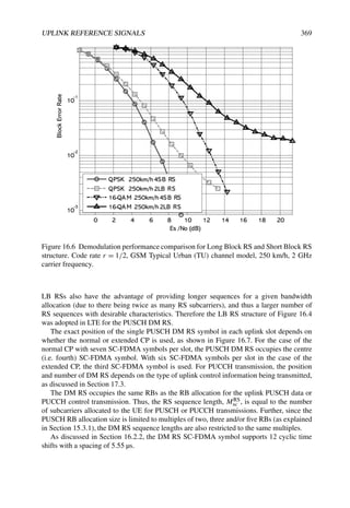
![370 LTE – THE UMTS LONG TERM EVOLUTION
CP LB#1
CP LB#0 CP LB#1
CP LB#1 CP LB#1
CP LB#2 CP
CP CP LB#1
CP LB#4 CP LB#1
CP LB#5 CP LB#1
CP LB#6
1 slot = 0.5ms
(a) Normal CP
(b) Extended CP
RS LB #3
CP LB#0 CP LB#1 CP RS LB#2 CP LB#3 CP LB#4 CP LB#5
Figure 16.7 LTE uplink subframe configuration for PUSCH DM RS: (a) normal CP;
(b) extended CP.
To support inter-cell interference randomization, cyclic time shift hopping is always
enabled for DM RS as detailed in Section 16.4.
16.6 Uplink Sounding Reference Signals (SRS)
The SRS, which are not associated with uplink data and/or control transmission, are primarily
used for channel quality estimation to enable frequency-selective scheduling on the uplink.
However, they can be used for other purposes such as to enhance power control or to
support various start-up functions for UEs not recently scheduled. Some examples include
initial Modulation and Coding Scheme (MCS) selection, initial power control for data
transmissions, timing advance, and so-called frequency semi-selective scheduling in which
the frequency resource is assigned selectively for the first slot of a subframe and hops pseudo-
randomly to a different frequency in the second slot [14].
16.6.1 SRS Subframe Configuration and Position
The subframes in which SRS are transmitted by any UE within the cell are indicated by
cell-specific broadcast signalling. A 4-bit cell-specific ‘srsSubframeConfiguration’parameter
indicates 15 possible sets of subframes in which SRS may be transmitted within each
radio frame (see reference [4], Section 5.5.3.3). This configurability provides flexibility in
adjusting the SRS overhead depending on the deployment scenario. A 16th configuration
switches the SRS off completely in the cell, which may for example be appropriate for a cell
serving primarily high-speed UEs.
The SRS transmissions are always in the last SC-FDMA symbol in the configured
subframes, as shown in Figure 16.8. Thus the SRS and DM RS are located in different
SC-FDMA symbols. PUSCH data transmission is not permitted on the SC-FDMA symbol
CP
LB#1
CP
LB#2
CP
LB#3
CP
LB#5
CP
LB#6
CP
LB#7
CP
LB#8
CP
LB#9
CP
LB#10
CP
LB#12
CP
LB#13
CP
LB#4,
RS
CP
LB#11
RS
CP
LB#14
SRS
subframe = 1 ms
slot 0 = 0.5 ms slot 1 = 0.5 ms
Figure 16.8 Uplink subframe configuration with SRS symbol.](https://image.slidesharecdn.com/ltefromtheorytopractise-240124145854-b0067765/85/LTE_from_Theory_to_Practise-pdf-394-320.jpg)
![UPLINK REFERENCE SIGNALS 371
designated for SRS, resulting in a worst-case sounding overhead (with an SRS symbol in
every subframe) of ∼7%.
16.6.2 Duration and Periodicity of SRS Transmissions
The eNodeB in LTE may either request an individual SRS transmission from a UE or
configure a UE to transmit SRS periodically until terminated; a 1-bit UE-specific signalling
parameter, ‘duration’, indicates whether the requested SRS transmission is single or periodic.
If periodic SRS transmissions are configured for a UE, the periodicity may be any of 2, 5, 10,
20, 40, 80, 160 or 320 ms; the SRS periodicity and SRS subframe offset within the period
in which the UE should transmit its SRS are configured by a 10-bit UE-specific dedicated
signalling parameter called ‘srsConfigurationIndex’.
16.6.3 SRS Symbol Structure
In order to support frequency-selective scheduling between multiple UEs, it is necessary
that SRS from different UEs with different sounding bandwidths can overlap. In order to
support this, Interleaved FDMA (IFDMA, introduced in Section 15.2) is used in the SRS SC-
FDMA symbol, with a RePetition Factor (RPF) of 2. The (time-domain) RPF is equivalent
to a frequency-domain decimation factor, giving the spacing between occupied subcarriers
of an SRS signal with a comb-like spectrum. Thus, RPF = 2 implies that the signal occupies
every 2nd subcarrier within the allocated sounding bandwidth as shown by way of example
in Figure 16.9. Using a larger RPF could in theory have provided more flexibility in how the
bandwidth could be allocated between UEs, but it would have reduced the sounding sequence
length (for a given sounding bandwidth) and the number of available SRS sequences (similar
to the case for DM RS), and therefore the RPF was limited to 2 in LTE.
Due to the IFDMA structure of the SRS symbol, a UE is assigned, as part of its
configurable SRS parameters, the ‘transmissionComb’ index (0 or 1) on which to transmit
the SRS. The RS sequences used for the SRS are the same as for the DM RS, resulting in
the SRS sequence length being restricted to multiples of two, three and/or five times the
resource block size. In addition, the SRS bandwidth (in RBs) must be an even number, due to
the RPF of 2 and the minimum SRS sequence length being 12. Therefore, the possible SRS
bandwidths, NSRS
RB (in number of RBs), and the SRS sequence length, MSRS
sc , are respectively
given by,
NSRS
RB = 2(1+α2)
· 3α3 · 5α5
MSRS
sc = 1
2 · NSRS
RB · 12 (16.8)
where α2, α3, α5 is a set of positive integers. Similarly to the DM RS, simultaneous SRS
can be transmitted from multiple UEs using the same RBs and the same offset of the comb,
using different cyclic time shifts of the same base sequence to achieve orthogonal separation
(see Section 16.2.2). For the SRS, eight (evenly-spaced) cyclic time shifts per SRS-comb are
supported (see [4], Section 5.5.3.1), with the cyclic shift being configured individually for
each UE.](https://image.slidesharecdn.com/ltefromtheorytopractise-240124145854-b0067765/85/LTE_from_Theory_to_Practise-pdf-395-320.jpg)

![UPLINK REFERENCE SIGNALS 373
Table 16.1 Sounding RS BandWidth (BW) configurations for system bandwidths 40–60
RBs. (See [4], Table 5.5.3.2-2.) Reproduced by permission of © 3GPP.
SRS BW SRS-BW SRS-BW SRS-BW SRS-BW
configuration 0 1 2 3
0 48 24 12 4
1 48 16 8 4
2 40 20 4 4
3 36 12 4 4
4 32 16 8 4
5 24 4 4 4
6 20 4 4 4
7 16 4 4 4
defined for each possible system bandwidth. RRC signalling indicates which of the eight sets
is applicable in the cell by means of a 3-bit cell-specific parameter ‘srsBandwidthConfigura-
tion’. This allows some variability in the maximum SRS bandwidths, which is important as
the SRS region does not include the PUCCH region near the edges of the system bandwidth
(see Section 17.3), which is itself variable in bandwidth. An example of the eight sets of four
SRS bandwidths applicable to uplink system bandwidths in the range 40–60 RBs is shown in
Table 16.1 (see [4], Table 5.5.3.2-2).
The specific SRS bandwidth to be used by a given UE is configured by a further 2-bit
UE-specific parameter, ‘srsBandwidth’.
As can be seen from Table 16.1, the smallest sounding bandwidth supported is 4 RBs.
A small sounding bandwidth of 4 RBs provides for higher-quality channel information
from a power-limited UE. The sounding bandwidths are constrained to be multiples of
each other, i.e. following a tree-like structure, to support frequency hopping of the different
narrowband SRS bandwidths (see Section 5.5.3.2 of reference [4]). Frequency hopping
can be enabled or disabled for an individual UE based on the value of the parameter
‘frequencyDomainPosition’. The tree structure of the SRS bandwidths limits the possible
starting positions for the different SRS bandwidths, reducing the overhead for signalling
the starting position to 5 bits (signalled to each UE by the parameter ‘Frequency-domain
position’.
Table 16.2 summarizes the various SRS configurable parameters which are signalled to a
UE [15].
16.7 Summary
The uplink reference signals provided in LTE fulfil an important function in facilitating
channel estimation and channel sounding. The ZC-based sequence design can be seen to
be a good match to this role, with constant amplitude in the frequency domain and the
ability to provide a large number of sequences with zero or low correlation. This enables both
interference randomization and interference coordination techniques to be employed in LTE
system deployments, as appropriate to the scenario. A high degree of flexibility is provided
for configuring the reference signals, especially for the sounding reference signals, where](https://image.slidesharecdn.com/ltefromtheorytopractise-240124145854-b0067765/85/LTE_from_Theory_to_Practise-pdf-397-320.jpg)
![374 LTE – THE UMTS LONG TERM EVOLUTION
Table 16.2 UL sounding RS configurable parameters.
Sounding RS parameter name Significance Signalling type
srsBandwidthConfiguration Maximum SRS bandwidth in
the cell
Cell-specific
srsSubframeConfiguration Sets of subframes in which
SRS may be transmitted in the
cell
Cell-specific
srsBandwidth SRS transmission bandwidth
for a UE
UE-specific
frequencyDomainPosition Frequency-domain position UE-specific
srsHoppingBandwidth Frequency hop size UE-specific
duration Single SRS or periodic UE-specific
srsConfigurationIndex Periodicity and subframe offset UE-specific
transmissionComb Transmission comb offset UE-specific
ncs
SRS Cyclic shift UE-specific
the overhead arising from their transmission can be traded off against the improvements in
system efficiency which may be achievable from frequency-selective uplink scheduling.
References5
[1] D. C. Chu, ‘Polyphase Codes With Good Periodic Correlation Properties’. IEEE Trans. on
Information Theory, pp. 531–532, July 1972.
[2] B. M Popovic, ‘Generalized Chirp-like Polyphase Sequences with Optimal Correlation
Properties’. IEEE Trans. on Information Theory, Vol. 38, pp. 1406–1409, July 1992.
[3] Motorola, ‘R1-060878: EUTRA SC-FDMA Uplink Pilot/Reference Signal Design TP’,
www.3gpp.org, 3GPP TSG RAN WG1, meeting 44bis, Athens, Greece, March 2006.
[4] 3GPP Technical Specification 36.211, ‘Evolved Universal Terrestrial Radio Access (E-UTRA);
Physical channels and modulation (Release 8)’, www.3gpp.org.
[5] Huawei, LG Electronics, NTT DoCoMo, and Panasonic, ‘R1-080576: Way Forward on the
Sequence Grouping for UL DM RS’, www.3gpp.org, 3GPP TSG RAN WG1, meeting 51bis,
Sevilla, Spain, January 2008.
[6] K. Fazel and G. P. Fettweis, Multi-Carrier Spread-Spectrum. Kluwer Academic Publishers,
Dordrecht, Holland, 1997.
5All web sites confirmed 18th December 2008.](https://image.slidesharecdn.com/ltefromtheorytopractise-240124145854-b0067765/85/LTE_from_Theory_to_Practise-pdf-398-320.jpg)
![UPLINK REFERENCE SIGNALS 375
[7] Alcatel-Lucent, Ericsson, Freescale, Huawei, LGE, Motorola, Nokia, Nokia-Siemens Networks,
NTT DoCoMo, Nortel, Panasonic, Qualcomm, and TI, ‘R1-072584: Way Forward for PUSCH
RS’, www.3gpp.org, 3GPP TSG RAN WG1, meeting 49, Kobe, Japan, May 2007.
[8] Alcatel-Lucent, Ericsson, Freescale, Huawei, LGE, Motorola, Nokia, Nokia-Siemens Networks,
NTT DoCoMo, Nortel, Panasonic, Qualcomm, and TI, ‘R1-072585: Way forward for PUCCH
RS’, www.3gpp.org, 3GPP TSG RAN WG1, meeting 49, Kobe, Japan, May 2007.
[9] NTT DoCoMo, ‘R1-074278: Hopping and Planning of Sequence Groups for Uplink RS’,
www.3gpp.org, 3GPP TSG RAN WG1, meeting 50bis, Shanghai, China, October 2007.
[10] Motorola, ‘R1-080719: Hopping Patterns for UL RS’, www.3gpp.org, 3GPP TSG RAN WG1,
meeting 52, Sorrento, Italy, February 2008.
[11] Qualcomm Europe, Ericsson, Motorola, Samsung, Panasonic, and NTT DoCoMo, ‘R1-081133:
WF on UL DM-RS Hopping Pattern Generation’, www.3gpp.org, 3GPP TSG RAN WG1, meeting
52, Sorrento, Italy, February 2008.
[12] Motorola, ‘R1-071341: Uplink Reference Signal Planning Aspects’, www.3gpp.org, 3GPP TSG
RAN WG1, meeting 48bis, St. Julian’s, Malta, March 2007.
[13] Panasonic, Samsung, and ETRI, ‘R1-080983: Way forward on the Cyclic Shift Hopping for
PUCCH’, www.3gpp.org, 3GPP TSG RAN WG1, meeting 52, Sorrento, Italy, February 2008.
[14] Motorola, ‘R1-073756: Benefit of Non-Persistent UL Sounding for Frequency Hopping PUSCH’,
www.3gpp.org, 3GPP TSG RAN WG1, meeting 50, Athens, Greece, August 2007.
[15] Ericsson, ‘R1-082199: Physical-layer parameters to be configured by RRC’, www.3gpp.org,
3GPP TSG RAN WG1, meeting 53, Kansas City, USA, May 2008.](https://image.slidesharecdn.com/ltefromtheorytopractise-240124145854-b0067765/85/LTE_from_Theory_to_Practise-pdf-399-320.jpg)

![378 LTE – THE UMTS LONG TERM EVOLUTION
PRACH PUSCH
CCCH DCCH DTCH
Uplink
Logical Channels
Uplink
Transport Channels
Uplink
Physical Channels
RACH UL-SCH
MAC LAYER
PHY LAYER
PUCCH
Figure 17.1 Summary of uplink physical channels and mapping to higher layers.
17.2 Uplink Shared Data Channel Structure
The Physical Uplink Shared CHannel (PUSCH), which carries data from the Uplink
Shared Channel (UL-SCH) transport channel, uses DFT-Spread OFDM (DFT-S-OFDM),
as described in Chapter 15. The transmit processing chain is shown in Figure 17.2. As
explained in Chapter 10, the information bits are first channel-coded with a turbo code of
mother code rate r = 1/3, which is adapted to a suitable final code rate by a rate-matching
process. This is followed by symbol-level channel interleaving which follows a simple ‘time-
first’ mapping [1] – in other words, adjacent data symbols end up being mapped first to
adjacent SC-FDMA symbols in the time domain, and then across the subcarriers (see [2],
Section 5.2.2.8). The coded and interleaved bits are then scrambled by a length-31 Gold code
(as in Section 6.3) prior to modulation mapping, DFT-spreading, subcarrier mapping1 and
OFDM modulation. The signal is frequency-shifted by half a subcarrier prior to transmission,
to avoid the distortion caused by the d.c. subcarrier being concentrated in one RB, as
described in Section 15.3.3. The modulations supported are QPSK, 16QAM and 64QAM
(the latter being only for the highest category of User Equipment (UE)).
The baseband SC-FDMA transmit signal for SC-FDMA symbol is thus of the form
(see [3], Section 5.6),
s (t) =
k=−NUL
RB NRB
sc /2−1
k=−NUL
RB NRB
sc /2
ak−, exp[j2π(k + 1/2)f (t − NCP, Ts)] (17.1)
for 0 ≤ t (NCP, + N)Ts, where NCP, is the number of samples of the Cyclic Prefix
(CP) in SC-FDMA symbol (see Section 15.3), N = 2048 is the Inverse Fast Fourier
1Only localized mapping (i.e. to contiguous blocks of subcarriers) is supported for PUSCH and PUCCH
transmissions in LTE.](https://image.slidesharecdn.com/ltefromtheorytopractise-240124145854-b0067765/85/LTE_from_Theory_to_Practise-pdf-401-320.jpg)
![UPLINK PHYSICAL CHANNEL STRUCTURE 379
Figure 17.2 Uplink physical data channel processing.
Transform (IFFT) size, f = 15 kHz is the subcarrier spacing, Ts = 1/(N · f ) is the
sampling interval, NUL
RB is the uplink system bandwidth in RBs, NRB
sc = 12 is the number of
subcarriers per resource block, k(−) = k + NUL
RB NRB
sc /2 and ak, is the content of subcarrier
k on symbol . For PUSCH data SC-FDMA symbols, ak, is obtained by DFT-spreading
the data QAM symbols, [d0, , d1, , . . . , dMPUSCH
SC −1, ] to be transmitted on data SC-FDMA
symbol (see [3], Section 5.3.3),
ak, =
1
!
MPUSCH
sc
MPUSCH
sc −1
i=0
di, e−j2πik/MPUSCH
sc (17.2)
for k = 0, 1, 2, . . . , MPUSCH
sc − 1, where MPUSCH
sc = MPUSCH
RB · NRB
sc and MPUSCH
RB is the
allocated PUSCH bandwidth in RBs.
As explained in Section 4.4.1, a Hybrid Automatic Repeat reQuest (HARQ) scheme
is used, which in the uplink is synchronous, using N-channel stop and wait. This means
that retransmissions occur in specific periodically-occurring subframes (HARQ channels).
Further details of the HARQ operation are given in Section 10.3.2.5.
17.2.1 Scheduling Supported in LTE SC-FDMA Uplink
In the LTE uplink, both frequency-selective scheduling and non-frequency-selectiveschedul-
ing are supported. The former is based on the eNodeB exploiting available channel
knowledge to schedule a UE to transmit using specific Resource Blocks (RBs) in the
frequency domain where the channel response is good. The latter does not make use of
frequency-specific channel knowledge, but rather aims to benefit from frequency diversity
during the transmission of each transport block. The possible techniques supported in LTE
are discussed in more detail below. Intermediate approaches are also possible.
17.2.1.1 Frequency-Selective Scheduling
With frequency-selectivescheduling, the same localized2 allocation of transmission resources
is typically used in both slots of a subframe – there is no frequency hopping during a
subframe. The frequency-domain RB allocation and the Modulation and Coding Scheme
(MCS) are chosen based on the location and quality of an above-average gain in the uplink
2Localized means that allocated RBs are consecutive in the frequency domain.](https://image.slidesharecdn.com/ltefromtheorytopractise-240124145854-b0067765/85/LTE_from_Theory_to_Practise-pdf-402-320.jpg)
![380 LTE – THE UMTS LONG TERM EVOLUTION
channel response [4]. In order to enable frequency-selective scheduling, timely channel
quality information is needed at the eNodeB. One method for obtaining such information in
LTE is by uplink channel sounding using the SRS described in Section 16.6. The performance
of frequency-selective scheduling using the SRS depends on the sounding bandwidth and the
quality of the channel estimate, the latter being a function of the transmission power spectral
density used for the SRS. With a large sounding bandwidth, link quality can be evaluated
on a larger number of RBs. However, this is likely to lead to the SRS being transmitted
at a lower power density, due to the limited total UE transmit power, and this reduces the
accuracy of the estimate for each RB within the sounding bandwidth. Conversely, sounding a
smaller bandwidth can improve channel estimation on the sounded RBs but results in missing
channel information for certain parts of the channel bandwidth, thus risking exclusion of
the best quality RBs. As an example, experiments performed in reference [5] show that at
least for a bandwidth of 5 MHz, frequency-selective scheduling based on full-band sounding
outperforms narrower bandwidth sounding.
17.2.1.2 Frequency-Diverse or Non-Selective Scheduling
There are cases when no, or limited, frequency-specific channel quality information is
available, for example because of SRS overhead constraints or high Doppler conditions. In
such cases, it is preferable to exploit the frequency diversity of LTE’s wideband channel.
In LTE, frequency hopping of a localized transmission is used to provide frequency-
diversity. Two hopping modes are supported – hopping only between subframes (inter-
subframe hopping), or hopping both between and within subframes (inter- and intra-subframe
hopping). These modes are illustrated in Figure 17.3. Cell-specific broadcast signalling is
used to configure the hopping mode (see [6], Section 8.4).
In case of intra-subframe hopping, a frequency hop occurs at the slot boundary in the
middle of a subframe; this provides frequency diversity within a codeword (i.e. within a
single transmission of transport block). On the other hand, inter-subframe hopping provides
frequency diversity between HARQ retransmissions of a transport block, as the frequency
allocation hops every allocated subframe.
Two methods are defined for the frequency hopping allocation (see [6], Section 8.4):
either a pre-determined pseudo-random frequency hopping pattern (see reference [3],
Section 5.3.4), or an explicit hopping offset signalled in the UL resource grant on the
PDCCH. For uplink system bandwidths less than 50 RBs, the size of the hopping offset
(modulo the system bandwidth) is approximately half the number of RBs available for
PUSCH transmissions (i.e. NPUSCH
RB /2), while for uplink system bandwidths of 50 RBs
or more, the possible hopping offsets are NPUSCH
RB /2, and ±NPUSCH
RB /4 (see [6],
Section 8.4).
Signalling the frequency hop via the uplink resource grant can be used for frequency semi-
selective scheduling [7], in which the frequency resource is assigned selectively for the first
slot of a subframe and frequency diversity is also achieved by hopping to a different frequency
in the second slot. In some scenarios this may yield intermediate performance between that
of fully frequency-selective and fully non-selective scheduling; this may be seen as one way
to reduce the sounding overhead typically needed for fully frequency-selective scheduling.](https://image.slidesharecdn.com/ltefromtheorytopractise-240124145854-b0067765/85/LTE_from_Theory_to_Practise-pdf-403-320.jpg)

![382 LTE – THE UMTS LONG TERM EVOLUTION
When simultaneous uplink PUSCH data and control signalling is scheduled for a UE, the
control signalling is multiplexed together with the data prior to the DFT spreading, in order to
preserve the single-carrier low-Cubic Metric (CM) property of the uplink transmission. The
uplink control channel, PUCCH, is used by a UE to transmit any necessary control signalling
only in subframes in which the UE has not been allocated any RBs for PUSCH transmission.
In the design of the PUCCH, special consideration was given to maintaining a low CM [8].
17.3.1 Physical Uplink Control Channel (PUCCH) Structure
The control signalling on the PUCCH is transmitted in a frequency region on the edges of
the system bandwidth.
In order to minimize the resources needed for transmission of control signalling, the
PUCCH in LTE is designed to exploit frequency diversity: each PUCCH transmission in one
subframe is comprised of a single (0.5 ms) RB at or near one edge of the system bandwidth,
followed (in the second slot of the subframe) by a second RB at or near the opposite edge
of the system bandwidth, as shown in Figure 17.5; together, the two RBs are referred to as a
PUCCH region. This design can achieve a frequency diversity benefit of approximately 2 dB
compared to transmission in the same RB throughout the subframe.
At the same time, the narrow bandwidth of the PUCCH in each slot (only a single
resource block) maximizes the power per subcarrier for a given total transmission power
(see Figure 17.4), and therefore helps to fulfil stringent coverage requirements.
Figure 17.4 The link budget of a two-slot narrowband transmission exceeds that of a one-slot
wider-band transmission, given equal coding gain.
Positioning the control regions at the edges of the system bandwidth has a number of
advantages, including the following:
• The frequency diversity achieved through frequency hopping is maximized by allowing
hopping from one edge of the band to the other.
• Out-Of-Band (OOB) emissions are smaller if a UE is only transmitting on a single
RB per slot compared to multiple RBs. The PUCCH regions can therefore serve as a
kind of guard band between the wider-bandwidth PUSCH transmissions of adjacent
carriers, and therefore can improve coexistence [9].](https://image.slidesharecdn.com/ltefromtheorytopractise-240124145854-b0067765/85/LTE_from_Theory_to_Practise-pdf-405-320.jpg)


![UPLINK PHYSICAL CHANNEL STRUCTURE 385
SC-FDMA symbol. As the PUCCH RB spans 12 subcarriers, and assuming the channel is
approximately constant over the RB (i.e. a single-tap channel), the LTE PUCCH supports up
to 12 cyclic shifts per PUCCH RB.
For control information transmissions with a small number of control signalling bits, such
as 1- or 2-bit positive/negative acknowledgments (ACK/NACK), orthogonality is achieved
between UEs by a combination of cyclic time shifts within an SC-FDMA symbol and SC-
FDMA symbol time-domain spreading with orthogonal spreading codes, i.e. modulating the
SC-FDMA symbols by elements of an orthogonal spreading code [10]. CDM of multiple
UEs is used rather than Time Domain Multiplexing (TDM) because CDM enables the time
duration of the transmission to be longer, which increases the total transmitted energy per
signalling message in the case of a power-limited UE.
Thus, the LTE PUCCH control structure uses frequency-domain code multiplexing
(different cyclic time shifts of a base sequence) and/or time-domain code multiplexing
(different orthogonal block spreading codes), thereby providing an efficient, orthogonal
control channel which supports small payloads (up to 22 coded bits) from multiple UEs
simultaneously, together with and good operational capability at low SNR.
17.3.1.2 Control Signalling Information Carried on PUCCH
The control signalling information carried on the PUCCH can consist of:
• Scheduling Requests (SRs) (see Section 4.4.2.2).
• HARQ ACK/NACK in response to downlink data packets on (PDSCH). One ACK/
NACK bit is transmitted in case of single codeword downlink transmission while two
ACK/NACK bits are used in case of two codeword downlink transmission.
• CQI, which for the purposes of control signalling categorization, is taken to include
the MIMO-related feedback consisting of RIs and PMI. 20 bits per subframe are used
for the CQI.
The amount of control information which a UE can transmit in a subframe depends
on the number of SC-FDMA symbols available for transmission of control signalling data
(i.e. excluding SC-FDMA symbols used for reference signal transmission for coherent
detection of the PUCCH). The PUCCH supports seven different formats depending on
the information to be signalled. The mapping between the PUCCH format and the Uplink
Control Information (UCI) supported in LTE is shown in Table 17.2 (see [6] Section 10.1, [3]
Table 5.4-1).
The physical mapping of the PUCCH formats to the PUCCH regions is shown in
Figure 17.7.
It can be seen that the PUCCH CQI formats 2/2a/2b are mapped and transmitted on the
band-edge RBs (e.g. PUCCH region m = 0, 1) followed by a mixed PUCCH RB (if present,
e.g. region m = 2) of CQI format 2/2a/2b and SR/HARQ ACK/NACK format 1/1a/1b, and
then by PUCCH SR/HARQ ACK/NACK format 1/1a/1b (e.g. region m = 4, 5). The number
of PUCCH RBs available for use by CQI format 2/2a/2b, N2
RB, is indicated to the UEs in the
cell by broadcast signalling.](https://image.slidesharecdn.com/ltefromtheorytopractise-240124145854-b0067765/85/LTE_from_Theory_to_Practise-pdf-408-320.jpg)

![UPLINK PHYSICAL CHANNEL STRUCTURE 387
LB#0
C
P
RS LB
C
P
LB#2
C
P
LB#3
C
P
LB#4
C
P
RS LB
C
P
LB#6
C
P
IFFT
Cyclic Shift,
cs,1
ru,0
1
ru,0
length-12
IFFT
Cyclic Shift,
cs,5
ru,0
5
IFFT
Cyclic Shift,
cs,0
IFFT
Cyclic Shift,
cs,2
IFF T
Cyclic Shift ,
cs,4
IFFT
Cyclic Shift,
cs,6
ru,0
length-12
d0
d0 ru,0
1
d1 ru,0
2 d4 ru,0
6
IFFT
Cyclic Shift,
cs,3
QPSK
Mod.
Serial-to-Parallel
Coded CQI bits
(10 bits)
ru,0
length-12
ru,0
length-12
ru,0
length-12
ru,0
length-12
d1 d2 d3
d4
d2 ru,0
3
d3 ru,0
4
Figure 17.8 CQI channel structure for PUCCH format 2/2a/2b with normal CP for one slot.
considered to provide the best trade-off in terms of performance and RS overhead, given the
payload sizes required.
10 CQI information bits are channel coded with a rate 1/2 punctured (20, k) Reed–Muller
code (see reference [2], Section 5.2.3.3) to give 20 coded bits, which are then scrambled (in
a similar way to PUSCH data with a length-31 Gold sequence) prior to QPSK constellation
mapping. One QPSK modulated symbol is transmitted on each of the 10 SC-FDMA symbols
in the subframe by modulating a cyclic time shift of the base RS sequence of length-12 prior
to OFDM modulation. The 12 equally-spaced cyclic time shifts allow 12 different UEs to be
orthogonally multiplexed on the same CQI PUCCH RB.
The DM RS signal sequence (on the 2nd and 6th SC-FDMA symbols for the normal CP, or
the 4th symbol for the extended CP) is similar to the frequency domain CQI signal sequence
but without the CQI data modulation.
In order to provide inter-cell interference randomization, cell-specific symbol-level cyclic
time shift hopping is used, as described in Section 16.4. For example, the PUCCH cyclic
time shift index on SC-FDMA symbol l in even slots ns is obtained by adding (modulo-12)](https://image.slidesharecdn.com/ltefromtheorytopractise-240124145854-b0067765/85/LTE_from_Theory_to_Practise-pdf-410-320.jpg)
![388 LTE – THE UMTS LONG TERM EVOLUTION
a pseudo-random cell-specific PUCCH cyclic shift offset to the assigned cyclic time shift
nPUCCH
RS . Intra-cell interference randomization is achieved by cyclic time shift remapping in
the second slot as explained in Section 16.4.
A UE is semi-statically configured by higher layer signalling to report periodically differ-
ent CQI, PMI, and RI types (see Section 10.2.1) on CQI PUCCH using a PUCCH resource
index n(2)
PUCCH, which indicates both the PUCCH region and the cyclic time shift to be used.
The PUCCH region m used for the PUCCH format 2/2a/2b transmission (see Figure 17.7),
is given by (see [3], Section 5.4.3)
m =
#
n(2)
PUCCH
12
$
(17.3)
and the assigned cyclic time shift, nPUCCH
RS , is given by
nPUCCH
RS = n
(2)
PUCCH mod 12 (17.4)
17.3.3 Multiplexing of CQI and HARQ ACK/NACK from a UE on
PUCCH
In LTE, the simultaneous transmission of HARQ ACK/NACK and CQI by a UE can be
enabled by UE-specific higher layer signalling. In case simultaneous transmission is not
enabled, and the UE needs to transmit HARQ ACK/NACK on the PUCCH in the same
subframe in which a CQI report has been configured, the CQI is dropped and only HARQ
ACK/NACK is transmitted using the transmission structure detailed in Section 17.3.4.
In subframes where the eNodeB scheduler allows for simultaneous transmission of CQI
and HARQ ACK/NACK from a UE, the CQI and the 1- or 2-bit HARQ ACK/NACK
information needs to be multiplexed in the same PUCCH RB, while maintaining the low
CM single carrier property of the signal. The method used to achieve this is different for the
case of normal CP and extended CP as described in the following sections.
17.3.3.1 Multiplexing of CQI and HARQ ACK/NACK – Normal CP (Format 2a/2b)
The transmission structure for CQI data is the same as described in Section 17.3.2. In
order to transmit a 1- or 2-bit HARQ ACK/NACK together with CQI (Format 2a/2b), the
HARQ ACK/NACK bits (which are not scrambled) are BPSK/QPSK modulated as shown
in Figure 17.9, resulting in a single HARQ ACK/NACK modulation symbol, dHARQ. A
positive acknowledgement(ACK) is encoded as a binary ‘1’ and a negative acknowledgement
(NACK) is encoded as a binary ‘0’ (see [2], Section 5.2.3.4).
The single HARQ ACK/NACK modulation symbol, dHARQ, is then used to modulate the
second RS symbol (SC-FDMA symbol 5) in each CQI slot – i.e. ACK/NACK is signalled
using the RS. It can be seen from Figure 17.9 that the modulation mapping is such that
a NACK (or NACK, NACK in the case of two downlink MIMO codewords) is mapped
to +1, resulting in a default NACK in case neither ACK nor NACK is transmitted (so-
called Discontinuous Transmission (DTX)), as happens if the UE fails to detect the downlink
grant on the Physical Downlink Control CHannel (PDCCH). In other words, a DTX (no RS
modulation) is interpreted as a NACK by the eNodeB, triggering a downlink retransmission.](https://image.slidesharecdn.com/ltefromtheorytopractise-240124145854-b0067765/85/LTE_from_Theory_to_Practise-pdf-411-320.jpg)
![UPLINK PHYSICAL CHANNEL STRUCTURE 389
ACK=1 DTX/NACK=0
BPSK
PUCCH Format 2a
-1 +1
DTX/(NACK,NACK)=00
+1
(ACK,ACK)=11
(ACK,NACK)=10
(NACK,ACK)=01
QPSK
PUCCH Format 2b
+j
-j
Figure 17.9 Constellation mapping for HARQ ACK/NACK.
As the one of the RS in a CQI slot is modulated by the HARQ ACK/NACK modulation
symbol, some different ACK/NACK and CQI detection schemes are possible. In low-
Doppler environments with little channel variation over the 0.5 ms slot, coherent detection
of ACK/NACK and CQI can be achieved by using only the first RS symbol in the slot as the
phase reference. Alternatively, to improve the channel estimation quality for CQI detection,
an estimate of the HARQ ACK/NACK symbol can be used to undo the modulation on the
second RS in the slot so that both RS symbols can be used for channel estimation and
demodulation of CQI. In high-Doppler environments in which significant channel variations
occur over a slot, relying on a single RS symbol for coherent detection degrades performance
of ACK/NACK and CQI. In such cases blind decoding or multiple hypothesis testing of
the different ACK/NACK combinations can be used to decode the ACK/NACK and CQI,
selecting the hypothesis that maximizes the correlation between the received signal and the
estimated CQI information [11] (i.e. a Maximum Likelihood detection).
17.3.3.2 Multiplexing of CQI and HARQ ACK/NACK – Extended CP (Format 2)
In the case of the extended CP (with one RS symbol per slot), the 1- or 2-bit HARQ
ACK/NACK is jointly encoded with the CQI resulting in a (20, kCQI + kACK/NACK) Reed–
Muller based block code. A 20-bit codeword is transmitted on the PUCCH using the
CQI channel structure in Section 17.3.2. The joint coding of the ACK/NACK and CQI is
performed as shown in Figure 17.10. The largest number of information bits supported by
the block code is 13, corresponding to kCQI = 11 CQI bits and kACK/NACK = 2 bits (for two-
codeword transmission in the downlink).](https://image.slidesharecdn.com/ltefromtheorytopractise-240124145854-b0067765/85/LTE_from_Theory_to_Practise-pdf-412-320.jpg)
![390 LTE – THE UMTS LONG TERM EVOLUTION
(20, KCQI + NACK/NACK)
PUNCTURED RM
CODE
ACK/NACK
CQI
ACK/NA K
C
Figure 17.10 Joint coding of HARQ ACK/NACK and CQI for extended CP.
17.3.4 HARQ ACK/NACK Transmission on PUCCH (Format 1a/1b)
The PUCCH channel structure for HARQ ACK/NACK transmission with no CQI is shown
in Figure 17.11 for one slot with normal CP. Three (two in case of extended CP) SC-FDMA
symbols are used in the middle of the slot for RS transmission, with the remaining four
SC-FDMA symbols being used for ACK/NACK transmission. Due to the small number of
ACK/NACK bits, three RS symbols are used to improve the channel estimation accuracy for
a lower SNR operating point than for the CQI structure in Section 17.3.2.
Both 1- and 2-bit acknowledgements are supported using BPSK and QPSK modulation
respectively. The HARQ ACK/NACK bits (which are not scrambled) are BPSK/QPSK
modulated according to the modulation mapping shown in Figure 17.9 (see [3], Table 5.4.1-1)
resulting in a single HARQ ACK/NACK modulation symbol. A positive ACK is encoded as
a binary ‘1’ and a negative ACK (NACK) as a binary ‘0’ (see [2], Section 5.2.3.4). The
modulation mapping is the same as the mapping for 1- or 2-bit HARQ ACK/NACK when
multiplexed with CQI for PUCCH formats 2a/2b.
As in the case of CQI transmission, the one BPSK/QPSK modulated symbol (which is
phase-rotated by 90 degrees in the second slot) is transmitted on each SC-FDMA data symbol
by modulating a cyclic time shift of the base RS sequence of length-12 (i.e. frequency-domain
CDM) prior to OFDM modulation. In addition, as mentioned in Section 17.3.1.1, time-
domain spreading with orthogonal (Walsh–Hadamard or DFT) spreading codes is used to
code-division-multiplexUEs. Thus, a large number of UEs (data and RSs) can be multiplexed
on the same PUCCH RB using frequency-domain and time-domain code multiplexing. The
RSs from the different UEs are multiplexed in the same way as the data SC-FDMA symbols.
For the cyclic time shift multiplexing, the number of cyclic time shifts supported in
an SC-FDMA symbol for PUCCH HARQ ACK/NACK RBs is configurable by a cell-
specific higher-layer signalling parameter PUCCH
shift ∈ {1, 2, 3}, indicating 12, 6, or 4 shifts
respectively (see [3], Section 5.4.1). The value selected by the eNodeB for PUCCH
shift can be
based on the expected delay spread in the cell.
For the time-domain spreading CDM, the number of supported spreading codes for
ACK/NACK data is limited by the number of RS symbols, as the multiplexing capacity of RS
is smaller than that of the data symbols due to smaller number of RS symbols. For example,
in the case of six supportable cyclic time shifts and three (or two) orthogonal time spreading
codes in case of normal (or extended) CP with three (or two) RS symbols, acknowledgments
from 18 (or 12) different UEs can be multiplexed within one PUCCH RB. The length-2](https://image.slidesharecdn.com/ltefromtheorytopractise-240124145854-b0067765/85/LTE_from_Theory_to_Practise-pdf-413-320.jpg)
![UPLINK PHYSICAL CHANNEL STRUCTURE 391
LB#0
C
P
LB#1
C
P
RS LB
C
P
RS LB
C
P
RS LB
C
P
LB#5
C
P
LB#6
C
P
IFFT
wRS,0
Cyclic Shift,
cs,2
ru,0
2
ru,0
length-12
IFFT
Cyclic Shift,
cs,3
ru,0
3
IFFT
Cyclic Shift,
cs,4
ru,0
4
wRS,1 wRS,2
IFFT
Cyclic Shift,
cs,0
w0
IFFT
Cyclic Shift,
cs,1
w1
IFFT
Cyclic Shift,
cs,5
w2
IFFT
Cyclic Shift,
cs,6
w3
ru,0
length-12
ACK/NACK
symbol, d0
d0 ru,0
1
d0 ru,0
1
d0 ru,0
5
d0 ru,0
6
Figure 17.11 ACK/NACK structure – users are multiplexed using different cyclic shifts and
time-domain spreading.
and length-4 orthogonal block spreading codes are based on Walsh–Hadamard codes, and
the length-3 spreading codes are based on DFT codes as shown in Table 17.3. A subset of
size-s orthogonal spreading codes of a particular length L (s ≤ L) is used depending on the
number of RS SC-FDMA symbols. For the normal CP with four data SC-FDMA symbols and
three supportable orthogonal time spreading codes (due to there being three RS symbols), the
indices 0, 1, 2 of the length-4 orthogonal spreading codes are used for the data time-domain
block spreading.
Similarly, for the extended CP case with four data SC-FDMA symbols but only two RS
symbols, orthogonal spreading code indices 0 and 2 of length-4 are used for the data block
spreading codes. For the length-4 orthogonal codes, the code sequences used are such that
subsets of the code sequences result in the minimum inter-code interference in high Doppler
conditions where generally the orthogonality between the code sequences breaks down [12].
Table 17.4 summarizes the time-domain orthogonal spreading code lengths (i.e. spreading](https://image.slidesharecdn.com/ltefromtheorytopractise-240124145854-b0067765/85/LTE_from_Theory_to_Practise-pdf-414-320.jpg)
![392 LTE – THE UMTS LONG TERM EVOLUTION
Table 17.3 Time-domain orthogonal spreading code sequences. Reproduced by permission
of © 3GPP.
Orthogonal code Length-2 Length-3 Length-4
sequence index Walsh–Hadamard DFT Walsh–Hadamard
0
2
+1 +1
3 2
+1 +1 +1
3 2
+1 +1 +1 +1
3
1
2
+1 −1
3 2
1 ej2π/3 ej4π/3
3 2
+1 −1 +1 −1
3
2 N/A
2
1 ej4π/3 ej2π/3
3 2
+1 −1 −1 +1
3
3 N/A N/A
2
+1 +1 −1 −1
3
Table 17.4 Spreading factors for time-domain orthogonal spreading codes for data and RS
for PUCCH formats 1/1a/1b for normal and extended CP.
Normal CP Extended CP
Data, NPUCCH
SF RS, NPUCCH
RS Data, NPUCCH
SF RS, NPUCCH
RS
Spreading factor 4 3 4 2
factors) for data and RS. The number of supportable orthogonal spreading codes is equal to
the number of RS SC-FDMA symbols, NPUCCH
RS .
It should be noted that it is possible for the transmission of HARQ ACK/NACK and SRS
to be configured in the same subframe. If this occurs, the eNodeB can also configure (by
cell-specific broadcast signalling) the way in which these transmissions are to be handled by
the UE. One option is for the ACK/NACK to take precedence over the SRS, such that the
SRS is not transmitted and only HARQ ACK/NACK is transmitted in the relevant subframe,
according to the PUCCH ACK/NACK structure in Figure 17.11. The alternative is for the
eNodeB to configure the UEs to use a shortened PUCCH transmission in such subframes,
whereby the last SC-FDMA symbol of the ACK/NACK (i.e. the last SC-FDMA symbol in
the second slot of the subframe is not transmitted; this is shown in Figure 17.12).
This maintains the low CM single-carrier property of the transmitted signal, by ensuring
that a UE never needs to transmit both HARQ ACK/NACK and SRS symbols simultaneously,
even if both signals are configured in the same subframe. If the last symbol of the
ACK/NACK is not transmitted in the second slot of the subframe, this is known as a shortened
PUCCH format, as shown in Figure 17.13.3 For the shortened PUCCH, the length of the time-
domain orthogonal block spreading code is reduced by one (compared to the first slot shown
in Figure 17.11). Hence, it uses the length-3 DFT basis spreading codes in Table 17.3 in place
of the length-4 Walsh–Hadamard codes.
The frequency-domain HARQ ACK/NACK signal sequence on data SC-FDMA symbol
n is defined in [3], Section 5.4.1.
3Note that configuration of SRS in the same subframe as CQI or SR is not valid. Therefore the shortened PUCCH
formats are only applicable for PUCCH formats 1a and 1b.](https://image.slidesharecdn.com/ltefromtheorytopractise-240124145854-b0067765/85/LTE_from_Theory_to_Practise-pdf-415-320.jpg)
![UPLINK PHYSICAL CHANNEL STRUCTURE 393
Figure 17.12 A UE may not simultaneously transmit on SRS and PUCCH or PUSCH,
in order to avoid violating the single-carrier nature of the signal. Therefore, a PUCCH or
PUSCH symbol may be punctured if SRS is transmitted.
The number of HARQ ACK/NACK resource indices N(1)
PUCCH, RB corresponding to cyclic-
time-shift/orthogonal-code combinations that can be supported in a PUCCH RB is given by
N
(1)
PUCCH, RB = c · P, c =
1
3 normal cyclic prefix
2 extended cyclic prefix
(17.5)
where P = 12/PUCCH
shift , and PUCCH
shift ∈ {1, 2, 3} is the number of equally spaced cyclic
time shifts supported.
As in the case of CQI (see Section 17.3.2), cyclic time shift hopping (described in
Section 16.4) is used to provide inter-cell interference randomization.
In the case of semi-persistently scheduled downlink data transmissions on the PDSCH
(see Section 4.4.2.1) without a corresponding downlink grant on the control channel
(PDCCH), the PUCCH ACK/NACK resource index n
(1)
PUCCH to be used by a UE is semi-
statically configured by higher layer signalling. This PUCCH ACK/NACK resource is used
for ACK/NACK transmission corresponding to initial HARQ transmission. For dynamically-
scheduled downlink data transmissions (including HARQ retransmissions for semi-persistent
data) on PDSCH (indicated by downlink assignment signalling on the PDCCH), the PUCCH
HARQ ACK/NACK resource index n(1)
PUCCH is implicitly determined based on the index of
the first Control Channel Element (CCE, see Section 9.3) of the downlink control assignment.
The PUCCH region m used for the HARQ ACK/NACK with format 1/1a/1b transmission
for the case with no mixed PUCCH region (shown in Figure 17.7), is given by [3],
Section 5.4.3
m =
#
n(1)
PUCCH
N(1)
PUCCH, RB
$
+ N
(2)
RB (17.6)](https://image.slidesharecdn.com/ltefromtheorytopractise-240124145854-b0067765/85/LTE_from_Theory_to_Practise-pdf-416-320.jpg)
![394 LTE – THE UMTS LONG TERM EVOLUTION
LB#0
C
P
LB#1
C
P
RS LB
C
P
RS LB
C
P
RS LB
C
P
LB#5
C
P
LB#6, SRS
C
P
IFFT
wRS,0
Cyclic Shift,
cs,2
ru,0
2
ru,0
length-12
IFFT
Cyclic Shift,
cs,3
ru,0
3
IFFT
Cyclic Shift,
cs,4
ru,0
4
wRS,1 wRS,2
IFFT
Cyclic Shift,
cs,0
w0
IFFT
Cyclic Shift,
cs,1
w1
IFFT
Cyclic Shift,
cs,5
w2
ru,0
length-12
ACK/NACK
symbol, d0
d0 ru,0
1
d0 ru,0
1
d0 ru,0
5
Figure 17.13 Shortened PUCCH ACK/NACK Structure when simultaneous SRS and
ACK/NACK is enabled in the cell.
where N(2)
RB is the number of RBs that are available for PUCCH formats 2/2a/2b and is a
cell-specific broadcast parameter (see [3], Section 5.4).
The PUCCH resource index n(1)(ns), corresponding to a combination of a cyclic time
shift and orthogonal code (nPUCCH
RS and noc), within the PUCCH region m in even slots is
given by
n(1)
(ns) = n(1)
PUCCH mod N(1)
PUCCH, RB for ns mod 2 = 0 (17.7)
The PUCCH resource index (nPUCCH
RS , noc) allocation within a PUCCH RB format 1/1a/1b,
is shown in Tables 17.5, 17.6, and 17.7, for PUCCH
shift ∈ {1, 2, 3} with 36, 18, and 12 resource
indices respectively for the normal CP case [13]. For the extended CP, with two time-domain
orthogonal spreading code sequences, only the first two columns of the orthogonal code](https://image.slidesharecdn.com/ltefromtheorytopractise-240124145854-b0067765/85/LTE_from_Theory_to_Practise-pdf-417-320.jpg)

![396 LTE – THE UMTS LONG TERM EVOLUTION
Table 17.7 PUCCH RB format 1/1a/1b resource index allocation, PUCCH
shift = 3, 12 resource
indices, normal CP.
Orthogonal code sequence index, noc
Cyclic shift index, nPUCCH
RS noc = 0 noc = 1 noc = 2
0 0
1 4
2 7
3 1
4 5
5 8
6 2
7
8
9 3
10 6
11 9
values within each SC-FDMA symbol can restore orthogonality at moderate delay spreads.
This can enhance the tracking of high Doppler channels [14].
In order to randomize intra-cell interference, PUCCH resource index remapping is used
in the second slot [15]. Index remapping includes both cyclic shift remapping and orthogonal
block spreading code remapping (similar to the case of CQI – see Section 17.3.2).
The PUCCH resource index remapping function in an odd slot is based on the PUCCH
resource index in the even slot of the subframe, as defined in [3, Section 5.4.1].
17.3.5 Multiplexing of CQI and HARQ ACK/NACK in the Same
PUCCH RB (Mixed PUCCH RB)
The multiplexing of CQI and HARQ ACK/NACK in different PUCCH RBs can in general
simplify the system. However, in the case of small system bandwidths such as 1.4 MHz the
control signalling overhead can become undesirably high with separate CQI and ACK/NACK
RB allocations (two out of a total of six RBs for control signalling in 1.4 MHz system
bandwidths). Therefore, multiplexing of CQI and ACK/NACK from different UEs in the
same mixed PUCCH RB is supported in LTE to reduce the total control signalling overhead.
The ZC cyclic time shift structure facilitates the orthogonal multiplexing of CQI and
ACK/NACK signals with different numbers of RS symbols. This is achieved by assigning
different sets of adjacent cyclic time shifts to CQI and ACK/NACK signals [16] as shown in
Table 17.8. As can be seen from this table, N
(1)
cs ∈ {0, 1, . . . , 7} cyclic time shifts are used
for PUCCH ACK/NACK formats 1/1a/1b in the mixed PUCCH RB case, where N
(1)
cs is a cell-
specific broadcast parameter (see [3], Section 5.4) restricted to integer multiples of PUCCH
shift .
A guard cyclic time shift is used between the ACK/NACK and CQI cyclic shift resources
to improve orthogonality and channel separation between UEs transmitting CQI and those
transmitting ACK/NACK. To avoid mixing of the cyclic time shifts for ACK/NACK and](https://image.slidesharecdn.com/ltefromtheorytopractise-240124145854-b0067765/85/LTE_from_Theory_to_Practise-pdf-419-320.jpg)
![UPLINK PHYSICAL CHANNEL STRUCTURE 397
Table 17.8 Multiplexing of ACK/NACK (format 1/1a/1b) and CQI (format 2/2a/2b) from
different UEs in the same (mixed) PUCCH RB by using different sets of cyclic time shifts.
Cyclic shift index Cyclic shift index allocation
0 Format 1/1a/1b (HARQ ACK/NACK, SR) cyclic shifts
1
2
.
.
.
N
(1)
cs
N
(1)
cs + 1 Guard cyclic shift
N
(1)
cs + 2 Format 2/2a/2b (CQI) cyclic shifts
.
.
.
10
11 Guard cyclic shift
CQI, the cyclic time shift (i.e. the PUCCH resource index remapping function) for the odd
slot of the subframe is not used; the same cyclic time shift as in the first slot of the subframe
is used.
17.3.6 Scheduling Request (SR) Transmission on PUCCH (Format 1)
The structure of the SR PUCCH format 1 is the same as that of the ACK/NACK PUCCH
format 1a/1b explained in Section 17.3.4, where a cyclic time shift of the base RS sequence
is modulated with time-domain orthogonal block spreading. The SR uses simple On–Off
keying, with the UE transmitting a SR with modulation symbol d(0) = 1 to request a PUSCH
resource (positive SR transmission), and transmitting nothing when it does not request to be
scheduled (negative SR).
Since the HARQ ACK/NACK structure is reused for the SR, different PUCCH resource
indices (i.e. different cyclic time shift/orthogonal code combinations) in the same PUCCH
region can be assigned for SR (Format 1) or HARQ ACK/NACK (Format 1a/1b) from
different UEs. This results in orthogonal multiplexing of SR and HARQ ACK/NACK in the
same PUCCH region. The PUCCH resource index to be used by a UE for SR transmission,
m(1)
PUCCH,SRI, is configured by UE-specific higher-layer signalling.
In case a UE needs to transmit a positive SR in the same subframe as a scheduled CQI
transmission, the CQI is dropped and only the SR is transmitted, in order to maintain the low
CM of the transmit signal. Similarly, in the case of simultaneous SR and SRS configuration,
the UE does not transmit SRS and transmits only SR (see [6], Section 8.2).
If an SR and ACK/NACK happen to coincide in the same subframe, the UE transmits
the ACK/NACK on the assigned SR PUCCH resource for a positive SR and transmits
ACK/NACK on its assigned ACK/NACK PUCCH resource in case of a negative SR (see [6],
Section 8.3). The constellation mapping for simultaneous HARQ ACK/NACK and SR is
shown in Figure 17.14.](https://image.slidesharecdn.com/ltefromtheorytopractise-240124145854-b0067765/85/LTE_from_Theory_to_Practise-pdf-420-320.jpg)
![398 LTE – THE UMTS LONG TERM EVOLUTION
ACK=1 DTX/NACK=0
BPSK
PUCCH format 1a
-1 +1
DTX/(NACK,NACK)=00
+1
(ACK,ACK)=11
(ACK,NACK)=10
(NACK,ACK)=01
QPSK
PUCCH format 1b
+j
-j
positive SR/
positive SR/
Figure 17.14 Constellation Mapping for ACK/NACK and SR for PUCCH format 1/1a/1b.
The modulation mapping is such that a NACK (or NACK, NACK in the case of two
downlink MIMO codewords) is mapped to +1 resulting in a default NACK in case of DTX.
This is similar to the case of multiplexing CQI and HARQ ACK/NACK for the normal CP
case as described in Section 17.3.3.1.
17.4 Multiplexing of Control Signalling and UL-SCH Data
on PUSCH
When control signalling is to be transmitted in a subframe in which the UE has been allocated
transmission resources for the PUSCH, the control signalling is multiplexed together with
the UL-SCH data prior to DFT-spreading, in order to preserve the low CM single-carrier
property; the PUCCH is never transmitted in the same subframe as the PUSCH. The
multiplexing of CQI/PMI, HARQ ACK/NACK, and RI with the PUSCH data symbols onto
uplink resource elements is shown in Figure 17.15.
The number of resource elements used for each of CQI/PMI, ACK/NACK and RI is based
on the MCS assigned for PUSCH and an offset parameter, CQI
offset, HARQ-ACK
offset , or RI
offset,
which is semi-statically configured by higher-layer signalling (see [2], Section 5.2.2.6). This
allows different code rates to be used for the control signalling. PUSCH data and control
information are never mapped to the same resource element. Control information is mapped
in such a way that control is present in both slots of the subframe. Since the eNodeB has
prior knowledge of uplink control signaling transmission, it can easily de-multiplex control
and data packets.
As shown in Figure 17.15, CQI/PMI resources are placed at the beginning of the UL-SCH
data resources and mapped sequentially to all SC-FDMA symbols on one subcarrier before
continuing on the next subcarrier. The UL-SCH data is rate-matched (see Section 10.3.2.4)](https://image.slidesharecdn.com/ltefromtheorytopractise-240124145854-b0067765/85/LTE_from_Theory_to_Practise-pdf-421-320.jpg)
![UPLINK PHYSICAL CHANNEL STRUCTURE 399
PUSCH data
PUSCH RS
CQI/PMI
Rank (RI)
1 subcarrier
slot 0 slot 1
1 ms
ACK/NACK
Figure 17.15 Multiplexing of control signalling with UL-SCH data.
around the CQI/PMI data. The same modulation order as UL-SCH data on PUSCH is used
for CQI/PMI. For small CQI and/or PMI report sizes up to 11 bits, a (32, k) block code,
similar to the one used for PUCCH, is used, with optional circular repetition of encoded data
(see [2], Section 5.2.2.6.4); no CRC is applied. For large CQI reporting modes ( 11 bits), an
8-bit CRC is attached and channel coding and rate matching is performed using the tail-biting
convolutional code as described in Chapter 10.
The HARQ ACK/NACK resources are mapped to SC-FDMA symbols, by puncturing
the UL-SCH PUSCH data. Positions next to the RS are used, so as to benefit from the best
possible channel estimation. The maximum amount of resource for HARQ ACK/NACK is 4
SC-FDMA symbols.
The coded RI symbols are placed next to the HARQ ACK/NACK symbol positions
irrespective of whether ACK/NACK is actually present in a given subframe. The modulation
of the 1- or 2-bit ACK/NACK or RI is such that the Euclidean distance of the modulation
symbols carrying ACK/NACK and RI is maximized (see [2], Section 5.2.2.6). The outermost
constellation points of the higher-order 16/64-QAM PUSCH modulations are used, resulting
in increased transmit power for ACK/NACK/RI relative to the average PUSCH data power.
The coding of the RI and CQI/PMI are separate, with the UL-SCH data being rate-matched
around the RI resource elements similarly to the case of CQI/PMI.
In the case of 1-bit ACK/NACK or RI, repetition coding is used. For the case of 2-bit
ACK/NACK/RI, a (3, 2) simplex code is used with optional circular repetition of the encoded
data (see [2], Section 5.2.2.6). The resulting code achieves the theoretical maximum values
of the minimum Hamming distance of the output codewords in an efficient way. The (3, 2)
simplex codeword mapping is shown in Table 17.9.](https://image.slidesharecdn.com/ltefromtheorytopractise-240124145854-b0067765/85/LTE_from_Theory_to_Practise-pdf-422-320.jpg)
![400 LTE – THE UMTS LONG TERM EVOLUTION
Table 17.9 (3, 2) Simplex code for 2-bit ACK/NACK and RI.
2-bit Information 3-bit Output
Bit Sequence Codeword
00 000
01 011
10 101
11 110
In LTE, control signalling (using QPSK modulation) can also be scheduled to be
transmitted on PUSCH without UL-SCH data. The control signalling (CQI/PMI, RI, and/or
HARQ ACK/NACK) are multiplexed prior to DFT-spreading, in order to preserve the
low CM single-carrier property. The multiplexing of HARQ ACK/NACK and RI with
the CQI/PMI QPSK symbols onto uplink resource elements is similar to that shown in
Figure 17.15. HARQ ACK/NACK is mapped to SC-FDMA symbols next to the RS, by
puncturing the CQI data and RI symbols, irrespective of whether ACK/NACK is actually
present in a given subframe. The number of resource elements used for each of ACK/NACK
and RI is based on a reference MCS for CQI/PMI and offset parameters, CQI
offset, HARQ-ACK
offset ,
or RI
offset. The reference CQI/PMI MCS is computed from the CQI payload size and resource
allocation. The channel coding and rate matching of the control signalling without UL-SCH
data is the same as that of multiplexing control with UL-SCH data as described above.
17.5 Multiple-Antenna Techniques
In the first version of LTE, simultaneous transmissions from multiple-transmit antennas of
a single UE are not supported. Only a single power-amplifier is assumed to be available at
the UE. However, LTE does support closed-loop antenna selection transmit diversity in the
uplink from UEs which have multiple transmit antennas.
LTE is also designed to support uplink SDMA, or Virtual Multi-User MIMO (MU-
MIMO), and this is discussed in more detail in Section 17.5.2.
17.5.1 Closed-Loop Switched Antenna Diversity
Uplink closed-loop antenna selection (for up to two transmit antennas) is supported as an
optional UE capability in LTE (see [17], Section 4.3.4.1).
If a UE signals that it supports uplink antenna selection, the eNodeB may take this
capability into consideration when configuring and scheduling the UE.4
If the eNodeB enables a UE’s closed-loop antenna selection capability, the SRS transmis-
sions then alternate between the transmit antennas in successive configured SRS transmission
subframes, irrespective of whether frequency hopping is enabled or disabled, except when the
UE is configured for a single one-shot SRS transmission (see [6], Section 8.2).
4Alternatively, the eNodeB may permit the UE to use open-loop antenna selection, in which case the UE is free to
determine which antenna to transmit from. This may be based on uplink-downlink channel reciprocity, for example
in the case of TDD operation (see Section 23.5.2.5.](https://image.slidesharecdn.com/ltefromtheorytopractise-240124145854-b0067765/85/LTE_from_Theory_to_Practise-pdf-423-320.jpg)
![UPLINK PHYSICAL CHANNEL STRUCTURE 401
Table 17.10 UE transmit antenna selection CRC mask. Reproduced by permission of
© 3GPP.
Antenna selection mask
UE transmit antenna selection xAS,0, xAS,1, . . . . . . . . . , xAS,15
UE transmit antenna 0 0, 0, 0, 0, 0, 0, 0, 0, 0, 0, 0, 0, 0, 0, 0, 0
UE transmit antenna 1 0, 0, 0, 0, 0, 0, 0, 0, 0, 0, 0, 0, 0, 0, 0, 1
17.5.1.1 PUSCH UE Antenna Selection Indication
When closed-loop antenna selection is enabled, the eNodeB indicates which antenna should
be used for the PUSCH by implicit coding in the uplink scheduling grant (Downlink Control
Information (DCI) Format 0 – see Section 9.3): the 16 CRC parity bits are scrambled
(modulo-2 addition) by an antenna selection mask [18], shown in Table 17.10 [19]. The
antenna selection mask is applied in addition to the UE-ID masking which indicates for which
UE the scheduling grant is intended. This implicit encoding avoids the use of an explicit
antenna selection bit which would result in an increased overhead for UEs not supporting (or
not configured) for transmit antenna selection.
It can be seen from Table 17.10 that the minimum Hamming distance between the
antenna selection masks is only 1 rather than the maximum possible Hamming distance of
16. Since the CRC is masked by both the antenna selection indicator and the 16-bit UE-
ID, the minimum Hamming distance between the correct UE-ID/antenna selection mask
and the nearest erroneous UE-ID/antenna selection mask is 1 for any antenna selection
mask. Out of the possible 216 − 1 incorrect masks, a vast majority (216 − 2) result in
the misidentification of the UE-ID, such that the performance is similar regardless of the
Hamming distance between antenna selection masks. The primary advantage of using the
mask 0, 0, 0, 0, 0, 0, 0, 0, 0, 0, 0, 0, 0, 0, 0, 1 is the ease of implementation due
to simpler half-space identification, as the eNodeB can allocate UE-IDs with a fixed Most
Significant Bit (e.g. MSB set to ‘0’, or equivalently UE IDs from 0 to 215 − 1). The UE-
ID can be detected directly from the 15 least significant bits of the decoded mask without
needing to use the transmitted antenna selection mask (bit 16).
The UE behaviour for adaptive/non-adaptive HARQ retransmissions when configured for
antenna selection is as follows [18]:
• Adaptive HARQ. The antenna indicator (via CRC masking) is always sent in the
UL grant to indicate which antenna to use. For example, for a high Doppler UE with
adaptive HARQ, the eNodeB might instruct the UE to alternate between the transmit
antennas, or alternatively select the primary antenna. In typical UE implementations,
a transmit antenna gain imbalance of 3 to 6 dB between the secondary and primary
antenna is not uncommon.
• Non-adaptive HARQ. The UE behaviour is unspecified as to which antenna to use.
Thus, for low Doppler conditions, the UE could use the same antenna as that signalled
in the UL grant, while at high Doppler the UE could hop between antennas or just
select the primary antenna. For large numbers of retransmissions with non-adaptive
HARQ, the antenna indicated on the UL grant may not be the best and it is better to](https://image.slidesharecdn.com/ltefromtheorytopractise-240124145854-b0067765/85/LTE_from_Theory_to_Practise-pdf-424-320.jpg)
![402 LTE – THE UMTS LONG TERM EVOLUTION
let the UE select the antenna to use. If the eNodeB wishes to instruct the UE to use a
specific antenna for the retransmissions, it can use adaptive HARQ.
17.5.2 Multi-User ‘Virtual’ MIMO or SDMA
Uplink MU-MIMO consists of multiple UEs transmitting on the same set of RBs, each using
a single transmit antenna. From the point of view of an individual UE, such a mode of
operation is hardly visible, being predominantly a matter for the eNodeB to handle in terms
of scheduling and uplink reception.
However, in order to support uplink MU-MIMO, LTE specifically provides orthogonal
DM RS using different cyclic time shifts (see Section 16.2.2) to enable the eNodeB to derive
independent channel estimates for the uplink from each UE.
A cell can assign up to eight different cyclic time shifts using the 3-bit PUSCH cyclic
time shift offset on the uplink scheduling grant. As a maximum of eight cyclic time shifts
can be assigned, SDMA of up to eight UEs can be supported in a cell. SDMA between cells
(i.e. uplink inter-cell cooperation) is supported in LTE by assigning the same base sequence-
groups and/or RS hopping patterns to the different cells as explained in Section 16.3.
17.6 Summary
The main uplink physical channels are the PUSCH for data transmission and the PUCCH for
control signalling.
The PUSCH supports resource allocation for both frequency-selective scheduling and
frequency-diverse transmissions, the latter being by means of intra- and/or inter-subframe
frequency hopping.
Control signalling (consisting of ACK/NACK, CQI/PMI and RI) is carried by the PUCCH
when no PUSCH resources have been allocated. The PUCCH is deliberately mapped to
resource blocks near the edge of the system bandwidth, in order to reduce out-of-band
emissions caused by data transmissions on the inner RBs, as well as maximizing flexibility
for PUSCH scheduling in the central part of the band. In all cases of multiplexing different
kinds of control signalling, the single-carrier property of the uplink signal is preserved. The
control signalling from multiple UEs is multiplexed via orthogonal coding by using cyclic
time shift orthogonality and/or time-domain block spreading.
LTE also introduces multiple antenna techniques in the uplink, in particular through the
support of closed-loop switched antenna diversity and SDMA. These techniques are also
cost-effective for a UE implementation, as they neither assume simultaneous transmissions
from multiple UE antennas.
References5
[1] Motorola, ‘R1-072671: Uplink Channel Interleaving’, www.3gpp.org, 3GPP TSG RAN WG1,
meeting 49bis, Orlando, USA, June 2007.
5All web sites confirmed 18th December 2008.](https://image.slidesharecdn.com/ltefromtheorytopractise-240124145854-b0067765/85/LTE_from_Theory_to_Practise-pdf-425-320.jpg)
![UPLINK PHYSICAL CHANNEL STRUCTURE 403
[2] 3GPP Technical Specification 36.212, ‘Evolved Universal Terrestrial Radio Access (E-UTRA);
Multiplexing and Channel Coding (Release 8)’, www.3gpp.org.
[3] 3GPP Technical Specification 36.211, ‘Evolved Universal Terrestrial Radio Access (E-UTRA);
Physical Channels and Modulation (Release 8)’, www.3gpp.org.
[4] B. Classon, P. Sartori, V. Nangia, X. Zhuang and K. Baum, ‘Multi-dimensional Adaptation and
Multi-User Scheduling Techniques for Wireless OFDM Systems’ in Proc. IEEE International
Conference on Communications, Anchorage, Alaska, May 2003.
[5] Motorola, ‘R1-071340: Considerations and Recommendations for UL Sounding RS’,
www.3gpp.org, 3GPP TSG RAN WG1, meeting 48bis, St Julian’s, Malta, March 2007.
[6] 3GPP Technical Specification 36.213, ‘Evolved Universal Terrestrial Radio Access (E-UTRA);
Physical Layer Procedures (Release 8)’, www.3gpp.org.
[7] Motorola, ‘R1-073756: Benefit of Non-Persistent UL Sounding for Frequency Hopping PUSCH’,
www.3gpp.org, 3GPP TSG RAN WG1, meeting 50, Athens, Greece, August 2007.
[8] A. Ghosh, R. Ratasuk, W. Xiao, B. Classon, V. Nangia, R. Love, D. Schwent and D. Wilson,
‘Uplink Control Channel Design for 3GPP LTE’ in Proc. IEEE International Symposium on
Personal, Indoor and Mobile Radio Communications, Athens, Greece, September 2007.
[9] Motorola, ‘R1-070084: Coexistance Simulation Results for 5MHz E-UTRA → UTRA FDD
Uplink with Revised Simulation Assumptions’, www.3gpp.org, 3GPP TSG RAN WG4, meeting
42, St Louis MO, USA, February 2007.
[10] S. Zhou, G. B. Giannakis and Martret C. L., ‘Chip-Interleaved Block-Spread Code Division
Multiple Access’. IEEE Trans. on Communications, Vol. 50, pp. 235–248, February 2002.
[11] Texas Instruments, ‘R1-080190: Embedding ACK/NAK in CQI Reference Signals and Receiver
Structures’, www.3gpp.org, 3GPP TSG RAN WG1, meeting 51bis, Sevilla, Spain, January 2008.
[12] Samsung, ‘R1-073564: Selection of Orthogonal Cover and Cyclic Shift for High Speed UL ACK
Channels’, www.3gpp.org, 3GPP TSG RAN WG1, meeting 50, Athens, Greece, August 2007.
[13] Samsung, Panasonic, Nokia, Nokia Siemens Networks and Texas Instruments, ‘R1-080035:
Joint Proposal on Uplink ACK/NACK Channelization’, www.3gpp.org, 3GPP TSG RAN WG1,
meeting 51bis, Sevilla, Spain, January 2008.
[14] Motorola, ‘R1-062072: Uplink Reference Signal Multiplexing Structures for E-UTRA’,
www.3gpp.org, 3GPP TSG RAN WG1, meeting 46, Tallinn, Estonia, August 2006.
[15] Panasonic, Samsung and ETRI, ‘R1-080983: Way forward on the Cyclic Shift Hopping for
PUCCH’, www.3gpp.org, 3GPP TSG RAN WG1, meeting 52, Sorrento, Italy, February 2008.
[16] Nokia Siemens Networks, Nokia and Texas Instruments, ‘R1-080931: ACK/NACK channeliza-
tion for PRBs containing both ACK/NACK and CQI’, www.3gpp.org, 3GPP TSG RAN WG1,
meeting 52, Sorrento, Italy, February 2008.
[17] 3GPP Technical Specification 36.306, ‘Evolved Universal Terrestrial Radio Access (E-UTRA);
User Equipment (UE) Radio Access Capabilities (Release 8)’, www.3gpp.org.
[18] Motorola, Mitsubishi Electric and Nortel, ‘R1-081928: Way Forward on Indication of UE
Antenna Selection for PUSCH’, www.3gpp.org, 3GPP TSG RAN WG1, meeting 53, Kansas City,
USA, May 2008.
[19] Motorola, ‘R1-082109: UE Transmit Antenna Selection’, www.3gpp.org, 3GPP TSG RAN WG1,
meeting 53, Kansas City, USA, May 2008.](https://image.slidesharecdn.com/ltefromtheorytopractise-240124145854-b0067765/85/LTE_from_Theory_to_Practise-pdf-426-320.jpg)
![18
Uplink Capacity and Coverage
Robert Love and Vijay Nangia
18.1 Introduction
This chapter considers the LTE uplink system performance in light of its different technology
enablers and their respective practical constraints.
As introduced in Chapter 15, the LTE uplink multiple access employs a Single-Carrier
Frequency Division Multiple Access (SC-FDMA) waveform, also known as DFT1-Spread
OFDM (DFT-S-OFDM). This technology enables intra-cell orthogonality between the
transmissions of different User Equipments (UEs) by means of a per-symbol Cyclic Prefix
(CP), provided that each UE’s transmissions are adequately time-aligned with its serving cell
(see Figure 18.1). Intra-cell orthogonality is the main reason why a spectral efficiency two to
three times higher than that of a WCDMA uplink can be achieved. The CP of the SC-FDMA
waveform also facilitates the use of a simplified receiver structure with frequency-domain
equalization in the eNodeB, which further improves uplink spectral efficiency.
The main drivers for the LTE uplink performance (many of which are generic to other
FDM systems) are summarized in Table 18.1.
The discussion in this chapter includes a number of evaluations for typical LTE deploy-
ment scenarios, using a 10 MHz bandwidth, 20 dB building penetration loss and 3 km/h UE
speed. Following the terminology used in 3GPP [1], we refer to the scenarios as Case 1 and
Case 3 for inter-eNodeB distances of 500 m and 1732 m respectively.
18.2 Uplink Capacity
A wide range of factors affect the achievable uplink capacity. In this section we briefly discuss
such aspects and explain their impact in the context of LTE. We then show some evaluations
of the typical capacity of the LTE uplink.
1Discrete Fourier Transform.
LTE – The UMTS Long Term Evolution: From Theory to Practice Stefania Sesia, Issam Toufik and Matthew Baker
© 2009 John Wiley Sons, Ltd. ISBN: 978-0-470-69716-0](https://image.slidesharecdn.com/ltefromtheorytopractise-240124145854-b0067765/85/LTE_from_Theory_to_Practise-pdf-427-320.jpg)


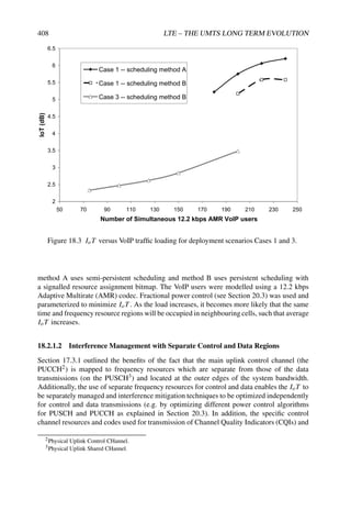
![UPLINK CAPACITY AND COVERAGE 409
ACK/NACK4 are designed to be assigned in such a manner as to reduce inter-cell and intra-
cell control channel interference under light to moderately loaded conditions, as explained in
Section 17.3.
18.2.1.3 Uplink Power Control and Interference Management
Uplink power control plays an important role in optimizing uplink system capacity. Each
UE uses path-loss measurements based on the serving cell’s Reference Symbols (RSs) to
determine the transmission power needed to compensate for a fraction of the path-loss; such
‘fractional’ power control can be parameterized by the eNodeB to effect a tradeoff between
overall spectral efficiency and cell edge performance,in conjunction with explicit closed-loop
power control commands. These mechanisms are explained in detail in Section 20.3.
Power control can be combined with frequency-domain resource allocation strategies
which allow interference coordination to further enhance cell edge performance and allow
higher overall spectral efficiency. Uplink resource allocation techniques for interference coor-
dination/avoidance are implementation-dependent and are not specified in LTE. One possible
interference coordination technique for the uplink is to schedule UEs with comparable path-
loss in adjacent cells to transmit in the same time-frequency resources [2]. On average,
such a grouping of UEs with similar channel quality in adjacent cells results in the best
cell edge performance, since it avoids strong interference from UEs close to the eNodeB in
adjacent cells (especially if the front-to-back ratio of the eNodeBs antennas is low, resulting
in significant interference between the cells).
Conversely, aligning UEs with different channel quality between cells will benefit the
UEs with good channel quality, and hence improve peak data rates and average cell
throughput.
Residual uplink interference after such interference coordination techniques may be
mitigated by receiver techniques at the eNodeB, for example employing multiple receive
antennas for beamforming, or using an Interference Rejection Combining (IRC) receiver [3]
as discussed in Section 23.3.1.2.
18.2.1.4 Uplink Control Channel Overhead
In any wireless system there is a spectral efficiency trade-off between the fraction of
transmission resources available for data and the fraction used for control signalling. The
amount of transmission resources needed for control signalling depends on the error rate
requirements (typically at or below 1% for control signalling), the size of the data packets
(small packets generally result in a higher percentage overhead from signalling), and the time
considered acceptable to switch from idle to active states. Data transmissions can make use
of whatever transmission resources are left over after resources have been allocated for the
control signalling. Hence minimizing control signalling is key to maximizing data spectral
efficiency.
4ACKnowledgement/Negative ACKnowledgement.](https://image.slidesharecdn.com/ltefromtheorytopractise-240124145854-b0067765/85/LTE_from_Theory_to_Practise-pdf-431-320.jpg)

![UPLINK CAPACITY AND COVERAGE 411
0.001
0.010
0.100
1.000
10.000
100.000
1000.000
-150 -140 -130 -120 -110 -100 -90
Transmission gain (dB)
Rate
(Mbps),
#TX
required
for
1%
BLER
.
Data rate from Shannon bound,
64QAM highest modulation
Data rate from Shannon bound,
16QAM highest modulation
Packet call throughput,
from 5 MHz LTE system sim.
#TX for 1% BLER, 576 kbps,
6 RBs, QPSK
#TX for 1% BLER, 1.92 Mbps,
20 RBs, QPSK
#TX for 1% BLER, ~ 16 kbps,
1 RB, QPSK, 4 TTI bundling,
12.2 kbps AMR VoIP,
(320 bits / 20 ms)
QPSK
16QAM
6 RB allocation 20 RB allocation
9.6Mbps
14.3Mbps
VoIP 12.2 kbps AMR
(5 Tx of 4 TTI bundle)
5
-142
Figure 18.4 Maximum rate derived from Shannon bound conditioned on whether 16QAM or
64QAM is the highest-order modulation allowed. The total number of HARQ transmissions
required to achieve 1% BLER for a given transmission gain is also shown. An Error Vector
Magnitude (EVM) of 6.3% was assumed for the transmitted signal.
18.2.1.8 Minimum Size of Resource Allocation
In high Signal-to-Interference plus Noise Ratio (SINR) conditions, the maximum achievable
capacity can be limited by the minimum amount of transmission resource which can be
allocated to a single UE. This is defined by the TTI length in the time domain and the number
of subcarriers per Resource Block (RB) in the frequency domain.
Figure 18.5 shows an example of the nominal VoIP capacity for a 1.25 MHz bandwidth
for 0.5 ms and 1 ms TTI lengths, for a range of deployment scenarios with different SINR
levels (see [4] for more details on the deployment scenarios considered). For the high SINR
scenarios, it can clearly be seen that the supportable number of VoIP users in the cell reaches a
plateau in the case of a 1 ms TTI, as the minimum resource allocation is larger than necessary
to transmit a single VoIP packet when the SINR is very high.7 This is the opposite effect
of the benefits of ‘TTI bundling’ which we observed earlier, whereby a long TTI has the
potential to increase the received energy per packet, and therefore to improve coverage at
the cell edge when the UE is power-limited. The choice of a 1 ms TTI length in LTE is
7Note that this evaluation used an RB size of 15 subcarriers in the frequency domain, which gives a slightly
larger minimum resource allocation size than is provided by the 12-subcarrier RBs in LTE.](https://image.slidesharecdn.com/ltefromtheorytopractise-240124145854-b0067765/85/LTE_from_Theory_to_Practise-pdf-433-320.jpg)
![412 LTE – THE UMTS LONG TERM EVOLUTION
80
100
120
140
160
180
200
220
240
0 1 2 3 4 5 6 7 8
NominalVoIPCapacityfor1.25MHz
0.5msTTI
1msTTI
DifferentScenarioswithIncreasingAverageSINR
Figure 18.5 Impact of RB granularity on capacity [4]. Reproduced by permission of © 2006
Motorola.
therefore a compromise between high capacity in high-SINR conditions and good coverage
at the cell edge.
In the frequency domain, the choice of a small RB size (only 12 subcarriers) helps to
ensure that the minimum resource allocation size does not unduly limit capacity.
18.2.1.9 Transmitter and Receiver Impairments
Practical impairments in the transmitter and receiver are another important constraint in a real
system. Here we introduce a method for modelling such impairments for the LTE uplink.
In the absence of receiver impairments such as non-ideal channel estimation, the DFT-
S-OFDM symbol SINR, γmmse, based on an Minimum Mean-Squared Error (MMSE)
Frequency Domain Equalizer (FDE) (see for example [5,6]) is given by
γmmse =
|G|2
Msc|G| − |G|2
(18.2)](https://image.slidesharecdn.com/ltefromtheorytopractise-240124145854-b0067765/85/LTE_from_Theory_to_Practise-pdf-434-320.jpg)
![UPLINK CAPACITY AND COVERAGE 413
where G =
Msc−1
k=0 wk|Hk|2, wk = (Hk + γo)−1 is the FDE tap for symbol k, and γo =
P/σ2
n with P being the transmit power, σ2
n the noise variance, Msc the number of subcarriers
and Hk the DFT of the channel response.
The variable γmmse in Equation (18.2) can also be written as
γmmse =
1
Msc/γsum − 1
(18.3)
where
γsum =
Msc−1
k=0
γ ideal
k /(γ ideal
k + 1)
and γ ideal
k = γo|Hk|2. Hk is the DFT of the channel response and wk is the FDE tap for
symbol k.
The Error Vector Magnitude (EVM, see Section 22.3.1.1) introduces a limitation in
effective SINR which cannot exceed γmax. More precisely the EVM-limited effective SINR
γ lim
k is given by
1
γ lim
k
=
1
γ ideal
k
+
1
γmax
(18.4)
The symbol SINR accounting for non-ideal channel estimation and the SINR limit are then
computed by
1
γ chan
k
=
1
γ lim
k
+
1
γ
pilot
k
+
1
γ lim
k γ
pilot
k
(18.5)
where γ
pilot
k = γ ideal
k /b, and b is the mean noise gain of the channel estimation filter [8].
Substituting γ chan
k from Equation (18.5) into (18.3) results in a more realistic MMSE SINR,
γmmse,n, for an uplink DFT-S-OFDM symbol.
The effect on the Block Error Rate (BLER) of the link can then be predicted by applying a
technique such as Exponential Effective SINR Mapping (EESM) to the Msymb symbol SINRs
of a packet (see Equation (18.6)) and then determining the corresponding BLER from AWGN
reference performance curves for the resulting effective SINR, i.e. SINReff, given by
SINReff = −β ln
1
Msymb
Msymb−1
n=0
exp
−
γmmse,n
β
(18.6)
where β is a parameter that must be optimized from link-level simulation results for every
combination of modulation and coding rate.
18.2.2 LTE Uplink Capacity Evaluation
In this section a number of evaluations of the LTE uplink capacity are shown for different
scenarios.
Tables 18.2 and 18.3 show spectral efficiency and cell-edge user throughput for deploy-
ment scenarios Case 1 and Case 3 (see Section 18.1) respectively, based on best-effort full
buffer traffic. The tables also show the increase in performance relative to the ‘Release-6’
UMTS uplink (HSUPA). This improvement is attributable to the uplink capacity drivers
summarized in Table 18.1.](https://image.slidesharecdn.com/ltefromtheorytopractise-240124145854-b0067765/85/LTE_from_Theory_to_Practise-pdf-435-320.jpg)
![414 LTE – THE UMTS LONG TERM EVOLUTION
Table 18.2 Summary of LTE performance evaluation results for Case 1 [7].
Spectrum efficiency Cell-edge user throughput
Tx-Rx configuration bps/Hz/cell ×HSUPA bps/Hz/user ×HSUPA Avg. IoT (dB)
HSUPA baseline 0.332 ×1.0 0.009 ×1.0 5.1
LTE 1×2 0.735 ×2.2 0.024 ×2.5 5.2
LTE 1×2 MU-MIMO 0.675 ×2.0 0.023 ×2.4 5.2
LTE 1×4 1.103 ×3.3 0.052 ×5.5 5.1
LTE 2×2 SU-MIMO 0.776 ×2.3 0.010 ×1.1 5.5
Table 18.3 Summary of LTE performance evaluation results for Case 3 [7].
Spectrum efficiency Cell-edge user throughput
Tx-Rx configuration bps/Hz/cell ×HSUPA bps/Hz/user ×HSUPA Avg. IoT (dB)
HSUPA baseline 0.316 ×1.0 0.0023 ×1.0 5.1
LTE 1 × 2 0.681 ×2.2 0.0044 ×2.0 4.5
LTE 1 × 2 MU-MIMO 0.622 ×2.0 0.0023 ×1.0 5.0
LTE 1 × 4 1.38 ×3.3 0.0094 ×4.2 2.7
Table 18.4 Time to upload 10 MB for different radio access technologies, based on system
simulations.
Normalized Maximum Avg. user 10 MB
bandwidth throughput throughputa upload timeb
Network (MHz) (Mbps) (kbps) (s)
UMTS (Rel-99) 5.0 0.384 32–90 ∼890
CDMA2000 EV-DO Rev B 5.0 5.4 50–200 ∼385
HSUPA (Rel-6) 5.0 5.74 60–200 ∼385
WiMAX 5.0 (TDD) 1.7 48–135 ∼590
LTE 5.0 10.0 147–460 ∼174
a25 to 8 FTP users/sector. b8 FTP users/sector.
Table 18.4 gives a comparison of LTE against some other radio access technologies, in
terms of the time needed to upload 10 MB of data via an FTP connection, given eight
FTP users in each cell with a 5 MHz carrier. LTE shows the lowest delay of the systems
considered.
The VoIP capacity is typically quoted in terms of a number of users per cell, as shown in
Table 18.5. VoIP services on the LTE uplink benefit from HARQ, which compensates for the
lack of uplink soft handover in LTE (i.e. no macro-diversity from reception at multiple cell
sites). For coverage-limited UEs, the use of narrow resource allocations in the frequency
domain (only 180 kHz bandwidth, corresponding to a single 12 subcarrier RB) helps to
improve coverage by increasing the power per subcarrier.](https://image.slidesharecdn.com/ltefromtheorytopractise-240124145854-b0067765/85/LTE_from_Theory_to_Practise-pdf-436-320.jpg)
![UPLINK CAPACITY AND COVERAGE 415
Table 18.5 Summary of uplink VoIP capacity [9]. Reproduced by permission of © 2007
Motorola.
Average uplink VoIP capacity
Deployment scenario (UEs/cell)
Case 1 241
Case 3 123
18.3 LTE Uplink Coverage and Link Budget
Effective operation of a cellular communication system like LTE requires not only good
cell-edge performance, but also that the different channels are well balanced in terms of the
coverage they each provide.
Figure 18.6 shows the coverage provided by the CQI and ACK/NACK information
transported on the PUCCH, compared to the Physical Random Access Channel (PRACH),8
and a 12.2 kbps AMR VoIP service transported on the PUSCH. The maximum supportable
PUSCH cell-edge data rate and maximum data rate for a 5 MHz bandwidth FDD LTE carrier
are also shown. More details on the link budget are given in Table 18.8. Table 18.6 provides
0 200 400 600 800 1000
PUSCH – VoIP (4TTI)
PUSCH – 5 kbps
PUSCH – 9.2 Mbps
CQI–10 bits (1% FER)
CQI – 4 bits (1% FER)
PRACH (Format2)
A/N (1% P(FA))
Distance (metres)
1-bit, PUCCH
5Tx,1RB,12.2kbps AMR
PUCCH
PUCCH
Case 3
Cell radius
Figure 18.6 LTE UL channel coverage for Case 3 (5 MHz FDD).
8PRACH using format 2 in this example – see Section 19.4.2.2.](https://image.slidesharecdn.com/ltefromtheorytopractise-240124145854-b0067765/85/LTE_from_Theory_to_Practise-pdf-437-320.jpg)
![416 LTE – THE UMTS LONG TERM EVOLUTION
references for the SINR targets used in the uplink link budget and Table 18.7 provides the
detection and false detection requirements for the uplink control channels. For comparison,
Tables 18.9 and 18.10 provide similar information for the downlink link budget given in
Table 18.11.
Table 18.6 Required UL Es/N0 for target error rate, 5 MHz LTE carrier.
Uplink control channel Required Es/N0 for Target ER Reference
ACK/NACK – PUCCH Es/N0 = −7.5 dB [15–18]
P(NACK → ACK) = 10−4
P(ACK → NACK) = 10−2
P(DTX → ACK) = 10−2
CQI – PUCCH Es/N0 = −7.5 dB (5-bit) for 1% BLER [17,19,20]
Es/N0 = −4.5 dB (10-bit) for 1% BLER
PRACH Es/N0 = −13.5 dB for 1% PER [10,15,17]
Table 18.7 BER targets for UL ACK/NACK signalling for LTE.
Event Target quality
ACK missed detection 10−2
DTX to ACK error 10−2
NACK to ACK error 10−4
CQI block error rate Likely to be around 10−2–10−1
The link budget results are for deployment scenario Case 3, and assume a log-normal
shadowing margin of 12.1 dB corresponding to 98-percentile single-cell area coverage
reliability and a propagation model given by
Propagation loss = 128.1 + 37.6 log(distance) (18.7)
with distance given in metres. Given the other uplink link budget assumptions from
Table 18.8, then only an average throughput of 5 kbps can be supported based on a single
(1 ms) RB PUSCH transmission as shown in Figure 18.6. The downlink SINR at 1000 m
given the corresponding downlink conditions is about −8.3 dB, which is also the SINR
required for a 1% BLER on the Physical Broadcast CHannel (PBCH) SINR [10] as shown
in Figure 18.7 and the link budget in Table 18.11. At 1000 m the transmission loss (i.e. the
propagation loss minus the antenna gains plus the log-normal shadowing margin plus the
penetration/body loss) is 146.2 dB, which must be supported by the uplink and downlink
control channels in order to achieve the 98-percentile area coverage reliability.
Under these assumptions coverage gaps can be discussed:](https://image.slidesharecdn.com/ltefromtheorytopractise-240124145854-b0067765/85/LTE_from_Theory_to_Practise-pdf-438-320.jpg)
![UPLINK CAPACITY AND COVERAGE 417
Table 18.8 LTE uplink link budget for deployment scenario Case 3 for eNodeB with 2 receive
antennas. Antenna gain + cable loss = 14 dB, penetration + body loss = 20 dB, interference
margin = 3 dB, log-normal shadowing margin = 12.1 dB (98% area coverage reliability for
propagation model given by Equation (18.7)); here VoIP uses 4 TTI bundling.
Per subcarrier
Uplink channel N. N. Tx Tx
type retx RBs Mod. Dist. Pwr Loss Rx Pwr (Io + N0)W SINR
Unit metres dBm dB dBm dBm dB
VoIP, 12.2 kbps 4 1 2 829 24.0 143.1 −122.9 −124.2 1.3
VoIP, 12.2 kbps 2 1 2 724 24.0 140.9 −122.9 −124.2 1.3
PUSCH, 5 kbps 0 1 2 1000 24.0 146.2 −133.0 −124.2 −8.8
PUSCH, 9 Mbps 0 20 4 101 24.0 108.8 −108.6 −124.2 15.6
CQI, 10-bits (1% FER) 0 1 2 770 24.0 141.9 −128.7 −124.2 −4.5
CQI, 4-bits (1% FER) 0 1 2 922 24.0 144.9 −131.7 −124.2 −7.5
PRACH, Format 2 0 6 2 830 24.0 143.2 −137.7 −124.2 −13.5
A/N 1 bit (1% P(FA)) 0 1 1 925 24.0 144.9 −131.7 −124.2 −7.5
Table 18.9 Required DL Es/N0 for target error rate, 5 MHz LTE carrier.
Downlink control channel Required Es/N0 for target ER Reference
PCFICH Es/N0 = −2.0 dB for 0.1% BER [11]
PBCH Es/N0 = −7.3 dB for 1% BLER (48-bit payload) [10]
PHICH, SF = 4 Es/N0 = −2.8 dB for 0.1% BER [12]
PDCCH, 8 CCEs
Es/N0 = −4.0 dB (48-bit) for 1% BLER [13]
Es/N0 = −5.3 dB (36-bit) [14]
Es/N0 = −6.8 dB (24-bit)
PCH Message Es/N0 = −8.3 dB for 1% BLER Same as PDSCH
Table 18.10 BER targets for downlink ACK/NACK signalling for LTE.
Event Target quality
DL scheduling info. missed detection 10−2
UL scheduling grant missed detection 10−2
NACK to ACK error 10−4
ACK to NACK error 10−4
• 1-bit ACK/NACK and 4-bit CQI Coverage via PUCCH. The 1-bit ACK/NACK and
the 4-bit CQI, shown in Figure 18.6, each transported on a PUCCH, achieve almost the
same coverage as the PBCH as shown in Figure 18.7, but fall short by approximately
1.3 dB as determined by the difference in transmission loss (146.2–144.9 dB) given in
the uplink link budget in Table 18.8. A repetition factor of 2 may be used to close the
coverage gap.](https://image.slidesharecdn.com/ltefromtheorytopractise-240124145854-b0067765/85/LTE_from_Theory_to_Practise-pdf-439-320.jpg)

![UPLINK CAPACITY AND COVERAGE 419
• 12.2 kbps AMR VoIP Coverage via PUSCH. Figure 18.6 shows that even TTI
bundling over four subframes (i.e. allocating four HARQ processes so that each VoIP
packet can occupy four consecutive TTIs) combined with five HARQ transmissions
per packet is not enough to close the coverage gap for a VoIP 12.2 kbps AMR service.
Some relaxation in error rate or reduction of the AMR codec rate (e.g. 7.95 kbps) may
be enough to close the coverage gap.
• PRACH coverage. A repeated RACH preamble burst (2 × 800 µs) is needed for the
PRACH to achieve 98-percentile or better area coverage reliability, since PRACH
format 2 (see Section 19.4.2.2), as shown in Figure 18.7, only supports a cell radius of
about 0.8 km which is close to the range supported by one Zadoff–Chu root sequence
(0.78 km). With a single sequence a total received preamble energy per sequence of
approximately 18 dB (Es/N0 ∼ −11.5 dB) is required to meet missed detection and
false alarm probabilities of less than 1% [21]. PRACH format 2 with repetition is
slightly better with a required Es/N0 = −13.5 dB for the same error probabilities.
18.4 Summary
This chapter highlights the main factors affecting uplink capacity and coverage for the SC-
FDMA-based LTE uplink. It is possible to observe how uplink coverage issues have led
to particular design choices in LTE, such as the size of a resource block, the length of the
scheduling interval (TTI), and the design of the control channels.
Evaluations can be carried out to examine the effect of each relevant factor, leading to
the LTE performance being able to be characterized by a variety of metrics. Such metrics
include average throughput, cell-edge throughput, number of VoIP users, and FTP download
time. This enables LTE to be compared against other radio access technologies.
Depending on the requirements of particular deployments, the eNodeB has the freedom to
balance average throughput against cell-edge coverage and fairness.
References9
[1] 3GPP Technical Report 25.814, ‘Physical Layer Aspects for Evolved UTRA, (Release 7)’,
www.3gpp.org.
[2] W. Xiao, R. Ratasuk, A. Ghosh, R. Love, S. Yakun and R. Nory, ‘Uplink Power Control,
Interference Coordination and Resource Allocation for 3GPP E-UTRA’ in Proc. IEEE Vehicular
Technology Conference, September 2006.
[3] J. Winters, ‘Optimum Combining in Digital Mobile Radio with Cochannel Interference’. IEEE
Journal on Selected Areas in Communications, Vol. 2, July 1984.
[4] Motorola, ‘R1-062058: E-UTRA TTI Size and Number of TTIs’, www.3gpp.org, 3GPP TSG
RAN WG1, meeting 46, Tallinn, Estonia, August 2006.
[5] Motorola, ‘R1-050719: Simulation Methodology for E-UTRA UL: IFDMA and DFT-SOFDM’,
www.3gpp.org, 3GPP TSG RAN WG1, meeting 42, London, UK, August 2005.
[6] Samsung, ‘R1-051352: Simulation Methodology for E-UTRA UL: IFDMA and DFT-SOFDM’,
www.3gpp.org, 3GPP TSG RAN WG1, meeting 43, Seoul, Korea, November 2005.
9All web sites confirmed 18th December 2008.](https://image.slidesharecdn.com/ltefromtheorytopractise-240124145854-b0067765/85/LTE_from_Theory_to_Practise-pdf-441-320.jpg)
![420 LTE – THE UMTS LONG TERM EVOLUTION
[7] Nokia, ‘R1-072261: Summary of UL LTE Performance Evaluation’, www.3gpp.org, 3GPP TSG
RAN WG1, meeting 49, Kobe, Japan, May 2007.
[8] Motorola, ’R1-061551: LTE Uplink System Performance of VoIP’, www.3gpp.org, 3GPP TSG
RAN WG1, meeting 45, Shanghai, China, May 2006.
[9] Motorola, ‘R1-072188: Performance Evaluation Checkpoint: VoIP Summary’, www.3gpp.org,
3GPP TSG RAN WG1, meeting 49, Kobe, Japan, May 2007.
[10] Motorola, ‘R1-072665: PBCH Design’, www.3gpp.org, 3GPP TSG RAN WG1, meeting 49bis,
Orlando FL, USA, June 2007.
[11] Motorola, ‘R1-072692: Coding and Transmission of Control Channel Format Indicator’,
www.3gpp.org, 3GPP TSG RAN WG1, meeting 49bis, Orlando FL, USA, June 2007.
[12] Motorola, ‘R1-072689: Downlink Acknowledgement Mapping to RE’s’, www.3gpp.org, 3GPP
TSG RAN WG1, meeting 49bis, Orlando FL, USA, June 2007.
[13] Motorola, ‘R1-072690: Support of Precoding for E-UTRA DL L1/L2 Control Channel’,
www.3gpp.org, 3GPP TSG RAN WG1, meeting 49bis, Orlando FL, USA, June 2007.
[14] Motorola, ‘R1-073374: PDCCH Channel Estimation Impact (1 versus 2 DRS) on System
Performance’, www.3gpp.org, 3GPP TSG RAN WG1, meeting 50, Athens, Greece, August 2007.
[15] Ericsson, ‘R1-081529: On Ack/Nack Repetition’, www.3gpp.org, 3GPP TSG RAN WG1,
meeting 52bis, Shenzhen, China, August 2008.
[16] Motorola, ‘R1-073371: E-UTRA Coverage’, www.3gpp.org, 3GPP TSG RAN WG1, meeting 50,
Athens, Greece, August 2007.
[17] Nokia, ‘R1-081461: Coverage Comparison between PUSCH, PUCCH, and RACH’,
www.3gpp.org, 3GPP TSG RAN WG1, meeting 52bis, Shenzhen, China, April 2008.
[18] Motorola, ‘R1-081291: Repetition of UL ACK/NACK on PUCCH’, www.3gpp.org, 3GPP TSG
RAN WG1, meeting 52bis, Shenzhen, China, April 2008.
[19] Motorola, ‘R1-073385: CQI Coding Schemes’, www.3gpp.org, 3GPP TSG RAN WG1, meeting
50, Athens, Greece, August 2007.
[20] Motorola, ‘R1-072705: Uplink CQI Channel Structure’, www.3gpp.org, 3GPP TSG RAN WG1,
meeting 49bis, Orlando FL, USA, June 2007.
[21] Panasonic and NTT DoCoMo, ‘R1-062175: Random Access Burst Design for E-UTRA’,
www.3gpp.org, 3GPP TSG RAN WG1, meeting 46, Tallinn, Estonia, August 2006.](https://image.slidesharecdn.com/ltefromtheorytopractise-240124145854-b0067765/85/LTE_from_Theory_to_Practise-pdf-442-320.jpg)

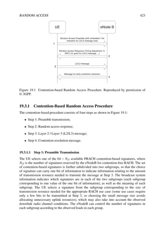
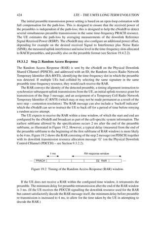


![RANDOM ACCESS 427
19.4.1 Multiplexing of PRACH with PUSCH and PUCCH
The PRACH is time- and frequency-multiplexed with PUSCH and PUCCH as illustrated
in Figure 19.5. PRACH time-frequency resources are semi-statically allocated within the
PUSCH region, and repeat periodically. The possibility of scheduling PUSCH transmissions
within PRACH slots is left to the eNodeB’s discretion.
PUCCH
PUSCH
frequency
time
PRACH
PUCCH
PRACH slot period PRACH slot period
PRACH PRACH
System
bandwidth
PRACH slot
duration
Figure 19.5 PRACH multiplexing with PUSCH and PUCCH.
19.4.2 The PRACH Structure
19.4.2.1 DFT-S-OFDM PRACH Preamble Symbol
Similarly to WCDMA, the LTE PRACH preamble consists of a complex sequence. However,
it differs from the WCDMA preamble in that it is also an OFDM symbol, built with a CP, thus
allowing for an efficient frequency-domain receiver at the eNodeB. As shown in Figure 19.6,
the end of the sequence is appended at the start of the preamble, thus allowing a periodic
correlation at the PRACH receiver (as opposed to a less efficient aperiodic correlation) [1].
The UE aligns the start of the random access preamble with the start of the corresponding
uplink subframe at the UE assuming a timing advance of zero (see Section 20.2), and the
preamble length is shorter than the PRACH slot in order to provide room for a Guard Time
(GT) to absorb the propagation delay. Figure 19.6 shows two preambles at the eNodeB
received with different timings depending on the propagation delay: as for a conventional
OFDM symbol, a single observation interval can be used regardless of the UE’s delay, within
which periodic correlation is possible.
As further elaborated in Section 19.4.3, the LTE PRACH preamble sequence is optimized
with respect to its periodic autocorrelation property. The dimensioning of the CP and GT is
addressed in Section 19.4.2.4.
19.4.2.2 PRACH Formats
Four Random Access (RA) preamble formats are defined for Frequency Division Duplex
(FDD) operation [2]. Each format is defined by the durations of the sequence and its CP, as
listed in Table 19.1.](https://image.slidesharecdn.com/ltefromtheorytopractise-240124145854-b0067765/85/LTE_from_Theory_to_Practise-pdf-449-320.jpg)

![RANDOM ACCESS 429
Maximum round-trip time. The lower bound for TSEQ must allow for unambiguous
round-trip time estimation for a UE located at the edge of the largest expected cell (i.e.
100 km radius), including the maximum delay spread expected in such large cells, namely
16.67 µs. Hence
TSEQ ≥
200 · 103
3 · 108
+ 16.67 · 10−6
= 683.33 µs (19.1)
Subcarrier spacing compatibility. Further constraints on TSEQ are given by the Single-
Carrier FDMA (SC-FDMA – see Chapter 15) signal generation principle (see Section 19.5),
such that the size of the DFT and IDFT, NDFT, must be an integer number:
NDFT = fsTSEQ = k, k ∈ N (19.2)
where fs is the system sampling rate (e.g. 30.72 MHz). Additionally, it is desirable to
minimize the orthogonality loss in the frequency domain between the preamble subcarriers
and the subcarriers of the surrounding uplink data transmissions. This is achieved if the
PUSCH data symbol subcarrier spacing f is an integer multiple of the PRACH subcarrier
spacing fRA:
fRA =
fs
NDFT
=
1
TSEQ
=
1
kTSYM
=
1
k
f , k ∈ N (19.3)
where TSYM = 66.67 µs is the uplink subframe symbol duration. In other words, the preamble
duration must be an integer multiple of the uplink subframe symbol duration:
TSEQ = kTSYM =
k
f
, k ∈ N (19.4)
An additional benefit of this property is the possibility to reuse the FFT/IFFT2 components
from the SC-FDMA signal processing for the scheduled data. Moreover, it should be possible
to implement the large DFT/IDFT3 blocks involved in the PRACH transmitter and receiver
(see Section 19.5) using a combination of the elementary FFT/IFFT blocks. For example,
an n · 2m DFT can be implemented with an FFT of 2m samples combined with a DFT of n
samples [3], since from Equation (19.4) it follows that
NDFT = kfsTSYM = kNFFT, k ∈ N (19.5)
where NFFT is the FFT size for a PUSCH symbol.
Coverage performance. In general a longer sequence gives better coverage, but better
coverage requires a longer CP and GT in order to absorb the corresponding round-trip
delay (Figure 19.6). The required CP and GT lengths for PRACH format 0, for example,
can therefore be estimated from the maximum round-trip delay achievable by a preamble
sequence which can fit into a 1 ms subframe.
Under a noise-limited scenario, as is typical of a low density, medium to large suburban or
rural cell, coverage performance can be estimated from a link budget calculation. Under the
assumption of the Okumura-Hata empirical model of distance-dependentpath-loss L(r) [4,5]
2Fast Fourier Transform / Inverse Fast Fourier Transform.
3Discrete Fourier Transform / Inverse Discrete Fourier Transform.](https://image.slidesharecdn.com/ltefromtheorytopractise-240124145854-b0067765/85/LTE_from_Theory_to_Practise-pdf-451-320.jpg)
![430 LTE – THE UMTS LONG TERM EVOLUTION
(where r is the cell radius in km), the PRACH signal power PRA received at the eNodeB
baseband input can be computed as follows:
PRA(r) = Pmax + Ga − L(r) − LF − PL (dB) (19.6)
where the parameters are listed in Table 19.2 (mainly from [6]).
The required PRACH preamble sequence duration TSEQ is then derived from the required
preamble sequence energy to thermal noise ratio Ep/N0 to meet a target missed detection
and false alarm probability, as follows:
TSEQ =
N0Nf
PRA(r)
Ep
N0
(19.7)
where N0 is the thermal noise power density (in mW/Hz) and Nf is the receiver noise figure
(in linear scale).
Assuming that Ep/N0 = 18 dB is required to meet missed detection and false alarm
probabilities of 10−2 and 10−3 respectively (see Section 19.4.3.3), Figure 19.7 plots the
coverage performance of the PRACH sequence as a function of the sequence length TSEQ.
It can be observed from Figure 19.7 that the potential coverage performance of a 1 ms
PRACH preamble is in the region of 14 km. As a consequence, the required CP and GT
lengths are approximately (2 · 14000)/(3 · 108) = 93.3 µs, so that the upper bound for TSEQ
is given by
TSEQ ≤ 1000 − 2 · 93.33 = 813 µs (19.8)
Therefore, the longest sequence simultaneously satisfying Equations (19.1), (19.4) and
(19.8) is TSEQ = 800 µs, as used for preamble formats 0 and 1. The resulting PRACH sub-
carrier spacing is fRA = 1/TSEQ = 1.25 kHz.
The 1600 µs preamble sequence of formats 2 and 3 is implemented by repeating the
baseline 800 µs preamble sequence. These formats can provide up to 3 dB link budget
improvement, which is useful in large cells and/or to balance PUSCH/PUCCH and PRACH
coverage at low data rates.
Table 19.2 Link budget parameters for analysis of PRACH preamble coverage.
Parameter Value
Carrier frequency (f ) 2000 MHz
Antenna height (hb) 30 m / 60 m
UE antenna height (hm) 1.5 m
UE transmitter EIRPa (Pmax) 24 dBm (250 mW)
eNodeB Receiver Antenna Gain (including cable loss) (Ga) 14 dBi
Receiver noise figure (Nf ) 5.0 dB
Thermal noise density (N0) −174 dBm/Hz
Percentage of the area covered by buildings (α) 10%
Required Ep/N0 (eNodeB with 2 Rx antenna diversity) 18 dB (six-path Typical Urban
channel model)
Penetration loss (PL) 0 dB
Log-normal fade margin (LF) 0 dB
aEquivalent Isotropic Radiated Power.](https://image.slidesharecdn.com/ltefromtheorytopractise-240124145854-b0067765/85/LTE_from_Theory_to_Practise-pdf-452-320.jpg)