This document is a master's thesis submitted by Amaury Van Bemten to the University of Liège in partial fulfillment of the requirements for a Master of Science degree in Computer Science and Engineering. The thesis explores using service discovery to apply policies in networks. It aims to enable sharing of resources across multiple subnets and define global access control rules. The thesis is divided into two parts - extending service discovery across routers, and implementing a graphical user interface for administrators to define security policies in the network.


![2T H E Z E R O C O N F T E C H N O L O G Y
This chapter describing the Bonjour protocol is based on [RFC3927],
[RFC4862], [RFC6760], [RFC6762], [RFC6763], the talk [Che05] of Stu-
art Cheshire, co-author of the four former RFCs, at Google TechTalks,
and on the Zeroconf guide co-authored by Stuart Cheshire and Daniel
Steinberg [CS06]. The reader can refer to those documents to find fur-
ther information.
To reach its desired plug-and-play feature, Zeroconf is made up of
three parts.
◦ An addressing mechanism to allow a device to easily and auto-
matically get an IP address. Indeed, communicating over an IP
network requires an address. This is provided by the dynamic
IPv4 link-local addresses configuration mechanism and its ver-
sion six counterpart embedded in the IPv6 protocol, both de-
scribed in Section 2.1.
◦ A naming mechanism to allow human beings not to deal directly
with the obtained IPv4 addresses or, even worse, IPv6 addresses.
On the public Internet, this is provided by the Domain Name
System (DNS), roughly described in Section 2.2. Multicast DNS
(mDNS), described in Section 2.3, achieves a similar result on
the local link with no need for a DNS infrastructure.
◦ A browsing mechanism to display a list of available services, so
that there is no need to remember names and type them. DNS-
Based Service Discovery (DNS-SD), described in Section 2.4,
provides such a mechanism.
Note that an important facet of the Zeroconf technology is
that it allows to browse for services, not hardware. For example,
a PDF reader which wants to print a file via the Internet Printing
Protocol (IPP) does not want to discover printers. Indeed, print-
ers that do not implement the IPP protocol are useless for it. The
PDF reader rather wants to discover any application making
IPP printing available to it, would it be a printer or a computer
which relays the job to a classical USB-connected printer.
Let us see how these mechanisms achieve their individual goals,
which together provide zero configuration networking.
5](https://image.slidesharecdn.com/f38b3b0e-26b5-4b32-b4ae-c5c28b84993f-160124073825/85/thesis-17-320.jpg)
![6 the zeroconf technology
2.1 link-local addressing
To do any IP networking, a device needs an IP address. Today,
this is usually done using the Dynamic Host Configuration Protocol
(DHCP) or, less commonly, manually. DHCP allows a host to get host-
specific configuration parameters (particularly an IP address) from a
DHCP server [RFC2131]. Obviously, for this to work, a DHCP server
must be accessible. This is not necessarily the case in a local network.
Link-local addressing provides a safety net when DHCP is failing or
unavailable, allowing the host to still get an IP address. The obtained
address will only be valid for communications on the local link.
[RFC3927] describes the process for IPv4 addresses configuration.
The address obtained by such a process will be part of the 169.254/16
subset which is defined only on the local link. This means that the
address will have no significance outside the local subnet (beyond
any router).
A host willing to get an address simply selects one randomly in the
defined subset. The host then broadcasts an ARP1 request for the cho-
sen address. If the host does not receive any ARP reply nor sees any
conflicting ARP request, it has successfully claimed the desired IPv4
address and has now to announce it via ARP announcements in order
to update possible old stale ARP cache entries. In case of conflict, the
host simply chooses another address and restarts the process. Note
however that, as computed in [RFC3927], conflicts should be rare: “A
host connecting to a link that already has 1300 hosts, selecting an IPv4 Link-
Local address at random, has a 98% chance of selecting an unused IPv4
Link-Local address on the first try.”
IPv6 provides a similar functionality [RFC4862]. IPv6 hosts form
link-local addresses by appending an interface identifier to the well-
known fe80:: link-local prefix. The host then verifies that the built
address is not yet used by multicasting an NDP2 neighbor solicitation
message. This kind of message is used to verify that a neighbor is
(still) reachable [RFC4861]. If someone answers, the host has to use
another (if any) interface identifier and restart the process. Otherwise,
the IPv6 link-local address is successfully claimed.
1 The Address Resolution Protocol (ARP) provides a mechanism to translate an IP
address to the MAC address of the host using it on the local link.
2 The Neighbor Discovery Protocol (NDP) is specific to IPv6. Among other function-
alities, it provides a service similar to ARP for IPv4.](https://image.slidesharecdn.com/f38b3b0e-26b5-4b32-b4ae-c5c28b84993f-160124073825/85/thesis-18-320.jpg)
![2.2 domain name system 7
2.2 domain name system
Before diving into the DNS-based Zeroconf technology, let us briefly
review the vanilla DNS protocol. The reader already familiar with the
protocol may easily skip this section.
2.2.1 The Name Space
The Domain Name System (DNS) [RFC1034; RFC1035] is used to
translate a name into some data, usually an IP address. The name
space defined by DNS is a tree structure. Each node has a label,
unique among its brothers. The complete domain name of a node
is the list of the labels on the path from the node to the root of the
tree, separated by dots. The root name is the null character, which
means that a fully qualified DNS name always ends with a dot.
2.2.2 The Resource Records
A domain name thus identifies a node. Each node has a set of
data associated to it. This data is collected in a list of resource records
(RRs). A record is composed of five parts.
◦ The name of the node concerned by the record.
◦ The type of information that is stored in the record.
◦ A class. Usually, and in this work, the class is Internet. It is the
only class that is widespreadly used nowadays.
◦ A Time-To-Live (TTL) which defines how long (in seconds) the
record can be stored in a cache before having to be discarded.
◦ The data, whose structure depends on the type of the record.
A great number of record types have been defined. The most com-
monly known goal of DNS is to store IP addresses. This is done
thanks to A and AAAA records. The former maps a name to an IPv4
address while the latter maps a name to an IPv6 address.
2.2.3 Name Servers
Rather than relying on a central authority, DNS uses a database
distributed among name servers. The name space is divided into zones
which are subtrees of the global tree rooted at the . node. Name
servers are responsible, or authoritative, for a particular zone. Orga-
nizations may register a name through a registrar in order to control
it as a new zone [Int03]. Within a zone, an NS record is defined for](https://image.slidesharecdn.com/f38b3b0e-26b5-4b32-b4ae-c5c28b84993f-160124073825/85/thesis-19-320.jpg)
![8 the zeroconf technology
each subzone. This record points to the name of the name server re-
sponsible for the given subzone. Requests for particular records must
hence be addressed to a name server responsible for the zone or a
parent zone of the requested name. Indeed, the NS records will then
be used to forward the request to the authoritative server. As . is par-
ent of any registered domain name, any request can be issued to the
name servers responsible for the root domain, which are well-known.
For example, a request for an A record for laptop.vyncke.org. to the
root servers will be processed as follows.
1 - The root server will find, in its database, an NS record corre-
sponding to the org. subdomain and forward the request to the
server specified by the record.
2 - The server responsible for the org. domain will have a similar
behavior, forwarding the request to the name server responsible
for the vyncke.org. domain.
3 - The final server will then have the requested A record in its
database and will finally return it to the user.
Of course, this process relies on the correct configuration of the
name servers, which must contain NS records for each of the defined
subzones.
2.2.4 DNS Messages
Every DNS message, be it a response or a query, is divided in
five parts: a header, a question, an answer, an authority and an addi-
tional section. The header gives information on the message content,
type and purpose. The four latter sections are simply composed of
resource records. The question section carries the records that are
wanted. The answer section carries answers to the query. In a DNS
query, this can contain partial answers the querier knows so that
name servers do not waste bandwidth for information the querier
already knows. The authority section carries records which describe
other authoritative servers for the asked records. The additional sec-
tion is used to carry records that could be useful when using the
records of other sections. For example, if a section provides the name
of a server via an NS record, the additional section could carry the
AAAA record corresponding to this name.
For further information on DNS, Kurose and Ross provide a nice,
comprehensive and pedagogical introduction to the protocol in their
networking book [KR13].](https://image.slidesharecdn.com/f38b3b0e-26b5-4b32-b4ae-c5c28b84993f-160124073825/85/thesis-20-320.jpg)
![2.3 multicast dns 9
2.3 multicast dns
For the DNS to work, one must run DNS servers and assign, al-
locate and manage the globally unique names. The Multicast DNS
(mDNS) protocol [RFC6762] allows to use a DNS-like service in a
LAN without these requirements. The DNS names concerned by this
local service are those falling in the local. domain, which is reserved
for link-local name resolution. This use of a carved subtree of the DNS
namespace is similar to link-local addresses which are also valid only
on the local link. Note that mappings may be done with addresses
obtained differently than as explained in Section 2.1.
Instead of relying on a centralized authority, mDNS requires each
host to answer itself, as a conventional DNS server would have done.
Queries are sent to the IPv4 multicast address 224.0.0.251 or to the
IPv6 multicast address ff02::fb on UDP port 5353. Because those ad-
dresses are in the link-local multicast ranges of IPv4 and IPv6, mDNS
packets are never forwarded outside the local link. The payload of
these packets are classical DNS queries. Each device listens and, when
it sees a query for its name or other mDNS data it knows, it answers
with a standard DNS response.
When a host wants to announce a unique3 record on the LAN, it
must first send three queries (called probes) for this record in order to
ensure that it does not already exist. If a response is received, the host
cannot use the given record and should choose a new name before try-
ing again. If no response is received, the host must then announce its
newly obtained record thanks to a gratuitous mDNS response with
the new record in the answer section. The TTL field of the mDNS
packets is used by the hosts to determine when a record must be dis-
carded. Note that if a host knows some of its data is becoming invalid
(e.g., during a proper shutdown) it multicasts a goodbye packet, which
is a packet with a TTL field of 0. This will result in the other hosts
removing the entry from their cache.
A continuous query of the network to display a live list of records
would impose an unreasonable burden on the network. Therefore,
mDNS uses very aggressive techniques to limit the traffic:
◦ Known answer suppression. The querier includes a list of known
answers in the answer section of the mDNS query. This allows
to avoid wasting network capacity with useless repeated trans-
mission of those answers.
3 We distinguish unique records from shared records. With shared records, different
responders may own records with the same name, type and class. Those do not
require to perform the described probing process.](https://image.slidesharecdn.com/f38b3b0e-26b5-4b32-b4ae-c5c28b84993f-160124073825/85/thesis-21-320.jpg)
![10 the zeroconf technology
◦ Exponential backoff for queries. A querier must, at least, dou-
ble the time interval between two successive queries, the initial
interval being of at least one second. Once the querier reaches
one query per hour, it may continue at this constant polling
rate. Note that this does not mean that it could require one hour
to discover a record. Indeed, the announcement procedure de-
scribed above allows devices observing the network to discover
new records without having to issue any query.
◦ Caching using the TTL field.
◦ Responses are, most of the time, also sent via multicast. Thanks
to this, each device on the LAN witnesses all the mDNS ex-
changes and can update its cache accordingly, without issuing
any request.
mDNS requires the devices on the network to collaborate. Conse-
quently, mDNS is not a good solution in a hostile environment.
2.4 dns-based service discovery
With the current link-local addressing and mDNS mechanisms,
one can do useful networking quite easily. However, Zeroconf does
not stop there. So far, we still need to know, remember and type host-
names correctly. We would like a list to appear so that we only have
to click on a name to communicate with it. That is the purpose of
Zeroconf’s DNS-Based Service Discovery (DNS-SD) protocol.
DNS-SD is simply a way of using DNS records to facilitate service
discovery. It is accomplished by building on the standard DNS, not
by defining new resource records or messages formats. The protocol
uses DNS’ PTR, SRV and TXT records to define a service. Let us see
what these are initially used for.
◦ A PTR record simply carries a pointer to another part of the
domain name space [RFC1034].
◦ An SRV record specifies the location of a service. The data as-
sociated to such a record contains an integer priority, an inte-
ger weight, a port number and a target hostname specifying on
which port and host the service runs. The fact that the port num-
ber is provided removes the limitation of having only a single
service of a given type on a machine. One can now run several
identical services on different ports of a single machine and
does not have to rely on well-known ports anymore [RFC2782].
◦ A TXT record is used to hold descriptive text. The data associ-
ated to such a record is simply a string of bytes whose significa-
tion depends on the context [RFC1035].](https://image.slidesharecdn.com/f38b3b0e-26b5-4b32-b4ae-c5c28b84993f-160124073825/85/thesis-22-320.jpg)

![3.1 extending service discovery across routers 15
on its LAN will simply encapsulate the packet in an IPv4 or IPv6
datagram which it will then transmit to the other router(s). Despite
looking simple, this scheme introduces the following complications.
◦ Routers would have to be manually configured to know to which
IP addresses they have to send their mDNS traffic. In the case of
IPv6, addresses may be valid only for hours or days [RFC4862;
RFC3041; RFC3315] before changing. Even if the router chang-
ing address could avertise the other router of its new address,
this adds a non-negligible overhead.
◦ DNS records transmitted over mDNS will most of the time point
to a link-local address. Hence, address conflicts could occur be-
tween the subnets, since the link-local address assignment is
made separately. To circumvent this problem, we can logically
merge the two subnets. In this way, no address conflict will
occur and devices from initially separate subnets will be able
to communicate with each other using their link-local address.
However, logically merging the two subnets only for service dis-
covery would induce a big overhead and a security flaw since
devices in different subnets are not supposed to communicate
with each other (except for the potential services of course). Rou-
ters could filter the packets but this becomes somewhat too cum-
bersome.
◦ Devices would not be able to distinguish a local from a remote
service as they would all appear in classical mDNS packets.
◦ So far, we have only considered two subnets communicating. In
the case of n subnets, the situation becomes even more complex.
Connecting each subnet with all the others would result in n2
communications. A master router could be designated to be on
top of all others, receiving all the traffic and forwarding it to the
appropriate subnets. However, it represents a single point-of-
failure and the solution becomes rather complicated. Therefore,
the solution is not scalable.
◦ Last but not least, such a solution requires to configure the dis-
covering router to be part of the system. This is a tight constraint
as traveling employees are not likely to be able to configure the
router of the institution they are visiting.
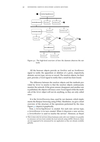
3.1.2.2 State Exchange
Rather than simply forwarding all the mDNS traffic, each router
could maintain a state of its subnet, i.e. all the resource records an-
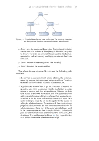
nounced on its LAN. This is in line with the concept of zone in the](https://image.slidesharecdn.com/f38b3b0e-26b5-4b32-b4ae-c5c28b84993f-160124073825/85/thesis-27-320.jpg)
![16 solution architecture
Router1
LAN1 Wireless Access Point
Computer
Laptop
Internet
Mobile Phone
PrinterHTTP Server
User
Router2
LAN2
FTP Server
mDNS
State Exchange
mDNS
Figure 3.2: Routers sharing their services by keeping a state of the mDNS
traffic on their respective local links.
DNS specification. Recall from Section 2.2 that DNS organizes the au-
thoritative information into zones for which different name servers
are responsible.
Each LAN could be represented by a zone, with the records an-
nounced on the LAN describing (partially) the zone. Since a zone
corresponds to a subset of the namespace, each subnet should be
assigned a name. To be consistent with mDNS, each subnet can be as-
signed a single-label subdomain below the local. domain. [RFC6762]
says that “any fully qualified name ending in ".local." is link-local, and
names within this domain are meaningful only on the link where they origi-
nate.” Even though our idea extends the local. domain to several sub-
nets where this quote states that the names are not valid anymore, it is
not problematic since implicated subnets are aware of this extension.
The mechanism would be the following.
1 - In Figure 3.2, let us suppose that User wants to discover IPP
printers in LAN1 which has been assigned the domain home.local..
To do so, User issues an mDNS query on the local-link for a PTR
record with the name _ipp._tcp.home.local.. The mDNS specifica-
tion [RFC6762] requests that “Any DNS query for a name ending
with ".local." MUST be sent to the mDNS IPv4 link-local multicast
address 224.0.0.251 (or its IPv6 equivalent FF02::FB).” Hence, we
are sure that the request will be sent using mDNS and not Uni-
cast DNS.
2 - As the device (FTP Server) on the LAN has no information about
this domain, it does not answer.](https://image.slidesharecdn.com/f38b3b0e-26b5-4b32-b4ae-c5c28b84993f-160124073825/85/thesis-28-320.jpg)
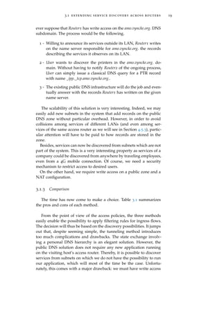
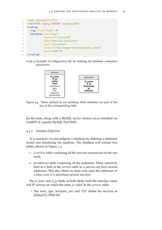
![18 solution architecture
Router1
LAN1 Wireless Access Point
Computer
Laptop
Internet
Mobile Phone
PrinterHTTP Server
User
Router2
LAN2
FTP Server
Authoritative
DNS Server
Local
DNS Server
mDNS
mDNS
DNS Update
DNS Query
DNS
Figure 3.4: Routers sharing their services via public DNS servers.
– If the domain is local., the answer will be provided by the
classical mDNS mechanism. Indeed, devices still announce
themselves on the single label local. domain.
– If the domain is <sub-d>.local., the access router will for-
ward the request to the master router which will delegate
the request to the router authoritative for the given subdo-
main, as in classical DNS. The latter will then be able to
answer the request to the access router, which will finally
forward the answer back to the initial client. This is, to
some extent, a parallel DNS hierarchy separated from the
public one.
Although this solution nicely overcomes the scalability problem of
the tunneling method, it still requires the discovering routers to be
configured as part of the system.
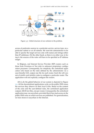
3.1.2.3 Using the Public DNS
Rather than a direct communication between the routers, it is also
possible to communicate via an intermediate. Since Zeroconf is based
on DNS, the public DNS infrastructure seems to jump out for this job.
The situation is depicted in Figure 3.4.
As DNS-SD specifies how a service can be announced using classi-
cal DNS records, sharing the services announced in the different sub-
nets using the existing public DNS infrastructure is perfectly suited
to our problem. The big drawback of such a method is that we must
have write access to the public DNS in order to insert the desired
records. Unfortunately, this access is seldom free [Int03]. Let us how-](https://image.slidesharecdn.com/f38b3b0e-26b5-4b32-b4ae-c5c28b84993f-160124073825/85/thesis-30-320.jpg)

![24 extending service discovery across routers
The application will parse and validate the XML file against its DTD
at startup in order to check that it is suitably configured.
4.2 observing the services
4.2.1 Avahi
The first job of the application is to observe the services announced
on the LAN. Although the Zeroconf protocols are simple, implement-
ing all the cache and traffic reduction mechanisms from scratch would
be far too long and cumbersome for the sake of this work. Moreover,
there exist several open-source implementations of the Bonjour pro-
tocol that run on Linux. The probably most popular of them is Avahi.
Back in 2005, Stuart Cheshire, one of the Bonjour protocol co-authors,
mentioned the high quality of Avahi [Che05]:
“Avahi is absolutely great. [...] They know the protocols inside
out, [...] we are working together with them. [...] Avahi is the
best one [Bonjour implementation] I know. [...] It really does
challenge Apple in terms of its completeness and its robustness.”
— Stuart Cheshire
In addition, Avahi is now part of major Linux distributions such
as Debian, Fedora, Mandriva, FreeBSD, openSUSE, ArchLinux and
Ubuntu [Tea10].
Avahi uses D-Bus for communication between applications and
the Avahi daemon which implements the Bonjour architecture. An
application may, using D-Bus, ask the daemon to be notified when
new services arrive, to resolve a service, to publish a service, and
many other possibilities. How Avahi behaves can be modified via a
configuration file. Section 4.2.3.1 addresses the Avahi daemon config-
uration step. Our upcoming tests have been made using the 0.6.31
version of the Avahi daemon.
As D-Bus is not necessarily a well-known technology, Section 4.2.2
provides an overview of what it is and how it works. Any program-
ming language with D-Bus support can access the Avahi daemon
[Tea02]. Among the language bindings available for D-Bus, Python
seems to be the best choice [Dbua]. Indeed, it is high-level and pro-
vides an outstanding number of libraries which will facilitate our
coding and allow us to focus on the algorithmic part of the code. The
application has been tested and coded for Python 2.7.5.](https://image.slidesharecdn.com/f38b3b0e-26b5-4b32-b4ae-c5c28b84993f-160124073825/85/thesis-36-320.jpg)
![4.2 observing the services 25
4.2.2 D-Bus
This section provides an introduction to D-Bus. It is based on a
document by the freedesktop.org project [Dbuc].
4.2.2.1 Buses, Objects and Proxies
D-Bus is developed as part of the freedesktop.org project, which
builds a base platform for open source and open discussion desk-
top software projects on Linux and UNIX [Fre]. D-Bus is an inter-
process communication (IPC) mechanism allowing processes on the
same host to communicate with each other.
D-Bus provides a logical bus between applications. It is based on
a daemon which forwards the messages. Any number of applications
may connect to this daemon to participate to the communication. The
daemon provides two kinds of buses: a system bus for system-wide
communications and session buses used by a single ongoing user
session. Each bus can be connected to thanks to an address, which is
typically the filename of a Unix-domain socket. Each connection to a
bus is assigned a bus name. This can be a unique name automatically
assigned by the bus, in which case it starts with a colon, or it can be
chosen by the application connecting to the bus in order to offer a
service under a well-known name, in which case the name consists of
two or more dot-separated elements.
In the D-Bus jargon, an object is a communication endpoint at one
end of any exchange. It is a way for a process to offer its services
on the bus. An object has a name, called a path composed of slash-
separated elements. An object is part of a connection and may be
accessed through a proxy, which is a local representation in a program
of a remote object.
4.2.2.2 Messages
There are two ways of communicating on the bus with another
process.
◦ 1:1 request-reply. Requests are sent from a client to an object and
the latter answers back to the requesting process. This is, from
the querier point of view, seen as the invocation of a method on
the object or proxy. Both asynchronous and synchronous calls
are possible.
◦ 1:n publish-subscribe. Messages emanating from an object are
broadcasted to any connected client that have registered an in-
terest in the given object. The messages sent by the object are
called signals. Like methods, signals can carry parameters. They
are generally used to publish the occurence of an event.](https://image.slidesharecdn.com/f38b3b0e-26b5-4b32-b4ae-c5c28b84993f-160124073825/85/thesis-37-320.jpg)
![4.2 observing the services 27
erence library implementing the well-behaved daemon specification
of [PEP3143]3.
Our application thus uses python-daemon version 1.5.7 to imple-
ment a daemon. The code is available in /decentralized/python/service-
discovery-daemon.py in this work’s archive. The daemon can be started,
stopped and restarted with the command
$ ./service-discovery-daemon.py cmd
where cmd is respectively start, stop or restart. Let us explore several
aspects of our daemon.
4.2.3.1 Avahi Configuration
/etc/avahi/avahi-daemon.conf is the configuration file for the Avahi
daemon [man]. Its syntax simply consists of a series of key=value lines
allowing to define the value of several parameters. We will here go
only through interesting parameters.
use-ipv4. This must be set to yes in order to allow Avahi to use IPv4
sockets. Of course, the user may disable this option if he does
not want the software to consider services announced on IPv4.
Note that “announced on IPv4” means that the service has been
announced using the IPv4 protocol. Nothing guarantees that the
IP address associated to the service is either IPv4 or IPv6.
use-ipv6. Similarly to IPv4, this option should be enabled but the
user could decide to disable it.
deny-interfaces. This parameter allows to set a list of comma sepa-
rated network interfaces that should be ignored by the Avahi
daemon, which means that the services announced on those
interfaces will not be considered. Interfaces that are not speci-
fied will be used, unless allow-interfaces is set, which takes prece-
dence over deny-interfaces. It is up to the user to determine whether
or not some interfaces should be ignored but we, by default, ig-
nore no interfaces.
allow-interfaces. Interfaces that are not specified here will be ignored
by the Avahi daemon. If set to an empty list, all local interfaces
except loopback and point-to-point will be observed. By default,
we set this parameter to an empty list.
enable-dbus. Must be set to yes in order to allow the application to
communicate with the Avahi daemon.
3 A PEP is a Python Enhancement Proposal. These documents are intended to provide
concise technical specifications of new Python features [PEP0001].](https://image.slidesharecdn.com/f38b3b0e-26b5-4b32-b4ae-c5c28b84993f-160124073825/85/thesis-39-320.jpg)
![28 extending service discovery across routers
enable-reflector. If set to yes the Avahi daemon will reflect all the
mDNS traffic to all local interfaces. This must be set to no and
will be justified in Section 4.5.3.
reflect-ipv. If set to yes the Avahi daemon will forward traffic between
IPv4 and IPv6. It can be set only if enable-reflector is enabled. This
must be set to no and will also be justified in Section 4.5.3.
Other parameters may be tweaked as wanted by the user. Note
that not mentioning these in this section does not mean they will not
influence the behavior of the application, but rather that they will
not affect the correct behavior of the daemon. A valid configuration
file is provided in /decentralized/config/avahi-daemon.conf in this work’s
archive.
4.2.3.2 D-Bus Configuration
In most of the cases, the D-Bus daemon requires no particular
configuration. However, D-Bus imposes several resource limitations
related to the connections made to the bus [Dbub]. In case of big
networks with many services announced, those limits can impede
the operations of our daemon. For example, when operating in the
University of Liège (ULg) network (B31 building), the daemon was
connecting to too many signals from D-Bus. The initial configuration
of the D-Bus daemon prevented our daemon to operate properly. To
solve this problem, we had to add a rule in the configuration file in
order to increase the maximum number of match rules allowed per
connection. The exact parameters to tweak and the values highly de-
pend on the network. Fortunately, configuration is most of the time
not required. If it is, the /decentralized/config/system-local.conf configu-
ration file we used should be most of the time sufficient4.
4.2.3.3 Logging
Our program is intended to be launched at a router startup. The
program output is then supposed to be monitored remotely, possi-
bly from different hosts, or along different ssh sessions. The standard
output and error streams are thus not convenient for such a situa-
tion. Consequently, we use a logger for information and error logging.
This object is part of the logging Python package. It allows to easily
print different types of messages in a log file rather than on the stan-
dard stdout and stderr streams. The logger can then be configured to
only print several message types and format them appropriately and
4 Note that, on Linux machines, modifying the configuration file of D-Bus must be
done with care. Indeed, some Linux desktop environments such as Gnome or KDE
use D-Bus and an invalid configuration could prevent the graphical environment
from operating properly or even from being launched. If we mention this, it might
be because we experienced such a problem...](https://image.slidesharecdn.com/f38b3b0e-26b5-4b32-b4ae-c5c28b84993f-160124073825/85/thesis-40-320.jpg)
![4.2 observing the services 29
easily [Py-Doc]. The module defines five message levels: critical, er-
ror, warning, info and debug. We will only use the latter four. Using
the configuration file, the user will be able to specify a level below
which messages are not printed (e.g., specifying info will print all
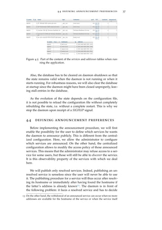
messages except debug). The DTD defining the current config.xml for-
mat is shown in Code 1 and a corresponding XML example5 in Code
2.
1 <!ELEMENT config (log)>
2 <!ELEMENT log EMPTY>
3 <!ATTLIST log level CDATA #REQUIRED>
Code 1: DTD for defining the logging verbosity level.
1 <?xml version="1.0"?>
2 <!DOCTYPE config SYSTEM "config.dtd">
3 <config>
4 <log level="info" />
5 </config>
Code 2: Example of config.xml for setting the logging verbosity level to info.
As, on Linux, the /var/log/ directory is used to store various log
files [Nem+10], the log file used by our daemon will be /var/log/service-
discovery.log. Any message from the daemon will thus be written in
this file6.
4.2.3.4 PID File
The python-daemon package allows to use a PID file created on the
daemon startup and containing the process ID (PID) of the daemon.
This file may be used to kill the daemon (as it allows to fetch the PID
and then issue a kill command) or to see if it is running or not. PID
files are usually stored in the /var/run/ directory [Nem+10]. Conse-
quently, the daemon will use /var/run/service-discovery/pid as its PID
file.
4.2.3.5 Signals Handling
The python-daemon package allows to provide callback methods
that will be called when receiving particular signals from the operat-
ing system. Defined signals depend on the operating system. Among
5 The xmllint tool can be used with the option --dtdvalid to check whether an XML file
is a valid instance of a DTD or not.
6 A simple
tail -f /var/log/service-discovery.log
command can be issued in order to monitor the instantaneous progress of the dae-
mon.](https://image.slidesharecdn.com/f38b3b0e-26b5-4b32-b4ae-c5c28b84993f-160124073825/85/thesis-41-320.jpg)
![30 extending service discovery across routers
the signals that should be supported on all Unix implementations and
that can be caught [IG04], SIGABRT, SIGINT, SIGQUIT and SIGTERM
should lead to a clean daemon shutdown procedure. We will hence
call a stop procedure upon reception of these signals, which will
cause the daemon to clear its state and then exit. Note that the python-
daemon package uses SIGTERM to stop the daemon when called with
the stop argument.
Furthermore, the SIGHUP signal is commonly interpreted by dae-
mons as a reset request, i.e. daemons usually reload their configura-
tion file when receiving a SIGHUP signal [Nem+10]. Indeed, among
others, the D-Bus daemon dbus-daemon, the OpenSSH daemon sshd
and the Avahi daemon avahi-daemon reload their configuration file
when receiving a SIGHUP signal [man]. However, our daemon is un-
able to reload its configuration file without a complete restart (See
Section 4.3.2). Hence, it will simply terminate when receiving a SIGHUP
signal, as this is the default action that should be taken [IG04]. In
order to reload the configuration file, the daemon will have to be
completely restarted thanks to the restart command.
4.2.3.6 Privileges
Until now, we did not consider permissions and access rights re-
quired by the Linux operating system to perform certain operations.
Our daemon has to interact with several files on the system:
1 - The log file in order to log events. The daemon must have write
access on this file. A GUI must have read access on this file in
order to display the logs.
2 - The configuration file in order to adapt its behavior based on
user-defined preferences. The daemon must have read access
on this file. A GUI must have write access on this file.
3 - The DTD of the configuration file in order to check that it is
valid. The daemon and the GUI must have read access on this
file.
A nice solution is to create a group (which we will name sd for
service discovery) containing two users: sd-daemon and sd-gui. The
daemon will run as sd-daemon and the GUI as sd-gui. Based on this,
appropriate permissions must be set on the desired files and direc-
tories. For this purpose, we provide the /decentralized/setup.sh script
which must be run as root. It creates the sd group and the sd-daemon
and sd-gui users and the necessary directories and files with the ap-
propriate permissions. Note that the config.xml and config.dtd files are
taken from the /decentralized/config/ directory. In addition, the script](https://image.slidesharecdn.com/f38b3b0e-26b5-4b32-b4ae-c5c28b84993f-160124073825/85/thesis-42-320.jpg)
![4.2 observing the services 31
sets the /decentralized/config/avahi-daemon.conf file as the Avahi config-
uration file and the /decentralized/config/system-local.conf file as the D-
Bus additional system-wide configuration file.
Besides, the daemon commands will now only be allowed as root
so that the daemon process can then be forked with the user ID and
group ID corresponding to sd-daemon and sd respectively, in order to
be allowed to perform the required operations, no more, no less.
4.2.3.7 Observation of the Bonjour Traffic
Among the several Python D-Bus bindings, we used dbus-python
version 1.2.0. This choice has been motivated by its simplicity of use
and the fact that it is the reference implementation of D-Bus [Dbua].
The Avahi D-Bus API is not documented. However, the D-Bus in-
trospection data7 is provided on the Avahi website [Tea08]. Despite
this poor amount of documentation, it was enough to use the API.
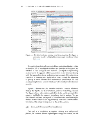
Let us see the objects made available by Avahi. In the list below, all
the names begin with org.freedesktop.Avahi. but this part has been trun-
cated for presentation reasons.
Server. It represents the Avahi daemon. Initially, this is the only ob-
ject made available by Avahi. The methods and signals it im-
plements are shown in Figure 4.1. Most importantly, it provides
methods to create each of the eight following objects.
EntryGroup. Allows to publish records and/or services.
DomainBrowser. Allows to browse for browsable domains.
ServiceTypeBrowser. Allows to browse for announced service types
on a given domain.
ServiceBrowser. Allows to browse for announced services of a given
type on a given domain.
RecordBrowser. Allows to browse for resource records of a given type,
class and name.
ServiceResolver. Allows to resolve a given service.
HostnameResolver. Allows to resolve a given hostname.
AddressResolver. Allows to resolve a given address.
We will not use EntryGroup, as we are only looking to observe the
LAN, not to publish on it. We will not use DomainBrowser either as
we are only looking to browse the local. domain.
7 This means the interfaces, methods and signals that objects implement.](https://image.slidesharecdn.com/f38b3b0e-26b5-4b32-b4ae-c5c28b84993f-160124073825/85/thesis-43-320.jpg)
![4.3 keeping the registered services in memory 33
$ tail -f /var/log/service-discovery.log &
[1] 6258
$ sudo ./service-discovery-daemon.py start
12-11-2014 13:55:15 CEST - INFO - Command start issued.
12-11-2014 13:55:15 CEST - INFO - Service discovery daemon startup.
12-11-2014 13:55:15 CEST - DEBUG - Browsing for services types.
12-11-2014 13:55:15 CEST - DEBUG - Browsing type _printer._tcp on wlp4s0 (IPv4).
12-11-2014 13:55:15 CEST - DEBUG - Browsing type _http._tcp on wlp4s0 (IPv4).
12-11-2014 13:55:15 CEST - DEBUG - + DCP-1510 @ MacBookPro_BobK._printer._tcp on (IPv4).
12-11-2014 13:55:15 CEST - DEBUG - + iPhone de Guillaume._http._tcp on wlp4s0 (IPv4).
12-11-2014 13:55:15 CEST - DEBUG - + CodeMeter WebAdmin._http._tcp on wlp4s0 (IPv4).
12-11-2014 13:55:16 CEST - DEBUG - = Resolved CodeMeter WebAdmin._http._tcp to
MacBook-Pro-de-Louis.local on wlp4s0 (IPv4).
12-11-2014 13:55:16 CEST - DEBUG - New IPv4 address (10.9.141.79) for
MacBook-Pro-de-Louis.local on wlp4s0 (IPv4).
12-11-2014 13:55:17 CEST - DEBUG - = Resolved iPhone de Guillaume._http._tcp to
iPhone-de-Guillaume.local on wlp4s0 (IPv4).
12-11-2014 13:55:17 CEST - DEBUG - New IPv4 address (10.9.139.93) for
iPhone-de-Guillaume.local on wlp4s0 (IPv4).
...
Figure 4.3: Hypothetical service-discovery-daemon.py logs.
Cheshire mentions it in its Google Talk [Che05] and in its guide
[CS06], services are to be resolved at using time9, as their hostname,
address, port or TXT could change during their lifetime. Nonethe-
less, this is not a problem since, as Section 8.4 of [RFC6762] men-
tions it, “if the rdata of any of a host’s Multicast DNS records changes, the
host MUST repeat the Announcing step [...] to update neighboring caches.”.
Consequently, in case of change, the ServiceResolver object will issue
a new Found signal. Such a method allows only for one address per
host. Indeed, the Found signal only gives one single address. This is
not practical for services that are announced over IPv4 and IPv6 and
that can hence have several addresses. Consequently, we will not con-
sider the address returned by the Found signal of the ServiceResolver
object but rather use two RecordBrowser objects to browse for IPv4 and
IPv6 addresses of the hostname returned by the Found signal. This
method allows to continuously resolve a service, thereby performing
the required late binding.
The daemon logs the observed services as debug messages. Figure
4.3 shows the obtained logs when connected to the ULg network10.
4.3 keeping the registered services in mem-
ory
The daemon is now able to monitor the Bonjour traffic. However,
in order to know the current state of the network, we need to store
9 This is called late binding, as mentioned in Section 2.4.
10 Names have been changed and output truncated for privacy and presentation rea-
sons.](https://image.slidesharecdn.com/f38b3b0e-26b5-4b32-b4ae-c5c28b84993f-160124073825/85/thesis-45-320.jpg)
![34 extending service discovery across routers
the registered services in memory. The simplest way to achieve this
is to store the services in a Python data structure. Nonetheless, this
does not allow an external GUI to access the services. This possibil-
ity can although be achieved using shared memory or by having the
Python application printing the services in a file. This communica-
tion between the daemon and the GUI is not easy to implement. A
much more easier method is to store the services in a database, which
the GUI will access to retrieve the wanted information. In addition,
as Section 4.6 will describe it more precisely, our GUI will be imple-
mented as an HTTP server, which can easily access and modify a
database.
For its popularity, rich documentation and access facilities from
Python and PHP code (used respectively for the daemon and the
GUI), MySQL has been chosen to be the database management sys-
tem used in this work. Chapter 2 of the MySQL Connector/Python
Developer Guide, part of the MySQL documentation [MySQL-Doc],
recommends not to hardcode the values needed to connect to the
database into the main script. This is a place for our config.xml file.
We therefore now add a new element database to our DTD to allow
the user to specify the connection parameters. The updated DTD is
shown in Code 3 and a corresponding configuration example in Code
4.
1 <!ELEMENT config (log,database)>
2 <!ELEMENT log EMPTY>
3 <!ATTLIST log level CDATA #REQUIRED>
4 <!ELEMENT database EMPTY>
5 <!ATTLIST database user CDATA #REQUIRED>
6 <!ATTLIST database password CDATA #REQUIRED>
7 <!ATTLIST database name CDATA #REQUIRED>
8 <!ATTLIST database host CDATA #REQUIRED>
9 <!ATTLIST database socket CDATA #REQUIRED>
10 <!ATTLIST database port CDATA #REQUIRED>
Code 3: DTD for defining the database connection parameters.
The user, password, name, host, socket and port attributes correspond
respectively to the user, password, database, host, unix_socket and port
connection arguments referenced in Chapter 7 of the MySQL Con-
nector/Python Developer Guide. Note that all attributes are set to be
mandatory. It is up to the user to insert values which will match its
MySQL server configuration.
We defined a new MySQLWrapper class allowing to easily perform
MySQL requests and queries. It uses MySQL Connector/Python, the
default Python connector [MySQL-Doc]. Version 2.0.2 has been used](https://image.slidesharecdn.com/f38b3b0e-26b5-4b32-b4ae-c5c28b84993f-160124073825/85/thesis-46-320.jpg)
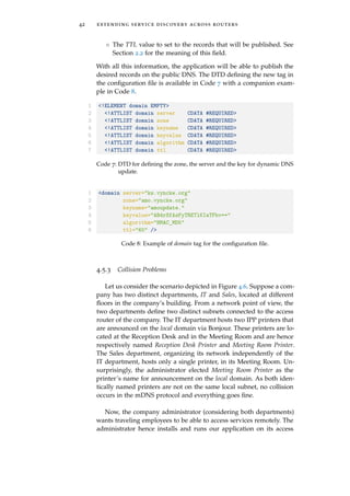
![36 extending service discovery across routers
◦ The resolved field is true only if we have found the hostname
hosting the service and at least one address for it.
◦ The announced field is true if the service has been announced on
the public DNS (see Section 4.5).
◦ As two services of the same type cannot have the same name,
the key of the table consists of the service name (and type)
and the interface on which it has been discovered (since ser-
vices with identical names could be discovered on different in-
terfaces).
In the addresses table:
◦ The ip field holds the IP version of the stored address.
◦ The key consists of the entire set of fields because a host could
have several addresses of the same IP version.
We provide the /decentralized/sql/user_init.sql script which creates
the two tables11. For this script to work, a service_discovery table must
exist. To simplify things, we also provide a /decentralized/sql/root_init.sql
script creating a user amo with password cisco123 with all privileges
on a service_discovery database. Consequently,
$ mysql -u root -p < root_init.sql
$ mysql -u amo -p < user_init.sql
may be used to properly initialize the MySQL database. This is done
by the setup.sh script12.
Figure 4.5 shows part of the content of both databases when run-
ning the application connected to the ULg network. The figure is
taken from the phpMyAdmin interface of XAMPP.
Note that, as mentioned in Section 3.1.3, for simplification, we only
consider public addresses. To do so, we use the is_private() method
of the netaddr Python package. If a private address is observed, the
daemon will act as if it had not seen it.
4.3.2 Coherency of the State
The daemon cannot operate properly if the database content is not
valid. Indeed, actions it will perform will depend on the database
content. For this reason, any MySQL request which fails will cause
the daemon to stop.
11 As recommended by Oracle [MySQL-Doc], we use the InnoDB storage engine.
12 As we use XAMPP for our tests, setup.sh uses /opt/lampp/lampp start to start the
MySQL server and /opt/lampp/bin/mysql to run MySQL. These must be changed to
be valid for other MySQL installations.](https://image.slidesharecdn.com/f38b3b0e-26b5-4b32-b4ae-c5c28b84993f-160124073825/85/thesis-48-320.jpg)
![38 extending service discovery across routers
whether to announce it or not. This is somehow similar to the situa-
tion a firewall experiences: it faces a packet and has to decide whether
to forward it or not. The solution adopted by firewalls is to navigate
into an access control list and perform the action specified by the first
rule matching the incoming packet [KR13]. We will here implement
a similar approach. The daemon will navigate through a list of rules
and as soon as a rule’s criteria are matched by the service, the dae-
mon will perform the action specified by the rule. If no matching rule
is found, the daemon default action will be not to publish the service.
For the sake of simplicity, for each rule, the user will have to spec-
ify a value for each attribute of the services table except resolved, an-
nounced and TXT. Indeed, the latter is a byte array, which is quite
cumbersome to compare with a user input string. The time needed to
implement such a feature is not worth it, as it is unlikely a user will
want to filter services based on their TXT record content. The value
specified by the user for an attribute should be a regular expression.
The Python re module is used to check if the regular expressions en-
tered by the user matches the given service. The regular expressions
syntax is described in the official re package documentation [Py-Doc].
Note that we do not allow to filter services based on their IP ad-
dress. There are two reasons for this. Firstly, addresses announcement
handling would be a far too troublesome task. Secondly, filtering a
service based on its address is supposed foolish. Indeed, addresses
are not supposed to be known in advance and hostnames are there to
serve a similar task on a long-term and more human-readable way.
As expected, the user will be able to configure the publication
rules in the configuration file14. The DTD lines defining such a possi-
bility are available in Code 5 with a companion example in Code 6.
The latter asks the application to publish only _http._tcp and _ftp._tcp
services. We see that the user can specify an optional rules tag which
must contain one or several service tags, each of them defining a rule.
The service tag attributes define the service and the content of the tag
defines the action to be performed. The DTD does not specify it, but
only allow and deny are allowed. Rules with another action will be
ignored. Note that, similarly to firewall ACLs, the order of the rules
is relevant.
This configuration facility is a very elegant solution. It allows the
user to apply fine filtering while keeping the configuration and the
implementation simple. It is indeed easy for the user to write an XML
file15 and so is it too for the program to parse an XML file and then go
disappears. Further information may be obtained in the fully documented code in
/decentralized/python/ServiceDiscovery.py.
14 Note that this will be also possible, and that is an important part, later via the GUI.
15 And it will even be easier when he will be able to edit the XML file using the GUI.](https://image.slidesharecdn.com/f38b3b0e-26b5-4b32-b4ae-c5c28b84993f-160124073825/85/thesis-50-320.jpg)
![4.5 announcing the registered services on the public domain 39
1 <!ELEMENT config (log,database,rules?)>
2 <!ELEMENT rules (service+)>
3 <!ELEMENT service (#PCDATA)>
4 <!ATTLIST service name CDATA #REQUIRED>
5 <!ATTLIST service type CDATA #REQUIRED>
6 <!ATTLIST service interface-name CDATA #REQUIRED>
7 <!ATTLIST service interface-ip CDATA #REQUIRED>
8 <!ATTLIST service hostname CDATA #REQUIRED>
9 <!ATTLIST service port CDATA #REQUIRED>
Code 5: DTD for defining the publication preferences.
1 <rules>
2 <service name=".*"
3 type="_((http)|(ftp))._tcp"
4 interface-name=".*"
5 interface-ip=".*"
6 hostname=".*"
7 port=".*">
8 allow
9 </service>
10 </rules>
Code 6: Example of rules tag for publishing only HTTP and FTP services.
through the list of rules when having to decide whether to announce
a service or not.
4.5 announcing the registered services on
the public domain
Before getting into practical considerations, let us introduce the
mechanisms available for updating a public DNS zone.
4.5.1 DNS Dynamic Update
[RFC1034], defining concepts and facilities of DNS, makes the as-
sumption that most of the data in the system will change very slowly
but says however that “the system should be able to deal with subsets
that change more rapidly”. Initially, all updates were indeed made as
edits to a zone’s master file [RFC2136]. In the DNS message format
header, a four bits OPCODE field is reserved to specify the kind of
query contained in the message (or the kind of query the message
answers). Initially, three values were possible: a standard query, an
inverse query and a server status request [RFC1035]. In order to al-
low dynamic DNS update, [RFC2136] specifies a new OPCODE value,
UPDATE, allowing to easily add or delete records from a specified
zone.](https://image.slidesharecdn.com/f38b3b0e-26b5-4b32-b4ae-c5c28b84993f-160124073825/85/thesis-51-320.jpg)
![40 extending service discovery across routers
This opcode uses the same sections formats as DNS but changes
the naming and uses of these (see Section 2.2). A DNS UPDATE mes-
sage is divided into five parts: a header, a zone section, a prerequi-
site section, an update section and an additional section. The header
section has the same role as in a classical DNS message. The zone
section specifies the zone to be updated. The three last sections con-
tain records and respectively specify the prerequisites which must be
satisfied, the update to be made if the prerequisites are satisfied and
possible additional data. The prerequisite section allows to ask for a
RRset16 to exist (value dependent or not), for a RRset not to exist, for
a name to be in use or for a name not to be in use. The update section
allows to add RRs to an RRset, delete an RRset, delete an RR from an
RRset or delete all RRsets from a name. The update is only performed
by the server if all prerequisites are verified.
This vanilla protocol exposes the system to corruption and poi-
soning if no precautions are taken to prevent anybody from editing
the zone. [RFC2136] recommends the protocol to be used with an au-
thentication technology such as IPsec or the mechanism defined in
[RFC2137] and which has been obsoleted by [RFC3007]. The latter
proposes to use TSIG or SIG(0) records (simply added to the DNS
message) to authenticate DNS requests. In this way, the server will
be able to identify who wants to edit the zone, and thereupon decide
whether or not to apply the changes, based on security preferences
defined by the administrator of the zone. The two following sections
describe how these security mechanisms actually work.
4.5.1.1 SIG(0)
SIG(0), defined in [RFC2931], is based on DNSsec. DNSsec is the
project launched by the IETF in 1994 to make DNS secure [Tan02].
It is based on public-key cryptography. Every zone has a public/pri-
vate key pair and signs the RRset it sends using its private key. This
signature is sent in a newly defined SIG record. Another new record
type, KEY, allows to store (inter alia) the public key and the algo-
rithm used for signing. The KEY records are supposed to be retrieved
securely (e.g., thanks to IPsec).
SIG(0) provides protection for DNS transactions and requests that
is not provided by DNSsec. Indeed, as mentioned in [RFC2931], the
latter provides “no protection for [...] DNS requests, no protection for mes-
sage headers on requests or responses, [...]”, which is what is required by
dynamic updates. To achieve requests authentication, a SIG(0) record
(similar to SIG) containing the signature of the request using the re-
quester private key is added to the message. The server, using the
16 A RRset is the name given to all the RRs having the same name, class and type
[RFC2136].](https://image.slidesharecdn.com/f38b3b0e-26b5-4b32-b4ae-c5c28b84993f-160124073825/85/thesis-52-320.jpg)
![4.5 announcing the registered services on the public domain 41
corresponding public key (correspondance based on a name), is then
able to check the authenticity and integrity of the message.
4.5.1.2 TSIG
Similarly, TSIG (Transaction Signature) can be used to “authenticate
DNS update requests as well as transaction responses” [RFC2845]. TSIG
is a lightweight alternative to SIG(0) since it is based on symmetric
cryptography which is faster than public-key cryptography. A TSIG
record is added at the end of the DNS request. This record contains,
inter alia, a key name, the message authentication code (MAC) and
the algorithm used to hash. Based on this, the recipient can verify the
integrity and authenticity of the message if it knows the key corre-
sponding to the given name.
BIND is the most widely used software for running DNS servers
[Conb]. The BIND latest version’s (9.10.1) reference manual [Cona]
mentions that BIND only partially supports SIG(0) while it provides
a full description of TSIG functionalities. As a consequence, we will
focus on TSIG which seems to be much more widely deployed.
4.5.2 Domain Declaration
The user of our application will have to provide the necessary in-
formation for the daemon to be able to publish the services on a
public DNS zone. This information includes:
◦ The name of the zone to update.
◦ The name of the name server to which the dynamic DNS up-
dates must be sent. It is up to the user to ensure that this server
is able to process the TSIG DNS update for the given zone.
◦ The key (the key value and the key name) and algorithm to be
used for signing update messages. Once more, it is up to the
user to ensure that the provided key and algorithm will be al-
lowed to fully update the zone. Indeed, [RFC3007] specifies that
servers should be able to restrict updates by RR types or do-
main names. The user must hence ensure that the provided key
will be allowed to update the specified zone and the necessary
record types. [RFC4635] specifies the algorithms that implemen-
tations supporting TSIG must or may implement. The possible
algorithms are hmac-md5, gss-tsig, hmac-sha1, hmac-sha224, hmac-
sha256, hamc-sha384 and hmac-sha512. In Section 4.5.4, we will
choose to use the dnspython package. The latter supports all of
the above algorithms except gss-tsig. We will thus allow any of
these except gss-tsig, which is not a problem since it is specified
as optional.](https://image.slidesharecdn.com/f38b3b0e-26b5-4b32-b4ae-c5c28b84993f-160124073825/85/thesis-53-320.jpg)
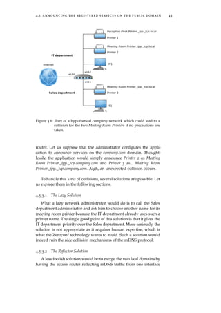
![44 extending service discovery across routers
to the other. Avahi provides such a mechanism thanks to its enable-
reflector option (See Section 4.2.3.1).
Reflecting the traffic on all interfaces would solve the problem be-
cause the mDNS protocol would automatically take care of the colli-
sion, forcing one of the printers to rename itself. However, this is not
appropriate either. Let us suppose that, by the mDNS collision han-
dling mechanisms, Printer 3 announces itself as Meeting Room Printer
#217 while Printer 2 does not change its name. The S1 user in the
Sales department would see two Meeting Room printers. How could
he know which printer is indeed in the Sales department’s meeting
room? How could he even know that one of the printer is actually
not in the Sales department? Similarly, how could he know that the
Reception Desk Printer he sees is not in the Sales department?
Such a solution would not allow the users to distinguish services
from different subnets, which can be quite problematic as this sim-
ple18 example shows.
4.5.3.3 The Renaming Solution
Another solution would be for our application to rename the ser-
vices it announces publicly to reflect the subnet to which they belong.
The router could then announce Printer 2 and Printer 3 respectively as
Meeting Room Printer (eth2)._ipp._tcp.company.com and Meeting Room
Printer (eth1)._ipp._tcp.company.com. Such a solution would leave no
room for any collision while still keeping both subnets completely
separated and distinguishable. Several problems however arise.
Firstly, the service name length is increased. Indeed, we append
the name of an interface to it. [RFC1035] limits the total length of a
DNS name to 255 octets, with up to 63 octets per label. Depending
on the initial service name, appending an interface name to it could
lead to an invalid name’s length19. A solution would be to remove
the trailing octets of the service name in order to reduce the size of
the name, but this could lead to collisions and is not, at least for
presentation reasons, a good idea. As it is impossible to handle such
a problem automatically, the application can simply log an error and
not announce the service if the new name is not valid anymore. It
will then be up to the administrator or user to fix the problem.
17 IT still has priority over Sales.
18 Imagine a scenario with more than two different subnets.
19 Note that this could have occurred even without renaming the service. Indeed, as
we always convert the local domain to the public one (company.com for example), the
total length of the DNS name can change, and hence increase, possibly leading to an
invalid name.](https://image.slidesharecdn.com/f38b3b0e-26b5-4b32-b4ae-c5c28b84993f-160124073825/85/thesis-56-320.jpg)
![4.5 announcing the registered services on the public domain 45
Secondly, the new name, consisting of the concatenation of the ser-
vice name and the corresponding interface name, is not very nice
and comprehensible. Indeed, the remote employee would need to
know that eth2 corresponds to the IT department and eth1 to the
Sales department. Therefore, via the configuration file, we can allow
the user to choose, for each interface, the string to append to the ser-
vice name. The DTD defining the new tag is available in Code 9. The
example of configuration in Code 10 would lead to the names Meet-
ing Room Printer (IT)._ipp._tcp.company.com and Meeting Room Printer
(Sales)._ipp._tcp.company.com which are much more comprehensible.
1 <!ELEMENT interface EMPTY>
2 <!ATTLIST interface name CDATA #REQUIRED>
3 <!ATTLIST interface alias CDATA #REQUIRED>
Code 9: DTD for defining the alias of an interface.
1 <interface name="eth2" alias=" (IT)" />
2 <interface name="eth1" alias=" (Sales)" />
Code 10: Example of tags to rename interfaces.
Thirdly, we include the name of the interface (or an alias of it) be-
cause the mDNS traffic on each interface are completely independent.
However, within a single interface, there also exist two independent
mDNS traffics: one on IPv4 and one on IPv6. Indeed, services an-
nounced using the IPv6 mDNS multicast address will not be seen
by hosts observing only the IPv4 multicast address, and vice-versa.
Consequently, two services with the same names could be defined on
the same interface, but using different IP versions. In order to avoid
such collisions, the daemon can hence also add the IP version to the
service name. As for the interface name, we can give the possibility
to the user to choose an alias for both IP versions. The DTD defining
the new tag is available in Code 11. The new name of the service will
consist in the initial name to which we append the interface name
and then the IP version. Code 12 could thus lead to names such as
Meeting Room Printer [IT:v6] and Meeting Room Printer [Sales:v6].
1 <!ELEMENT ip EMPTY>
2 <!ATTLIST ip version CDATA #REQUIRED>
3 <!ATTLIST ip alias CDATA #REQUIRED>
Code 11: DTD for renaming the IP versions.
Fourthly, let us consider that Printer 2 announces itself both on
IPv4 and IPv6. The solution would lead to two services announced](https://image.slidesharecdn.com/f38b3b0e-26b5-4b32-b4ae-c5c28b84993f-160124073825/85/thesis-57-320.jpg)
![46 extending service discovery across routers
1 <ip version="4" alias=":v4]" />
2 <ip version="6" alias=":v6]" />
3 <interface name="eth2" alias=" [IT" />
4 <interface name="eth1" alias=" [Sales" />
Code 12: Example of tags to rename interfaces and IP versions.
on the public DNS, whereas only one really exists. Is there a solution
to avoid this? No. In fact, from a Bonjour point of view, there are
indeed two distinct services. It is impossible to, generically, check if
the services are in fact the same or not. Indeed, even the IP address
cannot be used, as two different services could be hosted by the same
IP address. Moreover, when browsing locally using the vanilla DNS-
SD protocol, the service would also appear twice, so this problem is
inherent to the Bonjour technology.
Fifthly, we have only talked about the renaming of the service
names but exactly the same collision problem arises for hostnames.
Nevertheless, hostnames cannot be changed freely as can be services
names. However, the hostnames are less subject to presentation crite-
rion. Consequently, hostnames can be renamed as follows: hostname +
"-" + if_name + "-v" + if_ip, leading for example to printer2-eth2-v6.
Finally and foremostly, in the case of a system with multiple rou-
ters (which is not the case in our simple scenario) collisions can also
occur between those different routers. We must hence also append
the router name to the service name and to the hostname and allow
the administrator to configure the appended strings. This information
can be added to the config tag, as shown in Codes 13 and 14. The name
attribute is used for hostname renaming and the alias attribute for ser-
vice name renaming. Such a configuration could lead to names such
as Meeting Room Printer @ Brussels [IT:v6]20 and Meeting Room Printer
@ London [IT:v6], and to hostnames such as printer2-brussels-eth2-v6.
However, several instances of the application will manage the com-
pany.com zone. Such a situation is unaffordable. Indeed, an instance of
the application must always know all the services announced on the
zone in order to know when to remove records announcing service
types. Are there still printers in the domain? The application could
lookup the DNS zone to obtain the answer but this is a bit heavy
and could lead to concurrency problems. Indeed, let us consider the
following scenario.
◦ Router 1 deletes its last printer. It sees that there is no more
printers in the zone.
◦ In the meantime, Router 2 adds a new printer.
20 The router alias name is added between the initial name and the interface alias.](https://image.slidesharecdn.com/f38b3b0e-26b5-4b32-b4ae-c5c28b84993f-160124073825/85/thesis-58-320.jpg)
![4.6 graphical user interface 49
ods to add and remove records and services and to clear all the ser-
vices from a zone.
4.5.5 Coherency of the State
As with the MySQL database, the daemon cannot operate prop-
erly if the public DNS content is not valid. To ensure this, we will
hence use TCP for our Dynamic DNS updates. Indeed, DNS is usu-
ally used with UDP, but it does not guarantee that all our requests
will finally reach the name server. Moreover, the use of TCP is ad-
vised by [RFC2136] and [RFC5966] obliges any DNS implementation
to support TCP.
Besides, as coherency of the DNS content must be maintained, the
daemon will stop at any DNS update failure.
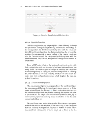
4.6 graphical user interface
In this section, we will develop the graphical user interface (GUI)
that will allow an administrator to easily configure the daemon. As
the daemon is to be run on a router, it will most probably be config-
ured remotely. Currently, this configuration is possible by manually
editing the /etc/service-discovery/config.xml, which can be done using
the vim tool in an ssh session. This however requires to be able to deal
with the XML syntax and to be familiar with the Linux CLI. The goal
of this section is somewhat to hide the details of the config.xml file
with a user-friendly interface so that the average Joe can still easily
configure the application.
4.6.1 A Web Server
The basic approach to providing a remotely accessible GUI is a
web interface consisting of pages accessible using the Hypertext Trans-
fer Protocol (HTTP). The HTTP protocol is implemented by web brow-
sers such as Google Chrome, Internet Explorer, Mozilla Firefox, Opera
or Safari. Nowadays, such browsers are available on almost any com-
puting device (smartphone, tablet, laptop, desktop computer). Hence,
implementing the GUI as a web interface allows the application to be
configurable by numerous different devices as long as they are able to
reach the server and interact with it using a web browser. This choice
is nicely summarized in the following quote: “web-based applications
have actually simplified sysadmins’ jobs. [...] features like AJAX [...] and
dynamic HTML bring users the functionality and responsiveness of locally
installed applications but relieve sysadmins of a multitude of deployment](https://image.slidesharecdn.com/f38b3b0e-26b5-4b32-b4ae-c5c28b84993f-160124073825/85/thesis-61-320.jpg)
![50 extending service discovery across routers
headaches: the only software required on the client side is a web browser.”
[Nem+10].
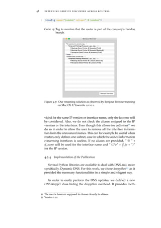
The router running the daemon must hence also run an HTTP
server hosting the interface pages. Several HTTP servers are available,
but as advised by Nemeth et al. [Nem+10], we will use an Apache
server, which, as of January 2015, is the leading HTTP server on the
Web [Neta]. For our tests, we used Apache 2.4.10 installed via XAMPP.
Following the discussion of Section 4.2.3.6, the server must run as the
user sd-gui of the group sd. This can be configured by adding Code
16 in the Apache httpd.conf file.
1 User sd-gui
2 Group sd
Code 16: Configuration of an Apache server to run as the user sd-gui of the
group sd.
The interface pages are available in the /decentralized/www/ direc-
tory of this work’s archive. All the files are sufficiently commented
but we will still, herebelow, sketch a portrait of the interface struc-
ture.
4.6.2 Authentication
An astute reader will have probably be astonished reading the in-
troduction hereabove in which we mention that the application can
be configured by any device able to connect to the HTTP server. This
feature gives the administrator the freedom to configure the daemon
from any web browser but, as you are currently thinking, we must
ensure that only the administrator, or another authorized people, is
actually able to configure the application. The Apache server config-
uration file allows to define a security policy determining who can
access which files. However, we rather provide .htaccess and .htpasswd
files that achieve exactly the same goal. Using those files rather than
the usual configuration of the Apache web server ensures that, when
getting the interface files from the archive, the interface will already
be secured. Once settled, the content of .htaccess can be inserted into a
Directory clause in the httpd.conf configuration file of Apache in order
to achieve the same security goal. Note however that, in the .htaccess
file, the password file path must be absolute. Hence, the latter must
be changed based on where the web pages are stored on the machine.
Thus, we provide the /decentralized/www/.htaccess and /decentralized/
www/.htpasswd files which will require the user to enter a username](https://image.slidesharecdn.com/f38b3b0e-26b5-4b32-b4ae-c5c28b84993f-160124073825/85/thesis-62-320.jpg)
![4.6 graphical user interface 51
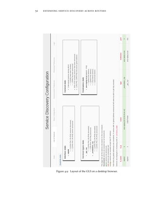
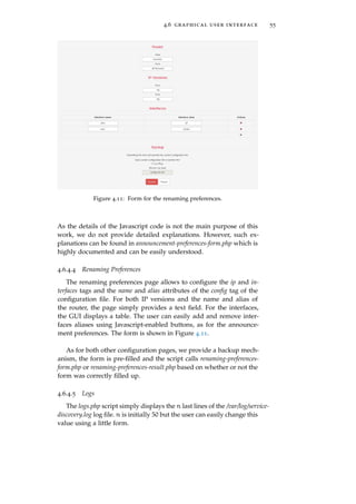
Figure 4.8: Layout of the GUI on a tablet browser.
and a password when connecting to the GUI. The .htpasswd file de-
fines a single amo user with cisco123 password.
4.6.3 Bootstrap
After having suitably configured Apache, let us now take a look at
the implementation of the interface. The interface has been developed
using HTML, CSS, PHP and Javascript languages. In order to facili-
tate the development of the visual aspect of the interface, we used
Bootstrap23, “a framework for developing responsive, mobile first projects
on the web” [Boo]. Bootstrap comes as CSS, Javascript and font files.
Those are included in the /decentralized/www/style/bootstrap/ directory.
The main advantage of using Bootstrap is that it allows to easily
develop responsive websites. That is, the layout is adapted depend-
ing on the screen size on which it is displayed, as shown with the
navigation bar and stats boxes in Figures 4.8 and 4.9. As our GUI is
accessible from any computing device (see Section 4.6.1), using Boot-
strap ensures that all these devices will get a nice layout tailored to
their screen size.
23 Version 3.3.2.](https://image.slidesharecdn.com/f38b3b0e-26b5-4b32-b4ae-c5c28b84993f-160124073825/85/thesis-63-320.jpg)


![5.1 daemon 59
1 <?xml version="1.0"?>
2 <!DOCTYPE config SYSTEM "config.dtd">
3 <config>
4 <log level="debug"/>
5 <update rate="30"/>
6 <domain name="amo.vyncke.org"/>
7 </config>
Code 18: Configuration file of the centralized application to log messages
for the amo.vyncke.org domain and to check for a change in the
system every 30 seconds.
5.1.2 Detecting Changes in the System
5.1.2.1 Preferences of the User
As the preferences of the user are specified in a configuration file,
in order to detect a change in the configuration, we can compare the
content of the file between two iterations. However, this process is
too tedious. A more efficient solution is to compare the modification
time of the file from one iteration to the other. If the file has been
modified since the last generation of the firewall rules, we consider
that a change has occurred and we regenerate the rules3.
5.1.2.2 Content of the DNS Zone
How will a change in the DNS zone be detected without having
to fetch all the records and compare them to the ones fetched at the
previous iteration? We will use the DNS SOA record.
The SOA record is presented in [RFC1034] as an identifier of the
start of a zone of authority. Each zone (see Section 2.2) must own
a single SOA RR that describes zone management parameters. The
data associated to an SOA record is composed of several fields. Those
specify authoritative information about the zone including the pri-
mary name server, the email of the administrator, a version number
of the zone content, and several timers relating to refreshing the zone
[RFC1035].
In order to detect a change in the zone content, we will use the
serial field of the SOA record, which contains a version number of
the zone content. As mentioned in [RFC1034], “[...] the SERIAL field
in the SOA of the zone is always advanced whenever any change is made
to the zone.” Thus, if we observe that the value of the serial field has
increased, we may conclude that a change has occurred in the zone.
3 Note that the configuration file does not consist only of the security preferences of
the user. Hence, the daemon might consider that a change occurred while the rules
are still the same. However, this is not a major issue.](https://image.slidesharecdn.com/f38b3b0e-26b5-4b32-b4ae-c5c28b84993f-160124073825/85/thesis-71-320.jpg)
![60 security and access policies
However, [RFC1982] highlights the fact that the serial number can
wrap and defines a serial number arithmetic, i.e. an addition and a
comparison operator. The latter operator allows, from two different
serial numbers, to infer which one corresponds to the newest version
of the zone. Nevertheless, we will infer that a change has occurred
in the zone if the serial number is simply different from the one ob-
served in the previous iteration. Hence, we will not rely on the op-
erators defined in [RFC1982]. Indeed, this operator is to be used to
compare two serial numbers of the zone and to know which one pre-
dates the other. Here, we simply want to know if the content of the
zone is different or not from the content used to generate the current
firewall rules. Consequently, simply checking if the serial number is
the same or not is sufficient.
5.1.3 Defining Security Preferences
We want the administrator of the system to be able to define pref-
erences as easily and as generally as possible. Easily means that the
interface should be user-friendly and that the user should not have
to deal with IP addresses, port numbers and technical stuff. Gener-
ally means that the user should be allowed to define global rules for
the entire system that would be automatically particularized to each
router (if necessary).
To do so, the administrator will be asked to provide an ordered
list of rules defining who (the subject) can or cannot access what (the
object). Let us see how he will be asked to specify the subject and the
object of the rules.
Subject. Unfortunately, the single way to identify sources in the Inter-
net is to use IP addresses. Consequently, the user will have to
provide an IP address range (an IP address and a prefix length)
defining which source IP addresses will be concerned by the
rule.
Object. The services concerned by a rule will have to be identified us-
ing regular expressions for the name and the type of the service.
Moreover, we will allow the administrator to specify if the rule
must be applied only to a given router or to all routers (then
using the * joker) involved in the system.
The DTD defining the tags allowing to define such rules is shown
in Code 19. An example of security preferences is shown in Code 20.](https://image.slidesharecdn.com/f38b3b0e-26b5-4b32-b4ae-c5c28b84993f-160124073825/85/thesis-72-320.jpg)
![5.1 daemon 61
1 <!ELEMENT rules (rule+)>
2 <!ELEMENT rule (#PCDATA)>
3 <!ATTLIST rule src-address CDATA #REQUIRED>
4 <!ATTLIST rule src-prefix-length CDATA #REQUIRED>
5 <!ATTLIST rule router CDATA #REQUIRED>
6 <!ATTLIST rule name CDATA #REQUIRED>
7 <!ATTLIST rule type CDATA #REQUIRED>
Code 19: DTD for defining the security rules.
1 <rules>
2 <rule src-address="2001:db8:0:85a3::ac1f:8001"
3 src-prefix-length="32"
4 name=".*Room.*" type=".*" router="london">
5 allow
6 </rule>
7 <rule src-address="2015:db8:0:85a3::ac1f:8001"
8 src-prefix-length="64"
9 name=".*Desk.*" type=".*" router="brussels">
10 allow
11 </rule>
12 <rule src-address="1993:db8:0:85a3::ac1f:8001"
13 src-prefix-length="96"
14 name=".*" type=".*" router="*">
15 deny
16 </rule>
17 </rules>
Code 20: Example of security rules.
5.1.4 Generating the Firewall Rules
Based on the list of rules and on the content of the DNS zone, the
centralized application will have to generate a list of firewall rules.
As mentioned in Section 3.2, we will simply generate ip[6]tables rules
in one file per router involved in the system. Let us first review the
iptables tool.
5.1.4.1 iptables
iptables [Netb] is a userspace command line program that can be
used to configure the packet filtering ruleset on the Linux 2.4 and
later kernels. More specifically, it allows a system administrator to
configure a firewall, a NAT, or modify the content of the packets on
the system. The iptables tool comes with its ip6tables counterpart used
to handle IPv6 packets.
In order to perform those tasks, network packets go through three
tables in the following order [Nem+10]:
◦ mangle. It is used to modify or alter the content of packets.](https://image.slidesharecdn.com/f38b3b0e-26b5-4b32-b4ae-c5c28b84993f-160124073825/85/thesis-73-320.jpg)
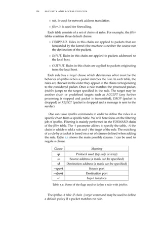
![5.1 daemon 63
5.1.4.2 Retrieving Input Interfaces
As shown in Table 5.1, when adding a rule, we may specify an
input interface. If this option is not specified, the rule will be applied
to all the interfaces of the machine [man]. This is not efficient. Indeed,
we do not want rules to be applied to all interfaces. In particular,
it is useless to apply rules to the private interface(s) of the access
router. Consequently, we have to specify the -i option. However, the
centralized application does not know the interfaces of the routers
involved in the system. To solve this problem, we will slightly modify
the decentralized application and ask the user of it to specify the
interfaces on which he wants the rules to be applied. As expected,
this information will have to be specified in the configuration file.
To do so, we add a public-interfaces attribute to the config tag of the
configuration file of the decentralized application. For example, Code
21 can be used to specify that the rules have to be applied to interfaces
eth0 and eth1. This can be useful in case of multi-homing for example.
The decentralized application will then publish a TXT record to tell
the centralized application which interfaces have to be configured.
The source of the TXT record will be the subdomain of the router and
the data public=X where X is a list of the comma-separated interfaces
to be considered. Thanks to this, the centralized application will be
able to retrieve the interfaces on which to apply the rules by issuing
a classical DNS query.
1 <config name="brussels" alias=" @ Brussels"
2 public-interfaces="eth0,eth1">
3 ...
4 </config>
Code 21: Configuring the decentralized application to announce to the cen-
tralized application that rules must be applied on eth0 and eth1
interfaces.
5.1.4.3 Algorithm
In this section, we present the algorithm used to translate the
DNS content and the user preferences into iptables rules. Algorithm
1 shows a pseudo-code of the algorithm. For each router, we create
a file named iptables_router.sh where router is the name (subdomain
label) of the router. For simplicity, we save this file in the /etc/policy-
manager/ directory because we already have the necessary permis-
sions. We start by removing from the rules those that do not concern
the current router. To do so, we keep only the rules with * or the name
of the router as router attribute. Once this is done, we go through the
remaining rules. For each one of them, we keep a list of the services](https://image.slidesharecdn.com/f38b3b0e-26b5-4b32-b4ae-c5c28b84993f-160124073825/85/thesis-75-320.jpg)
![64 security and access policies
rules ← List of rules from the configuration file
services ← List of the services in the DNS zone
for each router do
interfaces ← Public interfaces from DNS TXT record
Create iptables file
rules ← rules without rules specifically for another router
for each rule in rules do
for each service matching rule do
for each interface in interfaces do
for each address in service.addresses do
Add iptables rule to file if not duplicate
Set default forwarding behavior to DROP
Algorithm 1: Translating the DNS subdomain content and the user prefer-
ences into iptables rules.
matching the rule4. For each service in this list, we establish an ipt-
ables rule for each interface and for each address of the service. The
rule is built as follows.
◦ iptables or ip6tables will be chosen based on the IP version of the
source of the rule and of the address of the service.
◦ -t filter and -A FORWARD will always be specified to add the
rule to the FORWARD chain of the filter table.
◦ The protocol after the -p clause will be tcp for service types
ending in _tcp and !tcp for service types ending in _udp. Indeed,
[RFC6763] mentions that “The second label is either "_tcp" (for
application protocols that run over TCP) or "_udp" (for all others).”
Hence, _udp does not mean UDP but rather not TCP.
◦ The source of the rule after the -s clause will consist of the ad-
dress and the prefix length specified by the administrator in the
rule.
◦ -i will be followed by the current input interface considered.
◦ -d will be followed by the address of the service (if the service
has several addresses, we must create one rule for each address)
and --dport by the port of the service.
◦ The action after the -j clause will be ACCEPT or DROP depend-
ing on whether the action in the rule is allow or deny.
4 To match a rule, beyond matching the attributes of the rule, the IP version of the
service’s address must be the same as the IP version of the source’s address in the
rule.](https://image.slidesharecdn.com/f38b3b0e-26b5-4b32-b4ae-c5c28b84993f-160124073825/85/thesis-76-320.jpg)
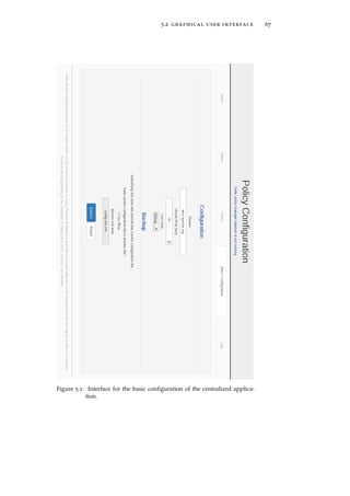
![6R E L AT E D W O R K A N D
C O N C L U S I O N S
In order to emphasize the contributions of this work, we will first
introduce related work conducted by the Internet Engineering Task
Force (IETF) on extensions to DNS-SD. Then, in a final section, we
will summarize the achievements and limitations of our application.
6.1 related work
At the IETF, the dnssd working group [dnssd-wg] is working on
extensions for providing a scalable DNS-SD protocol. They noticed
that people wanted to use the service provided by mDNS/DNS-SD
for service discovery across routers.
In a first document [Lyn+15], they define the requirements for en-
abling service discovery beyond the local link. They call such an ex-
tension scalable DNS-SD (SSD). They highlight the possibility of con-
flicts among several subnets (as we have done in Section 4.5.3) and
they mention but do not tackle the access control problem we covered
in Chapter 5.
In a second document [Che14], they describe a solution to the prob-
lem. This solution specifies a type of proxy, called a Hybrid Proxy,
using mDNS to discover records on the local link and then making
those records visible in the unicast DNS namespace. Their solution
is conceptually different from ours. They assume that each link has
its own unique DNS domain name (which solves the confict problem
of Section 4.5.3 similarly to our state exchange solution of Section
3.1.2.2) and that the Hybrid Proxy is the authoritative name server
for that domain. This requires NS records to be used in order to del-
egate ownership of each defined subdomain to the corresponding
Hybrid Proxy. To answer a unicast DNS request, the proxy queries
the local link using mDNS. Such a mechanism allows to easily pro-
vide late binding but it unveils many complications. Indeed, as they
say: “it raises the question of how long the Hybrid Proxy should wait to be
sure that it has received all the Multicast DNS answers it needs to form a
complete Unicast DNS response.” To solve the problem, they consider
the usage of DNS long-lived queries. However, those must be speci-
fied on the client-side. Hence, the document must consider the case
69](https://image.slidesharecdn.com/f38b3b0e-26b5-4b32-b4ae-c5c28b84993f-160124073825/85/thesis-81-320.jpg)
![70 related work and conclusions
when this type of query is not used. Compared to their work, the so-
lution described in this thesis tackles the problem differently and the
solutions are complementary as they might be used in different cases.
However, we think that our solution is ligther as we do not require
to run a complete DNS server and to configure it as authoritative
for its zone. They mention using DNS Updates but they think that
this is too onerous. However, they consider configuring every device
with the DNS Update credentials to permit automatic updates. They
do not mention our solution, which simply consists in configuring a
single device, the access router, observing the local link. They also
mention that IPv4 and IPv6 local links can be different and lead to
conflicts. To solve this problem, they plan to have a mechanism “to
’stitch’ together these two unrelated ".local." zones so that they appear as
one. Such mechanism will need to be able to differentiate between a dual-
stack (v4/v6) host participating in both ".local." zones.” To do so, they
could leverage the work of Beverly and Berger [BB15] trying to know
whether two IPv4 and IPv6 addresses belong to the same machine or
not. In our work, we developed an already well functioning solution
(the renaming and subdomain solutions) for this problem.
Compared to us, they allow subdomains to contain other charac-
ters than simply letters, digits and hyphens. However, as hostnames
cannot include such characters, the Hybrid Proxy must support two
subdomains delegated to it: one for hostnames and the other for the
PTR, SRV and TXT records. Although this enables the usage of much
more elegant names for subdomains, the way of solving the problem
is, for us, not very elegant.
6.2 conclusions
In the first part of this work, we tried to allow local services to
be discovered from anywhere in the Internet. Those services are ini-
tially announced using the Zeroconf technology, i.e. the mDNS and
DNS-SD protocols. As those protocols are based on DNS, we chose to
extend service discovery across routers by using the public DNS in-
frastructure. More precisely, the so-called decentralized application1,
which runs on the access router of a network willing to enjoy the ser-
vice, observes the local services using Avahi and publishes them on
a public DNS domain as DNS-SD services. This way, any user able
to contact the DNS infrastructure will be able to discover the services
using a DNS-SD browser. Doing so, we had to pay particular atten-
tion to collisions among services defined by different routers, or even
among services from different local links defined by a single access
router. To do so, we implemented an elegant subdivision of services
into subdomains corresponding to the different access routers, along
1 2098 lines of Python code.](https://image.slidesharecdn.com/f38b3b0e-26b5-4b32-b4ae-c5c28b84993f-160124073825/85/thesis-82-320.jpg)
![6.2 conclusions 71
with a mechanism allowing the administrator to rename services pub-
lished on the public DNS.
The second part of the thesis was devoted to the development of
a so-called centralized application2 configuring routers involved in
the system in order to implement a global security policy defined by
the administrator. For simplicity, we did not implement the complete
configuration process and the application simply outputs files con-
taining iptables rules. To do so, we developed an algorithm producing
those rules based on the user preferences and on the content of the
DNS domain. Every x seconds, we look for changes in one of the lat-
ter two and execute the algorithm only if a change has been detected.
This detection is performed looking at the serial of the SOA record of
the zone and at the modification time of the configuration file. Con-
sequently, the check is efficient. However, we could have improved
this mechanism. The idea would be to be notified of a change of the
DNS content, rather than looking for one. To do so, we could have
exploited the DNS notify mechanism defined in [RFC1996] by which
a master server is asked to advise other machines when the content
of the zone changes.
Finally, for both the centralized and the decentralized applications,
we developed a user-friendly GUI3 allowing the administrator to eas-
ily configure its application.
To test and validate our system, we deployed the application on
a Fedora Core 20 (Heisenbug) 64 bits Linux distribution in the Uni-
versity the Liège network in different buildings and during entire
days. Due to the high number of Bonjour services announced4 and
due to their high variability5, this network provides an ideal testbed
to confront our application to many special scenarios and race con-
ditions. Such a testing methodology allowed us to discover several
minor bugs unveiled in rare cases. Now that both the decentralized
and the centralized applications operate faultlessly on such a network
for several days, we can confidently consider that they will also oper-
ate properly on any other network. Note that the correctness of the
iptables rules generated has only been checked manually. Indeed, as
mentioned in Section 3.2, we are not able to implement them on real-
life access routers. A more thorough testing procedure could have
2 619 lines of Python code.
3 1699 lines of PHP, HTML and CSS code for the decentralized GUI and 955 lines of
PHP, HTML and CSS code for the centralized GUI.
4 Indeed, ULg LANs are populated with a huge number of services (418 when ob-
served on 11th February 2015 at 15:19 in the B31 building, and 503 when observed
on 13th May 2015 at 11:26 in the same B31 building).
5 Most of the services are announced by students laptops. As students often connect
and disconnect from the network (when entering or leaving a course or the library),
we observe many Bonjour services coming and going.](https://image.slidesharecdn.com/f38b3b0e-26b5-4b32-b4ae-c5c28b84993f-160124073825/85/thesis-83-320.jpg)
![72 related work and conclusions
been conducted by deploying the application on netkit, a virtual net-
work emulator [PR08]. In such a virtual environment, access routers
are Linux machines and we could have installed the iptables rules in
order to test them.](https://image.slidesharecdn.com/f38b3b0e-26b5-4b32-b4ae-c5c28b84993f-160124073825/85/thesis-84-320.jpg)


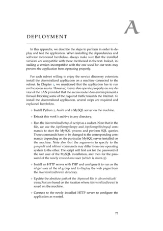
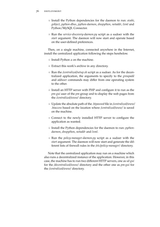
![BB I B L I O G R A P H Y
[BB15] R. Beverly and A. Berger. “Server Siblings: Identify-
ing Shared IPv4/IPv6 Infrastructure via Active Fin-
gerprinting.” In: Proc. Passive and Active Measurement
Conference (PAM) (May 2015).
[Boo] Bootstrap Web Page. url: http://getbootstrap.com/
(visited on Jan. 31, 2015).
[CS06] S. Cheshire and D. Steinberg. Zero Configuration Net-
working: The Definitive Guide. 1st ed. O’Reilly Media,
Inc., 2006.
[Che05] S. Cheshire. Zero Configuration Networking with Bon-
jour. Google Tech-Talks. Nov. 2005. url: http : / /
www.youtube.com/watch?v=ZhtZJ6EsCXo (visited
on Nov. 8, 2014).
[Che14] S. Cheshire. Hybrid Unicast/Multicast DNS-Based Ser-
vice Discovery. Internet-Draft draft-ietf-dnssd-hybrid-
00. IETF Secretariat, 2014. url: http://www.ietf.
org/internet-drafts/draft-ietf-dnssd-hybrid-
00.txt.
[Cona] Internet Systems Consortium. BIND 9 Administrator
Reference Manual. url: ftp://ftp.isc.org/isc/
bind9/cur/9.10/doc/arm/Bv9ARM.pdf (visited on
Nov. 20, 2014).
[Conb] Internet Systems Consortium. BIND. url: http://
www.isc.org/downloads/bind/ (visited on Nov. 20,
2014).
[Dbua] D-Bus Bindings. Aug. 2014. url: http://www.freedesktop.
org/wiki/Software/DBusBindings/ (visited on Dec. 29,
2014).
[Dbub] D-Bus Documentation. Feb. 2015. url: http://dbus.
freedesktop.org/doc/ (visited on Mar. 18, 2015).
[Dbuc] Introduction to D-Bus. July 2013. url: http://www.
freedesktop.org/wiki/IntroductionToDBus/ (vis-
ited on Dec. 29, 2014).
[Fre] freedesktop.org Project Home Page. May 2013. url: http:
//www.freedesktop.org/ (visited on Dec. 29, 2014).
77](https://image.slidesharecdn.com/f38b3b0e-26b5-4b32-b4ae-c5c28b84993f-160124073825/85/thesis-89-320.jpg)
![78 bibliography
[IG04] The IEEE and The Open Group. IEEE Std 1003.1. The
Open Group Base Specifications Issue 6. The Open
Group Base Specifications, 2004. url: http://pubs.
opengroup.org/onlinepubs/009695399/basedefs/
signal.h.html.
[Int03] InterNIC. InterNIC FAQs on the Domain Names, Regis-
trars, and Registration. Sept. 2003. url: http://www.
internic.net/faqs/domain-names.html (visited on
Oct. 23, 2014).
[KR13] J. Kurose and K. Ross. Computer Networking: A Top-
Down Approach. 6th ed. Pearson Education, Inc., 2013.
[Lyn+15] K. Lynn et al. Requirements for Scalable DNS-SD/mDNS
Extensions. Internet-Draft draft-ietf-dnssd-requirements-
06. IETF Secretariat, 2015. url: http://www.ietf.
org/internet-drafts/draft-ietf-dnssd-requirements-
06.txt.
[MySQL-Doc] Oracle Corporation and/or its affiliates. MySQL 5.6
Reference Manual. url: http://dev.mysql.com/doc/
refman/5.6/en/index.html (visited on Nov. 17,
2014).
[Nem+10] E. Nemeth et al. UNIX and Linux System Administra-
tion Handbook. 4th ed. Prentice Hall, 2010.
[Neta] Netcraft. January 2015 Web Server Survey. url: http:
//news.netcraft.com/archives/category/web-
server-survey/ (visited on Jan. 31, 2015).
[Netb] Netfilter. The Netfilter.org iptables Project. url: http:
//www.netfilter.org/projects/iptables/ (visited
on Apr. 13, 2015).
[PEP0001] B. Warsaw et al. PEP Purpose and Guidelines. PEP 0001.
PEP Editors, Apr. 2013. url: http://legacy.python.
org/dev/peps/pep-0001.
[PEP3143] B. Finney. Standard daemon process library. PEP 3143.
PEP Editors, Jan. 2009. url: http://legacy.python.
org/dev/peps/pep-3143.
[PR08] M. Pizzonia and M. Rimondini. “Easy Emulation of
Complex Networks on Inexpensive Hardware.” In:
Proc. 4th International Conference on Testbeds and Re-
search Infrastructures for the Development of Networks
& Communities (TRIDENTCOM) (May 2008).
[Py-Doc] Python Software Foundation. Python 2.7.8 documenta-
tion. url: https://docs.python.org/2/.](https://image.slidesharecdn.com/f38b3b0e-26b5-4b32-b4ae-c5c28b84993f-160124073825/85/thesis-90-320.jpg)
![bibliography 79
[RFC1034] P. Mockapetris. Domain Names - Concepts and Facilities.
RFC 1034. RFC Editor, Nov. 1987. url: http://www.
rfc-editor.org/rfc/rfc1034.txt.
[RFC1035] P. Mockapetris. Domain Names - Implementation and
Specification. RFC 1035. RFC Editor, Nov. 1987. url:
http://www.rfc-editor.org/rfc/rfc1035.txt.
[RFC1982] R. Elz and R. Bush. Serial Number Arithmetic. RFC
1982. RFC Editor, Aug. 1996. url: http://www.rfc-
editor.org/rfc/rfc1982.txt.
[RFC1996] P. Vixie. A Mechanism for Prompt Notification of Zone
Changes (DNS NOTIFY). RFC 1996. RFC Editor, Aug.
1996. url: http : / / www . rfc - editor . org / rfc /
rfc1996.txt.
[RFC2131] R. Droms. Dynamic Host Configuration Protocol. RFC
2131. RFC Editor, Mar. 1997. url: http://www.rfc-
editor.org/rfc/rfc2131.txt.
[RFC2136] P. Vixie et al. Dynamic Updates in the Domain Name Sys-
tem (DNS UPDATE). RFC 2136. RFC Editor, Apr. 1997.
url: http://www.rfc-editor.org/rfc/rfc2136.
txt.
[RFC2137] D. Eastlake 3rd. Secure Domain Name System Dynamic
Update. RFC 2137. RFC Editor, Apr. 1997. url: http:
//www.rfc-editor.org/rfc/rfc2137.txt.
[RFC2782] A. Gulbrandsen, P. Vixie, and L. Esibov. A DNS RR
for specifying the location of services (DNS SRV). RFC
2782. RFC Editor, Feb. 2000. url: http://www.rfc-
editor.org/rfc/rfc2782.txt.
[RFC2845] P. Vixie et al. Secret Key Transaction Authentication for
DNS (TSIG). RFC 2845. RFC Editor, May 2000. url:
http://www.rfc-editor.org/rfc/rfc2845.txt.
[RFC2931] D. Eastlake 3rd. DNS Request and Transaction Signa-
tures (SIG(0)s). RFC 2931. RFC Editor, Sept. 2000. url:
http://www.rfc-editor.org/rfc/rfc2931.txt.
[RFC3007] B. Wellington. Secure Domain Name System (DNS) Dy-
namic Update. RFC 3007. RFC Editor, Nov. 2000. url:
http://www.rfc-editor.org/rfc/rfc3007.txt.
[RFC3041] T. Narten and R. Draves. Privacy Extensions for State-
less Address Autoconfiguration in IPv6. RFC 3041. RFC
Editor, Jan. 2001. url: http://www.rfc-editor.org/
rfc/rfc3041.txt.
[RFC3315] R. Droms et al. Dynamic Host Configuration Protocol for
IPv6 (DHCPv6). RFC 3315. RFC Editor, July 2003. url:
http://www.rfc-editor.org/rfc/rfc3315.txt.](https://image.slidesharecdn.com/f38b3b0e-26b5-4b32-b4ae-c5c28b84993f-160124073825/85/thesis-91-320.jpg)
![80 bibliography
[RFC3927] S. Cheshire, B. Aboba, and E. Guttman. Dynamic Con-
figuration of IPv4 Link-Local Addresses. RFC 3927. RFC
Editor, May 2005. url: http : / / www . rfc - editor .
org/rfc/rfc3927.txt.
[RFC4635] D. Eastlake 3rd. HMAC SHA TSIG Algorithm Identi-
fiers. RFC 4635. RFC Editor, Aug. 2006. url: http :
//www.rfc-editor.org/rfc/rfc4635.txt.
[RFC4861] T. Narten et al. Neighbor Discovery for IP version 6
(IPv6). RFC 4861. RFC Editor, Sept. 2007. url: http:
//www.rfc-editor.org/rfc/rfc4861.txt.
[RFC4862] S. Thomson, T. Narten, and T. Jinmei. IPv6 Stateless
Address Autoconfiguration. RFC 4862. RFC Editor, Sept.
2007. url: http : / / www . rfc - editor . org / rfc /
rfc4862.txt.
[RFC5966] R. Bellis. DNS Transport over TCP - Implementation Re-
quirements. RFC 5966. RFC Editor, Aug. 2010. url:
http://www.rfc-editor.org/rfc/rfc5966.txt.
[RFC6760] S. Cheshire and M. Krochmal. Requirements for a Proto-
col to Replace the AppleTalk Name Binding Protocol (NBP).
RFC 6760. RFC Editor, Feb. 2013. url: http://www.
rfc-editor.org/rfc/rfc6760.txt.
[RFC6762] S. Cheshire and M. Krochmal. Multicast DNS. RFC
6762. RFC Editor, Feb. 2013. url: http://www.rfc-
editor.org/rfc/rfc6762.txt.
[RFC6763] S. Cheshire and M. Krochmal. DNS-Based Service Dis-
covery. RFC 6763. RFC Editor, Feb. 2013. url: http:
//www.rfc-editor.org/rfc/rfc6763.txt.
[Tan02] A. Tanenbaum. Computer Networks. 4th ed. Prentice
Hall, 2002.
[Tea02] The Avahi Team. Avahi Bindings. Mar. 2002. url: http:
//avahi.org/wiki/Bindings (visited on Dec. 29,
2014).
[Tea08] The Avahi Team. Programming with Avahi. June 2008.
url: http : / / avahi . org / wiki / ProgrammingDocs
(visited on Dec. 29, 2014).
[Tea10] The Avahi Team. About Avahi. June 2010. url: http:
//avahi.org/wiki/AboutAvahi (visited on Nov. 9,
2014).
[dnssd-wg] IETF. Extensions for Scalable DNS Service Discovery (dnssd).
url: https://datatracker.ietf.org/wg/dnssd.
[man] die.net. Linux man pages.](https://image.slidesharecdn.com/f38b3b0e-26b5-4b32-b4ae-c5c28b84993f-160124073825/85/thesis-92-320.jpg)