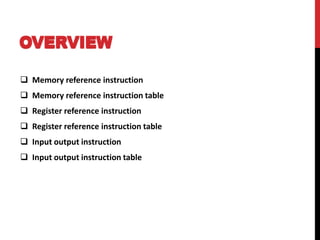
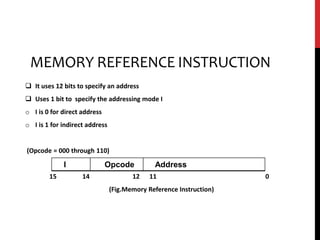
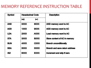
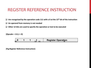
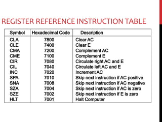
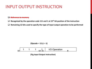
Computer instruction set
OVERVIEW
 Memory reference instruction
 Memory reference instruction table
 Register reference instruction
 Register reference instruction table
 Input output instruction
 Input output instruction table
MEMORY REFERENCE INSTRUCTION
 It uses 12 bits to specify an address
 Uses 1 bit to specify the addressing mode I
o I is 0 for direct address
o I is 1 for indirect address
(Opcode = 000 through 110)
15 14 12 11 0
(Fig.Memory Reference Instruction)
I Opcode Address
MEMORY REFERENCE INSTRUCTION TABLE
REGISTER REFERENCE INSTRUCTION
 Are recognized by the operation code 111 with a 0 at the 15th bit of the instruction
 An operand from memory is not needed
 Other 12 bits are used to specify the operation or test to be executed
(Opcode = 111,I = 0)
15 12 11 0
(Fig.Register Reference Instruction)
0 1 1 1 Register Operation
REGISTER REFERENCE INSTRUCTION TABLE
INPUT OUTPUT INSTRUCTION
 Reference to memory
 Recognized by the operation code 111 and 1 at 15th bit position of the instruction
 Remaining 12 bits used to specify the type of input output operation to be performed
(Opcode = 111,I = 1)
15 12 11 0
(Fig.Input Output Instruction)
1 1 1 1 I/O Operation
I/O INSTRUCTION TABLE
Symbol Hexadecimal Code Description
INT
OUT
SKI
SKO
ION
IOF
F800
F400
F200
F100
F080
F040
Input Character to AC
Output Character from AC
Skip on input flag
Skip on output flag
Interrupt on
Interrupt off
CONCLUSION
Instructions are used for various purposes by computer- each
instruction having its own individual working . . .
Thank you . . .

Computer instruction set

  • 1.
  • 2.
    OVERVIEW  Memory referenceinstruction  Memory reference instruction table  Register reference instruction  Register reference instruction table  Input output instruction  Input output instruction table
  • 3.
    MEMORY REFERENCE INSTRUCTION It uses 12 bits to specify an address  Uses 1 bit to specify the addressing mode I o I is 0 for direct address o I is 1 for indirect address (Opcode = 000 through 110) 15 14 12 11 0 (Fig.Memory Reference Instruction) I Opcode Address
  • 4.
  • 5.
    REGISTER REFERENCE INSTRUCTION Are recognized by the operation code 111 with a 0 at the 15th bit of the instruction  An operand from memory is not needed  Other 12 bits are used to specify the operation or test to be executed (Opcode = 111,I = 0) 15 12 11 0 (Fig.Register Reference Instruction) 0 1 1 1 Register Operation
  • 6.
  • 7.
    INPUT OUTPUT INSTRUCTION Reference to memory  Recognized by the operation code 111 and 1 at 15th bit position of the instruction  Remaining 12 bits used to specify the type of input output operation to be performed (Opcode = 111,I = 1) 15 12 11 0 (Fig.Input Output Instruction) 1 1 1 1 I/O Operation
  • 8.
    I/O INSTRUCTION TABLE SymbolHexadecimal Code Description INT OUT SKI SKO ION IOF F800 F400 F200 F100 F080 F040 Input Character to AC Output Character from AC Skip on input flag Skip on output flag Interrupt on Interrupt off
  • 9.
    CONCLUSION Instructions are usedfor various purposes by computer- each instruction having its own individual working . . .
  • 10.

Editor's Notes

  • #3 A presentation on: Computer instruction set