
Download to read offline

![Graphics Devices – cont
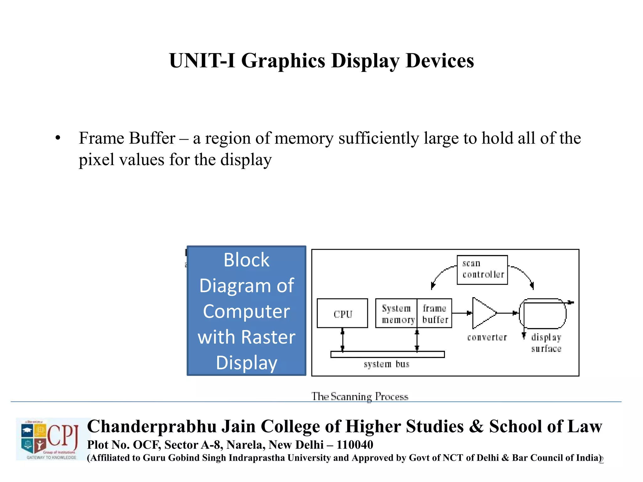
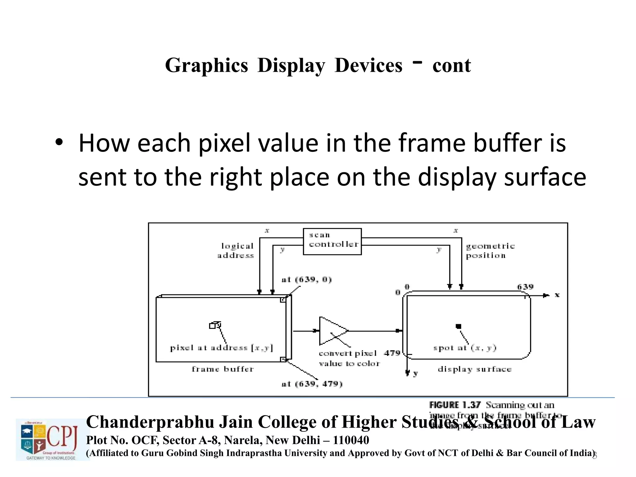
• Each pixel has a 2D address (x,y)
– For each address (x,y) there is a specific memory location
that holds the value of the pixel (I.e. mem[136][252])
– The scan controller sends the logical address (136, 252) to
the frame buffer, which emits the value mem[136][252]
– The value mem[136][252] is converted to a corresponding
intensity or color in the conversion circuit, and that
intensity or color is sent to the proper physical position,
(136, 252), on the display surface
4
Chanderprabhu Jain College of Higher Studies & School of Law
Plot No. OCF, Sector A-8, Narela, New Delhi – 110040
(Affiliated to Guru Gobind Singh Indraprastha University and Approved by Govt of NCT of Delhi & Bar Council of India)](https://image.slidesharecdn.com/bca303-181205071111/75/Computer-Graphics-4-2048.jpg)
![Graphics Devices – cont
• Each pixel has a 2D address (x,y)
– For each address (x,y) there is a specific memory location
that holds the value of the pixel (I.e. mem[136][252])
– The scan controller sends the logical address (136, 252) to
the frame buffer, which emits the value mem[136][252]
– The value mem[136][252] is converted to a corresponding
intensity or color in the conversion circuit, and that
intensity or color is sent to the proper physical position,
(136, 252), on the display surface
5
Chanderprabhu Jain College of Higher Studies & School of Law
Plot No. OCF, Sector A-8, Narela, New Delhi – 110040
(Affiliated to Guru Gobind Singh Indraprastha University and Approved by Govt of NCT of Delhi & Bar Council of India)](https://image.slidesharecdn.com/bca303-181205071111/75/Computer-Graphics-5-2048.jpg)
![Graphics Devices – cont
• Each pixel has a 2D address (x,y)
– For each address (x,y) there is a specific memory location
that holds the value of the pixel (I.e. mem[136][252])
– The scan controller sends the logical address (136, 252) to
the frame buffer, which emits the value mem[136][252]
– The value mem[136][252] is converted to a corresponding
intensity or color in the conversion circuit, and that
intensity or color is sent to the proper physical position,
(136, 252), on the display surface
6
Chanderprabhu Jain College of Higher Studies & School of Law
Plot No. OCF, Sector A-8, Narela, New Delhi – 110040
(Affiliated to Guru Gobind Singh Indraprastha University and Approved by Govt of NCT of Delhi & Bar Council of India)](https://image.slidesharecdn.com/bca303-181205071111/75/Computer-Graphics-6-2048.jpg)
![Graphics Devices – cont
• Each pixel has a 2D address (x,y)
– For each address (x,y) there is a specific memory location
that holds the value of the pixel (I.e. mem[136][252])
– The scan controller sends the logical address (136, 252) to
the frame buffer, which emits the value mem[136][252]
– The value mem[136][252] is converted to a corresponding
intensity or color in the conversion circuit, and that
intensity or color is sent to the proper physical position,
(136, 252), on the display surface
7
Chanderprabhu Jain College of Higher Studies & School of Law
Plot No. OCF, Sector A-8, Narela, New Delhi – 110040
(Affiliated to Guru Gobind Singh Indraprastha University and Approved by Govt of NCT of Delhi & Bar Council of India)](https://image.slidesharecdn.com/bca303-181205071111/75/Computer-Graphics-7-2048.jpg)
![Graphics Devices – cont
• Each pixel has a 2D address (x,y)
– For each address (x,y) there is a specific memory location
that holds the value of the pixel (I.e. mem[136][252])
– The scan controller sends the logical address (136, 252) to
the frame buffer, which emits the value mem[136][252]
– The value mem[136][252] is converted to a corresponding
intensity or color in the conversion circuit, and that
intensity or color is sent to the proper physical position,
(136, 252), on the display surface
8
Chanderprabhu Jain College of Higher Studies & School of Law
Plot No. OCF, Sector A-8, Narela, New Delhi – 110040
(Affiliated to Guru Gobind Singh Indraprastha University and Approved by Govt of NCT of Delhi & Bar Council of India)](https://image.slidesharecdn.com/bca303-181205071111/75/Computer-Graphics-8-2048.jpg)

![Graphics Devices – cont
• Each pixel has a 2D address (x,y)
– For each address (x,y) there is a specific memory location
that holds the value of the pixel (I.e. mem[136][252])
– The scan controller sends the logical address (136, 252) to
the frame buffer, which emits the value mem[136][252]
– The value mem[136][252] is converted to a corresponding
intensity or color in the conversion circuit, and that
intensity or color is sent to the proper physical position,
(136, 252), on the display surface
10
Chanderprabhu Jain College of Higher Studies & School of Law
Plot No. OCF, Sector A-8, Narela, New Delhi – 110040
(Affiliated to Guru Gobind Singh Indraprastha University and Approved by Govt of NCT of Delhi & Bar Council of India)](https://image.slidesharecdn.com/bca303-181205071111/75/Computer-Graphics-10-2048.jpg)


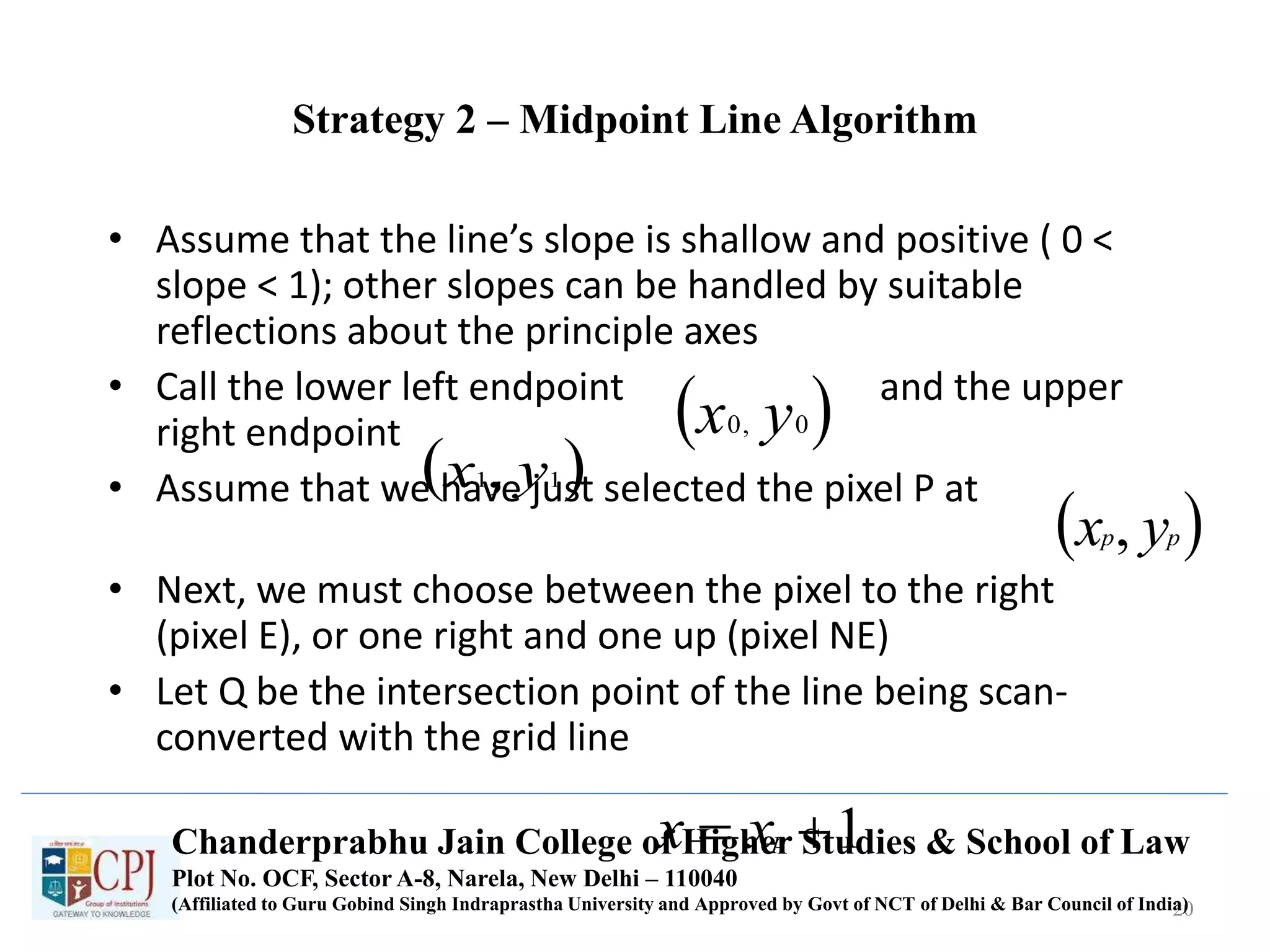
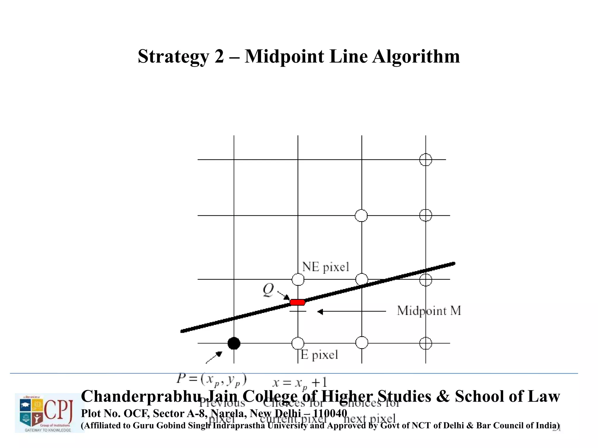
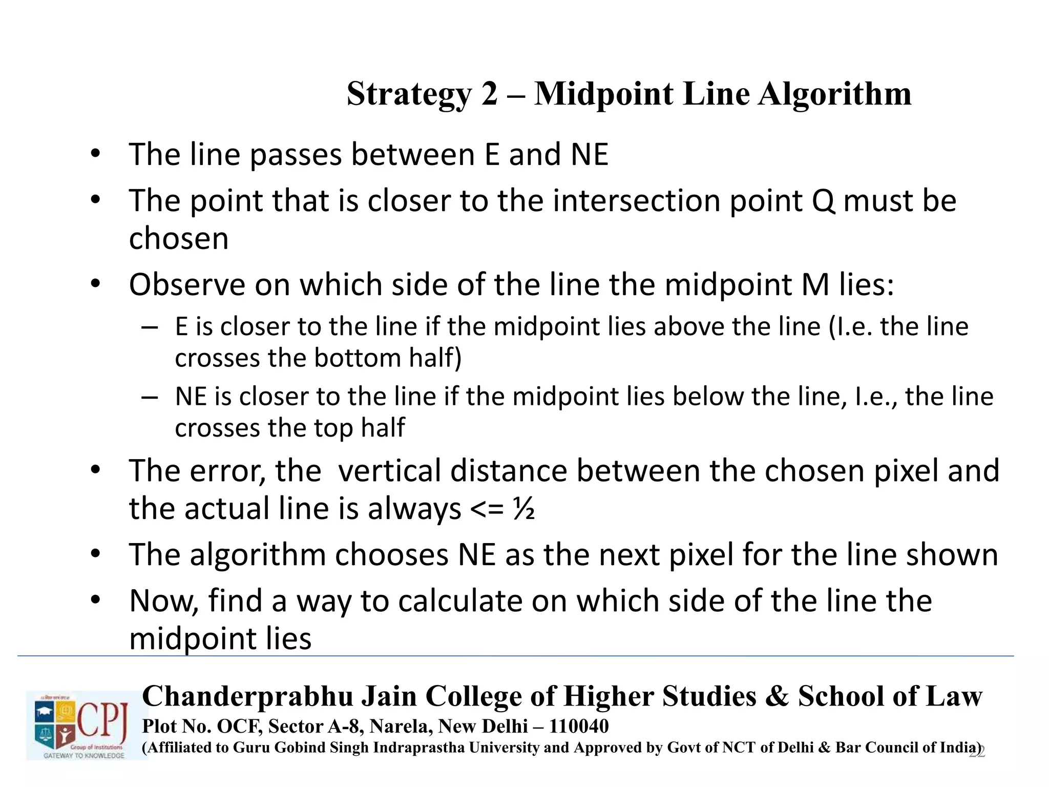


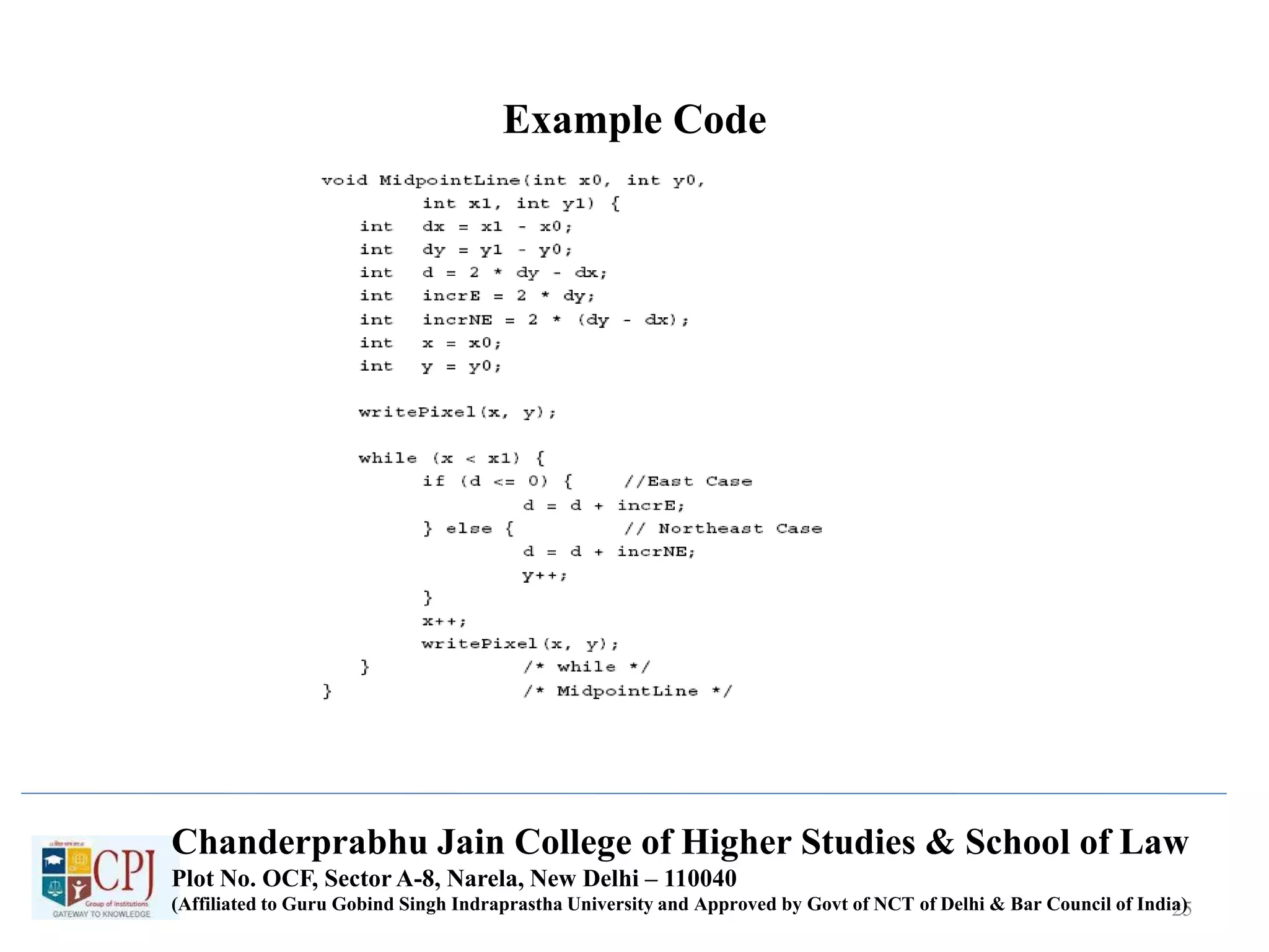


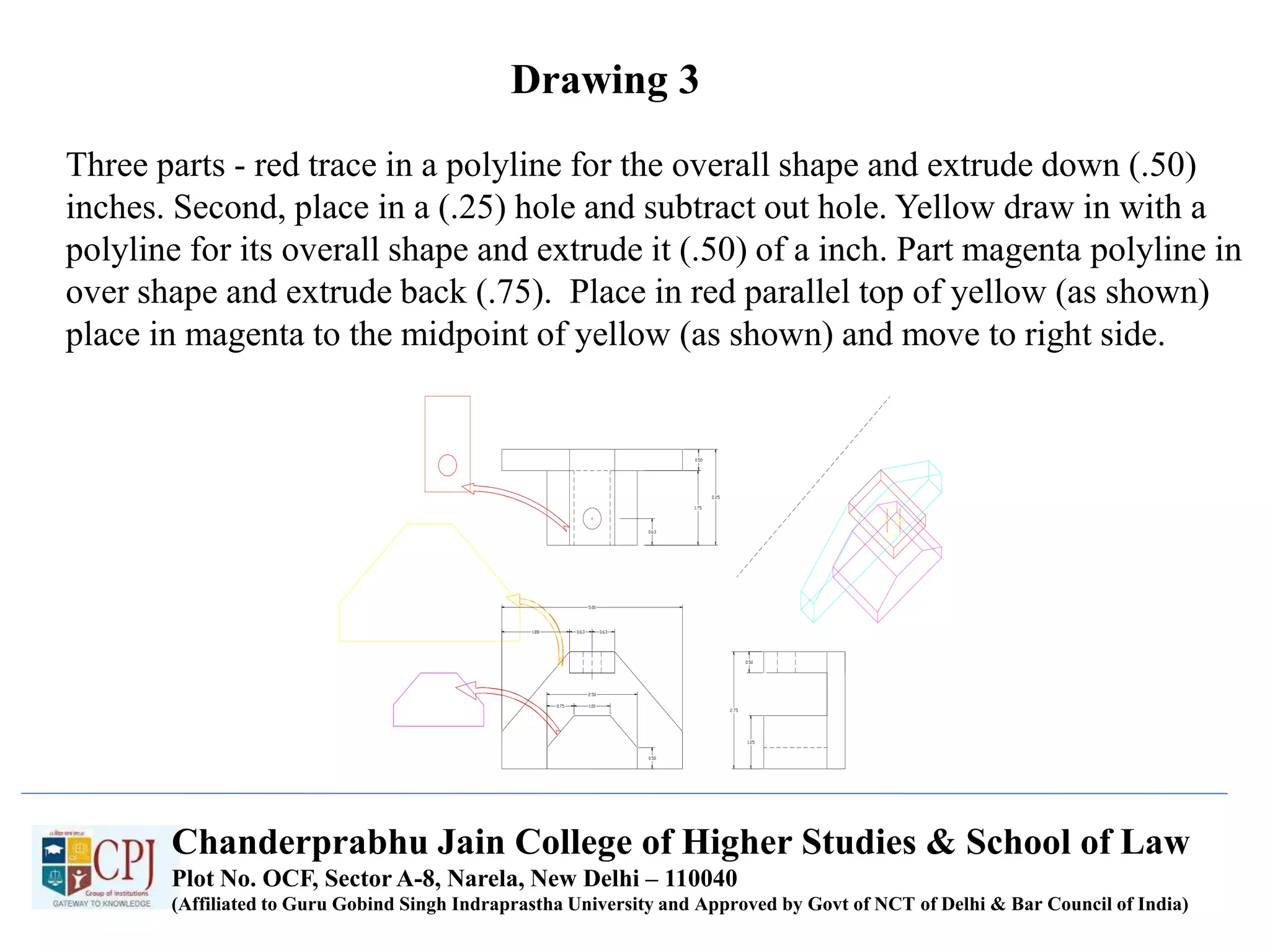
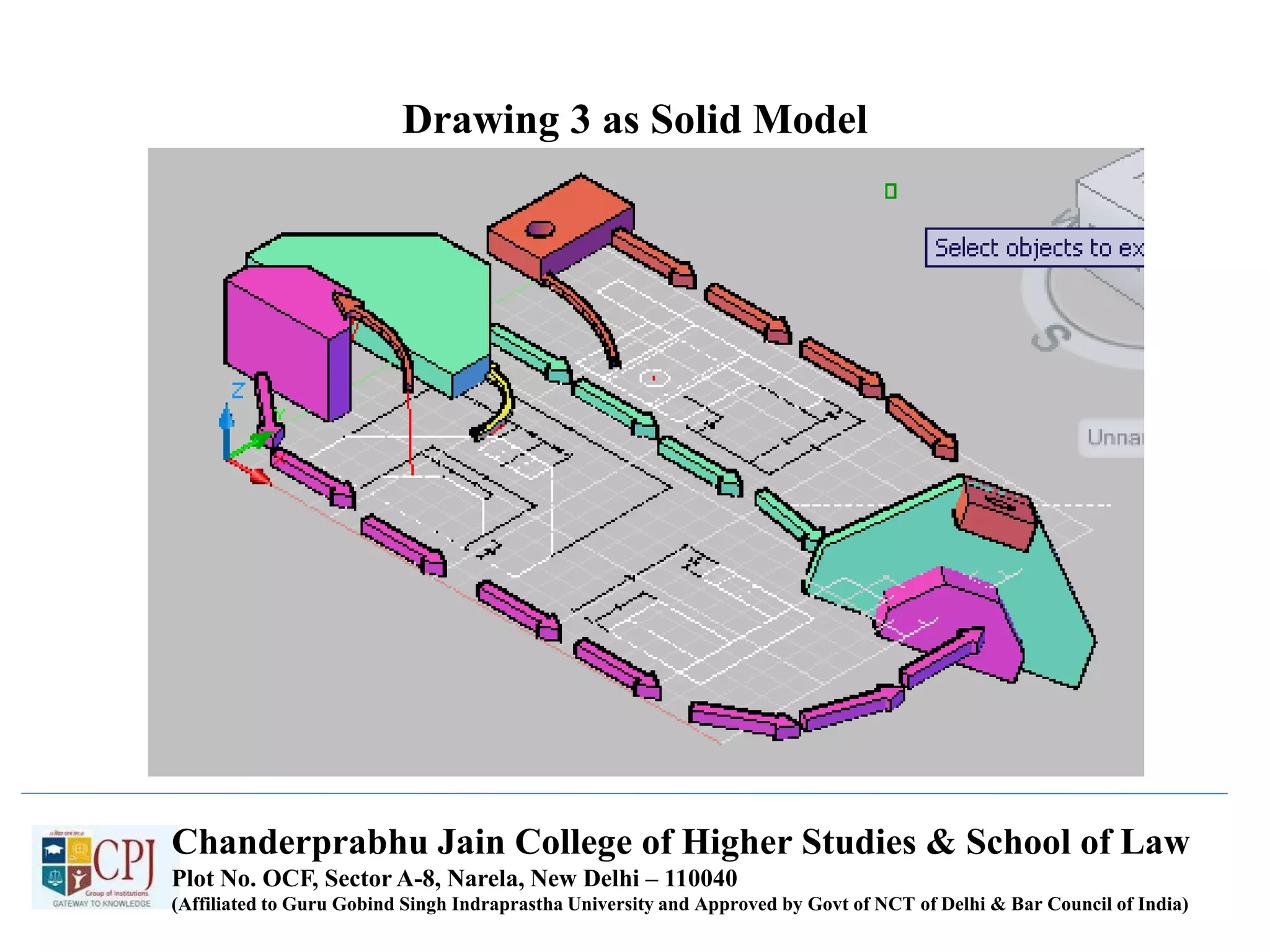

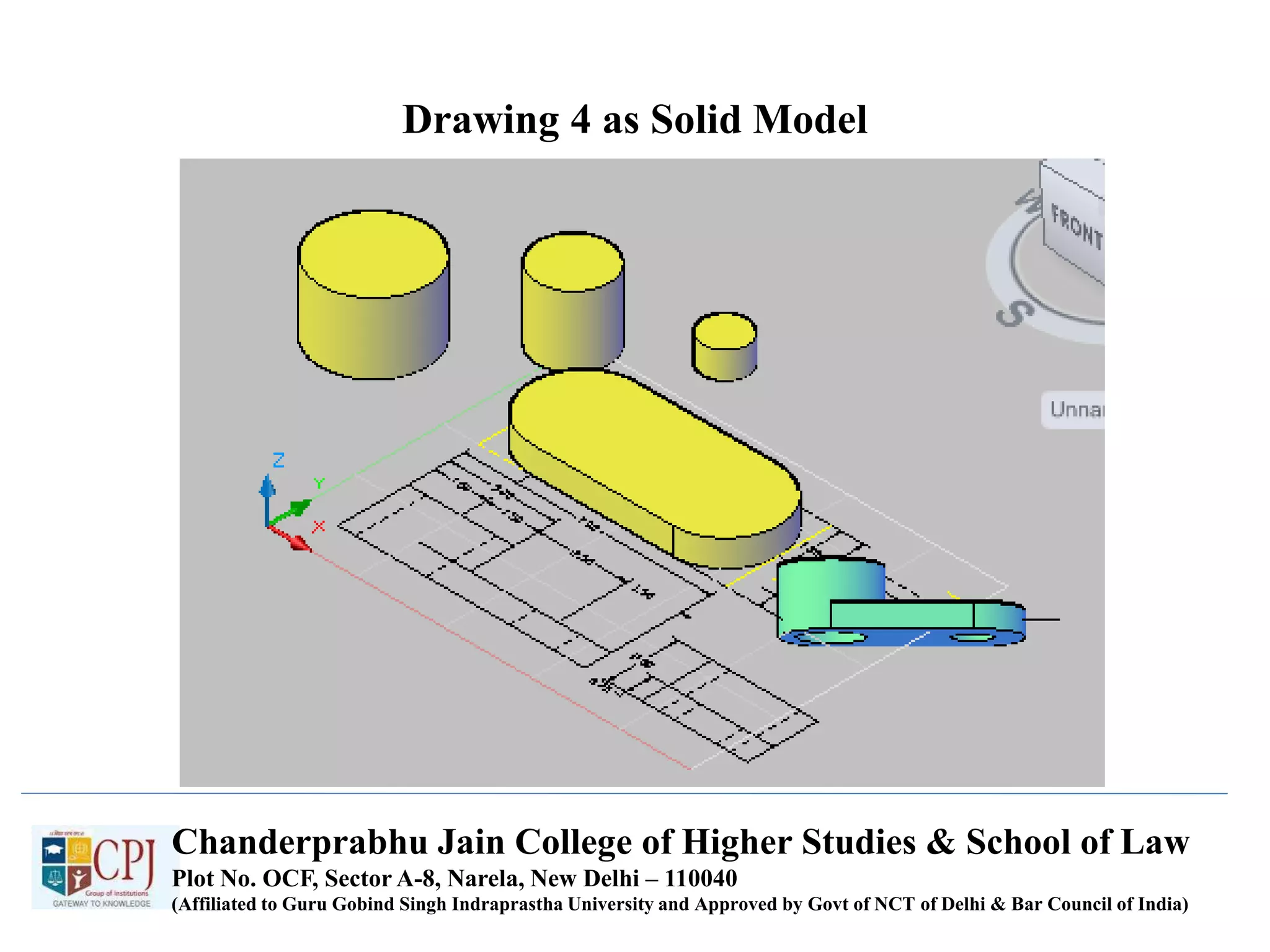


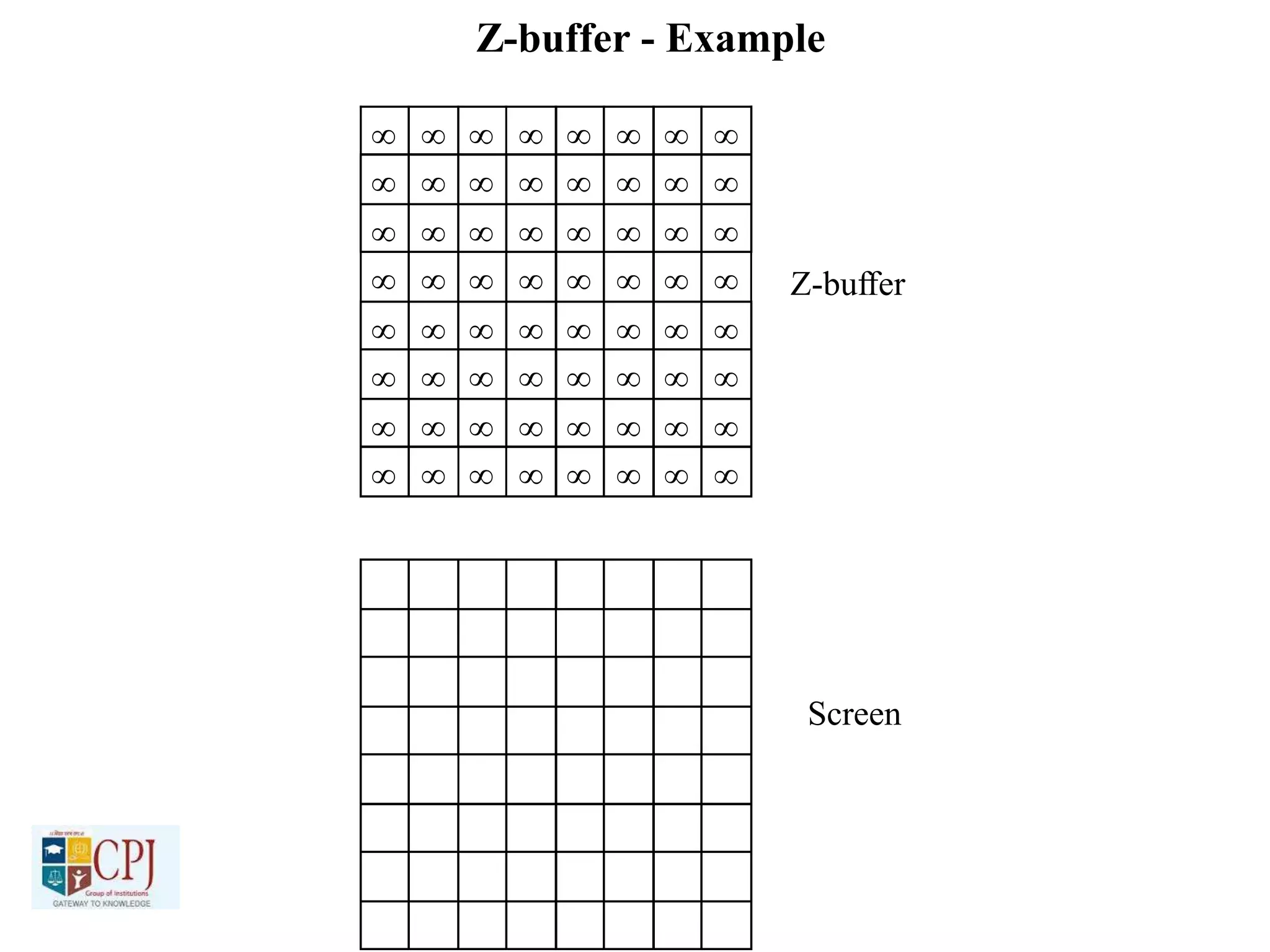
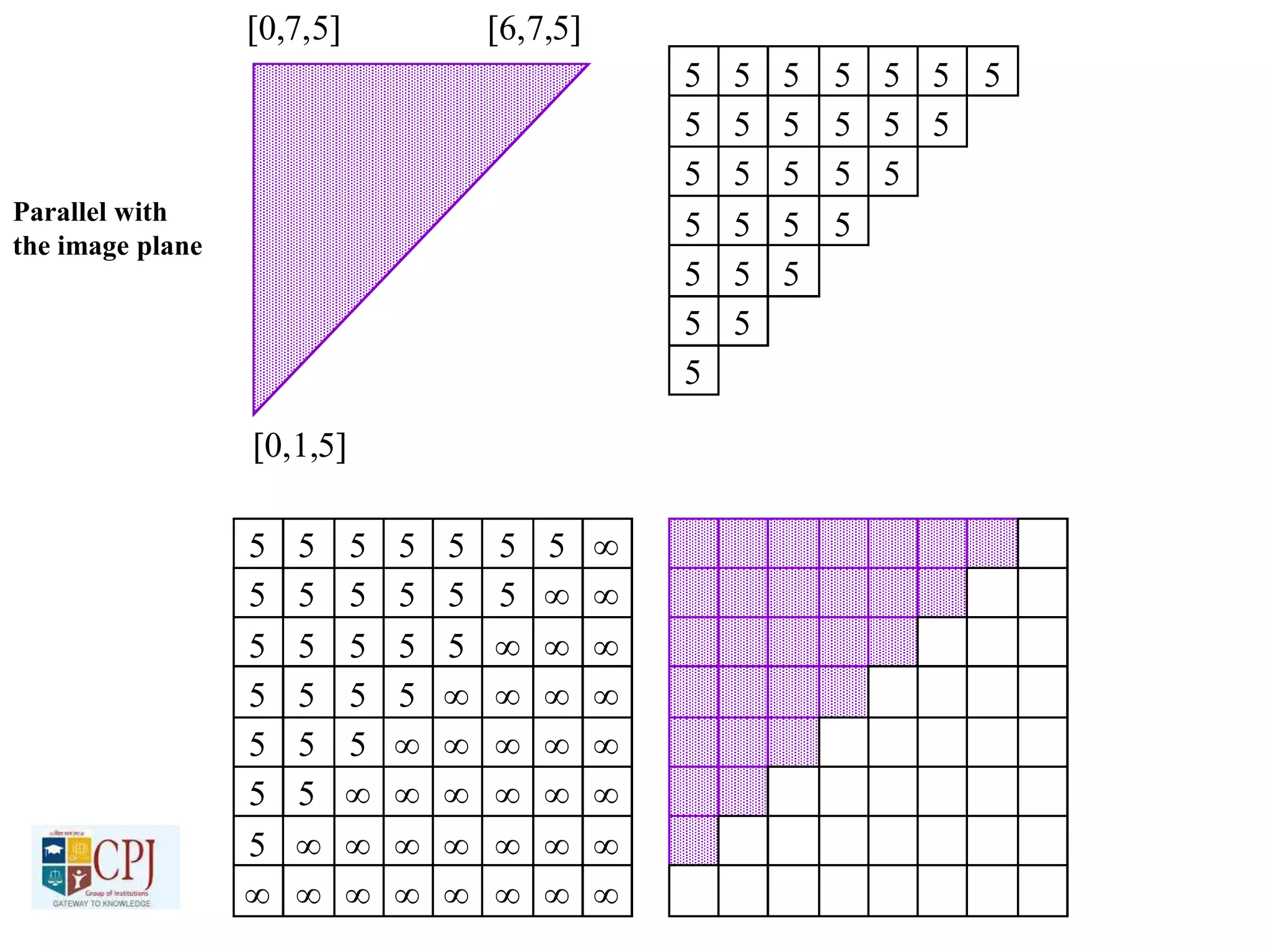
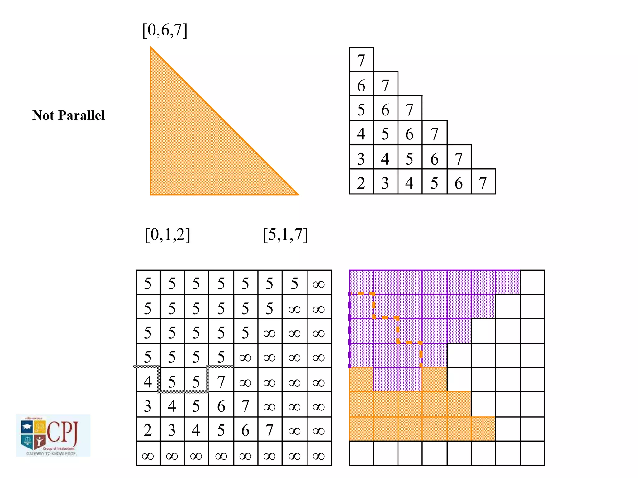
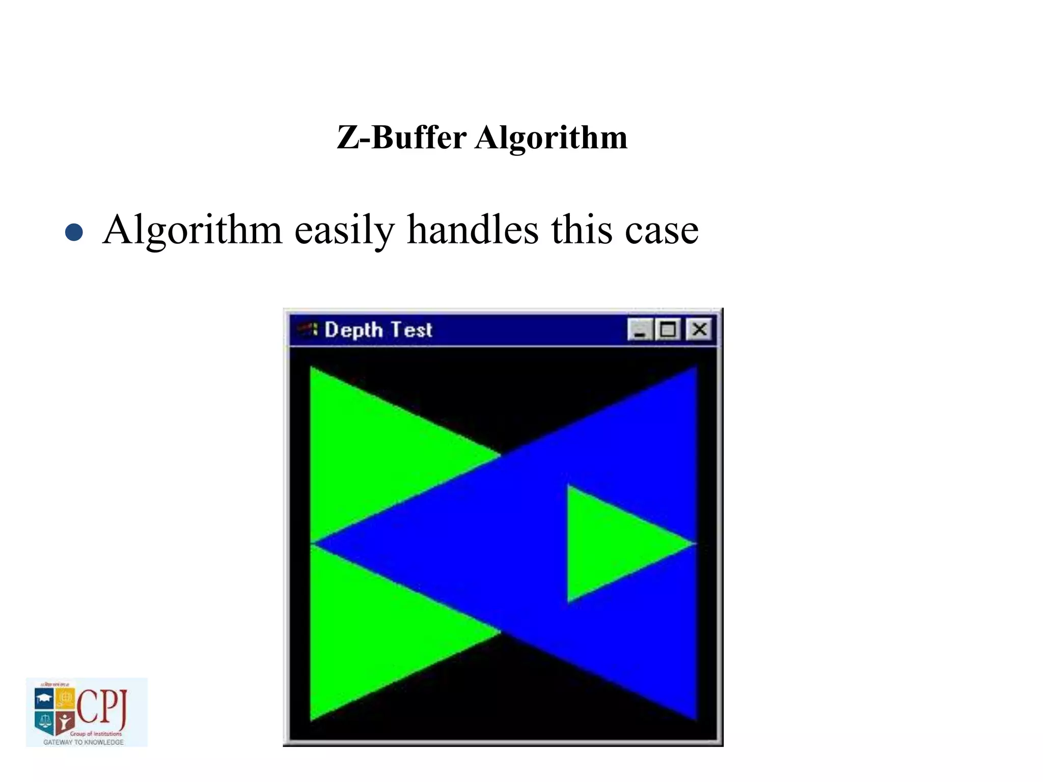
The document discusses graphics display devices and algorithms for scan converting lines in computer graphics. It describes how a frame buffer stores pixel values and how these values are sent to the display surface. It then examines two algorithms for scan converting lines: an incremental algorithm that calculates the next pixel by incrementing the x and y coordinates, and a midpoint line algorithm that determines which of two potential next pixels is closer by calculating on which side of the line the midpoint lies. The midpoint algorithm avoids errors from rounding and representation that can occur in the incremental approach.


![Alternative Dispute Resolution (ADR) [LLB -309]](https://cdn.slidesharecdn.com/ss_thumbnails/pptadr-201112101023-thumbnail.jpg?width=640&height=640&fit=bounds)


![Women and Law [LLB 409 (c)]](https://cdn.slidesharecdn.com/ss_thumbnails/pptwomenandlaw-201107184654-thumbnail.jpg?width=640&height=640&fit=bounds)


