
Recommended
Recommended
More Related Content
What's hot
What's hot (20)
Similar to #Compressed air supply
Similar to #Compressed air supply (20)
More from Nisar Arain
More from Nisar Arain (20)
Recently uploaded
Recently uploaded (20)
#Compressed air supply
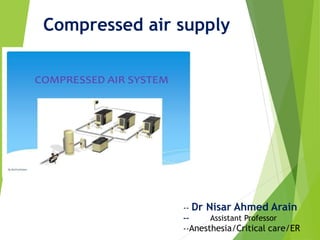
- 1. Compressed air supply -- Dr Nisar Ahmed Arain -- Assistant Professor --Anesthesia/Critical care/ER
- 2. 2 © UNEP 2006 --Training Agenda and Compressor --Introduction --Types of Compressors --Assesment of Compressors and compressed air system --Energy efficiency opportunities
- 3. Compressors:5to> 50,000hp 70– 90%ofcompressedairislost --INTRODUCTION --Significant Inefficiencies
- 4. INTRODUCTION --BENEFITS OF MANAGED SYSTEM --Electricity Savings: 20—50% --Maintenance reduced --Downtime decreased --Production increased and --Product quality improved
- 5. Introduction Main Components in Compressed Air System --Intake Air Filters --Inter Stage --Coolers After Coolers --Coolers --Air Dryers --Moisture drain traps --Receivers
- 6. -Training Agenda Compressor --Introduction --Types of Compressors --Assesment of Compressors and compressed air systems --Energy efficiency opportunities
- 7. Typeof compressor Positive displacement Dynamic Reciprocating Rotary Centrifugal Axial -Types of Compressors -Two Basic Compressor Types
- 8. -Types of Compressors -Reciprocating Compressor --Used for air and refrigerant Compression --Works like a bicycle Pump: Cylinder volume reduces while pressure increases with pulsating output --Many configurations are available --Single acting when using one side of the piston and double acting when using both sides
- 9. -Types of Compressors -ROTATORY COMPRESSORS --Rotators instead of Pistons: continuous discharge --Benefits of Low cost, Compact, low weight, easy to maintain sizes between 30 to 200 hp --TYPES --Lobe Compressor --Screw compressor --Rotatory Vane/Slide Vane
- 10. -Types of Compressors -Centrifugal Compressor --Rotating impeller transfers energy to move air continuous duty --Designed oil free High Volume applications >12,000 cfm
- 11. - Types of Compressors -Comparison of Compressors --Efficiency at full, partial and no load --Noise level --Size --Oil Carry-over --Vibration --Maintenance --Capacity --Pressure
- 12. -Training Agenda Compressor --Introduction --Types of Compressors --Assesment of Compressors and compressed air system --Energy efficiency opportunity
- 13. --Assesment of Compressors --Capacity of a Compressor --Capacity:-Full rated volume of flow of compressed gas --Actual Flow Rate:-Free air delivery(FAD) --FAD:- reduces by ageing, Poor Maintenance and Fouled heat exchanger and altitude --Energy Loss:-Percentage deviation of FAD Capacity
- 14. --Assesment of Compressors --Simple Capacity Assesment Method --Isolate compressor and receiver and close receiver outlet --Empty the receiver and the pipeline from water --Start the compressor and activate the stop watch --Note time taken to attain the normal operational pressure P2(In the receiver)from initial pressure P1 Calculate the capacity FAD --P2=Final Pressure after filling (Kg/cm2a) --P1=Initial Pressure(Kg/cm2a) after bleeding) --P0=Atmospheric pressure (Kg/cm2a) --V=Storage volume in m3 which includes receiver, after cooler and delivery piping --T=Time taken to build up pressure to P2 in minutes
- 15. --Assesment of Compressors --Compressor Efficiency --Most practical specific power consumption (KW/Volume flow rate) --Other methods a-Isothermia-1 b-Volumatric c-Adiabatic d-Mechenical
- 16. -Assesment of Compressors -Compressor Efficiency -Isothermal efficiency --Isothermal efficiency=Actual measured input power per Isothermal power --Isothermal power(KW)=P1 x Q1 x logger / 36.7-P1= Absolute intake pressure Kg Per cm2 --Q1=Free air delivered m3 per hr --r=Pressure ratio P2/P1s
- 17. -Assesment of Compressors -Compressor Efficiency -Volumetric efficiency --Volumetric efficiency=Free air delivered/compressor displacement --Compressor displacement=ΠxD2/4xL xS xχ x n-D=Cylinderbore,meterL=Cylinderbore, meterL=Cylinderstroke,meterS=compressor speedrpmX =1forsingleactingand2for doubleactingcylindersn=No.ofcylinders
- 18. -Assesment of Compressors -Leaks --consequences --Energy waste: 20 – 30% of output --Drop in the system pressure --shorter equipment life --Common leakage areas --Couplings, hoses, tubes, fittings --Pressure regulators --Open condensate traps, shut off valve --Pipe joints, disconnects, thread sealants
- 19. -Assesment of Compressors -Leak Qualification Method -Total Leakage Calculation --Leakage (%) = [(Tx100)/(T + t)] --T=On load time(minutes) t=off load time (Minutes) --well maintained system: less than 10% leakages
- 20. -Assesment of Compressors -Quantifying leaks on the shop floor --Shut off compressed air operated equipment's run compressor to charge the system to set pressure of operation --Note the time taken for “Load” and “Unload” cycles calculate quantity of leakage (previous slide) If Q is actual free air supplied during trial (m3/min) then system leakage (m3/minute) = Q X T (T + t)
- 21. ---Compressor capacity (m3/minute) = 35 ---Cut in pressure, kg/cm2 = 6.8 ---Cut out pressure, kg/cm2 = 7.5 ---Load kW drawn = 188 kW ---Unload kW drawn = 54 kW ---Average ‘Load’ time =1.5 min ---Average ‘Unload’ time -Assesment of Compressors --EXAMPLE
- 22. -Raining Agenda: Compressor --Introduction --Types of compressors --Assesment of compressors and compressed air systems --Energy efficiency opportunities
- 23. -Energy Efficiency Opportunities 1-Location significant influence on energy use 2-Elevation Higher altitude = lower volumetric efficiency
- 24. -Energy Efficiency Opportunity 3. Air Intake --Keep intake air free from contaminants, dust or moist Keep intake air temperature low --Every 4oC rise in inlet air Temperature = 1% higher energy consumption --Keep ambient temperature low when an intake air filter is located at the compressor
- 25. -Energy Efficiency Opportunities 4. Pressure Drops in air Filter --Install filter in cool location or draw air from cool places --Keep pressure drop across intake air filter to a minimum --Every 250 mm WC pressure drop = 2% higher energy consumption
- 26. -Energy Efficiency Opportunities -5. Use Inter and After coolers --Inlet air temperature rises at each stage of multistage machine --Inter coolers: heat exchangers that remove heat between stages --After coolers: reduce air temperature after final stage --Use water at low temperature: reduce power
- 27. -Energy Efficiency Opportunities 6.Pressure Settings -Higher Pressure a-More power by compressors b-Lower volumetric efficiency -Operating above operating pressures a-Waste of energy b-Excessive wear
- 28. Energy Efficiency Opportunities 6.Pressure setting cont. --a-Reducing delivery pressure operating a compressor at 120 PSIG instead of 100 PSIG: 10% less energy and reduced leakage rate --b-Compressor modulation by optimum pressure settings, Applicable when different compressors connected Segregating high/Low pressure requirements Pressure reducing valves no longer needed
- 29. -Energy Efficiency Opportunities 6-Pressure Settings cont. --Design for minimum pressure drop in the distribution line --Pressure drop: reduction in air pressure from the compressor discharge to the point of use --Pressure drop less then 10% --Pressure drop caused by a-corrosion b-Inadequate sized piping couplings hoses c-checked filter elements inadequate sized
- 30. 3 0 © UNEP 2006 -- Energy Efficiency Opportunities --6-Pressure settings cont. --Design for minimum pressure drop in the distribution line --Different pipe size --Typical pressure drop in compressed air line
- 31. -Energy Efficiency Opportunities 7-Minimizing Leakage --Use ultrasonic acoustic detector tighten joints and connections replace faulty equipment 8-Condensate Removal --Condensate formed as after cooler reduces discharge air temperature --Install condensate separator trap to remove condensate
- 32. -- Energy Efficiency Opportunities 9-Controlled Usage --Do not use for low pressure applications agitation, combustion air, Pneumatic conveying use blowers instead 10-Compressor Controls --Automatically terns off compressor when not needed
- 33. Energy Efficiency Opportunities 9-Maintainence Practices --Lubrication:- checked regularly --Air Filters:-Replaced regularly --Condensate Traps:-Ensure drainage --Air dryers:-Inspect and replace filters
- 34. THANK YOU