SlideShare a Scribd company logo
1 of 95
PRESENTED BY
DR. PREETI RASTOGI
MDS
DEPT. CONSERVATIVE
DENTISTRY AND
ENDODONTICS
“SIMPLICITIES ARE ENORMOUSLY COMPLEX” – Richard O Moore
OUTLINES
 DEFINTION
 CLASSIFICATION OF
CORONAL TOOTH
DESTRUCTION
 EXTRA RETENTIVE
DEVICES
 RATIONALE TO USE PINS
 INDICATIONS FOR PINS
 ADVANTAGE
 DISADVANTAGE
 CLASSIFICATIONS OF PINS
 DIRECT PIN
 PIN MATERIAL
 PRINCIPLE OF PIN
PLACEMENT
 FACTORS AFFECTING
RETENTION OF PIN IN
TOOTH STRUCTURE
 FACTORS AFFECTING
RETENTION OF PIN IN
RESTORATIVE MATERIAL
 COMPLICATION DURING
PIN PLACEMENT
 FAILURE OF PIN RETAINED
RESTORATION
 EFFECT OF PIN ON PULP
 AMAGAPIN
 PIN RETAINED CAST
RESTORATION
COMPLEX AMALGAM RESTORATION 2
The operative
dentist is
confronted with
restoration of
extensively
damaged teeth in
routine. Many a
times, the damage,
which may be
because of caries,
trauma or previous
restorations,
involves half or
more than half of
the tooth structure.
The remaining
tooth structure is
not sufficient to
retain the
restoration and
require
modification of
classic preparation
design by
incorporation of
various retentive
means.
Such restorations,
which require extra
retentive device for
their retention, are
labeled as
‘Complex
restorations'.
COMPLEX AMALGAM RESTORATION 3
 According to Sturdevant –
◦ Complex restorations are used to replace any missing structure of
teeth that have fractured, have severe caries involvement, or have
existing restorative material.
 These restorations usually involve the replacement of
one or more missing cusps and require additional means
of retention.
COMPLEX AMALGAM RESTORATION 4
HISTORY
In 1897, Arthur described the use of anchor
screws in the dentin to retain restorations.
The pin amalgam restoration became widely
accepted after Dr. Miles Markley popularized
it in 1958.
In 1969, Moffa et.al reported on the retentive
properties of three different pin designs in
dentin and amalgam.
COMPLEX AMALGAM RESTORATION 5
 Location, as well as extent of coronal destruction, plays an important role in selection
of material and design of cavity preparation employed in restoration of tooth.
COMPLEX AMALGAM RESTORATION
6
Treatment options
Minimal Moderate Severe
Central (which occurs
in the central portion
of the tooth )
•Amalgam
•Composite
•Bonded amalgam
•Sandwich
technique
•Amalgam core+ crown
Peripheral (which
occurs on the axial
surfaces of the teeth )
•Amalgam
•Composite
•Pin Amalgam
•Pin Composite
•Cast restoration
•Crown
•Full crown
Combined (which
incorporates
destruction in both
areas )
•Amalgam •Pin amalgam
•Onlay
•Amalgam core+ crown
•Cast pin restoration
To compensate the lost tooth structure, one or
more than one retentive device is utilized
The routinely used retentive devices are:
i. Slots
ii. Grooves/Locks
iii. Pins
COMPLEX AMALGAM RESTORATION 7
 Slots are given to increase the surface area for the restoration.
 A 0.75-1.0 mm deep and 1.0- 3.0 mm wide cut is given on the pulpal and/
or cervical wall.
 This rectangular depression in these walls increases the bulk for the
restoration, and also increases the area for bonding.
COMPLEX AMALGAM RESTORATION 8
Dentinal slots are prepared approximately 1 mm deep and 0.5 to 1 mm
inside the Dentinoenamel junction (DEJ)
 Multiple grooves can also be given for enhanced resistance. Care should be taken to place
the grooves in one plane. More than one groove per wall is rarely indicated and if necessary,
can be given keeping proper parallelism and dentin around each groove.
COMPLEX AMALGAM RESTORATION
9
A retention lock is a prepared groove
whose length is in a vertical plane and
which is in dentin.
GROOVES LOCKS
Grooves are given in indirect restorations Locks are given in direct restorations
Groove extends upto the cavosurface
margin (from cervical to cavosurface)
Lock extends upto the pulpal wall (from
cervical to pulpal)
Groove maintain the parallelism of walls Lock converge occlusally
The grooves/locks are given at axiobuccal and axio-lingual line angle, inside dentine-
enamel junction, putting more pressure on buccal and lingual walls rather than at the axial
walls.
Placement of retention locks. A, Position of No.
169L bur to prepare the retention lock. B, Lock
prepared with No. 14 bur.
• A pin retained restoration is defined as any restoration
requiring the placement of one or more pins in dentin to
provide adequate resistance and retention form.
• [Sturdevant]
• A pin is an extension of a restoration into a prepared hole or a
metal rod secured in a hole drilled in dentin for the purpose of
retaining a restoration in or on the tooth.
• [Atlas of operative dentistry]
• A pin is small rod that fits into a channel drilled into dentin
away from the pulp space. It is also referred as a dentinal pin
or a parapulpal pin.
• [Richard J, Shillinburg D.C.N.A Vol 37(3)
1993]
COMPLEX AMALGAM RESTORATION 10
In 1958, Dr Miles Markley introduced stainless steel pins to provide retention and
resistance in extensively decayed teeth.
Pins help to support the restorative materials and
resist their dislodgement in severely damaged and
weakened teeth.
Unlike restoration with conventional cavity
preparation pin retained restoration provide
efficient and adequate retention with the least
sacrifice of healthy tooth structure.
With the use of pins, cavity preparation can also be
limited to only damaged surfaces thereby
preserving esthetics and contours.
Various studies concluded that stainless steel pins in
amalgam did not actually strengthen it. Hence, the
use of pins is restricted for extra retentive purposes.
Pins are auxiliary aids of retention and are used
only after primary retentive features like
establishment of parallel walls, boxes and grooves
as are not sufficient to provide the desired amount
of retention.
COMPLEX AMALGAM RESTORATION 11
1. Pins are indicated as auxiliary aids of retention in badly broken down or
mutilated teeth, large class II, class III, class IV and class V cavity
preparations.
2. In teeth with guarded prognosis, i.e. in endodontically and
periodontically involved teeth, pin retained restorations are more useful
than comparatively expensive treatments.
3. Pins may be used in foundations for full or partial metal or metal
ceramic restorations.
4. When cost is a major factor for the patient, pin retained restorations may
be a cheaper alternative in complex situations.
5. For Geriatric and debilitated patients, pin amalgams are the preferred
choice over cast restorations.
COMPLEX AMALGAM RESTORATION 12
1)If the patient has significant occlusal problems,
2) If the tooth cannot be restored properly with
direct restoration because of anatomic or
functional considerations (or both).
3)If the area to be restored has esthetic
importance for the patient.
COMPLEX AMALGAM RESTORATION 13
 Conservation of tooth material: More conservative
than tooth preparation for cast restoration.
 Resistance and retention form: Use of pin and slots
increases the resistance and retention of the
restoration
 Number of appointments: Relatively less time
consuming than cast restorations, which require
multiple appointments.
 Cost factor: Comparatively less expensive than cast
restorations for salvaging badly broken down teeth.
COMPLEX AMALGAM RESTORATION 14
 Dentin fracture: Use of pins in teeth where less dentin is present,
may result in stresses in dentin in form of craze lines or cracks
 Strength of amalgam: Compressive strength is not increased by use
of pins, but there is decrease in tensile and transverse strength of
amalgam
 Perforations: Using bur or pin in wrong direction can cause pulpal
exposure or perforation of external tooth surface.
 Microleakage: If pin ends appear on or near to the surface of the
restoration, it may result in microleakage around the pins.
 Tooth anatomy: Sometimes, it is difficult to achieve optimal
contours and occlusal contacts with these restorations.
COMPLEX AMALGAM RESTORATION 15
Pins can be
classified as:
Direct pins/non-
parallel pins
Cemented pins
••Friction locked
pins
Self-threading
pins (most
popular)
Indirect pins/
parallel pins
Cast gold pins
Wrought
precious metal
pins
COMPLEX AMALGAM RESTORATION 16
INDIRECT PINS
 Are slightly undersized to their pinholes and are the integral part of the
cast restoration.
 Are known as parallel pins as the method necessitates placement of
pins parallel to each other as well as parallel to the path of insertion of
the restoration.
 Retention offered is less as compared to non parallel pins.
 Two types of pins are used:
Cast gold pins &
Wrought precious metal pins
COMPLEX AMALGAM RESTORATION 17
CAST GOLD PINS
 Have relatively smooth surface.
 Restorations using these pins are fabricated by keeping the nylon
bristles or plastic pins in the pinholes on which the rest of the
restoration is built in the conventional form with blue inlay wax.
 The whole assembly in then invested and casted with pins jamming
an inherent part of the cast restoration.
COMPLEX AMALGAM RESTORATION 18
WROUGHT PRECIOUS METAL
PINS
 They have surfaces that is deformed or roughed by means of threaded or
Knurled patterns.
 These pins are alloys of gold, platinum palladium or platinum indium.
 The pins are placed in the pinholes and are induced in the wax pattern.
 Their high melting point and tarnish resistance enable them to be
incorporated into the final gold casting.
 These are 20-30% more retentive than smooth cast pins.
COMPLEX AMALGAM RESTORATION 19
 Direct pins are usually made of stainless steel, and inserted into dentin followed by the
placement of a restorative material like silver amalgam, resin or cement directly over
them.
 Other materials of which the pins can be made of are silver, titanium, stainless steel
with gold plating, etc.
 These have also been referred to as the non-parallel pins since they can be inserted
directly into the tooth structure and hence need not be parallel.
 Category of pins includes:
COMPLEX AMALGAM RESTORATION 20
Three types of pins. A, Cemented. B, Friction-locked. C, Self-
threading
 Markley introduced cemented pins in 1950s to achieve
retention in a large silver amalgam restoration.
 In this technique, the pins are 0.0013 " - 0.0023" smaller
than their pin channels and the difference in diameter
provides space for the cementing medium.
 Cemented pins are indicated in cases where:
o Least crazing and stresses are desired in the remaining
tooth structure, e.g. endodontically treated teeth,
o Bulk of dentin to accommodate the pin is limited,
o There is no other choice but to place the pin near the
dentino-enamel junction and
o Dentin has lost its elasticity because of sclerosis or
dehydration.
o It is the preferred technique for class IV preparations.
COMPLEX AMALGAM RESTORATION 21
T
E
C
H
N
I
Q
U
E
The pin is held with forceps and coated with cement.
Pin hole is dried with endodontic paper points and coated with cement with help of
endodontic file, explorer or lentulospiral.
The length should be such that after seating the pin into the pin channel completely, the pin
extends not more than 2-3 mm above the base.
If the pin channel is directly accessible, cut the pin wire extra-orally to the desired length
with a wire cutter or a Dial-A-Pin cutter. Cutting a pin after cementation may break the
cement bond and dislodge it.
Pinholes extending 2 - 4 mm into dentin are prepared using twist drills.
Commonly utilizes pins in the form of stainless steel wires, which are serrated or threaded
and cut to the required length.
COMPLEX AMALGAM RESTORATION 22
MODIFIED TECHNIQUE
 This technique was later modified using threaded stainless steel
pins of the same size as the twist drill.
 Most commonly used size is the 0.027".
 The advantages offered by this technique are:
◦ Close contact between the pin and channel
◦ Increased lateral stability.
 The pin is cut and modified by creating a longitudinal facet with
a carborundum disc.
 This facet serves as a vent and is necessary to allow escape of
excess cement especially when the pin and the channel diameters
closely match.
COMPLEX AMALGAM RESTORATION 23
 Cemented pins are approximately 0.001"-0.002" smaller than their pinholes
and hence are more likely to be seated to the full depth of the hole.
 Since they are passively retained in the dentin, they virtually place no stress
on the surrounding dentin during or after placement.
 Because the cement seals the interface between the pin and the tooth,
chances of microleakage are reduced.
 These can be cut or bent to their final configuration before fixing them in
the pin holes.
COMPLEX AMALGAM RESTORATION 24
 They offer less retention compared to the friction
locked and threaded pins.
 It is often difficult to insert cement into the pinhole
and later locate the hole after cement has been
introduced.
 At times, a poorly cemented pin is easily dislodged
when the filling material is being inserted.
 Greater time is required for the mixing and hardening
of the cement.
COMPLEX AMALGAM RESTORATION 25
 Goldstein introduced the friction locked pins to
improve the disadvantages of cemented pins.
 These pins are 0.001" larger than their pin
channels and hence utilize the elasticity of dentin
for retaining the tapped pins in a vise like grip.
 These pins are indicated in
o Teeth that are vital and periodontally sound,
o Where direct access is possible so that the tapping
force can be applied parallel to the long axis of the
pin.
o When sufficient amount of dentin is available to
surround the pin and in no way should they be
placed closer than 1.5 mm to the dentino enamel
junction.
COMPLEX AMALGAM RESTORATION 26
T
E
C
H
N
I
Q
U
E The pin is felt to reach the bottom of the pinhole by sense of touch and sound.
Forces are applied until the established mark on the pin reaches the cavity floor.
A mallet is then used to apply force parallel to the axis of the pin.
The pin is inserted into a pin setter and carried to pin hole.
The depth to which pin channel has been drilled is marked on the pin.
Desired length of the pin is cut extraorally.
A self-centering spiral drill mounted in a low speed handpiece is used to prepare the
pin channel in dentin to a depth of 2-3 mm, 1.5 mm inside the DEJ
COMPLEX AMALGAM RESTORATION 27
 Cement is not required so one does not have to wait for the cement to set
and other related problems.
 Pins acquire stability from the moment they are inserted.
 Better retention than the cemented pins.
COMPLEX AMALGAM RESTORATION 28
 The length of the pin is judged by trial and error. It cannot be
removed from dentin for cutting to the desired length once inserted.
 Bending or contouring of the pin after it has been inserted into the
pinhole leads to further stresses.
 Driving pins into their respective pinholes generates stresses in
dentin in the form of cracks or craze lines.
 Many a times, the pins do not reach the full depth of the channel
because of gouging, and hence may lose some of their retentive
capacity.
 Microleakage is higher than for cemented pins, if the overlying
restoration leaks.
COMPLEX AMALGAM RESTORATION 29
 Going introduced the use of threaded pins.
 Threaded pins are 0.0015 "-0.002" larger than their pin
channels they are retained by the elasticity of dentin.
 They actively engage the tooth structure through their
threads similar to a screw inserted into a wooden block.
 Threaded pins are most popular amongst the three pin
systems due to their ease and rapidity of insertion, and
maximum retention offered.
 Threaded pins are indicated in:
o Vital teeth and where maximum retention is desired.
o When sufficient amount of dentin is available to
surround the pin.
COMPLEX AMALGAM RESTORATION 30
Four varieties of threaded pins are available
depending on their sizes (in decreasing order of
sizes) as:
Regular - 0.030",
0.031"
Minim - 0.024 "
0.025"
Minikin - 0.019",
0.020"
Minuta - 0.014",
0.015"
COMPLEX AMALGAM RESTORATION
31
Four sizes of the Thread Mate System (TMS) pins.
A, Regular (0.031 inch [0.78 mm]). B, Minim (0.024 inch [0.61 mm]).
C, Minikin (0.019 inch [0.48 mm]). D, Minuta (0.015 inch [0.38 mm]).
The four basic
designs of
threaded pins are:
Standard design
Self shearing
single pin design
Two-in-one
design and
Disposable latch
head design
COMPLEX AMALGAM RESTORATION
32
Five designs of the Thread Mate System
(TMS) pins. A, Standard. B, Self-
shearing. C, Two-in-one. D, Link Series.
E, Link PlusStandard pin
Self-shearing pin
Two-in-one
Link series
Link plus series
COMPLEX AMALGAM RESTORATION 33
ARMAMENTARIUM FOR PIN INSERTION
 Two instruments for the insertion
of threaded pins are available:
◦ (1) Conventional latch-type contra-
angle handpieces and
◦ (2) TMS hand wrenches.
 The latch type handpiece is
recommended for the insertion of
the Link Series and the Link Plus
pins.
 The hand wrench is recommended
for the insertion of standard pins.
COMPLEX AMALGAM RESTORATION 34
HAND WRENCH
 Provides tactile sense during
threading of pin into dentin.
 Hand wrench is recommended for
insertion of standard pins.
 A Standard design pin is placed in the
hand wrench and slowly threaded
clockwise till definite resistance is
felt when the pin reaches the bottom
of the pin hole.
 Pin should then be rotated one-
quarter to one half turn counter
clockwise to enable the exposed
sharp corners to cut threads into wall
of dentin and thus reduce dentinal
stress created by end of the pin
pressing dentin.
COMPLEX AMALGAM RESTORATION 35
Hand wrenches for the
Thread Mate System (TMS)
pins.
A, Regular and Minikin.
B, Minim.
C, Minuta.
D, Link Series and Link
Plus.
CONVENTIONAL LATCH TYPE
CONTRA-ANGLE HANDPIECE
 A 10:1 reduction gear contra-angle hand piece is available to insert the pins.
 During the insertion of the pins the low speed hand piece increases the tactile sense of
the operator.
 It also reduces the risk of stripping the threads in the dentin once the pin in place.
 The latch – type handpiece is recommended for the insertion of the Link Series and the
Link Plus pins.
 When using the latch-type handpiece, insert a Link Series or a Link Plus pin into the
handpiece and place the pin in the pinhole. Activate the handpiece at low speed until the
plastic sleeve shears from the pin. Then remove the sleeve and discard it.
COMPLEX AMALGAM RESTORATION 36
Conventional latch-type contra-
angle handpiece
Handpiece chucks for the Thread Mate System
(TMS)
(A) Regular self-shearing and Minikin pins
(B) TMS Minuta pins
STANDARD DESIGN
 The standard pin is a full length pin, i.e. 7.0 mm long which
can be cut to the required length after placement.
 It provides a flattened head for engagement with the hand
wrench or the handpiece chuck.
 It is threaded to place until it reaches the bottom of pinhole as
judged by tactile sense.
 ADVANTAGE:
It can be reversed one quarter to one half turn following
insertion to full depth to reduce stress created at the apical
end of the pinhole.
 Pin height can be cut to appropriate length after
placement.
COMPLEX AMALGAM RESTORATION 37
SELF SHEARING DESIGN
 The self shearing single pin design is available in
varying lengths depending upon the diameters.
 The pin is designed so that when it reaches the bottom
of the pinhole, the head separates automatically at the
shear line, leaving a portion of it to project from the
dentin.
 Shearing occurs when there is marked resistance to
turning, i.e. pin insertion is torque limited.
 A flattened head on one end of the pin is shaped to
engage the slot in the hand wrench or the handpiece
chuck.
COMPLEX AMALGAM RESTORATION 38
TWO - IN – ONE DESIGN
 The two-in-one design is one in which two pins are connected to each other at
a joint.
 This joint serves as a shear line for the peripheral pin.
 It is approximately 8 - 9 mm in length and provides two pins of equal lengths.
 It has a flattened head to engage the slot of the hand wrench or the handpiece
chuck.
 Out of the two pins, one which is released
 First is known as the pin A or the peripheral pin, where as the one which is
released
 Second is known as the pin B or the wrench attachment pin. As the name
indicates, it is pin B which provides a head for attachment to chuck or wrench.
 After the first pin has been threaded to the floor of the pin channel, it shears
off at the connecting joint leaving behind the second pin along with its
attachment to be used in another pin channel.
 One major advantage with the two-in-one pin is that the hand piece need not
be reloaded during two pin insertions.
COMPLEX AMALGAM RESTORATION 39
LINK SERIES
 The disposable latch head design has a plastic sleeve/ head
designed to fit in a slow speed contrangle hand piece.
 The pin appears to float freely in the plastic sleeve.
 This aids in self alignment as the pin is driven into the
pinhole.
 After the pin reaches the bottom of the pinhole, the resistance
offered causes the head to separate from the pin at the shear
line.
 The plastic sleeve is then discarded. To facilitate
identification of different sizes of pins, the plastic sleeves are
color coded.
 In the commercially available TMS system (Thread Mate
System) of pins, this design is known as the 'Link Series'.
COMPLEX AMALGAM RESTORATION 40
LINK PLUS DESIGN This design is similar to the link series design with following modifications:
 Sharper threads,
 A shoulder stop at 2mm and
 A tapered tip to more readily fit the bottom of the pinhole.
 This design in the TMS system is known as the 'Link Plus Series'.
 It is believed that stresses induced in the surrounding dentin (especially the apical
stresses) during pin insertion are greatly reduced because of these modifications.
 Are also self shearing.
 May be available as single or two – in- one pins.
 Provides a 2.7 mm length of pin to extend out of the dentin, which usually needs to be
shortened.
COMPLEX AMALGAM RESTORATION 41
Any sharp ends are smoothened with a round bur or carborundum disc.
Any excess length is removed with a rotating bur or cutting pliers.
If required, the pin is bent slightly with a contouring plier
After the pin has been placed into dentin, it is checked from all sides for length and angulation. The ideal pin
length extending out of dentin should be 2 mm while providing space for 1 mm of restorative material
peripheral to the pin and 2 mm occlusal to the pin.
On reaching the full depth, resistance is increased and the pin shears off at the shear line or disengages from
the hand piece drive.
For manual insertion, pins are attached to the hand wrench and threaded slowly into position. Tactile sense
is a major factor in determining whether the pin has reached the bottom of the pin channel.
For mechanical insertion, pins are engaged in the appropriate hand piece chuck to be inserted into the hand
piece. With the hand piece operating at slow speed, the pin is inserted with light pressure.
Prepare the pin channel in dentin to a depth as required.
T
E
C
H
N
I
Q
U
E 42
COMPLEX AMALGAM RESTORATION
 Versatile design.
 Wide range of pin sizes.
 Color coding allows ease of use.
 Gold plating elimination corrosion.
 Ease of insertion.
 Maximum retention is offered.
COMPLEX AMALGAM RESTORATION 43
•Excessive stresses in the form of cracks and craze lines are generated in the surrounding
enamel and dentin, especially with the large sized pins.
•Pins may need to be bent, cut or contoured after insertion, which places extra stress on the
tooth or may loosen the pin.
•When the pin is forced into the channel, it may strip the sides of the dentin resulting in a
loose fit.
•Pins may fail to seat completely.
•Microleakage is higher than the cemented pins if the overlying restoration leaks.
“L” OR “T” SHAPED THREADED PINS
 Mattos (1973) introduced these pins to overcome the need for
bending pins after their placement.
 These are well suited for Class IV preparations as it devoids the
need for a second pin at the incisal third.
 The transverse portion of the L is allowed to rest in a depression
specially prepared in the dentin.
 These pins have either a square head or a flat extended head for
attachment to the hand wrench.
 The extended head has a shallow groove at its junction with the pin
at which it separates once the pin reaches the bottom of the pinhole.
COMPLEX AMALGAM RESTORATION 44
 Materials used for the construction of pins include:
Stainless steel,
Titanium,
Silver,
Cast gold alloys,
Platinum-palladium alloys,
Platinum-iridium alloys,
Plastic,
Aluminium,
Acrylic.
 Stainless steel, titanium and silver pins are
commonly used for the direct/non-parallel pin
technique.
COMPLEX AMALGAM RESTORATION 45
 STAINLESS STEEL PIN
◦ Advantage:
 stronger than its gold and titanium counterparts but has the
◦ Disadvantages:
 of getting corroded and non-adherence to silver amalgam
and composite restorative materials.
 TITANIUM PINS
◦ Advantages:
 Least corrosive and
 Most biocompatible.
◦ Disadvantages:
 Strength and modulus of elasticity is less compared to that
of stainless steel and high gold content alloys.
 Do not show any adherence to silver amalgam or
composite restorative materials.
COMPLEX AMALGAM RESTORATION 46
 SILVER PINS
 Introduced with the idea of achieving a true
adhesive bond between the pin and silver amalgam
material so as to render them an integral part of the
restoration.
◦ Advantage:
 These have excellent bond with the silver amalgam restorative
material.
◦ Disadvantage:
 Solid silver pins are soft and easily deformed.
 Pins constructed in CAST GOLD, PLATINUM-
PALLADIUM OR PLATINUM-IRIDIUM are
used with the indirect/ parallel pin technique.
These pins are relatively corrosion resistant.
COMPLEX AMALGAM RESTORATION 47
 PLASTIC PINS are used in the indirect parallel pin technique but do not serve as a
part of the final restoration. They are meant for taking impressions of the pinholes for
fabricating a cast gold alloy restoration.
 ALUMINIUM PINS are used for retaining a temporary restoration until the final
restoration is fabricated and inserted.
 ACRYLIC PINS have been tried for use with composite resins, but are not very
popular. Silver plated and gold plated stainless steel pins have also been tried to
achieve a true adhesive bond between steel and silver amalgam. However, these pins
did not prove to be very successful.
 GOLD PLATED PINS are usually preferred under composite resins to reduce the
'shine through' of stainless steel pins.
COMPLEX AMALGAM RESTORATION 48
1. Number of pins
2. Pin site
3. Pin orientation
4. Pin diameter
5. Pin length
6. Inter pin distance
COMPLEX AMALGAM RESTORATION 49
 The number of pins that should be given in a tooth are based upon the
simple rule of:
 Modify this rule depending upon the amount of tooth structure
missing, the amount of retention desired, the amount of dentin
available and the size of pins.
 Increasing the number of pins increases the chances of increased
stresses, pulpal damage and/ or perforation, hence the aim should be
to achieve adequate retention with minimum possible number of
pins.
COMPLEX AMALGAM RESTORATION 50
Unnecessary use of pins can
cause stresses and voids in
restoration
one pin per missing cusp or one pin per missing axial line angle.
 Location for a pin requires knowledge about the pulpal anatomy and external contours of
the concerned tooth, the patient's age, a recent radiograph of the tooth, and a periodontal
probe.
 The radiograph gives an indication of the pulpal anatomy, external contours of the tooth,
and the distance between the pulp space and the external outline of tooth on mesial and
distal sides.
 The most desirable locations for pinholes are the facio/linguoproximal line angles or
corners of the tooth and the least desirable locations are in the middle of the facial,
lingual, mesial and distal surfaces of a tooth.
 Placing pinholes in locations overlying furcations and concavities are particularly
hazardous.
 Place pins in locations where they will be surrounded by optimum bulk of dentin and
restorative material.
 The site should be half way between the pulp and the dentino-enamel junction/
external surface of the tooth.
COMPLEX AMALGAM RESTORATION 51
 There should be at least 1.0 mm of sound dentin around the whole circumference of the
pin.
 Pins should be located no closer than 0.5 mm to the dentino-enamel junction to avoid
crazing of enamel.
 Dentin thickness around each pin should be at least 2.5 times the diameter of the
pinhole.
 Pin placement should allow at least 1.0 mm of dentinal thickness between the pulp and
the pin to prevent any severe inflammatory response.
 Pin holes should be located on flat surfaces to prevent drill from slipping.
 When three or more pins are to be placed in the same tooth, they should preferably be
located in different planes/levels to preclude interaction of stresses in the same plane.
COMPLEX AMALGAM RESTORATION 52
COMPLEX AMALGAM RESTORATION 53
Ideal site for pin placement in
mandibular teeth
Ideal site for pin placement in
maxillary teeth
MECHANO- ANATOMICAL
PRINCIPLES FOR PIN
PLACEMENT
COMPLEX AMALGAM RESTORATION 54
Tooth Site for placing pin Areas to be avoided
Central and lateral
incisors
Middle of labial gingival
floor
Incisal with minimum 2
mm of depth
Middle of lingual gingival
floor. Proximolingual
floor, with insufficient
depth
Canine Close to labial and lingual
proximal part of tooth
Incisal, close to incisal
angle
Gingival pin close to
groove or concavity
First and Second
Premolars
Close to proximobuccal
and lingual corner of the
tooth
Middle of gingival floor
buccally and lingually
Mesiogingival floor
First and Second Molars Gingival floor close to
distolingual part of tooth
Gingival floor mesial to
buccal part of tooth
Any part of gingival floor
occlusal to furcation
Third Molar Because of variable
anatomy, pin is placed
after radiographic
evaluation
PIN PLACEMENT FOR MAXILLARY TEETH
COMPLEX AMALGAM RESTORATION 55
PIN PLACEMENT FOR MAXILLARY TEETH
COMPLEX AMALGAM RESTORATION 56
Tooth Site for placing pin Areas to be avoided
Central and
lateral incisor
Because of less thickness of depth,
pins are avoided except
in teeth where pulp chamber is very
much reduced
Canine Close to labial and lingual proximal
part of tooth
Incisal, close to incisal angle
Gingival pin close to
groove or concavity
First and
second
premolars
Close to labial and lingual proximal
part of the tooth
Middle of gingival floor
buccally and lingually
First and
second molar
Distolingual portion of gingival floor
Distobuccal and mesiolingual part
of gingival floor
Mesiobuccal corner of
gingival floor
Third molar Because of variable anatomy, pin is
placed after radiographic
evaluation
PIN PLACEMENT FOR MANDIBULAR TEETH
COMPLEX AMALGAM RESTORATION 57
PIN PLACEMENT FOR MANDIBULAR TEETH
 Pins should be oriented parallel to the long axis of the tooth.
 However in excessively cervically placed areas towards the
cemento-enamel junction where sharp constrictions are likely to
be present and dentin thickness is reduced, it is mandatory to
direct the pin parallel to the closest external surface of the tooth
and then bend it slightly as needed.
 This would mean compromising on factors like increasing
stresses in the tooth but would save the clinician of the trauma
of perforation.
 The best possible way to determine presence of any abnormal
contours is to place a probe adjacent to the surface close to the
intended location and examine its direction.
COMPLEX AMALGAM RESTORATION 58
 The selection for the diameter of the pin depends upon
o the amount of dentin available
o the size of the concerned tooth and
o the amount of retention required.
 Generally, increasing the diameter of the pin offers increased retention, but large
sized pins are also associated with a heavy concentration of stresses in dentin.
 Preferably, the depth should be more than the diameter.
COMPLEX AMALGAM RESTORATION 59
If pin size is greater than pin channel it can cause stresses in the dentin:
(A) Pin diameter less than pin channel;
(B) Showing stresses in dentin when pin diameter is more than pin
channel
 The optimum ratio of pin length in
dentin to pin length in restorative
material varies with the different
types of pins, i.e.
o Cemented pins it is 3.0 mm and
2.0 mm;
o Friction locked pins it is 3.0 mm
and 3.0 mm;
o Threaded pins it is 2.0 mm and
2.0 mm.
 Preferably the length of the pin
inside the dentin and the length of
the pin in restorative material
should be equal.
COMPLEX AMALGAM RESTORATION 60
More is the pin in the restoration
or dentin, more are the stresses
 When greater than two pins are to be placed in the same tooth, interpin distance
should be considered to allow space for insertion of restorative material
between the pins and prevent excessive concentration of residual stresses in
dentin.
 The optimum interpin distance depends upon the type and size of pins.
 The minimal interpin distance is:
o 2.0 mm for cemented pins,
o 4.0 mm for friction locked pins,
o 3.0 mm for Minikin threaded pins and
o 5.0 mm for Minim threaded pins.
 The accepted principle is to have 2.0 mm of dentin around each pin.
COMPLEX AMALGAM RESTORATION 61
Lesser is the interpin distance, more are the stresses generated
TOOTH PREPARATION FOR PIN-RETAINED
AMALGAM RESTORATIONS
 INITIAL TOOTH PREPARATION:
 When the facial or lingual extension exceeds two thirds the distance
from a primary groove toward the cusp tip (or when the facial lingual
extension of the occlusal preparation exceeds two thirds the distance
between the facial and lingual cusp tips), reduction of the cusp for
amalgam is required for the development of adequate resistance form.
COMPLEX AMALGAM RESTORATION 62
 Depth cuts should be made on the remaining occlusal surface of each cusp to be capped, using
the side of a carbide fissure bur or a suitable diamond instrument.
 The depth cuts:
◦ 2mm deep minimum for functional cusps.
◦ 1.5mm deep minimum for non functinal cusps.
 Using the depth cuts as a guide, the reduction is completed to provide for a uniform reduction
of tooth structure.
 When reducing only one of two facial or lingual cusps, the cusp reduction should be extended
just past the facial or lingual groove, creating a vertical wall against the adjacent unreduced
cusp.
 Extending the facial or lingual wall of the proximal box to include the entire cusp is indicated
only when necessary to include carious or unsupported tooth structure or existing restorative
material.
 when possible opposing vertical walls should be formed by converge occlusally, to enhance
primary retention form.
 The pulpal and gingival walls should be relatively flat and perpendicular to the long axis of
the tooth.
COMPLEX AMALGAM RESTORATION 63
FINAL TOOTH
PREPARATION
 Removal of any remaining infected carious dentin or removal of remaining
old restorative material is accomplished.
 A liner can be applied, if needed and if used should not extend closer than
1mm to a slot or a pin.
 Coves and retention locks should be prepared, when possible. Locks and
coves should be prepared before preparing pinholes and inserting pins.
 If additional retention is indicated, slots may be prepared along gingival
floor, axial to the DEJ instead of, or in addition to, in pinholes.
COMPLEX AMALGAM RESTORATION 64
Lock (A), slots (B), and coves (C).
COMPLEX AMALGAM RESTORATION 65
Capping the cusp with amalgam. A, Comparison of the mesial aspects of normally extended (left)
and extensive (right) mesio-occluso-distal tooth preparation. The resistance form of the mesiolingual
cusp of extensive preparation is compromised and indicated for capping with amalgam.
B, Preparing depth cuts. C, Depth cuts prepared. D, Reducing the cusp. E, Cusp reduced. F and
G, Final restoration
Pin hole preparation
 Three basic instruments are needed for the pin channel
preparations:
◦ Twist drill
◦ No. 1, 2, 3 round burs:
 With which a leading hole is established, in the centre of which
the pin channel drilling is started.
 This aids in avoiding any skidding of the twist drill.
◦ Measuring probes or depth gauze:
 Used to verify the depth of the pin channel.
COMPLEX AMALGAM RESTORATION 66
TWIST DRILL
 Pinholes are prepared using a device called 'twist drill’ (Kodex drill).
 Twist drill is an end cutting instrument that performs cutting when rotated clockwise at low
speeds. The drill has two blades which revolve at precisely equidistant points from the
centre, and is helix fluted to allow escape of the cutting debris. Twist drills may be either
made in one piece or two piece.
◦ One piece twist drill is made of steel, is less expensive and more likely to fracture.
◦ Two piece drill is made of steel that is swaged onto an aluminium shank, is more expensive,
stronger and less likely to fracture.
 The recommended speed for drilling channels is 300-500 rpm (ultralow speed) or 1000
rpm (low speed).
COMPLEX AMALGAM RESTORATION 67
Two types of Kodex Drill: a) standard b) depth limiting drill
 With drill in latch type contra angle handpiece, place drill in
gingival crevice beside the location for pinhole, position it flat
against external surface of the tooth.
 Then, without changing the angulation obtained from the crevice
position, move handpeice occlusally and place the drill in the
previous pilot hole.
 With the drill tip in its proper position and with the handpiece
rotating at very low speed, apply pressure to the drill and prepare
the pinhole.
COMPLEX AMALGAM RESTORATION 68
ANGULATION
OF TWIST
DRILL
MOVING THE
DRILL
OCCLUSALLY
IN THE SAME
ANGULATION
Four basic designs of twist drills:
 (a) Regular twist drills which have their cutting parts 4.0 mm or more in length
without a limiting shoulder/ stop.
 (b) Limited depth twist drills which have a stop or shoulder to limit the depth of
cutting. These stops are either prefixed or adjustable. When fixed, they are
generally located at 2.0 mm lengths from the cutting end of the drill.
 (c) Miniature twist drills which are regular or limited depth type but their overall
length is shorter (17.0 mm) and
 (d) Twist drills with parallelometer attachment. These again are regular or
limited depth type drills designed to function with paralleling instruments. They
have narrowed shanks that pendulate freely in the bur sleeve of the handpiece
and a sleeve to fit in the parallelometer. Their use becomes necessary when
parallel pins are required under cast restorations.
COMPLEX AMALGAM RESTORATION 69
Twist drills: (A) Standard
drill;
(B) Depth limiting drill
DRILLING
 The optimal depth of the pinhole into the
dentin is 2mm, a depth limiting drill
should be used to prepare the hole.
 When the location for starting a pinhole
is neither flat nor perpendicular to the
desired pinhole direction, either flatten
the location area or use the standard twist
drill, whose blades are 4-5 mm in length,
to prepare a pinhole that has an effective
depth.
 The proposed pinhole locations are
marked with a marker before the pin
channels are prepared with the twist drill.
A No.1/4 round bur at low speed is
dipped to about half the diameter at these
marks to create starting points known as
lead holes or pilot holes.
COMPLEX AMALGAM RESTORATION
70
Flat surface is chosen for drilling because
on sloping surface the shoulder of depth
limiting drill will strike dentin before full
depth of pin channel is drilled.
Pilot hole (dimple)
prepared with a No.
1/4 bur.
The following points need to be kept in mind when drilling a pin channel:
 Repeated insertion and removal of a drill in the same channel can result in
enlarged channels and/ or conical or eccentric shapes of the channel.
 Lateral stresses applied while drilling can induce additional stresses in dentin and
increase the chances of drill breakage.
 Rotating pin drills for longer period after they have reached the bottom of the pin
channel can result in large sized holes.
 Stopping the pin drill during the drilling procedure increases the chances of drill
breakage.
 After the pin channels have been completed, radiographs taken, their depths are
read and confirmed with depth gauges that read in millimeters.
The pins are inserted following the techniques described earlier for cemented,
friction locked and threaded pins.
COMPLEX AMALGAM RESTORATION 71
 Following pin insertion, conditions may necessitate bending or trimming of pins.
 Ideally, the maximum amount of bending and trimming should be performed prior to placement of pins.
 After inserting the pins, evaluate the length and position of the exposed pin from all aspects especially
the occlusal aspect.
 At least 1.5 mm of the pin should be exposed, at least 1.0 mm of the space for restorative material
around the periphery of the pin and at least 2.0 mm of space occlusal to the pin should be
available.
 Bending is required to facilitate condensation of restorative material in an occluso-gingival direction.
Proper bending tools or contouring pliers should be used to bend the pin smoothly at a distance from the
pin dentin interface.
COMPLEX AMALGAM RESTORATION 72
A) The thread mate system (TMS)
bending tool
B) Use of the bending tool to bend the
pin
C) & D) The pin is bend to a position
that provides adequate bulk of
amalgam between the pin and the
external surface of the final
restoration
COMPLEX AMALGAM RESTORATION 73
Use of hand instruments or spoon excavators are contraindicated as they are
more likely to produce a sharp bend at the pin dentin interface and increase
the chances of fracture. Bending a pin after it has been seated may cause
stress development and fracture of the dentin or the pin.
 Occasionally, replacement of a pin retained restoration may necessitate
removal of pins.
 Reusing the same pin around which the restorative material has been
removed is associated with the danger that in function or in restoration
removal, the pin may have been loosened.
 Moreover, it is difficult to place pins at new sites because of
◦ Limited availability of dentin and the chances of pulpal exposure and
external tooth perforation.
◦ Removing pins is advantageous, as the same pin sites could then be
reused without much loss of tooth tissue.
COMPLEX AMALGAM RESTORATION 74
Methods for pin removal
1) Pin can be grasped directly with an artery forceps.
• This is possible only when sufficient length of the pin is available for engagement by
the ends of the forceps, and access allows forceps to be held in line with the pin.
2) A pin can be removed with a rotating bur that produces anticlockwise
rotation in the pin.
• This is possible when a bur rotating at high speeds is placed perpendicular to the pin
and to its right or parallel to the pin. Only a fleeting contact should be made between
the pin and the bur with the aim of unscrewing it rather than cutting it. This method
can be used only for removing threaded pins.
3) A pin can be removed with ultrasonic tip.
• The vibrating tip is held in contact with the pin and rotated anticlockwise in an
unscrewing motion. The torque applied by the mechanical vibration of the ultrasonic
tip in contact with the pin is responsible for its unscrewing. The prescribed method is
used for removal of threaded pins. Ultrasonics can also be used for removal of
cemented pins. Under ultrasonic vibrations, the cement is broken down and the
dislodged pin easily removed.
The first two methods cannot be employed, as the procedures require
some amount of exposed pin for pin removal. Ultrasonics may be used
with some degree of success.
COMPLEX AMALGAM RESTORATION 75
PINS, STRESSES AND TOOTH
 Stresses are associated with insertion of friction locked and threaded pins in dentin.
Stresses will be generated as pins are inserted into channels 0.001"-0.004" smaller than
the diameter of the pins.
 Insertion of larger pins into smaller pin channels is possible because of the elastic
properties of dentin. Once the elastic limit of dentin is exceeded, plastic deformation
occurs.
 If the dentin's plastic limit is exceeded, microscopic and/ or macroscopic craze lines or
cracks are generated.
 These fracture lines can lead to involvement of pulp or periodontium, cracked tooth
syndrome, gross fractures, loose restorations, etc.
 Cemented pins are known to induce the least stresses, threaded pins induce
intermediate stresses and friction locked pins induce the maximum stresses.
 Friction-locked pins act as wedges and lateral stresses are the main type of stresses
present around them, compared to threaded pins which are associated mainly with apical
stresses.
 Impact forces introduced during insertion of friction locked pins are probably
responsible for greatly magnifying the residual stresses in dentin. With the threaded pins
some of the induced stresses are reduced by cutting and eliminating stressed dentin.
COMPLEX AMALGAM RESTORATION 76
Factors which increasing the residual stresses
in dentin are:
• Pin morphology
• Large diameter of the pin
• Large difference between the pin and pin channel diameter especially in friction locked
and threaded pins
• Blunt threads
• Narrow pitched threads, i.e. greater number of threads per unit distance
• Excessively long threads extending outward from the core of the pin
• Irregularities at pin ends induced during manufacturing or during adjustment
• Inserting a flat ended pin into a chisel ended channel
COMPLEX AMALGAM RESTORATION 77
• Inserting pins into channels not prepared with matching drills
• Placing pins close to each other causes interaction of the field
of stresses of individual pins. This interaction is maximum
when the interpin spacing is less than 2.0 mm.
• Increasing the number of pins per tooth increases stresses.
• Ratio of embedded pin and exposed pin length if not 1:1
induces harmful stresses.
 Mismatch between the pin and pin channel circumference
increases stresses by concentrating stresses at points of contact
rather than being distributed evenly around the channel. This
mismatch may be due to manufacturing defect, repeated
insertion and removal of drill resulting in conical channels,
because of drills with increased run out producing eccentric
shaped channels.
COMPLEX AMALGAM RESTORATION 78
 A pin which is loose in its channel induces stresses on dentin when the
overlying restoration is stressed. The magnitude of stress induced
depends upon the amount and degree of pin movement in the channel.
 An attempt to over drive the pin into its channel even after it has
contacted the bottom, increases stresses.
 Bending or shortening pins after they have been fully engaged in dentin
can induce excessive stresses.
 Incidence of cracks in enamel is higher with the friction locked and
threaded pins and very negligible with the cemented pins. Friction
locked pins are the most dangerous when placed at less than 1.0 mm
from dentino-enamel junction. The least damaging are cemented pins,
which have not shown to induce stresses even when placed at dentine-
enamel junction.
 Cutting channels with drills that are dull, vibrating and with laterally
applied forces, increase the stresses in dentin.
 Lesser the bulk of dentin surrounding the pin, greater are the stresses per
unit volume of dentin.
COMPLEX AMALGAM RESTORATION 79
PINS, STRESSES AND
RESTORATIVE MATERIAL
 Originally, when pins were thought to reinforce amalgam in the same way as steel rods
reinforced concrete.
 Subsequent studies, however showed that pins did not strengthen or reinforce a
restoration but assisted in the retention forms only.
 Pins are likely to reduce the strength of amalgam and composite restorations because of
the absence of any chemical union between the pin and restorative material at the
interface.
 Voids and irregularities are present at the interface, or the pin in Toto is believed to
serve as a void in restorative material and hence act as a stress initiator. Fractures in the
pin amalgam restorations are, therefore, commonly seen in planes involving pins.
 The formation of corrosion products at the interphase of pin and restorative material,
either because of presence of two dissimilar metals or because of corrosion properties of
the pin itself, reduces the fracture strength of pin retained restorations.
COMPLEX AMALGAM RESTORATION 80
Factors relating to pins that decrease the
compressive and tensile strength of a restoration
are:
 Pin ends in restoration may be wedge-shaped or irregular in shape, serving as
areas of stress concentration.
 Pins are close to or protrude through the outer surface of the restoration. This
decreases the bulk of material between pin end and restoration surface, thereby
not providing adequate strength to the material required for resisting mechanical
loading, e.g. silver amalgam is weak if it is not present in thickness of 1.5-2.0
mm.
 Pins are closer than 2.0 mm to each other. This increases the possibility of
incorporation of voids because of the inability to properly insert and condense
material between the pins and insufficient bulk of material is present around the
pins.
 An additional factor associated only with the tensile strength of restorative
material is the relative direction of tensile stresses in relation to the direction of
the pin.
◦ A 30-40% reduction in tensile strength of the restorative material is seen when the pins are at
right angles to the direction of the tensile stresses during function.
◦ A 10% reduction is seen when the pins are at 45° to the direction of tensile stresses and no
reduction in strength is seen when the pins are in line with the tensile stresses.
COMPLEX AMALGAM RESTORATION 81
FAILURES OF PIN RETAINED RESTORATIONS
 In the dentin, i.e. fracture of tooth:
◦ Increased internal stresses
◦ Incorrect selection of site
The solution is to reduce the area to a flat surface and re-
drill a pinhole.
 At the dentin/pin interface, i.e. pin pulls out along with
the restoration:
◦ Improper pin engagement of dentin
The treatment includes recementing if it is a cast pin
restoration, or performing the whole procedure again if it
is an amalgam restoration.
 In the pin itself, i.e. pin fractures:
◦ Improper technique during pin placement
Remove the remaining restorative material from the
cavity preparation. Fractured pins are managed and the
tooth is restored again.
COMPLEX AMALGAM RESTORATION
82
Five possible locations of failure
of pin-retained restorations:
a) fracture of restorative
material
b) separation of pin from
restorative material
c) fracture of pin
d) separation of pin from dentin
e) fracture of dentin.
COMPLEX AMALGAM RESTORATION 83
•At the pin/restoration interface, i.e. restoration pulls away from the pins:
•Formation of corrosion products at the interface.
• The treatment includes removal of any remaining restorative material. Pins are checked for
loosening. Loose pins are managed and the restoration done again.
•Failure of the restorative material itself, i.e. restoration fractures:
• Improper matrix removal (pre-mature removal of the matrix should be avoided)
• High points in restoration
The treatment includes repair of the restoration. When restoration cannot be repaired, the
remaining restorative material is removed and the tooth restored again.
l. Drill breakage: can occur when:
 Lateral stresses are applied while drilling,
 Dull drills are used,
 The drill is allowed to stop rotating while entering or exiting from
dentin or anywhere in between.
 SOLUTION: 'Precaution' is the only treatment. Removal of a broken
drill is quite difficult. If removal is not possible, a new hole can be drilled
1.5 mm away from the first hole.
2. Pin breakage:
 Excessive force is applied while driving the pin into its pin channel,
 The pin is rotated despite being fully seated in the channel
 The operator is not careful while bending the pin.
 SOLUTION: Removal of a broken pin is quite difficult and it mainly
depends upon the level of the pin breakage. When sufficient length of pin
is available for holding, removal should be attempted. If unsuccessful in
removing the pin or when the pin has broken at the level of dentin, a new
hole can be drilled 1.5 mm away from the first hole.
COMPLEX AMALGAM RESTORATION
84
3. Loose pins: Quite frequently the pins are loosely fitted in their channels.
This may possibly be because of:
◦ Repeated insertion and removal of the pin drill enlarging the pin channel,
◦ Pin drill is rotated more than instructed, resulting in large sized channels,
◦ Manufacturer's discrepancy, i.e. poor quality control between the pin drill and
pin sizes
◦ A self shearing pin fails to shear, resulting in stripped out dentin, Care should
be taken that the pin drill rotates only for a brief moment.
 SOLUTION: A single thrust without any lateral deflection of the twist drill avoids this
complication. In case the pin is loosely fitted, then the channel should be enlarged with the
next sized drill and a larger pin inserted.
 If the pin, which is loose in the channel is of the largest available size, it is better to close
the channel with appropriate materials and a new hole, 1.5 mm away from the first hole, is
drilled.
 A well fitted pin in the channel may also get loosened at a later stage. This often occurs
while shortening the pin, when the rotating bur is held parallel to the pin or perpendicular
to the pin on its right side, which causes the pin to rotate counter-clockwise. In this case, it
is recommended to unwind the loosened pin completely. Since the pinhole has not been
enlarged, a second pin of same size generally fits in well.
4. The pin shears off before having reached its full depth:
SOLUTION: In such cases, the treatment includes unthreading the pin,
cleaning the channel and inserting a second pin of the same size.
COMPLEX AMALGAM RESTORATION 85
5. Twist drill dulling: Cutting edges of a twist drill are dulled when the drill is
repeatedly used. Dull drills have decreased cutting effectiveness, induce more
stresses in dentin, and are more prone to breakage.
Failure to remove clogged debris may also give the impression of dull drills.
Coated drills show an increase in effective diameter and hence produce large
sized channels.
 SOLUTION: Treatment includes preventing repeated insertions and avoiding lateral
forces on the twist drill. Twist drills should be thoroughly cleaned with hydrogen
peroxide and should be discarded after preparing a maximum of 20 channels.
6. The pin fails to bind and shear, but keeps rotating within its channel: The
best solution is to cement the pin or use one size larger.
7. Heat generation:
 Rise in temperature subsequent to the use of twist drills may be related to
cutting deep channels, high rotational speeds used during channel
preparations, large sized twist drills and repeated insertion of pin drills into
dentin.
 SOLUTION: Heat generation can be reduced by using 2.0 mm depth limiting drill and the
smallest pin possible. Drills should be run at slow speeds.
COMPLEX AMALGAM RESTORATION 86
 8. Microleakage:
 The use of pins conceivably aggravates the leakage problem by producing
fine craze lines and cracks that behave as communication channels with the
exterior and the pulp.
 The leakage of saliva at the pin/ dentin and pin/ restoration interface
predisposes to formation of corrosion products. Leakage with cemented
pins occurs around its whole circumference, whereas with friction locked
and threaded pins occurs in a semilunar pattern.
 The dead space created by incomplete seating of pins may harbour bacteria
and induce pulpal problems.
 SOLUTION: Microleakage can almost be eradicated under amalgam
restorations by applying cavity varnish on the entire cavity surface
including the pin channels. However, when varnish is used under
cemented pins their retention is drastically reduced. Retention of friction
locked and threaded pins is not affected by use of cavity varnish. Pin
channels prepared significantly inside the dentino enamel junction also
reduce the possibility of cracks extending to the dentin defects or the
external surface, hence reducing microleakage.
COMPLEX AMALGAM RESTORATION 87
9. Perforation into the pulp space:
 Pulp exposure under a pin is suspected if:
◦ Bleeding occurs in the pin hole following removal of the drill from the pin
channel.
◦ Sudden lack of resistance is felt.
◦ Sudden pain is experienced in a tooth while drilling, if the tooth is not
anaesthetized.
◦ The pin continues to thread greater than its intended depth.
 Radiographs may aid in detecting a pulp exposure.
 Factors increasing the chances of pulpal penetration include inappropriate
positioning and direction of the pin channels, use of large sized pins in small
teeth, increased number and depth of pins in a single tooth, etc.
 SOLUTION: The treatment of pulp exposure by pin is similar to any other
direct pulp cap procedure.
 If the perforation is discovered while drilling the pin channel, haemorrhage
is first controlled and then the channel filled and sealed with calcium hydroxide.
 If the perforation is discovered after the pin has been inserted, remove the
pin, control haemorhage and then place calcium hydroxide.
 A new pin channel is then prepared 1.5-2.0 mm away from the first hole.
 An alternative treatment is to control any haemorrhage and insert a sterile pin
coated with calcium hydroxide just to the level of the pulp. Radiographs and
pulp testing should be performed after every 3-6 months for confirming the
vitality status of the pulp.
COMPLEX AMALGAM RESTORATION 88
Pulp penetration
while pin
placement
 Perforation onto the external tooth surface:
◦ Perforation of the external tooth surface is suspected if:
◦ Bleeding occurs in the pinhole following removal of pin drill.
◦ Sudden lack of resistance is felt.
◦ The pin continues to thread greater than its intended depth.
◦ Pain is felt by the patient when the pin hole is being inserted in
an unanaesthetized or root canal treated tooth.
 Perforation should be confirmed with a probe and in a radiograph.
Additionally, observing the direction of a pin drill or pin indicates a
possible lateral perforation.
 Lateral perforations into the periodontal tissues are most often a
result of careless pin placement and inadequate knowledge about the
normal anatomy of a tooth.
COMPLEX AMALGAM RESTORATION 89
Perforation of
periodontium
 SOLUTION: The treatment is determined by the site of
perforation relative to the alveolar bone level.
 Three modes of treatment can be rendered in such situations when
the perforation is coronal to the alveolar crest
◦ Trim the protruding portion, flush the pin with the external surface,
whether tooth or restoration and polish. No further treatment is deemed
necessary
◦ Trim the protruding pin, flush with external surface and polish. The
perforation site is included beneath a cast restoration and
◦ Back up the pin by about 0.5 mm, enlarge the external exit of the pin hole
and seal in composite or amalgam.
 When the perforation is infrabony, two modes of treatment can be
rendered:
◦ Insert the pin and observe periodically, uneventful healing might occur.
◦ In case periodontal problems arise, a flap is raised, the necessary bone
removed, pin trimmed flushed with tooth surface and polished.
◦ In case the pin protrudes in an area with pre-existing pathology, no
observation period is rendered but the surgical management performed as
soon as possible.
COMPLEX AMALGAM RESTORATION 90
EFFECT OF PINS ON PULP
 Quite often, pins are placed close to the pulp or there may be a minute pulp exposure while
drilling into dentin.
 Haemorrhage into pin channel may not be present under all pulp exposures. The reasons may
be the small size of the pinhole, dentin debris forced ahead of the drill into the pulp tissue
acting as a hemostatic agent.
 Generally, the pulp responds positively to the pin and accepts its presence without any adverse
effects. However, if the tooth is carious, symptomatic or a hermetic seal is not maintained
under the restoration, the pulp may succumb to the injuries.
 The proximity of pin channels to the pulp tend to induce initial pulpal responses like
destruction of odontoblastic nuclei, vascular dilation and inflammatory cell infiltration.
 The response under cemented pins is attributed to the type of cement used and its effect on
pulp. Zinc phosphate cement without an underlying varnish layer induces a more severe
inflammatory response compared to zinc oxide eugenol or glass-ionomer cement.
 Pulpal response under friction locked and threaded pins is probably because of the
microcracks generated in communication with the pulp or disruption of the odontoblastic
processes.
 The pulpal response is succeeded by normal defense reaction like formation of reparative
dentin under all three pins.
 Heat generation during pin placement procedure is also tolerated by the pulp as long as the
twist drill is new and has not been used for drilling more than five channels, and adjustment of
pin length is carried out under high speed burs, adequate air water coolant and intermittent
cutting. COMPLEX AMALGAM RESTORATION 91
One wondersas to howthe pulpwillrespond!
AMALGAPINS
 Shavell (1980) introduced the concept of amalgapins as an alternative to the traditional stainless
steel pins.
 It is referred to as a vertical post of amalgam anchored in dentin.
 Amalgapins offer almost similar retention when compared to dentin retained pins yet seem to
cause less internal stress in the dentin.
 They also do not reduce the compressive and transverse/ tensile strengths of amalgam unlike
pins. However, they are associated with a greater tooth substance removal.
 Gingival areas that are weak are areas ideal for their usage. An inverted cone bur of appropriate
size is used to create a ditch 1.0 to 2.0 mm deep and 0.5-1.0 mm wide, 0.5 mm inside the
dentino-enamel junction.
 After making the channels, amalgam is condensed directly into them with fine pluggers or fine
condenser.
 One aspect which is very important in restorations with amalgapins is the stabilization of
matrix.
 An attempt to remove the matrix before the amalgam has fully set may shear off the amalgapins
quite easily.
 If the operator depends primarily on amalgapin rather than walls of dentin or enamel for
stability, the matrix should be removed after 10 to 15 minutes.
COMPLEX AMALGAM RESTORATION 92
Amalgapi
n
CONCLUSION
While planning the restorative treatment of badly broken down teeth with vital
pulps several factors have to be borne in mind.
The prognosis of the involved tooth and its role in overall treatment plans helps
to decide the restoration to be placed.
Pins have been extensively used in the past to restore such teeth. However
studies now lead to the conclusion that deleterious effects of the pins outweigh
their benefits.
Also availability of other treatment options are reducing the need to use pins.
Large numbers of teeth have since been used restored by skillfull dentists who
continue to praise the virtues of the pin – retained amalgam.
However, there are others who point out that potential dangers lurk in this
procedure such as pulp exposure, painful pulpitis, split roots, and cracked
amalgam.
The use of pins in dentistry has offered an alternative that is often more
practical, less costly and more conservative.
COMPLEX AMALGAM RESTORATION 93
REFERENCES
 Art and science of operative dentistry
(Sturdevant- 6th Edition)
 Operative dentistry – M.A. Marzouk
 Textbook of operative dentistry –
Vimal K. Sikri (4th Edition)
COMPLEX AMALGAM RESTORATION 94
COMPLEX AMALGAM RESTORATION 95

More Related Content

What's hot

Prosthetic restoration of endodontically treated tooth
 Prosthetic restoration of endodontically treated tooth Prosthetic restoration of endodontically treated tooth
Prosthetic restoration of endodontically treated toothVinay Kadavakolanu
 
Dental veneer @
Dental veneer  @Dental veneer  @
Dental veneer @sheenu vk
 
Principle of tooth preparation
Principle of tooth preparationPrinciple of tooth preparation
Principle of tooth preparationApurva Thampi
 
Restoration of endodontically treated teeth
Restoration of endodontically treated teethRestoration of endodontically treated teeth
Restoration of endodontically treated teethNivedha Tina
 
Types of Dental bridges (FPD) / dental implant courses
Types of Dental bridges (FPD) / dental implant coursesTypes of Dental bridges (FPD) / dental implant courses
Types of Dental bridges (FPD) / dental implant coursesIndian dental academy
 
Pontics in Fixed Partial Dentures
Pontics in Fixed Partial DenturesPontics in Fixed Partial Dentures
Pontics in Fixed Partial DenturesKelly Norton
 
Relining and Rebasing
Relining and RebasingRelining and Rebasing
Relining and RebasingAnuja Gunjal
 
SEMINAR ON POST AND CORE pdf.pdf
SEMINAR ON POST AND CORE pdf.pdfSEMINAR ON POST AND CORE pdf.pdf
SEMINAR ON POST AND CORE pdf.pdfPoonamSangral1
 
Kennedy’s Classification in Cast Partial Denture
Kennedy’s Classification in Cast Partial DentureKennedy’s Classification in Cast Partial Denture
Kennedy’s Classification in Cast Partial DentureAamir Godil
 
Laminates & Veneers
Laminates & Veneers Laminates & Veneers
Laminates & Veneers Self employed
 
root canal sealers
root canal sealersroot canal sealers
root canal sealersSai D
 
Interim and Temporary restorations
Interim and Temporary restorationsInterim and Temporary restorations
Interim and Temporary restorationsParikshit Harnoor
 
Provisional restoration
Provisional restorationProvisional restoration
Provisional restorationSk Aziz Ikbal
 

What's hot (20)

Prosthetic restoration of endodontically treated tooth
 Prosthetic restoration of endodontically treated tooth Prosthetic restoration of endodontically treated tooth
Prosthetic restoration of endodontically treated tooth
 
Ferrule effect
Ferrule effectFerrule effect
Ferrule effect
 
Dental veneer @
Dental veneer  @Dental veneer  @
Dental veneer @
 
Temporization in fixed prosthodontics
Temporization in fixed prosthodonticsTemporization in fixed prosthodontics
Temporization in fixed prosthodontics
 
Principle of tooth preparation
Principle of tooth preparationPrinciple of tooth preparation
Principle of tooth preparation
 
Restoration of endodontically treated teeth
Restoration of endodontically treated teethRestoration of endodontically treated teeth
Restoration of endodontically treated teeth
 
Types of Dental bridges (FPD) / dental implant courses
Types of Dental bridges (FPD) / dental implant coursesTypes of Dental bridges (FPD) / dental implant courses
Types of Dental bridges (FPD) / dental implant courses
 
Pontics in Fixed Partial Dentures
Pontics in Fixed Partial DenturesPontics in Fixed Partial Dentures
Pontics in Fixed Partial Dentures
 
Relining and Rebasing
Relining and RebasingRelining and Rebasing
Relining and Rebasing
 
Indirect retainers
Indirect retainersIndirect retainers
Indirect retainers
 
SEMINAR ON POST AND CORE pdf.pdf
SEMINAR ON POST AND CORE pdf.pdfSEMINAR ON POST AND CORE pdf.pdf
SEMINAR ON POST AND CORE pdf.pdf
 
Kennedy’s Classification in Cast Partial Denture
Kennedy’s Classification in Cast Partial DentureKennedy’s Classification in Cast Partial Denture
Kennedy’s Classification in Cast Partial Denture
 
Post and core
Post and corePost and core
Post and core
 
Laminates & Veneers
Laminates & Veneers Laminates & Veneers
Laminates & Veneers
 
root canal sealers
root canal sealersroot canal sealers
root canal sealers
 
Contacts & Contours
Contacts & ContoursContacts & Contours
Contacts & Contours
 
Interim and Temporary restorations
Interim and Temporary restorationsInterim and Temporary restorations
Interim and Temporary restorations
 
Inlay
InlayInlay
Inlay
 
Provisional restoration
Provisional restorationProvisional restoration
Provisional restoration
 
Over denture
Over dentureOver denture
Over denture
 

Similar to Complex amalgam restoration

Inlays and onlays / implant dentistry course/ implant dentistry course
Inlays and onlays / implant dentistry course/ implant dentistry courseInlays and onlays / implant dentistry course/ implant dentistry course
Inlays and onlays / implant dentistry course/ implant dentistry courseIndian dental academy
 
COMPLEX AMALGAM.ppt
COMPLEX AMALGAM.pptCOMPLEX AMALGAM.ppt
COMPLEX AMALGAM.pptmuktabansal8
 
Stainless steel crown (Dr AMBILI AYILLIATH)
Stainless steel crown (Dr AMBILI AYILLIATH)Stainless steel crown (Dr AMBILI AYILLIATH)
Stainless steel crown (Dr AMBILI AYILLIATH)MINDS MAHE
 
Principles of tooth preparation
Principles of tooth preparationPrinciples of tooth preparation
Principles of tooth preparationpragy mallik
 
Inlays and onlays. / implant dentistry course/ implant dentistry course
Inlays and onlays. / implant dentistry course/ implant dentistry courseInlays and onlays. / implant dentistry course/ implant dentistry course
Inlays and onlays. / implant dentistry course/ implant dentistry courseIndian dental academy
 
PRINCIPLES OF TOOTH PREPARATION ppt given
PRINCIPLES OF TOOTH PREPARATION ppt givenPRINCIPLES OF TOOTH PREPARATION ppt given
PRINCIPLES OF TOOTH PREPARATION ppt givenmanjulikatyagi
 
Rationale of post endodontic restoration /certified fixed orthodontic cours...
Rationale of post endodontic restoration   /certified fixed orthodontic cours...Rationale of post endodontic restoration   /certified fixed orthodontic cours...
Rationale of post endodontic restoration /certified fixed orthodontic cours...Indian dental academy
 
Stainless Steel Crown
Stainless Steel CrownStainless Steel Crown
Stainless Steel CrownShiji Antony
 
Restoration of the endodontically treated tooth
Restoration of the endodontically treated tooth Restoration of the endodontically treated tooth
Restoration of the endodontically treated tooth Azheen Mohamad Kharib
 
BIOMECHANICS OF TOOTH PREPARATION.ppt
BIOMECHANICS OF TOOTH PREPARATION.pptBIOMECHANICS OF TOOTH PREPARATION.ppt
BIOMECHANICS OF TOOTH PREPARATION.pptDentalYoutube
 
INLAY CAVITY PREPARATION seminaar.pptx
INLAY CAVITY PREPARATION  seminaar.pptxINLAY CAVITY PREPARATION  seminaar.pptx
INLAY CAVITY PREPARATION seminaar.pptxnehadubey113
 
Post retained endodontic restorations
Post retained endodontic restorationsPost retained endodontic restorations
Post retained endodontic restorationsIAU Dent
 
Biomechanical Principles of Tooth Preparation in FPD.ppt
Biomechanical Principles of Tooth Preparation in FPD.pptBiomechanical Principles of Tooth Preparation in FPD.ppt
Biomechanical Principles of Tooth Preparation in FPD.pptPoojaN84
 
amalgam cavity preperations in dentistry
amalgam cavity preperations in dentistryamalgam cavity preperations in dentistry
amalgam cavity preperations in dentistryUsmanChoudry2
 
AMALGAM CAVITY PREPARATION
AMALGAM CAVITY PREPARATIONAMALGAM CAVITY PREPARATION
AMALGAM CAVITY PREPARATIONREVATHY M NAIR
 
Complex amalgam restoration
Complex amalgam restorationComplex amalgam restoration
Complex amalgam restorationZain Ayub
 

Similar to Complex amalgam restoration (20)

Inlays and onlays / implant dentistry course/ implant dentistry course
Inlays and onlays / implant dentistry course/ implant dentistry courseInlays and onlays / implant dentistry course/ implant dentistry course
Inlays and onlays / implant dentistry course/ implant dentistry course
 
inlays and onlays.ppt
inlays and onlays.pptinlays and onlays.ppt
inlays and onlays.ppt
 
COMPLEX AMALGAM.ppt
COMPLEX AMALGAM.pptCOMPLEX AMALGAM.ppt
COMPLEX AMALGAM.ppt
 
Stainless steel crown (Dr AMBILI AYILLIATH)
Stainless steel crown (Dr AMBILI AYILLIATH)Stainless steel crown (Dr AMBILI AYILLIATH)
Stainless steel crown (Dr AMBILI AYILLIATH)
 
Principles of tooth preparation
Principles of tooth preparationPrinciples of tooth preparation
Principles of tooth preparation
 
Crown
CrownCrown
Crown
 
Inlays and onlays. / implant dentistry course/ implant dentistry course
Inlays and onlays. / implant dentistry course/ implant dentistry courseInlays and onlays. / implant dentistry course/ implant dentistry course
Inlays and onlays. / implant dentistry course/ implant dentistry course
 
PRINCIPLES OF TOOTH PREPARATION ppt given
PRINCIPLES OF TOOTH PREPARATION ppt givenPRINCIPLES OF TOOTH PREPARATION ppt given
PRINCIPLES OF TOOTH PREPARATION ppt given
 
fixed dentures.pdf
fixed dentures.pdffixed dentures.pdf
fixed dentures.pdf
 
fixed dentures.pdf
fixed dentures.pdffixed dentures.pdf
fixed dentures.pdf
 
Rationale of post endodontic restoration /certified fixed orthodontic cours...
Rationale of post endodontic restoration   /certified fixed orthodontic cours...Rationale of post endodontic restoration   /certified fixed orthodontic cours...
Rationale of post endodontic restoration /certified fixed orthodontic cours...
 
Stainless Steel Crown
Stainless Steel CrownStainless Steel Crown
Stainless Steel Crown
 
Restoration of the endodontically treated tooth
Restoration of the endodontically treated tooth Restoration of the endodontically treated tooth
Restoration of the endodontically treated tooth
 
BIOMECHANICS OF TOOTH PREPARATION.ppt
BIOMECHANICS OF TOOTH PREPARATION.pptBIOMECHANICS OF TOOTH PREPARATION.ppt
BIOMECHANICS OF TOOTH PREPARATION.ppt
 
INLAY CAVITY PREPARATION seminaar.pptx
INLAY CAVITY PREPARATION  seminaar.pptxINLAY CAVITY PREPARATION  seminaar.pptx
INLAY CAVITY PREPARATION seminaar.pptx
 
Post retained endodontic restorations
Post retained endodontic restorationsPost retained endodontic restorations
Post retained endodontic restorations
 
Biomechanical Principles of Tooth Preparation in FPD.ppt
Biomechanical Principles of Tooth Preparation in FPD.pptBiomechanical Principles of Tooth Preparation in FPD.ppt
Biomechanical Principles of Tooth Preparation in FPD.ppt
 
amalgam cavity preperations in dentistry
amalgam cavity preperations in dentistryamalgam cavity preperations in dentistry
amalgam cavity preperations in dentistry
 
AMALGAM CAVITY PREPARATION
AMALGAM CAVITY PREPARATIONAMALGAM CAVITY PREPARATION
AMALGAM CAVITY PREPARATION
 
Complex amalgam restoration
Complex amalgam restorationComplex amalgam restoration
Complex amalgam restoration
 

Recently uploaded

Presentation by Andreas Schleicher Tackling the School Absenteeism Crisis 30 ...
Presentation by Andreas Schleicher Tackling the School Absenteeism Crisis 30 ...Presentation by Andreas Schleicher Tackling the School Absenteeism Crisis 30 ...
Presentation by Andreas Schleicher Tackling the School Absenteeism Crisis 30 ...EduSkills OECD
 
Mastering the Unannounced Regulatory Inspection
Mastering the Unannounced Regulatory InspectionMastering the Unannounced Regulatory Inspection
Mastering the Unannounced Regulatory InspectionSafetyChain Software
 
Interactive Powerpoint_How to Master effective communication
Interactive Powerpoint_How to Master effective communicationInteractive Powerpoint_How to Master effective communication
Interactive Powerpoint_How to Master effective communicationnomboosow
 
Introduction to AI in Higher Education_draft.pptx
Introduction to AI in Higher Education_draft.pptxIntroduction to AI in Higher Education_draft.pptx
Introduction to AI in Higher Education_draft.pptxpboyjonauth
 
MENTAL STATUS EXAMINATION format.docx
MENTAL     STATUS EXAMINATION format.docxMENTAL     STATUS EXAMINATION format.docx
MENTAL STATUS EXAMINATION format.docxPoojaSen20
 
Software Engineering Methodologies (overview)
Software Engineering Methodologies (overview)Software Engineering Methodologies (overview)
Software Engineering Methodologies (overview)eniolaolutunde
 
Sanyam Choudhary Chemistry practical.pdf
Sanyam Choudhary Chemistry practical.pdfSanyam Choudhary Chemistry practical.pdf
Sanyam Choudhary Chemistry practical.pdfsanyamsingh5019
 
URLs and Routing in the Odoo 17 Website App
URLs and Routing in the Odoo 17 Website AppURLs and Routing in the Odoo 17 Website App
URLs and Routing in the Odoo 17 Website AppCeline George
 
SOCIAL AND HISTORICAL CONTEXT - LFTVD.pptx
SOCIAL AND HISTORICAL CONTEXT - LFTVD.pptxSOCIAL AND HISTORICAL CONTEXT - LFTVD.pptx
SOCIAL AND HISTORICAL CONTEXT - LFTVD.pptxiammrhaywood
 
Accessible design: Minimum effort, maximum impact
Accessible design: Minimum effort, maximum impactAccessible design: Minimum effort, maximum impact
Accessible design: Minimum effort, maximum impactdawncurless
 
18-04-UA_REPORT_MEDIALITERAСY_INDEX-DM_23-1-final-eng.pdf
18-04-UA_REPORT_MEDIALITERAСY_INDEX-DM_23-1-final-eng.pdf18-04-UA_REPORT_MEDIALITERAСY_INDEX-DM_23-1-final-eng.pdf
18-04-UA_REPORT_MEDIALITERAСY_INDEX-DM_23-1-final-eng.pdfssuser54595a
 
Employee wellbeing at the workplace.pptx
Employee wellbeing at the workplace.pptxEmployee wellbeing at the workplace.pptx
Employee wellbeing at the workplace.pptxNirmalaLoungPoorunde1
 
BASLIQ CURRENT LOOKBOOK LOOKBOOK(1) (1).pdf
BASLIQ CURRENT LOOKBOOK  LOOKBOOK(1) (1).pdfBASLIQ CURRENT LOOKBOOK  LOOKBOOK(1) (1).pdf
BASLIQ CURRENT LOOKBOOK LOOKBOOK(1) (1).pdfSoniaTolstoy
 
Contemporary philippine arts from the regions_PPT_Module_12 [Autosaved] (1).pptx
Contemporary philippine arts from the regions_PPT_Module_12 [Autosaved] (1).pptxContemporary philippine arts from the regions_PPT_Module_12 [Autosaved] (1).pptx
Contemporary philippine arts from the regions_PPT_Module_12 [Autosaved] (1).pptxRoyAbrique
 
How to Make a Pirate ship Primary Education.pptx
How to Make a Pirate ship Primary Education.pptxHow to Make a Pirate ship Primary Education.pptx
How to Make a Pirate ship Primary Education.pptxmanuelaromero2013
 
Enzyme, Pharmaceutical Aids, Miscellaneous Last Part of Chapter no 5th.pdf
Enzyme, Pharmaceutical Aids, Miscellaneous Last Part of Chapter no 5th.pdfEnzyme, Pharmaceutical Aids, Miscellaneous Last Part of Chapter no 5th.pdf
Enzyme, Pharmaceutical Aids, Miscellaneous Last Part of Chapter no 5th.pdfSumit Tiwari
 
Alper Gobel In Media Res Media Component
Alper Gobel In Media Res Media ComponentAlper Gobel In Media Res Media Component
Alper Gobel In Media Res Media ComponentInMediaRes1
 
CARE OF CHILD IN INCUBATOR..........pptx
CARE OF CHILD IN INCUBATOR..........pptxCARE OF CHILD IN INCUBATOR..........pptx
CARE OF CHILD IN INCUBATOR..........pptxGaneshChakor2
 

Recently uploaded (20)

Presentation by Andreas Schleicher Tackling the School Absenteeism Crisis 30 ...
Presentation by Andreas Schleicher Tackling the School Absenteeism Crisis 30 ...Presentation by Andreas Schleicher Tackling the School Absenteeism Crisis 30 ...
Presentation by Andreas Schleicher Tackling the School Absenteeism Crisis 30 ...
 
Código Creativo y Arte de Software | Unidad 1
Código Creativo y Arte de Software | Unidad 1Código Creativo y Arte de Software | Unidad 1
Código Creativo y Arte de Software | Unidad 1
 
Mastering the Unannounced Regulatory Inspection
Mastering the Unannounced Regulatory InspectionMastering the Unannounced Regulatory Inspection
Mastering the Unannounced Regulatory Inspection
 
9953330565 Low Rate Call Girls In Rohini Delhi NCR
9953330565 Low Rate Call Girls In Rohini  Delhi NCR9953330565 Low Rate Call Girls In Rohini  Delhi NCR
9953330565 Low Rate Call Girls In Rohini Delhi NCR
 
Interactive Powerpoint_How to Master effective communication
Interactive Powerpoint_How to Master effective communicationInteractive Powerpoint_How to Master effective communication
Interactive Powerpoint_How to Master effective communication
 
Introduction to AI in Higher Education_draft.pptx
Introduction to AI in Higher Education_draft.pptxIntroduction to AI in Higher Education_draft.pptx
Introduction to AI in Higher Education_draft.pptx
 
MENTAL STATUS EXAMINATION format.docx
MENTAL     STATUS EXAMINATION format.docxMENTAL     STATUS EXAMINATION format.docx
MENTAL STATUS EXAMINATION format.docx
 
Software Engineering Methodologies (overview)
Software Engineering Methodologies (overview)Software Engineering Methodologies (overview)
Software Engineering Methodologies (overview)
 
Sanyam Choudhary Chemistry practical.pdf
Sanyam Choudhary Chemistry practical.pdfSanyam Choudhary Chemistry practical.pdf
Sanyam Choudhary Chemistry practical.pdf
 
URLs and Routing in the Odoo 17 Website App
URLs and Routing in the Odoo 17 Website AppURLs and Routing in the Odoo 17 Website App
URLs and Routing in the Odoo 17 Website App
 
SOCIAL AND HISTORICAL CONTEXT - LFTVD.pptx
SOCIAL AND HISTORICAL CONTEXT - LFTVD.pptxSOCIAL AND HISTORICAL CONTEXT - LFTVD.pptx
SOCIAL AND HISTORICAL CONTEXT - LFTVD.pptx
 
Accessible design: Minimum effort, maximum impact
Accessible design: Minimum effort, maximum impactAccessible design: Minimum effort, maximum impact
Accessible design: Minimum effort, maximum impact
 
18-04-UA_REPORT_MEDIALITERAСY_INDEX-DM_23-1-final-eng.pdf
18-04-UA_REPORT_MEDIALITERAСY_INDEX-DM_23-1-final-eng.pdf18-04-UA_REPORT_MEDIALITERAСY_INDEX-DM_23-1-final-eng.pdf
18-04-UA_REPORT_MEDIALITERAСY_INDEX-DM_23-1-final-eng.pdf
 
Employee wellbeing at the workplace.pptx
Employee wellbeing at the workplace.pptxEmployee wellbeing at the workplace.pptx
Employee wellbeing at the workplace.pptx
 
BASLIQ CURRENT LOOKBOOK LOOKBOOK(1) (1).pdf
BASLIQ CURRENT LOOKBOOK  LOOKBOOK(1) (1).pdfBASLIQ CURRENT LOOKBOOK  LOOKBOOK(1) (1).pdf
BASLIQ CURRENT LOOKBOOK LOOKBOOK(1) (1).pdf
 
Contemporary philippine arts from the regions_PPT_Module_12 [Autosaved] (1).pptx
Contemporary philippine arts from the regions_PPT_Module_12 [Autosaved] (1).pptxContemporary philippine arts from the regions_PPT_Module_12 [Autosaved] (1).pptx
Contemporary philippine arts from the regions_PPT_Module_12 [Autosaved] (1).pptx
 
How to Make a Pirate ship Primary Education.pptx
How to Make a Pirate ship Primary Education.pptxHow to Make a Pirate ship Primary Education.pptx
How to Make a Pirate ship Primary Education.pptx
 
Enzyme, Pharmaceutical Aids, Miscellaneous Last Part of Chapter no 5th.pdf
Enzyme, Pharmaceutical Aids, Miscellaneous Last Part of Chapter no 5th.pdfEnzyme, Pharmaceutical Aids, Miscellaneous Last Part of Chapter no 5th.pdf
Enzyme, Pharmaceutical Aids, Miscellaneous Last Part of Chapter no 5th.pdf
 
Alper Gobel In Media Res Media Component
Alper Gobel In Media Res Media ComponentAlper Gobel In Media Res Media Component
Alper Gobel In Media Res Media Component
 
CARE OF CHILD IN INCUBATOR..........pptx
CARE OF CHILD IN INCUBATOR..........pptxCARE OF CHILD IN INCUBATOR..........pptx
CARE OF CHILD IN INCUBATOR..........pptx
 

Complex amalgam restoration

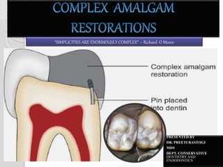
  • 1. PRESENTED BY DR. PREETI RASTOGI MDS DEPT. CONSERVATIVE DENTISTRY AND ENDODONTICS “SIMPLICITIES ARE ENORMOUSLY COMPLEX” – Richard O Moore
  • 2. OUTLINES  DEFINTION  CLASSIFICATION OF CORONAL TOOTH DESTRUCTION  EXTRA RETENTIVE DEVICES  RATIONALE TO USE PINS  INDICATIONS FOR PINS  ADVANTAGE  DISADVANTAGE  CLASSIFICATIONS OF PINS  DIRECT PIN  PIN MATERIAL  PRINCIPLE OF PIN PLACEMENT  FACTORS AFFECTING RETENTION OF PIN IN TOOTH STRUCTURE  FACTORS AFFECTING RETENTION OF PIN IN RESTORATIVE MATERIAL  COMPLICATION DURING PIN PLACEMENT  FAILURE OF PIN RETAINED RESTORATION  EFFECT OF PIN ON PULP  AMAGAPIN  PIN RETAINED CAST RESTORATION COMPLEX AMALGAM RESTORATION 2
  • 3. The operative dentist is confronted with restoration of extensively damaged teeth in routine. Many a times, the damage, which may be because of caries, trauma or previous restorations, involves half or more than half of the tooth structure. The remaining tooth structure is not sufficient to retain the restoration and require modification of classic preparation design by incorporation of various retentive means. Such restorations, which require extra retentive device for their retention, are labeled as ‘Complex restorations'. COMPLEX AMALGAM RESTORATION 3
  • 4.  According to Sturdevant – ◦ Complex restorations are used to replace any missing structure of teeth that have fractured, have severe caries involvement, or have existing restorative material.  These restorations usually involve the replacement of one or more missing cusps and require additional means of retention. COMPLEX AMALGAM RESTORATION 4
  • 5. HISTORY In 1897, Arthur described the use of anchor screws in the dentin to retain restorations. The pin amalgam restoration became widely accepted after Dr. Miles Markley popularized it in 1958. In 1969, Moffa et.al reported on the retentive properties of three different pin designs in dentin and amalgam. COMPLEX AMALGAM RESTORATION 5
  • 6.  Location, as well as extent of coronal destruction, plays an important role in selection of material and design of cavity preparation employed in restoration of tooth. COMPLEX AMALGAM RESTORATION 6 Treatment options Minimal Moderate Severe Central (which occurs in the central portion of the tooth ) •Amalgam •Composite •Bonded amalgam •Sandwich technique •Amalgam core+ crown Peripheral (which occurs on the axial surfaces of the teeth ) •Amalgam •Composite •Pin Amalgam •Pin Composite •Cast restoration •Crown •Full crown Combined (which incorporates destruction in both areas ) •Amalgam •Pin amalgam •Onlay •Amalgam core+ crown •Cast pin restoration
  • 7. To compensate the lost tooth structure, one or more than one retentive device is utilized The routinely used retentive devices are: i. Slots ii. Grooves/Locks iii. Pins COMPLEX AMALGAM RESTORATION 7
  • 8.  Slots are given to increase the surface area for the restoration.  A 0.75-1.0 mm deep and 1.0- 3.0 mm wide cut is given on the pulpal and/ or cervical wall.  This rectangular depression in these walls increases the bulk for the restoration, and also increases the area for bonding. COMPLEX AMALGAM RESTORATION 8 Dentinal slots are prepared approximately 1 mm deep and 0.5 to 1 mm inside the Dentinoenamel junction (DEJ)
  • 9.  Multiple grooves can also be given for enhanced resistance. Care should be taken to place the grooves in one plane. More than one groove per wall is rarely indicated and if necessary, can be given keeping proper parallelism and dentin around each groove. COMPLEX AMALGAM RESTORATION 9 A retention lock is a prepared groove whose length is in a vertical plane and which is in dentin. GROOVES LOCKS Grooves are given in indirect restorations Locks are given in direct restorations Groove extends upto the cavosurface margin (from cervical to cavosurface) Lock extends upto the pulpal wall (from cervical to pulpal) Groove maintain the parallelism of walls Lock converge occlusally The grooves/locks are given at axiobuccal and axio-lingual line angle, inside dentine- enamel junction, putting more pressure on buccal and lingual walls rather than at the axial walls. Placement of retention locks. A, Position of No. 169L bur to prepare the retention lock. B, Lock prepared with No. 14 bur.
  • 10. • A pin retained restoration is defined as any restoration requiring the placement of one or more pins in dentin to provide adequate resistance and retention form. • [Sturdevant] • A pin is an extension of a restoration into a prepared hole or a metal rod secured in a hole drilled in dentin for the purpose of retaining a restoration in or on the tooth. • [Atlas of operative dentistry] • A pin is small rod that fits into a channel drilled into dentin away from the pulp space. It is also referred as a dentinal pin or a parapulpal pin. • [Richard J, Shillinburg D.C.N.A Vol 37(3) 1993] COMPLEX AMALGAM RESTORATION 10 In 1958, Dr Miles Markley introduced stainless steel pins to provide retention and resistance in extensively decayed teeth.
  • 11. Pins help to support the restorative materials and resist their dislodgement in severely damaged and weakened teeth. Unlike restoration with conventional cavity preparation pin retained restoration provide efficient and adequate retention with the least sacrifice of healthy tooth structure. With the use of pins, cavity preparation can also be limited to only damaged surfaces thereby preserving esthetics and contours. Various studies concluded that stainless steel pins in amalgam did not actually strengthen it. Hence, the use of pins is restricted for extra retentive purposes. Pins are auxiliary aids of retention and are used only after primary retentive features like establishment of parallel walls, boxes and grooves as are not sufficient to provide the desired amount of retention. COMPLEX AMALGAM RESTORATION 11
  • 12. 1. Pins are indicated as auxiliary aids of retention in badly broken down or mutilated teeth, large class II, class III, class IV and class V cavity preparations. 2. In teeth with guarded prognosis, i.e. in endodontically and periodontically involved teeth, pin retained restorations are more useful than comparatively expensive treatments. 3. Pins may be used in foundations for full or partial metal or metal ceramic restorations. 4. When cost is a major factor for the patient, pin retained restorations may be a cheaper alternative in complex situations. 5. For Geriatric and debilitated patients, pin amalgams are the preferred choice over cast restorations. COMPLEX AMALGAM RESTORATION 12
  • 13. 1)If the patient has significant occlusal problems, 2) If the tooth cannot be restored properly with direct restoration because of anatomic or functional considerations (or both). 3)If the area to be restored has esthetic importance for the patient. COMPLEX AMALGAM RESTORATION 13
  • 14.  Conservation of tooth material: More conservative than tooth preparation for cast restoration.  Resistance and retention form: Use of pin and slots increases the resistance and retention of the restoration  Number of appointments: Relatively less time consuming than cast restorations, which require multiple appointments.  Cost factor: Comparatively less expensive than cast restorations for salvaging badly broken down teeth. COMPLEX AMALGAM RESTORATION 14
  • 15.  Dentin fracture: Use of pins in teeth where less dentin is present, may result in stresses in dentin in form of craze lines or cracks  Strength of amalgam: Compressive strength is not increased by use of pins, but there is decrease in tensile and transverse strength of amalgam  Perforations: Using bur or pin in wrong direction can cause pulpal exposure or perforation of external tooth surface.  Microleakage: If pin ends appear on or near to the surface of the restoration, it may result in microleakage around the pins.  Tooth anatomy: Sometimes, it is difficult to achieve optimal contours and occlusal contacts with these restorations. COMPLEX AMALGAM RESTORATION 15
  • 16. Pins can be classified as: Direct pins/non- parallel pins Cemented pins ••Friction locked pins Self-threading pins (most popular) Indirect pins/ parallel pins Cast gold pins Wrought precious metal pins COMPLEX AMALGAM RESTORATION 16
  • 17. INDIRECT PINS  Are slightly undersized to their pinholes and are the integral part of the cast restoration.  Are known as parallel pins as the method necessitates placement of pins parallel to each other as well as parallel to the path of insertion of the restoration.  Retention offered is less as compared to non parallel pins.  Two types of pins are used: Cast gold pins & Wrought precious metal pins COMPLEX AMALGAM RESTORATION 17
  • 18. CAST GOLD PINS  Have relatively smooth surface.  Restorations using these pins are fabricated by keeping the nylon bristles or plastic pins in the pinholes on which the rest of the restoration is built in the conventional form with blue inlay wax.  The whole assembly in then invested and casted with pins jamming an inherent part of the cast restoration. COMPLEX AMALGAM RESTORATION 18
  • 19. WROUGHT PRECIOUS METAL PINS  They have surfaces that is deformed or roughed by means of threaded or Knurled patterns.  These pins are alloys of gold, platinum palladium or platinum indium.  The pins are placed in the pinholes and are induced in the wax pattern.  Their high melting point and tarnish resistance enable them to be incorporated into the final gold casting.  These are 20-30% more retentive than smooth cast pins. COMPLEX AMALGAM RESTORATION 19
  • 20.  Direct pins are usually made of stainless steel, and inserted into dentin followed by the placement of a restorative material like silver amalgam, resin or cement directly over them.  Other materials of which the pins can be made of are silver, titanium, stainless steel with gold plating, etc.  These have also been referred to as the non-parallel pins since they can be inserted directly into the tooth structure and hence need not be parallel.  Category of pins includes: COMPLEX AMALGAM RESTORATION 20 Three types of pins. A, Cemented. B, Friction-locked. C, Self- threading
  • 21.  Markley introduced cemented pins in 1950s to achieve retention in a large silver amalgam restoration.  In this technique, the pins are 0.0013 " - 0.0023" smaller than their pin channels and the difference in diameter provides space for the cementing medium.  Cemented pins are indicated in cases where: o Least crazing and stresses are desired in the remaining tooth structure, e.g. endodontically treated teeth, o Bulk of dentin to accommodate the pin is limited, o There is no other choice but to place the pin near the dentino-enamel junction and o Dentin has lost its elasticity because of sclerosis or dehydration. o It is the preferred technique for class IV preparations. COMPLEX AMALGAM RESTORATION 21
  • 22. T E C H N I Q U E The pin is held with forceps and coated with cement. Pin hole is dried with endodontic paper points and coated with cement with help of endodontic file, explorer or lentulospiral. The length should be such that after seating the pin into the pin channel completely, the pin extends not more than 2-3 mm above the base. If the pin channel is directly accessible, cut the pin wire extra-orally to the desired length with a wire cutter or a Dial-A-Pin cutter. Cutting a pin after cementation may break the cement bond and dislodge it. Pinholes extending 2 - 4 mm into dentin are prepared using twist drills. Commonly utilizes pins in the form of stainless steel wires, which are serrated or threaded and cut to the required length. COMPLEX AMALGAM RESTORATION 22
  • 23. MODIFIED TECHNIQUE  This technique was later modified using threaded stainless steel pins of the same size as the twist drill.  Most commonly used size is the 0.027".  The advantages offered by this technique are: ◦ Close contact between the pin and channel ◦ Increased lateral stability.  The pin is cut and modified by creating a longitudinal facet with a carborundum disc.  This facet serves as a vent and is necessary to allow escape of excess cement especially when the pin and the channel diameters closely match. COMPLEX AMALGAM RESTORATION 23
  • 24.  Cemented pins are approximately 0.001"-0.002" smaller than their pinholes and hence are more likely to be seated to the full depth of the hole.  Since they are passively retained in the dentin, they virtually place no stress on the surrounding dentin during or after placement.  Because the cement seals the interface between the pin and the tooth, chances of microleakage are reduced.  These can be cut or bent to their final configuration before fixing them in the pin holes. COMPLEX AMALGAM RESTORATION 24
  • 25.  They offer less retention compared to the friction locked and threaded pins.  It is often difficult to insert cement into the pinhole and later locate the hole after cement has been introduced.  At times, a poorly cemented pin is easily dislodged when the filling material is being inserted.  Greater time is required for the mixing and hardening of the cement. COMPLEX AMALGAM RESTORATION 25
  • 26.  Goldstein introduced the friction locked pins to improve the disadvantages of cemented pins.  These pins are 0.001" larger than their pin channels and hence utilize the elasticity of dentin for retaining the tapped pins in a vise like grip.  These pins are indicated in o Teeth that are vital and periodontally sound, o Where direct access is possible so that the tapping force can be applied parallel to the long axis of the pin. o When sufficient amount of dentin is available to surround the pin and in no way should they be placed closer than 1.5 mm to the dentino enamel junction. COMPLEX AMALGAM RESTORATION 26
  • 27. T E C H N I Q U E The pin is felt to reach the bottom of the pinhole by sense of touch and sound. Forces are applied until the established mark on the pin reaches the cavity floor. A mallet is then used to apply force parallel to the axis of the pin. The pin is inserted into a pin setter and carried to pin hole. The depth to which pin channel has been drilled is marked on the pin. Desired length of the pin is cut extraorally. A self-centering spiral drill mounted in a low speed handpiece is used to prepare the pin channel in dentin to a depth of 2-3 mm, 1.5 mm inside the DEJ COMPLEX AMALGAM RESTORATION 27
  • 28.  Cement is not required so one does not have to wait for the cement to set and other related problems.  Pins acquire stability from the moment they are inserted.  Better retention than the cemented pins. COMPLEX AMALGAM RESTORATION 28
  • 29.  The length of the pin is judged by trial and error. It cannot be removed from dentin for cutting to the desired length once inserted.  Bending or contouring of the pin after it has been inserted into the pinhole leads to further stresses.  Driving pins into their respective pinholes generates stresses in dentin in the form of cracks or craze lines.  Many a times, the pins do not reach the full depth of the channel because of gouging, and hence may lose some of their retentive capacity.  Microleakage is higher than for cemented pins, if the overlying restoration leaks. COMPLEX AMALGAM RESTORATION 29
  • 30.  Going introduced the use of threaded pins.  Threaded pins are 0.0015 "-0.002" larger than their pin channels they are retained by the elasticity of dentin.  They actively engage the tooth structure through their threads similar to a screw inserted into a wooden block.  Threaded pins are most popular amongst the three pin systems due to their ease and rapidity of insertion, and maximum retention offered.  Threaded pins are indicated in: o Vital teeth and where maximum retention is desired. o When sufficient amount of dentin is available to surround the pin. COMPLEX AMALGAM RESTORATION 30
  • 31. Four varieties of threaded pins are available depending on their sizes (in decreasing order of sizes) as: Regular - 0.030", 0.031" Minim - 0.024 " 0.025" Minikin - 0.019", 0.020" Minuta - 0.014", 0.015" COMPLEX AMALGAM RESTORATION 31 Four sizes of the Thread Mate System (TMS) pins. A, Regular (0.031 inch [0.78 mm]). B, Minim (0.024 inch [0.61 mm]). C, Minikin (0.019 inch [0.48 mm]). D, Minuta (0.015 inch [0.38 mm]).
  • 32. The four basic designs of threaded pins are: Standard design Self shearing single pin design Two-in-one design and Disposable latch head design COMPLEX AMALGAM RESTORATION 32 Five designs of the Thread Mate System (TMS) pins. A, Standard. B, Self- shearing. C, Two-in-one. D, Link Series. E, Link PlusStandard pin Self-shearing pin Two-in-one Link series Link plus series
  • 34. ARMAMENTARIUM FOR PIN INSERTION  Two instruments for the insertion of threaded pins are available: ◦ (1) Conventional latch-type contra- angle handpieces and ◦ (2) TMS hand wrenches.  The latch type handpiece is recommended for the insertion of the Link Series and the Link Plus pins.  The hand wrench is recommended for the insertion of standard pins. COMPLEX AMALGAM RESTORATION 34
  • 35. HAND WRENCH  Provides tactile sense during threading of pin into dentin.  Hand wrench is recommended for insertion of standard pins.  A Standard design pin is placed in the hand wrench and slowly threaded clockwise till definite resistance is felt when the pin reaches the bottom of the pin hole.  Pin should then be rotated one- quarter to one half turn counter clockwise to enable the exposed sharp corners to cut threads into wall of dentin and thus reduce dentinal stress created by end of the pin pressing dentin. COMPLEX AMALGAM RESTORATION 35 Hand wrenches for the Thread Mate System (TMS) pins. A, Regular and Minikin. B, Minim. C, Minuta. D, Link Series and Link Plus.
  • 36. CONVENTIONAL LATCH TYPE CONTRA-ANGLE HANDPIECE  A 10:1 reduction gear contra-angle hand piece is available to insert the pins.  During the insertion of the pins the low speed hand piece increases the tactile sense of the operator.  It also reduces the risk of stripping the threads in the dentin once the pin in place.  The latch – type handpiece is recommended for the insertion of the Link Series and the Link Plus pins.  When using the latch-type handpiece, insert a Link Series or a Link Plus pin into the handpiece and place the pin in the pinhole. Activate the handpiece at low speed until the plastic sleeve shears from the pin. Then remove the sleeve and discard it. COMPLEX AMALGAM RESTORATION 36 Conventional latch-type contra- angle handpiece Handpiece chucks for the Thread Mate System (TMS) (A) Regular self-shearing and Minikin pins (B) TMS Minuta pins
  • 37. STANDARD DESIGN  The standard pin is a full length pin, i.e. 7.0 mm long which can be cut to the required length after placement.  It provides a flattened head for engagement with the hand wrench or the handpiece chuck.  It is threaded to place until it reaches the bottom of pinhole as judged by tactile sense.  ADVANTAGE: It can be reversed one quarter to one half turn following insertion to full depth to reduce stress created at the apical end of the pinhole.  Pin height can be cut to appropriate length after placement. COMPLEX AMALGAM RESTORATION 37
  • 38. SELF SHEARING DESIGN  The self shearing single pin design is available in varying lengths depending upon the diameters.  The pin is designed so that when it reaches the bottom of the pinhole, the head separates automatically at the shear line, leaving a portion of it to project from the dentin.  Shearing occurs when there is marked resistance to turning, i.e. pin insertion is torque limited.  A flattened head on one end of the pin is shaped to engage the slot in the hand wrench or the handpiece chuck. COMPLEX AMALGAM RESTORATION 38
  • 39. TWO - IN – ONE DESIGN  The two-in-one design is one in which two pins are connected to each other at a joint.  This joint serves as a shear line for the peripheral pin.  It is approximately 8 - 9 mm in length and provides two pins of equal lengths.  It has a flattened head to engage the slot of the hand wrench or the handpiece chuck.  Out of the two pins, one which is released  First is known as the pin A or the peripheral pin, where as the one which is released  Second is known as the pin B or the wrench attachment pin. As the name indicates, it is pin B which provides a head for attachment to chuck or wrench.  After the first pin has been threaded to the floor of the pin channel, it shears off at the connecting joint leaving behind the second pin along with its attachment to be used in another pin channel.  One major advantage with the two-in-one pin is that the hand piece need not be reloaded during two pin insertions. COMPLEX AMALGAM RESTORATION 39
  • 40. LINK SERIES  The disposable latch head design has a plastic sleeve/ head designed to fit in a slow speed contrangle hand piece.  The pin appears to float freely in the plastic sleeve.  This aids in self alignment as the pin is driven into the pinhole.  After the pin reaches the bottom of the pinhole, the resistance offered causes the head to separate from the pin at the shear line.  The plastic sleeve is then discarded. To facilitate identification of different sizes of pins, the plastic sleeves are color coded.  In the commercially available TMS system (Thread Mate System) of pins, this design is known as the 'Link Series'. COMPLEX AMALGAM RESTORATION 40
  • 41. LINK PLUS DESIGN This design is similar to the link series design with following modifications:  Sharper threads,  A shoulder stop at 2mm and  A tapered tip to more readily fit the bottom of the pinhole.  This design in the TMS system is known as the 'Link Plus Series'.  It is believed that stresses induced in the surrounding dentin (especially the apical stresses) during pin insertion are greatly reduced because of these modifications.  Are also self shearing.  May be available as single or two – in- one pins.  Provides a 2.7 mm length of pin to extend out of the dentin, which usually needs to be shortened. COMPLEX AMALGAM RESTORATION 41
  • 42. Any sharp ends are smoothened with a round bur or carborundum disc. Any excess length is removed with a rotating bur or cutting pliers. If required, the pin is bent slightly with a contouring plier After the pin has been placed into dentin, it is checked from all sides for length and angulation. The ideal pin length extending out of dentin should be 2 mm while providing space for 1 mm of restorative material peripheral to the pin and 2 mm occlusal to the pin. On reaching the full depth, resistance is increased and the pin shears off at the shear line or disengages from the hand piece drive. For manual insertion, pins are attached to the hand wrench and threaded slowly into position. Tactile sense is a major factor in determining whether the pin has reached the bottom of the pin channel. For mechanical insertion, pins are engaged in the appropriate hand piece chuck to be inserted into the hand piece. With the hand piece operating at slow speed, the pin is inserted with light pressure. Prepare the pin channel in dentin to a depth as required. T E C H N I Q U E 42 COMPLEX AMALGAM RESTORATION
  • 43.  Versatile design.  Wide range of pin sizes.  Color coding allows ease of use.  Gold plating elimination corrosion.  Ease of insertion.  Maximum retention is offered. COMPLEX AMALGAM RESTORATION 43 •Excessive stresses in the form of cracks and craze lines are generated in the surrounding enamel and dentin, especially with the large sized pins. •Pins may need to be bent, cut or contoured after insertion, which places extra stress on the tooth or may loosen the pin. •When the pin is forced into the channel, it may strip the sides of the dentin resulting in a loose fit. •Pins may fail to seat completely. •Microleakage is higher than the cemented pins if the overlying restoration leaks.
  • 44. “L” OR “T” SHAPED THREADED PINS  Mattos (1973) introduced these pins to overcome the need for bending pins after their placement.  These are well suited for Class IV preparations as it devoids the need for a second pin at the incisal third.  The transverse portion of the L is allowed to rest in a depression specially prepared in the dentin.  These pins have either a square head or a flat extended head for attachment to the hand wrench.  The extended head has a shallow groove at its junction with the pin at which it separates once the pin reaches the bottom of the pinhole. COMPLEX AMALGAM RESTORATION 44
  • 45.  Materials used for the construction of pins include: Stainless steel, Titanium, Silver, Cast gold alloys, Platinum-palladium alloys, Platinum-iridium alloys, Plastic, Aluminium, Acrylic.  Stainless steel, titanium and silver pins are commonly used for the direct/non-parallel pin technique. COMPLEX AMALGAM RESTORATION 45
  • 46.  STAINLESS STEEL PIN ◦ Advantage:  stronger than its gold and titanium counterparts but has the ◦ Disadvantages:  of getting corroded and non-adherence to silver amalgam and composite restorative materials.  TITANIUM PINS ◦ Advantages:  Least corrosive and  Most biocompatible. ◦ Disadvantages:  Strength and modulus of elasticity is less compared to that of stainless steel and high gold content alloys.  Do not show any adherence to silver amalgam or composite restorative materials. COMPLEX AMALGAM RESTORATION 46
  • 47.  SILVER PINS  Introduced with the idea of achieving a true adhesive bond between the pin and silver amalgam material so as to render them an integral part of the restoration. ◦ Advantage:  These have excellent bond with the silver amalgam restorative material. ◦ Disadvantage:  Solid silver pins are soft and easily deformed.  Pins constructed in CAST GOLD, PLATINUM- PALLADIUM OR PLATINUM-IRIDIUM are used with the indirect/ parallel pin technique. These pins are relatively corrosion resistant. COMPLEX AMALGAM RESTORATION 47
  • 48.  PLASTIC PINS are used in the indirect parallel pin technique but do not serve as a part of the final restoration. They are meant for taking impressions of the pinholes for fabricating a cast gold alloy restoration.  ALUMINIUM PINS are used for retaining a temporary restoration until the final restoration is fabricated and inserted.  ACRYLIC PINS have been tried for use with composite resins, but are not very popular. Silver plated and gold plated stainless steel pins have also been tried to achieve a true adhesive bond between steel and silver amalgam. However, these pins did not prove to be very successful.  GOLD PLATED PINS are usually preferred under composite resins to reduce the 'shine through' of stainless steel pins. COMPLEX AMALGAM RESTORATION 48
  • 49. 1. Number of pins 2. Pin site 3. Pin orientation 4. Pin diameter 5. Pin length 6. Inter pin distance COMPLEX AMALGAM RESTORATION 49
  • 50.  The number of pins that should be given in a tooth are based upon the simple rule of:  Modify this rule depending upon the amount of tooth structure missing, the amount of retention desired, the amount of dentin available and the size of pins.  Increasing the number of pins increases the chances of increased stresses, pulpal damage and/ or perforation, hence the aim should be to achieve adequate retention with minimum possible number of pins. COMPLEX AMALGAM RESTORATION 50 Unnecessary use of pins can cause stresses and voids in restoration one pin per missing cusp or one pin per missing axial line angle.
  • 51.  Location for a pin requires knowledge about the pulpal anatomy and external contours of the concerned tooth, the patient's age, a recent radiograph of the tooth, and a periodontal probe.  The radiograph gives an indication of the pulpal anatomy, external contours of the tooth, and the distance between the pulp space and the external outline of tooth on mesial and distal sides.  The most desirable locations for pinholes are the facio/linguoproximal line angles or corners of the tooth and the least desirable locations are in the middle of the facial, lingual, mesial and distal surfaces of a tooth.  Placing pinholes in locations overlying furcations and concavities are particularly hazardous.  Place pins in locations where they will be surrounded by optimum bulk of dentin and restorative material.  The site should be half way between the pulp and the dentino-enamel junction/ external surface of the tooth. COMPLEX AMALGAM RESTORATION 51
  • 52.  There should be at least 1.0 mm of sound dentin around the whole circumference of the pin.  Pins should be located no closer than 0.5 mm to the dentino-enamel junction to avoid crazing of enamel.  Dentin thickness around each pin should be at least 2.5 times the diameter of the pinhole.  Pin placement should allow at least 1.0 mm of dentinal thickness between the pulp and the pin to prevent any severe inflammatory response.  Pin holes should be located on flat surfaces to prevent drill from slipping.  When three or more pins are to be placed in the same tooth, they should preferably be located in different planes/levels to preclude interaction of stresses in the same plane. COMPLEX AMALGAM RESTORATION 52
  • 53. COMPLEX AMALGAM RESTORATION 53 Ideal site for pin placement in mandibular teeth Ideal site for pin placement in maxillary teeth MECHANO- ANATOMICAL PRINCIPLES FOR PIN PLACEMENT
  • 54. COMPLEX AMALGAM RESTORATION 54 Tooth Site for placing pin Areas to be avoided Central and lateral incisors Middle of labial gingival floor Incisal with minimum 2 mm of depth Middle of lingual gingival floor. Proximolingual floor, with insufficient depth Canine Close to labial and lingual proximal part of tooth Incisal, close to incisal angle Gingival pin close to groove or concavity First and Second Premolars Close to proximobuccal and lingual corner of the tooth Middle of gingival floor buccally and lingually Mesiogingival floor First and Second Molars Gingival floor close to distolingual part of tooth Gingival floor mesial to buccal part of tooth Any part of gingival floor occlusal to furcation Third Molar Because of variable anatomy, pin is placed after radiographic evaluation PIN PLACEMENT FOR MAXILLARY TEETH
  • 55. COMPLEX AMALGAM RESTORATION 55 PIN PLACEMENT FOR MAXILLARY TEETH
  • 56. COMPLEX AMALGAM RESTORATION 56 Tooth Site for placing pin Areas to be avoided Central and lateral incisor Because of less thickness of depth, pins are avoided except in teeth where pulp chamber is very much reduced Canine Close to labial and lingual proximal part of tooth Incisal, close to incisal angle Gingival pin close to groove or concavity First and second premolars Close to labial and lingual proximal part of the tooth Middle of gingival floor buccally and lingually First and second molar Distolingual portion of gingival floor Distobuccal and mesiolingual part of gingival floor Mesiobuccal corner of gingival floor Third molar Because of variable anatomy, pin is placed after radiographic evaluation PIN PLACEMENT FOR MANDIBULAR TEETH
  • 57. COMPLEX AMALGAM RESTORATION 57 PIN PLACEMENT FOR MANDIBULAR TEETH
  • 58.  Pins should be oriented parallel to the long axis of the tooth.  However in excessively cervically placed areas towards the cemento-enamel junction where sharp constrictions are likely to be present and dentin thickness is reduced, it is mandatory to direct the pin parallel to the closest external surface of the tooth and then bend it slightly as needed.  This would mean compromising on factors like increasing stresses in the tooth but would save the clinician of the trauma of perforation.  The best possible way to determine presence of any abnormal contours is to place a probe adjacent to the surface close to the intended location and examine its direction. COMPLEX AMALGAM RESTORATION 58
  • 59.  The selection for the diameter of the pin depends upon o the amount of dentin available o the size of the concerned tooth and o the amount of retention required.  Generally, increasing the diameter of the pin offers increased retention, but large sized pins are also associated with a heavy concentration of stresses in dentin.  Preferably, the depth should be more than the diameter. COMPLEX AMALGAM RESTORATION 59 If pin size is greater than pin channel it can cause stresses in the dentin: (A) Pin diameter less than pin channel; (B) Showing stresses in dentin when pin diameter is more than pin channel
  • 60.  The optimum ratio of pin length in dentin to pin length in restorative material varies with the different types of pins, i.e. o Cemented pins it is 3.0 mm and 2.0 mm; o Friction locked pins it is 3.0 mm and 3.0 mm; o Threaded pins it is 2.0 mm and 2.0 mm.  Preferably the length of the pin inside the dentin and the length of the pin in restorative material should be equal. COMPLEX AMALGAM RESTORATION 60 More is the pin in the restoration or dentin, more are the stresses
  • 61.  When greater than two pins are to be placed in the same tooth, interpin distance should be considered to allow space for insertion of restorative material between the pins and prevent excessive concentration of residual stresses in dentin.  The optimum interpin distance depends upon the type and size of pins.  The minimal interpin distance is: o 2.0 mm for cemented pins, o 4.0 mm for friction locked pins, o 3.0 mm for Minikin threaded pins and o 5.0 mm for Minim threaded pins.  The accepted principle is to have 2.0 mm of dentin around each pin. COMPLEX AMALGAM RESTORATION 61 Lesser is the interpin distance, more are the stresses generated
  • 62. TOOTH PREPARATION FOR PIN-RETAINED AMALGAM RESTORATIONS  INITIAL TOOTH PREPARATION:  When the facial or lingual extension exceeds two thirds the distance from a primary groove toward the cusp tip (or when the facial lingual extension of the occlusal preparation exceeds two thirds the distance between the facial and lingual cusp tips), reduction of the cusp for amalgam is required for the development of adequate resistance form. COMPLEX AMALGAM RESTORATION 62
  • 63.  Depth cuts should be made on the remaining occlusal surface of each cusp to be capped, using the side of a carbide fissure bur or a suitable diamond instrument.  The depth cuts: ◦ 2mm deep minimum for functional cusps. ◦ 1.5mm deep minimum for non functinal cusps.  Using the depth cuts as a guide, the reduction is completed to provide for a uniform reduction of tooth structure.  When reducing only one of two facial or lingual cusps, the cusp reduction should be extended just past the facial or lingual groove, creating a vertical wall against the adjacent unreduced cusp.  Extending the facial or lingual wall of the proximal box to include the entire cusp is indicated only when necessary to include carious or unsupported tooth structure or existing restorative material.  when possible opposing vertical walls should be formed by converge occlusally, to enhance primary retention form.  The pulpal and gingival walls should be relatively flat and perpendicular to the long axis of the tooth. COMPLEX AMALGAM RESTORATION 63
  • 64. FINAL TOOTH PREPARATION  Removal of any remaining infected carious dentin or removal of remaining old restorative material is accomplished.  A liner can be applied, if needed and if used should not extend closer than 1mm to a slot or a pin.  Coves and retention locks should be prepared, when possible. Locks and coves should be prepared before preparing pinholes and inserting pins.  If additional retention is indicated, slots may be prepared along gingival floor, axial to the DEJ instead of, or in addition to, in pinholes. COMPLEX AMALGAM RESTORATION 64 Lock (A), slots (B), and coves (C).
  • 65. COMPLEX AMALGAM RESTORATION 65 Capping the cusp with amalgam. A, Comparison of the mesial aspects of normally extended (left) and extensive (right) mesio-occluso-distal tooth preparation. The resistance form of the mesiolingual cusp of extensive preparation is compromised and indicated for capping with amalgam. B, Preparing depth cuts. C, Depth cuts prepared. D, Reducing the cusp. E, Cusp reduced. F and G, Final restoration
  • 66. Pin hole preparation  Three basic instruments are needed for the pin channel preparations: ◦ Twist drill ◦ No. 1, 2, 3 round burs:  With which a leading hole is established, in the centre of which the pin channel drilling is started.  This aids in avoiding any skidding of the twist drill. ◦ Measuring probes or depth gauze:  Used to verify the depth of the pin channel. COMPLEX AMALGAM RESTORATION 66
  • 67. TWIST DRILL  Pinholes are prepared using a device called 'twist drill’ (Kodex drill).  Twist drill is an end cutting instrument that performs cutting when rotated clockwise at low speeds. The drill has two blades which revolve at precisely equidistant points from the centre, and is helix fluted to allow escape of the cutting debris. Twist drills may be either made in one piece or two piece. ◦ One piece twist drill is made of steel, is less expensive and more likely to fracture. ◦ Two piece drill is made of steel that is swaged onto an aluminium shank, is more expensive, stronger and less likely to fracture.  The recommended speed for drilling channels is 300-500 rpm (ultralow speed) or 1000 rpm (low speed). COMPLEX AMALGAM RESTORATION 67 Two types of Kodex Drill: a) standard b) depth limiting drill
  • 68.  With drill in latch type contra angle handpiece, place drill in gingival crevice beside the location for pinhole, position it flat against external surface of the tooth.  Then, without changing the angulation obtained from the crevice position, move handpeice occlusally and place the drill in the previous pilot hole.  With the drill tip in its proper position and with the handpiece rotating at very low speed, apply pressure to the drill and prepare the pinhole. COMPLEX AMALGAM RESTORATION 68 ANGULATION OF TWIST DRILL MOVING THE DRILL OCCLUSALLY IN THE SAME ANGULATION
  • 69. Four basic designs of twist drills:  (a) Regular twist drills which have their cutting parts 4.0 mm or more in length without a limiting shoulder/ stop.  (b) Limited depth twist drills which have a stop or shoulder to limit the depth of cutting. These stops are either prefixed or adjustable. When fixed, they are generally located at 2.0 mm lengths from the cutting end of the drill.  (c) Miniature twist drills which are regular or limited depth type but their overall length is shorter (17.0 mm) and  (d) Twist drills with parallelometer attachment. These again are regular or limited depth type drills designed to function with paralleling instruments. They have narrowed shanks that pendulate freely in the bur sleeve of the handpiece and a sleeve to fit in the parallelometer. Their use becomes necessary when parallel pins are required under cast restorations. COMPLEX AMALGAM RESTORATION 69 Twist drills: (A) Standard drill; (B) Depth limiting drill
  • 70. DRILLING  The optimal depth of the pinhole into the dentin is 2mm, a depth limiting drill should be used to prepare the hole.  When the location for starting a pinhole is neither flat nor perpendicular to the desired pinhole direction, either flatten the location area or use the standard twist drill, whose blades are 4-5 mm in length, to prepare a pinhole that has an effective depth.  The proposed pinhole locations are marked with a marker before the pin channels are prepared with the twist drill. A No.1/4 round bur at low speed is dipped to about half the diameter at these marks to create starting points known as lead holes or pilot holes. COMPLEX AMALGAM RESTORATION 70 Flat surface is chosen for drilling because on sloping surface the shoulder of depth limiting drill will strike dentin before full depth of pin channel is drilled. Pilot hole (dimple) prepared with a No. 1/4 bur.
  • 71. The following points need to be kept in mind when drilling a pin channel:  Repeated insertion and removal of a drill in the same channel can result in enlarged channels and/ or conical or eccentric shapes of the channel.  Lateral stresses applied while drilling can induce additional stresses in dentin and increase the chances of drill breakage.  Rotating pin drills for longer period after they have reached the bottom of the pin channel can result in large sized holes.  Stopping the pin drill during the drilling procedure increases the chances of drill breakage.  After the pin channels have been completed, radiographs taken, their depths are read and confirmed with depth gauges that read in millimeters. The pins are inserted following the techniques described earlier for cemented, friction locked and threaded pins. COMPLEX AMALGAM RESTORATION 71
  • 72.  Following pin insertion, conditions may necessitate bending or trimming of pins.  Ideally, the maximum amount of bending and trimming should be performed prior to placement of pins.  After inserting the pins, evaluate the length and position of the exposed pin from all aspects especially the occlusal aspect.  At least 1.5 mm of the pin should be exposed, at least 1.0 mm of the space for restorative material around the periphery of the pin and at least 2.0 mm of space occlusal to the pin should be available.  Bending is required to facilitate condensation of restorative material in an occluso-gingival direction. Proper bending tools or contouring pliers should be used to bend the pin smoothly at a distance from the pin dentin interface. COMPLEX AMALGAM RESTORATION 72 A) The thread mate system (TMS) bending tool B) Use of the bending tool to bend the pin C) & D) The pin is bend to a position that provides adequate bulk of amalgam between the pin and the external surface of the final restoration
  • 73. COMPLEX AMALGAM RESTORATION 73 Use of hand instruments or spoon excavators are contraindicated as they are more likely to produce a sharp bend at the pin dentin interface and increase the chances of fracture. Bending a pin after it has been seated may cause stress development and fracture of the dentin or the pin.
  • 74.  Occasionally, replacement of a pin retained restoration may necessitate removal of pins.  Reusing the same pin around which the restorative material has been removed is associated with the danger that in function or in restoration removal, the pin may have been loosened.  Moreover, it is difficult to place pins at new sites because of ◦ Limited availability of dentin and the chances of pulpal exposure and external tooth perforation. ◦ Removing pins is advantageous, as the same pin sites could then be reused without much loss of tooth tissue. COMPLEX AMALGAM RESTORATION 74
  • 75. Methods for pin removal 1) Pin can be grasped directly with an artery forceps. • This is possible only when sufficient length of the pin is available for engagement by the ends of the forceps, and access allows forceps to be held in line with the pin. 2) A pin can be removed with a rotating bur that produces anticlockwise rotation in the pin. • This is possible when a bur rotating at high speeds is placed perpendicular to the pin and to its right or parallel to the pin. Only a fleeting contact should be made between the pin and the bur with the aim of unscrewing it rather than cutting it. This method can be used only for removing threaded pins. 3) A pin can be removed with ultrasonic tip. • The vibrating tip is held in contact with the pin and rotated anticlockwise in an unscrewing motion. The torque applied by the mechanical vibration of the ultrasonic tip in contact with the pin is responsible for its unscrewing. The prescribed method is used for removal of threaded pins. Ultrasonics can also be used for removal of cemented pins. Under ultrasonic vibrations, the cement is broken down and the dislodged pin easily removed. The first two methods cannot be employed, as the procedures require some amount of exposed pin for pin removal. Ultrasonics may be used with some degree of success. COMPLEX AMALGAM RESTORATION 75
  • 76. PINS, STRESSES AND TOOTH  Stresses are associated with insertion of friction locked and threaded pins in dentin. Stresses will be generated as pins are inserted into channels 0.001"-0.004" smaller than the diameter of the pins.  Insertion of larger pins into smaller pin channels is possible because of the elastic properties of dentin. Once the elastic limit of dentin is exceeded, plastic deformation occurs.  If the dentin's plastic limit is exceeded, microscopic and/ or macroscopic craze lines or cracks are generated.  These fracture lines can lead to involvement of pulp or periodontium, cracked tooth syndrome, gross fractures, loose restorations, etc.  Cemented pins are known to induce the least stresses, threaded pins induce intermediate stresses and friction locked pins induce the maximum stresses.  Friction-locked pins act as wedges and lateral stresses are the main type of stresses present around them, compared to threaded pins which are associated mainly with apical stresses.  Impact forces introduced during insertion of friction locked pins are probably responsible for greatly magnifying the residual stresses in dentin. With the threaded pins some of the induced stresses are reduced by cutting and eliminating stressed dentin. COMPLEX AMALGAM RESTORATION 76
  • 77. Factors which increasing the residual stresses in dentin are: • Pin morphology • Large diameter of the pin • Large difference between the pin and pin channel diameter especially in friction locked and threaded pins • Blunt threads • Narrow pitched threads, i.e. greater number of threads per unit distance • Excessively long threads extending outward from the core of the pin • Irregularities at pin ends induced during manufacturing or during adjustment • Inserting a flat ended pin into a chisel ended channel COMPLEX AMALGAM RESTORATION 77
  • 78. • Inserting pins into channels not prepared with matching drills • Placing pins close to each other causes interaction of the field of stresses of individual pins. This interaction is maximum when the interpin spacing is less than 2.0 mm. • Increasing the number of pins per tooth increases stresses. • Ratio of embedded pin and exposed pin length if not 1:1 induces harmful stresses.  Mismatch between the pin and pin channel circumference increases stresses by concentrating stresses at points of contact rather than being distributed evenly around the channel. This mismatch may be due to manufacturing defect, repeated insertion and removal of drill resulting in conical channels, because of drills with increased run out producing eccentric shaped channels. COMPLEX AMALGAM RESTORATION 78
  • 79.  A pin which is loose in its channel induces stresses on dentin when the overlying restoration is stressed. The magnitude of stress induced depends upon the amount and degree of pin movement in the channel.  An attempt to over drive the pin into its channel even after it has contacted the bottom, increases stresses.  Bending or shortening pins after they have been fully engaged in dentin can induce excessive stresses.  Incidence of cracks in enamel is higher with the friction locked and threaded pins and very negligible with the cemented pins. Friction locked pins are the most dangerous when placed at less than 1.0 mm from dentino-enamel junction. The least damaging are cemented pins, which have not shown to induce stresses even when placed at dentine- enamel junction.  Cutting channels with drills that are dull, vibrating and with laterally applied forces, increase the stresses in dentin.  Lesser the bulk of dentin surrounding the pin, greater are the stresses per unit volume of dentin. COMPLEX AMALGAM RESTORATION 79
  • 80. PINS, STRESSES AND RESTORATIVE MATERIAL  Originally, when pins were thought to reinforce amalgam in the same way as steel rods reinforced concrete.  Subsequent studies, however showed that pins did not strengthen or reinforce a restoration but assisted in the retention forms only.  Pins are likely to reduce the strength of amalgam and composite restorations because of the absence of any chemical union between the pin and restorative material at the interface.  Voids and irregularities are present at the interface, or the pin in Toto is believed to serve as a void in restorative material and hence act as a stress initiator. Fractures in the pin amalgam restorations are, therefore, commonly seen in planes involving pins.  The formation of corrosion products at the interphase of pin and restorative material, either because of presence of two dissimilar metals or because of corrosion properties of the pin itself, reduces the fracture strength of pin retained restorations. COMPLEX AMALGAM RESTORATION 80
  • 81. Factors relating to pins that decrease the compressive and tensile strength of a restoration are:  Pin ends in restoration may be wedge-shaped or irregular in shape, serving as areas of stress concentration.  Pins are close to or protrude through the outer surface of the restoration. This decreases the bulk of material between pin end and restoration surface, thereby not providing adequate strength to the material required for resisting mechanical loading, e.g. silver amalgam is weak if it is not present in thickness of 1.5-2.0 mm.  Pins are closer than 2.0 mm to each other. This increases the possibility of incorporation of voids because of the inability to properly insert and condense material between the pins and insufficient bulk of material is present around the pins.  An additional factor associated only with the tensile strength of restorative material is the relative direction of tensile stresses in relation to the direction of the pin. ◦ A 30-40% reduction in tensile strength of the restorative material is seen when the pins are at right angles to the direction of the tensile stresses during function. ◦ A 10% reduction is seen when the pins are at 45° to the direction of tensile stresses and no reduction in strength is seen when the pins are in line with the tensile stresses. COMPLEX AMALGAM RESTORATION 81
  • 82. FAILURES OF PIN RETAINED RESTORATIONS  In the dentin, i.e. fracture of tooth: ◦ Increased internal stresses ◦ Incorrect selection of site The solution is to reduce the area to a flat surface and re- drill a pinhole.  At the dentin/pin interface, i.e. pin pulls out along with the restoration: ◦ Improper pin engagement of dentin The treatment includes recementing if it is a cast pin restoration, or performing the whole procedure again if it is an amalgam restoration.  In the pin itself, i.e. pin fractures: ◦ Improper technique during pin placement Remove the remaining restorative material from the cavity preparation. Fractured pins are managed and the tooth is restored again. COMPLEX AMALGAM RESTORATION 82 Five possible locations of failure of pin-retained restorations: a) fracture of restorative material b) separation of pin from restorative material c) fracture of pin d) separation of pin from dentin e) fracture of dentin.
  • 83. COMPLEX AMALGAM RESTORATION 83 •At the pin/restoration interface, i.e. restoration pulls away from the pins: •Formation of corrosion products at the interface. • The treatment includes removal of any remaining restorative material. Pins are checked for loosening. Loose pins are managed and the restoration done again. •Failure of the restorative material itself, i.e. restoration fractures: • Improper matrix removal (pre-mature removal of the matrix should be avoided) • High points in restoration The treatment includes repair of the restoration. When restoration cannot be repaired, the remaining restorative material is removed and the tooth restored again.
  • 84. l. Drill breakage: can occur when:  Lateral stresses are applied while drilling,  Dull drills are used,  The drill is allowed to stop rotating while entering or exiting from dentin or anywhere in between.  SOLUTION: 'Precaution' is the only treatment. Removal of a broken drill is quite difficult. If removal is not possible, a new hole can be drilled 1.5 mm away from the first hole. 2. Pin breakage:  Excessive force is applied while driving the pin into its pin channel,  The pin is rotated despite being fully seated in the channel  The operator is not careful while bending the pin.  SOLUTION: Removal of a broken pin is quite difficult and it mainly depends upon the level of the pin breakage. When sufficient length of pin is available for holding, removal should be attempted. If unsuccessful in removing the pin or when the pin has broken at the level of dentin, a new hole can be drilled 1.5 mm away from the first hole. COMPLEX AMALGAM RESTORATION 84
  • 85. 3. Loose pins: Quite frequently the pins are loosely fitted in their channels. This may possibly be because of: ◦ Repeated insertion and removal of the pin drill enlarging the pin channel, ◦ Pin drill is rotated more than instructed, resulting in large sized channels, ◦ Manufacturer's discrepancy, i.e. poor quality control between the pin drill and pin sizes ◦ A self shearing pin fails to shear, resulting in stripped out dentin, Care should be taken that the pin drill rotates only for a brief moment.  SOLUTION: A single thrust without any lateral deflection of the twist drill avoids this complication. In case the pin is loosely fitted, then the channel should be enlarged with the next sized drill and a larger pin inserted.  If the pin, which is loose in the channel is of the largest available size, it is better to close the channel with appropriate materials and a new hole, 1.5 mm away from the first hole, is drilled.  A well fitted pin in the channel may also get loosened at a later stage. This often occurs while shortening the pin, when the rotating bur is held parallel to the pin or perpendicular to the pin on its right side, which causes the pin to rotate counter-clockwise. In this case, it is recommended to unwind the loosened pin completely. Since the pinhole has not been enlarged, a second pin of same size generally fits in well. 4. The pin shears off before having reached its full depth: SOLUTION: In such cases, the treatment includes unthreading the pin, cleaning the channel and inserting a second pin of the same size. COMPLEX AMALGAM RESTORATION 85
  • 86. 5. Twist drill dulling: Cutting edges of a twist drill are dulled when the drill is repeatedly used. Dull drills have decreased cutting effectiveness, induce more stresses in dentin, and are more prone to breakage. Failure to remove clogged debris may also give the impression of dull drills. Coated drills show an increase in effective diameter and hence produce large sized channels.  SOLUTION: Treatment includes preventing repeated insertions and avoiding lateral forces on the twist drill. Twist drills should be thoroughly cleaned with hydrogen peroxide and should be discarded after preparing a maximum of 20 channels. 6. The pin fails to bind and shear, but keeps rotating within its channel: The best solution is to cement the pin or use one size larger. 7. Heat generation:  Rise in temperature subsequent to the use of twist drills may be related to cutting deep channels, high rotational speeds used during channel preparations, large sized twist drills and repeated insertion of pin drills into dentin.  SOLUTION: Heat generation can be reduced by using 2.0 mm depth limiting drill and the smallest pin possible. Drills should be run at slow speeds. COMPLEX AMALGAM RESTORATION 86
  • 87.  8. Microleakage:  The use of pins conceivably aggravates the leakage problem by producing fine craze lines and cracks that behave as communication channels with the exterior and the pulp.  The leakage of saliva at the pin/ dentin and pin/ restoration interface predisposes to formation of corrosion products. Leakage with cemented pins occurs around its whole circumference, whereas with friction locked and threaded pins occurs in a semilunar pattern.  The dead space created by incomplete seating of pins may harbour bacteria and induce pulpal problems.  SOLUTION: Microleakage can almost be eradicated under amalgam restorations by applying cavity varnish on the entire cavity surface including the pin channels. However, when varnish is used under cemented pins their retention is drastically reduced. Retention of friction locked and threaded pins is not affected by use of cavity varnish. Pin channels prepared significantly inside the dentino enamel junction also reduce the possibility of cracks extending to the dentin defects or the external surface, hence reducing microleakage. COMPLEX AMALGAM RESTORATION 87
  • 88. 9. Perforation into the pulp space:  Pulp exposure under a pin is suspected if: ◦ Bleeding occurs in the pin hole following removal of the drill from the pin channel. ◦ Sudden lack of resistance is felt. ◦ Sudden pain is experienced in a tooth while drilling, if the tooth is not anaesthetized. ◦ The pin continues to thread greater than its intended depth.  Radiographs may aid in detecting a pulp exposure.  Factors increasing the chances of pulpal penetration include inappropriate positioning and direction of the pin channels, use of large sized pins in small teeth, increased number and depth of pins in a single tooth, etc.  SOLUTION: The treatment of pulp exposure by pin is similar to any other direct pulp cap procedure.  If the perforation is discovered while drilling the pin channel, haemorrhage is first controlled and then the channel filled and sealed with calcium hydroxide.  If the perforation is discovered after the pin has been inserted, remove the pin, control haemorhage and then place calcium hydroxide.  A new pin channel is then prepared 1.5-2.0 mm away from the first hole.  An alternative treatment is to control any haemorrhage and insert a sterile pin coated with calcium hydroxide just to the level of the pulp. Radiographs and pulp testing should be performed after every 3-6 months for confirming the vitality status of the pulp. COMPLEX AMALGAM RESTORATION 88 Pulp penetration while pin placement
  • 89.  Perforation onto the external tooth surface: ◦ Perforation of the external tooth surface is suspected if: ◦ Bleeding occurs in the pinhole following removal of pin drill. ◦ Sudden lack of resistance is felt. ◦ The pin continues to thread greater than its intended depth. ◦ Pain is felt by the patient when the pin hole is being inserted in an unanaesthetized or root canal treated tooth.  Perforation should be confirmed with a probe and in a radiograph. Additionally, observing the direction of a pin drill or pin indicates a possible lateral perforation.  Lateral perforations into the periodontal tissues are most often a result of careless pin placement and inadequate knowledge about the normal anatomy of a tooth. COMPLEX AMALGAM RESTORATION 89 Perforation of periodontium
  • 90.  SOLUTION: The treatment is determined by the site of perforation relative to the alveolar bone level.  Three modes of treatment can be rendered in such situations when the perforation is coronal to the alveolar crest ◦ Trim the protruding portion, flush the pin with the external surface, whether tooth or restoration and polish. No further treatment is deemed necessary ◦ Trim the protruding pin, flush with external surface and polish. The perforation site is included beneath a cast restoration and ◦ Back up the pin by about 0.5 mm, enlarge the external exit of the pin hole and seal in composite or amalgam.  When the perforation is infrabony, two modes of treatment can be rendered: ◦ Insert the pin and observe periodically, uneventful healing might occur. ◦ In case periodontal problems arise, a flap is raised, the necessary bone removed, pin trimmed flushed with tooth surface and polished. ◦ In case the pin protrudes in an area with pre-existing pathology, no observation period is rendered but the surgical management performed as soon as possible. COMPLEX AMALGAM RESTORATION 90
  • 91. EFFECT OF PINS ON PULP  Quite often, pins are placed close to the pulp or there may be a minute pulp exposure while drilling into dentin.  Haemorrhage into pin channel may not be present under all pulp exposures. The reasons may be the small size of the pinhole, dentin debris forced ahead of the drill into the pulp tissue acting as a hemostatic agent.  Generally, the pulp responds positively to the pin and accepts its presence without any adverse effects. However, if the tooth is carious, symptomatic or a hermetic seal is not maintained under the restoration, the pulp may succumb to the injuries.  The proximity of pin channels to the pulp tend to induce initial pulpal responses like destruction of odontoblastic nuclei, vascular dilation and inflammatory cell infiltration.  The response under cemented pins is attributed to the type of cement used and its effect on pulp. Zinc phosphate cement without an underlying varnish layer induces a more severe inflammatory response compared to zinc oxide eugenol or glass-ionomer cement.  Pulpal response under friction locked and threaded pins is probably because of the microcracks generated in communication with the pulp or disruption of the odontoblastic processes.  The pulpal response is succeeded by normal defense reaction like formation of reparative dentin under all three pins.  Heat generation during pin placement procedure is also tolerated by the pulp as long as the twist drill is new and has not been used for drilling more than five channels, and adjustment of pin length is carried out under high speed burs, adequate air water coolant and intermittent cutting. COMPLEX AMALGAM RESTORATION 91 One wondersas to howthe pulpwillrespond!
  • 92. AMALGAPINS  Shavell (1980) introduced the concept of amalgapins as an alternative to the traditional stainless steel pins.  It is referred to as a vertical post of amalgam anchored in dentin.  Amalgapins offer almost similar retention when compared to dentin retained pins yet seem to cause less internal stress in the dentin.  They also do not reduce the compressive and transverse/ tensile strengths of amalgam unlike pins. However, they are associated with a greater tooth substance removal.  Gingival areas that are weak are areas ideal for their usage. An inverted cone bur of appropriate size is used to create a ditch 1.0 to 2.0 mm deep and 0.5-1.0 mm wide, 0.5 mm inside the dentino-enamel junction.  After making the channels, amalgam is condensed directly into them with fine pluggers or fine condenser.  One aspect which is very important in restorations with amalgapins is the stabilization of matrix.  An attempt to remove the matrix before the amalgam has fully set may shear off the amalgapins quite easily.  If the operator depends primarily on amalgapin rather than walls of dentin or enamel for stability, the matrix should be removed after 10 to 15 minutes. COMPLEX AMALGAM RESTORATION 92 Amalgapi n
  • 93. CONCLUSION While planning the restorative treatment of badly broken down teeth with vital pulps several factors have to be borne in mind. The prognosis of the involved tooth and its role in overall treatment plans helps to decide the restoration to be placed. Pins have been extensively used in the past to restore such teeth. However studies now lead to the conclusion that deleterious effects of the pins outweigh their benefits. Also availability of other treatment options are reducing the need to use pins. Large numbers of teeth have since been used restored by skillfull dentists who continue to praise the virtues of the pin – retained amalgam. However, there are others who point out that potential dangers lurk in this procedure such as pulp exposure, painful pulpitis, split roots, and cracked amalgam. The use of pins in dentistry has offered an alternative that is often more practical, less costly and more conservative. COMPLEX AMALGAM RESTORATION 93
  • 94. REFERENCES  Art and science of operative dentistry (Sturdevant- 6th Edition)  Operative dentistry – M.A. Marzouk  Textbook of operative dentistry – Vimal K. Sikri (4th Edition) COMPLEX AMALGAM RESTORATION 94