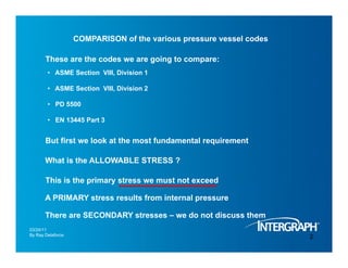
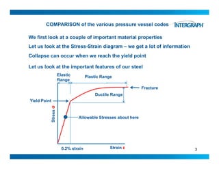
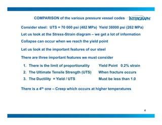
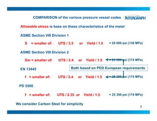
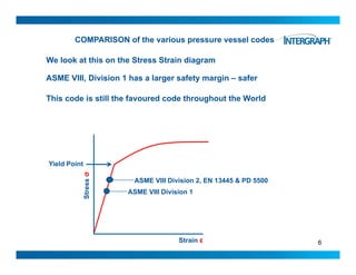
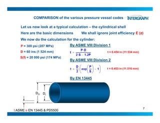
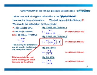
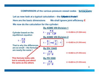
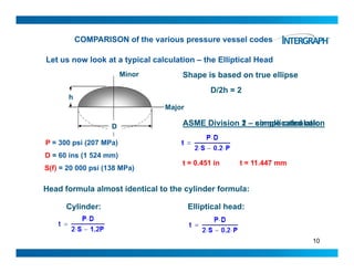
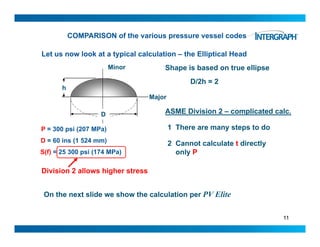
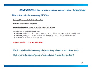
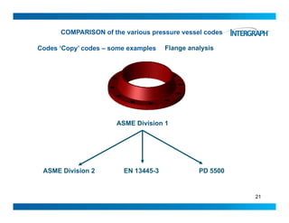
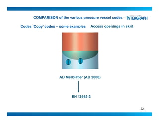
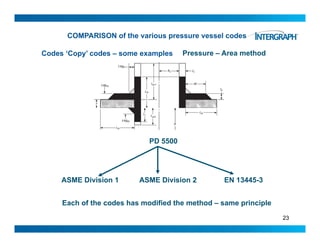
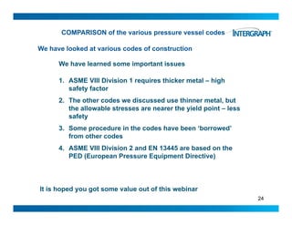
The document compares several pressure vessel codes and how they differ in calculating allowable stresses and vessel wall thicknesses. It finds that ASME Section VIII Division 1 is the most conservative with the highest safety factor, while the other codes allow for slightly higher stresses near the material's yield point. The codes also sometimes borrow procedures from one another, like using similar formulas for vessel heads. Overall, the document aims to explain the approaches in codes like ASME, EN, and PD5500 and how they both differ and align in designing pressure vessels.
Design by Analysis - A general guideline for pressure vesselAnalyzeForSafety
This presentation file is provided by Mr. Ghanbari and published under permission.
The presentation gives an introduction and general guideline for pressure vessel design by analysis.
The “design by analysis” procedures are intended to guard against eight possible pressure vessel failure modes by performing a detailed stress analysis of the vessel with the sufficient design factors. The failure modes are:
1.excessive elastic deformation, including elastic instability,
2.excessive plastic deformation,
3.brittle fracture,
4.stress rupture/creep deformation (inelastic),
5.plastic instability - incremental collapse,
6.high strain - low cycle fatigue,
7.stress corrosion, and
8.corrosion fatigue
Most of the “design by analysis” procedures that are given in ASME BPVC relate to designs based on “elastic analysis.”
The design-by-analysis requirements are organized based on protection against the failure modes listed below. The component shall be evaluated for each applicable failure mode. If multiple assessment procedures are provided for a failure mode, only one of these procedures must be satisfied to qualify the design of a component.
a)All pressure vessels within the scope of this Division, irrespective of size or pressure, shall be provided with protection against overpressure in accordance with the requirements of this Part.
b)Protection Against Plastic Collapse – these requirements apply to all components where the thickness and configuration of the component is established using design-by-analysis rules.
c)Protection Against Local Failure – these requirements apply to all components where the thickness and configuration of the component is established using design-by-analysis rules. It is not necessary to evaluate the local strain limit criterion if the component design is in accordance with Part 4 (i.e. component wall thickness and weld detail per paragraph 4.2).
d)Protection Against Collapse From Buckling – these requirements apply to all components where the thickness and configuration of the component is established using design-by-analysis rules and the applied loads result in a compressive stress field.
e)Protection Against Failure From Cyclic Loading – these requirements apply to all components where the thickness and configuration of the component is established using design-by-analysis rules and the applied loads are cyclic. In addition, these requirements can also be used to qualify a component for cyclic loading where the thickness and size of the component are established using the design-by-rule requirements of Part 4.
Static and Fatigue Analysis of Pressure Vessel as per ASME CodesUtsav Patel
The problem statement is to design a pressure vessel working as an adsorber in a chemical plant. Design data calculated as per ASME BPVC Section VIII/Division I and it analyzed as per ASME BPVC Section VIII/Division II. You can trust this data.
If you need any help regarding this, contact me via LinkedIn.
This power point was prepared for the course named as Chemical Engineering Apparatus Design. Target group was 4th year chemical engineering Students for the first semester
This is in continuation to my previous post (walk through-piping).
Generally, when we talk about Pipe stress analysis basics, we tend to quickly jump to Failure theories, B31.3, Caesar II, Static & Dynamic, offshore /onshore, jacketed piping etc.
Walk through Pipe stress is to ease into piping stress world with its polite introduction to curious techies, without having hold on Forces/moments/displacement equations.
Pipe Stress Analysis Basics will be taken next.
regards
Ashish
Gems specializes in made-to-order fluidic systems, and a major segment of that
activity includes the integration of miniature solenoid valves and manifold assemblies.
Our miniature and subminiature solenoid valves are utilized in solutions that serve
industries ranging from medical and biotech to automotive and industrial equipment.
One day training program to give insights of materials
Very informative for fabricators, design engineers, welding engineers and others dealing in material
Welcome to WIPAC Monthly the magazine brought to you by the LinkedIn Group Water Industry Process Automation & Control.
In this month's edition, along with this month's industry news to celebrate the 13 years since the group was created we have articles including
A case study of the used of Advanced Process Control at the Wastewater Treatment works at Lleida in Spain
A look back on an article on smart wastewater networks in order to see how the industry has measured up in the interim around the adoption of Digital Transformation in the Water Industry.
Water scarcity is the lack of fresh water resources to meet the standard water demand. There are two type of water scarcity. One is physical. The other is economic water scarcity.
Sachpazis:Terzaghi Bearing Capacity Estimation in simple terms with Calculati...Dr.Costas Sachpazis
Terzaghi's soil bearing capacity theory, developed by Karl Terzaghi, is a fundamental principle in geotechnical engineering used to determine the bearing capacity of shallow foundations. This theory provides a method to calculate the ultimate bearing capacity of soil, which is the maximum load per unit area that the soil can support without undergoing shear failure. The Calculation HTML Code included.
Industrial Training at Shahjalal Fertilizer Company Limited (SFCL)MdTanvirMahtab2
This presentation is about the working procedure of Shahjalal Fertilizer Company Limited (SFCL). A Govt. owned Company of Bangladesh Chemical Industries Corporation under Ministry of Industries.
COLLEGE BUS MANAGEMENT SYSTEM PROJECT REPORT.pdfKamal Acharya
The College Bus Management system is completely developed by Visual Basic .NET Version. The application is connect with most secured database language MS SQL Server. The application is develop by using best combination of front-end and back-end languages. The application is totally design like flat user interface. This flat user interface is more attractive user interface in 2017. The application is gives more important to the system functionality. The application is to manage the student’s details, driver’s details, bus details, bus route details, bus fees details and more. The application has only one unit for admin. The admin can manage the entire application. The admin can login into the application by using username and password of the admin. The application is develop for big and small colleges. It is more user friendly for non-computer person. Even they can easily learn how to manage the application within hours. The application is more secure by the admin. The system will give an effective output for the VB.Net and SQL Server given as input to the system. The compiled java program given as input to the system, after scanning the program will generate different reports. The application generates the report for users. The admin can view and download the report of the data. The application deliver the excel format reports. Because, excel formatted reports is very easy to understand the income and expense of the college bus. This application is mainly develop for windows operating system users. In 2017, 73% of people enterprises are using windows operating system. So the application will easily install for all the windows operating system users. The application-developed size is very low. The application consumes very low space in disk. Therefore, the user can allocate very minimum local disk space for this application.
Quality defects in TMT Bars, Possible causes and Potential Solutions.PrashantGoswami42
Maintaining high-quality standards in the production of TMT bars is crucial for ensuring structural integrity in construction. Addressing common defects through careful monitoring, standardized processes, and advanced technology can significantly improve the quality of TMT bars. Continuous training and adherence to quality control measures will also play a pivotal role in minimizing these defects.
Final project report on grocery store management system..pdfKamal Acharya
In today’s fast-changing business environment, it’s extremely important to be able to respond to client needs in the most effective and timely manner. If your customers wish to see your business online and have instant access to your products or services.
Online Grocery Store is an e-commerce website, which retails various grocery products. This project allows viewing various products available enables registered users to purchase desired products instantly using Paytm, UPI payment processor (Instant Pay) and also can place order by using Cash on Delivery (Pay Later) option. This project provides an easy access to Administrators and Managers to view orders placed using Pay Later and Instant Pay options.
In order to develop an e-commerce website, a number of Technologies must be studied and understood. These include multi-tiered architecture, server and client-side scripting techniques, implementation technologies, programming language (such as PHP, HTML, CSS, JavaScript) and MySQL relational databases. This is a project with the objective to develop a basic website where a consumer is provided with a shopping cart website and also to know about the technologies used to develop such a website.
This document will discuss each of the underlying technologies to create and implement an e- commerce website.
About
Indigenized remote control interface card suitable for MAFI system CCR equipment. Compatible for IDM8000 CCR. Backplane mounted serial and TCP/Ethernet communication module for CCR remote access. IDM 8000 CCR remote control on serial and TCP protocol.
• Remote control: Parallel or serial interface.
• Compatible with MAFI CCR system.
• Compatible with IDM8000 CCR.
• Compatible with Backplane mount serial communication.
• Compatible with commercial and Defence aviation CCR system.
• Remote control system for accessing CCR and allied system over serial or TCP.
• Indigenized local Support/presence in India.
• Easy in configuration using DIP switches.
Technical Specifications
Indigenized remote control interface card suitable for MAFI system CCR equipment. Compatible for IDM8000 CCR. Backplane mounted serial and TCP/Ethernet communication module for CCR remote access. IDM 8000 CCR remote control on serial and TCP protocol.
Key Features
Indigenized remote control interface card suitable for MAFI system CCR equipment. Compatible for IDM8000 CCR. Backplane mounted serial and TCP/Ethernet communication module for CCR remote access. IDM 8000 CCR remote control on serial and TCP protocol.
• Remote control: Parallel or serial interface
• Compatible with MAFI CCR system
• Copatiable with IDM8000 CCR
• Compatible with Backplane mount serial communication.
• Compatible with commercial and Defence aviation CCR system.
• Remote control system for accessing CCR and allied system over serial or TCP.
• Indigenized local Support/presence in India.
Application
• Remote control: Parallel or serial interface.
• Compatible with MAFI CCR system.
• Compatible with IDM8000 CCR.
• Compatible with Backplane mount serial communication.
• Compatible with commercial and Defence aviation CCR system.
• Remote control system for accessing CCR and allied system over serial or TCP.
• Indigenized local Support/presence in India.
• Easy in configuration using DIP switches.
Democratizing Fuzzing at Scale by Abhishek Aryaabh.arya
Presented at NUS: Fuzzing and Software Security Summer School 2024
This keynote talks about the democratization of fuzzing at scale, highlighting the collaboration between open source communities, academia, and industry to advance the field of fuzzing. It delves into the history of fuzzing, the development of scalable fuzzing platforms, and the empowerment of community-driven research. The talk will further discuss recent advancements leveraging AI/ML and offer insights into the future evolution of the fuzzing landscape.
Automobile Management System Project Report.pdfKamal Acharya
The proposed project is developed to manage the automobile in the automobile dealer company. The main module in this project is login, automobile management, customer management, sales, complaints and reports. The first module is the login. The automobile showroom owner should login to the project for usage. The username and password are verified and if it is correct, next form opens. If the username and password are not correct, it shows the error message.
When a customer search for a automobile, if the automobile is available, they will be taken to a page that shows the details of the automobile including automobile name, automobile ID, quantity, price etc. “Automobile Management System” is useful for maintaining automobiles, customers effectively and hence helps for establishing good relation between customer and automobile organization. It contains various customized modules for effectively maintaining automobiles and stock information accurately and safely.
When the automobile is sold to the customer, stock will be reduced automatically. When a new purchase is made, stock will be increased automatically. While selecting automobiles for sale, the proposed software will automatically check for total number of available stock of that particular item, if the total stock of that particular item is less than 5, software will notify the user to purchase the particular item.
Also when the user tries to sale items which are not in stock, the system will prompt the user that the stock is not enough. Customers of this system can search for a automobile; can purchase a automobile easily by selecting fast. On the other hand the stock of automobiles can be maintained perfectly by the automobile shop manager overcoming the drawbacks of existing system.
1. Comparison of pressure vessel codes
Why do the codes differ and How do they differ
Presented by: Ray Delaforce
3/24/2011 By Ray Delaforce
03/24/11
By Ray Delaforce
2. COMPARISON of the various pressure vessel codes
These are the codes we are going to compare:
• ASME Section VIII, Division 1
• ASME Section VIII, Division 2
• PD 5500
• EN 13445 Part 3
But first we look at the most fundamental requirement
What is the ALLOWABLE STRESS ?
This is the primary stress we must not exceedy
A PRIMARY stress results from internal pressure
There are SECONDARY stresses – we do not discuss them
3/24/2011 By Ray Delaforce
03/24/11
By Ray Delaforce
2
3. COMPARISON of the various pressure vessel codes
We first look at a couple of important material properties
Let us look at the Stress-Strain diagram – we get a lot of information
El ti
Collapse can occur when we reach the yield point
Let us look at the important features of our steel
Elastic
Range
Plastic Range
Fracture
Ductile Range
essσ
Yield Point
Ductile Range
All bl St b t h
Stre
Allowable Stresses about here
3Strain ε0.2% strain
4. COMPARISON of the various pressure vessel codes
Let us look at the Stress-Strain diagram – we get a lot of information
Consider steel: UTS = 70 000 psi (482 MPa) Yield 38000 psi (262 MPa)
Collapse can occur when we reach the yield point
Let us look at the important features of our steel
There are three important features we must consider
1. There is the limit of proportionality Yield Point 0.2% strain
2. The Ultimate Tensile Strength (UTS) When fracture occurs
3. The Ductility = Yield / UTS Must be less than 1.0
There is a 4th one – Creep which occurs at higher temperatures
4
5. COMPARISON of the various pressure vessel codes
Allowable stress is base on these characteristics of the metal
ASME Section VIII Division 1
ASME Section VIII Division 2
S = smaller of: UTS / 3.5 or Yield / 1.5 = 20 000 psi (138 MPa)
ASME Section VIII Division 2
EN 13445
Sm = smaller of: UTS / 2.4 or Yield / 1.5
Both based on PED European requirements
= 25 300 psi (174 MPa)
EN 13445
f = smaller of: UTS / 2.4 or Yield / 1.5
Both based on PED European requirements
= 25 300 psi (174 MPa)
PD 5500
f = smaller of: UTS / 2.35 or Yield / 1.5 = 25 300 psi (174 MPa)
5
We consider Carbon Steel for simplicity
6. COMPARISON of the various pressure vessel codes
We look at this on the Stress Strain diagram
ASME VIII, Division 1 has a larger safety margin – safer
This code is still the favoured code throughout the World
essσ
Yield Point
ASME VIII Di i i 1
ASME VIII Division 2, EN 13445 & PD 5500
Stre
ASME VIII Division 1
Strain ε 6
7. COMPARISON of the various pressure vessel codes
Let us now look at a typical calculation – the cylindrical shell
Here are the basic dimensions We shall ignore joint efficiency E (z)
W d th l l ti f th li d
P = 300 psi (207 MPa)
D = 60 ins (1 524 mm)
We now do the calculation for the cylinder:
t = 0.454 in (11.534 mm)
By ASME VIII Division 1
S(f) = 20 000 psi (174 MPa)
By ASME VIII Division 2
t = 0.453 in (11.516 mm)t 0.453 in (11.516 mm)
By EN 13445
DO Di
7
t ASME e EN 13445 & PD5500
8. COMPARISON of the various pressure vessel codes
Let us now look at a typical calculation – the cylindrical shell
Here are the basic dimensions We shall ignore joint efficiency E
W d th l l ti f th li d
Let us now look at a typical calculation – the Elliptical Head
P = 300 psi (207 MPa)
D = 60 ins (1 524 mm)
We now do the calculation for the cylinder:
t = 0.454 in (11.534 mm)
By ASME VIII Division 1
S(f) = 20 000 psi (174 MPa)
By ASME VIII Division 2
t = 0.453 in (11.516 mm)t 0.453 in (11.516 mm)
By EN 13445
t 0 453 i (11 516 )
That is why the differences
are so small – the formulae
are nearly the same !
t = 0.453 in (11.516 mm)
By PD 5500
t = 0 453 in (11 516 mm)
This formula looks odd,
but is actually just about
8
t = 0.453 in (11.516 mm)the same as the others
9. COMPARISON of the various pressure vessel codes
Let us now look at a typical calculation – the cylindrical shell
Here are the basic dimensions We shall ignore joint efficiency E
W d th l l ti f th li d
Let us now look at a typical calculation – the Elliptical Head
We now do the calculation for the cylinder:
t = 0.454 in (11.534 mm)
By ASME VIII Division 1
Cylinder based on the
By ASME VIII Division 2
t = 0.453 in (11.516 mm)
Cylinder based on the
equilibrium equation
t 0.453 in (11.516 mm)
By EN 13445
t 0 453 i (11 516 )
That is why the differences
are so small – the formulae
are nearly the same !
t = 0.453 in (11.516 mm)
By PD 5500
t = 0 453 in (11 516 mm)
This formula looks odd,
but is actually just about
9
t = 0.453 in (11.516 mm)the same as the others
10. COMPARISON of the various pressure vessel codes
Let us now look at a typical calculation – the Elliptical Head
Minor Shape is based on true ellipse
Major
h
D/2h = 2
P = 300 psi (207 MPa)
D 60 i (1 524 )
D ASME Division 1 – simple calculationASME Division 2 – complicated calc.
D = 60 ins (1 524 mm)
S(f) = 20 000 psi (138 MPa)
t = 0.451 in t = 11.447 mm
Head formula almost identical to the cylinder formula:Head formula almost identical to the cylinder formula:
Elliptical head:Cylinder:
10
11. COMPARISON of the various pressure vessel codes
Let us now look at a typical calculation – the Elliptical Head
Minor Shape is based on true ellipse
Major
h
D/2h = 2
P = 300 psi (207 MPa)
D 60 i (1 524 )
D ASME Division 2 – complicated calc.
1 There are many steps to do
D = 60 ins (1 524 mm)
S(f) = 25 300 psi (174 MPa)
2 Cannot calculate t directly . .
. only P
Division 2 allows higher stress
On the next slide we show the calculation per PV Elite
Division 2 allows higher stress
11
12. COMPARISON of the various pressure vessel codes
This is the calculation using PV Elite - ASME Division 2
The Elliptical head is transformed in equivalent Torispherical Head
12
Crown radius
Knuckle radius
13. COMPARISON of the various pressure vessel codes
This is the calculation using PV Elite - ASME Division 2
Next we must calculate some geometry factors
13
14. COMPARISON of the various pressure vessel codes
This is the calculation using PV Elite - ASME Division 2
Even more geometry and other factors………Even more geometry and other factors and more – lots of factors
14
15. COMPARISON of the various pressure vessel codes
This is the calculation using PV Elite - ASME Division 2
Even more geometry and other factors and more – lots of factors
Finally we end up with our starting pressure
15
PV Elite does an iterative calculation to end up with the pressure
Finally we end up with our starting pressure
16. COMPARISON of the various pressure vessel codes
This is the calculation using PV Elite - ASME Division 2
We had to start the calculate with a ‘guess’ thickness t
And we ended up with our starting pressure
We have to use a computer to do this calculation !
The computed thickness is t = 0.3219 in t = 8.1767 mm
16
17. COMPARISON of the various pressure vessel codes
This is the calculation using PV Elite - ASME Division 2
EN 13445 has a similar method – slightly less complicated than ASME
The final computed thickness is: t = 0.3886 in t = 9.8619 mm
17
18. COMPARISON of the various pressure vessel codes
The method of computing the head by PD 5500 is very different
Minor 1 Calculate h / D = 0.25
Major
h 2 Calculate P / f = 0.119
P = 300 psi (207 MPa)
D 60 i (1 524 )
D
D = 60 ins (1 524 mm)
f = 25 300 psi (174 MPa)
PD 5500 uses a graphical solutions – like this
18
19. COMPARISON of the various pressure vessel codes
Here is the Graph used to compute this head thickness
1 Calculate h / D = 0.25
2 Calculate P / f = 0.119
e / D
e = D x (e/D)
19
20. COMPARISON of the various pressure vessel codes
This is the calculation using PV Elite
t = 0.3792 in t = 9.6317 mm
Each code has its own way of computing a head – and other parts
But, where do codes ‘borrow’ procedures from other codes ?
20
21. COMPARISON of the various pressure vessel codes
Codes ‘Copy’ codes – some examples Flange analysis
ASME Division 1
ASME Division 2 EN 13445-3 PD 5500
21
22. COMPARISON of the various pressure vessel codes
Codes ‘Copy’ codes – some examples Access openings in skirt
AD Merblatter (AD 2000)
EN 13445-3
22
23. COMPARISON of the various pressure vessel codes
Codes ‘Copy’ codes – some examples Pressure – Area method
PD 5500PD 5500
ASME Division 1 ASME Division 2 EN 13445-3
E h f th d h difi d th th d i i l
23
Each of the codes has modified the method – same principle
24. COMPARISON of the various pressure vessel codes
We have looked at various codes of construction
We have learned some important issues
1. ASME VIII Division 1 requires thicker metal – high
safety factor
2 Th th d di d thi t l b t2. The other codes we discussed use thinner metal, but
the allowable stresses are nearer the yield point – less
safety
3 S d i th d h b ‘b d’3. Some procedure in the codes have been ‘borrowed’
from other codes
4. ASME VIII Division 2 and EN 13445 are based on the
PED (European Pressure Equipment Directive)PED (European Pressure Equipment Directive)
24
It is hoped you got some value out of this webinar