
Recommended
Recommended
More Related Content
What's hot
What's hot (20)
Similar to Cognex In-Sight - PROFINET Communications.pdf
Similar to Cognex In-Sight - PROFINET Communications.pdf (20)
Recently uploaded
Recently uploaded (20)
Cognex In-Sight - PROFINET Communications.pdf
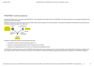
- 1. 26/05/2023, 06:59 In-Sight® Explorer Help - PROFINET Communications - Documentation | Cognex https://support.cognex.com/docs/is_574/web/EN/ise/Content/Communications_Reference/ProfiNET_Communications.htm?tocpath=Communications Reference%7CPROFINET Communications%7C_____0 1/2 PROFINET Communications Distributed I/O (Remote I/O) is connected through PROFINET IO. In this configuration, which retains the I/O view of PROFIBUS, user data from field devices are periodically transmitted into the process model of the control system. PROFINET IO describes a device model, which consists of insertion places (slots) and groups of I/O channels (subslots). The technical characteristics of the field devices are described by the GSD (General Station Description) on an XML basis. PROFINET IO distinguishes between the three following device types: IO-Controller: Controller on which the automation program is run. IO-Device: A remotely assigned field device, which is assigned to an IO-Controller. IO-Supervisor: A programming device (PC), which runs commissioning and diagnostic functions. The PROFINET IO engineering process is similar to PROFIBUS: Decentralized field buses are assigned to one or more control systems during configuration; the IO-Device is configured to the actual system expansion, based on the content in the GSD file; and the IO-Device is simultaneously integrated, appropriately parameterized and configured into the PROFINET topology (1).
- 2. 26/05/2023, 06:59 In-Sight® Explorer Help - PROFINET Communications - Documentation | Cognex https://support.cognex.com/docs/is_574/web/EN/ise/Content/Communications_Reference/ProfiNET_Communications.htm?tocpath=Communications Reference%7CPROFINET Communications%7C_____0 2/2 After the engineering process has been completed, the expansion data is loaded into the IO-Controller (2). The IO-Controller independently takes over the data exchange with the IO-Device (3). The In-Sight system supports PROFINET IO connections from two controllers (or supervisors) at any given time. The steps provided below describe how to use PROFINET IO to transfer data between In-Sight vision systems and a Siemens PLC. Copyright © 1999 - 2019 | Cognex Corporation | All Rights Reserved. In-Sight® Explorer Help | 2019 August 24 | Revision: 5.7.4.3
- 3. 26/05/2023, 06:35 In-Sight® Explorer Help - PROFINET Communications with an In-Sight Vision System - Documentation | Cognex https://support.cognex.com/docs/is_574/web/EN/ise/Content/Communications_Reference/PROFINET_Comms_PLCConnection.htm?tocpath=Communications Reference%7CPROFINET Communications%7CPROF… 1/1 PROFINET Communications with an In-Sight Vision System This section describes how to connect a Siemens PLC to an In-Sight vision system, using PROFINET IO communications. PROFINET IO allows an In-Sight vision system's inputs and outputs to be mapped into process memory in the Siemens PLC. Once these values have been established, they are synchronized at an interval defined by the update rate of the PROFINET IO system. The examples in this section were written assuming that you are using the following components: Siemens S7-300 or S7-400 series PLC with PROFINET option Siemens Step 7 programming software, version 5.3 with SP3 or newer The steps for configuring the connection depend on the In-Sight firmware version running on the In-Sight vision system. For more information, see Transferring Data With an In-Sight Vision System via PROFINET - In-Sight 4.x.x Firmware or Transferring Data With an In-Sight Vision System via PROFINET - In-Sight 5.x.x Firmware. Transferring Data with an In-Sight Vision System via PROFINET - In-Sight 4.x.x Firmware Transferring Data with an In-Sight Vision System via PROFINET - In-Sight 5.x.x Firmware Job Load by Name Using PROFINET IO Module Copyright © 1999 - 2019 | Cognex Corporation | All Rights Reserved. In-Sight® Explorer Help | 2019 August 24 | Revision: 5.7.4.3
- 4. 26/05/2023, 06:36 In-Sight® Explorer Help - Transferring Data With an In-Sight Vision System via PROFINET - In-Sight 4.x.x Firmware - Documentation | Cognex https://support.cognex.com/docs/is_574/web/EN/ise/Content/Communications_Reference/PROFINET_Comms_FW4x.htm?tocpath=Communications Reference%7CPROFINET Communications%7CPROFINET Co… 1/9 Transferring Data With an In-Sight Vision System via PROFINET - In-Sight 4.x.x Firmware This topic covers the transfer of data to and from an In-Sight vision system running In-Sight 4.x.x firmware, and a Siemens PLC. Enabling PROFINET Communications on an In-Sight Vision System Before PROFINET communications can be established with an In-Sight vision system, the vision system must be configured to enable PROFINET, using the Network Settings of the In-Sight vision system. 1. Open In-Sight Explorer and connect to an In-Sight vision system. 2. From the Sensor menu, open the Network Settings dialog. 3. In the Protocol Services section of the dialog, select PROFINET and press the Settings button to enable and configure the vision system's Station Name, as seen by the Siemens PLC, using the PROFINET Settings dialog. Note: If the Station Name is not set, the PLC will see the host name, which may not be identical to the vision system's host name, because the PROFINET protocol will translate characters it does not support to characters it does support. 4. Back in the Network Settings dialog, press OK. 5. Restart the In-Sight vision system, and the PROFINET service will be enabled upon completion of the power cycle. Setting Up the Connection To set up a PROFINET I/O connection between an In-Sight vision system and a Siemens controller, the In-Sight vision system must first be added to the controller's hardware configuration, using the Siemen's HW Config tool: 1. Open the SIMATIC manager and load the PLC's project.
- 5. 26/05/2023, 06:36 In-Sight® Explorer Help - Transferring Data With an In-Sight Vision System via PROFINET - In-Sight 4.x.x Firmware - Documentation | Cognex https://support.cognex.com/docs/is_574/web/EN/ise/Content/Communications_Reference/PROFINET_Comms_FW4x.htm?tocpath=Communications Reference%7CPROFINET Communications%7CPROFINET Co… 2/9 2. Select the SIMATIC 300 or SIMATIC 400 node, then double-click on the Hardware node in the object list. 3. The HW Config tool will now appear. In order to add PROFINET IO nodes to the controller, a PROFINET IO system must be present in the hardware configuration diagram; if there isn't a PROFINET IO system in the diagram, complete the following steps: Ensure that the PROFINET IO interface on the CPU has been assigned a subnet address; to verify this, double-click on the PROFINET IO module on the CPU. If the PROFINET IO module's Networked status indicates "No," then click the Properties button and add a new subnet. Once the PROFINET IO interface on the CPU has been assigned a subnet, add a PROFINET IO system to the hardware configuration diagram by right-clicking the PROFINET IO module in the PLC configuration and selecting Insert PROFINET IO System.
- 6. 26/05/2023, 06:36 In-Sight® Explorer Help - Transferring Data With an In-Sight Vision System via PROFINET - In-Sight 4.x.x Firmware - Documentation | Cognex https://support.cognex.com/docs/is_574/web/EN/ise/Content/Communications_Reference/PROFINET_Comms_FW4x.htm?tocpath=Communications Reference%7CPROFINET Communications%7CPROFINET Co… 3/9 4. If this is the first In-Sight vision system to be added to the PROFINET network, the In-Sight GSD file (version 2.3, provided by Cognex) will need to be installed. To install the In-Sight GSD file, follow these steps: From the HW Config tool, select Options > Install GSD Files from the menu. Press the Browse button and select the GSD folder from this location: C:Program Files (x86)CognexIn-SightIn-Sight Explorer 5.1.0Factory Protocol DescriptionGSD. Press the Select All button, then click the Install button to install the hardware description for the In-Sight vision systems. To add an In-Sight vision system to a PROFINET network, browse to the In-Sight node of the Hardware Catalog (PROFINET IO > Additional Field Devices > Sensors > Cognex Vision Sensors), and then drag an instance of the In-Sight vision system into the PROFINET IO System in the hardware configuration. 5. Set the device name to the exact name of the In-Sight vision system being connected to. Note: If an underscore was used in the In-Sight vision system's name, the underscore will have to be replaced by a hyphen when the vision system's name is input in PROFINET. For example, if the camera was named "Camera_Top" in In-Sight Explorer, it will need to be renamed to "Camera-Top" in PROFINET.
- 7. 26/05/2023, 06:36 In-Sight® Explorer Help - Transferring Data With an In-Sight Vision System via PROFINET - In-Sight 4.x.x Firmware - Documentation | Cognex https://support.cognex.com/docs/is_574/web/EN/ise/Content/Communications_Reference/PROFINET_Comms_FW4x.htm?tocpath=Communications Reference%7CPROFINET Communications%7CPROFINET Co… 4/9 6. The In-Sight vision system should now be displayed as a device on the PROFINET IO system, along with the In-Sight vision system's various modules supported by the particular PROFINET IO implementation. Note: Once the In-Sight vision system has been added as a device on the PROFINET IO system, to prevent the PLC from assigning the vision system a new IP address, disable the Assign IP address via IO controller checkbox in the vision system's Properties dialog. To open the Properties dialog and disable the checkbox (which is checked by default), either double-click the vision system device or right-click it and select Object Properties. If using Siemens Step 7 software to configure your PLC, click here. All of the available modules for the In-Sight vision system are automatically added to the hardware configuration. These modules allow access to the various subsystems in the In-Sight vision system. The default User Data and Inspection Results modules are 64 bytes in size. In order to change the sizes of the modules, delete them from the list and drag the
- 8. 26/05/2023, 06:36 In-Sight® Explorer Help - Transferring Data With an In-Sight Vision System via PROFINET - In-Sight 4.x.x Firmware - Documentation | Cognex https://support.cognex.com/docs/is_574/web/EN/ise/Content/Communications_Reference/PROFINET_Comms_FW4x.htm?tocpath=Communications Reference%7CPROFINET Communications%7CPROFINET Co… 5/9 appropriately sized module from under the In-Sight Data Modules folder in the Catalog tree to the Slot in the list. 7. Once the In-Sight vision system has been added to the PROFINET system in the HW Config utility, the cyclic transfer rate can be adjusted by opening the properties window of the PROFINET IO System. This can be done by double-clicking on the PROFINET IO System in the hardware configuration diagram. The cyclic update time can be set for the entire PROFINET IO System, or for each device, separately. Note: If the update time is left at the default value of 1 ms, a significant reduction in vision tool performance may be observed when the PLC is connected to an In-Sight vision system. This reduction can be alleviated by increasing the cyclic update time to either 8 ms or 16 ms. EXAMPLE: Setting Up a Connection This example assumes that an In-Sight vision system has been added as an input/output device in a Siemens project. After the project has been downloaded to the controller, cyclic data transfers will be initiated, at the requested update time. To verify a proper I/O connection, follow these steps: 1. While working Offline, perform the Siemens configuration steps, which were outlined in the Setting Up the Connection section. 2. Download the completed project to the Siemens controller and set the Operating Mode to Run. 3. Open the HW Config tool online. The In-Sight vision system should show no errors, which indicates that the I/O connection was completed successfully. 4. To verify the correct, 2-way transfer of I/O data between an In-Sight vision system and a Siemens controller, connect to the In-Sight vision system using In-Sight Explorer. From the In- Sight vision system's Spreadsheet View, open the AcquireImage property sheet and set the Trigger parameter to either External or Industrial Ethernet. Next, place the vision system Online.
- 9. 26/05/2023, 06:36 In-Sight® Explorer Help - Transferring Data With an In-Sight Vision System via PROFINET - In-Sight 4.x.x Firmware - Documentation | Cognex https://support.cognex.com/docs/is_574/web/EN/ise/Content/Communications_Reference/PROFINET_Comms_FW4x.htm?tocpath=Communications Reference%7CPROFINET Communications%7CPROFINET Co… 6/9 5. From the HW Config tool, with the In-Sight vision system selected, right-click on the Acquisition Control Module and select Monitor/Modify. 6. Next, change Input bit 0 from false to true; this enables the Acquisition Trigger Enable bit. 7. After this bit has been set, whenever Input bit 1 (Acquisition Trigger) is changed from false to true, the In-Sight vision system will acquire an image. 8. From the Monitor/Modify window of the Inspection Status module, if the Run conditionally checkbox is checked for Monitor, the Inspection Completed bit (Bit 1) can be observed changing state when the inspection completes by repeating step 7. Getting Data From an In-Sight Vision System In order to get data from the In-Sight Explorer spreadsheet on an In-Sight vision system running In-Sight 4.x.x firmware to a Siemens PLC, the data must be pushed into the PROFINET stack by using the WriteProfinetBuffer function. This function takes a buffer of data created by the FormatOutputBuffer function and writes the data to the inspection results area in the PROFINET Inspection Results module. This data is then transferred during the next update cycle. EXAMPLE: Getting Data From an In-Sight Vision System The following steps explain how to format the data that will be sent from an In-Sight vision system to a Siemens PLC.
- 10. 26/05/2023, 06:36 In-Sight® Explorer Help - Transferring Data With an In-Sight Vision System via PROFINET - In-Sight 4.x.x Firmware - Documentation | Cognex https://support.cognex.com/docs/is_574/web/EN/ise/Content/Communications_Reference/PROFINET_Comms_FW4x.htm?tocpath=Communications Reference%7CPROFINET Communications%7CPROFINET Co… 7/9 1. To begin, using In-Sight Explorer, create a new job. 2. From the Palette's Snippets tab, add these two Snippets to the spreadsheet: Acquisition > AcqCounter and Math & Logic > Random. 3. Open the AcquireImage cell and set the Trigger parameter to Continuous. 4. Right-click an empty cell and select Insert Function to open the Insert Function dialog. From the left pane, click on the Input/Output category, then double-click the FormatOutputBuffer function, from the right pane, to insert it into the spreadsheet. 5. The first 4 bytes of data will automatically be added to the PROFINET buffer, which will define the InspectionID and InspectionResultCode (as 16 bit integers), but these will not appear in the FormatOutputBuffer list 6. From the FormatOutputBuffer dialog, click on the Add button. This will initiate the cell selection mode; select the "Scaled random number" cell of the Random snippet. 7. From the FormatOutputBuffer dialog, click on the Add button again. This will initiate the cell selection mode; select the count cell of the AcqCounter snippet. 8. Close the FormatOutputBuffer dialog by clicking the OK button. 9. Right-click an empty cell and select Insert Function to open the Insert Function dialog. From the left pane, click on the Input/Output category, then double-click the WriteProfinetBuffer function, from the right pane, to insert it into the spreadsheet. 10. Set the WriteProfinetBuffer function's Buffer parameter as a cell reference to the recently created FormatOutputBuffer function's Buffer data structure. 11. Place the In-Sight vision system Online. 12. In the Simatic Manager, create a new Variable Table by right-clicking on your PLC and selecting Variable Table from the Insert New Object menu. Open the new Variable Table.
- 11. 26/05/2023, 06:36 In-Sight® Explorer Help - Transferring Data With an In-Sight Vision System via PROFINET - In-Sight 4.x.x Firmware - Documentation | Cognex https://support.cognex.com/docs/is_574/web/EN/ise/Content/Communications_Reference/PROFINET_Comms_FW4x.htm?tocpath=Communications Reference%7CPROFINET Communications%7CPROFINET Co… 8/9 13. Add two items to the table. Offset Address Display Format Description 0 PID 257 FLOATING_POINT Random Number +4 PID 261 DEC Acquisition ID Note: The addresses assume that the Inspection Results Module is at input address 253 (the first four bytes of the module are for the Inspection ID and Inspection Result Code). If the Inspection Results Module is at a different address, apply the specified offset to the input address to set the correct address. 14. In the Simatic Manager, open Configured PLC from the PLC > Connect To menu, and then select Monitor from the Variable menu; the values displayed should be identical to those displayed in the In-Sight Explorer spreadsheet. Sending Data to an In-Sight Vision System In order to send data from the Siemens PLC to the In-Sight Explorer spreadsheet, the data must be pulled from the PROFINET stack by using the ReadProfinetBuffer function. This function takes the data format created within the FormatInputBuffer function, reads the data from the data area of the PROFINET User Data module, and formats this data into the In-Sight Explorer spreadsheet. This data will be received from the PLC every update cycle. EXAMPLE: Sending Data to an In-Sight Vision System For this example, create a new job within In-Sight Explorer and then perform the following steps to configure the data that will be received by the Siemens PLC. 1. Open the AcquireImage cell and set the Trigger parameter to Continuous. 2. Right-click an empty cell and select Insert Function to open the Insert Function dialog. From the left pane, click on the Input/Output category, then double-click the FormatInputBuffer function, from the right pane, to insert it into the spreadsheet. 3. From the FormatInputBuffer dialog, click on the Add button and add a 32-bit float and a 32-bit integer to the list. 4. Close the FormatInputBuffer dialog by clicking the OK button.
- 12. 26/05/2023, 06:36 In-Sight® Explorer Help - Transferring Data With an In-Sight Vision System via PROFINET - In-Sight 4.x.x Firmware - Documentation | Cognex https://support.cognex.com/docs/is_574/web/EN/ise/Content/Communications_Reference/PROFINET_Comms_FW4x.htm?tocpath=Communications Reference%7CPROFINET Communications%7CPROFINET Co… 9/9 5. Right-click an empty cell and select Insert Function to open the Insert Function dialog. From the left pane, click on the Input/Output category, then double-click the ReadProfinetBuffer function, from the right pane, to insert it into the spreadsheet . 6. Set the ReadProfinetBuffer function's Buffer parameter as a cell reference to the recently created FormatInputBuffer function's Buffer data structure. 7. The Vision Data Access functions will automatically be added to the spreadsheet based on the fields added to the FormatInputBuffer function. 8. Place the In-Sight vision system Online. 9. In the Simatic Manager, create a new Variable Table by right-clicking on your PLC and selecting Variable Table from theInsert New Object menu. Open the new Variable Table. 10. Add two items to the table. Offset Address Display Format 0 PQD 257 FLOATING_POINT +4 PQD 261 DEC Note: The addresses assume that the User Data Module is at output address 257. If the User Data Module is at a different address, apply the specified offset to the output address to set the correct address. 11. In the Simatic Manager, click on the PLC > Connect To > Configured PLC menu. 12. Enter values for the two items added to the Variable Table and then select the Activate Modify Values from the Variable menu. 13. The values in the In-Sight Explorer spreadsheet should change to the entered values. Copyright © 1999 - 2019 | Cognex Corporation | All Rights Reserved. In-Sight® Explorer Help | 2019 August 24 | Revision: 5.7.4.3
- 13. 26/05/2023, 06:36 In-Sight® Explorer Help - Transferring Data With an In-Sight Vision System via PROFINET - In-Sight 5.x.x Firmware - Documentation | Cognex https://support.cognex.com/docs/is_574/web/EN/ise/Content/Communications_Reference/PROFINET_Comms_FW5x.htm?tocpath=Communications Reference%7CPROFINET Communications%7CPROFINET Co… 1/9 Transferring Data With an In-Sight Vision System via PROFINET - In-Sight 5.x.x Firmware This topic covers the transfer of data to and from an In-Sight vision system running In-Sight 5.1.0 and later firmware, and a Siemens PLC. Enabling PROFINET Communications on an In-Sight Vision System Before PROFINET communications can be established with an In-Sight vision system, the vision system must be configured to enable PROFINET , using the Network Settings of the In-Sight vision system. 1. Open In-Sight Explorer and connect to an In-Sight vision system. 2. From the Sensor menu, open the Network Settings dialog. 3. In the Protocol Services section of the dialog, select PROFINET and press the Settings button to enable and configure the vision system's Station Name, as seen by the Siemens PLC, using the PROFINET Settings dialog. Note: If the Station Name is not set, the PLC will see the host name, which may not be identical to the vision system's host name, because the PROFINET protocol will translate characters it does not support to characters it does support. 4. Back in the Network Settings dialog, press OK. 5. Restart the In-Sight vision system, and the PROFINET service will be enabled upon completion of the power cycle. Setting Up the Connection To set up a PROFINET I/O connection between an In-Sight vision system and a Siemens controller, the In-Sight vision system must first be added to the controller's hardware configuration, using the Siemen's HW Config tool: 1. Open the SIMATIC manager and load the PLC's project.
- 14. 26/05/2023, 06:36 In-Sight® Explorer Help - Transferring Data With an In-Sight Vision System via PROFINET - In-Sight 5.x.x Firmware - Documentation | Cognex https://support.cognex.com/docs/is_574/web/EN/ise/Content/Communications_Reference/PROFINET_Comms_FW5x.htm?tocpath=Communications Reference%7CPROFINET Communications%7CPROFINET Co… 2/9 2. Select the SIMATIC 300 or SIMATIC 400 node, then double-click on the Hardware node in the object list. 3. The HW Config tool will now appear. In order to add PROFINET IO nodes to the controller, a PROFINET IO system must be present in the hardware configuration diagram; if there isn't a PROFINET IO system in the diagram, complete the following steps: Ensure that the PROFINET IO interface on the CPU has been assigned a subnet address; to verify this, double-click on the PROFINET IO module on the CPU. If the PROFINET IO module's Networked status indicates "No," then click the Properties button and add a new subnet. Once the PROFINET IO interface on the CPU has been assigned a subnet, add a PROFINET IO system to the hardware configuration diagram by right-clicking the PROFINET IO module in the PLC configuration and selecting Insert PROFINET IO System.
- 15. 26/05/2023, 06:36 In-Sight® Explorer Help - Transferring Data With an In-Sight Vision System via PROFINET - In-Sight 5.x.x Firmware - Documentation | Cognex https://support.cognex.com/docs/is_574/web/EN/ise/Content/Communications_Reference/PROFINET_Comms_FW5x.htm?tocpath=Communications Reference%7CPROFINET Communications%7CPROFINET Co… 3/9 4. If this is the first In-Sight vision system to be added to the PROFINET network, the In-Sight GSD file (version 2.3, provided by Cognex) will need to be installed. To install the In-Sight GSD file, follow these steps: From the HW Config tool, select Options > Install GSD Files from the menu. Press the Browse button and select the GSD folder from this location: C:Program Files (x86)CognexIn-SightIn-Sight Explorer 5.1.0Factory Protocol DescriptionGSD. Press the Select All button, then click the Install button to install the hardware description for the In-Sight vision systems. To add an In-Sight vision system to a PROFINET network, browse to the In-Sight node of the Hardware Catalog (PROFINET IO > Additional Field Devices > Sensors > Cognex Vision Sensors), and then drag an instance of the In-Sight vision system into the PROFINET IO System in the hardware configuration. 5. Set the device name to the exact name of the In-Sight vision system being connected to. Note: Make sure to select the device that reflects the In-Sight firmware that your system is running (for example, In-Sight 7xxx for 4.x.x firmware and In-Sight 79xx-75xx for 5.x.x firmware). Note: If an underscore was used in the In-Sight vision system's name, the underscore will have to be replaced by a hyphen when the vision system's name is input in PROFINET. For example, if the camera was named "Camera_Top" in In-Sight Explorer, it will need to be renamed to "Camera-Top" in PROFINET.
- 16. 26/05/2023, 06:36 In-Sight® Explorer Help - Transferring Data With an In-Sight Vision System via PROFINET - In-Sight 5.x.x Firmware - Documentation | Cognex https://support.cognex.com/docs/is_574/web/EN/ise/Content/Communications_Reference/PROFINET_Comms_FW5x.htm?tocpath=Communications Reference%7CPROFINET Communications%7CPROFINET Co… 4/9 6. The In-Sight vision system should now be displayed as a device on the PROFINET IO system, along with the In-Sight vision system's various modules supported by the particular PROFINET IO implementation. Note: Once the In-Sight vision system has been added as a device on the PROFINET IO system, to prevent the PLC from assigning the vision system a new IP address, disable the Assign IP address via IO controller checkbox in the vision system's Properties dialog. To open the Properties dialog and disable the checkbox (which is checked by default), either double-click the vision system device or right-click it and select Object Properties. If using Siemens Step 7 software to configure your PLC, click here. All of the available modules for the In-Sight vision system are automatically added to the hardware configuration. These modules allow access to the various subsystems in the In-Sight vision system. The default UserData and InspectionResults modules are 64 bytes in size. In order to change the sizes of the modules, delete them from the list and drag the appropriately sized module from under the In-Sight Data Modules folder in the Catalog tree to the Slot in the list.
- 17. 26/05/2023, 06:36 In-Sight® Explorer Help - Transferring Data With an In-Sight Vision System via PROFINET - In-Sight 5.x.x Firmware - Documentation | Cognex https://support.cognex.com/docs/is_574/web/EN/ise/Content/Communications_Reference/PROFINET_Comms_FW5x.htm?tocpath=Communications Reference%7CPROFINET Communications%7CPROFINET Co… 5/9 7. Once the In-Sight vision system has been added to the PROFINET system in the HW Config utility, the cyclic transfer rate can be adjusted. To adjust the rate, double-click the vision system and set the update time to a value in the range of 16 ms. If the update time is left at the default value of 1 ms, a significant reduction in vision tool performance may be observed when the PLC is connected to an In-Sight vision system. This reduction can be alleviated by increasing the cyclic update time to either 8 ms or 16 ms. EXAMPLE: Setting Up a Connection This example assumes that an In-Sight vision system has been added as an input/output device in a Siemens project. After the project has been downloaded to the controller, cyclic data transfers will be initiated, at the requested update time. To verify a proper I/O connection, follow these steps: 1. While working Offline, perform the Siemens configuration steps, which were outlined in the Setting Up the Connection section. 2. Download the completed project to the Siemens controller and set the Operating Mode to Run. 3. Open the HW Config tool online. The In-Sight vision system should show no errors, which indicates that the I/O connection was completed successfully. 4. To verify the correct, 2-way transfer of I/O data between an In-Sight vision system and a Siemens controller, connect to the In-Sight vision system using In-Sight Explorer. From the In- Sight vision system's Spreadsheet View, open the AcquireImage property sheet and set the Trigger parameter to either External or Industrial Ethernet. Next, place the vision system Online. 5. From the HW Config tool, with the In-Sight vision system selected, right-click on the Acquisition Control Module and select Monitor/Modify.
- 18. 26/05/2023, 06:36 In-Sight® Explorer Help - Transferring Data With an In-Sight Vision System via PROFINET - In-Sight 5.x.x Firmware - Documentation | Cognex https://support.cognex.com/docs/is_574/web/EN/ise/Content/Communications_Reference/PROFINET_Comms_FW5x.htm?tocpath=Communications Reference%7CPROFINET Communications%7CPROFINET Co… 6/9 6. Next, change Input bit 0 from false to true; this enables the Acquisition Trigger Enable bit. 7. After this bit has been set, whenever Input bit 1 (Acquisition Trigger) is changed from false to true, the In-Sight vision system will acquire an image. 8. From the Monitor/Modify window of the Inspection Status module, if the Run conditionally checkbox is checked for Monitor, the Inspection Completed bit (Bit 1) can be observed changing state when the inspection completes by repeating step 7. Getting Data From an In-Sight Vision System In order to get data from the In-Sight Explorer spreadsheet on an In-Sight vision system running In-Sight 5.1.0 and later firmware to a Siemens PLC, the data must be pushed into the PROFINET stack by using the WriteResultsBuffer function. This function takes a buffer of data created by the FormatOutputBuffer function and writes the data to the inspection results area in the PROFINET Inspection Results module. This data is then transferred during the next update cycle. EXAMPLE: Getting Data From an In-Sight Vision System The following steps explain how to format the data that will be sent from an In-Sight vision system to a Siemens PLC. 1. To begin, using In-Sight Explorer, create a new job. 2. From the Palette's Snippets tab, add these two Snippets to the spreadsheet: Acquisition > AcqCounter and Math & Logic > Random. 3. Open the AcquireImage cell and set the Trigger parameter to Continuous. 4. Right-click an empty cell and select Insert Function to open the Insert Function dialog. From the left pane, click on the Input/Output category, then double-click the FormatOutputBuffer function, from the right pane, to insert it into the spreadsheet. 5. The first 4 bytes of data will automatically be added to the PROFINET buffer, which will define the InspectionID and InspectionResultCode (as 16 bit integers), but these will not appear in the FormatOutputBuffer list. 6. From the FormatOutputBuffer dialog, click on the Add button. This will initiate the cell selection mode; select the "Scaled random number" cell of the Random snippet. 7. From the FormatOutputBuffer dialog, click on the Add button again. This will initiate the cell selection mode; select the count cell of the AcqCounter snippet. 8. Close the FormatOutputBuffer dialog by clicking the OK button. 9. Right-click an empty cell and select Insert Function to open the Insert Function dialog. From the left pane, click on the Input/Output category, then double-click the WriteResultsBuffer function, from the right pane, to insert it into the spreadsheet.
- 19. 26/05/2023, 06:36 In-Sight® Explorer Help - Transferring Data With an In-Sight Vision System via PROFINET - In-Sight 5.x.x Firmware - Documentation | Cognex https://support.cognex.com/docs/is_574/web/EN/ise/Content/Communications_Reference/PROFINET_Comms_FW5x.htm?tocpath=Communications Reference%7CPROFINET Communications%7CPROFINET Co… 7/9 10. Set the WriteResultsBuffer function's Protocol parameter to PROFINET, and the Buffer parameter as a cell reference to the recently created FormatOutputBuffer function's Buffer data structure. 11. Place the In-Sight vision system Online. 12. In the Simatic Manager, create a new Variable Table by right-clicking on your PLC and selecting Variable Table from the Insert New Object menu, and then open the new table. 13. Add four items to the table. Offset Address Display Format Description 0 PID 257 FLOATING_POINT Random Number +4 PID 261 DEC Acquisition ID Note: The addresses assume that the Inspection Results Module is at input address 253 (the first four bytes of the module are for the Inspection ID and Inspection Result Code). If the Inspection Results Module is at a different address, apply the specified offset to the input address to set the correct address. 14. In the Simatic Manager, open Configured PLC from the PLC > Connect To menu, and then select Monitor from the Variable menu; the values displayed should be identical to those displayed in the In-Sight Explorer spreadsheet. Sending Data to an In-Sight Vision System In order to send data from the Siemens PLC to the In-Sight Explorer spreadsheet, the data must be pulled from the PROFINET stack by using the ReadUserDataBuffer function. This function takes the data format created within the FormatInputBuffer function, reads the data from the data area of the PROFINET User Data module, and formats this data into the In-Sight Explorer spreadsheet. This data will be received from the PLC every update cycle. EXAMPLE: Sending Data to an In-Sight Vision System For this example, create a new job within In-Sight Explorer and then perform the following steps to configure the data that will be received by the Siemens PLC. 1. Open the AcquireImage cell and set the Trigger parameter to Continuous. 2. Right-click an empty cell and select Insert Function to open the Insert Function dialog. From the left pane, click on the Input/Output category, then double-click the FormatInputBuffer function, from the right pane, to insert it into the spreadsheet.
- 20. 26/05/2023, 06:36 In-Sight® Explorer Help - Transferring Data With an In-Sight Vision System via PROFINET - In-Sight 5.x.x Firmware - Documentation | Cognex https://support.cognex.com/docs/is_574/web/EN/ise/Content/Communications_Reference/PROFINET_Comms_FW5x.htm?tocpath=Communications Reference%7CPROFINET Communications%7CPROFINET Co… 8/9 3. From the FormatInputBuffer dialog, click on the Add button and add a 32-bit float and a 32-bit integer to the list. 4. Close the FormatInputBuffer dialog by clicking the OK button. 5. Right-click an empty cell and select Insert Function to open the Insert Function dialog. From the left pane, click on the Input/Output category, then double-click the ReadUserDataBuffer function, from the right pane, to insert it into the spreadsheet . 6. Set the ReadUserDataBuffer function's Protocol parameter to PROFINET, and the Buffer parameter as a cell reference to the recently created FormatInputBuffer function's Buffer data structure. 7. The Vision Data Access functions will automatically be added to the spreadsheet based on the fields added to the FormatInputBuffer function. 8. Place the In-Sight vision system Online. 9. In the Simatic Manager, create a new Variable Table by right-clicking on your PLC and selecting Variable Table from the Insert New Objectmenu, and then open the new table. 10. Add four items to the table, two for the sent user data, and the last two for SetUserData and SetUserDataAck: Offset Address Display Format 0 PQD 257 FLOATING_POINT +4 PQD 261 DEC Q1.2 BOOL I4.7 BOOL Note: The addresses assume that the User Data Module is at output address 257. If the User Data Module is at a different address, apply the specified offset to the output address to set the correct address. 11. In the Simatic Manager, click on the PLC > Connect To > Configured PLC menu. 12. Enter values for the four items added to the Variable Table and then select the Activate Modify Values from the Variable menu. 13. After entering the values, set the SetUserData bit, then wait for the SetUserDataAck bit to be set, and then clear the SetUserData bit. 14. The values in the In-Sight Explorer spreadsheet should change to the entered values.
- 21. 26/05/2023, 06:36 In-Sight® Explorer Help - Transferring Data With an In-Sight Vision System via PROFINET - In-Sight 5.x.x Firmware - Documentation | Cognex https://support.cognex.com/docs/is_574/web/EN/ise/Content/Communications_Reference/PROFINET_Comms_FW5x.htm?tocpath=Communications Reference%7CPROFINET Communications%7CPROFINET Co… 9/9 Copyright © 1999 - 2019 | Cognex Corporation | All Rights Reserved. In-Sight® Explorer Help | 2019 August 24 | Revision: 5.7.4.3
- 22. 26/05/2023, 06:36 In-Sight® Explorer Help - Job Load by Name Using PROFINET IO Module - Documentation | Cognex https://support.cognex.com/docs/is_574/web/EN/ise/Content/Communications_Reference/PROFINET_LoadJobbyName_5xx.htm?tocpath=Communications Reference%7CPROFINET Communications%7CPROFIN… 1/11 Job Load by Name Using PROFINET IO Module Note: The Job load by name feature is only available on In-Sight vision systems running In-Sight firmware 5.5.0 and later. For a complete list of models and supported firmware versions, see Firmware Versions.
- 23. 26/05/2023, 06:36 In-Sight® Explorer Help - Job Load by Name Using PROFINET IO Module - Documentation | Cognex https://support.cognex.com/docs/is_574/web/EN/ise/Content/Communications_Reference/PROFINET_LoadJobbyName_5xx.htm?tocpath=Communications Reference%7CPROFINET Communications%7CPROFIN… 2/11 1. Place the camera offline by setting the Set Offline bit high. Module ID Byte Bit 7 Bit 6 Bit 5 Bit 4 Bit 3 Bit 2 Bit 1 Bit 0 Acquisition Control 0x101 0 Set Offline Reserved Clear Exposure Complete Trigger Trigger Enable Acquisition Status 0x201 0 Online Offline Reason Missed Acq Exposure Complete Trigger Ack Trigger Ready 1..2 Acquisition ID Inspection Control 0x102 0 Clear Error Reserved Execute Command Set User Data Inspection Results Ack Buffer Results Enable Inspection Status 0x203 0 Set User Data Ack Command Failed Command Complete Command Executing Results Valid Results Buffer Overrun Inspection Completed System Busy 1 Error Reserved Reserved Job Pass 2..3 Error Code Command Control Input 0x107 0..1 Command (16-bit) Command Control Output 0x107 0..1 Current Job ID (16-bit) Soft Event Control Input 0x106 0 Soft Event 7 Soft Event 6 Soft Event 5 Soft Event 4 Soft Event 3 Soft Event 2 Soft Event 1 Soft Event 0 Soft Event Control Output 0x106 0 Soft Event Ack 7 Soft Event Ack 6 Soft Event Ack 5 Soft Event Ack 4 Soft Event Ack 3 Soft Event Ack 2 Soft Event Ack 1 Soft Event Ack 0 User Data 0x301(16) 0x302(32) 0x303(64) 0x304(128) 0x305(254) 0.. User Data
- 24. 26/05/2023, 06:36 In-Sight® Explorer Help - Job Load by Name Using PROFINET IO Module - Documentation | Cognex https://support.cognex.com/docs/is_574/web/EN/ise/Content/Communications_Reference/PROFINET_LoadJobbyName_5xx.htm?tocpath=Communications Reference%7CPROFINET Communications%7CPROFIN… 3/11 Module ID Byte Bit 7 Bit 6 Bit 5 Bit 4 Bit 3 Bit 2 Bit 1 Bit 0 Inspection Results 0x401(16) 0x402(32) 0x403(64) 0x404(128) 0x405(250) 0..1 Inspection ID 2..3 Inspection Results Code 4.. Inspection Results Acquisition Control Module Bit Name Description 7 Set Offline When this bit is set, the In-Sight vision system is taken Offline until the bit is cleared again.
- 25. 26/05/2023, 06:36 In-Sight® Explorer Help - Job Load by Name Using PROFINET IO Module - Documentation | Cognex https://support.cognex.com/docs/is_574/web/EN/ise/Content/Communications_Reference/PROFINET_LoadJobbyName_5xx.htm?tocpath=Communications Reference%7CPROFINET Communications%7CPROFIN… 4/11 2. Write the Job Load by Name command into bytes 0 and 1 of the Command Control Input Module. The Job Load by Name command is value 0x4000. Module ID Byte Bit 7 Bit 6 Bit 5 Bit 4 Bit 3 Bit 2 Bit 1 Bit 0 Acquisition Control 0x101 0 Set Offline Reserved Clear Exposure Complete Trigger Trigger Enable Acquisition Status 0x201 0 Online Offline Reason Missed Acq Exposure Complete Trigger Ack Trigger Ready 1..2 Acquisition ID Inspection Control 0x102 0 Clear Error Reserved Execute Command Set User Data Inspection Results Ack Buffer Results Enable Inspection Status 0x203 0 Set User Data Ack Command Failed Command Complete Command Executing Results Valid Results Buffer Overrun Inspection Completed System Busy 1 Error Reserved Reserved Job Pass 2..3 Error Code Command Control Input 0x107 0..1 Command (16-bit) Command Control Output 0x107 0..1 Current Job ID (16-bit) Soft Event Control Input 0x106 0 Soft Event 7 Soft Event 6 Soft Event 5 Soft Event 4 Soft Event 3 Soft Event 2 Soft Event 1 Soft Event 0 Soft Event Control Output 0x106 0 Soft Event Ack 7 Soft Event Ack 6 Soft Event Ack 5 Soft Event Ack 4 Soft Event Ack 3 Soft Event Ack 2 Soft Event Ack 1 Soft Event Ack 0 User Data 0x301(16) 0x302(32) 0x303(64) 0x304(128) 0x305(254) 0.. User Data
- 26. 26/05/2023, 06:36 In-Sight® Explorer Help - Job Load by Name Using PROFINET IO Module - Documentation | Cognex https://support.cognex.com/docs/is_574/web/EN/ise/Content/Communications_Reference/PROFINET_LoadJobbyName_5xx.htm?tocpath=Communications Reference%7CPROFINET Communications%7CPROFIN… 5/11 Module ID Byte Bit 7 Bit 6 Bit 5 Bit 4 Bit 3 Bit 2 Bit 1 Bit 0 Inspection Results 0x401(16) 0x402(32) 0x403(64) 0x404(128) 0x405(250) 0..1 Inspection ID 2..3 Inspection Results Code 4.. Inspection Results Command Control Input Module Byte Name Description 0 - 1 Command This is a 16-bit integer used to either indicate the Job ID number (0-999) of the job to load or to specify the Job Load by Name command (0x4000). The job load is executed when the Execute Command bit is set by the PLC. The Command field must be held constant between the rising edge of the Execute Command signal and the rising edge of the Command Completed signal, or the results will be indeterminate. If using the Job Load by Name command, the job name must be transferred to the User Data buffer before setting the Execute Command bit.
- 27. 26/05/2023, 06:36 In-Sight® Explorer Help - Job Load by Name Using PROFINET IO Module - Documentation | Cognex https://support.cognex.com/docs/is_574/web/EN/ise/Content/Communications_Reference/PROFINET_LoadJobbyName_5xx.htm?tocpath=Communications Reference%7CPROFINET Communications%7CPROFIN… 6/11 3. Write the job name to User Data Module. The job name must be null terminated (i.e. a 0 must be in the byte immediately following the job name). Module ID Byte Bit 7 Bit 6 Bit 5 Bit 4 Bit 3 Bit 2 Bit 1 Bit 0 Acquisition Control 0x101 0 Set Offline Reserved Clear Exposure Complete Trigger Trigger Enable Acquisition Status 0x201 0 Online Offline Reason Missed Acq Exposure Complete Trigger Ack Trigger Ready 1..2 Acquisition ID Inspection Control 0x102 0 Clear Error Reserved Execute Command Set User Data Inspection Results Ack Buffer Results Enable Inspection Status 0x203 0 Set User Data Ack Command Failed Command Complete Command Executing Results Valid Results Buffer Overrun Inspection Completed System Busy 1 Error Reserved Reserved Job Pass 2..3 Error Code Command Control Input 0x107 0..1 Command (16-bit) Command Control Output 0x107 0..1 Current Job ID (16-bit) Soft Event Control Input 0x106 0 Soft Event 7 Soft Event 6 Soft Event 5 Soft Event 4 Soft Event 3 Soft Event 2 Soft Event 1 Soft Event 0 Soft Event Control Output 0x106 0 Soft Event Ack 7 Soft Event Ack 6 Soft Event Ack 5 Soft Event Ack 4 Soft Event Ack 3 Soft Event Ack 2 Soft Event Ack 1 Soft Event Ack 0 User Data 0x301(16) 0x302(32) 0x303(64) 0x304(128) 0x305(254) 0.. User Data
- 28. 26/05/2023, 06:36 In-Sight® Explorer Help - Job Load by Name Using PROFINET IO Module - Documentation | Cognex https://support.cognex.com/docs/is_574/web/EN/ise/Content/Communications_Reference/PROFINET_LoadJobbyName_5xx.htm?tocpath=Communications Reference%7CPROFINET Communications%7CPROFIN… 7/11 Module ID Byte Bit 7 Bit 6 Bit 5 Bit 4 Bit 3 Bit 2 Bit 1 Bit 0 Inspection Results 0x401(16) 0x402(32) 0x403(64) 0x404(128) 0x405(250) 0..1 Inspection ID 2..3 Inspection Results Code 4.. Inspection Results
- 29. 26/05/2023, 06:36 In-Sight® Explorer Help - Job Load by Name Using PROFINET IO Module - Documentation | Cognex https://support.cognex.com/docs/is_574/web/EN/ise/Content/Communications_Reference/PROFINET_LoadJobbyName_5xx.htm?tocpath=Communications Reference%7CPROFINET Communications%7CPROFIN… 8/11 4. Set the Execute Command bit in the Inspection Control Module. Module ID Byte Bit 7 Bit 6 Bit 5 Bit 4 Bit 3 Bit 2 Bit 1 Bit 0 Acquisition Control 0x101 0 Set Offline Reserved Clear Exposure Complete Trigger Trigger Enable Acquisition Status 0x201 0 Online Offline Reason Missed Acq Exposure Complete Trigger Ack Trigger Ready 1..2 Acquisition ID Inspection Control 0x102 0 Clear Error Reserved Execute Command Set User Data Inspection Results Ack Buffer Results Enable Inspection Status 0x203 0 Set User Data Ack Command Failed Command Complete Command Executing Results Valid Results Buffer Overrun Inspection Completed System Busy 1 Error Reserved Reserved Job Pass 2..3 Error Code Command Control Input 0x107 0..1 Command (16-bit) Command Control Output 0x107 0..1 Current Job ID (16-bit) Soft Event Control Input 0x106 0 Soft Event 7 Soft Event 6 Soft Event 5 Soft Event 4 Soft Event 3 Soft Event 2 Soft Event 1 Soft Event 0 Soft Event Control Output 0x106 0 Soft Event Ack 7 Soft Event Ack 6 Soft Event Ack 5 Soft Event Ack 4 Soft Event Ack 3 Soft Event Ack 2 Soft Event Ack 1 Soft Event Ack 0 User Data 0x301(16) 0x302(32) 0x303(64) 0x304(128) 0x305(254) 0.. User Data
- 30. 26/05/2023, 06:36 In-Sight® Explorer Help - Job Load by Name Using PROFINET IO Module - Documentation | Cognex https://support.cognex.com/docs/is_574/web/EN/ise/Content/Communications_Reference/PROFINET_LoadJobbyName_5xx.htm?tocpath=Communications Reference%7CPROFINET Communications%7CPROFIN… 9/11 Module ID Byte Bit 7 Bit 6 Bit 5 Bit 4 Bit 3 Bit 2 Bit 1 Bit 0 Inspection Results 0x401(16) 0x402(32) 0x403(64) 0x404(128) 0x405(250) 0..1 Inspection ID 2..3 Inspection Results Code 4.. Inspection Results Inspection Control Module Bit Name Description 3 Execute Command When set, the vision system either loads the job ID specified in the Command field or executes the Job Load by Name command to load the job name given in the User Data buffer. The signal must be held high until the Command Completed signal is toggled. The falling edge of this signal (if prior to Command Complete) is interpreted as an abort request.
- 31. 26/05/2023, 06:36 In-Sight® Explorer Help - Job Load by Name Using PROFINET IO Module - Documentation | Cognex https://support.cognex.com/docs/is_574/web/EN/ise/Content/Communications_Reference/PROFINET_LoadJobbyName_5xx.htm?tocpath=Communications Reference%7CPROFINET Communications%7CPROFI… 10/11 5. Wait for Command Complete or Command Failed to be set before clearing the Execute Command bit and the Offline bit. Module ID Byte Bit 7 Bit 6 Bit 5 Bit 4 Bit 3 Bit 2 Bit 1 Bit 0 Acquisition Control 0x101 0 Set Offline Reserved Clear Exposure Complete Trigger Trigger Enable Acquisition Status 0x201 0 Online Offline Reason Missed Acq Exposure Complete Trigger Ack Trigger Ready 1..2 Acquisition ID Inspection Control 0x102 0 Clear Error Reserved Execute Command Set User Data Inspection Results Ack Buffer Results Enable Inspection Status 0x203 0 Set User Data Ack Command Failed Command Completed Command Executing Results Valid Results Buffer Overrun Inspection Completed System Busy 1 Error Reserved Reserved Job Pass 2..3 Error Code Command Control Input 0x107 0..1 Command (16-bit) Command Control Output 0x107 0..1 Current Job ID (16-bit) Soft Event Control Input 0x106 0 Soft Event 7 Soft Event 6 Soft Event 5 Soft Event 4 Soft Event 3 Soft Event 2 Soft Event 1 Soft Event 0 Soft Event Control Output 0x106 0 Soft Event Ack 7 Soft Event Ack 6 Soft Event Ack 5 Soft Event Ack 4 Soft Event Ack 3 Soft Event Ack 2 Soft Event Ack 1 Soft Event Ack 0 User Data 0x301(16) 0x302(32) 0x303(64) 0x304(128) 0x305(254) 0.. User Data
- 32. 26/05/2023, 06:36 In-Sight® Explorer Help - Job Load by Name Using PROFINET IO Module - Documentation | Cognex https://support.cognex.com/docs/is_574/web/EN/ise/Content/Communications_Reference/PROFINET_LoadJobbyName_5xx.htm?tocpath=Communications Reference%7CPROFINET Communications%7CPROFI… 11/11 Module ID Byte Bit 7 Bit 6 Bit 5 Bit 4 Bit 3 Bit 2 Bit 1 Bit 0 Inspection Results 0x401(16) 0x402(32) 0x403(64) 0x404(128) 0x405(250) 0..1 Inspection ID 2..3 Inspection Results Code 4.. Inspection Results Inspection Status Module Bit Name Description 4 Command Executing This bit is set to 1 when Job Load is started. The Command Completed and Command Failed bits will be set prior to the falling edge of this bit. 5 Command Completed When a Command completes the Command Executing bit goes low and if the Execute Command bit is still high, the Command Completed bit is set. If the Command did not successfully complete, the Command Failed bit is also set. Note: The camera clears the Command Completed bit when the Execute Command bit goes low. 6 Command Failed This bit is set to 1 to indicate that Job Load has failed to run to completion. It is cleared when a new job is loaded by the PLC/HMI. If the job is changed through In-Sight Explorer, this bit does not change. This bit is always set prior to setting the Command Completed bit. Copyright © 1999 - 2019 | Cognex Corporation | All Rights Reserved. In-Sight® Explorer Help | 2019 August 24 | Revision: 5.7.4.3
- 33. 26/05/2023, 06:38 In-Sight® Explorer Help - PROFINET IO Module Reference Table - In-Sight 4.x.x Firmware - Documentation | Cognex https://support.cognex.com/docs/is_574/web/EN/ise/Content/Communications_Reference/PROFINET_IO_Module_Reference_4x.htm?tocpath=Communications Reference%7CPROFINET Communications%7CPR… 1/14 PROFINET IO Module Reference Table - In-Sight 4.x.x Firmware This topic covers the PROFINET IO Module reference table and the signals contained in the table for In-Sight vision systems running In-Sight 4.x.x firmware, in conjunction with the GSD file, version 2.3. For a complete list of models and supported firmware versions, see Firmware Versions. PROFINET IO Module Reference Table and Module Descriptions PROFINET IO Module Reference Table - In-Sight Firmware Version 4.10.x Module ID Byte Bit 7 Bit 6 Bit 5 Bit 4 Bit 3 Bit 2 Bit 1 Bit 0 Acquisition Control 0x101 0 Set Offline Reserved Trigger Trigger Enable Acquisition Status 0x201 0 Online Offline Reason Missed Acq Acquiring Trigger Ack Trigger Ready 1..2 Acquisition ID Inspection Control 0x102 0 Reserved Execute Command Set User Data Inspection Results Ack Buffer Results Enable Inspection Status 0x202 0 Set User Data Ack Command Failed Command Complete Command Executing Results Valid Results Buffer Overrun Inspection Completed Inspecting 1 Reserved TestRun Ready Job Pass Job Control Input 0x103 (default) 0 Job Load ID (8-bit) (default) Note: TestRun is not supported on the 8-bit module. By default, the 8-bit module will be loaded. In order to use TestRun, the 8-bit module must be manually removed and replaced with the 16-bit module. Command Control Input 0x107 0..1 Command (16-bit) This value indicates the TestRun sequence to execute or the ID number (1-999) of the job to load when the Execute Command bit is set by the PLC. 0x1007 = Execute TestRun 0x0000 – 0x03E7 = Job IDs
- 34. 26/05/2023, 06:38 In-Sight® Explorer Help - PROFINET IO Module Reference Table - In-Sight 4.x.x Firmware - Documentation | Cognex https://support.cognex.com/docs/is_574/web/EN/ise/Content/Communications_Reference/PROFINET_IO_Module_Reference_4x.htm?tocpath=Communications Reference%7CPROFINET Communications%7CPR… 2/14 Module ID Byte Bit 7 Bit 6 Bit 5 Bit 4 Bit 3 Bit 2 Bit 1 Bit 0 Job Control Output 0x103 (default) 0 Current Job ID (8-bit) (default) Command Control Output 0x107 0..1 Current Job ID (16-bit) Soft Event Control Input 0x105 0 Soft Event 7 Soft Event 6 Soft Event 5 Soft Event 4 Soft Event 3 Soft Event 2 Soft Event 1 Soft Event 0 User Data 0x301(16) 0x302(32) 0x303(64) 0x304(128) 0x305(254) 0.. User Data Inspection Results 0x401(16) 0x402(32) 0x403(64) 0x404(128) 0x405(250) 0..1 Inspection ID 2..3 Inspection Result Code 4.. Inspection Results PROFINET IO Module Reference Table - In-Sight Firmware Version 4.9.x and earlier Module ID Byte Bit 7 Bit 6 Bit 5 Bit 4 Bit 3 Bit 2 Bit 1 Bit 0 Acquisition Control 0x101 0 Set Offline Reserved Trigger Trigger Enable Acquisition Status 0x201 0 Online Offline Reason Missed Acq Acquiring Trigger Ack Trigger Ready 1..2 Acquisition ID Inspection Control 0x102 0 Reserved Set User Data Inspection Results Ack Buffer Results Enable Inspection Status 0x202 0 Set User Data Ack Job Load Failed Job Load Complete Job Loading Results Valid Results Buffer Overrun Inspection Completed Inspecting 1 Reserved Job Pass Job Control Input 0x103 0 Job Load ID (8-bit) Job Control Output 0x103 0 Current Job ID (8-bit) Soft Event Control Input 0x105 0 Soft Event 7 Soft Event 6 Soft Event 5 Soft Event 4 Soft Event 3 Soft Event 2 Soft Event 1 Soft Event 0
- 35. 26/05/2023, 06:38 In-Sight® Explorer Help - PROFINET IO Module Reference Table - In-Sight 4.x.x Firmware - Documentation | Cognex https://support.cognex.com/docs/is_574/web/EN/ise/Content/Communications_Reference/PROFINET_IO_Module_Reference_4x.htm?tocpath=Communications Reference%7CPROFINET Communications%7CPR… 3/14 Module ID Byte Bit 7 Bit 6 Bit 5 Bit 4 Bit 3 Bit 2 Bit 1 Bit 0 User Data 0x301(16) 0x302(32) 0x303(64) 0x304(128) 0x305(254) 0.. User Data Inspection Results 0x401(16) 0x402(32) 0x403(64) 0x404(128) 0x405(250) 0..1 Inspection ID 2..3 Inspection Result Code 4.. Inspection Results Acquisition Control Module The Acquisition Control Module and Acquisition Status Module bits allow the PLC to trigger an acquisition on the In-Sight vision system, determine when an acquisition has completed and place the vision system into an Offline status where it will no longer accept acquisition triggers. Controls image acquisition and Online/Offline status for In-Sight vision systems. Bit Name Description 0 Trigger Enable This field is set to enable triggering via the Trigger bit. Clear this bit to disable the network triggering mechanism. 1 Trigger Setting this bit triggers an acquisition when the following conditions are met: The In-Sight vision system is Online. The Trigger Enable bit is set. The AcquireImage function's Trigger parameter is set to Network or External. 2 - 6 Reserved Unused. 7 Set Offline When this bit is set, the In-Sight vision system is taken Offline until the bit is cleared again. Acquisition Status Module Indicates the image acquisition and Online/Offline status for In-Sight vision systems. Bit Name Description 0 Trigger Ready Indicates when an In-Sight vision system can accept a new trigger. This field is true when the vision system is Online, the TriggerEnable bit is set and the vision system is not currently acquiring an image. 1 Trigger Ack Indicates when an In-Sight vision system has been triggered by the Trigger bit being set; this bit will stay set until the Trigger bit is cleared. 2 Acquiring Set when an In-Sight vision system is currently acquiring an image; set by either the Trigger bit being set or by an external trigger. 3 Missed Ack Set when an In-Sight vision system misses an acquisition trigger; cleared when an acquisition is successfully triggered.
- 36. 26/05/2023, 06:38 In-Sight® Explorer Help - PROFINET IO Module Reference Table - In-Sight 4.x.x Firmware - Documentation | Cognex https://support.cognex.com/docs/is_574/web/EN/ise/Content/Communications_Reference/PROFINET_IO_Module_Reference_4x.htm?tocpath=Communications Reference%7CPROFINET Communications%7CPR… 4/14 Bit Name Description 4 - 6 Offline Reason This field is a 3-bit field used to identify the cause of why an In-Sight vision system is Offline: Offline Reason Name Description 0 Online The vision system is Online. 1 Programming The vision system's job is being modified. 2 Discrete Offline A discrete signal is holding the vision system Offline. 3 Comm. Offline A communications protocol is holding the vision system Offline. Note: It is possible to have multiple devices holding the In-Sight vision system Offline. In this scenario, this field will return the channel with the lowest reason code. 7 Online This bit is set when the In-Sight vision system is Online, and cleared when the vision system is Offline. When the vision system is Offline, examine the Offline Reason field to determine the reason. 8 - 23 Acquisition ID This ID increments on the completion of every acquisition regardless of the trigger source, and can be used to synchronize an Acquisition with its Inspection Results. Typical Acquisition Sequence Note: If the In-Sight vision system will be configured to accept an acquisition trigger from a PLC/Motion Controller via a Native Mode command, Cognex recommends that the SetEvent and Wait function be utilized, with the Event code set to 8 (SW8). This will ensure that vision system waits for both the acquisition and inspection to be completed before sending a "complete" response back to the PLC/Motion Controller, and that previous inspection results are not being sent to the PLC/Motion Controller. The "complete" response from the vision system can also then be used to create conditional PLC logic that sends a read request for the inspection results. For more information, see Set Event and Wait. An In-Sight vision system can be triggered by directly manipulating the Trigger Enable and Trigger bits in the Acquisition Control Module, or by monitoring the Trigger Ready, Trigger Ack, Acquiring and Missed Acq bits in the Acquisition Status Module. On initial start-up, the Trigger Enable bit will be False, and must be set to True to enable triggering. When the vision system is ready to accept triggers, the Trigger Ready bit in the Acquisition Status Module will be set to True. While the Trigger Enable and Trigger Ready bits are True, each time the vision system sees the Trigger bit change from 0 to 1, an image acquisition will be initiated. The Trigger bit should be held in the new state until that same state value has been seen in the Trigger Ack bit of the Acquisition Status Module (which is a necessary handshake to guarantee that the change has been seen by the vision system). During an acquisition, the Trigger Ready bit in the Acquisition Status Module will be cleared and the Acquiring bit will be set to True. When the acquisition is completed, the Acquiring bit will be cleared and the Trigger Ready bit will again be set to True once the vision system is ready to begin a new image acquisition. To force a reset of the trigger mechanism, set the Trigger Enable bit to False until the Acquisition Status Module is 0. Then the Trigger Enable bit can be set to True and acquisitions re-enabled. Inspection Control Module The Inspection Status Module and Inspection Control Module modules allow the PLC to monitor the vision processing portion of the In-Sight vision system to determine when new results are available, and to request that the vision system queue any new results. Controls job execution and handling inspection results.
- 37. 26/05/2023, 06:38 In-Sight® Explorer Help - PROFINET IO Module Reference Table - In-Sight 4.x.x Firmware - Documentation | Cognex https://support.cognex.com/docs/is_574/web/EN/ise/Content/Communications_Reference/PROFINET_IO_Module_Reference_4x.htm?tocpath=Communications Reference%7CPROFINET Communications%7CPR… 5/14 Bit Name Description 0 Buffer Results Enable When this bit is set, the Inspection ID, Inspection Result and Inspection Results fields are held constant until the Inspection Results Ack field has acknowledged them and been set. Up to eight inspections are held in the vision system's buffer. The In-Sight vision system will respond to the acknowledgment by clearing the Results Valid bit. Once the Inspection Results Ack field is cleared and there is a new set of rules sent to the PLC, the Results Valid bit will no longer be cleared. If the Inspection Results Ack bit is cleared and there are no more results in the vision system's buffer that are to be sent to the PLC, the Results Valid bit remains cleared. 1 Inspection Results Ack When the Buffer Results Enable bit is set, the Inspection Results Ack bit acknowledges that the PLC has received the InspectionID, Inspection Result and Inspection Result data. The next set of inspection results is then sent to the PLC. Clearing the Inspection Results Ack bit causes the vision system to set the ResultsValid bit if the buffer is not empty. 2 Set User Data The rising edge of this signal will latch the User Data Holding Buffer into the User Data field to give the vision system access to the user data. To guarantee that the vision system received the command, the bit should be held high in the PLC until the Set User Data Ack bit is asserted in the Inspection Status Module. The User Data Holding Buffer can be written to by using the Profinet Write Record command. If the Set User Data signal is asserted while the User Data Module is configured on the Profinet connection, a module alarm will be asserted. 3 Execute Command (4.10.x) When using TestRun, the rising edge of this signal will execute command to start the TestRun. Signal must be held high until Command Completed signal is toggled. The falling edge of this signal (prior to Command Complete) is interpreted as an abort request. Note: TestRun is supported only on the 16-bit Job Control module. If the 8-bit module is used and the Execute Command signal executes command to start the TestRun, Command Failed signal fires and the Command Complete signal is toggled to indicate the error. Reserved (4.9.x and earlier) Unused. 4 - 7 Reserved Unused. Inspection Status Module Indicates the status of job execution and inspection results. Bit Name Description 0 Inspecting This bit is set when an In-Sight vision system is running a job. 1 Inspection Completed This bit is toggled upon the completion of an inspection. Set when the Inspection Count, Inspection Result Code, Inspection Results and/or Job Pass bits are valid. 2 Results Buffer Overrun This field is set when the Buffer Results Enable bit is set and the In-Sight vision system has discarded a set of inspection results because the PLC has not acknowledged the results, and in turn set the InspectionResults Ack bit. Up to eight inspections are held in the vision system's buffer; therefore, this bit is set when the ninth inspection is added to the buffer, and will overwrite the eighth inspection in the buffer. The bit is not cleared until a valid inspection occurs and a previous inspection is not overwritten. 3 Results Valid Set when the Inspection Count, Inspection Result Code and Inspection Results fields are valid.
- 38. 26/05/2023, 06:38 In-Sight® Explorer Help - PROFINET IO Module Reference Table - In-Sight 4.x.x Firmware - Documentation | Cognex https://support.cognex.com/docs/is_574/web/EN/ise/Content/Communications_Reference/PROFINET_IO_Module_Reference_4x.htm?tocpath=Communications Reference%7CPROFINET Communications%7CPR… 6/14 Bit Name Description 4 Command Executing (4.10.x) This bit is set to 1 when TestRun or Job Load is started. Cleared when TestRun execution completes. The Command Completed and Command Failed bits will be set prior to the falling edge of this bit. Note: When the 8-bit module is used, the job load operation executes as soon as the JobID is written to the vision system. When the 16-bit module is used, the job load operation will not execute until the Execute Command is signaled. Job Loading (4.9.x and earlier) This bit is set when loading a new job. Note: This bit only functions when the job load was initiated by the PLC using PROFINET. 5 Command Completed (4.10.x) This bit is toggled to indicate that the TestRun execution or Job Load has completed. Note: An attempt to execute TestRun on a Job without a TestRun configuration will result in the Command Completed being toggled and the Command Failed being set. TestRun should not be executed if TestRun Ready is not set. Job Load Complete (4.9.x and earlier) This bit is toggled upon the completion of a job load operation. Note: This bit only functions when the job load was initiated by the PLC using PROFINET. 6 Command Failed (4.10.x) This bit is set to 1 to indicate that the TestRun execution or Job Load has failed to run to completion. It is cleared when a new TestRun sequence is executed or a new job is loaded by the PLC/HMI. If the job is changed through In-Sight Explorer, this bit does not change. Job Load Failed (4.9.x and earlier) This bit is set when the last job load attempt failed. It is cleared the next time a job is successfully loaded. Note: This bit only functions when the job load was initiated by the PLC using PROFINET. 7 Set User Data Ack This bit is set to acknowledge completion of the Set User Data command. 8 Job Pass This bit is set if the most recent job passed as configured in the Job Pass/Fail Cell Setup dialog. This bit is cleared if the job did not pass. The behavior of the Job Pass bit will depend on whether or not results buffering is disabled or enabled: Buffering Is Disabled Buffering Is Enabled Set when an inspection is completed and the Job Pass/Fail cell indicates pass; otherwise it remains cleared. For more information, see Job Pass/Fail Cell Setup Dialog. The Job Pass bit will be valid prior to toggling the Inspection Completed bit. Set when new results are placed in the InspectionResults attribute and the Job Pass/Fail cell indicated pass for that result set; otherwise it remains cleared. The state will not change until the results are acknowledged by setting the InspectionResultsAck attribute to True, at which time the bit will be cleared. The Job Pass bit will be valid prior to the Results Valid bit being set.
- 39. 26/05/2023, 06:38 In-Sight® Explorer Help - PROFINET IO Module Reference Table - In-Sight 4.x.x Firmware - Documentation | Cognex https://support.cognex.com/docs/is_574/web/EN/ise/Content/Communications_Reference/PROFINET_IO_Module_Reference_4x.htm?tocpath=Communications Reference%7CPROFINET Communications%7CPR… 7/14 Bit Name Description 9 TestRun Ready (4.10.x) This bit is set to 1 when the Vision System has a valid TestRun configuration. This signal is cleared while TestRun executes (regardless of the TestRun initiator) and returns to 1 after execution completes. Note: This bit is signaled regardless of whether the vision system is online or offline. Reserved(4.9.x and earlier) Unused. 10 - 15 Reserved Unused. Inspection/Result Sequence When an image is acquired by an In-Sight vision system, the image is placed in a queue for processing. While the vision system is processing the image, the Inspecting bit of the Inspection Status Module is set. When the vision system has finished processing the image, the Inspecting bit is cleared and the Inspection Completed bit is toggled. The Buffer Results Enable bit of the Inspection Control Module determines how inspection results are handled by the vision system. If the Buffer Results Enable bit is set to False, then the inspection results are immediately placed into the Inspection Results Module and the Results Valid bit is set to True. If the Buffer Results Enable bit is set to True, the new results are queued. The PLC sets the Inspection Results Ack bit and the Results Valid bit is True, if there are still results to acknowledge. After the Results Valid bit is cleared, the PLC should set the Inspection Results Ack bit back to False to allow the queued results to be placed into the Inspection Results Module (this is a necessary handshake to ensure that the results are received by the PLC). Inspection Status Module Behavior Bit Bit Name Results If Buffering Is Disabled Results If Buffering Is Enabled 0 Inspecting This bit is set when an In-Sight vision system is running a job. This bit is set when an In-Sight vision system is running a job. 1 Inspection Complete Toggled on completion of an inspection. Toggled on completion of an inspection. 2 Results Buffer Overflow Remains set to 0. Set when the inspection results could not be queued because the PLC failed to acknowledge the previous results, causing the results buffer to overflow. Cleared when an inspection result is successfully queued. 3 Results Valid Set when new results are placed in the Inspection Results Module.Stays set until the results are acknowledged by setting the Inspection Results Ack bit to True. Set when new results are placed in the Inspection Results Module. Stays set until the results are acknowledged by setting the Inspection Results Ack bit to True. Results Buffering A queue for inspection results may be enabled. If enabled, this allows a finite number of inspection data results to be queued until the PLC has time to read them. This is a useful feature for smoothing out data flows if different parts of the system (including the external PLC) slow down for short periods of time. In general, if inspections are occurring faster than the results can be sent out, the primary difference between buffering and not buffering is determining which results get discarded. If buffering is not enabled, the most recent results are kept, and the earlier result that the PLC was unable to read is lost. Essentially, the most recent result will simply overwrite the earlier result. If buffering is enabled (and the queue becomes full), the most recent results are discarded until room becomes available in the results queue.
- 40. 26/05/2023, 06:38 In-Sight® Explorer Help - PROFINET IO Module Reference Table - In-Sight 4.x.x Firmware - Documentation | Cognex https://support.cognex.com/docs/is_574/web/EN/ise/Content/Communications_Reference/PROFINET_IO_Module_Reference_4x.htm?tocpath=Communications Reference%7CPROFINET Communications%7CPR… 8/14 Job Control Input/Output Module The input byte of this module indicates the current job ID (the default Job ID prefix is 0, indicating that the job will not be changed) of the In-Sight vision system, or 255 if the current job has no ID. Setting the output byte while the In-Sight vision system is Offline will cause the job with the same ID to be loaded. Valid job ID numbers are 1 through 254. Note: Do not use a Job ID prefix of 255. When a job without a Job ID prefix is loaded via In-Sight Explorer, an input byte of 255 will be returned to the PLC. Therefore, it would be unclear if a job with a Job ID prefix of 255 is loaded, or a job without a Job ID prefix is loaded. For In-Sight vision systems running In-Sight 4.10.x firmware, a 16-bit Job Control Input/Output Module is added to support TestRun. By default, the 8-bit module will be loaded. In order to use TestRun, the 8-bit module must be manually removed and replaced with the 16-bit module. When using the 16-bit Job Control Module, valid job ID numbers are from 0 through 999, excluding 255. Soft Event Control Module Allows Spreadsheet soft events to be triggered. Setting any of these bits causes the associated soft event in the Spreadsheet to be triggered. Note: In job deployment environments where In-Sight Explorer or the VisionView application are monitoring inspections, if the job depends on a Soft Event (e.g., configured as a Timer function) to trigger a spreadsheet event, it may cause the inspection of an image to be delayed if it is triggered shortly before the acquisition cycle completes. If the job file is large (i.e., it contains many Vision Tools, such as Pattern Match, Flaw Detection or InspectEdge tools, in addition to other job logic), the update required by In-Sight Explorer or VisionView may prevent an image from being inspected until the display update is queued. For applications that require exact timing (e.g., measured in the 10s of milliseconds), this update might delay the determination of pass/fail results and the transmission of results to the next station (e.g., a PLC or motion controller) in the inspection process. To avoid delayed inspections in these application environments, Cognex recommends Soft Events not be used. User Data Module This data can be read from the In-Sight spreadsheet, using the ReadProfinetBuffer function. Inspection Results Module This is the data that is written from the In-Sight spreadsheet, using the WriteProfinetBuffer function. If the Buffer Results Enable bit of the Inspection Control Module is set, then the inspection results will remain unchanged until acknowledged by pulsing the InspectionResults Ack bit. Byte Name Description 0 - 1 Inspection ID The acquisition ID associated with this set of results.
- 41. 26/05/2023, 06:38 In-Sight® Explorer Help - PROFINET IO Module Reference Table - In-Sight 4.x.x Firmware - Documentation | Cognex https://support.cognex.com/docs/is_574/web/EN/ise/Content/Communications_Reference/PROFINET_IO_Module_Reference_4x.htm?tocpath=Communications Reference%7CPROFINET Communications%7CPR… 9/14 Byte Name Description 2 - 3 Inspection Result Code (4.10.x) Indicates the result of the latest TestRun execution. If all tests pass, the bit 0 will be set. If one or more tests do not pass, or if there is a problem with the Setup or Cleanup during the TestRun, the bit 0 will be cleared. This field is only valid following a successful TestRun. The results in this field can become invalidated if a Job without a TestRun is loaded, another TestRun job is executed, a TestRun is in progress, TestRun or job load has failed or a TestRun is aborted. If the camera is currently set to Online, the content of this field is driven by the spreadsheet and does not have any TestRun meaning. Inspection Result Code (4.9.x and earlier) Currently unused; always 0. 4 - 253 Inspection Results Inspection result data written from the spreadsheet, using the WriteProfinetBuffer function. PROFINET Timing Diagrams - With Buffering and Without Buffering The following timing diagrams help illustrate the relationships between the acquisition control, inspection control, acquisition status, inspection status and inspection results.
- 42. 26/05/2023, 06:38 In-Sight® Explorer Help - PROFINET IO Module Reference Table - In-Sight 4.x.x Firmware - Documentation | Cognex https://support.cognex.com/docs/is_574/web/EN/ise/Content/Communications_Reference/PROFINET_IO_Module_Reference_4x.htm?tocpath=Communications Reference%7CPROFINET Communications%7CP… 10/14 PROFINET Acquisition and Inspection Timing Diagram without Buffering Enabled
- 43. 26/05/2023, 06:38 In-Sight® Explorer Help - PROFINET IO Module Reference Table - In-Sight 4.x.x Firmware - Documentation | Cognex https://support.cognex.com/docs/is_574/web/EN/ise/Content/Communications_Reference/PROFINET_IO_Module_Reference_4x.htm?tocpath=Communications Reference%7CPROFINET Communications%7CP… 11/14
- 44. 26/05/2023, 06:38 In-Sight® Explorer Help - PROFINET IO Module Reference Table - In-Sight 4.x.x Firmware - Documentation | Cognex https://support.cognex.com/docs/is_574/web/EN/ise/Content/Communications_Reference/PROFINET_IO_Module_Reference_4x.htm?tocpath=Communications Reference%7CPROFINET Communications%7CP… 12/14 PROFINET Acquisition and Inspection Timing Diagram with Buffering Enabled
- 45. 26/05/2023, 06:38 In-Sight® Explorer Help - PROFINET IO Module Reference Table - In-Sight 4.x.x Firmware - Documentation | Cognex https://support.cognex.com/docs/is_574/web/EN/ise/Content/Communications_Reference/PROFINET_IO_Module_Reference_4x.htm?tocpath=Communications Reference%7CPROFINET Communications%7CP… 13/14
- 46. 26/05/2023, 06:38 In-Sight® Explorer Help - PROFINET IO Module Reference Table - In-Sight 4.x.x Firmware - Documentation | Cognex https://support.cognex.com/docs/is_574/web/EN/ise/Content/Communications_Reference/PROFINET_IO_Module_Reference_4x.htm?tocpath=Communications Reference%7CPROFINET Communications%7CP… 14/14 Copyright © 1999 - 2019 | Cognex Corporation | All Rights Reserved. In-Sight® Explorer Help | 2019 August 24 | Revision: 5.7.4.3
- 47. 26/05/2023, 06:38 In-Sight® Explorer Help - PROFINET IO Module Reference Table - In-Sight 5.x.x Firmware - Documentation | Cognex https://support.cognex.com/docs/is_574/web/EN/ise/Content/Communications_Reference/PROFINET_IO_Module_Reference_5x.htm?tocpath=Communications Reference%7CPROFINET Communications%7CPR… 1/11 PROFINET IO Module Reference Table - In-Sight 5.x.x Firmware This topic covers the PROFINET IO Module reference table and the signals contained in the table for In-Sight vision systems running In-Sight 5.1.0 and later firmware, in conjunction with the GSD file, version 2.3. For a complete list of models and supported firmware versions, see Firmware Versions. PROFINET IO Module Reference Table and Module Descriptions Module ID Byte Bit 7 Bit 6 Bit 5 Bit 4 Bit 3 Bit 2 Bit 1 Bit 0 Acquisition Control 0x101 0 Set Offline Reserved Clear Exposure Complete Trigger Trigger Enable Acquisition Status 0x201 0 Online Offline Reason Missed Acq Exposure Complete Trigger Ack Trigger Ready 1..2 Acquisition ID Inspection Control 0x102 0 Clear Error Reserved Execute Command Set User Data Inspection Results Ack Buffer Results Enable Inspection Status 0x203 0 Set User Data Ack Command Failed Command Completed Command Executing Results Valid Results Buffer Overrun Inspection Completed System Busy 1 Error Reserved Reserved Reserved (5.1.0 - 5.5.x) Job Pass TestRun Ready (5.6.0 and later) 2..3 Error Code Command Control Input 0x107 0..1 Command (16-bit) Command Control Output 0x107 0..1 Current Job ID (16-bit) Soft Event Control Input 0x106 0 Soft Event 7 Soft Event 6 Soft Event 5 Soft Event 4 Soft Event 3 Soft Event 2 Soft Event 1 Soft Event 0 Soft Event Control Output 0x106 0 Soft Event Ack 7 Soft Event Ack 6 Soft Event Ack 5 Soft Event Ack 4 Soft Event Ack 3 Soft Event Ack 2 Soft Event Ack 1 Soft Event Ack 0
- 48. 26/05/2023, 06:38 In-Sight® Explorer Help - PROFINET IO Module Reference Table - In-Sight 5.x.x Firmware - Documentation | Cognex https://support.cognex.com/docs/is_574/web/EN/ise/Content/Communications_Reference/PROFINET_IO_Module_Reference_5x.htm?tocpath=Communications Reference%7CPROFINET Communications%7CPR… 2/11 Module ID Byte Bit 7 Bit 6 Bit 5 Bit 4 Bit 3 Bit 2 Bit 1 Bit 0 User Data 0x301(16) 0x302(32) 0x303(64) 0x304(128) 0x305(254) 0.. User Data Inspection Results 0x401(16) 0x402(32) 0x403(64) 0x404(128) 0x405(250) 0..1 Inspection ID 2..3 Inspection Results Code 4.. Inspection Results Acquisition Control Module The Acquisition Control Module and Acquisition Status Module bits allow the PLC to trigger an acquisition on the In-Sight vision system, determine when an acquisition has completed and place the vision system into an Offline status where it will no longer accept acquisition triggers. Bit Name Description 0 Trigger Enable This field is set to enable triggering via the Trigger bit. Clear this bit to disable the network triggering mechanism. 1 Trigger Setting this bit triggers an acquisition when the following conditions are met: The In-Sight vision system is Online. The Trigger Enable bit is set. The AcquireImage function's Trigger parameter is set to External or Industrial Ethernet. The Industrial Ethernet Trigger type should be used when the trigger is coming from a PLC. 2 Clear Exposure Complete While this signal is High, the Exposure Complete status will remain reset. Once this signal is set to Low, the Exposure Complete status will be set to High on the next exposure completion. 3 - 6 Reserved Unused. 7 Set Offline When this bit is set, the In-Sight vision system is taken Offline until the bit is cleared again. Acquisition Status Module Bit Name Description 0 Trigger Ready Indicates when an In-Sight vision system can accept a new trigger via the Trigger bit. This field is true when the vision system is Online, the Trigger Enable bit is set, the AcquireImage function's Trigger parameter is set to Network, External or Industrial Ethernet, and the vision system is not currently acquiring an image. The Industrial Ethernet Trigger type should be used when the trigger is coming from a PLC. 1 Trigger Ack Indicates when an In-Sight vision system has been triggered by the Trigger bit being set; this bit will stay set until the Trigger bit is cleared. In addition, the Acquisition ID can be latched to the rising edge of this bit. Note: If the Trigger bit is set, but the vision system is offline, the Missed Acq and Trigger Ack bits will both be set. 2 Exposure Complete This bit is set upon the completion of the In-Sight vision system's exposure period, and is reset by the Clear Exposure Complete bit. This bit will be held in a reset state if the Clear Exposure Complete signal is set to High.
- 49. 26/05/2023, 06:38 In-Sight® Explorer Help - PROFINET IO Module Reference Table - In-Sight 5.x.x Firmware - Documentation | Cognex https://support.cognex.com/docs/is_574/web/EN/ise/Content/Communications_Reference/PROFINET_IO_Module_Reference_5x.htm?tocpath=Communications Reference%7CPROFINET Communications%7CPR… 3/11 Bit Name Description 3 Missed Ack Set when an In-Sight vision system misses an acquisition trigger, regardless how the acquisition was triggered; cleared when an acquisition is successfully triggered. Note: If the Trigger bit is set, but the vision system is offline, the Missed Acq and Trigger Ack bits will both be set. 4 - 6 Offline Reason This field is a 3-bit field used to identify the cause of why an In-Sight vision system is Offline: Offline Reason Name Description 0 Online The vision system is Online. 1 Programming The vision system's job is being modified. 2 Discrete Offline A discrete signal is holding the vision system Offline. 3 Comm. Offline A communications protocol is holding the vision system Offline. Note: It is possible to have multiple devices holding the In-Sight vision system Offline. In this scenario, this field will return the channel with the lowest reason code. 7 Online This bit is set when the In-Sight vision system is Online, and cleared when the vision system is Offline. When the vision system is Offline, examine the Offline Reason field to determine the reason. 8 - 23 Acquisition ID This ID increments at the beginning of an acquisition and when the Trigger Ack bit is set; can be used to synchronize an acquisition with its Inspection Results. Typical Acquisition Sequence Note: If the In-Sight vision system will be configured to accept an acquisition trigger from a PLC/Motion Controller via a Native Mode command, Cognex recommends that the SetEvent and Wait function be utilized, with the Event code set to 8 (SW8). This will ensure that vision system waits for both the acquisition and inspection to be completed before sending a "complete" response back to the PLC/Motion Controller, and that previous inspection results are not being sent to the PLC/Motion Controller. The "complete" response from the vision system can also then be used to create conditional PLC logic that sends a read request for the inspection results. For more information, see Set Event and Wait. An In-Sight vision system can be triggered by directly manipulating the Trigger Enable and Trigger bits in the Acquisition Control Module, or by monitoring the Trigger Ready, Trigger Ack and Missed Acq bits in the Acquisition Status Module. On initial start-up, the Trigger Enable bit will be False, and must be set to True to enable triggering. When the vision system is ready to accept triggers, the Trigger Ready bit in the Acquisition Status Module will be set to True. While the Trigger Enable and Trigger Ready bits are True, each time the vision system sees the Trigger bit change from 0 to 1, an image acquisition will be initiated. The Trigger bit should be held in the new state until that same state value has been seen in the Trigger Ack bit of the Acquisition Status Module (which is a necessary handshake to guarantee that the change has been seen by the vision system). During an acquisition, the Trigger Ready bit in the Acquisition Status Module will be cleared. The Exposure Complete bit will be set at the end of the acquisition, and can only be cleared by the Clear Exposure Complete bit. To force a reset of the trigger mechanism, set the Trigger Enable bit to False until the Acquisition Status Module is 0. Then the Trigger Enable bit can be set to True and acquisitions re-enabled. Inspection Control Module The Inspection Status Module and Inspection Control Module modules allow the PLC to monitor the vision processing portion of the In-Sight vision system to determine when new results are available, and to request that the vision system queue any new results.
- 50. 26/05/2023, 06:38 In-Sight® Explorer Help - PROFINET IO Module Reference Table - In-Sight 5.x.x Firmware - Documentation | Cognex https://support.cognex.com/docs/is_574/web/EN/ise/Content/Communications_Reference/PROFINET_IO_Module_Reference_5x.htm?tocpath=Communications Reference%7CPROFINET Communications%7CPR… 4/11 Bit Name Description 0 Buffer Results Enable When this bit is set, the Inspection ID, Inspection Result and Inspection Results fields are held constant until the Inspection Results Ack field has acknowledged them and been set. Up to eight inspections are held in the vision system's buffer. The In-Sight vision system will respond to the acknowledgment by clearing the Results Valid bit. Once the Inspection Results Ack field is cleared and there is a new set of rules sent to the PLC, the Results Valid bit will no longer be cleared. If the Inspection Results Ack bit is cleared and there are no more results in the vision system's buffer that are to be sent to the PLC, the Results Valid bit remains cleared. 1 Inspection Results Ack When the Buffer Results Enable bit is set, the Inspection Results Ack bit acknowledges that the PLC has received the Inspection ID, Inspection Result and Inspection Results data. The next set of inspection results is then sent to the PLC. Clearing the Inspection Results Ack bit causes the vision system to set the Results Valid bit if the buffer is not empty. If results buffering is disabled, the Inspection Results Ack bit must be set to clear the Results Valid bit. 2 Set User Data The rising edge of this signal will latch the User Data Holding Buffer into the User Data field to give the vision system access to the user data. To guarantee that the vision system received the command, the bit should be held high in the PLC until the Set User Data Ack bit is asserted in the Inspection Status Module. The User Data Holding Buffer can be written to by using the Profinet Write Record command. If the Set User Data signal is asserted while the User Data Module is configured on the Profinet connection, a module alarm will be asserted. 3 Execute Command (5.1.0 - 5.5.x) When set, the vision system either loads the job ID specified in the Command field or executes the Job Load by Name command to load the job name given in the User Data buffer. The signal must be held high until the Command Completed signal is toggled. The falling edge of this signal (if prior to Command Complete) is interpreted as an abort request. Execute Command (5.6.0 and later) When set, the vision system loads the job ID specified in the Command field or executes the Job Load by Name command to load the job name given in the User Data buffer. When using TestRun, the rising edge of this signal will execute command to start TestRun. The signal must be held high until the Command Completed signal is toggled. The falling edge of this signal (prior to Command Complete) is interpreted as a TestRun execution abort request. 4 - 6 Reserved Unused. 7 Clear Error When this bit is set, it will clear the Error and Error Code signals; the Clear Error bit should be held high until the Error bit has been cleared. If an error has been queued, clearing this bit will cause the Error and Error Code signals to be set to the next queued error code. Inspection Status Module Bit Name Description 0 System Busy Set when the vision system is running a job, loading a job or responding to user input. 1 Inspection Completed This bit is toggled upon the completion of an inspection. It is guaranteed to be toggled after the Inspection Count, Inspection Result Code, Inspection Results and/or Job Pass bits are sent to the PLC. 2 Results Buffer Overrun This field is set when the Buffer Results Enable bit is set and the In-Sight vision system has discarded a set of inspection results because the PLC has not acknowledged the results, and in turn set the InspectionResults Ack bit. Up to eight inspections are held in the vision system's buffer; therefore, this bit is set when the ninth inspection is added to the buffer. The ninth inspection, and all subsequent inspections, will be dropped until there is room in the buffer (when the results have been acknowledged out). The bit is not cleared until a valid inspection occurs and a previous inspection is not overwritten. 3 Results Valid Set when the Inspection Count, Inspection Result Code, Inspection Results and/or Job Pass bits are set. The bit is cleared when the Inspection Results Ack bit is set. Note: If job processing is enabled to occur in overlapped mode, either the Buffer Results Enable bit should be enabled/set, or the Inspection Completed bit should be used to latch the inspection results. 4 Command Executing (5.1.0 - 5.5.x) This bit is set to 1 when Job Load is started. The Command Completed and Command Failed bits will be set prior to the falling edge of this bit. Command Executing (5.6.0 and later) This bit is set to 1 when a TestRun execution or Job Load is started. When a TestRun execution has completed, this bit is cleared. The Command Completed bit and Command Failed bit will be set prior to the falling edge of this bit.
- 51. 26/05/2023, 06:38 In-Sight® Explorer Help - PROFINET IO Module Reference Table - In-Sight 5.x.x Firmware - Documentation | Cognex https://support.cognex.com/docs/is_574/web/EN/ise/Content/Communications_Reference/PROFINET_IO_Module_Reference_5x.htm?tocpath=Communications Reference%7CPROFINET Communications%7CPR… 5/11 Bit Name Description 5 Command Completed (5.1.0 - 5.5.x) When a Command completes the Command Executing bit goes low and if the Execute Command bit is still high, the Command Completed bit is set. If the Command did not successfully complete, the Command Failed bit is also set. Note: The camera clears the Command Completed bit when the Execute Command bit goes low. Command Completed (5.6.0 and later) This bit is set to indicate that a TestRun execution or Job Load has completed. Note: If you attempt to execute TestRun on a Job without a TestRun configuration, both the Command Completed and the Command Failed bit will be set.You must wait for the TestRun Ready bit to be set before executing TestRun. 6 Command Failed (5.1.0 - 5.5.x) This bit is set to 1 to indicate that Job Load has failed to run to completion. It is cleared when a new job is loaded by the PLC/HMI. If the job is changed through In-Sight Explorer, this bit does not change. This bit is always set prior to setting the Command Completed bit. Command Failed (5.6.0 and later) This bit is set to 1 to indicate that a TestRun execution or Job Load has failed. It is cleared when a new TestRun sequence is executed, or a new job is loaded by the PLC/HMI. If you change the job in In-Sight Explorer, this bit does not change. 7 Set User Data Ack This bit is set to acknowledge completion of the Set User Data command. 8 Job Pass This bit is set if the most recent job passed as configured in the Job Pass/Fail Cell Setup dialog. This bit is cleared if the job did not pass. The behavior of the Job Pass bit will depend on whether or not results buffering is disabled or enabled: Buffering Is Disabled Buffering Is Enabled Set when an inspection is completed and the Job Pass/Fail cell indicates pass; otherwise it remains cleared. For more information, see Job Pass/Fail Cell Setup Dialog. The Job Pass bit will be valid prior to toggling the Inspection Completed bit. Set when new results are placed in the InspectionResults attribute and the Job Pass/Fail cell indicated pass for that result set; otherwise it remains cleared. The state will not change until the results are acknowledged by setting the InspectionResultsAck attribute to True, at which time the bit will be cleared. The Job Pass bit will be valid prior to the Results Valid bit being set. 9 Reserved (5.1.0 - 5.5.x) Unused. TestRun Ready (5.6.0 and later) This bit is set to 1 when the vision system has a valid TestRun configuration. This signal is cleared when TestRun executes (regardless of the TestRun initiator) and returns to 1 after TestRun execution completes. Note: This bit is signaled regardless of whether the vision system is Online or Offline. Initiating TestRun by an external device is NOT supported on vision systems running In-Sight firmware 5.1.0 to 5.5.x. 10 - 14 Reserved Unused. 15 Error This bit is set when an error has occurred, which is defined in the Error Code field.
- 52. 26/05/2023, 06:38 In-Sight® Explorer Help - PROFINET IO Module Reference Table - In-Sight 5.x.x Firmware - Documentation | Cognex https://support.cognex.com/docs/is_574/web/EN/ise/Content/Communications_Reference/PROFINET_IO_Module_Reference_5x.htm?tocpath=Communications Reference%7CPROFINET Communications%7CPR… 6/11 Bit Name Description 16 - 31 Error Code A 16-bit numeric representation of the error that has occurred: Code Error Description 0x0000 No Error No error occurred. 0x0100 Trigger set while disabled Occurs when the Trigger bit is set while the Trigger Enable bit is cleared or the AcquireImage function's Trigger parameter is set to External, Network or Industrial Ethernet. 0x0101 Trigger set while Offline Occurs when the Trigger bit is set while the vision system is Offline. 0x0400 Already Executing Error Occurs when the Execute Command bit is set and the Executing bit is still High. 0x0401 Job load requested while Online Occurs when a Job Load command is issued while the vision system is Online. 0x0401 Job load requested does not exist on the camera Occurs when a JobID sent in the Command field does not exist as a prefix for any job in the camera file system. For example, if you send Command = 123 and no job on the camera contains 123xxxxx.job. Inspection/Result Sequence When an image is acquired by an In-Sight vision system, the image is placed in a queue for processing. While the vision system is processing the image, the System Busy bit of the Inspection Status Module is set. When the vision system has finished processing the image, the System Busy bit is cleared and the Inspection Completed bit is toggled. The Buffer Results Enable bit of the Inspection Control Module determines how inspection results are handled by the vision system. If the Buffer Results Enable bit is set to False, then the inspection results are immediately placed into the Inspection Results Module and the Results Valid bit is set to True. When results buffering is disabled, the Inspection Results Ack bit must be set to clear the Results Valid bit. If the Buffer Results Enable bit is set to True, the new results are queued. The PLC sets the Inspection Results Ack bit, which sets the Results Valid bit to True, if there are still results to be acknowledged. After the Results Valid bit is cleared, the PLC should set the Inspection Results Ack bit back to False to allow the queued results to be placed into the Inspection Results Module (this is a necessary handshake to ensure that the results are received by the PLC). Inspection Status Module Behavior Bit Bit Name Results If Buffering Is Disabled Results If Buffering Is Enabled 0 System Busy Set when the vision system is running a job, loading a job or responding to user input. Set when the vision system is running a job, loading a job or responding to user input. 1 Inspection Complete Toggled on completion of an inspection. Toggled on completion of an inspection. 2 Results Buffer Overflow Remains set to 0. Set when the inspection results could not be queued because the PLC failed to acknowledge the previous results, causing the results buffer to overflow. Cleared when an inspection result is successfully queued. 3 Results Valid Set when new results are placed in the Inspection Results Module. Stays set until the results are acknowledged by setting the Inspection Results Ack bit to True. Set when new results are placed in the Inspection Results Module. Stays set until the results are acknowledged by setting the Inspection Results Ack bit to True. Results Buffering A queue for inspection results may be enabled. If enabled, this allows a finite number of inspection data results to be queued until the PLC has time to read them. This is a useful feature for smoothing out data flows if different parts of the system (including the external PLC) slow down for short periods of time. In general, if inspections are occurring faster than the results can be sent out, the primary difference between buffering and not buffering is determining which results get discarded. If buffering is not enabled, the most recent results are kept, and the earlier result that the PLC was unable to read is lost. Essentially, the most recent result will simply overwrite the earlier result. If buffering is enabled (and the queue becomes full), the most recent results are discarded until room becomes available in the results queue.