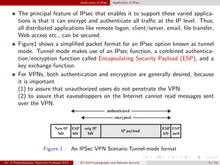
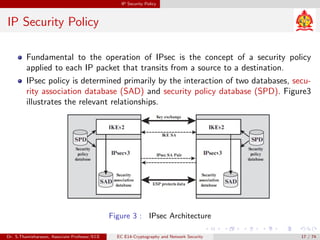
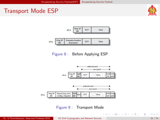
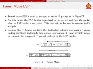
SlideShare a Scribd company logo
Cryptography and Network Security
Dr. S.Thamizharasan
Associate Professor
Department of ECE
Sri Manakula Vinayagar Engineering College
thamizharasansece@smvec.ac.in
Dr. S.Thamizharasan, Associate Professor/ECE EC E14-Cryptography and Network Security 1 / 74
Overview I
1 IP Security Overview
2 Application of IPsec
3 Benefits of IPsec
4 Routing Applications
5 IPsec Documents
6 IPsec Services
7 IP Security Policy
Dr. S.Thamizharasan, Associate Professor/ECE EC E14-Cryptography and Network Security 2 / 74
Overview II
8 Encapsulating Security Payload(ESP)
9 Web Security Considerations
10 Transport Layer Security
11 Internet Mail Architecture
Dr. S.Thamizharasan, Associate Professor/ECE EC E14-Cryptography and Network Security 3 / 74
Unit IV
Network Security
Dr. S.Thamizharasan, Associate Professor/ECE EC E14-Cryptography and Network Security 4 / 74
UNIT-IV
Dr. S.Thamizharasan, Associate Professor/ECE EC E14-Cryptography and Network Security 5 / 74
IP Security Overview
In 1994, the Internet Architecture Board (IAB): issued a report titled Security
in the Internet Architecture.
The report identified key areas for security mechanisms. Among these were the
need to secure the network infrastructure from unauthorized monitoring and
control of network traffic and the need to secure end-user to end-user traffic
using authentication and encryption mechanisms.
To provide security, the IAB included authentication and encryption as neces-
sary security features in the next generation IP, which has been issued as IPv4
and IPv6.
Dr. S.Thamizharasan, Associate Professor/ECE EC E14-Cryptography and Network Security 6 / 74
Application of IPsec
IPsec provides the capability to secure communications across a LAN, across
private and public WANs, and across the Internet. Examples of its use include:
Secure branch office connectivity over the Internet:
A company can build a secure virtual private network over the Internet or over
a public WAN. This enables a business to rely heavily on the Internet and
reduce its need for private networks, saving costs and network management
overhead.
Secure remote access over the Internet:
An end user whose system is equipped with IP security protocols can make
a local call to an Internet Service Provider (ISP) and gain secure access to a
company network. This reduces the cost of toll charges for traveling employees
and telecommuters.
Dr. S.Thamizharasan, Associate Professor/ECE EC E14-Cryptography and Network Security 7 / 74
Application of IPsec Application of IPsec
Application of IPsec
Establishing extranet and intranet connectivity with partners:
IPsec can be used to secure communication with other organizations, ensuring
authentication and confidentiality and providing a key exchange mechanism.
Enhancing electronic commerce security:
Even though some Web and electronic commerce applications have built-in
security protocols, the use of IPsec enhances that security. IPsec guarantees
that all traffic designated by the network administrator is both encrypted and
authenticated, adding an additional layer of security to whatever is provided
at the application layer.
Dr. S.Thamizharasan, Associate Professor/ECE EC E14-Cryptography and Network Security 8 / 74
Application of IPsec Application of IPsec
The principal feature of IPsec that enables it to support these varied applica-
tions is that it can encrypt and authenticate all traffic at the IP level. Thus,
all distributed applications like remote logon, client/server, email, file transfer,
Web access etc., can be secured.
Figure1 shows a simplified packet format for an IPsec option known as tunnel
mode. Tunnel mode makes use of an IPsec function, a combined authentica-
tion/encryption function called Encapsulating Security Payload (ESP), and a
key exchange function.
For VPNs, both authentication and encryption are generally desired, because
it is important
(1) to assure that unauthorized users do not penetrate the VPN
(2) to assure that eavesdroppers on the Internet cannot read messages sent
over the VPN.
Figure 1 : An IPSec VPN Scenario:Tunnel-mode format
Dr. S.Thamizharasan, Associate Professor/ECE EC E14-Cryptography and Network Security 9 / 74
Application of IPsec Application of IPsec
Application of IPsec
Figure2 is a typical scenario of IPsec usage. An organization maintains LANs
at dispersed locations. Nonsecure IP traffic is conducted on each LAN.
Fortraffic offsite, through some sort of private or public WAN, IPsec protocols
are used. These protocols operate in networking devices, such as a router or
firewall, that connect each LAN to the outside world.
The IPsec networking device will typically encrypt all traffic going into the WAN
and decrypt traffic coming from the WAN; these operations are transparent to
workstations and servers on the LAN.
Secure transmission is also possible with individual users who dial into the
WAN. Such user workstations must implement the IPsec protocols to provide
security.
Dr. S.Thamizharasan, Associate Professor/ECE EC E14-Cryptography and Network Security 10 / 74
Application of IPsec Application of IPsec
Application of IPsec
Figure 2 : An IPSec VPN Scenario:Example coniguration
Dr. S.Thamizharasan, Associate Professor/ECE EC E14-Cryptography and Network Security 11 / 74
Benefits of IPsec
Benefits of IPsec
When IPsec is implemented in a firewall or router, it provides strong security
that can be applied to all traffic crossing the perimeter. Traffic within a com-
pany or workgroup does not incur the overhead of security-related processing.
IPsec in a firewall is resistant to bypass if all traffic from the outside must use
IP and the firewall is the only means of entrance from the Internet into the
organization.
IPsec is below the transport layer (TCP, UDP) and so is transparent to appli-
cations. There is no need to change software on a user or server system when
IPsec is implemented in the firewall or router. Even if IPsec is implemented in
end systems, upper-layer software, including applications, is not affected.
IPsec can be transparent to end users. There is no need to train users on secu-
rity mechanisms, issue keying material on a per-user basis, or revoke keying
material when users leave the organization.
IPsec can provide security for individual users if needed. This is useful for off-
site workers and for setting up a secure virtual subnetwork within an organiza-
tion for sensitive applications.
Dr. S.Thamizharasan, Associate Professor/ECE EC E14-Cryptography and Network Security 12 / 74
Routing Applications
In addition to supporting end users and protecting premises systems and networks,
IPsec can play a vital role in the routing architecture required for internetworking.
IPsec can assure that
A router advertisement (a new router advertises its presence) comes from an
authorized router.
A neighbor advertisement (a router seeks to establish or maintain a neighbor
relationship with a router in another routing domain) comes from an authorized
router.
A redirect message comes from the router to which the initial IP packet was
sent.
A routing update is not forged.
Without such security measures, an opponent can disrupt communications
or divert some traffic. Routing protocols such as Open Shortest Path First
(OSPF) should be run on top of security associations between routers that are
defined by IPsec.
Dr. S.Thamizharasan, Associate Professor/ECE EC E14-Cryptography and Network Security 13 / 74
IPsec Documents
IPsec Documents
IPsec encompasses three functional areas:
(i) authentication
(ii) confidentiality
(iii) key management
The documents can be categorized into the following groups:
Architecture:Covers the general concepts, security requirements, definitions,
and mechanisms defining IPsec technology. The current specification is RFC
4301, Security Architecture for the Internet Protocol.
Authentication Header (AH):AH is an extension header to provide mes- sage
authentication. The current specification is RFC 4302, IP Authentication
Header. Because message authentication is provided by ESP, the use of AH
is deprecated. It is included in IPsecv3 for backward compatibility but should
not be used in new applications.
Dr. S.Thamizharasan, Associate Professor/ECE EC E14-Cryptography and Network Security 14 / 74
IPsec Documents IPsec Documents
IPsec Documents
Encapsulating Security Payload (ESP):ESP consists of an encapsulat- ing header
and trailer used to provide encryption or combined encryption/ authentication.
The current specification is RFC 4303, IP Encapsulating Security Payload (ESP).
Internet Key Exchange (IKE):This is a collection of documents describing the key
management schemes for use with IPsec. The main specification is RFC 7296,
Internet Key Exchange (IKEv2) Protocol, but there are a number of related RFCs.
Cryptographic algorithms:This category encompasses a large set of docu- ments
that define and describe cryptographic algorithms for encryption, message
authentication, pseudorandom functions (PRFs), and cryptographic key exchange.
There are a variety of other IPsec-related RFCs, including those dealing with
security policy and management information base (MIB) content.
Dr. S.Thamizharasan, Associate Professor/ECE EC E14-Cryptography and Network Security 15 / 74
IPsec Services
IPsec Services
IPsec provides security services at the IP layer by enabling a system to select
required security protocols, determine the algorithm(s) to use for the service(s),
and put in place any cryptographic keys required to provide the requested
services.
Two protocols are used to provide security: an authentication protocol des-
ignated by the header of the protocol, Authentication Header (AH); and a
combined encryption/authentication protocol designated by the format of the
packet for that protocol, Encapsulating Security Payload (ESP).
RFC 4301 lists the following services:
(i) Access control
(ii) Connectionless integrity
(iii) Data origin authentication
(iv) Rejection of replayed packets
(v) Confidentiality (encryption)
(vi) Limited traffic flow confidentiality
Dr. S.Thamizharasan, Associate Professor/ECE EC E14-Cryptography and Network Security 16 / 74
IP Security Policy
IP Security Policy
Fundamental to the operation of IPsec is the concept of a security policy
applied to each IP packet that transits from a source to a destination.
IPsec policy is determined primarily by the interaction of two databases, secu-
rity association database (SAD) and security policy database (SPD). Figure3
illustrates the relevant relationships.
Figure 3 : IPsec Architecture
Dr. S.Thamizharasan, Associate Professor/ECE EC E14-Cryptography and Network Security 17 / 74
IP Security Policy Security Associations
A key concept that appears in both the authentication and confidentiality
mechanisms for IP is the security association (SA).
An association is a one-way logical connection between a sender and a receiver
that affords security services to the traffic carried on it.
If a peer relationship is needed for two-way secure exchange, then two security
associations are required.
A security association is uniquely identified by three parameters.
Security Parameters Index (SPI): A 32-bit unsigned integer assigned to this SA
and having local significance only. The SPI is carried in AH and ESP headers
to enable the receiving system to select the SA under which a received packet
will be processed.
IP Destination Address:This is the address of the destination endpoint of the
SA, which may be an end-user system or a network system such as a firewall
or router.
Security Protocol Identifier:This field from the outer IP header indicates whether
the association is an AH or ESP security association.
Hence, in any IP packet, the security association is uniquely identified by the
Destination Address in the IPv4 or IPv6 header and the SPI in the enclosed
extension header (AH or ESP).
Dr. S.Thamizharasan, Associate Professor/ECE EC E14-Cryptography and Network Security 18 / 74
IP Security Policy Security Association Database
Security Association Database
In each IPsec implementation, there is a nominal Security Association Database
that defines the parameters associated with each SA. A security association is
normally defined by the following parameters in an SAD entry.
Security Parameter Index: A 32-bit value selected by the receiving end of an
SA to uniquely identify the SA. In an SAD entry for an outbound SA, the SPI
is used to construct the packets AH or ESP header. In an SAD entry for an
inbound SA, the Security Parameters Index (SPI) is used to map traffic to the
appropriate SA.
Sequence Number Counter: A 32-bit value used to generate the Sequence
Number field in AH or ESP headers, described in Section 20.3 (required for all
implementations).
Sequence Counter Overflow: A flag indicating whether overflow of the Se-
quence Number Counter should generate an auditable event and prevent fur-
ther transmission of packets on this SA (required for all implementations).
Anti-Replay Window: Used to determine whether an inbound AH or ESP
packet is a replay, described in Section 20.3 (required for all implementations).
Dr. S.Thamizharasan, Associate Professor/ECE EC E14-Cryptography and Network Security 19 / 74
IP Security Policy Security Association Database
Security Association Database
AH Information: Authentication algorithm, keys, key lifetimes, and related
parameters being used with AH (required for AH implementations).
ESP Information: Encryption and authentication algorithm, keys, initialization
values, key lifetimes, and related parameters being used with ESP (required
for ESP implementations).
Lifetime of this Security Association: A time interval or byte count after which
an SA must be replaced with a new SA (and new SPI) or terminated, plus an
indication of which of these actions should occur (required for all implementa-
tions). IPsec Protocol Mode:Tunnel, transport, or wildcard.
Path MTU: Any observed path maximum transmission unit (maximum size of
a packet that can be transmitted without fragmentation) and aging variables
(required for all implementations).
The key management mechanism that is used to distribute keys is coupled
to the authentication and privacy mechanisms only by way of the Security
Parameters Index (SPI). Hence, authentication and privacy have been specified
independent of any specific key management mechanism.
Dr. S.Thamizharasan, Associate Professor/ECE EC E14-Cryptography and Network Security 20 / 74
IP Security Policy Security Policy Database
Security Policy Database
Security Policy Database(SPD) contains entries, each of which defines a subset
of IP traffic and points to an SA for that traffic. In more complex environments,
there may be multiple entries that potentially relate to a single SA or multiple
SAs associated with a single SPD entry.
Each SPD entry is defined by a set of IP and upper-layer protocol field values,
called selectors. In effect, these selectors are used to filter outgoing traffic in
order to map it into a particular SA.
Outbound processing obeys the following general sequence for each IP packet.
(i) Compare the values of the appropriate fields in the packet (the selector
fields) against the SPD to find a matching SPD entry, which will point to zero
or more SAs.
(ii) Determine the SA if any for this packet and its associated SPI
(iii) Do the required IPsec processing (i.e., AH or ESP processing).
Dr. S.Thamizharasan, Associate Professor/ECE EC E14-Cryptography and Network Security 21 / 74
IP Security Policy Security Policy Database
The following selectors determine an SPD entry:
Remote IP Address: This may be a single IP address, an enumerated list or
range of addresses, or a wildcard (mask) address. The latter two are required
to support more than one destination system sharing the same SA (e.g., behind
a firewall).
Local IP Address: This may be a single IP address, an enumerated list or
range of addresses, or a wildcard (mask) address. The latter two are required
to support more than one source system sharing the same SA (e.g., behind a
firewall).
Next Layer Protocol: The IP protocol header (IPv4, IPv6, or IPv6 Extension)
includes a field (Protocol for IPv4, Next Header for IPv6 or IPv6 Extension)
that designates the protocol operating over IP. If AH or ESP is used, then this
IP protocol header immediately precedes the AH or ESP header in the packet.
Name: A user identifier from the operating system. This is not a field in the IP
or upper layer headers but is available if IPsec is running on the same operating
system as the user.
Local and Remote Ports: These may be individual TCP or UDP port values,
an enumerated list of ports, or a wildcard port.
Dr. S.Thamizharasan, Associate Professor/ECE EC E14-Cryptography and Network Security 22 / 74
Encapsulating Security Payload(ESP)
ESP can be used to provide confidentiality, data origin authentication, connec-
tionless integrity, an anti-replay service and traffic flow confidentiality.
The set of services provided depends on options selected at the time of Security
Association (SA) establishment and on the locationof the implementation in a
network topology.
ESP can work with a variety of encryption and authentication algorithms,
including authenticated encryption algorithms such as GCM.
Dr. S.Thamizharasan, Associate Professor/ECE EC E14-Cryptography and Network Security 23 / 74
Encapsulating Security Payload(ESP) Encapsulating Security Payload
Encapsulating Security Payload
Figure4 shows the top-level format of an ESP packet. It contains the following
fields:
Security Parameters Index (32 bits):Identifies a security association.
Sequence Number (32 bits): A monotonically increasing counter value; this
provides an anti-replay function, as discussed for AH
Payload Data (variable): This is a transport-level segment (transport mode)
or IP packet (tunnel mode) that is protected by encryption.
Figure 4 : ESP Packet Format:Top-level format of an ESP Packet
Dr. S.Thamizharasan, Associate Professor/ECE EC E14-Cryptography and Network Security 24 / 74
Encapsulating Security Payload(ESP) Encapsulating Security Payload
Encapsulating Security Payload
Padding (0255 bytes): Padding field is used to expand the plaintext (consisting
of the Payload Data, Padding, Pad Length, and Next Header fields) to the
required length.
Pad Length (8 bits): Indicates the number of pad bytes immediately preceding
this field.
Dr. S.Thamizharasan, Associate Professor/ECE EC E14-Cryptography and Network Security 25 / 74
Encapsulating Security Payload(ESP) Encapsulating Security Payload
Encapsulating Security Payload
Next Header (8 bits): Identifies the type of data contained in the payload
data field by identifying the first header in that payload (e.g., an extension
header in IPv6, or an upper-layer protocol such as TCP).
Integrity Check Value (variable): A variable-length field (must be an integral
number of 32-bit words) that contains the Integrity Check Value computed
over the ESP packet minus the Authentication Data field.
Dr. S.Thamizharasan, Associate Professor/ECE EC E14-Cryptography and Network Security 26 / 74
Encapsulating Security Payload(ESP) Encapsulating Security Payload
Encapsulating Security Payload
Figure5 shows the substructure of payload data
Two additional fields may be present in the payload as in Figure5. An initial-
ization value (IV), or nonce, is present if this is required by the encryption or
authenticated encryption algorithm used for ESP.
If tunnel mode is being used, then the IPsec implementation may add traf-
fic flow confidentiality (TFC) padding after the Payload Data and before the
Padding field.
Figure 5 : ESP Packet Format:Substructure of payload data
Dr. S.Thamizharasan, Associate Professor/ECE EC E14-Cryptography and Network Security 27 / 74
Encapsulating Security Payload(ESP) Encapsulating Security Payload
Transport and Tunnel Modes
Figure6,7 shows two ways in which the IPsec ESP service can be used.
In transport mode, encryption (and optionally authentication) is provided di-
rectly between two hosts.
Figure7 shows how tunnel mode operation can be used to set up a virtual
private network.
Figure 6 : Transport-level security
Dr. S.Thamizharasan, Associate Professor/ECE EC E14-Cryptography and Network Security 28 / 74
Encapsulating Security Payload(ESP) Encapsulating Security Payload
Transport and Tunnel Modes
In tunnel mode, an organization has four private networks interconnected across
the Internet.
Hosts on the internal networks use the Internet for transport of data but do
not interact with other Internet-based hosts.
By terminating the tunnels at the security gateway to each internal network,
the configuration allows the hosts to avoid implementing the security capability.
Figure 7 : A virtual private network via tunnel mode
Dr. S.Thamizharasan, Associate Professor/ECE EC E14-Cryptography and Network Security 29 / 74
Encapsulating Security Payload(ESP) Encapsulating Security Payload
Transport Mode ESP
Packet format of IPv4 and IPv6 is shown in Figure8.
Transport mode ESP is used to encrypt and optionally authenticate the data
carried by IP (e.g., a TCP segment), as shown in Figure9.
For this mode using IPv4, the ESP header is inserted into the IP packet im-
mediately prior to the transport-layer header (e.g., TCP, UDP, ICMP), and an
ESP trailer (Padding, Pad Length, and Next Header fields) is placed after the
IP packet.
If authentication is selected, the ESP Authentication Data field is added after
the ESP trailer. The entire transport-level segment plus the ESP trailer are
encrypted. Authentication covers all of the ciphertext plus the ESP header.
Dr. S.Thamizharasan, Associate Professor/ECE EC E14-Cryptography and Network Security 30 / 74
Encapsulating Security Payload(ESP) Encapsulating Security Payload
Transport Mode ESP
Figure 8 : Before Applying ESP
Figure 9 : Transport Mode
Dr. S.Thamizharasan, Associate Professor/ECE EC E14-Cryptography and Network Security 31 / 74
Encapsulating Security Payload(ESP) Encapsulating Security Payload
Transport Mode ESP
Transport mode operation may be summarized as follows:
(i) At the source, the block of data consisting of the ESP trailer plus the entire
transport-layer segment is encrypted and the plaintext of this block is replaced
with its ciphertext to form the IP packet for transmission. Authentication is
added if this option is selected.
(ii) The packet is then routed to the destination. Each intermediate router
needs to examine and process the IP header plus any plaintext IP extension
headers but does not need to examine the ciphertext.
(iii) The destination node examines and processes the IP header plus any
plaintext IP extension headers. Then, on the basis of the SPI in the ESP
header, the destination node decrypts the remainder of the packet to recover
the plaintext transport-layer segment.
Transport mode operation provides confidentiality for any application that uses
it, thus avoiding the need to implement confidentiality in every individual ap-
plication.
One drawback to this mode is that it is possible to do traffic analysis on the
transmitted packets.
Dr. S.Thamizharasan, Associate Professor/ECE EC E14-Cryptography and Network Security 32 / 74
Encapsulating Security Payload(ESP) Encapsulating Security Payload
Tunnel Mode ESP
Tunnel mode ESP is used to encrypt an entire IP packet as in Figure??.
For this mode, the ESP header is prefixed to the packet and then the packet
plus the ESP trailer is encrypted. This method can be used to counter traffic
analysis.
Because the IP header contains the destination address and possibly source
routing directives and hop-by-hop option information, it is not possible simply
to transmit the encrypted IP packet prefixed by the ESP header.
Figure 10 : Tunnel Mode
Dr. S.Thamizharasan, Associate Professor/ECE EC E14-Cryptography and Network Security 33 / 74
Encapsulating Security Payload(ESP) Encapsulating Security Payload
Tunnel Mode ESP
Intermediate routers would be unable to process such a packet. Therefore,
it is necessary to encapsulate the entire block (ESP header plus ciphertext
plus Authentication Data, if present) with a new IP header that will contain
sufficient information for routing but not for traffic analysis.
Whereas the transport mode is suitable for protecting connections between
hosts that support the ESP feature, the tunnel mode is useful in a configuration
that includes a firewall or other sort of security gateway that protects a trusted
network from external networks.
In this case, encryption occurs only between an external host and the security
gateway or between two security gateways. This relieves hosts on the internal
network of the processing burden of encryption and simplifies the key distri-
bution task by reducing the number of needed keys. Further, it thwarts traffic
analysis based on ultimate destination.
Dr. S.Thamizharasan, Associate Professor/ECE EC E14-Cryptography and Network Security 34 / 74
Encapsulating Security Payload(ESP) Encapsulating Security Payload
Protocol Architecture for ESP
Consider a case in which an external host wishes to communicate with a host on
an internal network protected by a firewall, and in which ESP is implemented
in the external host and the firewalls.
The following steps occur for transfer of a transport-layer segment from the
external host to the internal host.
(i) The source prepares an inner IP packet with a destination address of the
target internal host. This packet is prefixed by an ESP header; then the packet
and ESP trailer are encrypted and Authentication Data may be added. The
resulting block is encapsulated with a new IP header (base header plus optional
extensions such as routing and hop-by-hop options for IPv6) whose destination
address is the firewall; this forms the outer IP packet.
Dr. S.Thamizharasan, Associate Professor/ECE EC E14-Cryptography and Network Security 35 / 74
Encapsulating Security Payload(ESP) Encapsulating Security Payload
Protocol Architecture for ESP
(ii) The outer packet is routed to the destination firewall. Each intermediate
router needs to examine and process the outer IP header plus any outer IP
extension headers but does not need to examine the ciphertext.
(iii) The destination firewall examines and processes the outer IP header plus
any outer IP extension headers. Then, on the basis of the SPI in the ESP
header, the destination node decrypts the remainder of the packet to recover
the plaintext inner IP packet. This packet is then transmitted in the internal
network.
(iv) The inner packet is routed through zero or more routers in the internal
network to the destination host.
Figure11,12 shows the protocol architecture for the two modes.
Dr. S.Thamizharasan, Associate Professor/ECE EC E14-Cryptography and Network Security 36 / 74
Encapsulating Security Payload(ESP) Encapsulating Security Payload
Figure 11 : Protocol Operation for ESP: Transport mode
Figure 12 : Protocol Operation for ESP: Tunnel mode
Dr. S.Thamizharasan, Associate Professor/ECE EC E14-Cryptography and Network Security 37 / 74
Web Security Considerations
The World Wide Web is fundamentally a client/server application running over
the Internet and TCP/IP intranets.
Web Security Threats:
Passive attacks include eavesdropping on network traffic between browser and
server and gaining access to information on a Web site that is supposed to be
restricted. Active attacks include impersonating another user, altering mes-
sages in transit between client and server, and altering information on a Web
site.
Another way to classify Web security threats is in terms of the location of the
threat: Web server, Web browser, and network traffic between browser and
server.
Web Traffic Security Approaches: A number of approaches to providing Web
security are possible. The various approaches that have been considered are
similar in the services they provide and, to some extent, in the mechanisms
that they use, but they differ with respect to their scope of applicability and
their relative location within the TCP/IP protocol stack.
Dr. S.Thamizharasan, Associate Professor/ECE EC E14-Cryptography and Network Security 38 / 74
Web Security Considerations
Figure 13 : A Comparison of Threats on the Web.
Dr. S.Thamizharasan, Associate Professor/ECE EC E14-Cryptography and Network Security 39 / 74
Web Security Considerations Web Security Considerations
Web Security Considerations
The World Wide Web is fundamentally a client/server application running over
the Internet and TCP/IP intranets.
Web Security Threats:
Passive attacks include eavesdropping on network traffic between browser and
server and gaining access to information on a Web site that is supposed to be
restricted. Active attacks include impersonating another user, altering mes-
sages in transit between client and server, and altering information on a Web
site.
Another way to classify Web security threats is in terms of the location of the
threat: Web server, Web browser, and network traffic between browser and
server.
Web Traffic Security Approaches: A number of approaches to providing Web
security are possible. The various approaches that have been considered are
similar in the services they provide and, to some extent, in the mechanisms
that they use, but they differ with respect to their scope of applicability and
their relative location within the TCP/IP protocol stack.
Dr. S.Thamizharasan, Associate Professor/ECE EC E14-Cryptography and Network Security 40 / 74
Web Security Considerations Web Security Considerations
Web Security Considerations
One way to provide Web security is to use IP security (IPsec) as in Figure14(a).
The advantage of using IPsec is that it is transparent to end users and appli-
cations and provides a general-purpose solution. Furthermore, IPsec includes
a filtering capability so that only selected traffic need incur the overhead of
IPsec processing.
Figure 14 : Relative Location of Security Facilities in the TCP/IP Protocol Stack.
Dr. S.Thamizharasan, Associate Professor/ECE EC E14-Cryptography and Network Security 41 / 74
Web Security Considerations Web Security Considerations
Web Security Considerations
Another relatively general-purpose solution is to implement security just above
TCP as in Figure14(b).
The foremost example of this approach is the Secure Sockets Layer (SSL) and
the follow-on Internet standard known as Transport Layer Security (TLS).
At this level, there are two implementation choices.
For full generality, SSL (or TLS) could be provided as part of the underlying
protocol suite and therefore be transparent to applications.
Alternatively, TLS can be embedded in specific packages. For example, virtu-
ally all browsers come equipped with TLS, and most Web servers have imple-
mented the protocol.
Application-specific security services are embedded within the particular appli-
cation. Figure14(c). shows examples of this architecture. The advantage of
this approach is that the service can be tailored to the specific needs of a given
application.
Dr. S.Thamizharasan, Associate Professor/ECE EC E14-Cryptography and Network Security 42 / 74
Transport Layer Security
Transport Layer Security(TLS)
One of the most widely used security services is Transport Layer Security (TSL);
the current version is Version 1.2, defined in RFC 5246.
TLS is an Internet standard that evolved from a commercial protocol known
as Secure Sockets Layer(SSL).
Figure 15 : TLS Protocol Stack
Dr. S.Thamizharasan, Associate Professor/ECE EC E14-Cryptography and Network Security 43 / 74
Transport Layer Security Transport Layer Security
TLS Architecture
TLS is designed to make use of TCP to provide a reliable end-to-end secure
service. TLS is not a single protocol but rather two layers of protocols, as
illustrated in Figure15.
The TLS Record Protocol provides basic security services to various higher
layer protocols.
In particular, the Hypertext Transfer Protocol (HTTP), which provides the
transfer service for Web client/server interaction, can operate on top of TLS.
Three higher-layer protocols are defined as part of TLS:
(i) the Handshake Protocol
(ii) the Change Cipher Spec Protocol
(iii) the Alert Protocol.
These TLS specific protocols are used in the management of TLS exchanges.
A fourth protocol, the Heartbeat Protocol, is defined in a separate RFC.
Dr. S.Thamizharasan, Associate Professor/ECE EC E14-Cryptography and Network Security 44 / 74
Transport Layer Security Transport Layer Security
TLS Architecture
Two important TLS concepts are the TLS session and the TLS connection,
which are defined in the specification as follows:
(i) Connection: A connection is a transport that provides a suitable type of
service. For TLS, such connections are peer-to-peer relationships. The con-
nections are transient. Every connection is associated with one session.
(ii) Session: A TLS session is an association between a client and a server.
Sessions are created by the Handshake Protocol. Sessions define a set of
cryptographic security parameters, which can be shared among multiple con-
nections. Sessions are used to avoid the expensive negotiation of new security
parameters for each connection.
Dr. S.Thamizharasan, Associate Professor/ECE EC E14-Cryptography and Network Security 45 / 74
Transport Layer Security Transport Layer Security
TLS Architecture
A session state is defined by the following parameters:
Session identifier: An arbitrary byte sequence chosen by the server to identify
an active or resumable session state.
Peer certificate: An X509.v3 certificate of the peer. This element of the state
may be null.
Compression method: The algorithm used to compress data prior to encryption.
Cipher spec: Specifies the bulk data encryption algorithm (such as null, AES,
etc.) and a hash algorithm (such as MD5 or SHA-1) used for MAC calculation.
It also defines cryptographic attributes such as he hash size.
Master secret: 48-byte secret shared between the client and server.
Is resumable: A flag indicating whether the session can be used to initiate new
connections.
Dr. S.Thamizharasan, Associate Professor/ECE EC E14-Cryptography and Network Security 46 / 74
Transport Layer Security Transport Layer Security
A connection state is defined by the following parameters:
Server and client random: Byte sequences that are chosen by the server and
client for each connection.
Server write MAC secret: The secret key used in MAC operations on data sent
by the server.
Client write MAC secret: The symmetric key used in MAC operations on data
sent by the client.
Server write key: The symmetric encryption key for data encrypted by the
server and decrypted by the client.
Client write key: The symmetric encryption key for data encrypted by the client
and decrypted by the server.
Initialization vectors: When a block cipher in CBC mode is used, an initial-
ization vector (IV) is maintained for each key. This field is first initialized by
the TLS Handshake Protocol. Thereafter, the final ciphertext block from each
record is preserved for use as the IV with the following record.
Sequence numbers: Each party maintains separate sequence numbers for trans-
mitted and received messages for each connection. When a party sends or
receives a change cipher spec message, the appropriate sequence number is set
to zero. Sequence numbers may not exceed 264
− 1.
Dr. S.Thamizharasan, Associate Professor/ECE EC E14-Cryptography and Network Security 47 / 74
Transport Layer Security Transport Layer Security
TLS Record Protocol
The TLS Record Protocol provides two services for TLS connections:
(i) Confidentiality: The Handshake Protocol defines a shared secret key that
is used for conventional encryption of TLS payloads.
(ii) Message Integrity: The Handshake Protocol also defines a shared secret
key that is used to form a message authentication code (MAC).
Figure16 indicates the overall operation of the TLS Record Protocol.
The Record Protocol takes an application message to be transmitted, frag-
ments the data into manageable blocks, optionally compresses the data, ap-
plies a MAC, encrypts, adds a header, and transmits the resulting unit in a
TCP segment.
Received data are decrypted, verified, decompressed, and reassembled before
being delivered to higher-level users.
Dr. S.Thamizharasan, Associate Professor/ECE EC E14-Cryptography and Network Security 48 / 74
Transport Layer Security Transport Layer Security
Figure 16 : TLS Protocol Stack
Dr. S.Thamizharasan, Associate Professor/ECE EC E14-Cryptography and Network Security 49 / 74
Transport Layer Security Transport Layer Security
The final step of TLS Record Protocol processing is to prepend a header con-
sisting of the following fields:
(i) Content Type (8 bits): The higher-layer protocol used to process the en-
closed fragment.
(ii) Major Version (8 bits): Indicates major version of TLS in use. For TLSv2,
the value is 3.
(iii) Minor Version (8 bits): Indicates minor version in use. For TLSv2, the
value is 1.
(iv) Compressed Length (16 bits): The length in bytes of the plaintext fragment
(or compressed fragment if compression is used). The maximum value is 214
+
2048.
Figure 17 : TLS Record Format.
Dr. S.Thamizharasan, Associate Professor/ECE EC E14-Cryptography and Network Security 50 / 74
Transport Layer Security Transport Layer Security
Change Cipher Spec Protocol
The Change Cipher Spec Protocol is one of the four TLS-specific protocols
that use the TLS Record Protocol, and it is the simplest.
This protocol consists of a single message as in Figure18(a), which consists of
a single byte with the value 1. The sole purpose of this message is to cause
the pending state to be copied into the current state, which updates the cipher
suite to be used on this connection.
Figure 18 : TLS Record Protocol Payload.
Dr. S.Thamizharasan, Associate Professor/ECE EC E14-Cryptography and Network Security 51 / 74
Transport Layer Security Transport Layer Security
Alert Protocol
The Alert Protocol is used to convey TLS-related alerts to the peer entity.
As with other applications that use TLS, alert messages are compressed and
encrypted, as specified by the current state.
Each message in this protocol consists of two bytes as in Figure18(b). The
first byte takes the value warning (1) or fatal (2) to convey the severity of the
message.
If the level is fatal, TLS immediately terminates the connection. Other con-
nections on the same session may continue, but no new connections on this
session may be established.
The second byte contains a code that indicates the specific alert.
The following alerts are always fatal:
(i) unexpected message: An inappropriate message was received.
(ii) bad record mac: An incorrect MAC was received.
(iii) decompression failure: The decompression function received improper in-
put (e.g., unable to decompress or decompress to greater than maximum al-
lowable length).
Dr. S.Thamizharasan, Associate Professor/ECE EC E14-Cryptography and Network Security 52 / 74
Transport Layer Security Transport Layer Security
Alert Protocol
(iv) handshake failure: Sender was unable to negotiate an acceptable set of
security parameters given the options available.
(v) illegal parameter: A field in a handshake message was out of range or
inconsistent with other fields
(vi) decryption failed: A ciphertext decrypted in an invalid way; either it was
not an even multiple of the block length or its padding values, when checked,
were incorrect.
(vii) record overflow: A TLS record was received with a payload (ciphertext)
whose length exceeds 214
+2048 bytes, or the ciphertext decrypted to a length
of greater than 214
+ 2048 bytes.
(viii) unknown ca: A valid certificate chain or partial chain was received, but
the certificate was not accepted because the CA certificate could not be located
or could not be matched with a known, trusted CA.
Dr. S.Thamizharasan, Associate Professor/ECE EC E14-Cryptography and Network Security 53 / 74
Transport Layer Security Transport Layer Security
Alert Protocol
(ix) access denied: A valid certificate was received, but when access control
was applied, the sender decided not to proceed with the negotiation.
(x) decode error: A message could not be decoded, because either a field was
out of its specified range or the length of the message was incorrect.
(xi) export restriction: A negotiation not in compliance with export restrictions
on key length was detected.
(xii) protocol version: The protocol version the client attempted to negotiate
is recognized but not supported.
(xiii) insufficient security: Returned instead of handshake failure when a nego-
tiation has failed specifically because the server requires ciphers more secure
than those supported by the client.
(xiv) internal error: An internal error unrelated to the peer or the correctness
of the protocol makes it impossible to continue.
Dr. S.Thamizharasan, Associate Professor/ECE EC E14-Cryptography and Network Security 54 / 74
Transport Layer Security Transport Layer Security
Handshake Protocol
The most complex part of TLS is the Handshake Protocol. This protocol allows
the server and client to authenticate each other and to negotiate an encryption
and MAC algorithm and cryptographic keys to be used to protect data sent in
a TLS record.
The Handshake Protocol is used before any application data is transmitted.
The Handshake Protocol consists of a series of messages exchanged by client
and server. The format of Handshake protocol is shown in Figure19(c).
Figure 19 : TLS Record Protocol Payload.
Dr. S.Thamizharasan, Associate Professor/ECE EC E14-Cryptography and Network Security 55 / 74
Transport Layer Security Transport Layer Security
Handshake Protocol
Each message has three fields:
(i) Type (1 byte): Indicates one of 10 messages. Figure20 lists the defined
message types.
(ii) Length (3 bytes): The length of the message in bytes.
(iii) Content (≥ 0 bytes): The parameters associated with this message; these
are listed in Figure20.
Figure 20 : TLS Handshake Protocol Message Types.
Dr. S.Thamizharasan, Associate Professor/ECE EC E14-Cryptography and Network Security 56 / 74
Transport Layer Security Transport Layer Security
Figure 21 : Handshake Protocol Action
Dr. S.Thamizharasan, Associate Professor/ECE EC E14-Cryptography and Network Security 57 / 74
Transport Layer Security Transport Layer Security
Handshake Protocol
Figure21 shows the initial exchange needed to establish a logical connection
between client and server. The exchange can be viewed as having four phases:
Phase1 Establish Security Capabilities: Phase 1 initiates a logical connection
and establishes the security capabilities that will be associated with it.
The exchange is initiated by the client, which sends a client hello message.
Phase2 Server Authentication and Key Exchange: The server begins this phase
by sending its certificate if it needs to be authenticated.
The certificate message is required for any agreed-on key exchange method
except anonymous DiffieHellman.
If fixed DiffieHellman is used, this certificate message functions as the servers
key exchange message because it contains the servers public Diffie Hellman
parameters.
Next, a server key exchange message may be sent if it is required.
Dr. S.Thamizharasan, Associate Professor/ECE EC E14-Cryptography and Network Security 58 / 74
Transport Layer Security Transport Layer Security
Handshake Protocol
Phase3 Client Authentication and Key Exchange: Upon receipt of the server
done message, the client should verify that the server provided a valid certificate
(if required) and check that the server hello parameters are acceptable.
If all is satisfactory, the client sends one or more messages back to the server.
If the server has requested a certificate, the client begins this phase by sending
a certificate message.
If no suitable certificate is available, the client sends a no certificate alert
instead. Next is the client key exchange message, which must be sent in this
phase.
Dr. S.Thamizharasan, Associate Professor/ECE EC E14-Cryptography and Network Security 59 / 74
Transport Layer Security Transport Layer Security
Electronic Mail Security
Dr. S.Thamizharasan, Associate Professor/ECE EC E14-Cryptography and Network Security 60 / 74
Internet Mail Architecture
Email Components
Internet mail architecture consists of a user world in the form of Message User
Agents (MUA), and the transfer world, in the form of the Message Handling
Service (MHS), which is composed of Message Transfer Agents (MTA).
The MHS accepts a message from one user and delivers it to one or more
other users, creating a virtual MUA to MUA exchange environment. This
architecture involves three types of interoperability.
One is directly between users: messages must be formatted by the MUA on
behalf of the message author so that the message can be displayed to the
message recipient by the destination MUA.
There are also interoperability requirements between the MUA and the MHS.
first when a message is posted from an MUA to the MHS and later when it is
delivered from the MHS to the destination MUA. Interoperability is required
among the MTA components along the transfer path through the MHS.
Dr. S.Thamizharasan, Associate Professor/ECE EC E14-Cryptography and Network Security 61 / 74
Internet Mail Architecture
Figure 22 : Internet Mail Architecture.
Dr. S.Thamizharasan, Associate Professor/ECE EC E14-Cryptography and Network Security 62 / 74
Internet Mail Architecture Internet Mail Architecture
Email Components
Figure22 illustrates the key components of the Internet mail architecture, which
include the following:
Message User Agent (MUA): Operates on behalf of user actors and user ap-
plications. It is their representative within the email service. Typically, this
function is housed in the users computer and is referred to as a client emai
program or a local network email server. The author MUA formats a message
and performs initial submission into the MHS via a MSA. The recipient MUA
processes received mail for storage and/or display to the recipient user.
Mail Submission Agent (MSA): Accepts the message submitted by an MUA and
enforces the policies of the hosting domain and the requirements of Internet
standards. This function may be located together with the MUA or as a
separate functional model. In the latter case, the Simple Mail Transfer Protocol
(SMTP) is used between the MUA and the MSA.
Dr. S.Thamizharasan, Associate Professor/ECE EC E14-Cryptography and Network Security 63 / 74
Internet Mail Architecture Internet Mail Architecture
Email Components
Message Transfer Agent (MTA): Relays mail for one application-level hop. It is
like a packet switch or IP router in that its job is to make routing assessments
and to move the message closer to the recipients. Relaying is performed by
a sequence of MTAs until the message reaches a destination MDA. An MTA
also adds trace information to the message header. SMTP is used between
MTAs and between an MTA and an MSA or MDA.
Mail Delivery Agent (MDA): Responsible for transferring the message from the
MHS to the MS.
Message Store (MS): An MUA can employ a long-term MS. An MS can be
located on a remote server or on the same machine as the MUA. Typically an
MUA retrieves messages from a remote server using POP (Post OfficeProtocol)
or IMAP (Internet Message Access Protocol).
Dr. S.Thamizharasan, Associate Professor/ECE EC E14-Cryptography and Network Security 64 / 74
Internet Mail Architecture Internet Mail Architecture
Email Protocols
Two types of protocols are used for transferring email.
The first type is used to move messages through the Internet from source to
destination. The protocol used for this purpose is SMTP.
The second type consists of protocols used to transfer messages between mail
servers, of which IMAP and POP are the most commonly used.
Dr. S.Thamizharasan, Associate Professor/ECE EC E14-Cryptography and Network Security 65 / 74
Internet Mail Architecture Internet Mail Architecture
Simple Mail Transfer Protocol
SMTP encapsulates an email message in an envelope and is used to relay the
encapsulated messages from source to destination through multiple MTAs.
SMTP is a text-based client-server protocol where the client (email sender)
contacts the server (next-hop recipient) and issues a set of commands to tell
the server about the message to be sent, then sending the message itself. The
majority of these commands are ASCII text messages sent by the client and a
resulting return code (and additional ASCII text) returned by the server.
The transfer of a message from a source to its ultimate destination can occur
over a single SMTP client/server conversation over a single TCP connection.
Alternatively, an SMTP server may be an intermediate relay that assumes
the role of an SMTP client after receiving a message and then forwards that
message to an SMTP server along a route to the ultimate destination.
The operation of SMTP consists of a series of commands and response ex-
changed between the SMTP sender and receiver. The initiative is with the
SMTP sender, who establishes the TCP connection. Once the connection
is established the SMTP sender sends commands over the connection to the
receiver.
Dr. S.Thamizharasan, Associate Professor/ECE EC E14-Cryptography and Network Security 66 / 74
Internet Mail Architecture Internet Mail Architecture
Mail Access Protocol
Post Office Protocol (POP3) allows an email client (user agent) to download
an email from an email server (MTA).
POP3 user agents connect via TCP to the server. The user agent enters a
username and password (either stored internally for convenience or entered
each time by the user for stronger security).
After authorization, the UA can issue POP3 commands to retrieve and delete
mail.
As with POP3, Internet Mail Access Protocol (IMAP) also enables an email
client to access mail on an email server. IMAP is more complex than POP3.
IMAP provides stronger authentication than POP3 and provides other func-
tions not supported by POP3.
Dr. S.Thamizharasan, Associate Professor/ECE EC E14-Cryptography and Network Security 67 / 74
Internet Mail Architecture Internet Mail Architecture
Email Security Threats
Email security threats can be classified as follows:
Authenticity-related threats: Could result in unauthorized access to an enter-
prises email system.
Integrity-related threats: Could result in unauthorized modification of email
content.
Confidentiality-related threats: Could result in unauthorized disclosure of sen-
sitive information.
Availability-related threats: Could prevent end users from being able to send
or receive email.
Dr. S.Thamizharasan, Associate Professor/ECE EC E14-Cryptography and Network Security 68 / 74
Internet Mail Architecture Internet Mail Architecture
Secure/Multipurpose Internet Mail Extension (S/MIME)
Secure/Multipurpose Internet Mail Extension (S/MIME) is a security enhance-
mentto the MIME Internet email format standard based on technology from
RSA Data Security.
S/MIME is a complex capability that is defined in a number of documents.
The most important documents relevant to S/MIME include the following:
(i) RFC 5750, S/MIME Version 3.2 Certificate Handling: Specifies conventions
for X.509 certificate usage by (S/MIME) v3.2.
(ii) RFC 5751, S/MIME) Version 3.2 Message Specification: The principal
defining document for S/MIME message creation and processing.
(iii) RFC 4134, Examples of S/MIME Messages: Gives examples of message
bodies formatted using S/MIME.
(iv) RFC 2634, Enhanced Security Services for S/MIME: Describes four op-
tional security service extensions for S/MIME.
Dr. S.Thamizharasan, Associate Professor/ECE EC E14-Cryptography and Network Security 69 / 74
Internet Mail Architecture Internet Mail Architecture
Secure/Multipurpose Internet Mail Extension (S/MIME)
(v) RFC 5652, Cryptographic Message Syntax (CMS): Describes the Crypto-
graphic Message Syntax (CMS). This syntax is used to digitally sign, digest,
authenticate, or encrypt arbitrary message content.
(vi) RFC 3370, CMS Algorithms: Describes the conventions for using several
cryptographic algorithms with the CMS.
(vii) RFC 5752, Multiple Signatures in CMS: Describes the use of multiple,
parallel signatures for a message.
(viii) RFC 1847, Security Multiparts for MIME-Multipart/Signed and Multi-
part/Encrypted: Defines a framework within which security services may be
applied to MIME body parts. The use of a digital signature is relevant to
S/MIME, as explained subsequently.
Dr. S.Thamizharasan, Associate Professor/ECE EC E14-Cryptography and Network Security 70 / 74
Internet Mail Architecture Internet Mail Architecture
S/MIME
Figure 23 : Simplified S/MIME Functional Flow: Sender signs, then encrypts message
Dr. S.Thamizharasan, Associate Professor/ECE EC E14-Cryptography and Network Security 71 / 74
Internet Mail Architecture Internet Mail Architecture
S/MIME
Figure 24 : Simplified S/MIME Functional Flow: Receiver decrypts message, then
veriies senders signature
Dr. S.Thamizharasan, Associate Professor/ECE EC E14-Cryptography and Network Security 72 / 74
Internet Mail Architecture Internet Mail Architecture
Pretty Good Privacy(PGP)
An alternative email security protocol is Pretty Good Privacy (PGP), which
has essentially the same functionality as S/MIME.
There are two significant differences between S/MIME and OpenPGP:
(i) Key Certification: S/MIME uses X.509 certificates that are issued by Cer-
tificate Authorities. In OpenPGP, users generate their own OpenPGP public
and private keys and then solicit signatures for their public keys from individ-
uals or organizations to which they are known. Whereas X.509 certificates are
trusted if there is a valid PKIX chain to a trusted root, an OpenPGP public
key is trusted if it is signed by another OpenPGP public key that is trusted by
the recipient. This is called the Web-of-Trust.
Dr. S.Thamizharasan, Associate Professor/ECE EC E14-Cryptography and Network Security 73 / 74
Internet Mail Architecture Internet Mail Architecture
Pretty Good Privacy(PGP)
(ii) Key Distribution: OpenPGP does not include the senders public key with
each message, so it is necessary for recipients of OpenPGP messages to sepa-
rately obtain the senders public key in order to verify the message.
Many organizations post OpenPGP keys on TLS-protected websites: People
who wish to verify digital signatures or send these organizations encrypted
mail need to manually download these keys and add them to their OpenPGP
clients. Keys may also be registered with the OpenPGP public key servers,
which are servers that maintain a database of PGP public keys organized by
email address.
Anyone may post a public key to the OpenPGP key servers, and that public
key may contain any email address. There is no vetting of OpenPGP keys, so
users must use the Web-of-Trust to decide whether to trust a given public key.
Dr. S.Thamizharasan, Associate Professor/ECE EC E14-Cryptography and Network Security 74 / 74

More Related Content

What's hot

Ipsecurity
IpsecurityIpsecurity
8 Authentication Security Protocols
8 Authentication Security Protocols8 Authentication Security Protocols
8 Authentication Security Protocolsguestfbf635
 
Wireless Security
Wireless SecurityWireless Security
Overview of ip_security by JetArvind kumar Madhukar
Overview of ip_security by JetArvind kumar Madhukar Overview of ip_security by JetArvind kumar Madhukar
Overview of ip_security by JetArvind kumar Madhukar
ALLCAD Services Pvt Limited
 
Cn36539543
Cn36539543Cn36539543
Cn36539543
IJERA Editor
 
IPSec VPN & IPSec Protocols
IPSec VPN & IPSec ProtocolsIPSec VPN & IPSec Protocols
IPSec VPN & IPSec Protocols
NetProtocol Xpert
 
Firewall
FirewallFirewall
Firewall
nayakslideshare
 
IP Security
IP SecurityIP Security
IP Security
Dr.Florence Dayana
 
IPSec VPN tunnel
IPSec VPN tunnelIPSec VPN tunnel
IPSec VPN tunnel
ArunKumar Subbiah
 
Firewall configuration
Firewall configurationFirewall configuration
Firewall configuration
Nutan Kumar Panda
 
Firewalls
FirewallsFirewalls
Firewalls
junaid15bsse
 
Ten new topics on security+ 2011 (sy0 301) (domain 1.0 network security)
Ten new topics on security+ 2011 (sy0 301) (domain 1.0 network security)Ten new topics on security+ 2011 (sy0 301) (domain 1.0 network security)
Ten new topics on security+ 2011 (sy0 301) (domain 1.0 network security)chhoup
 
Ipsec (network security)
Ipsec (network security)Ipsec (network security)
Ipsec (network security)
AhmadRahmanian1
 
Wi-Fi security – WEP, WPA and WPA2
Wi-Fi security – WEP, WPA and WPA2Wi-Fi security – WEP, WPA and WPA2
Wi-Fi security – WEP, WPA and WPA2Fábio Afonso
 
Ipsec 2
Ipsec 2Ipsec 2
Ipsec 2
Sourabh Badve
 
Wireless network security
Wireless network securityWireless network security
Wireless network security
Shahid Beheshti University
 

What's hot (20)

Ipsecurity
IpsecurityIpsecurity
Ipsecurity
 
8 Authentication Security Protocols
8 Authentication Security Protocols8 Authentication Security Protocols
8 Authentication Security Protocols
 
Wireless Security
Wireless SecurityWireless Security
Wireless Security
 
Overview of ip_security by JetArvind kumar Madhukar
Overview of ip_security by JetArvind kumar Madhukar Overview of ip_security by JetArvind kumar Madhukar
Overview of ip_security by JetArvind kumar Madhukar
 
Ip security
Ip securityIp security
Ip security
 
Cn36539543
Cn36539543Cn36539543
Cn36539543
 
Websecurity
Websecurity Websecurity
Websecurity
 
IPSec VPN & IPSec Protocols
IPSec VPN & IPSec ProtocolsIPSec VPN & IPSec Protocols
IPSec VPN & IPSec Protocols
 
Firewall
FirewallFirewall
Firewall
 
Firewall
FirewallFirewall
Firewall
 
IP Security
IP SecurityIP Security
IP Security
 
IPSec VPN tunnel
IPSec VPN tunnelIPSec VPN tunnel
IPSec VPN tunnel
 
Firewall configuration
Firewall configurationFirewall configuration
Firewall configuration
 
Firewalls
FirewallsFirewalls
Firewalls
 
Ten new topics on security+ 2011 (sy0 301) (domain 1.0 network security)
Ten new topics on security+ 2011 (sy0 301) (domain 1.0 network security)Ten new topics on security+ 2011 (sy0 301) (domain 1.0 network security)
Ten new topics on security+ 2011 (sy0 301) (domain 1.0 network security)
 
Ipsec (network security)
Ipsec (network security)Ipsec (network security)
Ipsec (network security)
 
Ip sec
Ip secIp sec
Ip sec
 
Wi-Fi security – WEP, WPA and WPA2
Wi-Fi security – WEP, WPA and WPA2Wi-Fi security – WEP, WPA and WPA2
Wi-Fi security – WEP, WPA and WPA2
 
Ipsec 2
Ipsec 2Ipsec 2
Ipsec 2
 
Wireless network security
Wireless network securityWireless network security
Wireless network security
 

Similar to Cns unit4

college assignment on Applications of ipsec
college assignment on Applications of ipsec college assignment on Applications of ipsec
college assignment on Applications of ipsec bigchill29
 
I psec cisco
I psec ciscoI psec cisco
I psec cisco
Deepak296
 
Lec 9.pptx
Lec 9.pptxLec 9.pptx
Lec 9.pptx
ssuserbab2f4
 
IP Security One problem with Internet protocol (IP) is that it has.pdf
IP Security One problem with Internet protocol (IP) is that it has.pdfIP Security One problem with Internet protocol (IP) is that it has.pdf
IP Security One problem with Internet protocol (IP) is that it has.pdf
solimankellymattwe60
 
Working Survey of Authentication Header and Encapsulating Security Payload
Working Survey of Authentication Header and Encapsulating Security PayloadWorking Survey of Authentication Header and Encapsulating Security Payload
Working Survey of Authentication Header and Encapsulating Security Payload
ijtsrd
 
Internet Protocol Security as the Network Cryptography System
Internet Protocol Security as the Network Cryptography SystemInternet Protocol Security as the Network Cryptography System
Internet Protocol Security as the Network Cryptography System
Universitas Pembangunan Panca Budi
 
IRJET - Virtual Private Network Implementation on PC as a Router for Privacy ...
IRJET - Virtual Private Network Implementation on PC as a Router for Privacy ...IRJET - Virtual Private Network Implementation on PC as a Router for Privacy ...
IRJET - Virtual Private Network Implementation on PC as a Router for Privacy ...
IRJET Journal
 
Virtual private networks
Virtual private networks Virtual private networks
Virtual private networks
UBT - Higher Education Institution
 
Network Security_3rd Module_Dr. Shivashankar
Network Security_3rd Module_Dr. ShivashankarNetwork Security_3rd Module_Dr. Shivashankar
Network Security_3rd Module_Dr. Shivashankar
Dr. Shivashankar
 
Types of Networks Week7 Part4-IS RevisionSu2013 .docx
Types of Networks  Week7 Part4-IS RevisionSu2013 .docxTypes of Networks  Week7 Part4-IS RevisionSu2013 .docx
Types of Networks Week7 Part4-IS RevisionSu2013 .docx
willcoxjanay
 
28 11 sep17 14aug 8386 9970-1-ed(edit)
28 11 sep17 14aug 8386 9970-1-ed(edit)28 11 sep17 14aug 8386 9970-1-ed(edit)
28 11 sep17 14aug 8386 9970-1-ed(edit)
IAESIJEECS
 
28 11 sep17 14aug 8386 9970-1-ed(edit)
28 11 sep17 14aug 8386 9970-1-ed(edit)28 11 sep17 14aug 8386 9970-1-ed(edit)
28 11 sep17 14aug 8386 9970-1-ed(edit)
IAESIJEECS
 
Ip security
Ip security Ip security
Ip security
Dr.K.Sreenivas Rao
 
Ip sec technote-en
Ip sec technote-enIp sec technote-en
Ip sec technote-en
Momita Chowdhury
 
CCNAv5 - S4: Chapter 7: Securing Site-to-site Connectivity
CCNAv5 - S4: Chapter 7: Securing Site-to-site ConnectivityCCNAv5 - S4: Chapter 7: Securing Site-to-site Connectivity
CCNAv5 - S4: Chapter 7: Securing Site-to-site Connectivity
Vuz Dở Hơi
 
IJISRT22MAR7471.docx
IJISRT22MAR7471.docxIJISRT22MAR7471.docx
IJISRT22MAR7471.docx
ballolliemin
 
Layered Approach for Preprocessing of Data in Intrusion Prevention Systems
Layered Approach for Preprocessing of Data in Intrusion Prevention SystemsLayered Approach for Preprocessing of Data in Intrusion Prevention Systems
Layered Approach for Preprocessing of Data in Intrusion Prevention Systems
Editor IJCATR
 

Similar to Cns unit4 (20)

college assignment on Applications of ipsec
college assignment on Applications of ipsec college assignment on Applications of ipsec
college assignment on Applications of ipsec
 
I psec cisco
I psec ciscoI psec cisco
I psec cisco
 
Lec 9.pptx
Lec 9.pptxLec 9.pptx
Lec 9.pptx
 
IP Security One problem with Internet protocol (IP) is that it has.pdf
IP Security One problem with Internet protocol (IP) is that it has.pdfIP Security One problem with Internet protocol (IP) is that it has.pdf
IP Security One problem with Internet protocol (IP) is that it has.pdf
 
Working Survey of Authentication Header and Encapsulating Security Payload
Working Survey of Authentication Header and Encapsulating Security PayloadWorking Survey of Authentication Header and Encapsulating Security Payload
Working Survey of Authentication Header and Encapsulating Security Payload
 
Internet Protocol Security as the Network Cryptography System
Internet Protocol Security as the Network Cryptography SystemInternet Protocol Security as the Network Cryptography System
Internet Protocol Security as the Network Cryptography System
 
IRJET - Virtual Private Network Implementation on PC as a Router for Privacy ...
IRJET - Virtual Private Network Implementation on PC as a Router for Privacy ...IRJET - Virtual Private Network Implementation on PC as a Router for Privacy ...
IRJET - Virtual Private Network Implementation on PC as a Router for Privacy ...
 
Virtual private networks
Virtual private networks Virtual private networks
Virtual private networks
 
Network Security_3rd Module_Dr. Shivashankar
Network Security_3rd Module_Dr. ShivashankarNetwork Security_3rd Module_Dr. Shivashankar
Network Security_3rd Module_Dr. Shivashankar
 
Katuwal_Arun_flex_get_vpn.pdf
Katuwal_Arun_flex_get_vpn.pdfKatuwal_Arun_flex_get_vpn.pdf
Katuwal_Arun_flex_get_vpn.pdf
 
Unit 5
Unit 5Unit 5
Unit 5
 
Types of Networks Week7 Part4-IS RevisionSu2013 .docx
Types of Networks  Week7 Part4-IS RevisionSu2013 .docxTypes of Networks  Week7 Part4-IS RevisionSu2013 .docx
Types of Networks Week7 Part4-IS RevisionSu2013 .docx
 
V P N
V P NV P N
V P N
 
28 11 sep17 14aug 8386 9970-1-ed(edit)
28 11 sep17 14aug 8386 9970-1-ed(edit)28 11 sep17 14aug 8386 9970-1-ed(edit)
28 11 sep17 14aug 8386 9970-1-ed(edit)
 
28 11 sep17 14aug 8386 9970-1-ed(edit)
28 11 sep17 14aug 8386 9970-1-ed(edit)28 11 sep17 14aug 8386 9970-1-ed(edit)
28 11 sep17 14aug 8386 9970-1-ed(edit)
 
Ip security
Ip security Ip security
Ip security
 
Ip sec technote-en
Ip sec technote-enIp sec technote-en
Ip sec technote-en
 
CCNAv5 - S4: Chapter 7: Securing Site-to-site Connectivity
CCNAv5 - S4: Chapter 7: Securing Site-to-site ConnectivityCCNAv5 - S4: Chapter 7: Securing Site-to-site Connectivity
CCNAv5 - S4: Chapter 7: Securing Site-to-site Connectivity
 
IJISRT22MAR7471.docx
IJISRT22MAR7471.docxIJISRT22MAR7471.docx
IJISRT22MAR7471.docx
 
Layered Approach for Preprocessing of Data in Intrusion Prevention Systems
Layered Approach for Preprocessing of Data in Intrusion Prevention SystemsLayered Approach for Preprocessing of Data in Intrusion Prevention Systems
Layered Approach for Preprocessing of Data in Intrusion Prevention Systems
 

Recently uploaded

Basic Industrial Engineering terms for apparel
Basic Industrial Engineering terms for apparelBasic Industrial Engineering terms for apparel
Basic Industrial Engineering terms for apparel
top1002
 
Railway Signalling Principles Edition 3.pdf
Railway Signalling Principles Edition 3.pdfRailway Signalling Principles Edition 3.pdf
Railway Signalling Principles Edition 3.pdf
TeeVichai
 
Planning Of Procurement o different goods and services
Planning Of Procurement o different goods and servicesPlanning Of Procurement o different goods and services
Planning Of Procurement o different goods and services
JoytuBarua2
 
Design and Analysis of Algorithms-DP,Backtracking,Graphs,B&B
Design and Analysis of Algorithms-DP,Backtracking,Graphs,B&BDesign and Analysis of Algorithms-DP,Backtracking,Graphs,B&B
Design and Analysis of Algorithms-DP,Backtracking,Graphs,B&B
Sreedhar Chowdam
 
Gen AI Study Jams _ For the GDSC Leads in India.pdf
Gen AI Study Jams _ For the GDSC Leads in India.pdfGen AI Study Jams _ For the GDSC Leads in India.pdf
Gen AI Study Jams _ For the GDSC Leads in India.pdf
gdsczhcet
 
block diagram and signal flow graph representation
block diagram and signal flow graph representationblock diagram and signal flow graph representation
block diagram and signal flow graph representation
Divya Somashekar
 
Investor-Presentation-Q1FY2024 investor presentation document.pptx
Investor-Presentation-Q1FY2024 investor presentation document.pptxInvestor-Presentation-Q1FY2024 investor presentation document.pptx
Investor-Presentation-Q1FY2024 investor presentation document.pptx
AmarGB2
 
6th International Conference on Machine Learning & Applications (CMLA 2024)
6th International Conference on Machine Learning & Applications (CMLA 2024)6th International Conference on Machine Learning & Applications (CMLA 2024)
6th International Conference on Machine Learning & Applications (CMLA 2024)
ClaraZara1
 
Top 10 Oil and Gas Projects in Saudi Arabia 2024.pdf
Top 10 Oil and Gas Projects in Saudi Arabia 2024.pdfTop 10 Oil and Gas Projects in Saudi Arabia 2024.pdf
Top 10 Oil and Gas Projects in Saudi Arabia 2024.pdf
Teleport Manpower Consultant
 
Tutorial for 16S rRNA Gene Analysis with QIIME2.pdf
Tutorial for 16S rRNA Gene Analysis with QIIME2.pdfTutorial for 16S rRNA Gene Analysis with QIIME2.pdf
Tutorial for 16S rRNA Gene Analysis with QIIME2.pdf
aqil azizi
 
Pile Foundation by Venkatesh Taduvai (Sub Geotechnical Engineering II)-conver...
Pile Foundation by Venkatesh Taduvai (Sub Geotechnical Engineering II)-conver...Pile Foundation by Venkatesh Taduvai (Sub Geotechnical Engineering II)-conver...
Pile Foundation by Venkatesh Taduvai (Sub Geotechnical Engineering II)-conver...
AJAYKUMARPUND1
 
English lab ppt no titlespecENG PPTt.pdf
English lab ppt no titlespecENG PPTt.pdfEnglish lab ppt no titlespecENG PPTt.pdf
English lab ppt no titlespecENG PPTt.pdf
BrazilAccount1
 
DfMAy 2024 - key insights and contributions
DfMAy 2024 - key insights and contributionsDfMAy 2024 - key insights and contributions
DfMAy 2024 - key insights and contributions
gestioneergodomus
 
AKS UNIVERSITY Satna Final Year Project By OM Hardaha.pdf
AKS UNIVERSITY Satna Final Year Project By OM Hardaha.pdfAKS UNIVERSITY Satna Final Year Project By OM Hardaha.pdf
AKS UNIVERSITY Satna Final Year Project By OM Hardaha.pdf
SamSarthak3
 
一比一原版(UofT毕业证)多伦多大学毕业证成绩单如何办理
一比一原版(UofT毕业证)多伦多大学毕业证成绩单如何办理一比一原版(UofT毕业证)多伦多大学毕业证成绩单如何办理
一比一原版(UofT毕业证)多伦多大学毕业证成绩单如何办理
ydteq
 
RAT: Retrieval Augmented Thoughts Elicit Context-Aware Reasoning in Long-Hori...
RAT: Retrieval Augmented Thoughts Elicit Context-Aware Reasoning in Long-Hori...RAT: Retrieval Augmented Thoughts Elicit Context-Aware Reasoning in Long-Hori...
RAT: Retrieval Augmented Thoughts Elicit Context-Aware Reasoning in Long-Hori...
thanhdowork
 
DESIGN A COTTON SEED SEPARATION MACHINE.docx
DESIGN A COTTON SEED SEPARATION MACHINE.docxDESIGN A COTTON SEED SEPARATION MACHINE.docx
DESIGN A COTTON SEED SEPARATION MACHINE.docx
FluxPrime1
 
Forklift Classes Overview by Intella Parts
Forklift Classes Overview by Intella PartsForklift Classes Overview by Intella Parts
Forklift Classes Overview by Intella Parts
Intella Parts
 
NUMERICAL SIMULATIONS OF HEAT AND MASS TRANSFER IN CONDENSING HEAT EXCHANGERS...
NUMERICAL SIMULATIONS OF HEAT AND MASS TRANSFER IN CONDENSING HEAT EXCHANGERS...NUMERICAL SIMULATIONS OF HEAT AND MASS TRANSFER IN CONDENSING HEAT EXCHANGERS...
NUMERICAL SIMULATIONS OF HEAT AND MASS TRANSFER IN CONDENSING HEAT EXCHANGERS...
ssuser7dcef0
 
space technology lecture notes on satellite
space technology lecture notes on satellitespace technology lecture notes on satellite
space technology lecture notes on satellite
ongomchris
 

Recently uploaded (20)

Basic Industrial Engineering terms for apparel
Basic Industrial Engineering terms for apparelBasic Industrial Engineering terms for apparel
Basic Industrial Engineering terms for apparel
 
Railway Signalling Principles Edition 3.pdf
Railway Signalling Principles Edition 3.pdfRailway Signalling Principles Edition 3.pdf
Railway Signalling Principles Edition 3.pdf
 
Planning Of Procurement o different goods and services
Planning Of Procurement o different goods and servicesPlanning Of Procurement o different goods and services
Planning Of Procurement o different goods and services
 
Design and Analysis of Algorithms-DP,Backtracking,Graphs,B&B
Design and Analysis of Algorithms-DP,Backtracking,Graphs,B&BDesign and Analysis of Algorithms-DP,Backtracking,Graphs,B&B
Design and Analysis of Algorithms-DP,Backtracking,Graphs,B&B
 
Gen AI Study Jams _ For the GDSC Leads in India.pdf
Gen AI Study Jams _ For the GDSC Leads in India.pdfGen AI Study Jams _ For the GDSC Leads in India.pdf
Gen AI Study Jams _ For the GDSC Leads in India.pdf
 
block diagram and signal flow graph representation
block diagram and signal flow graph representationblock diagram and signal flow graph representation
block diagram and signal flow graph representation
 
Investor-Presentation-Q1FY2024 investor presentation document.pptx
Investor-Presentation-Q1FY2024 investor presentation document.pptxInvestor-Presentation-Q1FY2024 investor presentation document.pptx
Investor-Presentation-Q1FY2024 investor presentation document.pptx
 
6th International Conference on Machine Learning & Applications (CMLA 2024)
6th International Conference on Machine Learning & Applications (CMLA 2024)6th International Conference on Machine Learning & Applications (CMLA 2024)
6th International Conference on Machine Learning & Applications (CMLA 2024)
 
Top 10 Oil and Gas Projects in Saudi Arabia 2024.pdf
Top 10 Oil and Gas Projects in Saudi Arabia 2024.pdfTop 10 Oil and Gas Projects in Saudi Arabia 2024.pdf
Top 10 Oil and Gas Projects in Saudi Arabia 2024.pdf
 
Tutorial for 16S rRNA Gene Analysis with QIIME2.pdf
Tutorial for 16S rRNA Gene Analysis with QIIME2.pdfTutorial for 16S rRNA Gene Analysis with QIIME2.pdf
Tutorial for 16S rRNA Gene Analysis with QIIME2.pdf
 
Pile Foundation by Venkatesh Taduvai (Sub Geotechnical Engineering II)-conver...
Pile Foundation by Venkatesh Taduvai (Sub Geotechnical Engineering II)-conver...Pile Foundation by Venkatesh Taduvai (Sub Geotechnical Engineering II)-conver...
Pile Foundation by Venkatesh Taduvai (Sub Geotechnical Engineering II)-conver...
 
English lab ppt no titlespecENG PPTt.pdf
English lab ppt no titlespecENG PPTt.pdfEnglish lab ppt no titlespecENG PPTt.pdf
English lab ppt no titlespecENG PPTt.pdf
 
DfMAy 2024 - key insights and contributions
DfMAy 2024 - key insights and contributionsDfMAy 2024 - key insights and contributions
DfMAy 2024 - key insights and contributions
 
AKS UNIVERSITY Satna Final Year Project By OM Hardaha.pdf
AKS UNIVERSITY Satna Final Year Project By OM Hardaha.pdfAKS UNIVERSITY Satna Final Year Project By OM Hardaha.pdf
AKS UNIVERSITY Satna Final Year Project By OM Hardaha.pdf
 
一比一原版(UofT毕业证)多伦多大学毕业证成绩单如何办理
一比一原版(UofT毕业证)多伦多大学毕业证成绩单如何办理一比一原版(UofT毕业证)多伦多大学毕业证成绩单如何办理
一比一原版(UofT毕业证)多伦多大学毕业证成绩单如何办理
 
RAT: Retrieval Augmented Thoughts Elicit Context-Aware Reasoning in Long-Hori...
RAT: Retrieval Augmented Thoughts Elicit Context-Aware Reasoning in Long-Hori...RAT: Retrieval Augmented Thoughts Elicit Context-Aware Reasoning in Long-Hori...
RAT: Retrieval Augmented Thoughts Elicit Context-Aware Reasoning in Long-Hori...
 
DESIGN A COTTON SEED SEPARATION MACHINE.docx
DESIGN A COTTON SEED SEPARATION MACHINE.docxDESIGN A COTTON SEED SEPARATION MACHINE.docx
DESIGN A COTTON SEED SEPARATION MACHINE.docx
 
Forklift Classes Overview by Intella Parts
Forklift Classes Overview by Intella PartsForklift Classes Overview by Intella Parts
Forklift Classes Overview by Intella Parts
 
NUMERICAL SIMULATIONS OF HEAT AND MASS TRANSFER IN CONDENSING HEAT EXCHANGERS...
NUMERICAL SIMULATIONS OF HEAT AND MASS TRANSFER IN CONDENSING HEAT EXCHANGERS...NUMERICAL SIMULATIONS OF HEAT AND MASS TRANSFER IN CONDENSING HEAT EXCHANGERS...
NUMERICAL SIMULATIONS OF HEAT AND MASS TRANSFER IN CONDENSING HEAT EXCHANGERS...
 
space technology lecture notes on satellite
space technology lecture notes on satellitespace technology lecture notes on satellite
space technology lecture notes on satellite
 

Cns unit4

  • 1. Cryptography and Network Security Dr. S.Thamizharasan Associate Professor Department of ECE Sri Manakula Vinayagar Engineering College thamizharasansece@smvec.ac.in Dr. S.Thamizharasan, Associate Professor/ECE EC E14-Cryptography and Network Security 1 / 74
  • 2. Overview I 1 IP Security Overview 2 Application of IPsec 3 Benefits of IPsec 4 Routing Applications 5 IPsec Documents 6 IPsec Services 7 IP Security Policy Dr. S.Thamizharasan, Associate Professor/ECE EC E14-Cryptography and Network Security 2 / 74
  • 3. Overview II 8 Encapsulating Security Payload(ESP) 9 Web Security Considerations 10 Transport Layer Security 11 Internet Mail Architecture Dr. S.Thamizharasan, Associate Professor/ECE EC E14-Cryptography and Network Security 3 / 74
  • 4. Unit IV Network Security Dr. S.Thamizharasan, Associate Professor/ECE EC E14-Cryptography and Network Security 4 / 74
  • 5. UNIT-IV Dr. S.Thamizharasan, Associate Professor/ECE EC E14-Cryptography and Network Security 5 / 74
  • 6. IP Security Overview IP Security Overview In 1994, the Internet Architecture Board (IAB): issued a report titled Security in the Internet Architecture. The report identified key areas for security mechanisms. Among these were the need to secure the network infrastructure from unauthorized monitoring and control of network traffic and the need to secure end-user to end-user traffic using authentication and encryption mechanisms. To provide security, the IAB included authentication and encryption as neces- sary security features in the next generation IP, which has been issued as IPv4 and IPv6. Dr. S.Thamizharasan, Associate Professor/ECE EC E14-Cryptography and Network Security 6 / 74
  • 7. Application of IPsec Application of IPsec IPsec provides the capability to secure communications across a LAN, across private and public WANs, and across the Internet. Examples of its use include: Secure branch office connectivity over the Internet: A company can build a secure virtual private network over the Internet or over a public WAN. This enables a business to rely heavily on the Internet and reduce its need for private networks, saving costs and network management overhead. Secure remote access over the Internet: An end user whose system is equipped with IP security protocols can make a local call to an Internet Service Provider (ISP) and gain secure access to a company network. This reduces the cost of toll charges for traveling employees and telecommuters. Dr. S.Thamizharasan, Associate Professor/ECE EC E14-Cryptography and Network Security 7 / 74
  • 8. Application of IPsec Application of IPsec Application of IPsec Establishing extranet and intranet connectivity with partners: IPsec can be used to secure communication with other organizations, ensuring authentication and confidentiality and providing a key exchange mechanism. Enhancing electronic commerce security: Even though some Web and electronic commerce applications have built-in security protocols, the use of IPsec enhances that security. IPsec guarantees that all traffic designated by the network administrator is both encrypted and authenticated, adding an additional layer of security to whatever is provided at the application layer. Dr. S.Thamizharasan, Associate Professor/ECE EC E14-Cryptography and Network Security 8 / 74
  • 9. Application of IPsec Application of IPsec The principal feature of IPsec that enables it to support these varied applica- tions is that it can encrypt and authenticate all traffic at the IP level. Thus, all distributed applications like remote logon, client/server, email, file transfer, Web access etc., can be secured. Figure1 shows a simplified packet format for an IPsec option known as tunnel mode. Tunnel mode makes use of an IPsec function, a combined authentica- tion/encryption function called Encapsulating Security Payload (ESP), and a key exchange function. For VPNs, both authentication and encryption are generally desired, because it is important (1) to assure that unauthorized users do not penetrate the VPN (2) to assure that eavesdroppers on the Internet cannot read messages sent over the VPN. Figure 1 : An IPSec VPN Scenario:Tunnel-mode format Dr. S.Thamizharasan, Associate Professor/ECE EC E14-Cryptography and Network Security 9 / 74
  • 10. Application of IPsec Application of IPsec Application of IPsec Figure2 is a typical scenario of IPsec usage. An organization maintains LANs at dispersed locations. Nonsecure IP traffic is conducted on each LAN. Fortraffic offsite, through some sort of private or public WAN, IPsec protocols are used. These protocols operate in networking devices, such as a router or firewall, that connect each LAN to the outside world. The IPsec networking device will typically encrypt all traffic going into the WAN and decrypt traffic coming from the WAN; these operations are transparent to workstations and servers on the LAN. Secure transmission is also possible with individual users who dial into the WAN. Such user workstations must implement the IPsec protocols to provide security. Dr. S.Thamizharasan, Associate Professor/ECE EC E14-Cryptography and Network Security 10 / 74
  • 11. Application of IPsec Application of IPsec Application of IPsec Figure 2 : An IPSec VPN Scenario:Example coniguration Dr. S.Thamizharasan, Associate Professor/ECE EC E14-Cryptography and Network Security 11 / 74
  • 12. Benefits of IPsec Benefits of IPsec When IPsec is implemented in a firewall or router, it provides strong security that can be applied to all traffic crossing the perimeter. Traffic within a com- pany or workgroup does not incur the overhead of security-related processing. IPsec in a firewall is resistant to bypass if all traffic from the outside must use IP and the firewall is the only means of entrance from the Internet into the organization. IPsec is below the transport layer (TCP, UDP) and so is transparent to appli- cations. There is no need to change software on a user or server system when IPsec is implemented in the firewall or router. Even if IPsec is implemented in end systems, upper-layer software, including applications, is not affected. IPsec can be transparent to end users. There is no need to train users on secu- rity mechanisms, issue keying material on a per-user basis, or revoke keying material when users leave the organization. IPsec can provide security for individual users if needed. This is useful for off- site workers and for setting up a secure virtual subnetwork within an organiza- tion for sensitive applications. Dr. S.Thamizharasan, Associate Professor/ECE EC E14-Cryptography and Network Security 12 / 74
  • 13. Routing Applications Routing Applications In addition to supporting end users and protecting premises systems and networks, IPsec can play a vital role in the routing architecture required for internetworking. IPsec can assure that A router advertisement (a new router advertises its presence) comes from an authorized router. A neighbor advertisement (a router seeks to establish or maintain a neighbor relationship with a router in another routing domain) comes from an authorized router. A redirect message comes from the router to which the initial IP packet was sent. A routing update is not forged. Without such security measures, an opponent can disrupt communications or divert some traffic. Routing protocols such as Open Shortest Path First (OSPF) should be run on top of security associations between routers that are defined by IPsec. Dr. S.Thamizharasan, Associate Professor/ECE EC E14-Cryptography and Network Security 13 / 74
  • 14. IPsec Documents IPsec Documents IPsec encompasses three functional areas: (i) authentication (ii) confidentiality (iii) key management The documents can be categorized into the following groups: Architecture:Covers the general concepts, security requirements, definitions, and mechanisms defining IPsec technology. The current specification is RFC 4301, Security Architecture for the Internet Protocol. Authentication Header (AH):AH is an extension header to provide mes- sage authentication. The current specification is RFC 4302, IP Authentication Header. Because message authentication is provided by ESP, the use of AH is deprecated. It is included in IPsecv3 for backward compatibility but should not be used in new applications. Dr. S.Thamizharasan, Associate Professor/ECE EC E14-Cryptography and Network Security 14 / 74
  • 15. IPsec Documents IPsec Documents IPsec Documents Encapsulating Security Payload (ESP):ESP consists of an encapsulat- ing header and trailer used to provide encryption or combined encryption/ authentication. The current specification is RFC 4303, IP Encapsulating Security Payload (ESP). Internet Key Exchange (IKE):This is a collection of documents describing the key management schemes for use with IPsec. The main specification is RFC 7296, Internet Key Exchange (IKEv2) Protocol, but there are a number of related RFCs. Cryptographic algorithms:This category encompasses a large set of docu- ments that define and describe cryptographic algorithms for encryption, message authentication, pseudorandom functions (PRFs), and cryptographic key exchange. There are a variety of other IPsec-related RFCs, including those dealing with security policy and management information base (MIB) content. Dr. S.Thamizharasan, Associate Professor/ECE EC E14-Cryptography and Network Security 15 / 74
  • 16. IPsec Services IPsec Services IPsec provides security services at the IP layer by enabling a system to select required security protocols, determine the algorithm(s) to use for the service(s), and put in place any cryptographic keys required to provide the requested services. Two protocols are used to provide security: an authentication protocol des- ignated by the header of the protocol, Authentication Header (AH); and a combined encryption/authentication protocol designated by the format of the packet for that protocol, Encapsulating Security Payload (ESP). RFC 4301 lists the following services: (i) Access control (ii) Connectionless integrity (iii) Data origin authentication (iv) Rejection of replayed packets (v) Confidentiality (encryption) (vi) Limited traffic flow confidentiality Dr. S.Thamizharasan, Associate Professor/ECE EC E14-Cryptography and Network Security 16 / 74
  • 17. IP Security Policy IP Security Policy Fundamental to the operation of IPsec is the concept of a security policy applied to each IP packet that transits from a source to a destination. IPsec policy is determined primarily by the interaction of two databases, secu- rity association database (SAD) and security policy database (SPD). Figure3 illustrates the relevant relationships. Figure 3 : IPsec Architecture Dr. S.Thamizharasan, Associate Professor/ECE EC E14-Cryptography and Network Security 17 / 74
  • 18. IP Security Policy Security Associations A key concept that appears in both the authentication and confidentiality mechanisms for IP is the security association (SA). An association is a one-way logical connection between a sender and a receiver that affords security services to the traffic carried on it. If a peer relationship is needed for two-way secure exchange, then two security associations are required. A security association is uniquely identified by three parameters. Security Parameters Index (SPI): A 32-bit unsigned integer assigned to this SA and having local significance only. The SPI is carried in AH and ESP headers to enable the receiving system to select the SA under which a received packet will be processed. IP Destination Address:This is the address of the destination endpoint of the SA, which may be an end-user system or a network system such as a firewall or router. Security Protocol Identifier:This field from the outer IP header indicates whether the association is an AH or ESP security association. Hence, in any IP packet, the security association is uniquely identified by the Destination Address in the IPv4 or IPv6 header and the SPI in the enclosed extension header (AH or ESP). Dr. S.Thamizharasan, Associate Professor/ECE EC E14-Cryptography and Network Security 18 / 74
  • 19. IP Security Policy Security Association Database Security Association Database In each IPsec implementation, there is a nominal Security Association Database that defines the parameters associated with each SA. A security association is normally defined by the following parameters in an SAD entry. Security Parameter Index: A 32-bit value selected by the receiving end of an SA to uniquely identify the SA. In an SAD entry for an outbound SA, the SPI is used to construct the packets AH or ESP header. In an SAD entry for an inbound SA, the Security Parameters Index (SPI) is used to map traffic to the appropriate SA. Sequence Number Counter: A 32-bit value used to generate the Sequence Number field in AH or ESP headers, described in Section 20.3 (required for all implementations). Sequence Counter Overflow: A flag indicating whether overflow of the Se- quence Number Counter should generate an auditable event and prevent fur- ther transmission of packets on this SA (required for all implementations). Anti-Replay Window: Used to determine whether an inbound AH or ESP packet is a replay, described in Section 20.3 (required for all implementations). Dr. S.Thamizharasan, Associate Professor/ECE EC E14-Cryptography and Network Security 19 / 74
  • 20. IP Security Policy Security Association Database Security Association Database AH Information: Authentication algorithm, keys, key lifetimes, and related parameters being used with AH (required for AH implementations). ESP Information: Encryption and authentication algorithm, keys, initialization values, key lifetimes, and related parameters being used with ESP (required for ESP implementations). Lifetime of this Security Association: A time interval or byte count after which an SA must be replaced with a new SA (and new SPI) or terminated, plus an indication of which of these actions should occur (required for all implementa- tions). IPsec Protocol Mode:Tunnel, transport, or wildcard. Path MTU: Any observed path maximum transmission unit (maximum size of a packet that can be transmitted without fragmentation) and aging variables (required for all implementations). The key management mechanism that is used to distribute keys is coupled to the authentication and privacy mechanisms only by way of the Security Parameters Index (SPI). Hence, authentication and privacy have been specified independent of any specific key management mechanism. Dr. S.Thamizharasan, Associate Professor/ECE EC E14-Cryptography and Network Security 20 / 74
  • 21. IP Security Policy Security Policy Database Security Policy Database Security Policy Database(SPD) contains entries, each of which defines a subset of IP traffic and points to an SA for that traffic. In more complex environments, there may be multiple entries that potentially relate to a single SA or multiple SAs associated with a single SPD entry. Each SPD entry is defined by a set of IP and upper-layer protocol field values, called selectors. In effect, these selectors are used to filter outgoing traffic in order to map it into a particular SA. Outbound processing obeys the following general sequence for each IP packet. (i) Compare the values of the appropriate fields in the packet (the selector fields) against the SPD to find a matching SPD entry, which will point to zero or more SAs. (ii) Determine the SA if any for this packet and its associated SPI (iii) Do the required IPsec processing (i.e., AH or ESP processing). Dr. S.Thamizharasan, Associate Professor/ECE EC E14-Cryptography and Network Security 21 / 74
  • 22. IP Security Policy Security Policy Database The following selectors determine an SPD entry: Remote IP Address: This may be a single IP address, an enumerated list or range of addresses, or a wildcard (mask) address. The latter two are required to support more than one destination system sharing the same SA (e.g., behind a firewall). Local IP Address: This may be a single IP address, an enumerated list or range of addresses, or a wildcard (mask) address. The latter two are required to support more than one source system sharing the same SA (e.g., behind a firewall). Next Layer Protocol: The IP protocol header (IPv4, IPv6, or IPv6 Extension) includes a field (Protocol for IPv4, Next Header for IPv6 or IPv6 Extension) that designates the protocol operating over IP. If AH or ESP is used, then this IP protocol header immediately precedes the AH or ESP header in the packet. Name: A user identifier from the operating system. This is not a field in the IP or upper layer headers but is available if IPsec is running on the same operating system as the user. Local and Remote Ports: These may be individual TCP or UDP port values, an enumerated list of ports, or a wildcard port. Dr. S.Thamizharasan, Associate Professor/ECE EC E14-Cryptography and Network Security 22 / 74
  • 23. Encapsulating Security Payload(ESP) Encapsulating Security Payload(ESP) ESP can be used to provide confidentiality, data origin authentication, connec- tionless integrity, an anti-replay service and traffic flow confidentiality. The set of services provided depends on options selected at the time of Security Association (SA) establishment and on the locationof the implementation in a network topology. ESP can work with a variety of encryption and authentication algorithms, including authenticated encryption algorithms such as GCM. Dr. S.Thamizharasan, Associate Professor/ECE EC E14-Cryptography and Network Security 23 / 74
  • 24. Encapsulating Security Payload(ESP) Encapsulating Security Payload Encapsulating Security Payload Figure4 shows the top-level format of an ESP packet. It contains the following fields: Security Parameters Index (32 bits):Identifies a security association. Sequence Number (32 bits): A monotonically increasing counter value; this provides an anti-replay function, as discussed for AH Payload Data (variable): This is a transport-level segment (transport mode) or IP packet (tunnel mode) that is protected by encryption. Figure 4 : ESP Packet Format:Top-level format of an ESP Packet Dr. S.Thamizharasan, Associate Professor/ECE EC E14-Cryptography and Network Security 24 / 74
  • 25. Encapsulating Security Payload(ESP) Encapsulating Security Payload Encapsulating Security Payload Padding (0255 bytes): Padding field is used to expand the plaintext (consisting of the Payload Data, Padding, Pad Length, and Next Header fields) to the required length. Pad Length (8 bits): Indicates the number of pad bytes immediately preceding this field. Dr. S.Thamizharasan, Associate Professor/ECE EC E14-Cryptography and Network Security 25 / 74
  • 26. Encapsulating Security Payload(ESP) Encapsulating Security Payload Encapsulating Security Payload Next Header (8 bits): Identifies the type of data contained in the payload data field by identifying the first header in that payload (e.g., an extension header in IPv6, or an upper-layer protocol such as TCP). Integrity Check Value (variable): A variable-length field (must be an integral number of 32-bit words) that contains the Integrity Check Value computed over the ESP packet minus the Authentication Data field. Dr. S.Thamizharasan, Associate Professor/ECE EC E14-Cryptography and Network Security 26 / 74
  • 27. Encapsulating Security Payload(ESP) Encapsulating Security Payload Encapsulating Security Payload Figure5 shows the substructure of payload data Two additional fields may be present in the payload as in Figure5. An initial- ization value (IV), or nonce, is present if this is required by the encryption or authenticated encryption algorithm used for ESP. If tunnel mode is being used, then the IPsec implementation may add traf- fic flow confidentiality (TFC) padding after the Payload Data and before the Padding field. Figure 5 : ESP Packet Format:Substructure of payload data Dr. S.Thamizharasan, Associate Professor/ECE EC E14-Cryptography and Network Security 27 / 74
  • 28. Encapsulating Security Payload(ESP) Encapsulating Security Payload Transport and Tunnel Modes Figure6,7 shows two ways in which the IPsec ESP service can be used. In transport mode, encryption (and optionally authentication) is provided di- rectly between two hosts. Figure7 shows how tunnel mode operation can be used to set up a virtual private network. Figure 6 : Transport-level security Dr. S.Thamizharasan, Associate Professor/ECE EC E14-Cryptography and Network Security 28 / 74
  • 29. Encapsulating Security Payload(ESP) Encapsulating Security Payload Transport and Tunnel Modes In tunnel mode, an organization has four private networks interconnected across the Internet. Hosts on the internal networks use the Internet for transport of data but do not interact with other Internet-based hosts. By terminating the tunnels at the security gateway to each internal network, the configuration allows the hosts to avoid implementing the security capability. Figure 7 : A virtual private network via tunnel mode Dr. S.Thamizharasan, Associate Professor/ECE EC E14-Cryptography and Network Security 29 / 74
  • 30. Encapsulating Security Payload(ESP) Encapsulating Security Payload Transport Mode ESP Packet format of IPv4 and IPv6 is shown in Figure8. Transport mode ESP is used to encrypt and optionally authenticate the data carried by IP (e.g., a TCP segment), as shown in Figure9. For this mode using IPv4, the ESP header is inserted into the IP packet im- mediately prior to the transport-layer header (e.g., TCP, UDP, ICMP), and an ESP trailer (Padding, Pad Length, and Next Header fields) is placed after the IP packet. If authentication is selected, the ESP Authentication Data field is added after the ESP trailer. The entire transport-level segment plus the ESP trailer are encrypted. Authentication covers all of the ciphertext plus the ESP header. Dr. S.Thamizharasan, Associate Professor/ECE EC E14-Cryptography and Network Security 30 / 74
  • 31. Encapsulating Security Payload(ESP) Encapsulating Security Payload Transport Mode ESP Figure 8 : Before Applying ESP Figure 9 : Transport Mode Dr. S.Thamizharasan, Associate Professor/ECE EC E14-Cryptography and Network Security 31 / 74
  • 32. Encapsulating Security Payload(ESP) Encapsulating Security Payload Transport Mode ESP Transport mode operation may be summarized as follows: (i) At the source, the block of data consisting of the ESP trailer plus the entire transport-layer segment is encrypted and the plaintext of this block is replaced with its ciphertext to form the IP packet for transmission. Authentication is added if this option is selected. (ii) The packet is then routed to the destination. Each intermediate router needs to examine and process the IP header plus any plaintext IP extension headers but does not need to examine the ciphertext. (iii) The destination node examines and processes the IP header plus any plaintext IP extension headers. Then, on the basis of the SPI in the ESP header, the destination node decrypts the remainder of the packet to recover the plaintext transport-layer segment. Transport mode operation provides confidentiality for any application that uses it, thus avoiding the need to implement confidentiality in every individual ap- plication. One drawback to this mode is that it is possible to do traffic analysis on the transmitted packets. Dr. S.Thamizharasan, Associate Professor/ECE EC E14-Cryptography and Network Security 32 / 74
  • 33. Encapsulating Security Payload(ESP) Encapsulating Security Payload Tunnel Mode ESP Tunnel mode ESP is used to encrypt an entire IP packet as in Figure??. For this mode, the ESP header is prefixed to the packet and then the packet plus the ESP trailer is encrypted. This method can be used to counter traffic analysis. Because the IP header contains the destination address and possibly source routing directives and hop-by-hop option information, it is not possible simply to transmit the encrypted IP packet prefixed by the ESP header. Figure 10 : Tunnel Mode Dr. S.Thamizharasan, Associate Professor/ECE EC E14-Cryptography and Network Security 33 / 74
  • 34. Encapsulating Security Payload(ESP) Encapsulating Security Payload Tunnel Mode ESP Intermediate routers would be unable to process such a packet. Therefore, it is necessary to encapsulate the entire block (ESP header plus ciphertext plus Authentication Data, if present) with a new IP header that will contain sufficient information for routing but not for traffic analysis. Whereas the transport mode is suitable for protecting connections between hosts that support the ESP feature, the tunnel mode is useful in a configuration that includes a firewall or other sort of security gateway that protects a trusted network from external networks. In this case, encryption occurs only between an external host and the security gateway or between two security gateways. This relieves hosts on the internal network of the processing burden of encryption and simplifies the key distri- bution task by reducing the number of needed keys. Further, it thwarts traffic analysis based on ultimate destination. Dr. S.Thamizharasan, Associate Professor/ECE EC E14-Cryptography and Network Security 34 / 74
  • 35. Encapsulating Security Payload(ESP) Encapsulating Security Payload Protocol Architecture for ESP Consider a case in which an external host wishes to communicate with a host on an internal network protected by a firewall, and in which ESP is implemented in the external host and the firewalls. The following steps occur for transfer of a transport-layer segment from the external host to the internal host. (i) The source prepares an inner IP packet with a destination address of the target internal host. This packet is prefixed by an ESP header; then the packet and ESP trailer are encrypted and Authentication Data may be added. The resulting block is encapsulated with a new IP header (base header plus optional extensions such as routing and hop-by-hop options for IPv6) whose destination address is the firewall; this forms the outer IP packet. Dr. S.Thamizharasan, Associate Professor/ECE EC E14-Cryptography and Network Security 35 / 74
  • 36. Encapsulating Security Payload(ESP) Encapsulating Security Payload Protocol Architecture for ESP (ii) The outer packet is routed to the destination firewall. Each intermediate router needs to examine and process the outer IP header plus any outer IP extension headers but does not need to examine the ciphertext. (iii) The destination firewall examines and processes the outer IP header plus any outer IP extension headers. Then, on the basis of the SPI in the ESP header, the destination node decrypts the remainder of the packet to recover the plaintext inner IP packet. This packet is then transmitted in the internal network. (iv) The inner packet is routed through zero or more routers in the internal network to the destination host. Figure11,12 shows the protocol architecture for the two modes. Dr. S.Thamizharasan, Associate Professor/ECE EC E14-Cryptography and Network Security 36 / 74
  • 37. Encapsulating Security Payload(ESP) Encapsulating Security Payload Figure 11 : Protocol Operation for ESP: Transport mode Figure 12 : Protocol Operation for ESP: Tunnel mode Dr. S.Thamizharasan, Associate Professor/ECE EC E14-Cryptography and Network Security 37 / 74
  • 38. Web Security Considerations Web Security Considerations The World Wide Web is fundamentally a client/server application running over the Internet and TCP/IP intranets. Web Security Threats: Passive attacks include eavesdropping on network traffic between browser and server and gaining access to information on a Web site that is supposed to be restricted. Active attacks include impersonating another user, altering mes- sages in transit between client and server, and altering information on a Web site. Another way to classify Web security threats is in terms of the location of the threat: Web server, Web browser, and network traffic between browser and server. Web Traffic Security Approaches: A number of approaches to providing Web security are possible. The various approaches that have been considered are similar in the services they provide and, to some extent, in the mechanisms that they use, but they differ with respect to their scope of applicability and their relative location within the TCP/IP protocol stack. Dr. S.Thamizharasan, Associate Professor/ECE EC E14-Cryptography and Network Security 38 / 74
  • 39. Web Security Considerations Figure 13 : A Comparison of Threats on the Web. Dr. S.Thamizharasan, Associate Professor/ECE EC E14-Cryptography and Network Security 39 / 74
  • 40. Web Security Considerations Web Security Considerations Web Security Considerations The World Wide Web is fundamentally a client/server application running over the Internet and TCP/IP intranets. Web Security Threats: Passive attacks include eavesdropping on network traffic between browser and server and gaining access to information on a Web site that is supposed to be restricted. Active attacks include impersonating another user, altering mes- sages in transit between client and server, and altering information on a Web site. Another way to classify Web security threats is in terms of the location of the threat: Web server, Web browser, and network traffic between browser and server. Web Traffic Security Approaches: A number of approaches to providing Web security are possible. The various approaches that have been considered are similar in the services they provide and, to some extent, in the mechanisms that they use, but they differ with respect to their scope of applicability and their relative location within the TCP/IP protocol stack. Dr. S.Thamizharasan, Associate Professor/ECE EC E14-Cryptography and Network Security 40 / 74
  • 41. Web Security Considerations Web Security Considerations Web Security Considerations One way to provide Web security is to use IP security (IPsec) as in Figure14(a). The advantage of using IPsec is that it is transparent to end users and appli- cations and provides a general-purpose solution. Furthermore, IPsec includes a filtering capability so that only selected traffic need incur the overhead of IPsec processing. Figure 14 : Relative Location of Security Facilities in the TCP/IP Protocol Stack. Dr. S.Thamizharasan, Associate Professor/ECE EC E14-Cryptography and Network Security 41 / 74
  • 42. Web Security Considerations Web Security Considerations Web Security Considerations Another relatively general-purpose solution is to implement security just above TCP as in Figure14(b). The foremost example of this approach is the Secure Sockets Layer (SSL) and the follow-on Internet standard known as Transport Layer Security (TLS). At this level, there are two implementation choices. For full generality, SSL (or TLS) could be provided as part of the underlying protocol suite and therefore be transparent to applications. Alternatively, TLS can be embedded in specific packages. For example, virtu- ally all browsers come equipped with TLS, and most Web servers have imple- mented the protocol. Application-specific security services are embedded within the particular appli- cation. Figure14(c). shows examples of this architecture. The advantage of this approach is that the service can be tailored to the specific needs of a given application. Dr. S.Thamizharasan, Associate Professor/ECE EC E14-Cryptography and Network Security 42 / 74
  • 43. Transport Layer Security Transport Layer Security(TLS) One of the most widely used security services is Transport Layer Security (TSL); the current version is Version 1.2, defined in RFC 5246. TLS is an Internet standard that evolved from a commercial protocol known as Secure Sockets Layer(SSL). Figure 15 : TLS Protocol Stack Dr. S.Thamizharasan, Associate Professor/ECE EC E14-Cryptography and Network Security 43 / 74
  • 44. Transport Layer Security Transport Layer Security TLS Architecture TLS is designed to make use of TCP to provide a reliable end-to-end secure service. TLS is not a single protocol but rather two layers of protocols, as illustrated in Figure15. The TLS Record Protocol provides basic security services to various higher layer protocols. In particular, the Hypertext Transfer Protocol (HTTP), which provides the transfer service for Web client/server interaction, can operate on top of TLS. Three higher-layer protocols are defined as part of TLS: (i) the Handshake Protocol (ii) the Change Cipher Spec Protocol (iii) the Alert Protocol. These TLS specific protocols are used in the management of TLS exchanges. A fourth protocol, the Heartbeat Protocol, is defined in a separate RFC. Dr. S.Thamizharasan, Associate Professor/ECE EC E14-Cryptography and Network Security 44 / 74
  • 45. Transport Layer Security Transport Layer Security TLS Architecture Two important TLS concepts are the TLS session and the TLS connection, which are defined in the specification as follows: (i) Connection: A connection is a transport that provides a suitable type of service. For TLS, such connections are peer-to-peer relationships. The con- nections are transient. Every connection is associated with one session. (ii) Session: A TLS session is an association between a client and a server. Sessions are created by the Handshake Protocol. Sessions define a set of cryptographic security parameters, which can be shared among multiple con- nections. Sessions are used to avoid the expensive negotiation of new security parameters for each connection. Dr. S.Thamizharasan, Associate Professor/ECE EC E14-Cryptography and Network Security 45 / 74
  • 46. Transport Layer Security Transport Layer Security TLS Architecture A session state is defined by the following parameters: Session identifier: An arbitrary byte sequence chosen by the server to identify an active or resumable session state. Peer certificate: An X509.v3 certificate of the peer. This element of the state may be null. Compression method: The algorithm used to compress data prior to encryption. Cipher spec: Specifies the bulk data encryption algorithm (such as null, AES, etc.) and a hash algorithm (such as MD5 or SHA-1) used for MAC calculation. It also defines cryptographic attributes such as he hash size. Master secret: 48-byte secret shared between the client and server. Is resumable: A flag indicating whether the session can be used to initiate new connections. Dr. S.Thamizharasan, Associate Professor/ECE EC E14-Cryptography and Network Security 46 / 74
  • 47. Transport Layer Security Transport Layer Security A connection state is defined by the following parameters: Server and client random: Byte sequences that are chosen by the server and client for each connection. Server write MAC secret: The secret key used in MAC operations on data sent by the server. Client write MAC secret: The symmetric key used in MAC operations on data sent by the client. Server write key: The symmetric encryption key for data encrypted by the server and decrypted by the client. Client write key: The symmetric encryption key for data encrypted by the client and decrypted by the server. Initialization vectors: When a block cipher in CBC mode is used, an initial- ization vector (IV) is maintained for each key. This field is first initialized by the TLS Handshake Protocol. Thereafter, the final ciphertext block from each record is preserved for use as the IV with the following record. Sequence numbers: Each party maintains separate sequence numbers for trans- mitted and received messages for each connection. When a party sends or receives a change cipher spec message, the appropriate sequence number is set to zero. Sequence numbers may not exceed 264 − 1. Dr. S.Thamizharasan, Associate Professor/ECE EC E14-Cryptography and Network Security 47 / 74
  • 48. Transport Layer Security Transport Layer Security TLS Record Protocol The TLS Record Protocol provides two services for TLS connections: (i) Confidentiality: The Handshake Protocol defines a shared secret key that is used for conventional encryption of TLS payloads. (ii) Message Integrity: The Handshake Protocol also defines a shared secret key that is used to form a message authentication code (MAC). Figure16 indicates the overall operation of the TLS Record Protocol. The Record Protocol takes an application message to be transmitted, frag- ments the data into manageable blocks, optionally compresses the data, ap- plies a MAC, encrypts, adds a header, and transmits the resulting unit in a TCP segment. Received data are decrypted, verified, decompressed, and reassembled before being delivered to higher-level users. Dr. S.Thamizharasan, Associate Professor/ECE EC E14-Cryptography and Network Security 48 / 74
  • 49. Transport Layer Security Transport Layer Security Figure 16 : TLS Protocol Stack Dr. S.Thamizharasan, Associate Professor/ECE EC E14-Cryptography and Network Security 49 / 74
  • 50. Transport Layer Security Transport Layer Security The final step of TLS Record Protocol processing is to prepend a header con- sisting of the following fields: (i) Content Type (8 bits): The higher-layer protocol used to process the en- closed fragment. (ii) Major Version (8 bits): Indicates major version of TLS in use. For TLSv2, the value is 3. (iii) Minor Version (8 bits): Indicates minor version in use. For TLSv2, the value is 1. (iv) Compressed Length (16 bits): The length in bytes of the plaintext fragment (or compressed fragment if compression is used). The maximum value is 214 + 2048. Figure 17 : TLS Record Format. Dr. S.Thamizharasan, Associate Professor/ECE EC E14-Cryptography and Network Security 50 / 74
  • 51. Transport Layer Security Transport Layer Security Change Cipher Spec Protocol The Change Cipher Spec Protocol is one of the four TLS-specific protocols that use the TLS Record Protocol, and it is the simplest. This protocol consists of a single message as in Figure18(a), which consists of a single byte with the value 1. The sole purpose of this message is to cause the pending state to be copied into the current state, which updates the cipher suite to be used on this connection. Figure 18 : TLS Record Protocol Payload. Dr. S.Thamizharasan, Associate Professor/ECE EC E14-Cryptography and Network Security 51 / 74
  • 52. Transport Layer Security Transport Layer Security Alert Protocol The Alert Protocol is used to convey TLS-related alerts to the peer entity. As with other applications that use TLS, alert messages are compressed and encrypted, as specified by the current state. Each message in this protocol consists of two bytes as in Figure18(b). The first byte takes the value warning (1) or fatal (2) to convey the severity of the message. If the level is fatal, TLS immediately terminates the connection. Other con- nections on the same session may continue, but no new connections on this session may be established. The second byte contains a code that indicates the specific alert. The following alerts are always fatal: (i) unexpected message: An inappropriate message was received. (ii) bad record mac: An incorrect MAC was received. (iii) decompression failure: The decompression function received improper in- put (e.g., unable to decompress or decompress to greater than maximum al- lowable length). Dr. S.Thamizharasan, Associate Professor/ECE EC E14-Cryptography and Network Security 52 / 74
  • 53. Transport Layer Security Transport Layer Security Alert Protocol (iv) handshake failure: Sender was unable to negotiate an acceptable set of security parameters given the options available. (v) illegal parameter: A field in a handshake message was out of range or inconsistent with other fields (vi) decryption failed: A ciphertext decrypted in an invalid way; either it was not an even multiple of the block length or its padding values, when checked, were incorrect. (vii) record overflow: A TLS record was received with a payload (ciphertext) whose length exceeds 214 +2048 bytes, or the ciphertext decrypted to a length of greater than 214 + 2048 bytes. (viii) unknown ca: A valid certificate chain or partial chain was received, but the certificate was not accepted because the CA certificate could not be located or could not be matched with a known, trusted CA. Dr. S.Thamizharasan, Associate Professor/ECE EC E14-Cryptography and Network Security 53 / 74
  • 54. Transport Layer Security Transport Layer Security Alert Protocol (ix) access denied: A valid certificate was received, but when access control was applied, the sender decided not to proceed with the negotiation. (x) decode error: A message could not be decoded, because either a field was out of its specified range or the length of the message was incorrect. (xi) export restriction: A negotiation not in compliance with export restrictions on key length was detected. (xii) protocol version: The protocol version the client attempted to negotiate is recognized but not supported. (xiii) insufficient security: Returned instead of handshake failure when a nego- tiation has failed specifically because the server requires ciphers more secure than those supported by the client. (xiv) internal error: An internal error unrelated to the peer or the correctness of the protocol makes it impossible to continue. Dr. S.Thamizharasan, Associate Professor/ECE EC E14-Cryptography and Network Security 54 / 74
  • 55. Transport Layer Security Transport Layer Security Handshake Protocol The most complex part of TLS is the Handshake Protocol. This protocol allows the server and client to authenticate each other and to negotiate an encryption and MAC algorithm and cryptographic keys to be used to protect data sent in a TLS record. The Handshake Protocol is used before any application data is transmitted. The Handshake Protocol consists of a series of messages exchanged by client and server. The format of Handshake protocol is shown in Figure19(c). Figure 19 : TLS Record Protocol Payload. Dr. S.Thamizharasan, Associate Professor/ECE EC E14-Cryptography and Network Security 55 / 74
  • 56. Transport Layer Security Transport Layer Security Handshake Protocol Each message has three fields: (i) Type (1 byte): Indicates one of 10 messages. Figure20 lists the defined message types. (ii) Length (3 bytes): The length of the message in bytes. (iii) Content (≥ 0 bytes): The parameters associated with this message; these are listed in Figure20. Figure 20 : TLS Handshake Protocol Message Types. Dr. S.Thamizharasan, Associate Professor/ECE EC E14-Cryptography and Network Security 56 / 74
  • 57. Transport Layer Security Transport Layer Security Figure 21 : Handshake Protocol Action Dr. S.Thamizharasan, Associate Professor/ECE EC E14-Cryptography and Network Security 57 / 74
  • 58. Transport Layer Security Transport Layer Security Handshake Protocol Figure21 shows the initial exchange needed to establish a logical connection between client and server. The exchange can be viewed as having four phases: Phase1 Establish Security Capabilities: Phase 1 initiates a logical connection and establishes the security capabilities that will be associated with it. The exchange is initiated by the client, which sends a client hello message. Phase2 Server Authentication and Key Exchange: The server begins this phase by sending its certificate if it needs to be authenticated. The certificate message is required for any agreed-on key exchange method except anonymous DiffieHellman. If fixed DiffieHellman is used, this certificate message functions as the servers key exchange message because it contains the servers public Diffie Hellman parameters. Next, a server key exchange message may be sent if it is required. Dr. S.Thamizharasan, Associate Professor/ECE EC E14-Cryptography and Network Security 58 / 74
  • 59. Transport Layer Security Transport Layer Security Handshake Protocol Phase3 Client Authentication and Key Exchange: Upon receipt of the server done message, the client should verify that the server provided a valid certificate (if required) and check that the server hello parameters are acceptable. If all is satisfactory, the client sends one or more messages back to the server. If the server has requested a certificate, the client begins this phase by sending a certificate message. If no suitable certificate is available, the client sends a no certificate alert instead. Next is the client key exchange message, which must be sent in this phase. Dr. S.Thamizharasan, Associate Professor/ECE EC E14-Cryptography and Network Security 59 / 74
  • 60. Transport Layer Security Transport Layer Security Electronic Mail Security Dr. S.Thamizharasan, Associate Professor/ECE EC E14-Cryptography and Network Security 60 / 74
  • 61. Internet Mail Architecture Email Components Internet mail architecture consists of a user world in the form of Message User Agents (MUA), and the transfer world, in the form of the Message Handling Service (MHS), which is composed of Message Transfer Agents (MTA). The MHS accepts a message from one user and delivers it to one or more other users, creating a virtual MUA to MUA exchange environment. This architecture involves three types of interoperability. One is directly between users: messages must be formatted by the MUA on behalf of the message author so that the message can be displayed to the message recipient by the destination MUA. There are also interoperability requirements between the MUA and the MHS. first when a message is posted from an MUA to the MHS and later when it is delivered from the MHS to the destination MUA. Interoperability is required among the MTA components along the transfer path through the MHS. Dr. S.Thamizharasan, Associate Professor/ECE EC E14-Cryptography and Network Security 61 / 74
  • 62. Internet Mail Architecture Figure 22 : Internet Mail Architecture. Dr. S.Thamizharasan, Associate Professor/ECE EC E14-Cryptography and Network Security 62 / 74
  • 63. Internet Mail Architecture Internet Mail Architecture Email Components Figure22 illustrates the key components of the Internet mail architecture, which include the following: Message User Agent (MUA): Operates on behalf of user actors and user ap- plications. It is their representative within the email service. Typically, this function is housed in the users computer and is referred to as a client emai program or a local network email server. The author MUA formats a message and performs initial submission into the MHS via a MSA. The recipient MUA processes received mail for storage and/or display to the recipient user. Mail Submission Agent (MSA): Accepts the message submitted by an MUA and enforces the policies of the hosting domain and the requirements of Internet standards. This function may be located together with the MUA or as a separate functional model. In the latter case, the Simple Mail Transfer Protocol (SMTP) is used between the MUA and the MSA. Dr. S.Thamizharasan, Associate Professor/ECE EC E14-Cryptography and Network Security 63 / 74
  • 64. Internet Mail Architecture Internet Mail Architecture Email Components Message Transfer Agent (MTA): Relays mail for one application-level hop. It is like a packet switch or IP router in that its job is to make routing assessments and to move the message closer to the recipients. Relaying is performed by a sequence of MTAs until the message reaches a destination MDA. An MTA also adds trace information to the message header. SMTP is used between MTAs and between an MTA and an MSA or MDA. Mail Delivery Agent (MDA): Responsible for transferring the message from the MHS to the MS. Message Store (MS): An MUA can employ a long-term MS. An MS can be located on a remote server or on the same machine as the MUA. Typically an MUA retrieves messages from a remote server using POP (Post OfficeProtocol) or IMAP (Internet Message Access Protocol). Dr. S.Thamizharasan, Associate Professor/ECE EC E14-Cryptography and Network Security 64 / 74
  • 65. Internet Mail Architecture Internet Mail Architecture Email Protocols Two types of protocols are used for transferring email. The first type is used to move messages through the Internet from source to destination. The protocol used for this purpose is SMTP. The second type consists of protocols used to transfer messages between mail servers, of which IMAP and POP are the most commonly used. Dr. S.Thamizharasan, Associate Professor/ECE EC E14-Cryptography and Network Security 65 / 74
  • 66. Internet Mail Architecture Internet Mail Architecture Simple Mail Transfer Protocol SMTP encapsulates an email message in an envelope and is used to relay the encapsulated messages from source to destination through multiple MTAs. SMTP is a text-based client-server protocol where the client (email sender) contacts the server (next-hop recipient) and issues a set of commands to tell the server about the message to be sent, then sending the message itself. The majority of these commands are ASCII text messages sent by the client and a resulting return code (and additional ASCII text) returned by the server. The transfer of a message from a source to its ultimate destination can occur over a single SMTP client/server conversation over a single TCP connection. Alternatively, an SMTP server may be an intermediate relay that assumes the role of an SMTP client after receiving a message and then forwards that message to an SMTP server along a route to the ultimate destination. The operation of SMTP consists of a series of commands and response ex- changed between the SMTP sender and receiver. The initiative is with the SMTP sender, who establishes the TCP connection. Once the connection is established the SMTP sender sends commands over the connection to the receiver. Dr. S.Thamizharasan, Associate Professor/ECE EC E14-Cryptography and Network Security 66 / 74
  • 67. Internet Mail Architecture Internet Mail Architecture Mail Access Protocol Post Office Protocol (POP3) allows an email client (user agent) to download an email from an email server (MTA). POP3 user agents connect via TCP to the server. The user agent enters a username and password (either stored internally for convenience or entered each time by the user for stronger security). After authorization, the UA can issue POP3 commands to retrieve and delete mail. As with POP3, Internet Mail Access Protocol (IMAP) also enables an email client to access mail on an email server. IMAP is more complex than POP3. IMAP provides stronger authentication than POP3 and provides other func- tions not supported by POP3. Dr. S.Thamizharasan, Associate Professor/ECE EC E14-Cryptography and Network Security 67 / 74
  • 68. Internet Mail Architecture Internet Mail Architecture Email Security Threats Email security threats can be classified as follows: Authenticity-related threats: Could result in unauthorized access to an enter- prises email system. Integrity-related threats: Could result in unauthorized modification of email content. Confidentiality-related threats: Could result in unauthorized disclosure of sen- sitive information. Availability-related threats: Could prevent end users from being able to send or receive email. Dr. S.Thamizharasan, Associate Professor/ECE EC E14-Cryptography and Network Security 68 / 74
  • 69. Internet Mail Architecture Internet Mail Architecture Secure/Multipurpose Internet Mail Extension (S/MIME) Secure/Multipurpose Internet Mail Extension (S/MIME) is a security enhance- mentto the MIME Internet email format standard based on technology from RSA Data Security. S/MIME is a complex capability that is defined in a number of documents. The most important documents relevant to S/MIME include the following: (i) RFC 5750, S/MIME Version 3.2 Certificate Handling: Specifies conventions for X.509 certificate usage by (S/MIME) v3.2. (ii) RFC 5751, S/MIME) Version 3.2 Message Specification: The principal defining document for S/MIME message creation and processing. (iii) RFC 4134, Examples of S/MIME Messages: Gives examples of message bodies formatted using S/MIME. (iv) RFC 2634, Enhanced Security Services for S/MIME: Describes four op- tional security service extensions for S/MIME. Dr. S.Thamizharasan, Associate Professor/ECE EC E14-Cryptography and Network Security 69 / 74
  • 70. Internet Mail Architecture Internet Mail Architecture Secure/Multipurpose Internet Mail Extension (S/MIME) (v) RFC 5652, Cryptographic Message Syntax (CMS): Describes the Crypto- graphic Message Syntax (CMS). This syntax is used to digitally sign, digest, authenticate, or encrypt arbitrary message content. (vi) RFC 3370, CMS Algorithms: Describes the conventions for using several cryptographic algorithms with the CMS. (vii) RFC 5752, Multiple Signatures in CMS: Describes the use of multiple, parallel signatures for a message. (viii) RFC 1847, Security Multiparts for MIME-Multipart/Signed and Multi- part/Encrypted: Defines a framework within which security services may be applied to MIME body parts. The use of a digital signature is relevant to S/MIME, as explained subsequently. Dr. S.Thamizharasan, Associate Professor/ECE EC E14-Cryptography and Network Security 70 / 74
  • 71. Internet Mail Architecture Internet Mail Architecture S/MIME Figure 23 : Simplified S/MIME Functional Flow: Sender signs, then encrypts message Dr. S.Thamizharasan, Associate Professor/ECE EC E14-Cryptography and Network Security 71 / 74
  • 72. Internet Mail Architecture Internet Mail Architecture S/MIME Figure 24 : Simplified S/MIME Functional Flow: Receiver decrypts message, then veriies senders signature Dr. S.Thamizharasan, Associate Professor/ECE EC E14-Cryptography and Network Security 72 / 74
  • 73. Internet Mail Architecture Internet Mail Architecture Pretty Good Privacy(PGP) An alternative email security protocol is Pretty Good Privacy (PGP), which has essentially the same functionality as S/MIME. There are two significant differences between S/MIME and OpenPGP: (i) Key Certification: S/MIME uses X.509 certificates that are issued by Cer- tificate Authorities. In OpenPGP, users generate their own OpenPGP public and private keys and then solicit signatures for their public keys from individ- uals or organizations to which they are known. Whereas X.509 certificates are trusted if there is a valid PKIX chain to a trusted root, an OpenPGP public key is trusted if it is signed by another OpenPGP public key that is trusted by the recipient. This is called the Web-of-Trust. Dr. S.Thamizharasan, Associate Professor/ECE EC E14-Cryptography and Network Security 73 / 74
  • 74. Internet Mail Architecture Internet Mail Architecture Pretty Good Privacy(PGP) (ii) Key Distribution: OpenPGP does not include the senders public key with each message, so it is necessary for recipients of OpenPGP messages to sepa- rately obtain the senders public key in order to verify the message. Many organizations post OpenPGP keys on TLS-protected websites: People who wish to verify digital signatures or send these organizations encrypted mail need to manually download these keys and add them to their OpenPGP clients. Keys may also be registered with the OpenPGP public key servers, which are servers that maintain a database of PGP public keys organized by email address. Anyone may post a public key to the OpenPGP key servers, and that public key may contain any email address. There is no vetting of OpenPGP keys, so users must use the Web-of-Trust to decide whether to trust a given public key. Dr. S.Thamizharasan, Associate Professor/ECE EC E14-Cryptography and Network Security 74 / 74