
Recommended
More Related Content
What's hot
What's hot (20)
Similar to CNC WIRE-CUT.ppt
Similar to CNC WIRE-CUT.ppt (20)
Recently uploaded
Recently uploaded (20)
CNC WIRE-CUT.ppt
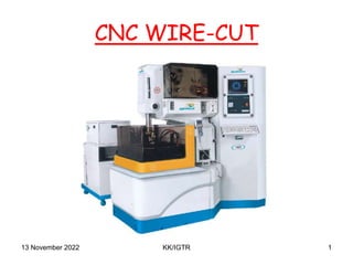
- 1. CNC WIRE-CUT 13 November 2022 1 KK/IGTR
- 2. Safety Rules • Always keep safety in mind. • Wear eye protection and safety shoes at all times. • Do not wear neckties, wristwatches, rings jewelry etc. • Wear half sleeve shirt. Long sleeve shirt will be rolled above the elbow. • Do not touch the wire while machine is in operation mode. • Do not keep any material on the table or U/V covers. • Make sure workpiece,Fixturing and table are properly grounded. • Never attempt to break wire with hands, use appropriate cutting device. • Do not watch the spark when skim cutting. • Do get thoroughly familiar with STOP button and other controls as well as alarms and interventions. • Clean machine and area after each use. 13 November 2022 2 KK/IGTR
- 3. Machine Start Procedure Stabilizer Switch On Green Switch On Machine Switch On Emergency Switch Release Power On 13 November 2022 3 KK/IGTR
- 4. 13 November 2022 4 KK/IGTR MACHINE SPECIFICATION
- 5. Working Principle ELECTRIC DISCHARGE MACHINING (EDM) is a process of repetitive sparking cycles. Graphical Representation of Sparking Cycles Inter electrode Gap Current Waveform During Sparking Where : TON : Pulse ON period TOFF : Pulse OFF period Td : Spark initiation period (Ignition Delay) VP : Open Gap Voltage Vg : Average Gap voltage IP : Machining peak current 13 November 2022 5 KK/IGTR
- 6. WEDM • Machine Tool:- • The machine tool comprises of a main work table (called as X-Y table), an auxiliary table (called as U-V table) and a wire drive mechanism. The workpiece is mounted and clamped on the main work table. The main table moves along X and Y axes, in steps of 0.5 micron, by means of servo motors, and also the U-V table moves, in steps of 0.5 micron, by means of servo motors. U & V axes are parallel to X & Y axes respectively. • A traveling wire which is continuously fed from wire feed spool is caused to travel through the workpiece and goes finally to the waste-wire box. Along its traveling path, the wire is supported under tension, between a pair of wire guides which are disposed on both (lower and upper) sides of the workpiece. Lower wire guide is stationary whereas the upper wireguide is supported by the U-V Table. The upper wireguide can be displaced transversely, along U-V axes, with respect to the lower wire guide. It can also be positioned vertically along Z axis by moving the vertical arm. 13 November 2022 6 KK/IGTR
- 7. WEDM • Power supply • The power supply unit comprises of Electric pulse generator, motor driver units for X, Y, U, V axes and CNC controller. • Dielectric Supply • While the machining is continued, the machining zone is continuously flushed with water passing through the nozzles on both sides of the workpiece. The spark discharge across the workpiece - wire electrodes causes ionization of the water which is used as a dielectric medium. • It is important to note that ionization of water leads to the increase in water conductivity. An ion exchange resin is used in dielectric distribution system, in order to prevent the increase in conductivity and to maintain the conductivity of the water constant. 13 November 2022 7 KK/IGTR
- 8. WEDM • Part Programming • The geometry of the profile and the motion of the wire-electrode tool along the profile is fed to the part programming system using keyboard. The profile geometry is defined in terms of various geometrical definitions of point, line and circle as the wire-tool path elements on graphical screen, by using a totally menu driven software. The wire compensation (for wire diameter and machining overcuts) and taper angle can be specified for the total path or for each path element separately. After the profile is fed to the computer, all the numerical information about the path is calculated automatically and its printout is generated. The entered profile can be verified on the graphic display screen and corrected, if necessary. After successful profile definition, the profile is recorded by the computer on a floppy disc which can be used in the controller for the execution. 13 November 2022 8 KK/IGTR
- 9. 13 November 2022 9 KK/IGTR
- 10. WEDM • WIRE ELECTRODE • The wire electrode is required to have a sufficient tensile strength and should be of uniform diameter and free from kink or twist. • The electrode wire material should be - • - Brass / Diffused Brass / Zinc coated Brass • - Diameter variation within ±0.002 mm • - Tensile strength more than 50 Kgf/mm2 • - Even winding, free from breaks/kinks. • 2.1 Wire diameter and Minimum corner radius. • Wire diameter of the wire imposes a restriction on the minimum achievable corner radius. (Refer Fig. 2.) • Minimum corner radius = (0.5 * diameter) + overcut. 13 November 2022 10 KK/IGTR
- 11. WEDM 13 November 2022 11 KK/IGTR
- 12. WEDM • Current carrying capacity of the wire. • As a thumb rule, a brass wire of 0.2 mm in diameter can pass a current of about 0.3 to 0.7 Amperes (A) in air, but, the same wire can easily pass a current of about 6 to 9 A in water. While machining, therefore, wire should always be surrounded by the water column to avoid wire breakage. • Wire Tension (WT) • Wire tension determines how much the wire is to be stretched between upper and lower wire guides. More the thickness of job, more is the tension required. Improper setting of tension may result in the job inaccuracies as well as wire breakage. Following chart gives nominal values of wire tension for different setting. Minimum tension (For 0 setting of WT) is approx. 200 ~ 300 gms. Which can be adjusted by clutch adjustment provided on feedspool mounting rod. This should be adjusted for different weight of spools. 13 November 2022 12 KK/IGTR
- 13. WEDM • WT TENSION (Gms.) Nominal Values • 1 300 • 2 420 • 3 540 • 4 660 • 5 780 • 6 900 • 7 1020 • 8 1140 • 9 1260 • 10 1380 13 November 2022 13 KK/IGTR
- 14. WEDM • Wire feed (WF) • Due to spark erosion, the traveling wire-electrode becomes thin and brittle. Wire feed is the rate at which the wire-electrode travels along the wire guide path. It is always desirable to set the wire feed to maximum. This will result in less wire breakage, better machining stability, and slightly more cutting speed. With wire feed set at 8 mt/min, on an average a 0.25 mm dia. brass wire spool of 5 kg will last for 24 sparking hours. • Setting WF at 15 will correspond to 15 mt/min (approx.) • Overcut • It is the lateral distance between the wire and workpiece during the sparking. • Overcut is larger if - • - machining gap voltage is higher • - discharge energy is higher • - wire tension is lower • - guide span is higher • - job thickness is higher • - dielectric conductivity is higher • - machining is unstable 13 November 2022 KK/IGTR 14
- 15. WEDM 13 November 2022 KK/IGTR 15 Wire Compensation (OFFSET) : Wire compensation = (0.5* wire diameter) + overcut Wire compensation can be to the left (G41) or right (G42) of profile depending upon the direction of motion and wire being inside or outside of profile as shown in figure .
- 16. WEDM • WATER DIELECTRIC • 1. CHARACTERIZATION & SUITABILITY TO WIRECUT EDM : • 1.1 The use of water as dielectric permits widening of spark gap to minimize short circuit, resulting in high cutting speed. • 1.2 Water has good wire electrode cooling effect (than kerosene, for example). • 1.3 It is non-flammable and its vapors are non-toxic. • 2. DIELECTRIC STRENGTH : • Since the insulation characterization of the dielectric fluid decides the overcut, it is imperative to keep the conductivity as constant as possible. During machining, the conductivity of dielectric water changes due to generation of metallic ions and dissolution of ambient gases. The conductivity can be decreased by passing the water through deionizer resin. This is done automatically by the machine. 13 November 2022 KK/IGTR 16
- 17. WEDM • FLUSHING : • Flushing is important to achieve a stable machining condition. It plays very important role as far as cutting speed is concerned. Both the Nozzles (upper and lower) should be just about 0.1 ~ 0.2 mm away from the workpiece, otherwise cutting performance drops considerably. Also both the nozzles should be checked periodically for damages. Scratches or slight damage on the contact edge affect cutting speed. Purity of the water should be maintained by timely replacement of filters. 13 November 2022 KK/IGTR 17
- 18. WEDM • SETTING UP AND OPERATION • 1. Job Mounting : • Mount the job and clamp it by maximum possible clamps. Dial the top surface of the job by dial gauge. The dial gauge stand can be mounted on the upper flushing assembly provision for the same is provided. Make the wire vertical with the help of verticality block provided along with the machine. • 2. Job Reference Point : • It is always desirable to have a reference point on the workpiece for setting the work co-ordinate system (WCS). The programming should be done with the reference to the WCS. The reference point can be defined by the ground edges of the workpiece or the center of a bored hole on the workpiece. 13 November 2022 KK/IGTR 18
- 19. WEDM 13 November 2022 KK/IGTR 19 Edge finding (EF) : This function should be used to find the edge for setting work co- ordinate system. Find the edge of the workpiece from a distance of 2 - 5 mm. Refer Figure. Remember that after edge finding, the wire center is away from the workpiece edge by a distance equal to wire radius.
- 20. WEDM • Center finding (CF) : • This function should be used to find the center of the reference hole. Center finding should be repeated at least twice to verify consistency. • Following care should be taken to perform CF and EF functions. • 2.2.1 Workpiece surface should be free from moisture, rust, dust and grease etc. • 2.2.2 Upper flushing assembly should not be wet • 2.2.3 WF should be at 3 and WT at 6 13 November 2022 KK/IGTR 20
- 21. WEDM (A) Machining Parameters:- • TON : Pulse ON Time • TOFF : Pulse OFF Time. • IP : Peak current (A). • VP : Pulse Peak Voltage setting • WP : Flushing Pressure of Water Dielectric • WF : Wire Feed rate setting. • WT : Wire Tension setting • SV : Spark Gap Set Voltage • SF : Servo Feed Setting • T : Threshold setting • CC : Corner Control factor • CRK : Radius compensation factor • CS% : Cutting Speed Over-ride %. • C DWELL : This parameter is used to provide Dwell (delay) in seconds 13 November 2022 KK/IGTR 21
- 22. 13 November 2022 KK/IGTR 22
- 23. 13 November 2022 KK/IGTR 23
- 24. 13 November 2022 KK/IGTR 24
- 25. 13 November 2022 KK/IGTR 25
- 26. 13 November 2022 KK/IGTR 26
- 27. 13 November 2022 KK/IGTR 27
- 28. 13 November 2022 KK/IGTR 28
- 29. 13 November 2022 KK/IGTR 29
- 30. 13 November 2022 KK/IGTR 30
- 31. 13 November 2022 KK/IGTR 31
- 32. 13 November 2022 KK/IGTR 32
- 33. 13 November 2022 KK/IGTR 33
- 34. Advantages • Complex shapes that would otherwise be difficult to produce with conventional cutting tools. • Extremely hard material to very close tolerances. • Very small work pieces where conventional cutting tools may damage the part from excess cutting tool pressure. • There is no direct contact between tool and work piece. Therefore delicate sections and weak materials can be machined without any distortion. • A good surface finish can be obtained. • Very fine holes can be easily produced. • The part produced are burr free. 13 November 2022 34 KK/IGTR
- 35. Disadvantages • Power consumption is high. • Electrically non-conductive materials can’t be machined. • Only through profiles can be machined. 13 November 2022 35 KK/IGTR
- 36. Application • Punches and dies used in Press Tool can be made. • For the production of moulds and dies. • Used to cut out complex contours in electrically conductive workpieces. • Cylindrical pins as small as 5mm in diameter can be machined.