Boiler feed and pump sizing c-b and grundfos july 2016(1)lorenzo Monasca
Presentacion realizada por la empresa Cleaver Brooks y Grundfos
Pasos a seguir de como seleccionar una bomba de agua de alimentacion a una caldera de media presion.
Accumulation and Over-pressure: difference between accumulation and overpressureVarun Patel
Accumulation is pressure above the maximum allowable working pressure that vessel experience during high pressure event. Hence, when we say ‘accumulation’, its mean we are talking about the vessel or equipment.
On the other hand, Overpressure is pressure above the set pressure of the pressure safety valve that PSV experience during high pressure event. Hence, when we say ‘accumulation’, its mean we are talking about the pressure relief valve.
The most popular Thai magazine in the field of Mechanical, Electrical and Industrial Engineering. Technic Magazine is printed in Thailand and distributed throughout Thailand since 1984.
MORE INFORMATION: www.me.co.th
A Brief Introduction to Industrial boiler. And details about Boiler of Monnet Power Company Ltd(2X525 MW) Thermal Power Plant. Details about parts of Boiler, Water & Steam path, Oil Circuit, flue Gas Circuit.
Boiler purge is the basic process of resetting boiler before lightup. This presentation explains the logic, schematics & working of purge procedure. For enhanced knowledge of this topic, I can be reached at tahoorkhn03@gmail.com.
Water steam Circuit in Supercritical Boiler for 660MW Power PlantHareesh VS
An animated presentation over Complete water steam circulation in a super critical boiler with flow chart. The water-steam path through various Systems (High pressure & Low pressure systems) in boiler for a 660MW thermal power plat, and also indicates the temperature and pressure variations after flowing through individual systems. Watch Live Presentation on YouTube: http://youtu.be/snIVrTmI4bM
This Presentation is about the basic fundamentals one needs to know to begin Piping Engineering. All the basic formulas and questions that are usually asked in interviews are answered in this presentation. Feel free to ask any doubts in the comments and iI may try my best to answer them for you.
small notes on boiler,
THIS IS THE SMALL PPT ON BOILER ,
THE BOILER IS OF 2TYPES
1.FIRE TUBE
2.WATER TUBE
FIRE TUBE:
FIRE IS SURROUNDED BY WATER AND MAX PRESS IS 17.5KG/CM2, 12TONN/HR
WATER TUBE:
WATER IS SURROUNDED BY FIRE AND IS USED IN MAINLY IN POWER PLANTS AND HIGH USED STEM PROCESS INDUSTRIES..
Toyota 8TB50 Pallet Truck Service Repair Manualuhjekm ioelpoe
This is the Highly Detailed factory service repair manual for theTOYOTA 8TB50 PALLET TRUCK, this Service Manual has detailed illustrations as well as step by step instructions,It is 100 percents complete and intact. they are specifically written for the do-it-yourself-er as well as the experienced mechanic.TOYOTA 8TB50 PALLET TRUCK Service Repair Workshop Manual provides step-by-step instructions based on the complete dis-assembly of the machine. It is this level of detail, along with hundreds of photos and illustrations, that guide the reader through each service and repair procedure. Complete download comes in pdf format which can work under all PC based windows operating system and Mac also, All pages are printable. Using this repair manual is an inexpensive way to keep your vehicle working properly.
Service Repair Manual Covers:
General Information
Safety
Systems Overview
Planned Maintenance
Troubleshooting
Messages and Codes
Component Procedures
Theory of Operation
Appendix
Index
Wire Diagrams
Parts Catalog
File Format: PDF
Compatible: All Versions of Windows & Mac
Language: English
Requirements: Adobe PDF Reader
NO waiting, Buy from responsible seller and get INSTANT DOWNLOAD, Without wasting your hard-owned money on uncertainty or surprise! All pages are is great to haveTOYOTA 8TB50 PALLET TRUCK Service Repair Workshop Manual.
Looking for some other Service Repair Manual,please check:
https://www.aservicemanualpdf.com/
Thanks for visiting!
Bls-series Double-Acting Climbing Jacks include integral tilt saddles with maximum tilt angles up to 5˚ and large base with anti-rotation rod for stability.
Enterprise Excellence is Inclusive Excellence.pdfKaiNexus
Enterprise excellence and inclusive excellence are closely linked, and real-world challenges have shown that both are essential to the success of any organization. To achieve enterprise excellence, organizations must focus on improving their operations and processes while creating an inclusive environment that engages everyone. In this interactive session, the facilitator will highlight commonly established business practices and how they limit our ability to engage everyone every day. More importantly, though, participants will likely gain increased awareness of what we can do differently to maximize enterprise excellence through deliberate inclusion.
What is Enterprise Excellence?
Enterprise Excellence is a holistic approach that's aimed at achieving world-class performance across all aspects of the organization.
What might I learn?
A way to engage all in creating Inclusive Excellence. Lessons from the US military and their parallels to the story of Harry Potter. How belt systems and CI teams can destroy inclusive practices. How leadership language invites people to the party. There are three things leaders can do to engage everyone every day: maximizing psychological safety to create environments where folks learn, contribute, and challenge the status quo.
Who might benefit? Anyone and everyone leading folks from the shop floor to top floor.
Dr. William Harvey is a seasoned Operations Leader with extensive experience in chemical processing, manufacturing, and operations management. At Michelman, he currently oversees multiple sites, leading teams in strategic planning and coaching/practicing continuous improvement. William is set to start his eighth year of teaching at the University of Cincinnati where he teaches marketing, finance, and management. William holds various certifications in change management, quality, leadership, operational excellence, team building, and DiSC, among others.
The world of search engine optimization (SEO) is buzzing with discussions after Google confirmed that around 2,500 leaked internal documents related to its Search feature are indeed authentic. The revelation has sparked significant concerns within the SEO community. The leaked documents were initially reported by SEO experts Rand Fishkin and Mike King, igniting widespread analysis and discourse. For More Info:- https://news.arihantwebtech.com/search-disrupted-googles-leaked-documents-rock-the-seo-world/
Taurus Zodiac Sign_ Personality Traits and Sign Dates.pptxmy Pandit
Explore the world of the Taurus zodiac sign. Learn about their stability, determination, and appreciation for beauty. Discover how Taureans' grounded nature and hardworking mindset define their unique personality.
Unveiling the Secrets How Does Generative AI Work.pdfSam H
At its core, generative artificial intelligence relies on the concept of generative models, which serve as engines that churn out entirely new data resembling their training data. It is like a sculptor who has studied so many forms found in nature and then uses this knowledge to create sculptures from his imagination that have never been seen before anywhere else. If taken to cyberspace, gans work almost the same way.
Discover the innovative and creative projects that highlight my journey throu...dylandmeas
Discover the innovative and creative projects that highlight my journey through Full Sail University. Below, you’ll find a collection of my work showcasing my skills and expertise in digital marketing, event planning, and media production.
"𝑩𝑬𝑮𝑼𝑵 𝑾𝑰𝑻𝑯 𝑻𝑱 𝑰𝑺 𝑯𝑨𝑳𝑭 𝑫𝑶𝑵𝑬"
𝐓𝐉 𝐂𝐨𝐦𝐬 (𝐓𝐉 𝐂𝐨𝐦𝐦𝐮𝐧𝐢𝐜𝐚𝐭𝐢𝐨𝐧𝐬) is a professional event agency that includes experts in the event-organizing market in Vietnam, Korea, and ASEAN countries. We provide unlimited types of events from Music concerts, Fan meetings, and Culture festivals to Corporate events, Internal company events, Golf tournaments, MICE events, and Exhibitions.
𝐓𝐉 𝐂𝐨𝐦𝐬 provides unlimited package services including such as Event organizing, Event planning, Event production, Manpower, PR marketing, Design 2D/3D, VIP protocols, Interpreter agency, etc.
Sports events - Golf competitions/billiards competitions/company sports events: dynamic and challenging
⭐ 𝐅𝐞𝐚𝐭𝐮𝐫𝐞𝐝 𝐩𝐫𝐨𝐣𝐞𝐜𝐭𝐬:
➢ 2024 BAEKHYUN [Lonsdaleite] IN HO CHI MINH
➢ SUPER JUNIOR-L.S.S. THE SHOW : Th3ee Guys in HO CHI MINH
➢FreenBecky 1st Fan Meeting in Vietnam
➢CHILDREN ART EXHIBITION 2024: BEYOND BARRIERS
➢ WOW K-Music Festival 2023
➢ Winner [CROSS] Tour in HCM
➢ Super Show 9 in HCM with Super Junior
➢ HCMC - Gyeongsangbuk-do Culture and Tourism Festival
➢ Korean Vietnam Partnership - Fair with LG
➢ Korean President visits Samsung Electronics R&D Center
➢ Vietnam Food Expo with Lotte Wellfood
"𝐄𝐯𝐞𝐫𝐲 𝐞𝐯𝐞𝐧𝐭 𝐢𝐬 𝐚 𝐬𝐭𝐨𝐫𝐲, 𝐚 𝐬𝐩𝐞𝐜𝐢𝐚𝐥 𝐣𝐨𝐮𝐫𝐧𝐞𝐲. 𝐖𝐞 𝐚𝐥𝐰𝐚𝐲𝐬 𝐛𝐞𝐥𝐢𝐞𝐯𝐞 𝐭𝐡𝐚𝐭 𝐬𝐡𝐨𝐫𝐭𝐥𝐲 𝐲𝐨𝐮 𝐰𝐢𝐥𝐥 𝐛𝐞 𝐚 𝐩𝐚𝐫𝐭 𝐨𝐟 𝐨𝐮𝐫 𝐬𝐭𝐨𝐫𝐢𝐞𝐬."
Accpac to QuickBooks Conversion Navigating the Transition with Online Account...PaulBryant58
This article provides a comprehensive guide on how to
effectively manage the convert Accpac to QuickBooks , with a particular focus on utilizing online accounting services to streamline the process.
3.0 Project 2_ Developing My Brand Identity Kit.pptxtanyjahb
A personal brand exploration presentation summarizes an individual's unique qualities and goals, covering strengths, values, passions, and target audience. It helps individuals understand what makes them stand out, their desired image, and how they aim to achieve it.
Business Valuation Principles for EntrepreneursBen Wann
This insightful presentation is designed to equip entrepreneurs with the essential knowledge and tools needed to accurately value their businesses. Understanding business valuation is crucial for making informed decisions, whether you're seeking investment, planning to sell, or simply want to gauge your company's worth.
Falcon stands out as a top-tier P2P Invoice Discounting platform in India, bridging esteemed blue-chip companies and eager investors. Our goal is to transform the investment landscape in India by establishing a comprehensive destination for borrowers and investors with diverse profiles and needs, all while minimizing risk. What sets Falcon apart is the elimination of intermediaries such as commercial banks and depository institutions, allowing investors to enjoy higher yields.
Affordable Stationery Printing Services in Jaipur | Navpack n PrintNavpack & Print
Looking for professional printing services in Jaipur? Navpack n Print offers high-quality and affordable stationery printing for all your business needs. Stand out with custom stationery designs and fast turnaround times. Contact us today for a quote!
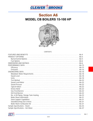
4. Section A6
FEATURES AND BENEFITS
In addition to the features provided on all Cleaver-Brooks Firetube Boilers, the
following features apply specifically to Model CB Firetube Boilers. The CB four-pass
dryback boiler is the premium firetube boiler design available.
Four-Pass Dryback Design:
• Four-pass design provides high flue gas velocities and low stack temperature for
guaranteed maximum efficiency.
• Dryback design provides full access to boiler tubes, tube sheet, and furnace for
ease of maintenance.
• Dryback design includes single rear tube sheet construction, providing reduced
tube sheet stresses.
Five Square Feet of Heating Surface per Boiler hp:
• Maximum heat transfer with minimum thermal stresses provide guaranteed
efficiency and long boiler life.
• Highest guaranteed fuel-to-steam efficiencies.
Low Furnace Location
• Furnace located well below water level with generous clearance from bottom of
boiler, allowing proper circulation.
• Low furnace provides additional safety margin between furnace and water level.
• Reduces water carryover, producing drier steam.
Hinged or Davited Front and Rear Doors:
• Provides full access to front and rear tube sheet and furnace.
• Reduces maintenance costs.
High Turndown Burner:
• 4:1 turndown (gas and oil) is standard.
• Advanced burner design provides maximum combustion efficiencies and high
turndown.
• Reduced boiler cycling and maintenance.
• Boiler stays on line during low load conditions for optimum efficiency and
performance.
Gas, No. 2 Oil, No. 6 Oil, and Combination Gas and Oil Burners Available:
• High radiant multi-port gas burner designed for high gas velocities and complete
fuel/air mixing, providing maximum combustion efficiencies.
• Air atomizing oil burner available for proper oil atomization, maximum
combustion efficiency, and low maintenance requirements.
• Air atomizing compressor provided with the boiler package for clean oil burning
and ease of maintenance.
• Combination gas/oil burners provide quick fuel changeover without re-
adjustment of the burner.
• Fuel oil controller eliminates the need for over 40 connections, combining
gauges, valves, and regulators into a single casting.
• Retractable oil nozzle provides easy access and cleaning and eliminates coking
of oil and nozzle tip when firing gas.
A6-4
03-08
5. Section A6
PRODUCT OFFERING
Model CB Firetube Boilers are available in low pressure steam, high pressure steam,
and hot water designs. Burners are available to fire natural gas, light oil, heavy oil,
or a combination of oil and gas. Optional alternate fuel burners are also available.
Model CB Boilers include:
• Four-pass dryback design.
• 15 hp through 100 hp.
• 150 psig - 350 psig high pressure steam.
• 15 psig low pressure steam.
• 30 psig or 125 psig hot water.
• Natural gas, light oil, or heavy oil firing.
The Model CB Boiler is the premium firetube product offering providing maximum
boiler efficiency, the widest range of size and pressures, and premium control
packages.
Available options: For option details, contact your Cleaver-Brooks authorized
representative. Options include the following:
Boiler Options
• Auxiliary low water cut-off (standard on steam boilers).
• Drain valves.
• Additional screwed or flanged tappings.
• Special design pressures.
• Surge load baffles.
• Seismic design.
• Internal hot water coils.
• Blowdown valves.
• Non-return valves.
• Feedwater valves and regulators.
• Special doors, davited, hinged, left swing.
• Special base rails.
• Surface blowdown systems.
• Combustion relief door.
• Weather-proofing.
• Blend pump.
Burner/Control • Special modulation controls.
Options • Optional flame safeguard controller.
• Lead/lag system.
• High altitude design, up to 12,000 ft.
• Special insurance and code requirements (e.g. FM, ASME CSD-1).
• Alarm bell/silence switch.
• Special motor requirements (TEFC, high efficiency).
A6-5
03-08
6. Section A6
• Remote contacts.
• Special purpose indicator lights.
• Main disconnect.
• Elapsed time meter.
• Voltmeter/micro-ammeter.
• NEMA enclosures.
• Low fire hold controls.
• Remote emergency shut-off (115V).
• Circuit breaker.
• Day/night controls.
• Special power requirements.
Fuel Options • Automatic fuel changeover.
• Special gas pressure regulator.
• Oversized/undersized gas trains.
• Gas strainer.
• Special fuel shut-off valves.
• Special pilot.
• Alternate fuel firing (propane, digester gas, etc.).
• Special oil pumps.
DIMENSIONS AND RATINGS
• Dimensions and ratings for the Model CB boilers are shown in the following
tables and illustrations:
• Table A6-1. Model CB Steam Boiler Ratings (15 thru 100 hp)
• Table A6-2. Model CB Hot Water Boiler Ratings (15 thru 100 hp)
• Table A6-3. Safety Valve Openings
• Table A6-4. Relief Valve Openings
• Figure A6-1. Model CB Steam Boiler Dimensions (15 and 150 lb design
pressure) (15 thru 100 hp)
• Figure A6-2 Model CB Hot Water Boiler Dimensions (15 and 150 lb design
pressure) (15 thru 100 hp)
• Figure A6-3. Space Required to Open Rear Head on Model CB Boilers
Equipped with Davits
• Figure A6-4. Model CB Boiler Mounting PiersL
• Figure A6-5. Lifting Lug Locations, Model CB Boilers
A6-6
03-08
7. Section A6
Table A6-1. Model CB Steam Boiler Ratings (15 - 100 hp)
BOILER HP 15C 20C 30C 40C 50 60 70 80 100
RATINGS - SEA LEVEL TO 3000 FT
Rated Cap. (lbs steam/hr @212°F) 518 690 1035 1380 1725 2070 2415 2760 3450
Btu Output (1000 Btu/hr) 502 670 1004 1339 1674 2009 2343 2678 3348
APPROXIMATE FUEL CONSUMPTION AT RATED CAPACITY
Light Oil (gph)A 4.5 6.0 9.0 12.0 15.0 18.0 21.0 24.0 30.0
Heavy Oil (gph) B - - - - 14.0 16.5 19.5 22.5 28.0
Gas (cfh) 1000 Btu-Nat 625 835 1255 1675 2095 2510 2930 3350 4185
Gas (Therm/hr) 6.3 8.4 12.6 16.8 21.0 25.1 29.3 33.5 41.9
POWER REQUIREMENTS - SEA LEVEL TO 3000 FT, 60 HZ
Blower Motor hp (except gas) 1 1 1-1/2 2 2 2 2 2D 3
Gas Models (only) 1 1 1-1/2 2 2 2 2 2 D 3
Oil Pump Motor, hp No. 2 Oil Belt-Driven From Blower 1/3 1/3 1/3 1/3 1/3
Oil Pump Motor, hp No. 6 Oil - - - - 1/3 1/3 1/3 1/3 1/3
Oil Heater kW No. 6 Oil - - - - 5 5 5 5 5
Air Compressor Motor hp Air Compressor Belt-Driven 2 2 2 2 2
(Oil firing Only) from Blower Motor
NOTES:
1. For altitudes above 3000 ft, contact your local Cleaver-Brooks authorized representative for verification of blower motor hp.
A. Based on 140,000 Btu/gal.
B. Based on 150,000 Btu/gal.
C. No. 6 Oil not available in 15-40 hp range.
D. 3 hp above 2000 ft.
Table A6-2. Model CB Hot Water Boiler Ratings (15 - 100 hp)
BOILER HP 15c 20c 30c 40c 50 60 70 80 100A 100 125A
RATINGS - SEA LEVEL TO 3000 FT
Rated Cap Btu Output (1000 Btu/ 502 670 1004 1339 1674 2009 2343 2678 3348 3348 4184
hr)
APPROXIMATE FUEL CONSUMPTION AT RATED CAPCITY
Light Oil (gph) A 4.5 6.0 9.0 12.0 15.0 18.0 21.0 24.0 30.0 30.0 37.5
Heavy Oil (gph)B - - - - 14.0 16.5 19.5 22.5 28.0 28.0 35.0
Gas (cfh) 5230
MBtu- nat 625 835 1255 1675 2095 2510 2930 3350 4185 4185 52.3
Gas (Therm/hr) 6.3 8.4 12.6 16.8 21.0 25.1 29.3 33.5 41.9 41.9
POWER REQUIREMENTS - SEA LEVEL TO 3000 FT, 60 HZ
Blower Motor hp (except gas) 1 1 1-1/2 2 2 2 2 2D 3 3 3
Gas Models (only) 1 1 1-1/2 2 2 2 2 2D 3 3 3
Oil Pump Motor, hp No. 2 Oil Belt-Driven From Blower 1/3 1/3 1/3 1/3 1/3 1/3 1/2
Oil Pump Motor, hp No. 6 Oil - - - - 1/3 1/3 1/3 1/3 1/3 1/3 1/2
Oil Heater kW No. 6 Oil - - - - 5 5 5 5 5 5 5
Air Compressor Motor hp Air Compressor Belt-Driven 2 2 2 2 2 2 2
(Oil firing Only) from Blower Motor
NOTES:
1. For altitudes above 3000 ft, contact your local Cleaver-Brooks authorized representative for verification of blower motor hp.
A. Based on 140,000 Btu/gal.
B. Based on 150,000 Btu/gal.
C. No. 6 Oil not available in 15-40 hp range.
D. 3 hp above 2000 ft.
A6-7
03-08
9. Section A6
BOILER HP DIM 15 20 30 40 50 60 70 80 100
LENGTHS
Overall A 96-5/8 96-5/8 114-5/8 140-5/8 129 129 168 168 187
Shell B 62-5/8 62-5/8 80-5/8 106-5/8 92 92 131 131 150
Base Frame C 59 59 77 103 91 91 130 130 148
Front Head Extension D 18-1/2 18-1/2 18-1/2 18-1/2 18-1/2 18-1/2 18-1/2 18-1/2 18-1/2
Rear Head Extension E 15-1/2 15-1/2 15-1/2 15-1/2 18-1/2 18-1/2 18-1/2 18-1/2 18-1/2
Front Ring Flange to F 36 36 45 57 46 46 65-1/2 65-1/2 75
Nozzle - 15 psig
Front Ring Flange to Nozzle - 150 psig F 36 36 45 57 46 46 72-1/2 72-1/2 82
Ring Flange to Base G 1-13/16 1-13/16 1-13/16 1-13/16 5/8 1/2 1/2 1/2 1/2
WIDTHS
Overall I 61 61 61 61 73 73 73 73 73
ID, Boiler J 36 36 36 36 48 48 48 48 48
Center to Water Column K 33 33 33 33 39 39 39 39 39
Center to Outside Hinge KK 22 22 22 22 29 29 29 29 29
Center to Lagging L 20 20 20 20 27 27 27 27 27
Center to Auxiliary LWCO LL 28 28 28 28 34 34 34 34 34
Base, Outside M 28 28 28 28 37-5/8 37-3/8 37-3/8 37-3/8 37-3/8
Base, Inside N 22 22 22 22 29-5/8 29-5/8 29-5/8 29-5/8 29-5/8
Figure A6-1. Model CB Steam Boiler Dimensions and Weights (15 and 150 psig Design Pressure -
15 to 100 hp) Sheet 1 of 2
A6-9
03-08
10. Section A6
BOILER HP DIM 15 20 30 40 50 60 70 80 100
HEIGHTS
Base to Steam Outlet (15 psig only) PL 50-1/4 50-1/4 50-1/4 50-1/4 70-5/16 70-5/16 70-5/16 70-5/16 70-5/16
Overall OO 66 66 66 66 78-3/4 78-3/4 78-3/4 78-3/4 78-3/4
Base to Vent Outlet O 53-1/2 53-1/2 53-1/2 53-1/2 70 70 70 70 70
Base to Steam Outlet (150 psig only) PH 50-1/4 50-1/4 50-1/4 50-1/4 66-31/2 66-1/2 66-1/2 66-1/2 70-5/16
Height of Base Q 8 8 8 8 12 12 12 12 12
Base to Bottom of Boiler R 12 12 12 12 16 16 16 16 16
BOILER CONNECTIONS
Chemical Feed H 1 1 1 1 1 1 1 1 1
Feedwater, Right and Left S 1 1 1 1 1-1/4 1-1/4 1-1/4 1-1/4 1-1/4
Low Pressure (15 psig only)
Steam Nozzle U 4 4 4 6A 6A 6A 6A 6A 8A
Drain, Front and Rear W 1 1 1 1-1/4 1-1/4 1-1/4 1-1/2 1-1/2 1-1/2
High Pressure (150 psig only)
Surface Blowoff, Top CL T 1 1 1 1 1 1 1 1 1
Steam Nozzle Y 1-1/2 1-1/2 2 2 3 3 3 3 4B
Blowdown, Front and Rear W 1 1 1 1 1-1/4 1-1/4 1-1/4 1-1/4 1-1/4
VENT STACK
Diameter (flgd connection) BB 6 6 8 8 10 10 12 12 12
Front Ring Flange to Vent CL CC 4 4 5 5 6 6 7 7 7
MINIMUM CLEARANCES
Rear Door SwingC DD 44 44 44 44 55 55 55 55 55
Front Door Swing C EE 44 44 44 44 55 55 55 55 55
Tube Removal, Rear FF 56 56 74 100 84 84 123 123 142
Tube Removal, Front GG 46 46 64 90 74 74 113 113 132
MINIMUM BOILER ROOM LENGTH ALLOWING FOR DOOR SWING AND TUBE REMOVAL FROM:
Rear of Boiler RR 163 163 199 251 231 231 309 309 347
Front of Boiler RF 153 153 189 241 221 221 299 299 337
Thru Window or Doorway RD 151 151 169 195 202 202 241 241 260
WEIGHT IN LBS
Normal Water Capacity 1340 1300 1710 2290 3130 2920 4620 4460 5088
Approx. Ship Wgt - 15 psig 3000 3100 3650 4350 6900 7000 8100 8200 9000
Approx. Ship Wgt - 150 psig 3100 3200 3800 4500 7000 7200 8800 9000 9500
Approx. Ship Wgt - 200 psig 3300 3400 4100 4700 7400 7600 9300 9500 10000
NOTES:
1. Air compressor belt driven from blower motor on sizes 15 thru 40
2. Air compressor module on sizes 50 thru 100 hp.
3. Accompanying dimensions, while sufficiently accurate for layout purposes, must be confirmed for construction by certified dimension prints.
A. ANSI 150 psig flange.
B. ANSI 300 psig flange.
C. 15 thru 100 hp standard hinged door.
Figure A6-1. Model CB Steam Boiler Dimensions and Weights (15 and 150 psig Design Pressure - 15 to 100 hp)
Sheet 2 of 2
A6-10
03-08
11. Section A6
BOILER HP DIM 15 20 30 40 50 60 70 80/ 100A 100/
125A
LENGTHS
Overall A 97 97 114-5/8 140-5/8 129 129 168 168 187
Shell B 62-5/8 62-5/8 80-5/8 106-5/8 92 92 131 131 150
Base Frame C 59 59 77 103 91 91 130 130 148
Front Head Ext. D 18-1/2 18-1/2 18-1/2 18-1/2 18-1/2 18-1/2 18-1/2 18-1/2 18-1/2
Rear Head Ext. E 15-1/2 15-1/2 15-1/2 15-1/2 18-1/2 18-1/2 18-1/2 18-1/2 18-1/2
Front Ring Flange to Return F 43-5/8 43-5/8 62 81 69 69 108 108 127
Front Ring Flange to Outlet G 55-1/8 55-1/8 73-1/8 98-1/2 84-5/8 84-5/8 123-5/8 123-5/8 142-5/8
Ring Flange to Base H 1-13/16 1-13/16 1-13/16 1-13/16 5/8 5/8 5/8 5/8 1
WIDTHS
Overall I 48-3/4 48-3/4 48-3/4 48-3/4 63 63 63 63 63
ID, Boiler J 36 36 36 36 48 48 48 48 48
Center to Entrance Box K 28-3/4 28-3/4 28-3/4 28-3/4 36 36 36 36 36
Center to Outside Hinge KK 22 22 22 22 29 29 29 29 29
Center to Lagging L 20 20 20 20 27 27 27 27 27
Base, Outside M 28 28 28 28 37-5/8 37-5/8 37-5/8 37-5/8 37-5/8
Base, Inside N 22 22 22 22 29-5/8 29-5/8 29-5/8 29-5/8 29-5/8
Figure A6-2. Model CB Hot Water Boiler Dimensions (30 psig and 125 psig Design Press. - 15 to 100 hp)
Sheet 1 of 2
A6-11
03-08
12. Section A6
BOILER HP DIM 15 20 30 40 50 60 70 80/ 100A 100/
125A
HEIGHTS
Overall OO 66 66 66 66 72-5/8 72-5/8 72-5/8 72-5/8 72-5/8
Base to Vent Outlet O 53-1/2 53-1/2 53-1/2 53-1/2 70 70 70 70 70
Base to Return and outlet P 50 50 50 50 70-5/16 70-5/16 70-5/16 70-5/16 70-5/16
Davit (Front) DF - - - - - - - - -
Davit (Rear) DR - - - - - - - - -
Height of Base Q 8 8 8 8 12 12 12 12 12
Base to bottom of boiler R 12 12 12 12 16 16 16 16 16
BOILER CONNECTION
Waterfill Conn. Right & Left S 1 1 1 1 1-1/4 1-1/4 1-1/4 1-1/4 1-1/4
Water Return - Threaded T 2-1/2 2-1/2 3 3 4 4 4 4 4
Water Outlet - Threaded A U 2-1/2 2-1/2 3 3 4 4 4 4 4
Air Vent v 1 1 1 1 1-1/4 1-1/4 1-1/4 1-1/4 1-1/4
Drain, Front and Rear W 1 1 1 1-1/4 1-1/4 1-1/4 1-1/2 1-1/2 1-1/2
Auxiliary Connection X 1 1 1 1 1 1 1 1 1
VENT STACK
Diameter (flgd. connection) BB 6 6 8 8 10 10 12 12 12
Front Ring Flange to vent CL CC 4 4 5 5 6 6 7 7 7
MINIMUM CLEARANCES
Rear Door Swing DD 44 44 44 44 55 55 55 55 55
Front Door Swing EE 44 44 44 44 55 55 55 55 55
Tube Removal, Rear FF 56 56 74 100 84 84 123 123 142
Tube, Removal, Front GG 46 46 64 90 74 74 113 113 132
MINIMUM BOLER ROOM LENGTH ALLOWING FOR DOOR SWING AND TUBE REMOVAL FROM:
Rear of Boiler RR 163 163 199 251 231 231 309 309 347
Front of Boiler RF 153 153 189 241 221 221 299 299 337
Thru Window or Doorway RD 151 151 169 195 202 202 241 241 260
WEIGHT IN LBS
Water Capacity Flooded 1500 1460 1915 2585 3665 3500 5420 5250 5960
Approx. Ship. Wgt. – 30 psig 3000 3100 3650 4350 6800 7000 8000 8100 8800
Approx. Ship. Wgt. – 125 psig 3300 3400 3880 4580 7100 7300 8350 8450 9150
NOTES:
1. Accompanying dimensions and ratings while sufficiently accurate for layout purposes, must be confirmed for construction
by certified dimension prints.
2. Air compressor belt driven from blower motor on sizes 15 thru 40 hp.
3. Air compressor module on sizes 50 thru 100 hp.
4. 15 - 100 hp, hinged door standard.
5. Add 370lbs to the 80 hp ship weight for 100A and 485 lbs to the 100 hp ship weight for the 125A.
A. Dip Tube included.
Figure A6-2. Model CB Hot Water Boiler Dimensions (30 psig Design Pressure -
15 to 100 hp) - Sheet 2 of 2
A6-12
03-08
13. Section A6
BOILER HP DIMENSION (INCHES)
A B C D E
15 - 40, 50A 20 36 28 45 20 PLAN VIEW
50 - 100, 100A, 125A 27 48 38 60 26
NOTE:
1. Dimensions in inches.
2. 15 - 100 hp (100A & 125A)
boilers are standardly equipped with hinges. Davit available as an
option.
Figure A6-3. Space Required to Open Rear Head on Model CB Boilers Equipped with Davits
BOILER HP A B C D E F G X1 X2
15-20 6 8 59 17 33 3 22 9-3/4 9-3/4
25-30 6 8 77 17 33 3 22 9-3/4 9-3/4
40-50A 6 8 103 17 33 3 22 9-3/4 9-3/4
50-60 6 8 91 26 42 4 29-5/8 8-1/4 8-1/4
70-80, 100A 6 8 130 26 42 4 29-5/8 8-1/4 8-1/4
100, 125A 6 8 148 26 42 4 29-5/8 8-1/4 8-1/4
NOTE:
1. All numbers in table are in inches.
2. 6-inch high mounting piers recommended for use beneath the boiler base frame. The use of these piers provides increased inspection ac-
cessibility to the piping beneath the boiler and added height for washing down the area beneath the boiler.
Figure A6-4. Model CB Boiler Mounting Piers
A6-13
03-08
14. Section A6
FRONT B C E DIA. HOLE
FLANGE
CL
VIEW A
A
NEAR FAR
D SIDE SIDE
D
VIEW B
BOILER HP VIEW ALL DIMENSIONS IN INCHES
A B C D E
15 Steam A 51-3/4 12 38-3/4 - 2-1/2
Hot Water B 50-1/2 12 38-3/4 6 2-1/2
20 Steam A 51-3/4 12 38-3/4 - 2-1/2
Hot Water B 50-1/2 12 38-3/4 6 2-1/2
25 Steam A 51-3/4 12 56-3/4 - 2-1/2
Hot Water B 50-1/2 12 56-3/4 6 2-1/2
30 Steam A 51-3/4 12 56-3/4 - 2-1/2
Hot Water B 50-1/2 12 56-3/4 6 2-1/2
40 Steam A 51-3/4 12 82-3/4 - 2-1/2
Hot Water B 50-1/2 12 82-3/4 6 2-1/2
50A
Water B 50-1/2 12 82-3/4 6 2-1/2
50 All B 68 18 57 10 2-1/2
60 All B 68 18 57 10 2-1/2
70 All B 68 27 67 10 2-1/2
80 All B 68 27 67 10 2-1/2
100 All B 68 27 86 10 2-1/2
100A Hot Water B 68 27 67 10 2-1/2
NOTE:
1. A, B and C Dimensions may vary by 1/2 inch.
2. BHP followed by “A” designates hot water boilers furnished in a smaller vessel size with additional tubes in upper portion of vessel.
Figure A6-5. Lifting Lug Locations, Model CB Boilers
A6-14
03-08
15. Section A6
PERFORMANCE DATA
Efficiency Tables A6-5 through A6-10 show predicted fuel-to-steam efficiencies (including
radiation and convection losses) for Cleaver-Brooks Model CB Firetube boilers. For
specific efficiencies on firetube boiler offerings not listed here, contact your local
Cleaver-Brooks authorized representative.
Cleaver-Brooks offers an industry leading fuel-to-steam boiler efficiency guarantee
for Model CB Firetube Boilers. The guarantee is based on the fuel-to-steam
efficiencies shown in the efficiency tables and the following conditions. The
efficiency percent number is only meaningful if the specific conditions of the
efficiency calculations are clearly stated in the specification (see Cleaver-Brooks
publication CB-7768 for a detailed description of efficiency calculations).
The boiler manufacturer shall guarantee that, at the time of startup, the boiler will
achieve fuel-to-steam efficiency (as shown in the tables listed above) at 100% firing
rate (add efficiency guarantees at 25%, 50%, and 75% of rating, if required). If the
boiler(s) fail to achieve the corresponding guaranteed efficiency as published, the
boiler manufacturer will rebate, to the ultimate boiler owner, five thousand dollars
($5,000) for every full efficiency point (1.0%) that the actual efficiency is below the
guaranteed level. The specified boiler efficiency is based on the following conditions.
1. Fuel specification used to determine boiler efficiency:
• Natural Gas
Carbon, % (wt) = 69.98
Hydrogen, % (wt) = 22.31
Sulfur, % (wt) = 0.0
Heating value, Btu/lb = 21,830
• No. 2 Oil
Carbon, % (wt) = 85.8
Hydrogen, % (wt) = 12.7
Sulfur, % (wt) = 0.2
Heating value, Btu/lb = 19,420
• No. 6 Oil
Carbon, % (wt) = 86.6
Hydrogen, % (wt) = 10.9
Sulfur, % (wt) = 2.09
Heating value, Btu/lb = 18,830
2. Efficiencies are based on ambient air temperature of 80 °F, relative humidity of
30%, and 15% excess air in the exhaust flue gas.
3. Efficiencies are based on manufacturer’s published radiation and convection
losses. (For Cleaver-Brooks radiation and convection losses, see Boiler Efficiency
Facts Guide, publication number CB-7767).
4. Any efficiency verification testing will be based on the stack loss method.
When specifying the efficiencies in the tables, be sure to include the specific
guarantee conditions to maximize the effectiveness of your efficiency specification. If
you have any questions regarding the efficiency specifications, please contact your
local Cleaver-Brooks authorized representative. For efficiencies and stack
A6-15
03-08
16. Section A6
temperatures at operating pressures not listed, follow these procedures:
When the operating steam pressure is between 10 psig and 125 psig, interpolate
the values from the efficiency tables.
When the operating steam pressure is above 125 psig, estimated efficiency can be
calculated as follows:
Example:
Boiler: 100 hp.
Fuel: natural gas.
Operating steam pressure: 200 psig.
Find the fuel-to-steam efficiency at 100% firing rate. From Figure A6-6 for a 100 hp
boiler operating at 100% firing rate and an operating steam pressure of 125 psig,
the efficiency is 88.0%.
Using Figure A6-6, note that the stack temperature increases 36 °F at the higher
operating pressure. To estimate boiler efficiency, use this rule of thumb: For every
40 °F increase in stack temperature, efficiency decreases by 1%. Since the stack
temperature rise is 36 °F, the decrease in the boiler efficiency at 200 psig operating
pressure is calculated as follows: 36/40 = .9%. Therefore, the boiler efficiency at
200 psig operating pressure is 82.5 - .9 = 81.6%.
Emissions The emission data included in this section consists of typical uncontrolled emission
levels for Cleaver-Brooks Model CB Firetube Boilers.
Notice
The data in Table A6-13 represents typical emission levels only. Guaranteed emis-
sion levels are available from your local Cleaver-Brooks authorized representative.
Table A6-5. Predicted Fuel-to-Steam Efficiencies (%), Table A6-6. Predicted Fuel-to-Steam Efficiencies (%),
Model CB Boilers - 10 psig, Natural Gas Model CB Boilers - 125 psig, Natural Gas
BOILER FIRING RATE (%) BOILER FIRING RATE (%)
HP HP
25 50 75 100 25 50 75 100
50 83.0 83.2 82.9 82.4 50 80.2 80.5 80.4 80.1
60 82.9 83.1 82.7 82.3 60 80.1 80.4 80.3 80.1
70 84.5 84.7 84.3 83.9 70 81.7 82.0 81.9 81.7
80 84.6 84.8 84.5 84.0 80 81.8 82.1 82.0 81.8
100 84.4 85.0 84.8 84.4 100 81.5 82.4 82.3 82.2
A6-16
03-08
18. Section A6
Table A6-11. Model CB Boiler Emission Data
ESTIMATED LEVELS - UNCONTROLLED
POLLUTANT
NATURAL GAS NO. 2 OILB NO. 6 OILC
ppmA 200 90 95
CO
Lb/MMBtu 0.15 0.07 0.075
ppmA 100 185 502
NOx
Lb/MMBtu 0.12 0.25 0.67
ppmA 1 278 278
SOx
Lb/MMbtu 0.001 0.52 0.52
ppmA 40 50 70
HC/VOCs
Lb/MMBtu 0.016 0.025 0.035
ppmA - - -
PM
Lb/MMBtu 0.01 0.025 0.160
NOTES:
Refer to Section E for detailed emission information.
A. ppm levels corrected to 3% O2, dry basis. Table A6-12. Heating Surface, Model CB Boilers
B. Based on fuel constituent levels of:
Fuel-bound nitrogen content = 0.015% by weight
BOILER HEATING SURFACE (SQ-FT)
Sulfur content = 0.5% by weight
HP
Ash content = 0.01% by weight FIRESIDE WATERSIDE
C. Based on fuel constituent levels of:
Fuel-bound nitrogen content = 0.7% by weight 15 75 85
Sulfur content = 0.5% by weight
Ash content = 0.1% by weight 20 100 109
Conradson carbon residue = 16% by weight
25 125 144
30 150 162
40 200 219
50 250 266
60 300 323
70 350 388
80 400 441
100 500 544
ENGINEERING DATA
The following engineering information is provided for Model CB Firetube Boilers.
Additional detail is available from your local Cleaver-Brooks authorized
representative.
Blowdown Water Some local codes require blowdown tanks to be constructed in accordance with
Requirements recommendations of the National Board of Boiler and Pressure Vessel Inspectors.
The National Board’s recommendations base the size of the blowdown tank on the
removal of at least 4 inches of water from the boiler.
Sound Level Table A6-17 summarizes predicted sound pressure levels for Model CB Boilers.
Table A6-18 and A6-19 give detailed octave band sound pressure levels for each
boiler. These values are based on standard motors. Optional motor types and
altitude conditions can increase sound levels.
Units The units for the sound level tables are dBA (decibels, measured on the A-
weighted scale) in reference to 0.0002 microbars (20 micro-Newtons per square
A6-18
03-08
19. Section A6
Table A6-13. Steam Volume and Disengaging Area
BOILER HP STEAM VOLUME CU-FT STEAM RELIEVING AREA, SQ-IN
HIGH PRESSUREA LOW PRESSUREB HIGH PRESSUREA LOW PRESSUREB
15 2.9 5.9 1356 1637
20 2.9 5.9 1356 1637
25 & 30 3.9 7.9 1817 2195
40 5.3 10.8 2485 2999
50 9.7 16.0 2959 3372
60 9.7 16.0 2959 3372
70 14.3 23.7 4367 4975
80 14.3 23.7 4367 4975
100 16.6 27.4 5053 5757
NOTE: Based on normal water level.
A. Based on 150 psig design pressure.
B. Based on 15 psig design pressure.
Table A6-14. Water Circulation Rate and Temperature Drop for Hot Water Boiler
BOILER SYSTEM TEMPERATURE DROP - DEGREES F
BOILER OUTPUT
10 20 30 40 50 60 70 80 90 100
HP (1000)
BTU/HR MAXIMUM CIRCULATING RATE - GPM
15 500 100 50 33 25 20 17 14 12 11 10
20 670 134 67 45 33 27 22 19 17 15 13
30 1005 200 100 67 50 40 33 29 25 22 20
40 1340 268 134 89 67 54 45 38 33 30 27
50 1675 335 168 112 84 67 56 48 42 37 33
60 2010 402 201 134 101 80 67 58 50 45 40
70 2345 470 235 157 118 94 78 67 59 52 47
80 2680 536 268 179 134 107 90 77 67 60 54
100 & 3350 670 335 223 168 134 112 96 84 75 67
100A
NOTES: 1. Minimum recommended return water temperature is 150 °F. Minimum recommended outlet temperature
for Model CB Hot Water Boilers is 170 °F. Contact your local Cleaver-Brooks authorized representative for special hot
water application information.
2. See Section H2 for over-pressure requirements.
A6-19
03-08
20. Section A6
Table A6-15. Recommended Steam Nozzle Size (To Maintain 4000 to 5000 fpm Nozzle Velocity)
BOILER HP
OPERATING 15 20 25 30 40 50 60 70 80 100
PRESSURE
PSIG
15 4 4 4 4 6 6 6 6 6 8
30 2 2 2.5 2.5 3 4 4 4 4 6
40 2 2 2.5 2.5 3 3 4 4 4 6
50 1.5 2 2 2.5 2.5 3 3 4 4 4
75 1.5 2 2 2 2.5 3 3 3 4 4
100 1.5 1.5 2 2 2 3 3 3 3 4
125 1.5 1.5 2 2 2 3 3 3 3 4
150 1.5 1.5 2 2 2 2.5 2.5 2.5 2.5 2.5
200 1.5 1.5 2 2 2 2.5 2.5 2.5 2.5 2.5
250 1.5 1.5 2 2 2 2 2 2 2 2
NOTES:
1. Steam nozzle sizes given in inches.
2. Recommended steam nozzle sizes based on 4000 to 5000 fpm steam velocity. Spool
pieces (300 lb flanges) are available in the following sizes (in inches): 3x2-1/2x30, 4x3x30,
6x4x36, 8x6x48, 10x8x48, and 12x8x48.
3. All standard steam nozzle sizes for 150 psig design pressure or greater are the same as
125 psig operating pressure on the above table. To increase or decrease the standard size,
request the change with your local Cleaver-Brooks authorized representative.
Table A6-16. Model CB Blowdown Tank Sizing Information
BOILER HP WATER (GAL.)
15-20 26
25-30 34
40 47
50-60 55
70-80 80
100 93
NOTE: Quantity of water removed from boiler by lowering normal wa-
ter line 4".
Table A6-17. Sound Pressure Level Summary (50-100 hp)
BOILER HP 50 60 70 80 100
HFO, dBA 79 79 79 79 81
LFO, dBA 78 78 78 78 79
HFG, dBA 77 77 78 78 78
LFG, dBA 72 73 74 75 75
NOTES:
1. Boiler No. followed by an “a” designates hot water boilers furnished in a smaller vessel
size with additional tubes in the upper portion of the vessel.
2. Sound Pressure levels measured on boilers operating in various locations and expressed
in dBA are as follows:
NOTE: LF = Low Fire
ABBREVIATIONS: O = Oil
HF = High Fire G = Gas
A6-20
03-08
21. Section A6
Table A6-18. Model CB Boiler Sound Pressure Level Details (40 hp)
FIRING SOUND OCTAVE BAND SOUND PRESSURE LEVELS IN dB RE .0002 MICROBAR
RATE LEVEL
FUEL dBA 31Hz 63Hz 125Hz 250Hz 500Hz 1kHz 2kHz 4kHz 8kHz 16kHz
A
40HP
LFG 76 73 75 72 74 76 70 67 68 64 57
LFO 77 73 75 75 76 75 72 67 66 66 58
HFG 79 81 78 74 80 78 71 69 68 64 58
HFO 79 72 77 77 81 78 73 69 66 66 58
NOTE: LF = Low Fire A. The data shown above was taken on the 40 hp. Since the highest Sound Level is below
ABBREVIATIONS: O = Oil 80 dBA, no additional 36" diameter Firetubes were tested. If Sound Level predictions are re-
HF = High Fire G = Gas quired for the 15 thru 30 hp, use the values shown for the 40 hp.
Table A6-19. Model CB Boiler Sound Pressure Level Details (50 - 100 hp)
FIRING SOUND OCTAVE BAND SOUND PRESSURE LEVELS IN dB RE .0002 MICROBAR
RATE LEVEL
FUEL dBA 31Hz 63Hz 125Hz 250Hz 500Hz 1kHz 2kHz 4kHz 8kHz 16kHz
50 HP
LFG 72 71 65 71 71 70 68 63 60 53 46
LFO 78 71 76 78 73 72 72 76 61 56 54
HFG 77 72 68 75 76 74 74 66 61 54 47
HFO 79 72 70 75 75 77 77 70 63 56 54
60 HP
LFG 73 70 75 72 72 73 68 61 56 50 45
LFO 78 68 77 74 74 75 74 71 58 53 48
HFG 77 73 75 72 72 75 76 63 55 50 44
HFO 79 75 75 75 75 77 77 72 59 52 45
70 HP
LFG 74 70 70 75 74 73 71 62 56 51 46
LFO 78 70 73 77 74 75 74 70 59 53 57
HFG 78 72 72 77 78 75 76 68 58 52 57
HFO 79 73 73 80 77 77 76 70 60 54 48
80 HP
LFG 75 70 75 75 73 75 76 66 62 62 53
LFO 78 69 77 76 74 76 74 73 63 62 57
HFG 78 72 74 78 75 75 76 57 61 59 52
HFO 79 75 75 75 74 76 75 69 62 59 54
100 & 100A HP
LFG 75 69 69 75 76 73 71 65 63 59 50
LFO 79 68 73 78 78 75 79 76 63 59 54
HFG 78 69 70 77 77 74 74 69 63 59 50
HFO 81 68 70 77 78 78 77 71 64 59 57
NOTES:
1. ABBREVIATIONS:
HF = High Fire
LF = Low Fire
O = Oil
G = Gas
2. Boiler HP followed by an “A” designates hot water boilers furnished in a smaller vessel size with additional tubes in the upper portion of the
vessel.
A6-21
03-08
22. Section A6
meter). They are standardly referenced in specifying and reporting sound pressure
levels on industrial equipment.
Test Method The sound pressure levels in the above tables were obtained from tests in
accordance with the "ABMA Test Code for the Measurement of Sound from Packages
Boilers." In accordance with this code, the sound pressure levels reported were
measured on the boiler centerline 4-1/2 feet vertically above the bottom of the base
rails and 3 feet horizontally in front of the end of the blower motor or front surface of
the electrical cabinet.
Sound Level Meter The sound level meter used complies with ANSI S1.4, Type 1 (Precision). The
readings are taken with the meter set for slow response.
Sound Pressure On large size boilers, the need for auxiliary equipment, and the necessary
interconnecting piping, make it impractical (and sometimes impossible) to provide a
boiler testing environment that is suitable for obtaining the data needed to develop
Sound Pressure Power levels.
Typical Values Sound pressure levels (dBA) for identical boilers will vary between boiler rooms. In
addition, variations will occur between different people using different sound meters
on the same boiler. And finally, no two boilers can be expected to give precisely the
same sound levels. For these reasons, we can only predict, but not guarantee, sound
levels (dBA).
Octave Band When predicting sound pressures in octave bands (e.g., dB at 125 Hz), even greater
variations between boilers, between sound meters, and between operators can be
expected. These larger variations in the low and high frequencies make octave band
levels a less reliable method of reporting than A-scale sound levels. (Since A-scale
sound levels are dominated by mid-frequency sounds, the A-scale sound levels
between two boilers can be in reasonable agreement even though the low and high
frequencies of octave band measurement do not closely correspond).
Gas-Fired Burners Table A6-20 shows minimum gas pressure requirements for Model CB Boilers.
Table A6-21 shows minimum required gas pressure altitude conversion.
Table A6-22 shows maximum gas consumption for natural gas and propane vapor.
Figure A6-7 shows standard gas train sizes and locations for Model CB Firetube
Boilers.
Figure A6-8 shows typical gas train piping layouts for multiple boiler applications.
Figure A6-9 shows gas train components.
Oil-Fired Burners Fuel oil consumption information is shown on the boiler rating sheets in the
Dimensions and Rating Section.
Figure A6-10 shows the oil connection sizes and locations for Model CB Boilers
firing No. 2 oil.
Figure A6-11 shows the oil connection sizes and locations for Model CB Boilers
firing No. 5 and No. 6 oil.
Figure A6-12 through A6-14 show typical oil systems and layouts.
Figure A6-15 shows the detail of an oil transfer tank (day tank) typically utilized to
provide a storage reservoir between the oil system supply pump and the boiler oil
pump.
A6-22
03-08
23. Section A6
No. 6 Oil Piping, If the oil viscosity exceeds 4,000 SSU at the pumping temperature, tank preheating
Storage Tank is required.
Heating
Based on the climate conditions for the job location, the minimum pumping
temperature can be predicted, and the viscosity for the particular oil at this pumping
temperature can be determined.
It is recommended to provide for tank and/or line heating on all No. 6 oil
installations to ensure against high viscosities at decreased pumping temperatures.
The following are two common methods:
1. Provide a tank suction heater and bundling the steam or water lines to the heater
with the oil lines.
2. Provide electric heating equipment on the oil lines and/or in the storage tank.
Notice
The temperature in the oil suction line should not exceed 130 °F as higher temper-
atures could cause vapor binding of the oil pump and decreased oil flow.
See Figure A6-16 for an example of tank heating method.
Table A6-20. Minimum required gas pressure at entrance to gas train
Gas Supply Pressure Less Then 27" W.C. Gas Supply Pressure Up To 10 Psi
Min. Supply Press Min. Supply Press
Boiler Hp Train Size Regulator Model* "W.C. Regulator Model* "W.C.
15 1-1/4 Maxitrol 1-1/4", RV-61 4 Maxitrol 1", 210-D 4
20 1-1/4 Maxitrol 1-1/4", RV-61 7 Maxitrol 1", 210-D 7
30 1-1/2 Maxitrol 1-1/2", RV-81 6 Maxitrol 1-1/4", 210-D 7
40 1-1/2 Maxitrol 1-1/2", RV-81 9 Maxitrol 1-1/4", 210-D 10
50 2 Maxitrol 2", RV-91 6 Maxitrol 1-1/4", 210-D 6
60 2 Maxitrol 2", RV-91 7 Maxitrol 1-1/4", 210-D 8
70 2 Maxitrol 2", RV-91 10 Maxitrol 1-1/4", 210-D 11
80 2 Maxitrol 2", RV-91 12 Maxitrol 1-1/2", 210-D 13
100 2 Maxitrol 2", RV-91 12 Maxitrol 1-1/2", 210-D 14
*Maxitrol RV series is standard; 210 series is optional
ALTITUDE CORRECTION ALTITUDE CORRECTION
(FT) FACTOR (FT) FACTOR
1000 1.04 6000 1.25
2000 1.07 7000 1.30
3000 1.11 8000 1.35 Table A6-21. Minimum required gas
4000 1.16 9000 1.40 pressure altitude conversion
5000 1.21 - -
To obtain minimum required gas pressure at altitudes above
700 feet, multiply the pressure by the listed factors:
Inches WC x 0.577 = oz/sq-in.
Oz/sq-in x 1.732 = Inches WC.
Inches WC x 0.0361= psig.
Oz/sq-in x 0.0625 = psig.
Psig x 27.71 = Inches WC.
Psig x 16.0 = Oz/sq-in.
A6-23
03-08
24. Section A6
Table A6-22. Maximum Gas Consumption (CFH) Table A6-23. Gas Pilot Data
for Natural Gas and Propane Vapor
BOILER TYPE OF GAS AND HEAT CONTENT BHP Connection (inch- Min. Required Gas Max. Permissible Gas
HP es) NPT Pressure (Up to Pressure (psig)
NATURAL GAS PROPANE GAS 700) Inches WC
1000 (Btu/cu-ft) 2550 (Btu/cu-ft)
50-100 1/2 4 5
15 625 245
20 835 330
BHP Manufactured 500 Natural 1000 Btu/ Propane 2500 Btu/
25 1045 410 Btu/Cu. Ft Cu. Ft Cu Ft
30 1255 490 50-100 120 60 25
40 1675 655
50A 2095 820
50 2095 820
60 2510 985
70 2930 1150
80 3350 1315
100A 4185 1640
100 4185 1640
Approximate Gas Usage:
NOTES:
BHP followed by “A” designates hot water boilers furnished in a 1. Multiply the CFH rate by 0.007 to obtain the
smaller vessel size with additional tubes in upper portion of vessel.
number of cu.ft of gas used in 25 sec. (Length of (1)
light off).
2. Multiply the number of cu. ft/light (item 1) by the
estimated number of lights/hour or per day to obtain
the approximate usage in cu.ft/hour or cu.ft/day.
BOILER MODEL CB
HP
CONNECTION LOCATION
A SIZE DIMENSION
(IN.) (NPT) "A" (IN.)
15,20 1-1/4 65-1/2
30 1-1/2 68
BOILER 40,50A 1-1/2 68
FRONT
50 2 74
60, 70, 80 2 74
100A, 100 2 74
PLAN VIEW NOTE: BHP followed by “A” designates hot water boil-
er furnished in a smaller vessel size with additional
tubes in upper portion of vessel.
Figure A6-7. Standard Gas Train Connection Size and Location
A6-24
03-08
25. Section A6
This figure illustrates the basic gas valve arrangement on Cleaver-Brooks Model CB Boiler and
shows the contractor's connection point. The valves and controls between the contractor connec-
tion point and the gas main in the street are representative of a typical installation. Actual require-
ments may vary depending on local codes or local gas company requirements which should be
investigated prior to preparation of specifications and prior to construction.
STREET GAS MAIN
MODEL MODEL
CB-LE CB-LE
BOILERS BOILERS
PLUG
COCK
A
B
C
CONTRACTOR D
GAS TRAIN
CONNECTION ON BOILER
POINT
A. Utilities service valve.
B. Utilities service regulator.
C. Gas meter.
D. Piping from meter to boiler.
The size of the gas line from the meter to the gas pressure regulator at the boiler can be very im-
portant if gas pressures are marginal. The gas line sizing is dependent on:
1. Gas pressure at outlet of gas meter (C)
2. Rate of gas flow required, CFH
3. Length of pipe run (D)
4. Pressure required at contractor connection point.
The local gas utility will advise the pressure that is available at the outlet of their meter.
Figure A6-8. Typical Gas Piping Layout
A6-25
03-08
26. Section A6
INS UL FM CSD-1
ITEM DESCRIPTION
60- 15- 30- 60-
4 5 BOILER HP 15-20 30-50 15-20 30-50
6 100 20 100 100
1
1 Pilot Shut Off Cock x x x x x x x x
2 Manual Shut Off Valve x x x x x x x x
3 Manual Shut Off Valve x x x x x x x x
PILOT GAS LINE
4 Pilot Pressure Regulator x x x x x x x x
FLOW 5 Pilot Pressure Gauge x x x x x x x x
6 Gas Pilot Valve x x x x x x x x
8 9
10 7 High Gas Pressure Switch x x x x
7
2 3 11
8 Low Gas Pressure Switch x x x x
9 Main Gas Valve with POC x x x x x x x x
10 Main Gas Regulator x x x x x x x x
Gas To
Supply Burner
11 Butterfly Valve x x x x x
MAIN GAS LINE
Figure A6-9. Model CB Gas Train Components
A6-26
03-08
27. Section A6
BOILER MODEL CB
HP
SUPPLY DIM. A RECOMMENDED OIL LINEA
AND (IN.) SIZES
RETURN (STANDARD PIPE)
CONN (IN.)
SIZES
(IN.) STORAGE PUMP TO RETURN
(NPT) TANK TO BOILER LINE TO
CONTRACTOR
BOILER TANK
BOILER CONNECTIONS OR PUMP
FRONT CONNECT
15, 20 3/4 8-1/4 3/4 NONE 3/4
30, 40 3/4 8-1/4 3/4 NONE 3/4
BOILER BASE FRAME
50, 60 3/4 11-1/2 3/4 1 3/4
A 70,80 3/4 11-1/2 3/4 1 3/4
RIGHT HAND SIDE VIEW
100 3/4 11-1/2 1 1 1
NOTE: See No. 2 Oil Line Sizing Instruction for systems with other con-
ditions.
A. For suction line condition with a maximum of 10 Feet of lift and a
total of 100 equivalent feet of suction line.
B. This table is based on a single boiler installation.
Figure A6-10. No. 2 Oil Connection Size, Location and Recommended Line Sizes
C
BOILER
FRONT
B
PLAN VIEW
A
BOILER SUPPLY RETURN RECOMMENDED OIL LINE
HP CONNECTION CONNECTION SIZES
(STANDARD PIPE)
(IN.)
SIZE A (IN.) SIZE B (IN.) STORAGE PUMP TO RETURN
(IN.) (IN.) TANK TO BOILER LINE TO
(NPT) (NPT) PUMP TANK
50, 60, 70, 80, 100 1-1/4 27-3/4 3/4 19-3/4 2 1-1/4 1-1/4
NOTES:
1. All dimensions in inches.
2.For suction lines with a maximum of 10 feet of lift and a total of 100 equivalent feet of suction line.
3. This table is based on a single boiler installation.
Figure A6-11. No. 6 Oil Connection Size, Location and Recommended Line Sizes, Model CB Boiler
A6-27
03-08