Download to read offline


![Time
1.0ms 1.5ms 2.0ms 2.5ms 3.0ms
1 AVG(W(LOAD)) -(AVG(W(+B))+AVG(W(-B))) 2
-100*AVG(W(LOAD))/(AVG(W(+B))+AVG(W(-B)))
0W
5W
10W
15W
20W
25W
30W
35W
40W
45W
50W
1
0
20
30
40
50
60
70
80
90
100
2
>>
V(OUT)
-20V
0V
20V
SEL>>
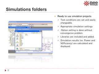
How to Estimate Design %Efficiency?
6
4. Add traces: AVG(W(LOAD)) for PO[W], -(AVG(W(+B))+AVG(W(-B))) for Supply power [W],
and -100*AVG(W(LOAD))/(AVG(W(+B))+AVG(W(-B))) for %Efficiency
Efficiency
93%
T=1/fin
Supply power
Output power: PO
%Efficiency
VO=15.85VIN](https://image.slidesharecdn.com/classdaudioamplifier-200410091049/85/Class-D-Audio-Amplifier-using-PSpice-6-320.jpg)


1. Ready-to-use simulation projects are provided with test conditions set, appropriate simulation settings, included libraries, and automatic calculation of results like power and efficiency. 2. The initial conditions for capacitors are set by running the simulation until startup, reading the startup voltages, and inputting them as the initial conditions for a second simulation with a smaller maximum time step. 3. Percent efficiency can be estimated by simulating the load power, supply power, and calculating the ratio between them over multiple output cycles.


![RF Module Design - [Chapter 6] Power Amplifier](https://cdn.slidesharecdn.com/ss_thumbnails/rfch6-150613070347-lva1-app6891-thumbnail.jpg?width=640&height=640&fit=bounds)


