Downloaded 23 times


![66
5.9.1 Estimation of Column Casting
In my site there are six types of column such as- C1, C2, C3, C3A, C4 and C5. The estimation of
the materials that used on those columns is given below:
Column Type- C3A
Number of column = 2
Column height = 8.33'
Column size = (10"×40") = (0.83'×3.33')
Volume of column = (0.83'×3.33'×8.33') = 23.02 cft
Total volume = (23.02×2) = 46.04 cft [no. of column= 2]
Dry volume = (46.04×1.5) = 69.03 cft
Mixing ratio = 1:1.5:3
Summation of the ratio = (1+1.5+3) = 5.5
Cement = (69.03/5.5) ×1 = 12.55 cft
= 10.05 bags [1.25 cft = 1 bag]
Sand = (69.03/5.5) ×1.5 = 18.84 cft
Stone Chips = (69.03/5.5) ×3 = 37.67 cft
Estimation of the casting materials for column is given in table:
Column
Types
Column
Size
Column
Length
(ft)
No of
Column
Volume
(cft)
Dry
Volume
(cft)
Cement
(bag)
Sand
(cft)
Stone
Chips
(cft)
C1 (12″x20″) 8.33' 2 30.48 45.72 6.65 12.47 24.94
C2 (12″x20″) 8.33' 4 60.64 91.44 16.62 24.94 49.88
C3 (12″x30″) 8.33' 2 41.65 62.48 9.09 17.04 34.08
C3A (10″x40″) 8.33' 2 46.05 69.07 10.05 18.84 37.67
C4 (12″x30″) 8.33' 2 41.65 62.48 9.09 17.04 34.08
C5 (15″x30″) 8.33' 2 52.06 78.09 11.35 21.29 42.59
Total= 62.85 117.62 235.24
Table 5.7: Estimation of the Casting Materials of Column](https://image.slidesharecdn.com/bakicompletedreport-190214050930/85/Civil-Engineering-Practicum-Report-83-320.jpg)
![67
But in the field total cement used = 60 bags [1 bag =1.25 cft]
= 75 cft
Dry volume = (75×5.5)/1 = 412.50 cft [mixing ratio =5.5]
Actual used of sand = (412.50/5.5) ×1.5 = 112.50 cft
Actual used of stone chips = (412.50/5.5) ×3 = 225 cft
Comparison of casting materials between estimation and actual used in the field is given below:
Materials Estimation Actual Used Difference (+/-)
Cement 62.85 bags 60 bags -2.85
Sand 117.62 cft 112.50 cft -5.12
Brick Chips 235.24 cft 225 cft -10.24
Table 5.8: Comparison of Casting Materials for Column
Figure 5.16: Comparison of Casting Materials for Column
Cement (bag) Sand (cft) Stone Chips (cft)
Estimated 62.85 117.62 235.24
Actual used 60 112.5 225
Difference 2.85 5.12 10.24
0
50
100
150
200
250
Comparison of Casting Materials](https://image.slidesharecdn.com/bakicompletedreport-190214050930/85/Civil-Engineering-Practicum-Report-84-320.jpg)


![102
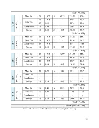
6.10.1 Estimation of Beam & Slab Casting
In my site the beam and slab were casted together. But here, I estimated beam and slab casting
individually. There are 10 types of beam and 7 types of panel (including lobby and varandah) are
there. The estimation of the materials that used on beams and slab are given below:
Panel- 1
Number of panel = 2
Panel thickness = 5" = 0.43'
Panel size = (18.75ʹ×13.5ʹ)
Panel volume = (18.75ʹ×13.5ʹ×0.43) = 108.84 cft
Total casting = (108.84×2) = 217.68 cft [no. of panel= 2]
Dry volume = (217.68×1.5) = 326.53 cft
Mixing ratio = 1:2:4
Summation of the ratio = (1+2+4) = 7
Cement = (326.53/7) ×1 = 46.65 cft
= 37.32 bags [1.25 cft = 1 bag]
Sand = (326.53/7) ×2 = 93.29 cft
Brick Chips = (326.53/7) ×4 = 186.58 cft
Estimation of the casting materials for slab is given in table:
Panel
Name Panel Size
Panel
Thickness
(in)
Panel
No
Volume
(cft)
Dry
Volume
(cft)
Cement
(bag)
Sand
(cft)
Brick
Chips
(cft)
Panel-1 (18.75ʹ×13.5ʹ) 5″ 2 217.68 326.53 37.32 93.29 186.58
Panel-2 (19.5ʹ×9.17ʹ) 5″ 2 153.78 230.67 26.36 65.91 131.81
Panel-3 (19.5ʹ×18.58ʹ) 5.5″ 1 166.66 249.99 28.57 71.43 142.85
Panel-4 (14.25ʹ×9.17ʹ) 5″ 2 112.37 168.56 19.26 48.16 96.32
Panel-5 (18.58ʹ×14.25ʹ) 5″ 1 113.84 170.76 19.52 48.79 97.57
Lobby (10ʹ×4.33ʹ) 5″ 1 18.62 27.93 3.19 7.98 15.96
Varanda (2.83ʹ×37.33ʹ) 6″ 1 52.82 79.23 9.05 22.64 45.27
Total= 143.27 358.2 716.36
Table 6.15: Estimation of the Casting Materials of Slab](https://image.slidesharecdn.com/bakicompletedreport-190214050930/85/Civil-Engineering-Practicum-Report-119-320.jpg)
![103
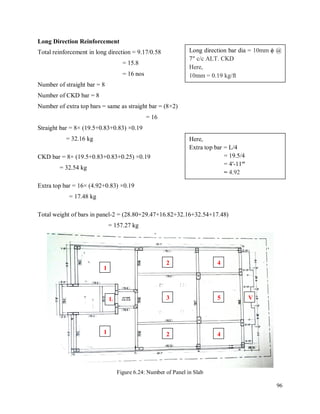
Beam Type- FB1
Number of beam = 2
Beam length = 55.58'
Beam size = (10"×21") = (0.58'×1.75')
Volume of column = (0.58'×1.75'×55.58') = 56.41 cft
Total casting = (56.41×2) = 112.82 cft [no. of beam= 2]
Dry volume = (112.82×1.5) = 169.23 cft
Mixing ratio = 1:2:4
Summation of the ratio = (1+2+4) = 7
Cement = (169.23/7) ×1 = 24.18 cft
= 19.34 bags [1.25 cft = 1 bag]
Sand = (169.23/7) ×2 = 48.35 cft
Brick Chips = (169.23/7) ×4 = 96.70 cft
Estimation of the casting materials for beam is given in table:
Beam
Types Beam Size
Beam
Length
(ft)
No of
Beam
Volume
(cft)
Dry
Volume
(cft)
Cement
(bag)
Sand
(cft)
Brick
Chips
(cft)
FB-1 (10″x21″) 55.58ʹ 2 112.82 169.23 19.34 48.35 96.70
FB-2 (10″x21″) 36.25ʹ 2 105.13 157.69 18.02 45.05 90.09
FB-3 (10″x21″) 18.33ʹ 2 53.16 79.74 9.11 22.78 45.56
FB-4 (10″x21″) 18.67ʹ 1 27.07 40.61 4.64 11.60 23.21
FB-5 (10″x21″) 15.17ʹ 2 43.99 65.98 7.54 18.85 37.70
FB-6A (10″x21″) 40.25ʹ 1 58.36 87.54 10 25.01 50.02
FB-7 (10″x24″) 40.25ʹ 1 66.82 100.22 11.45 28.63 57.27
FB-8 (10″x21″) 40.25ʹ 1 58.36 87.54 10 25.01 50.02
FB-9 (10″x21″) 7.17ʹ 2 20.79 31.19 3.56 8.91 17.82
FB-10 (10″x18″) 11.67ʹ 1 14.59 21.88 2.50 6.25 12.50
Total= 96.16 240.4 480.80
Table 6.16: Estimation of the Casting Materials of Beam](https://image.slidesharecdn.com/bakicompletedreport-190214050930/85/Civil-Engineering-Practicum-Report-120-320.jpg)
![104
As I said earlier, the beam and slab was casted together in my site. So the summation of the
casting materials of beam and slab are:
The total cement estimation = (96.16+143.27) = 239.43 bags
The total sand estimation = (240.40+358.20) = 598.60 cft
The total brick chips estimation = (480.80+716.36) = 1197.16 cft
But in the field total cement used = 226 bags = 282.50 cft [1 bag =1.25 cft]
Dry volume = (282.50×7)/1 = 1977.50 cft [mixing ratio =7]
Actual used of sand = (1977.50/7) ×2 = 565 cft
Actual used of brick chips = (1977.50/7) ×4 = 1130 cft
Comparison between estimation and actual use of casting materials in the field is given below:
Materials Estimation Actual Used Difference (+/-)
Cement 239.43 bags 226 bags -13.43
Sand 598.60 cft 565 cft -33.60
Brick Chips 1197.16 cft 1130 cft -67.16
Table 6.17: Comparison of Casting Materials for Beam & Slab
Figure 6.32: Comparison of Casting Materials for Beam & Slab
Cement (bag) Sand (cft) Brick Chips (cft)
Estimated 239.43 598.6 1197.16
Actual used 226 565 1130
Difference 13.43 33.6 67.16
0
200
400
600
800
1000
1200
1400
Comparison of Casting Materials](https://image.slidesharecdn.com/bakicompletedreport-190214050930/85/Civil-Engineering-Practicum-Report-121-320.jpg)


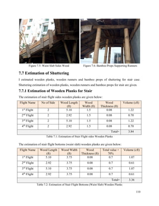


![116
7.10.1 Estimation of Stair Casting
The estimation of the materials that used on stair casting is given below:
Landing
Number of landing = 4
Landing thickness = 6" = 0.5'
Landing area = (3.75ʹ×3.75ʹ)
Landing volume = (3.75ʹ×3.75ʹ×0.5') = 7.03 cft
Total volume = (7.03×4) = 28.12 cft [no. of landing= 4]
Dry volume = (28.12×1.5) = 42.18 cft
Mixing ratio = 1:2:4
Summation of the ratio = (1+2+4) = 7
Cement = (42.18/7) ×1 = 6.03 cft
= 4.82 bags [1.25 cft = 1 bag]
Sand = (42.18/7) ×2 = 12.05 cft
Brick Chips = (42.18/7) ×4 = 24.10 cft
Waist Slab
Number of waist slab = 2
Waist slab thickness = 6" = 0.5'
Waist slab area = (3.75ʹ×5.10ʹ) [1st
and 3rd
waist slab]
Waist slab volume = (3.75ʹ×5.10ʹ×0.5') = 9.56 cft
Total volume = (9.56×2) = 19.13 cft [no. of waist slab= 2]
Dry volume = (19.13×1.5) = 28.69 cft
Mixing ratio = 1:2:4
Summation of the ratio = (1+2+4) = 7
Cement = (28.69/7) ×1 = 4.09 cft
= 3.28 bags [1.25 cft = 1 bag]
Sand = (28.69/7) ×2 = 8.19 cft
Brick Chips = (28.69/7) ×4 = 16.39 cft](https://image.slidesharecdn.com/bakicompletedreport-190214050930/85/Civil-Engineering-Practicum-Report-133-320.jpg)
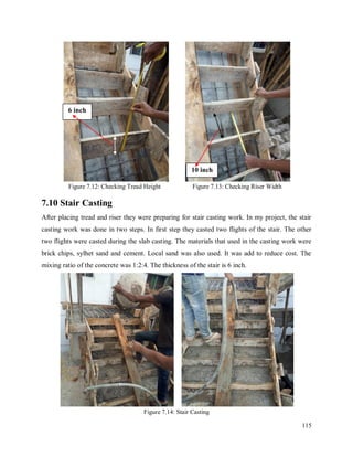
![117
Steps
Number of steps = 16
Step length = 3.75ʹ
Tread length = 6" = 0.5ʹ
Riser height = 10" = 0.83ʹ
Step area = (1/2×0.5ʹ×0.83ʹ)
Step volume = (1/2×0.5ʹ×0.83'×3.75ʹ) = 0.78 cft
Total volume = (0.78×16) = 12.45 cft [no. of step= 16]
Dry volume = (12.45×1.5) = 18.68 cft
Mixing ratio = 1:2:4
Summation of the ratio = (1+2+4) = 7
Cement = (18.68/7) ×1 = 2.67 cft
= 2.14 bags [1.25 cft = 1 bag]
Sand = (18.68/7) ×2 = 5.34 cft
Brick Chips = (18.68/7) ×4 = 10.68 cft
Estimation of the casting materials for stair is given in table:
Flight
Types
NOS Area (sft) Thickness
(in)
Volume
(cft)
Dry
Volume
(cft)
Cement
(bag)
Sand
(cft)
Brick
Chips
(cft)
Landing 4 3.75ʹ×3.75ʹ 6" 28.12 42.18 4.82 12.05 24.10
Waist Slab
(1st
& 3rd
)
2 3.75ʹ×5.10ʹ 6" 19.13 28.69 3.80 8.19 16.39
Waist Slab
(2nd
& 4th
)
2 3.75ʹ×2.92ʹ 6" 10.95 16.43 1.88 4.69 9.39
Steps 16 1/2×0.5ʹ×0.83ʹ - 12.45 18.68 2.14 5.34 10.68
Total= 12.64 30.27 60.56
Table 7.8: Estimation of the Casting Materials of Stair](https://image.slidesharecdn.com/bakicompletedreport-190214050930/85/Civil-Engineering-Practicum-Report-134-320.jpg)
![118
But in the field total cement used = 11 bags [1 bag = 1.25 cft]
= 13.75 cft
Dry volume = (13.75×7)/1 = 96.25 cft [mixing ratio = 7]
Actual used of sand = (96.25/7) ×2 = 27.50 cft
Actual used of brick chips = (96.25/7) ×4 = 55 cft
Comparison of casting materials between estimation and actual used in the field is given below:
Materials Estimation Actual Used Difference (+/-)
Cement 12.64 bags 11 bags -1.64
Sand 30.27 cft 27.50 cft -2.77
Brick Chips 60.56 cft 55 cft -5.56
Table 7.9: Comparison of Casting Materials for Stair
Figure 7.15: Comparison of Casting Materials for Stair
Cement (bag) Sand (cft) Stone Chips (cft)
Estimated 12.64 30.27 60.56
Actual used 11 27.5 55
Difference 1.64 2.77 5.56
0
10
20
30
40
50
60
70
Comparison of Casting Materials](https://image.slidesharecdn.com/bakicompletedreport-190214050930/85/Civil-Engineering-Practicum-Report-135-320.jpg)


This document appears to be a student's practicum report on studying the super structural construction process of a ten-story residential building. It includes sections on the company profile, project details and design specifications, construction materials and equipment used, and descriptions of the construction processes for columns, beams, slabs and stairs. The report is submitted to fulfill degree requirements and acknowledges assistance from supervisors and others involved in the project.