The document discusses various topics related to processes, operating systems, and real-time embedded systems design including:
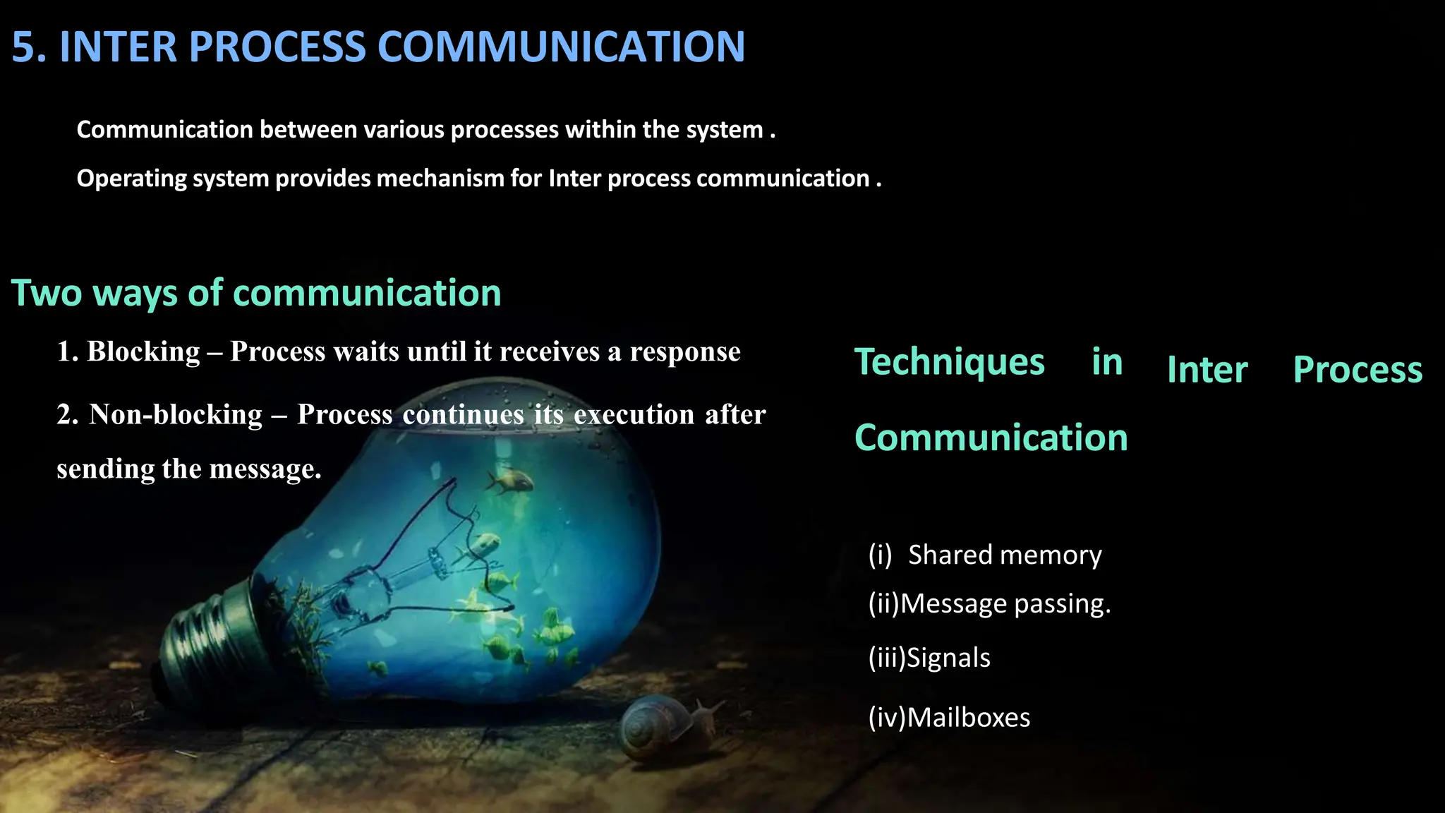
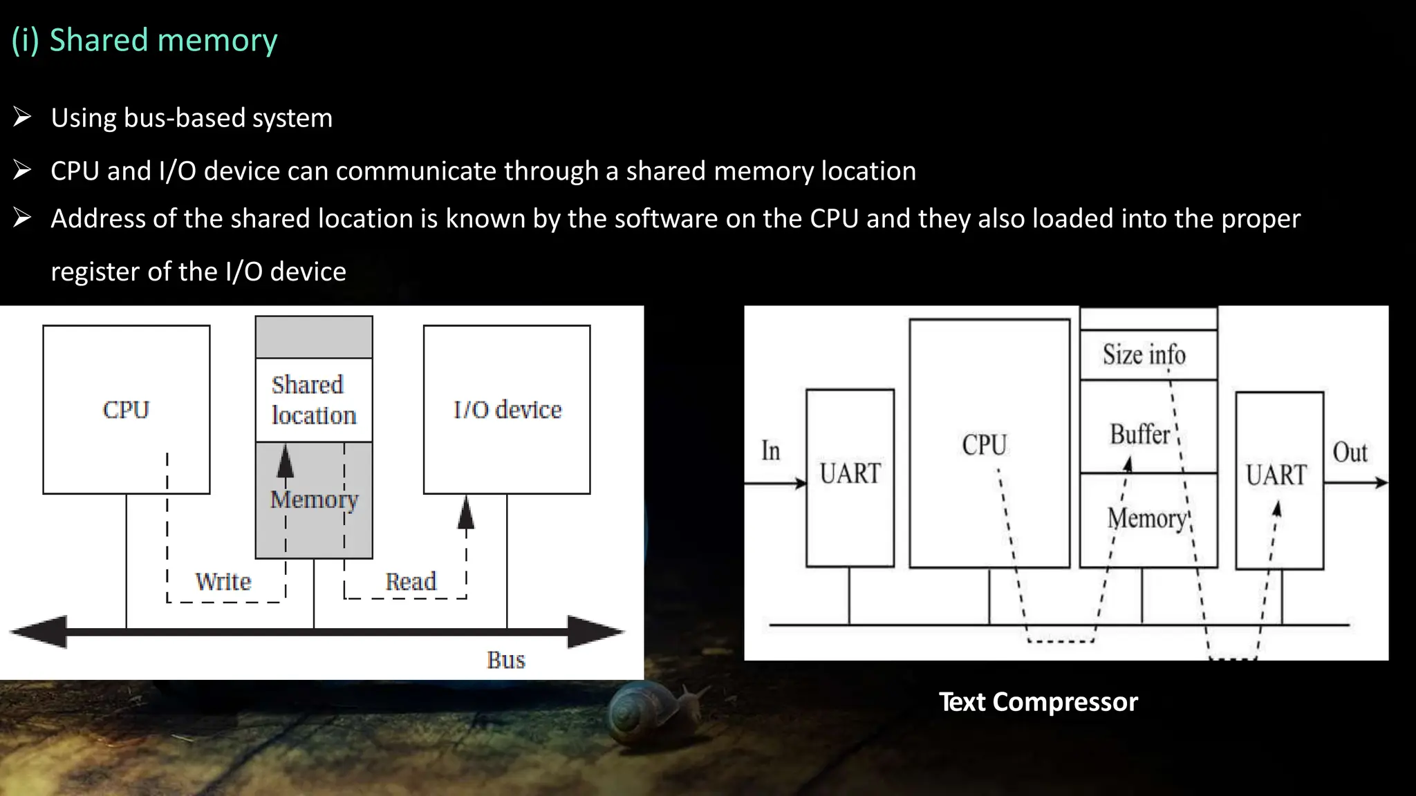
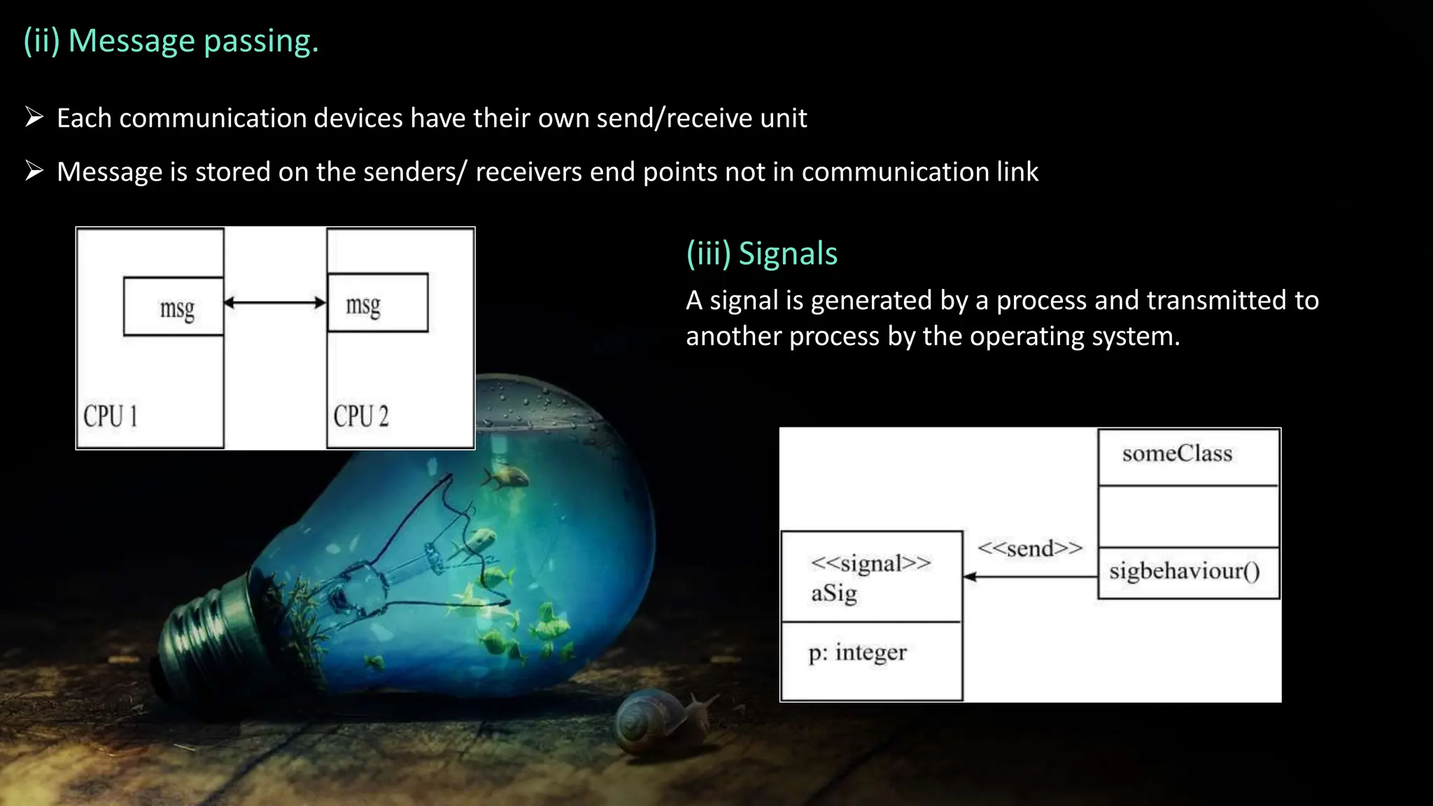
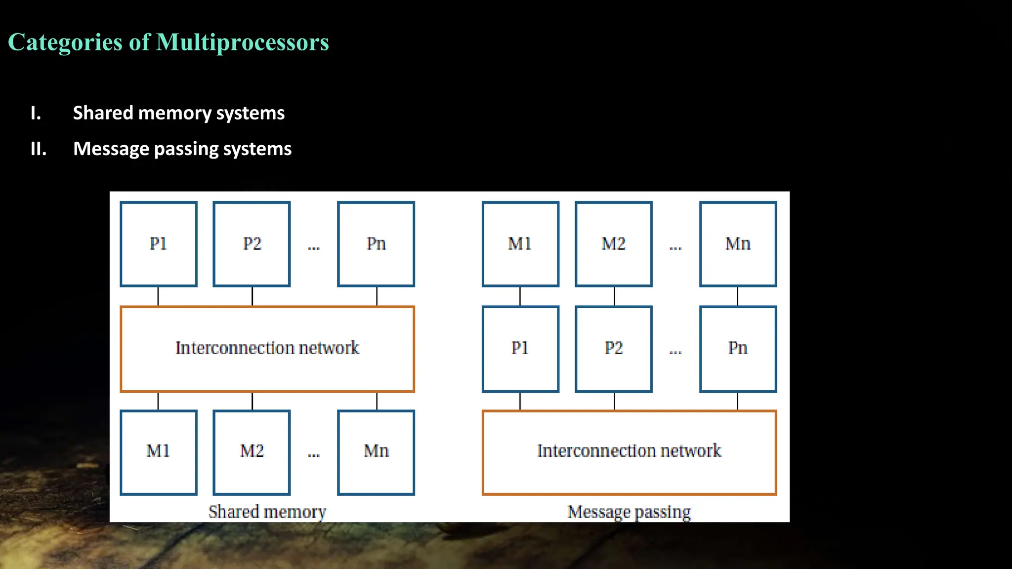
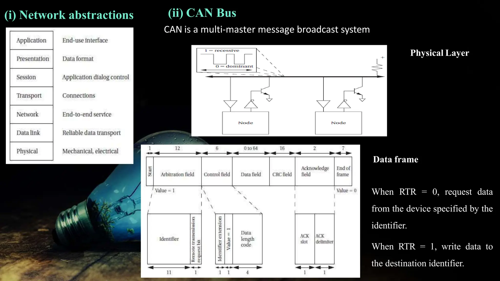
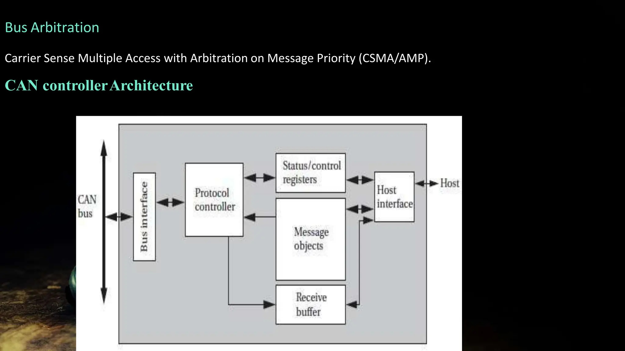
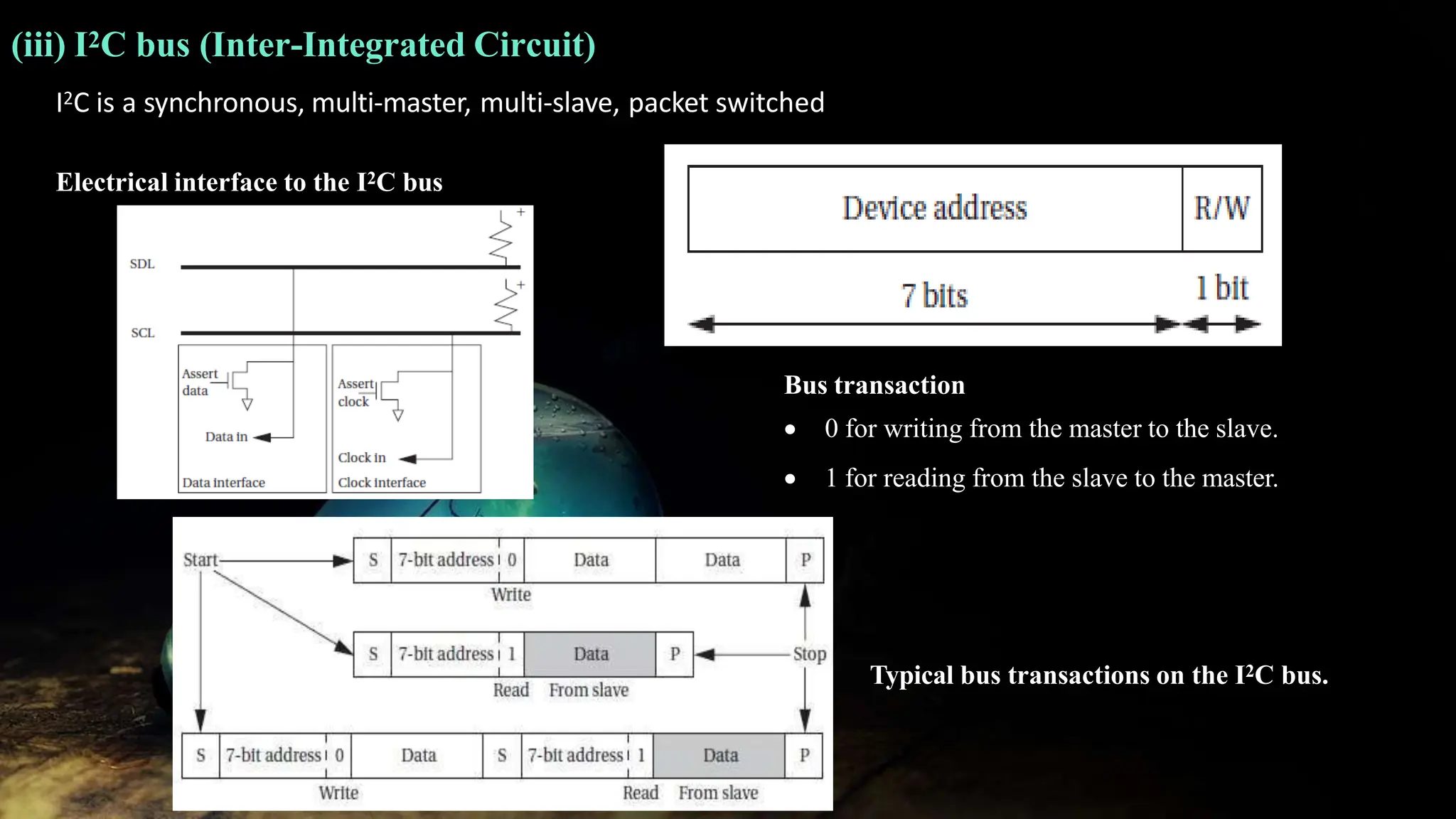
1. Interprocess communication mechanisms like shared memory, message passing, signals, and mailboxes.
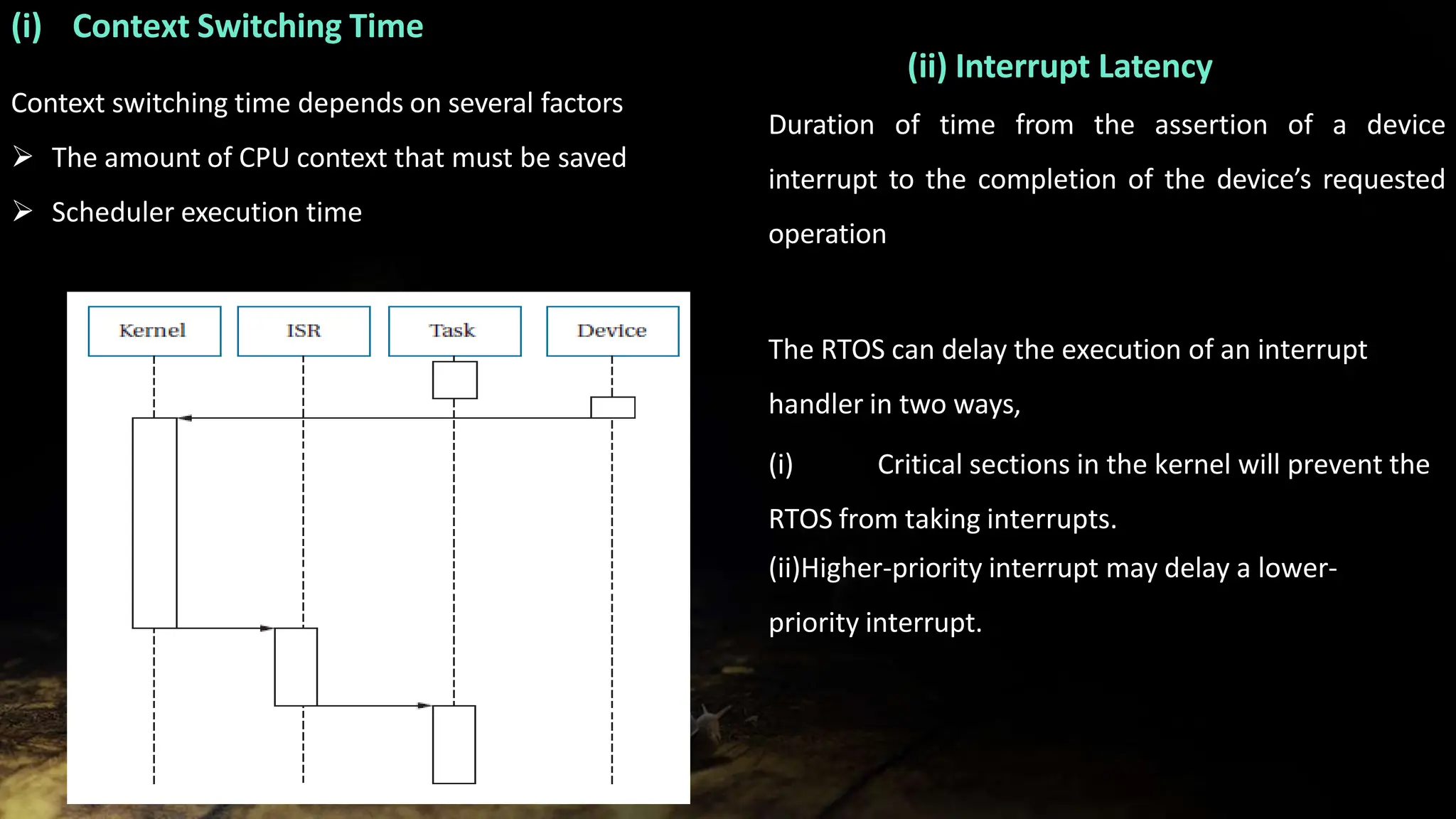
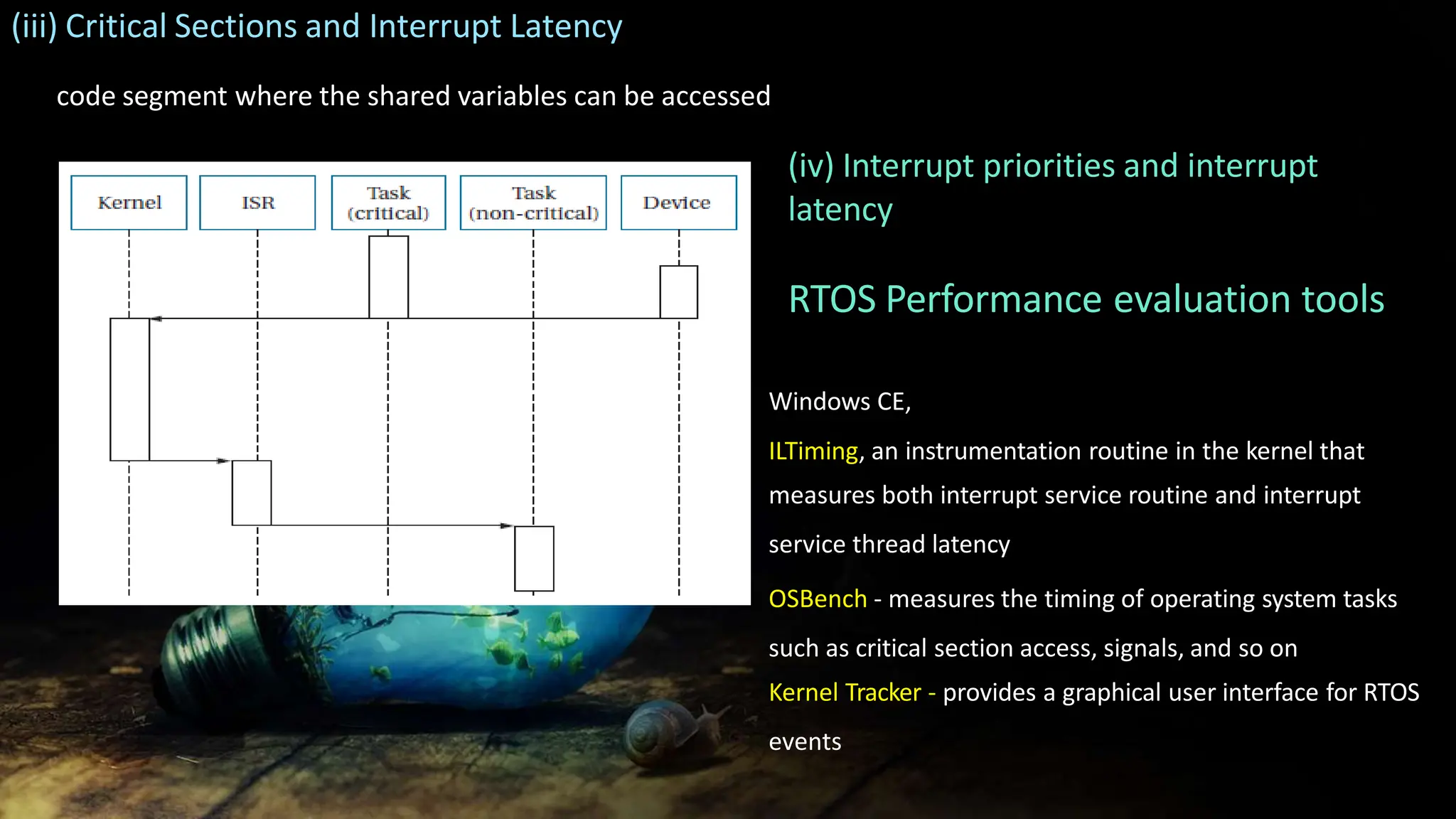
2. Factors that affect operating system performance such as context switching time and interrupt latency.
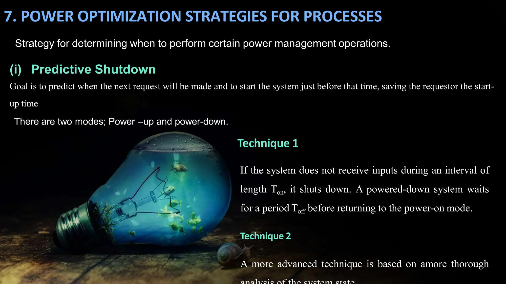
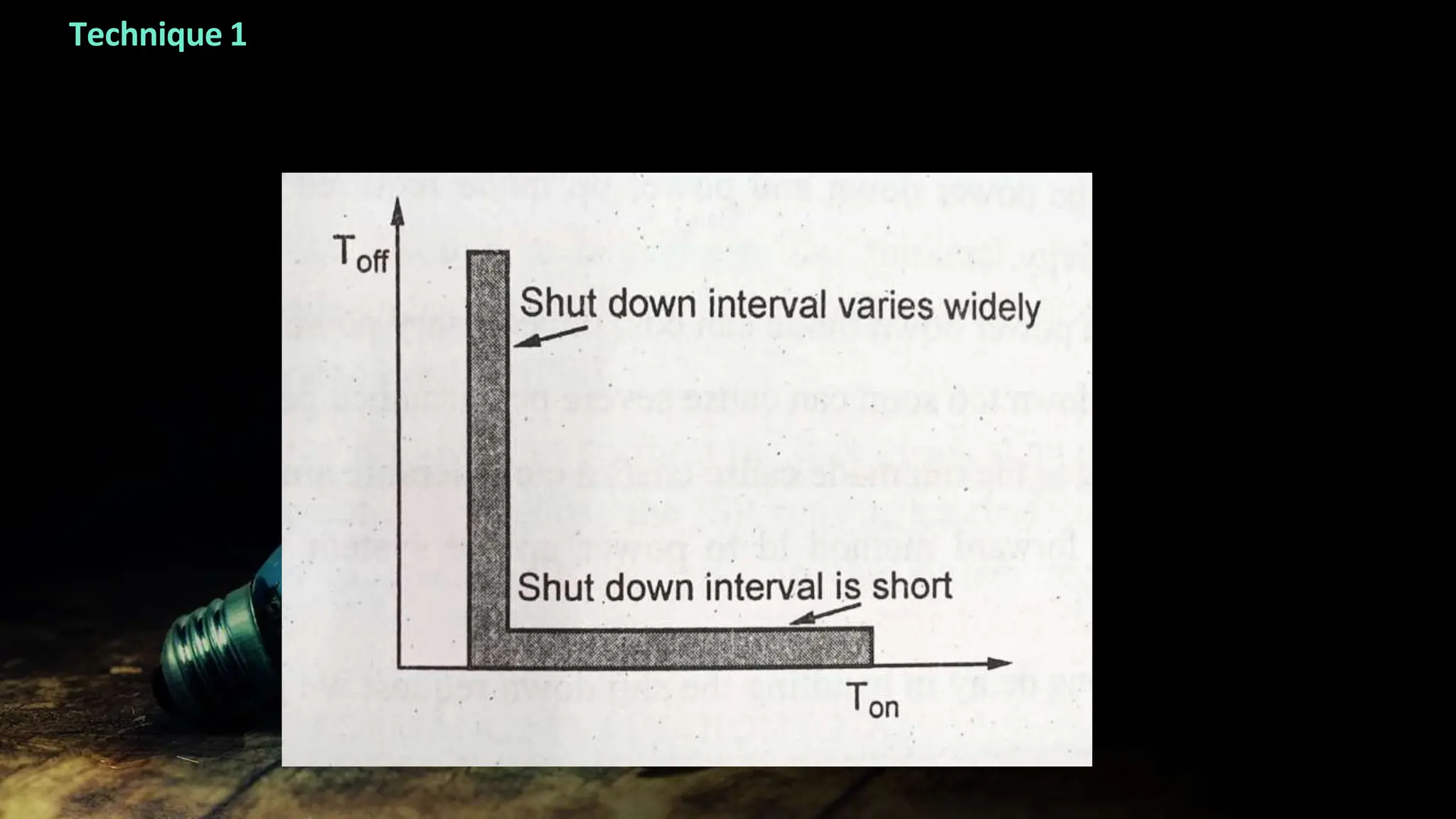
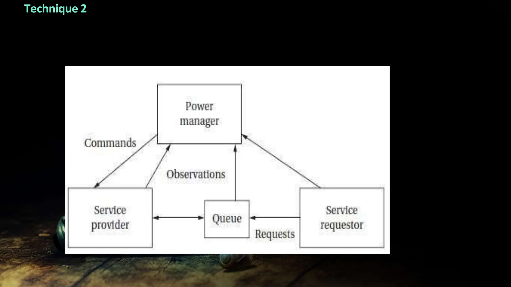
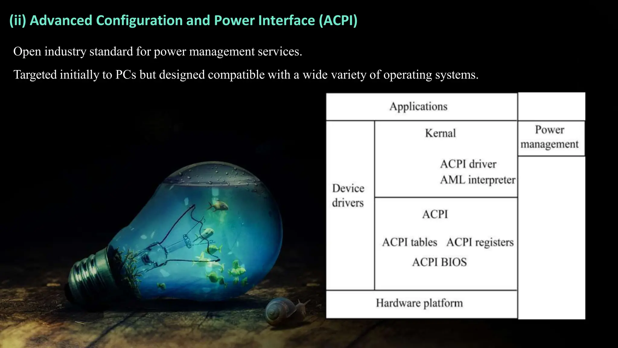
3. Power optimization strategies for processes including predictive shutdown and the Advanced Configuration and Power Interface standard.
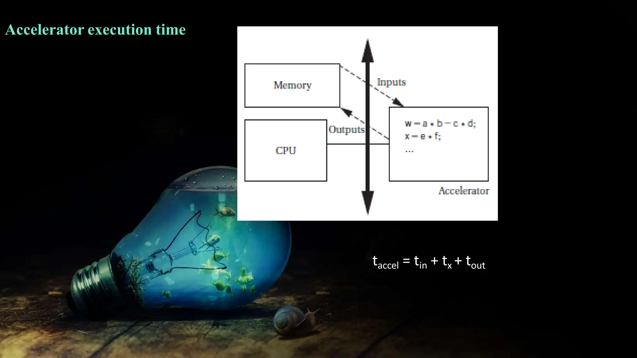
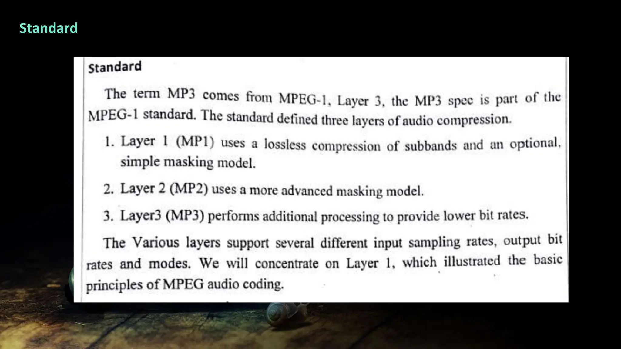
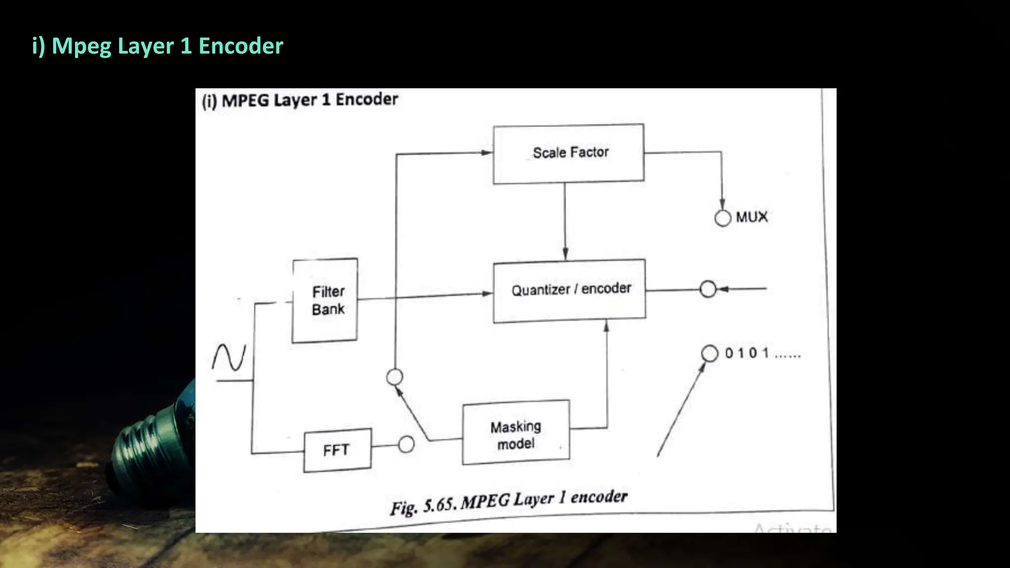
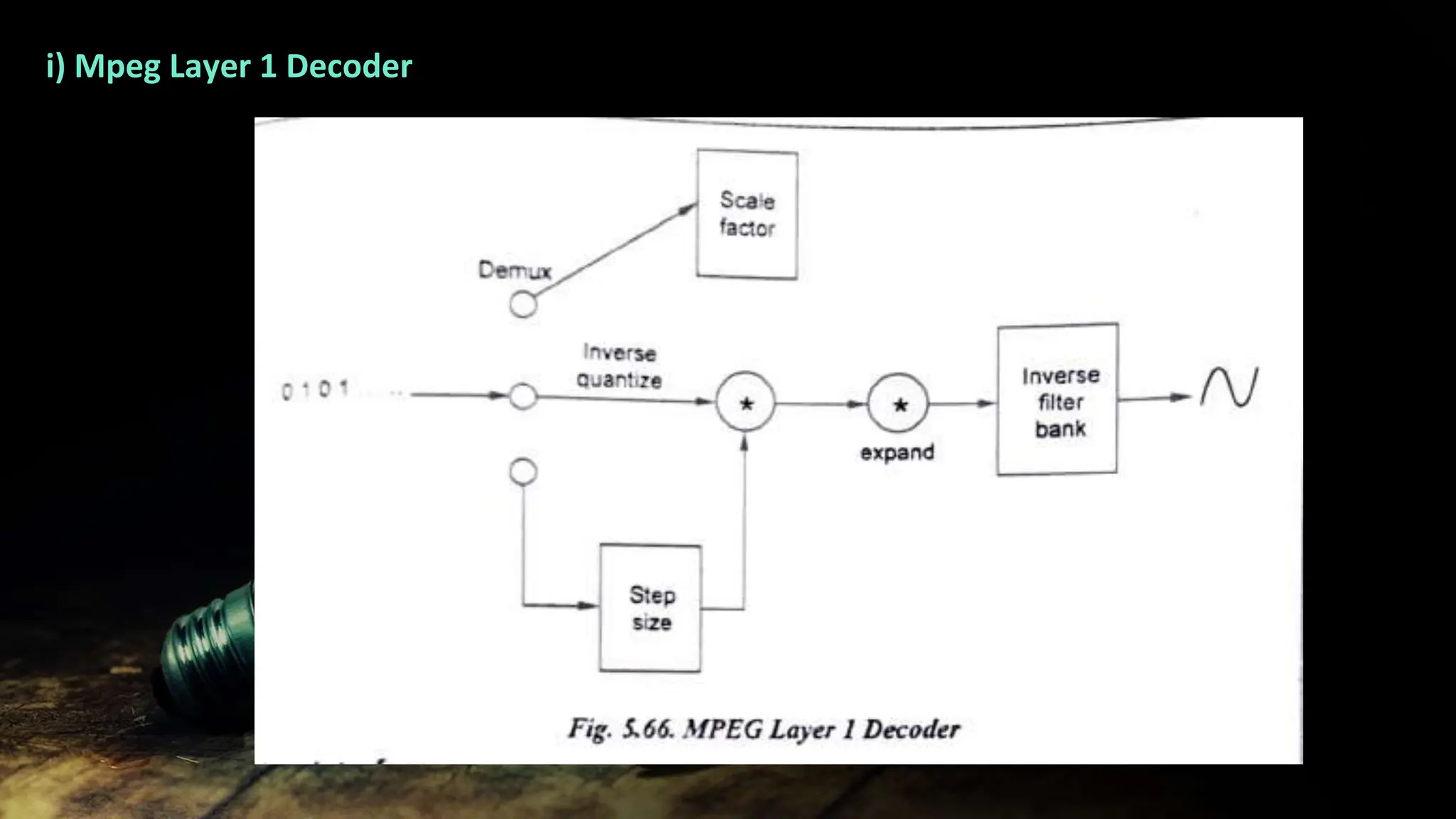
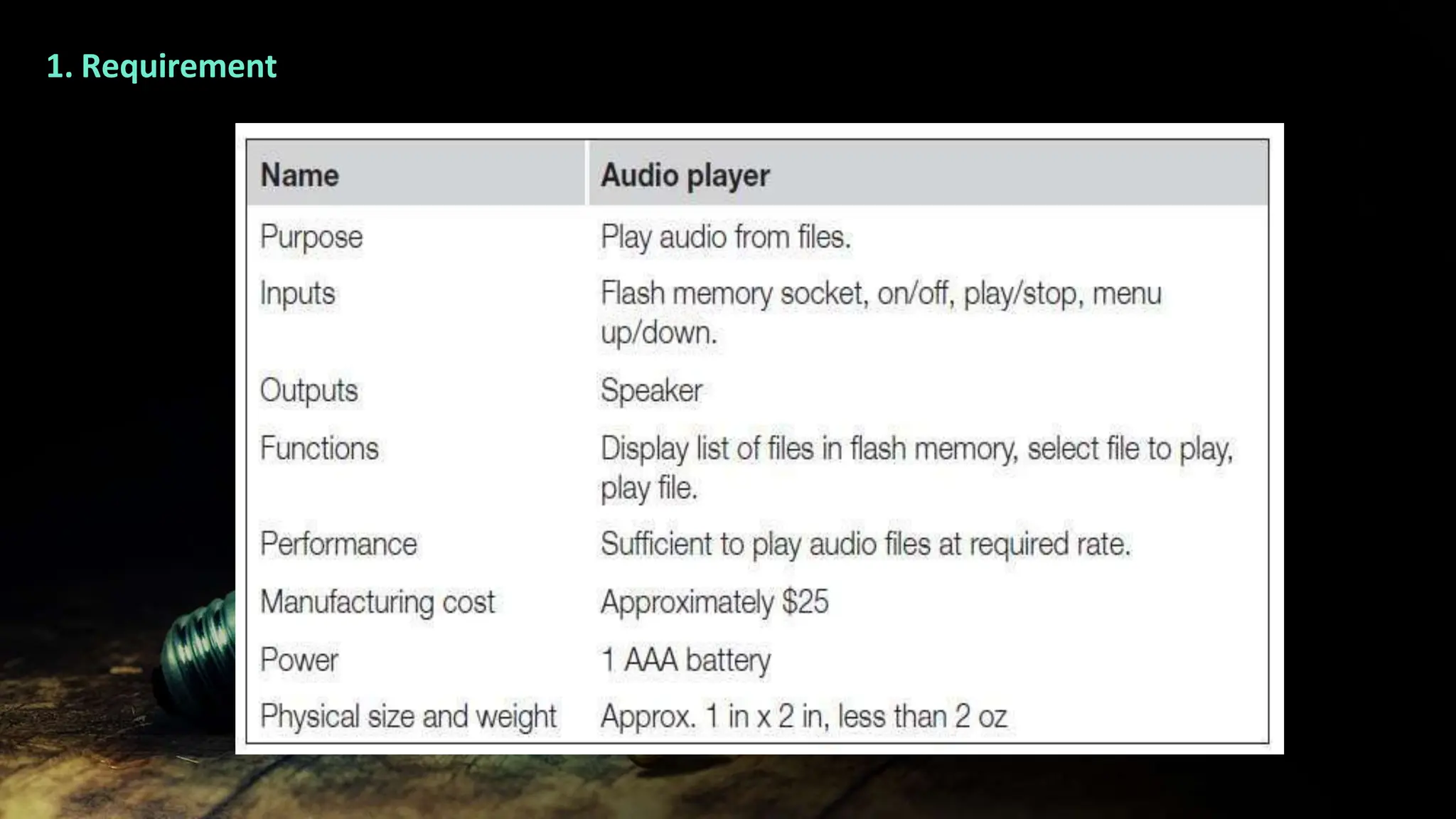
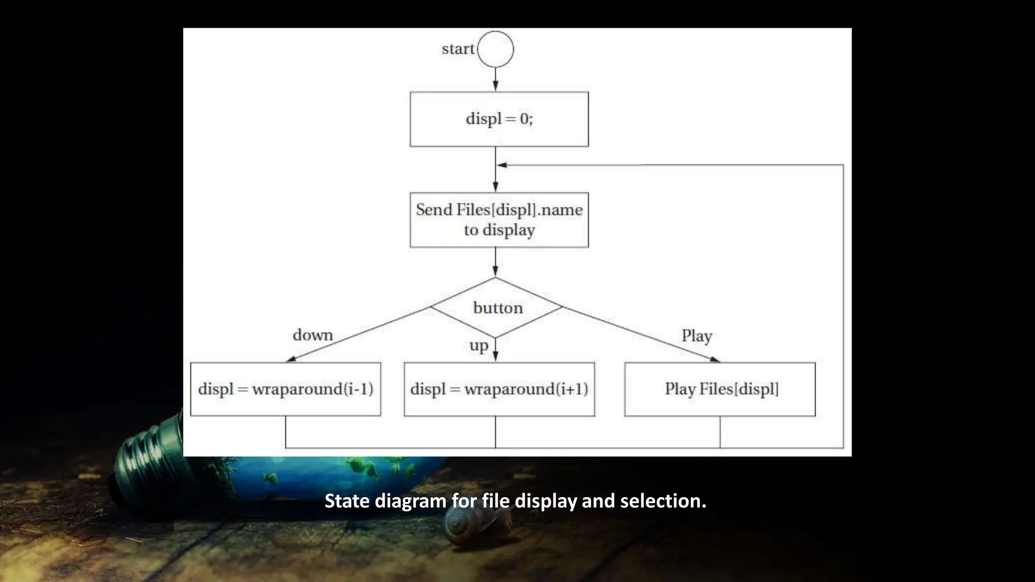
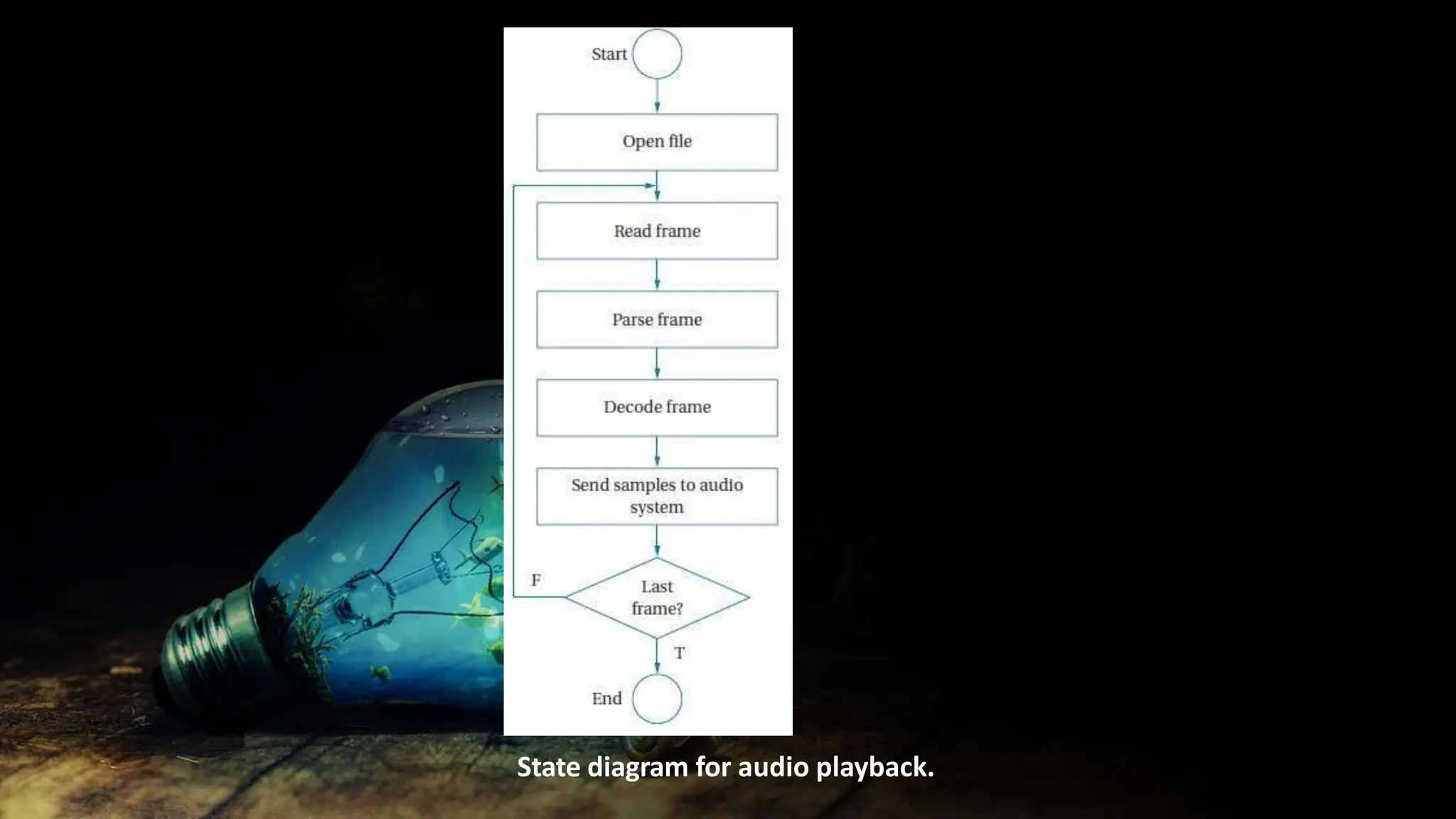
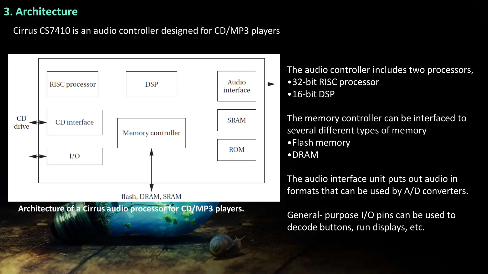
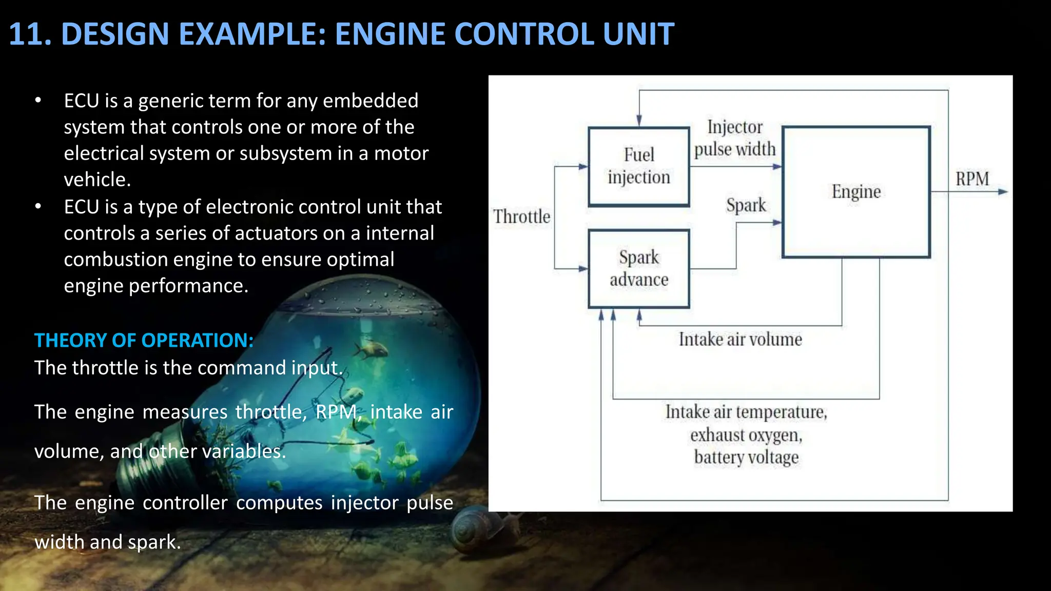
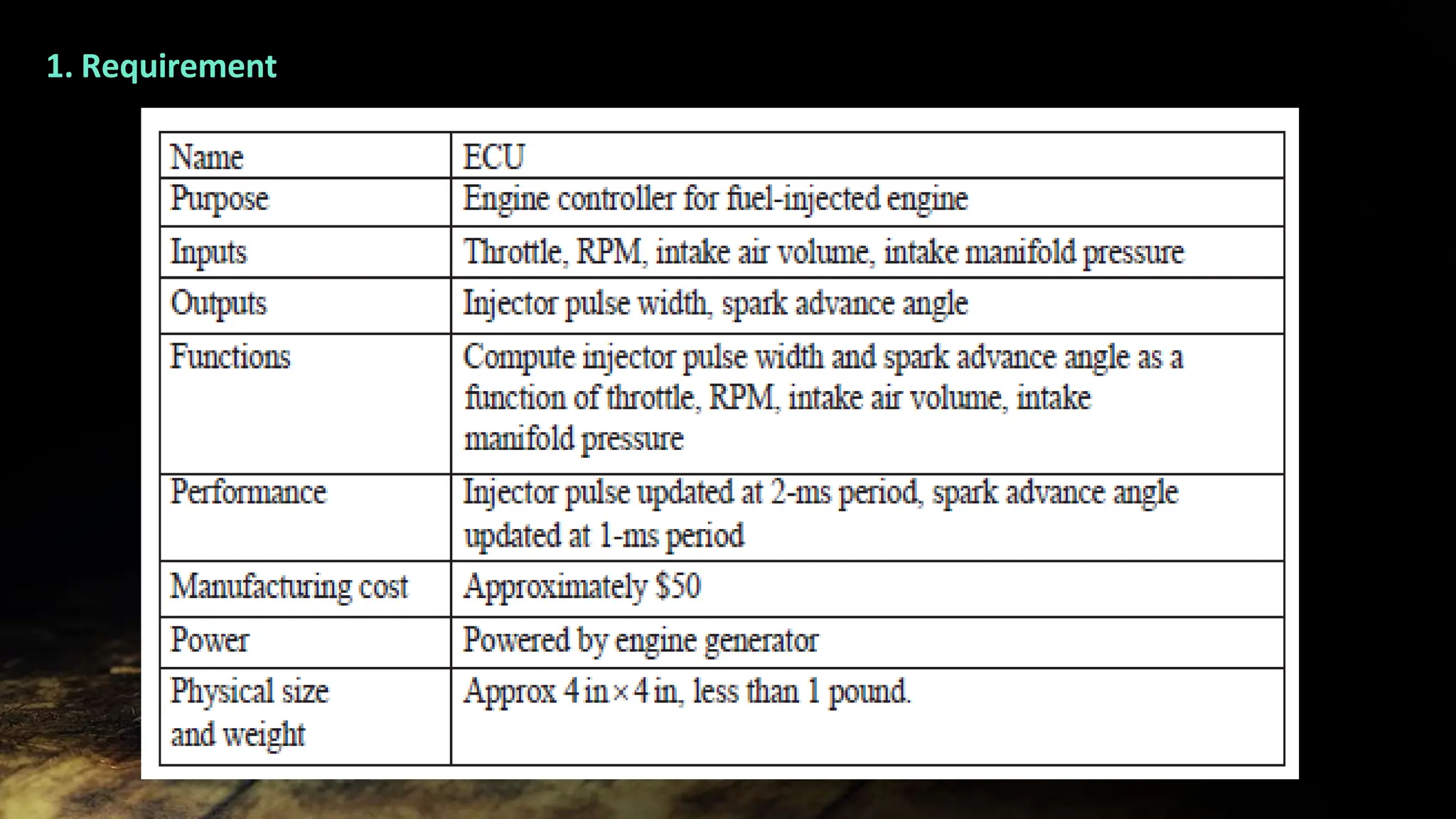
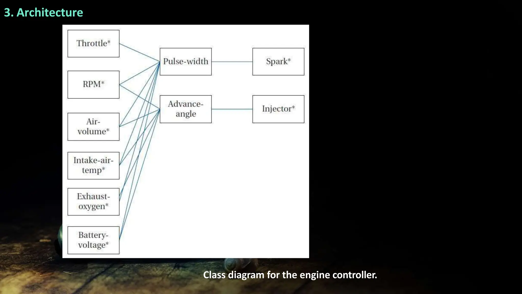
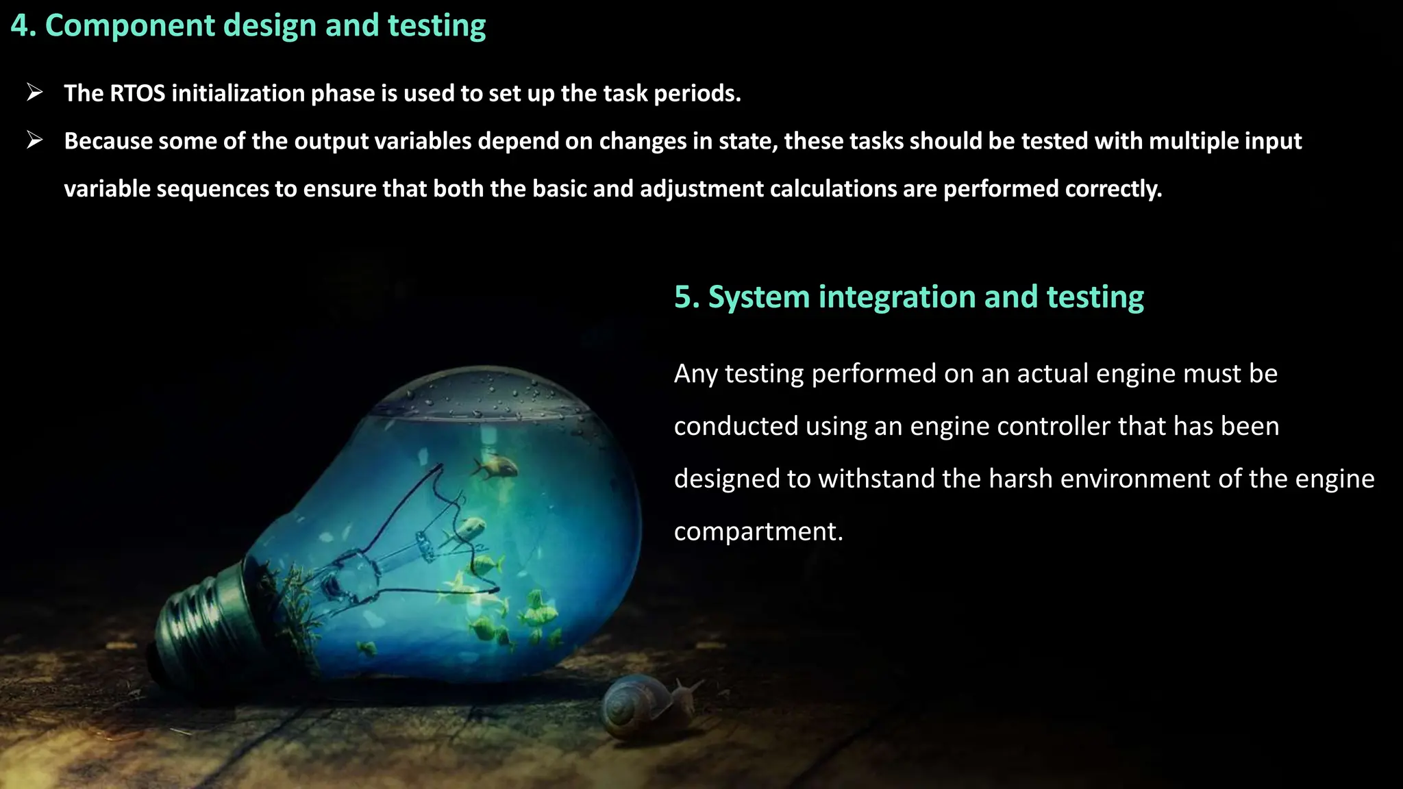
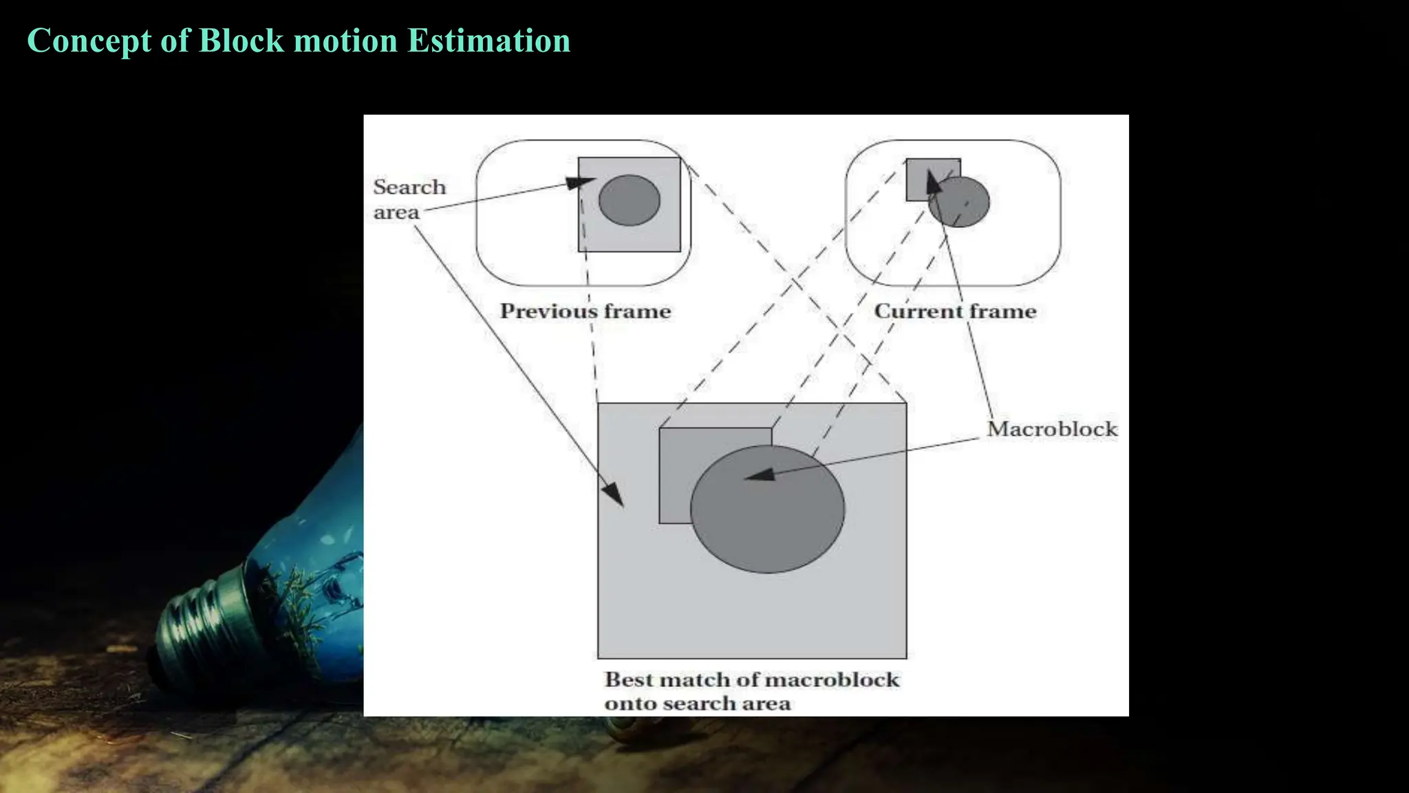
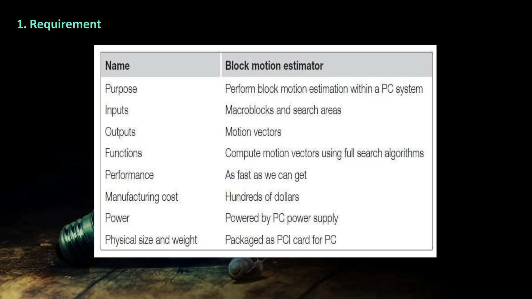
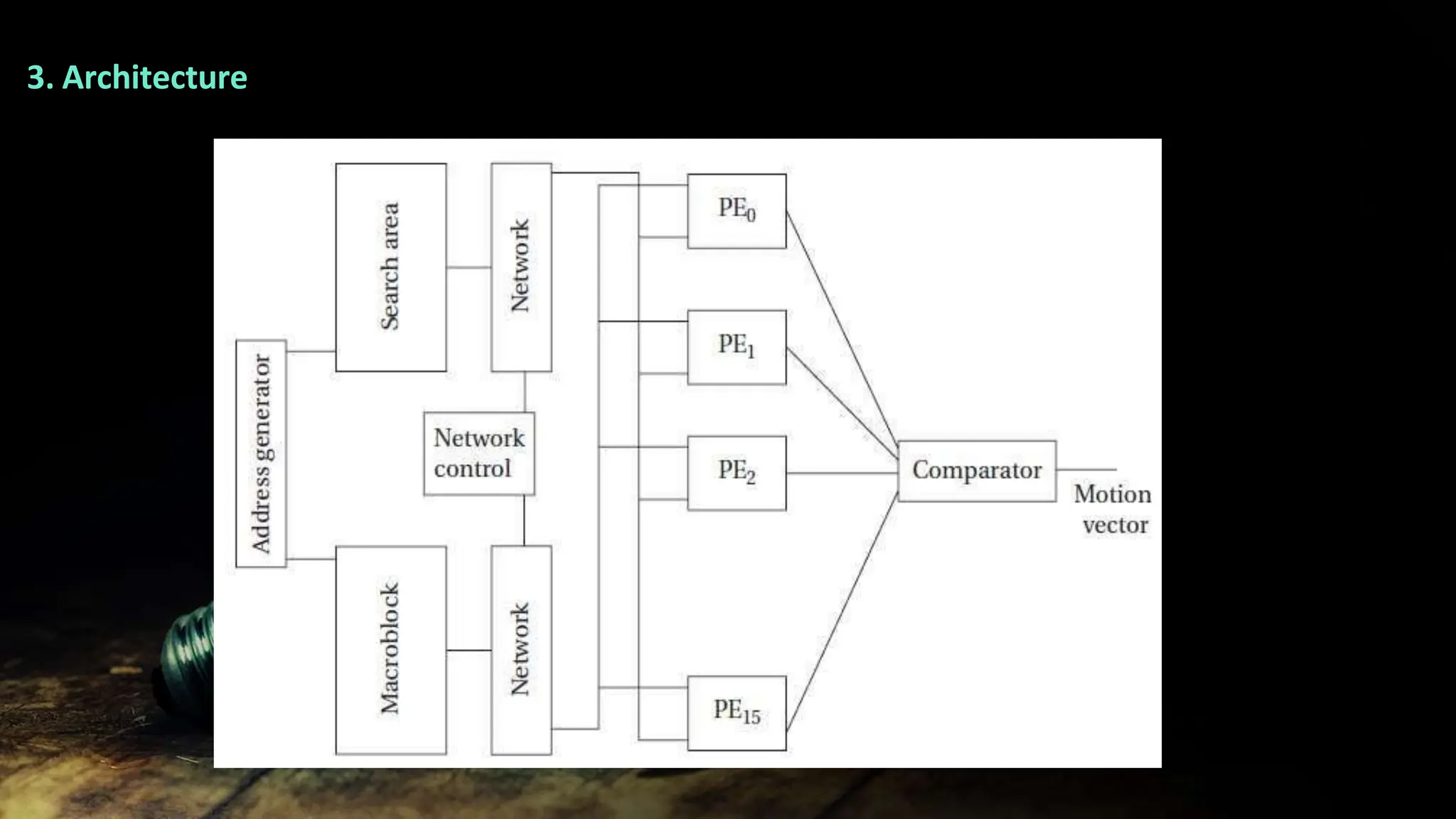
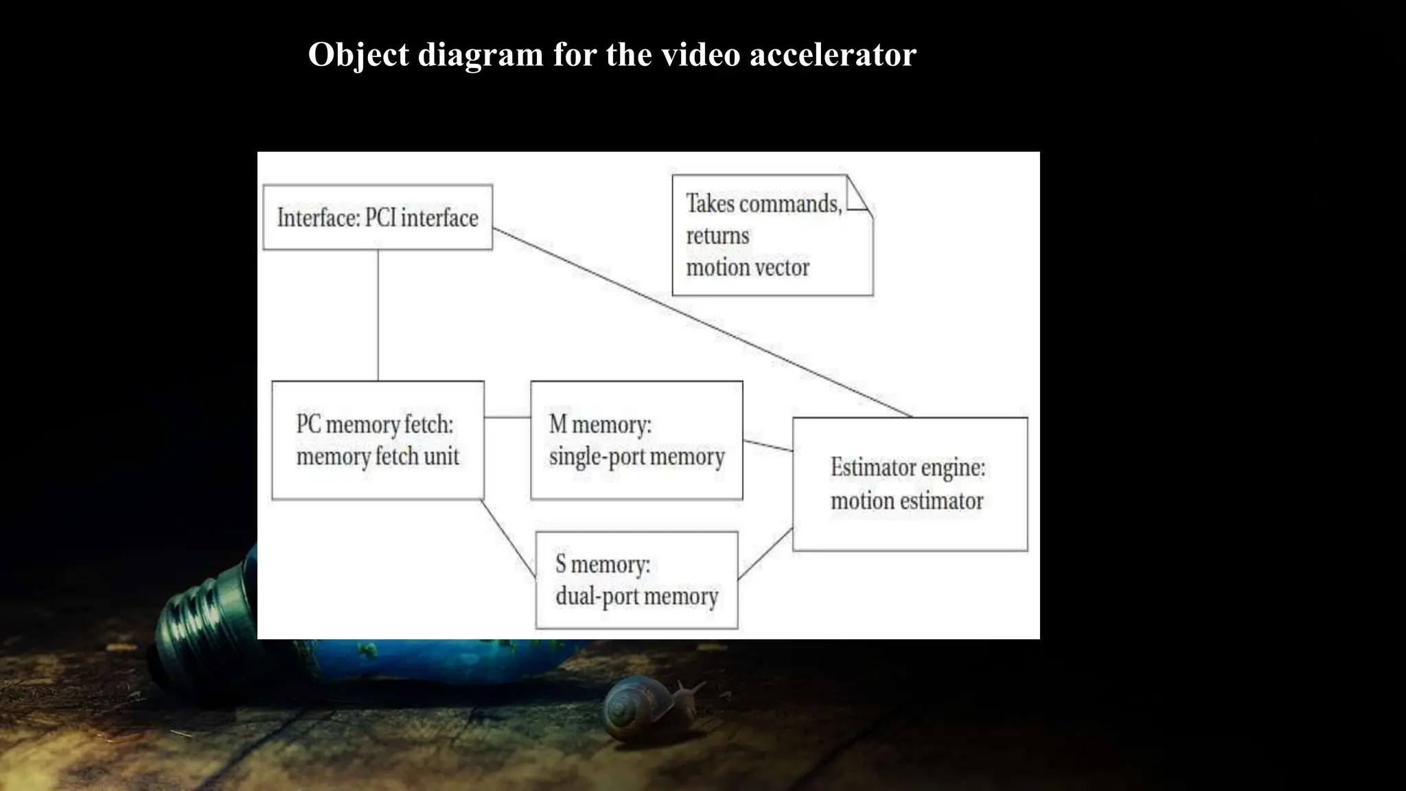
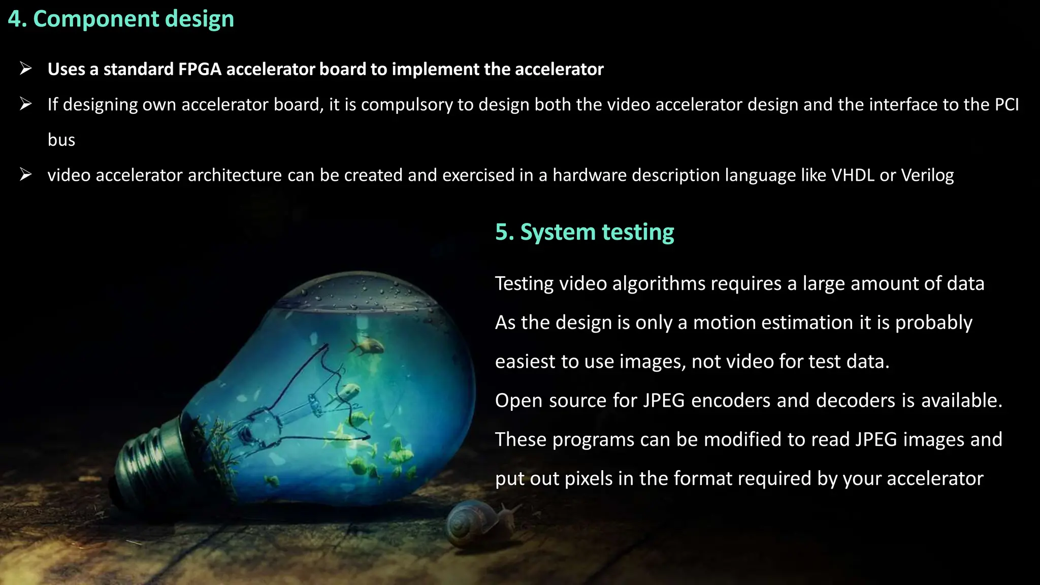
4. Examples of real-time embedded system designs including an audio player, engine control unit, and video accelerator.


![3. POSIX Pipes
(i) pipe ( ) function
A parent process uses the
pipe ( ) function to create a
pipe to talk to a child.
It must do so before the
child itself is created.
if (pipe(pipe_ends) < 0) { /* create the pipe, check for errors */
perror(“pipe”);
break;
}
/* create the process */
childid = fork();
if (childid == 0) { /* the child reads from pipe_ends[1]*/
childargs[0] = pipe_ends[1];
/* pass the read end descriptor to the new incarnation of child */
execv(“mychild”,childargs);
perror(“execv”);
exit(1);
}
else { /* the parent writes to pipe_ends[0] */
}](https://image.slidesharecdn.com/ec8791-u5-ppt-231010035726-4c7e801d/75/EC8791-U5-PPT-pptx-56-2048.jpg)