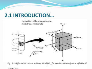
SlideShare a Scribd company logo
1 of 125
2.1 INTRODUCTION
The heat flux given in equation (1.4)
(1.4)
can be written in a more general (three
dimensional) form as
(2.1)
or
(2.2)
dx
dT
k
A
Q
q 


.





















z
T
k
y
T
j
x
T
i
k
T
k
q
 
z
y
x kq
jq
iq
q 



2.1 INTRODUCTION…
Comparison of one dimensional and three dimensional heat flow
2.1 INTRODUCTION…
Major objectives in a conduction analysis is
 to determine the temperature field,
 to determine the conduction heat flux,
 for a solid, to ascertain structural integrity through
 determination of thermal stresses,
 expansions, and
 deflections.
 to optimize the thickness of an insulating material.
2.1 INTRODUCTION…
Fig. 2.1 Differential control volume, dx.dy.dz, for conduction analysis in Cartesian
coordinates
Derivation of heat equation in
rectangular coordinate
2.1 INTRODUCTION…
The conservation of energy principle is used to find the
conduction (energy diffusion) equation.
Referring to Fig. 2.1,
dxdydz
t
T
ρc
volume
control
the
in
stored
energy
of
rate
E
dxdydz
q
volume
control
the
in
generated
energy
of
rate
E
volume
control
the
leaving
energy
of
rate
E
volume
control
the
to
entering
energy
of
rate
E
p
st
.
.
gen
.
out
.
in
.








2.1 INTRODUCTION…
Applying the energy balance equation to the control volume,
(2.3)
(2.4)
But from Taylor series approximation,
(2.5)
And from Fourier’s law
(2.6)
st
out
gen
in E
E
E
E
.
.
.
.



dxdydz
t
T
c
dxdy
q
dxdz
q
dydz
q
dxdydz
q
dxdy
q
dxdz
q
dydz
q
p
dz
z
dy
y
dx
x
z
y
x












 
)
(
)
(
.
z
q
q
q
dy
y
q
q
q
dx
x
q
q
q z
z
dz
z
y
y
dy
y
x
x
dx
x











 

 ,
,
z
T
k
q
y
T
k
q
x
T
k
q z
y
x











 ,
,
2.1 INTRODUCTION…
Substituting equations (2.5) and (2.6) in to equation
(2.4) and dividing by dxdydz gives
(2.7)
Where = energy generated per unit volume ( )
ρ = density ( )
=specific heat capacity (J/kg.K)
Equation (2.7) is a general transient three dimensional
diffusion equation in rectangular coordinate system
with energy generation.
t
T
c
z
T
k
z
y
T
k
y
x
T
k
x
q p





































 
.
.
q
p
c
3
/ m
kg
3
/ m
W
2.1 INTRODUCTION…
For materials with constant thermal conductivity k,
equation (2.7) can be written as
is called thermal diffusivity (m2/s ). It is clear
from the above equation that the ability of a material
to let heat pass through it increases with increasing
thermal diffusivity. This can be due to a high thermal
conductivity k or a low heat capacity of the material.
t
T
t
T
k
c
z
T
y
T
x
T
k
q p
















 1
2
2
2
2
2
2
.
p
c
k

 
2.1 INTRODUCTION…
Fig. 2.2 Differential control volume, dr.rdf.dz, for conduction analysis in cylindrical
Derivation of heat equation in
cylindrical coordinate
2.1 INTRODUCTION…
The heat flux in cylindrical coordinates is
(2.8)
Where
(2.9)
Applying the principle of conservation of energy, the
energy diffusion equation can be obtained as
(2.10)





















z
T
k
T
r
j
r
T
i
k
T
k
q
f
1
z
T
k
q
T
r
k
q
r
T
k
q z
r











 ,
,
f
f
t
T
c
z
T
k
z
T
k
r
r
T
kr
r
r
q p





































 
f
f
2
. 1
1
2.1 INTRODUCTION…
For constant thermal conductivity,
(2.11)
Following similar procedure, the heat diffusion equation
can be obtained in spherical coordinate system (Fig. 2.3).
For constant thermal conductivity
(2.12)
t
T
α
1
t
T
k
ρc
z
T
φ
T
r
1
r
T
r
T
r
1
k
q p
2
2
2
2
2
2
2
.


















t
T
α
1
t
T
k
ρc
θ
T
r
1
θ
T
tanθ
r
1
φ
T
θ
sin
r
1
r
T
r
T
r
2
k
q p
2
2
2
2
2
2
2
2
2
2
.





















2.1 INTRODUCTION…
Fig. 2.3 Differential control volume, dr.rsinθdf.rdθ, for
conduction analysis in spherical coordinates
Derivation of heat equation in spherical
coordinate
2.1 INTRODUCTION…
2.1.1 Boundary and Initial Conditions
2.1 INTRODUCTION…
Example 2.1
Passage of an electric current through a long conducting rod
of radius ri and thermal conductivity kr results in a uniform
volumetric heating at rate of . The conducting rod is
wrapped in an electrically non-conducting cladding
material of outer radius ro and thermal conductivity kc, and
convection cooling is provided an adjoining flow. For
steady state conditions, write appropriate forms of the heat
equations for the rod and cladding. Express appropriate
boundary conditions for the solution of these equations.
.
q
2.1 INTRODUCTION…
Fig. Example 2.1
2.1 INTRODUCTION…
Solution
From Equation 2.10, the appropriate forms of the heat equation are:
In the Conducting Rod,
In the Cladding,
Appropriate boundary conditions are:
symmetry
common temperature at interface
heat flux crossing interface area
convection heat transfer at outer surface
0
.








dr
dT
r
dr
d
k
q
0







dr
dT
r
dr
d
0
0


r
r
dr
dT
)
(
)
( i
c
i
r r
T
r
T 
ri
c
c
ri
r
r
dr
dT
k
dr
dT
k 
 


 T
r
T
h
dr
dT
k o
c
ro
c
c )
(
2.2 STEADY STATE CONDUCTION
2.2.1 One Dimensional Steady State Conduction
In "one-dimensional“ system:
 only one coordinate is needed to describe the spatial
variation of the dependent variables.
 temperature gradients exist along only a single
coordinate direction and heat transfer occurs
exclusively in that direction.
Equation (2.7) for one dimensional steady state heat
conduction with no energy generation in rectangular
coordinate system reduces to
(2.14)
0







dx
dT
k
dx
d
2.2 STEADY STATE CONDUCTION…
Integration of equation (2.14) gives us
constant slope (2.15)
and
linear variation (2.16)
The constants C1 and C2 are obtained from boundary conditions.
Similarly for cylindrical coordinate system (equation (2.11)) reduces
to
(2.17)
Integration of equation (2.17) gives
(2.18)
1
C
k
C
dx
dT


2
1
)
( C
x
C
x
T 

0
1







dr
dT
kr
dr
d
r
2
1 )
ln(
)
( C
r
C
r
T 

2.2 STEADY STATE CONDUCTION…
2.2.2 Thermal Resistance Concept
Consider equation (2.16) applied to the slab
shown in Fig.2.4. Applying boundary
conditions
The heat transfer rate in the slab becomes
(2.19)
Where R is called thermal resistance.
L
T
T
C
dx
dT
and
T
C
L
T
T
C 1
2
1
1
2
1
2
1 ,






kA
L
R
R
T
T
Q
R
T
T
kA
L
T
T
L
T
T
kA
L
T
T
kA
dx
dT
kA
Q















,
2
1
.
2
1
2
1
2
1
1
2
.
Fig. 2.4 Thermal Resistance Concept
L
2.2 STEADY STATE CONDUCTION…
Defining resistance as the ratio of a driving potential to the corresponding
transfer rate, the conduction thermal resistance can be written as,
(2.20)
For electrical conduction in the same system, Ohm’s law provides an
electrical resistance of the form
(2.21)
We can also write a thermal resistance for convection heat transfer from
Newton’s Law of cooling
And the convection thermal resistance is
(2.22)
kA
L
Q
T
T
Rcond 

 .
2
1
A
L
I
E
E
Relect



 2
1
R
T
T
hA
T
T
Q
or
T
T
hA
Q s
s
conv
s
conv
)
(
1
)
(
)
(
.
.









hA
Q
T
T
R
conv
s
conv
1
.


 
2.2 STEADY STATE CONDUCTION…
The thermal resistance concept is more appropriate for heat
transfer problems with composite materials in series or parallel
as shown in Fig. 2.5.
Fig. 2.5 Composite wall in series and corresponding thermal circuit
2.2 STEADY STATE CONDUCTION…
The heat transfer rate for this system may be expressed as
(2.23)
(2.24)
Alternatively,
(2.25)
In terms of an overall heat transfer coefficient,
(2.26)
Where ΔT is the overall temperature difference.
R
T
R
T
T
Q





 
 4
,
1
,
.
A
h
A
k
L
A
k
L
A
k
L
A
h
T
T
Q
C
C
B
B
A
A
4
1
4
,
1
,
.
1
1





 

A
h
T
T
A
k
L
T
T
A
k
L
T
T
A
k
L
T
T
A
h
T
T
Q s
C
C
s
B
B
A
A
s
s
4
4
,
4
,
4
,
3
3
2
2
1
,
1
1
,
1
,
.
1
1

 









T
UA
Q 

.
2.2 STEADY STATE CONDUCTION…
From equations (2.23) and (2.26) we see that UA = 1 /ΣR. Hence, for the composite wall of
Fig. 2.5,
(2.27)
In general, we may write
(2.28)
The thermal resistance concept can be applied to radial systems too (Fig.2.6).
Assuming heat transfer only in the radial direction, equation (2.18) can be used to obtain an
expression for the thermal resistance.
Introducing the boundary conditions T(r1)=Ts,1 and T(r2)=Ts,2 , the constants C1 and C2
can be obtained and equation (2.18) becomes
(2.29)
4
1
1
1
1
1
h
k
L
k
L
k
L
h
R
A
U
C
C
B
B
A
A







.
1
Q
T
AU
R
Rtot





2
1 )
ln(
)
( C
r
C
r
T 

2
,
2
2
1
2
,
1
,
ln
ln
)
( s
s
s
T
r
r
r
r
T
T
r
T 


















2.2 STEADY STATE CONDUCTION…
The conduction heat transfer rate in the cylinder will be
obtained from Fourier’s law,
(2.30)
Equation (2.30) shows that conduction thermal resistance in
cylindrical coordinate system is given by
(2.31)

























1
2
2
,
1
,
2
1
2
,
1
,
.
ln
2
ln
2
2
r
r
T
T
L
k
r
r
r
T
T
rL
k
dr
dT
rL
k
dr
dT
kA
Q s
s
s
s



R
T
L
k
r
r
T
T
Q s
s 












2
ln
1
2
2
,
1
,
.
L
k
r
r
R

2
ln
1
2









2.2 STEADY STATE CONDUCTION…
For the hollow cylinder shown in Fig. 2.6, the total thermal resistance can
be written as
(2.32)
out
Conv
Cond
in
Conv
tot
R
R
R
L
r
h
L
k
r
r
L
r
h
R
,
,
2
2
1
2
1
1 2
1
2
ln
2
1

















Fig. 2.6 Thermal resistance of a hollow cylinder
2.2 STEADY STATE CONDUCTION…
Example 2.2
Uninsulated thin-walled pipe of 100mm diameter is used
to transport water to equipment that operates
outdoors and uses the water as a coolant. During
particularly harsh winter conditions the pipe wall
achieves a temperature of -150C and a cylindrical layer
of ice forms on the inner surface of the wall. If the
mean water temperature is 30C and a convection
coefficient of 2000W/m2K is maintained at the inner
surface of the ice (k1.94W/mK), which is at 00C, what
is the thickness of the ice layer?
2.2 STEADY STATE CONDUCTION…
Fig. Example 2.2
2.2 STEADY STATE CONDUCTION…
Solution
Performing an energy balance for a control surface about
the ice/water interface, it follows that, for a unit length
of pipe,
Dividing both sides of the equation by r2,
The equation is satisfied by r2/r1=1.114, in which case
r1=0.05m/1.114=0.045m, and the ice layer thickness is
k
r
r
o
Ts
i
Ts
T
T
r
h
q
q
i
s
i
i
cond
conv


2
/
)
/
ln(
,
,
)
)(
2
(
1
2
,
.
1





097
.
0
3
15
05
.
0
2000
94
.
1
,
,
)
/
(
)
/
ln(
,
.
2
1
2
1
2






 x
T
T
o
Ts
i
Ts
r
h
k
r
r
r
r
i
s
i
i
mm
m
r
r 5
005
.
0
1
2 




2.2 STEADY STATE CONDUCTION…
2.2.3 Thermal Contact Resistance
Surfaces of solids are practically rough with numerous picks and
valleys. When two or more such surfaces are pressed together,
the picks form good contact(conductor) and the valleys form
voids filled with air(insulator), Fig. 2.7(b).
(a) Ideal (b) Actual
Fig. 2.7 Thermal Contact Resistance
2.2 STEADY STATE CONDUCTION…
Thus, an interface offers some resistance to heat transfer, and
this resistance per unit interface area is called the thermal
contact resistance, Rc, given as
(2.33)
It can also be expressed in the form of Newton’s law of cooling as
(2.34)
Where hc= thermal contact conductance
A=apparent interface area
∆Tinterface=effective temperature difference at interface
The thermal contact resistance is given by
(2.35)
gap
contact Q
Q
Q
.
.
.


erface
c T
A
h
Q int
.


A
Q
T
h
R
erface
c
c
/
1
.
int



2.2 STEADY STATE CONDUCTION…
Table 2.2 Thermal contact conductance of some metal surfaces in air
2.2 STEADY STATE CONDUCTION…
2.2.4 Critical Thickness of Insulation
When a plane surface is covered with insulation, the rate of heat
transfer always decreases.
However, the addition of insulation to a cylindrical or spherical
surface increases the conduction resistance but reduces the
convection resistance because of the increased surface area.
The critical thickness of insulation corresponds to the condition
when the sum of conduction and convection resistances is a
minimum. The rate of heat transfer from the insulated pipe to
the surrounding air can be expressed as (Fig. 2.8)
(2.36)
L
hr
L
k
r
r
T
T
Q
2
1
2
1
.
2
1
2
ln












 
2.2 STEADY STATE CONDUCTION…
The variation of with the outer radius of the insulation r2
is plotted in Fig. 2.9. The value of r2 at which reaches a
maximum is determined from the requirement that .
Solving this for r2 yields the critical radius of insulation for
a cylinder to be
(2.37)
Similarly the critical radius of insulation for a sphere is
given by
.
(2.38)
.
Q
.
Q
0
/ 2
.

dr
Q
d
h
k
rcr 
h
k
rcr
2

2.2 STEADY STATE CONDUCTION…
From Fig. 2.8 it can be seen that insulating the pipe may actually
increase the rate of heat transfer from the pipe instead of decreasing it
when r2<rcr .
Fig. 2.8 Insulated pipe exposed
to convection from external
Fig. 2.9 Variation of heat transfer
rate with insulation thickness
2.2 STEADY STATE CONDUCTION…
2.2.5 Optimum Thickness of Insulation
 Insulation does not eliminate heat transfer but it merely
reduces it.
 The thicker the insulation, the lower the rate of heat
transfer but the higher the cost of insulation.
 Therefore, there should be an optimum thickness of
insulation corresponding to a minimum combined cost of
insulation and heat lost (Fig. 2.10).
 The total cost, which is the sum of insulation cost and lost
heat cost, decreases first, reaches a minimum, and then
increases.
 The thickness corresponding to the minimum total cost is
the optimum thickness of insulation, and this is the
recommended thickness of insulation to be installed.
2.2 STEADY STATE CONDUCTION…
Fig. 2.10 Optimum Insulation Thickness
2.3 EXTENDED SURFACES
 The term extended surface is used to describe a system
in which the area of a surface is increased by the
attachment of fins.
 A fin accommodates energy transfer by conduction
within its boundaries, while its exposed surfaces
transfer energy to the surroundings by convection or
radiation or both.
 Fins are commonly used to augment heat transfer from
electronic components, automobile radiators, engine
and compressor cylinders, control devices, and a host
of other applications.
2.3 EXTENDED SURFACES …
Fig. 2.11 Use of fin to enhance heat transfer from a plane wall
2.3 EXTENDED SURFACES …
To determine the heat transfer rate associated with a fin, we
must first obtain the temperature distribution along the fin.
The following assumptions in determining the temperature
distribution:
 one-dimensional conduction in the x direction,
 Steady-state conditions,
 Constant thermal conductivity,
 Negligible radiation from the surface,
 heat generation effects are absent, and
 Convection heat transfer coefficient h is uniform over the
surface.
2.3 EXTENDED SURFACES …
Fig. 2.12 Fin element used for analysis
2.3 EXTENDED SURFACES …
Applying the conservation of energy requirement to the differential
element of Fig.2.12, we obtain
(2.39)
But from Fourier’ Law,
(2.40)
The conduction heat transfer at x+dx can be expressed as
(2.41)
Inserting equation (2.40) in to equation (2.41)
(2.42)
The convection heat transfer will be expressed as
(2.43)
conv
dx
x
x Q
d
Q
Q
.
.
.

 
dx
dT
kA
Q c
x 

.
dx
dx
Q
d
Q
Q x
x
dx
x
.
.
.



dx
dx
)
dx
dT
kA
d(
dx
dT
kA
Q
c
c
dx
x
. 




)
)(
(
.


 T
T
dA
h
Q
d s
conv
2.3 EXTENDED SURFACES …
Then equation (2.39) becomes,
Or
(2.44)
For fins with constant cross-section Ac, the element
surface area dAs=P dx (where P is fin perimeter) and
equation (2.44) becomes,
(2.45)
)
)(
(
)
(







 T
T
dA
h
dx
dx
dx
dT
kA
d
dx
dT
kA
dx
dT
kA s
c
c
c
0
)
)(
( 









T
T
dx
dA
k
h
dx
dT
A
dx
d s
c
0
)
(
2
2


 
T
T
kA
hP
dx
T
d
c
2.3 EXTENDED SURFACES …
Let (x)=(T(x)-T∞)then since T∞ is constant. Equation (2.45) becomes,
Or
(2.46)
Where . The general solution of differential equation (2.46) is
(2.47)
The constants C1 and C2 are obtained from boundary conditions.
0
2
2

 

c
kA
hP
dx
d
0
2
2
2

 

m
dx
d
c
kA
hP
m 
mx
mx
e
C
e
C
x 

 2
1
)
(

2.3 EXTENDED SURFACES …
The boundary conditions used occur at fin base and
tip.
A. Boundary condition at fin base is specified
temperature condition. This temperature is usually
assumed to be known.
(2.48)
From equation (2.47),
(2.49)




 T
T
x b
b

 )
0
(
2
1 C
C
b 


2.3 EXTENDED SURFACES …
B. The boundary condition at fin tip has three options
I. Infinitely long fin(L→∞,Ttip=T∞)
(x=L)=Ttip-T∞=0=C1emL+C2e-mL
But as L→∞, e-mL=0 and C1=0 and C2=b (from
equation (2.49))
So, for an infinitely long fin equation (2.47) becomes
or
(2.50)
x
kA
hP
b
mx
b
c
e
e
x



 

 )
(
x
kA
hP
b
c
e
x 


 )
(
2.3 EXTENDED SURFACES …
The heat removed by the fin at base is
(2.51)
0
0
.






x
c
x
c
base
dx
d
kA
dx
dT
kA
Q

c
b
c
b
c
base
kA
hP
kA
m
kA
Q 
 

.
c
b
base hPkA
Q 

.
2.3 EXTENDED SURFACES …
II. Negligible heat loss from fin tip
(2.52)
Combining equations (2.49) and (2.52), and solving
for the constants C1 and C2,
(2.53)
The heat loss from fin base is
(2.54)










0
L
x
dx
d
  0
2
1 

 

mL
mL
L
x
e
C
e
C
m
dx
d
 
)
cosh(
)
(
cosh
)
(
mL
x
L
m
x
b




)
tanh(
.
mL
hPkA
Q c
b
base 

2.3 EXTENDED SURFACES …
III. Convection from fin tip
(2.55)
Or
(2.56)
Solving for the constants C1 and C2
(2.57)
The corresponding heat loss from fin base will be,
(2.58)
L
x
c
L
x
c
dx
dT
kA
T
T
hA
Q






 )
(
.
L
x
c
L
x
c
dx
d
kA
hA






     
  )
sinh(
/
)
cosh(
)
(
sinh
/
)
(
cosh
)
(
mL
mk
h
mL
x
L
m
mk
h
x
L
m
x
b 






)
sinh(
)
/
(
)
cosh(
)
cosh(
)
/
(
)
sinh(
.
mL
mk
h
mL
mL
mK
h
mL
hPkA
Q c
b
base



2.3 EXTENDED SURFACES …
Example 2.3
A brass rod 100mm long and 5mm in diameter extends
horizontally from a casting at 200 c. The rod is in an air
environment with T=20 c and h=30w/m2c. What is
the temperature of the rod 25, 50 and 100mm from the
casting? Take thermal conductivity of brass to be
k=133W/m.K.
2.3 EXTENDED SURFACES …
Solution
Based on the assumption of convection heat loss from
fin tip, the temperature distribution, from equation
(2.57), has the form
The temperatures at the prescribed location are
tabulated below
x(m)
T(0C)
0.025 156.5
0.05 128.9
0.10 107.0
     
  )
sinh(
/
)
cosh(
)
(
sinh
/
)
(
cosh
)
(
mL
mk
h
mL
x
L
m
mk
h
x
L
m
x b




 

2.3 EXTENDED SURFACES …
2.3.1 Fin Effectiveness
The performance of fins is judged on the basis of the
enhancement in the heat transfer relative to the no-fin
case. The performance of fins expressed in terms of the fin
effectiveness efin isdefined as (Fig. 2.13)
(2.59)
In any rational design the value of efin should be as large as
possible, and in general, the use of fins may rarely be
justified unless efin 2.
)
T
(T
hA
Q
Q
Q
A
area
of
surface
the
from
rate
transfer
Heat
A
area
base
of
fin
the
from
rate
transfer
Heat
ε
b
b
fin
.
fin
no
.
fin
.
b
b
fin





2.3 EXTENDED SURFACES …
Fig. 2.13 Fin Effectiveness
2.3 EXTENDED SURFACES …
2.3.2 Fin Efficiency
 Another measure of fin thermal performance is provided by the fin efficiency,
fin.
 The maximum driving potential for convection is the temperature difference
between the base (x = 0) and the fluid, b=Tb-T∞.
 Hence the maximum rate at which a fin could dissipate energy is the rate that
would exist if the entire fin surface were at the base temperature.
 However, since any fin is characterized by a finite conduction resistance, a
temperature gradient must exist along the fin and the above condition is an
idealization.
 A logical definition of fin efficiency is therefore
(2.60)
Where Afin is the surface area of the fin.
)
T
(T
hA
Q
Q
Q
b
fin
fin
.
.
fin
.
fin




max

2.3 EXTENDED SURFACES …
2.3.3 Proper Length of Fin
 The temperature of a fin drops along the fin
exponentially and reaches the environment
temperature at some length.
 The part of the fin beyond this length does not
contribute to the heat transfer.
 Designing such an extra long fin results in material
waste, excessive weight and increased size and
cost.
2.3 EXTENDED SURFACES …
Fig. 2.14 Proper length of fin
Fig. 2.15 Variation of heat
transfer from a fin relative to that
from relatively long fin
2.3 EXTENDED SURFACES …
To get the sense of the proper length of a fin, we
compare the heat transfer from a fin of finite length to
the heat transfer from an infinitely long fin with the
same conditions.
(2.61)
This ratio becomes unity for mL2.5 as can be seen from
Fig. 2.15. Therefore, gives proper length of a fin
and the designer should make proper compromise
between heat transfer performance and fin size.
)
tanh(
)
(
)
tanh(
)
(
mL
T
T
hpkA
mL
T
T
hpkA
Q
Q
Ratio
Transfer
Heat
b
c
b
c
fin
long
.
fin
.







m
L
5
.
2

2.4 CONDUCTION WITH THERMAL
ENERGY GENERATION
Fig. 2.16 Conduction in plane wall with uniform energy generation
2.4 CONDUCTION WITH THERMAL
ENERGY GENERATION…
 Consider a one dimensional heat flow through plane wall
of Fig. 2.16.
 For constant thermal conductivity k, equation (2.7) reduces
to
(2.62)
 The general solution is
(2.63)
 Where C1 and C2 are the constants of integration obtained
from boundary conditions.
0
.
2
2


k
q
dx
T
d
2
1
2
.
2
)
( C
x
C
x
k
q
x
T 



2.4 CONDUCTION WITH THERMAL
ENERGY GENERATION…
 For the prescribed boundary conditions
T(-L)=Ts,1 and T(L)=Ts,2
 Solving for constants
and
 The temperature distribution becomes
(2.64)
 Consider the long solid cylinder of Fig.2.17
L
T
T
C s
s
2
1
,
2
,
1


2
.
1
,
2
,
2
2
2
L
k
q
T
T
C s
s



2
2
1
2
)
( 1
,
2
,
1
,
2
,
2
2
2
.
s
s
s
s T
T
L
x
T
T
L
x
k
L
q
x
T














2.4 CONDUCTION WITH THERMAL
ENERGY GENERATION…
 For constant thermal conductivity k, equation (2.10)
reduces to
(2.65)
 And the temperature distribution will be
(2.66)
 The constants of integration C1 and C2, are obtained by
applying the boundary conditions
and
0
1
.








dr
dT
r
dr
d
r
k
q
2
1
2
.
)
ln(
4
)
( C
r
C
r
k
q
r
T 


s
o T
r
T 
)
( 0
0


r
dr
dT
2.4 CONDUCTION WITH THERMAL
ENERGY GENERATION…
Fig. 2.17 Conduction in a solid cylinder with uniform energy generation
2.4 CONDUCTION WITH THERMAL
ENERGY GENERATION…
 The constants will be
and
 And the temperature distribution becomes
(2.67)
0
1 
C
2
.
2
4
o
s r
k
q
T
C 

s
o
o
T
r
r
k
r
q
r
T 









 2
2
2
.
1
4
)
(
2.4 CONDUCTION WITH THERMAL
ENERGY GENERATION…
Example 2.4
A nuclear fuel element of thickness 2L is covered with a steel
cladding of thickness b. Heat generated within the nuclear
fuel at a rate removed by a fluid at T∞, which adjoins one
surface and is characterized by a convection coefficient h.
The other surface is well insulated, and the fuel and steel
have thermal conductivities of kf and ks, respectively.
a. Obtain an equation for the temperature distribution T(x) in
the nuclear fuel. Express your results in terms of , kf, L,W
ks, h and T∞.
b. Sketch the temperature distribution T(x) for the entire
system.
.
q
.
q
2.4 CONDUCTION WITH THERMAL
ENERGY GENERATION…
Fig. Example 2.4
2.4 CONDUCTION WITH THERMAL
ENERGY GENERATION…
Solution
(a) The heat equation for the fuel is,
And the corresponding temperature distribution is
The insulated wall at x = -(L+b) dictates that the heat
flux at x = - L is zero (for an energy balance applied to
a control volume about the wall, Ein=Eout=0).
)
(
0
.
2
2
L
x
L
k
q
dx
T
d
f





2
1
2
.
2
)
( C
x
C
x
k
q
x
T
f




2.4 CONDUCTION WITH THERMAL
ENERGY GENERATION…
Hence
(a)
The value of Ts,1 may be determined from the energy
conservation requirement that or on a
unit area basis
f
f k
L
q
C
or
C
L
k
q
dx
dT
.
1
1
.
0
)
( 






2
.
2
.
2
)
( C
x
k
L
q
x
k
q
x
T
f
f




conv
cond
g Q
Q
E
.
.
.


   





 T
T
h
T
T
b
k
L
q s
s
s
s
2
,
2
,
1
,
.
)
2
(
2.4 CONDUCTION WITH THERMAL
ENERGY GENERATION…
Hence,
(b)
Combining equations (a) and (b),
(c)
This gives
The temperature distribution for (-L≤x≤L) is



 T
h
L
q
k
Lb
q
T
s
s
)
2
(
)
2
(
.
.
1
,
2
2
.
.
.
1
,
2
3
)
2
(
)
2
(
)
( C
k
L
q
T
h
L
q
k
Lb
q
T
L
T
f
s
s 





 












 T
k
L
h
k
b
L
q
C
f
s 2
3
2
2
.
2















 T
k
L
h
k
b
L
q
x
k
L
q
x
k
q
x
T
f
s
f
f 2
3
2
2
2
)
(
.
.
2
.
2.4 CONDUCTION WITH THERMAL
ENERGY GENERATION…
(b) The temperature distribution is shown in the
following three regions
t
cons
dx
dT
b
L
x
L
x
with
dx
dT
L
x
L
T
T
dx
dT
L
x
b
L
tan
:
:
,
0
:
)
( max
















2.5 TRANSIENT CONDUCTION
 Practical problems in heat transfer, in general, involve
the variation of temperature with
 Position (x,y,z) and
 Time (t).
 Analysis of transient heat conduction is more
complicated than that of steady state conduction and
making simplifying assumptions is more appropriate.
 Lumped capacitance method and
 One dimensional assumptions.
2.5 TRANSIENT CONDUCTION…
2.5.1 Lumped Capacitance System
 The temperature variations within some bodies remain
essentially uniform at a given time during a heat transfer
process (Fig. 2.18).
 Such bodies are said to act like a ‘lump’.
 Consider a hot metal forging that is initially at a uniform
temperature Ti and is quenched by immersing it in a liquid
of lower temperature T∞<Ti (Fig.2.18).
 The essence of the lumped capacitance method is the
assumption that the temperature of the solid is spatially
uniform at any instant during the transient process
(T=f(t)).
2.5 TRANSIENT CONDUCTION…
Fig. 2.18. Cooling of a hot metal forging
2.5 TRANSIENT CONDUCTION…
 The variation of temperature of the hot metal with
time can be obtained by applying energy balance
within a time interval of dt.
(2.68)
(2.69)
Rearranging equation (2.69) and noting that dT=d(T-
T∞), since T∞ is constant, we obtain
(2.70)
dt
in
body
the
of
content
energy
the
in
decrease
dt
during
body
the
from
transfer
Heat 
Out
conv E
Q
.
.

dt
dT
mC
T
T
hA p


  )
(
dt
mC
hA
T
T
dT
p


 
2.5 TRANSIENT CONDUCTION…
 Integration of equation (2.70) gives us
Or
(2.71)
 The temperature of the metal gradually decreases and
eventually equals the ambient air temperature.




 
t
p
T
T
dt
mC
hA
T
T
dT
i 0
t
mC
hA
T
T
T
t
T
p
i














)
(
ln
t
mC
hA
i
p
e
T
T
T
t
T






)
(
2.5 TRANSIENT CONDUCTION…
 The rate of convection heat transfer is
(2.72)
 Total amount of heat transfer from the hot body to the
surrounding, time 0-t, is
(2.73)
 The maximum amount of heat transfer is
(2.74)
]
)
(
[
.


 T
t
T
hA
Q
 




)
(
]
)
(
[
t
T
T
i
p
p
i
T
t
T
mC
dT
mC
Q
]
[
]
[
max 
 



 T
T
mC
T
T
mC
Q i
p
i
p
2.5 TRANSIENT CONDUCTION…
Validity of lumped capacitance method
 The lumped capacitance analysis gives us a simple and
convenient way of analyzing transient heat transfer
problems.
 But this method is ideal since it assumes uniform
temperature distribution within a body at an instant
and it is better to know when to use it.
 Before establishing a criterion for the validity of the
method, it is worthy to define the terms known as
characteristic length, Lc, and Biot number, Bi.
2.5 TRANSIENT CONDUCTION…
(2.75)
(2.76)
 The Biot number can also be expressed as
Or
A
V
Lc 
k
hL
B c
i 
Body
the
within
Transfer
Heat
Conduction
Body
the
of
Surface
the
at
Transfer
Heat
Convection
T
L
k
T
h
B
c
i 



Body
the
of
Surface
the
at
ce
sis
Convection
Body
the
within
ce
sis
Conduction
h
k
L
B c
i
tan
Re
tan
Re
/
1
/


2.5 TRANSIENT CONDUCTION…
 The lumped capacitance analysis assumes uniform
temperature distribution within the body.
 This is true when the conduction resistance within the
body is zero, which is in turn true only when the Biot
number is zero.
 Therefore, the lumped capacitance analysis is exact
only when Bi=0 and approximate when Bi>0.
 From experience the lumped capacitance method is, in
general, acceptable if Bi≤0.1.
2.5 TRANSIENT CONDUCTION…
2.5.2 Transient heat conduction in large plane walls,
long cylinders and spheres
 A more realistic assumption than lumped capacitance
method is the case where temperature varies with time
and position in one dimension, T(x, t) or T(r, t), which is
applicable for large plane walls, long cylinders and
spheres (Fig. 2.19).
 If heat transfer takes place between the environment (h
and Ti>T∞) and the large plane wall (initially at Ti ) of
Fig. 2.19(a) by convection, the temperature at the surface
of the wall drops.
2.5 TRANSIENT CONDUCTION…
(a) Large plane wall (b) Long cylinder (c) Sphere
Fig. 2.19 Bodies where one dimensional temperature variation can be assumed
2.5 TRANSIENT CONDUCTION…
Fig. 2.20 Transient temperature variation in a large plane wall
2.5 TRANSIENT CONDUCTION…
 For the large plane wall the diffusion equation (2.7)
becomes,
(2.77)
 The solution of equation (2.77) results in infinite series
which are inconvenient and time consuming to
evaluate.
 Therefore, the solutions are presented in tabular or
graphical form.
t
T
c
x
T
k
x
p














t
T
x
T






1
2
2
2.5 TRANSIENT CONDUCTION…
 Before presenting the solutions graphically, some
parameters need to be nondimensionalzed to reduce
number of parameters.
 
time
ess
Dimensionl
number
Fourier
t)
coefficien
transfer
heat
less
(Dimension
number
Biot
center
from
distance
ess
Dimensionl
e
temperatur
ess
Dimensionl
)
,
(
)
,
(
2
L
t
k
hL
Bi
L
x
X
T
T
T
t
x
T
t
x
i











2.5 TRANSIENT CONDUCTION…
 For Fourier number , the infinite series solutions of
equation (2.77) can be approximated by taking only
the first terms of the series. These solutions are given
below,
(2.78)
(2.79)
(2.80)
2
.
0
,
cos
)
,
(
)
,
( 1
1
2
1










 




 

L
x
e
A
T
T
T
t
x
T
t
x
i
wall
2
.
0
,
)
,
(
)
,
( 1
1
2
1












 




 

o
o
i
cyl
r
r
J
e
A
T
T
T
t
r
T
t
r
2
.
0
,
sin
)
,
(
)
,
(
1
1
1
2
1












 





 

o
o
i
sph
r
r
r
r
e
A
T
T
T
t
r
T
t
r
2.5 TRANSIENT CONDUCTION…
 The constants A1 and 1 are obtained from table 2.3.
 The function J0 is the zeroth-order Bessel function of the
first kind whose value can be determined from Table 2.4.
 The temperature of the body changes from Ti to T∞ at the
end of the transient heat conduction.
 The maximum amount of heat transfer during this process
can be obtained by
(2.81)
)
(
)
(
max i
p
i
p T
T
VC
T
T
mC
Q 


 
 
2.5 TRANSIENT CONDUCTION…
 The fraction of heat transfer within time t is obtained
by the following equations for the large wall, long
cylinder and sphere.
(2.82)
(2.83)
(2.84)
1
1
1
max
)
sin(
1
2
1















e
A
Q
Q
wall
1
1
1
1
max
)
(
2
1
2
1



 J
e
A
Q
Q
cylinder











3
1
1
1
1
1
max
)
cos(
)
sin(
3
1
2
1





 









 
e
A
Q
Q
wall
2.5 TRANSIENT CONDUCTION…
Example 2.5
A load of peas at a temperature of 250C is to be cooled
down in a room at constant air temperature of 10C.
(a) How long the peas will require to cool down to 20C when the
surface heat transfer coefficient of the pea is 5.81W/m2K?
(b) What is the temperature of the peas after a lapse of 10
minutes from the start of cooling?
(c) What air temperature must be used if the peas were to be
cooled down to 50C in 30 minutes? The peas are supposed to
have an average diameter of 8 mm, their density is 750kg/m3
and specific heat 3.35 kJ/kgK.
2.5 TRANSIENT CONDUCTION…
Solution
The problem can be solved by making use of the lumped
capacitance method, neglecting any variation of
temperature within the peas due to its small diameter.
From equation (2.68)
(a) Solving for time t,
t
mC
hA
i
p
e
T
T
T
t
T






)
(
min
6
.
30
1835
1
25
1
2
ln
008
.
0
*
*
81
.
5
3350
*
6
008
.
0
*
*
750
)
(
ln 2
3


































s
T
T
T
t
T
hA
mC
t
i
p


2.5 TRANSIENT CONDUCTION…
(b) From equation (2.65)
(c)
  C
T
e
T
e
T
T
T
t
T t
mC
hA
i
p 0
600
*
3350
*
6
008
.
0
*
*
750
008
.
0
*
*
81
.
5
48
.
9
600
353
.
0
1
25
1
)
600
(
)
(
3
2









 



















C
T
e
T
T
e
T
T
T
t
T t
mC
hA
i
p 0
1800
*
3350
*
6
008
.
0
*
*
750
008
.
0
*
*
81
.
5
08
.
4
044
.
0
25
5
)
(
3
2

































2.6 NUMERICAL METHODS
Most of the practical problems encountered in
engineering involve:
 Complicated geometries,
 Complex boundary conditions, and
 Variable properties.
Since such problems cannot be solved analytically,
the need for numerical solution methods,
especially in cases of multidimensional problems,
is inevitable.
2.6 NUMERICAL METHODS…
2.6.1 Finite Difference Equation
There are several types of numerical methods. Some
are:
 Finite Difference Method,
 Finite Element Method,
 Boundary Element Method, and
 Control Volume Method.
Because of its ease of application, the finite-
difference method is well suited for an
introductory treatment of numerical techniques.
2.6 NUMERICAL METHODS…
 A numerical solution enables determination of the
temperature at only discrete points.
 The first step in any numerical analysis must,
therefore, be to select these points.
 This is done by subdividing the medium of interest
into a number of small regions and assigning to each a
reference point that is at its center.
 The reference point is frequently termed as nodal
point (or simply a nod), and the aggregate of points is
termed a nodal network, grid, or mesh.
2.6 NUMERICAL METHODS…
 The nodal points are designated by a numbering
scheme that, for a two-dimensional system, may take
the form shown in Fig.2.21.
 The x and y locations are designated by the m and n
indices, respectively.
 The temperature of node (m, n) is assumed to be the
average of the surrounding shaded area.
 The accuracy of a numerical analysis is increased by
increasing the number of nodes (fine nodes).
 But the increased number of nodes requires more
computing time and capacity.
2.6 NUMERICAL METHODS…
Fig. 2.21 Nodal network of two-dimensional conduction
2.6 NUMERICAL METHODS…
 The finite-difference equation for a node can be
obtained by applying conservation of energy to a
control volume about the nodal region.
 Since the actual direction of heat flow (into or out of
the node) is often unknown, it is convenient to
formulate the energy balance by assuming that all the
heat flow is into the node.
 For steady-state conditions with no generation, the
appropriate form of equation (2.3) is
(2.85)
0
.

 in
E
2.6 NUMERICAL METHODS…
There are different finite difference equations for interior
and boundary nodes.
1. For interior node (m, n) of Fig. 2.22, the finite
difference equation can be obtained, assuming unit
depth, as
for x=y, the above equation simplifies to
(2.86)
0
)
,
(
)
,
1
(
.
)
,
(
)
,
1
(
.
)
,
(
)
1
,
(
.
)
,
(
)
1
,
(
.



 






 n
m
n
m
n
m
n
m
n
m
n
m
n
m
n
m Q
Q
Q
Q
0
1
.
1
.
1
.
1
. )
,
(
)
,
1
(
)
,
(
)
,
1
(
)
,
(
)
1
,
(
)
,
(
)
1
,
(















































 



x
T
T
y
k
x
T
T
y
k
y
T
T
x
k
y
T
T
x
k n
m
n
m
n
m
n
m
n
m
n
m
n
m
n
m
0
4 )
,
(
)
,
1
(
)
,
1
(
)
1
,
(
)
1
,
( 



 


 n
m
n
m
n
m
n
m
n
m T
T
T
T
T
2.6 NUMERICAL METHODS…
Fig. 2.22 Interior node for finite difference equation formulation
2.6 NUMERICAL METHODS…
2. Internal corner node with convection (Fig. 2.23)
for x=y, the above equation simplifies to
(2.87)
0
.
)
,
(
)
,
1
(
.
)
,
(
)
,
1
(
.
)
,
(
)
1
,
(
.
)
,
(
)
1
,
(
.




 






 conv
n
m
n
m
n
m
n
m
n
m
n
m
n
m
n
m Q
Q
Q
Q
Q
  0
1
.
2
2
1
.
1
.
2
1
.
2
1
.
)
,
(
)
,
(
)
,
1
(
)
,
(
)
,
1
(
)
,
(
)
1
,
(
)
,
(
)
1
,
(







 























































n
m
n
m
n
m
n
m
n
m
n
m
n
m
n
m
n
m
T
T
y
x
h
x
T
T
y
k
x
T
T
y
k
y
T
T
x
k
y
T
T
x
k
0
2
3
2
)
(
)
(
2 )
,
(
)
,
1
(
)
1
,
(
)
,
1
(
)
1
,
( 







 




 



 T
k
xh
T
k
xh
T
T
T
T n
m
n
m
n
m
n
m
n
m
2.6 NUMERICAL METHODS…
Fig. 2.23 Internal corner node with convection
2.6 NUMERICAL METHODS…
3. Plane surface node with convection (Fig. 2.24)
for x=y, the above equation simplifies to
(2.88)
0
.
)
,
(
)
,
1
(
.
)
,
(
)
1
,
(
.
)
,
(
)
1
,
(
.



 




 conv
n
m
n
m
n
m
n
m
n
m
n
m Q
Q
Q
Q
  0
1
.
1
.
1
.
2
1
.
2
)
,
(
)
,
(
)
,
1
(
)
,
(
)
1
,
(
)
,
(
)
1
,
(











































n
m
n
m
n
m
n
m
n
m
n
m
n
m
T
T
y
h
x
T
T
y
k
y
T
T
x
k
y
T
T
x
k
0
2
2
2
)
2 )
,
(
)
1
,
(
)
,
1
(
)
1
,
( 







 



 


 T
k
xh
T
k
xh
T
T
T n
m
n
m
n
m
n
m
2.6 NUMERICAL METHODS…
Fig. 2.24 Plane surface node with convection
2.6 NUMERICAL METHODS…
4. External corner node with convection (Fig. 2.25)
for x=y, the above equation simplifies to
(2.89)
0
.
)
,
(
)
,
1
(
.
)
,
(
)
1
,
(
.


 


 conv
n
m
n
m
n
m
n
m Q
Q
Q
  0
1
.
2
2
1
.
2
1
.
2
)
,
(
)
,
(
)
,
1
(
)
,
(
)
1
,
(







 





























n
m
n
m
n
m
n
m
n
m
T
T
x
y
h
x
T
T
y
k
y
T
T
x
k
0
2
1
2
) )
,
(
)
1
,
(
)
,
1
( 







 


 

 T
k
xh
T
k
xh
T
T n
m
n
m
n
m
2.6 NUMERICAL METHODS…
Fig. 2.25 External corner node with convection
2.6 NUMERICAL METHODS…
5. Plane surface node with heat flux (Fig. 2.26)
for x=y, the above equation simplifies to
(2.90)
0
.
)
,
(
)
,
1
(
.
)
,
(
)
1
,
(
.
)
,
(
)
1
,
(
.



 




 flux
n
m
n
m
n
m
n
m
n
m
n
m Q
Q
Q
Q
0
'
'
1
.
1
.
1
.
2
1
.
2
)
,
(
)
,
1
(
)
,
(
)
1
,
(
)
,
(
)
1
,
(





































 


q
y
h
x
T
T
y
k
y
T
T
x
k
y
T
T
x
k
n
m
n
m
n
m
n
m
n
m
n
m
0
'
'
2
4
2 )
,
(
)
1
,
(
)
,
1
(
)
1
,
( 




 


k
xq
T
T
T
T n
m
n
m
n
m
n
m
2.6 NUMERICAL METHODS…
Fig. 2.26 Plane surface node with heat flux
2.6 NUMERICAL METHODS…
2.6.2 Solution of the finite difference equations
The equations obtained for each type of node reduce
the heat transfer problem to solving of system of
linear equations, which can be written in matrix
notation as,
(2.91)
Where [A] is coefficient matrix, {T} is vector of
nodal temperatures and {C} is vector of constants
obtained from boundary conditions.
    
C
T
A 
2.6 NUMERICAL METHODS…
 





















nn
n
n
n
n
a
a
a
a
a
a
a
a
a
A
....
.
.
.
.
.
.
.
.
.
....
....
2
1
2
22
21
1
12
11
 























n
T
T
T
T
.
.
.
2
1
 























n
C
C
C
C
.
.
.
2
1
2.6 NUMERICAL METHODS…
 Equation (2.91) can be solved using either the matrix
inversion or the iterative methods. In the matrix
inversion method, the nodal temperatures will be
obtained from
(2.92)
 A good example of iterative methods of solving linear
system of equations is the Gauss-Seidel Iteration
method.
     
C
A
T
1


2.6 NUMERICAL METHODS…
 Consider the following system of equations for
explanation of the solution procedure.
a) Solve each equation for one of the variables (one with
larger coefficient) in terms of other variables,
13
2
4
5
2
10
3
3
2
1
3
2
1
3
2
1











x
x
x
x
x
x
x
x
x
)
(
)
2
/(
)
13
(
)
(
5
/
)
2
4
(
)
(
3
10
2
1
3
3
1
2
3
2
1
c
x
x
x
b
x
x
x
a
x
x
x











2.6 NUMERICAL METHODS…
b) Make initial guess for each unknown,
Let x2=0 and x3=0
c) Using equations from step 1, find new values for each
unknown,
Using the initial guess and equation (a) of step 1,
x1=10+3(0)-0=10
Using the updated value x1=-5 and equation (b) of step 1,
x2=(4-2(10)-0)/5=-3.2
From equation (c), x3=(-13+10-(-3.2))/(-2)=-0.1
d) Repeat step 3 until a desired convergence criterion is
satisfied.
2.6 NUMERICAL METHODS…
Example 2.6
Consider the square channel shown in the sketch operating
under steady-state conditions. The inner surface of the
channel is at a uniform temperature of 600K, while the
outer surface is exposed to convection with a fluid at 300K
and a convection coefficient of 50W/mK.
a) Beginning with properly defined control volume, derive
the finite-difference equations for interior and boundary
nodes. Due to symmetric nature of the problem, take one
eighth of the geometry with Δx=Δy=0.01m. Calculate the
temperatures for all nodes.
b) Calculate the heat loss per unit length from the channel.
2.6 NUMERICAL METHODS…
Fig. Example 2.6
2.6 NUMERICAL METHODS…
Solution
(a) Define control volumes about the nodes taking
advantage of symmetry where appropriate and
performing energy balances, , with
Δx=Δy=0.01m. The one eighth geometry of the channel
is meshed in to nine nodes as shown below.
0
.
.

 out
in E
E
2.6 NUMERICAL METHODS…
 Node 1:
 
 
)
1
(
150
5
.
2
2
0
0
2
2
2
0
1
5
2
1
5
2
1
1
5
1
2
1
1
5
1
2
.
1
5
.
1
2
.












 





























T
T
T
T
k
x
h
T
k
x
h
T
T
T
T
k
x
h
T
T
T
T
T
T
x
h
x
T
T
x
k
x
T
T
x
k
Q
Q
Q Conv
2.6 NUMERICAL METHODS…
 Node 2:
 
)
2
(
300
5
2
0
2
2
0
2
3
6
1
2
2
3
2
6
2
1
.
2
3
.
2
6
.
2
1
.




























T
T
T
T
gives
equation
this
solving
T
T
x
h
x
T
T
x
k
x
T
T
x
k
x
T
T
x
k
Q
Q
Q
Q Conv
2.6 NUMERICAL METHODS…
 Node 3: Similar to Node 2,
 Node 4:
)
3
(
300
5
2 3
4
7
2 



 T
T
T
T
 
)
4
(
150
5
.
1
0
2
2
0
4
3
4
4
3
.
4
3
.














T
T
gives
equation
this
solving
T
T
x
h
x
T
T
x
k
Q
Q Conv
2.6 NUMERICAL METHODS…
 Node 5:
)
5
(
600
4
2
0
2
2
0
5
6
1
5
8
5
6
5
1
5
8
.
5
6
.
5
1
.


















 


T
T
T
gives
equation
this
solving
x
T
T
x
k
x
T
T
x
k
x
T
T
x
k
Q
Q
Q
2.6 NUMERICAL METHODS…
 Node 6: Interior node
 
)
6
(
600
4
0
4
int
83
.
2
6
7
5
2
6
9
7
5
2










T
T
T
T
T
T
T
T
T
node
erior
for
equation
From
2.6 NUMERICAL METHODS…
 Node 7:
)
7
(
0
2
0
0
7
6
3
7
6
7
3
7
6
.
7
3
.












 

T
T
T
gives
equation
this
solving
x
T
T
x
k
x
T
T
x
k
Q
Q
2.6 NUMERICAL METHODS…
 Equations (1) through (7) can be solved simultaneously
using either matrix inversion method or Gauss-Seidel
iteration method. But since the number of equations is
few, the matrix inversion method can be used.
(8)
0
2
600
4
600
4
2
150
5
.
1
300
5
2
300
5
2
150
5
.
2
7
6
3
6
7
5
2
5
6
1
4
3
3
4
7
2
2
3
6
1
1
5
2





























T
T
T
T
T
T
T
T
T
T
T
T
T
T
T
T
T
T
T
T
T
T
T
2.6 NUMERICAL METHODS…
 Equation (8) can be written in matrix form as
[A]{T}={C} where
 






























2
,
1
,
0
,
0
,
1
,
0
,
0
1
,
4
,
1
,
0
,
0
,
1
,
0
0
,
2
,
4
,
0
,
0
,
0
,
1
0
,
0
,
0
,
5
.
1
,
1
,
0
,
0
2
,
0
,
0
,
1
,
5
,
1
,
0
0
,
2
,
0
,
0
,
1
,
5
,
1
0
,
0
,
1
,
0
,
0
,
1
,
5
.
2
A  























7
6
5
4
3
2
1
T
T
T
T
T
T
T
T  





























0
600
600
150
300
300
150
C
,
,
2.6 NUMERICAL METHODS…
The temperatures can be obtained using matrix
conversion as, {T}=[A]-1{C}
The solution will be,
 














































112
.
443
092
.
492
571
.
503
755
.
362
133
.
394
684
.
421
102
.
430
7
6
5
4
3
2
1
T
T
T
T
T
T
T
T
2.6 NUMERICAL METHODS…
b) Referring to Fig. Example 2.6 Solution (a), the heat loss
from the channel is eight times the heat loss from the one
eighth portion shown.
m
3746.946W/
















 



))
300
755
.
362
(
5
.
0
)
300
133
.
394
(
)
300
684
.
421
(
)
300
102
.
430
(
5
.
0
(
03
.
0
50
8
))
(
5
.
0
)
(
)
(
)
(
5
.
0
(
8 4
3
2
1
.
x
x
T
T
T
T
T
T
T
T
hA
Qloss

More Related Content

Similar to Chapter2.pptx

Partial differential equations
Partial differential equationsPartial differential equations
Partial differential equationsDr.Jagadish Tawade
 
Conducción de calor en estado estacionario
Conducción de calor en estado estacionarioConducción de calor en estado estacionario
Conducción de calor en estado estacionarioNorman Rivera
 
CH EN 3453 Heat Transfer 2014 Fall Utah Homework HW 04 Solutions
CH EN 3453 Heat Transfer 2014 Fall Utah Homework HW 04 SolutionsCH EN 3453 Heat Transfer 2014 Fall Utah Homework HW 04 Solutions
CH EN 3453 Heat Transfer 2014 Fall Utah Homework HW 04 Solutionssemihypocrite
 
heat diffusion equation.ppt
heat diffusion equation.pptheat diffusion equation.ppt
heat diffusion equation.ppt056JatinGavel
 
heat diffusion equation.ppt
heat diffusion equation.pptheat diffusion equation.ppt
heat diffusion equation.ppt056JatinGavel
 
Temperature characteristics of fiber optic gyroscope sensing coils
Temperature characteristics of fiber  optic gyroscope sensing coilsTemperature characteristics of fiber  optic gyroscope sensing coils
Temperature characteristics of fiber optic gyroscope sensing coilsKurbatov Roman
 
03C -Chapter 3 - Sec 3.6.ppt
03C -Chapter 3 - Sec 3.6.ppt03C -Chapter 3 - Sec 3.6.ppt
03C -Chapter 3 - Sec 3.6.pptsomnathmahapatra6
 
Heat transfer ies gate ias 20 years question and answers by s k mondal
Heat transfer ies gate ias 20 years question and answers by s k mondalHeat transfer ies gate ias 20 years question and answers by s k mondal
Heat transfer ies gate ias 20 years question and answers by s k mondalbinny 004
 
CH EN 3453 Heat Transfer 2014 Fall Utah Homework HW 01 Solutions
CH EN 3453 Heat Transfer 2014 Fall Utah Homework HW 01 SolutionsCH EN 3453 Heat Transfer 2014 Fall Utah Homework HW 01 Solutions
CH EN 3453 Heat Transfer 2014 Fall Utah Homework HW 01 Solutionssemihypocrite
 
Ch 2 - Steady state 1-D, Heat conduction.pdf
Ch 2 - Steady state 1-D, Heat conduction.pdfCh 2 - Steady state 1-D, Heat conduction.pdf
Ch 2 - Steady state 1-D, Heat conduction.pdfAyaAya64793
 
Solution Manual for Heat Convection second edition by Latif M. Jiji
Solution Manual for Heat Convection second edition by Latif M. JijiSolution Manual for Heat Convection second edition by Latif M. Jiji
Solution Manual for Heat Convection second edition by Latif M. Jijiphysicsbook
 
Magneto convective flowand heat transfer of two immiscible fluids between ver...
Magneto convective flowand heat transfer of two immiscible fluids between ver...Magneto convective flowand heat transfer of two immiscible fluids between ver...
Magneto convective flowand heat transfer of two immiscible fluids between ver...eSAT Publishing House
 
359 me-2009-gate-question-paper
359 me-2009-gate-question-paper359 me-2009-gate-question-paper
359 me-2009-gate-question-paperdrmbalu
 
Conduction equation cartesian, Cylindrical, spherical (7).pptx
Conduction equation  cartesian, Cylindrical, spherical (7).pptxConduction equation  cartesian, Cylindrical, spherical (7).pptx
Conduction equation cartesian, Cylindrical, spherical (7).pptxYaredAssefa10
 
J2006 termodinamik 1 unit10
J2006 termodinamik 1 unit10J2006 termodinamik 1 unit10
J2006 termodinamik 1 unit10Malaysia
 
ENGI5671Matcont
ENGI5671MatcontENGI5671Matcont
ENGI5671MatcontYu Zhang
 
bahan ajar kulaih perpindahan panas .ppt
bahan ajar kulaih perpindahan panas .pptbahan ajar kulaih perpindahan panas .ppt
bahan ajar kulaih perpindahan panas .pptZHENAHARYOP
 

Similar to Chapter2.pptx (20)

Partial differential equations
Partial differential equationsPartial differential equations
Partial differential equations
 
Conducción de calor en estado estacionario
Conducción de calor en estado estacionarioConducción de calor en estado estacionario
Conducción de calor en estado estacionario
 
CH EN 3453 Heat Transfer 2014 Fall Utah Homework HW 04 Solutions
CH EN 3453 Heat Transfer 2014 Fall Utah Homework HW 04 SolutionsCH EN 3453 Heat Transfer 2014 Fall Utah Homework HW 04 Solutions
CH EN 3453 Heat Transfer 2014 Fall Utah Homework HW 04 Solutions
 
heat diffusion equation.ppt
heat diffusion equation.pptheat diffusion equation.ppt
heat diffusion equation.ppt
 
heat diffusion equation.ppt
heat diffusion equation.pptheat diffusion equation.ppt
heat diffusion equation.ppt
 
Temperature characteristics of fiber optic gyroscope sensing coils
Temperature characteristics of fiber  optic gyroscope sensing coilsTemperature characteristics of fiber  optic gyroscope sensing coils
Temperature characteristics of fiber optic gyroscope sensing coils
 
03C -Chapter 3 - Sec 3.6.ppt
03C -Chapter 3 - Sec 3.6.ppt03C -Chapter 3 - Sec 3.6.ppt
03C -Chapter 3 - Sec 3.6.ppt
 
Heat transfer ies gate ias 20 years question and answers by s k mondal
Heat transfer ies gate ias 20 years question and answers by s k mondalHeat transfer ies gate ias 20 years question and answers by s k mondal
Heat transfer ies gate ias 20 years question and answers by s k mondal
 
CH EN 3453 Heat Transfer 2014 Fall Utah Homework HW 01 Solutions
CH EN 3453 Heat Transfer 2014 Fall Utah Homework HW 01 SolutionsCH EN 3453 Heat Transfer 2014 Fall Utah Homework HW 01 Solutions
CH EN 3453 Heat Transfer 2014 Fall Utah Homework HW 01 Solutions
 
Heat Convection by Latif M. Jiji - solutions
Heat Convection by Latif M. Jiji - solutionsHeat Convection by Latif M. Jiji - solutions
Heat Convection by Latif M. Jiji - solutions
 
Ch 2 - Steady state 1-D, Heat conduction.pdf
Ch 2 - Steady state 1-D, Heat conduction.pdfCh 2 - Steady state 1-D, Heat conduction.pdf
Ch 2 - Steady state 1-D, Heat conduction.pdf
 
Solution Manual for Heat Convection second edition by Latif M. Jiji
Solution Manual for Heat Convection second edition by Latif M. JijiSolution Manual for Heat Convection second edition by Latif M. Jiji
Solution Manual for Heat Convection second edition by Latif M. Jiji
 
Magneto convective flowand heat transfer of two immiscible fluids between ver...
Magneto convective flowand heat transfer of two immiscible fluids between ver...Magneto convective flowand heat transfer of two immiscible fluids between ver...
Magneto convective flowand heat transfer of two immiscible fluids between ver...
 
359 me-2009-gate-question-paper
359 me-2009-gate-question-paper359 me-2009-gate-question-paper
359 me-2009-gate-question-paper
 
Conduction equation cartesian, Cylindrical, spherical (7).pptx
Conduction equation  cartesian, Cylindrical, spherical (7).pptxConduction equation  cartesian, Cylindrical, spherical (7).pptx
Conduction equation cartesian, Cylindrical, spherical (7).pptx
 
J2006 termodinamik 1 unit10
J2006 termodinamik 1 unit10J2006 termodinamik 1 unit10
J2006 termodinamik 1 unit10
 
ENGI5671Matcont
ENGI5671MatcontENGI5671Matcont
ENGI5671Matcont
 
bahan ajar kulaih perpindahan panas .ppt
bahan ajar kulaih perpindahan panas .pptbahan ajar kulaih perpindahan panas .ppt
bahan ajar kulaih perpindahan panas .ppt
 
Karpen generator
Karpen generatorKarpen generator
Karpen generator
 
Tutorial.pptx
Tutorial.pptxTutorial.pptx
Tutorial.pptx
 

Recently uploaded

High Profile Call Girls Nagpur Meera Call 7001035870 Meet With Nagpur Escorts
High Profile Call Girls Nagpur Meera Call 7001035870 Meet With Nagpur EscortsHigh Profile Call Girls Nagpur Meera Call 7001035870 Meet With Nagpur Escorts
High Profile Call Girls Nagpur Meera Call 7001035870 Meet With Nagpur EscortsCall Girls in Nagpur High Profile
 
Sheet Pile Wall Design and Construction: A Practical Guide for Civil Engineer...
Sheet Pile Wall Design and Construction: A Practical Guide for Civil Engineer...Sheet Pile Wall Design and Construction: A Practical Guide for Civil Engineer...
Sheet Pile Wall Design and Construction: A Practical Guide for Civil Engineer...Dr.Costas Sachpazis
 
College Call Girls Nashik Nehal 7001305949 Independent Escort Service Nashik
College Call Girls Nashik Nehal 7001305949 Independent Escort Service NashikCollege Call Girls Nashik Nehal 7001305949 Independent Escort Service Nashik
College Call Girls Nashik Nehal 7001305949 Independent Escort Service NashikCall Girls in Nagpur High Profile
 
OSVC_Meta-Data based Simulation Automation to overcome Verification Challenge...
OSVC_Meta-Data based Simulation Automation to overcome Verification Challenge...OSVC_Meta-Data based Simulation Automation to overcome Verification Challenge...
OSVC_Meta-Data based Simulation Automation to overcome Verification Challenge...Soham Mondal
 
Call for Papers - Educational Administration: Theory and Practice, E-ISSN: 21...
Call for Papers - Educational Administration: Theory and Practice, E-ISSN: 21...Call for Papers - Educational Administration: Theory and Practice, E-ISSN: 21...
Call for Papers - Educational Administration: Theory and Practice, E-ISSN: 21...Christo Ananth
 
Porous Ceramics seminar and technical writing
Porous Ceramics seminar and technical writingPorous Ceramics seminar and technical writing
Porous Ceramics seminar and technical writingrakeshbaidya232001
 
Microscopic Analysis of Ceramic Materials.pptx
Microscopic Analysis of Ceramic Materials.pptxMicroscopic Analysis of Ceramic Materials.pptx
Microscopic Analysis of Ceramic Materials.pptxpurnimasatapathy1234
 
HARMONY IN THE NATURE AND EXISTENCE - Unit-IV
HARMONY IN THE NATURE AND EXISTENCE - Unit-IVHARMONY IN THE NATURE AND EXISTENCE - Unit-IV
HARMONY IN THE NATURE AND EXISTENCE - Unit-IVRajaP95
 
CCS335 _ Neural Networks and Deep Learning Laboratory_Lab Complete Record
CCS335 _ Neural Networks and Deep Learning Laboratory_Lab Complete RecordCCS335 _ Neural Networks and Deep Learning Laboratory_Lab Complete Record
CCS335 _ Neural Networks and Deep Learning Laboratory_Lab Complete RecordAsst.prof M.Gokilavani
 
IMPLICATIONS OF THE ABOVE HOLISTIC UNDERSTANDING OF HARMONY ON PROFESSIONAL E...
IMPLICATIONS OF THE ABOVE HOLISTIC UNDERSTANDING OF HARMONY ON PROFESSIONAL E...IMPLICATIONS OF THE ABOVE HOLISTIC UNDERSTANDING OF HARMONY ON PROFESSIONAL E...
IMPLICATIONS OF THE ABOVE HOLISTIC UNDERSTANDING OF HARMONY ON PROFESSIONAL E...RajaP95
 
Call Girls Service Nashik Vaishnavi 7001305949 Independent Escort Service Nashik
Call Girls Service Nashik Vaishnavi 7001305949 Independent Escort Service NashikCall Girls Service Nashik Vaishnavi 7001305949 Independent Escort Service Nashik
Call Girls Service Nashik Vaishnavi 7001305949 Independent Escort Service NashikCall Girls in Nagpur High Profile
 
KubeKraft presentation @CloudNativeHooghly
KubeKraft presentation @CloudNativeHooghlyKubeKraft presentation @CloudNativeHooghly
KubeKraft presentation @CloudNativeHooghlysanyuktamishra911
 
Software Development Life Cycle By Team Orange (Dept. of Pharmacy)
Software Development Life Cycle By  Team Orange (Dept. of Pharmacy)Software Development Life Cycle By  Team Orange (Dept. of Pharmacy)
Software Development Life Cycle By Team Orange (Dept. of Pharmacy)Suman Mia
 
247267395-1-Symmetric-and-distributed-shared-memory-architectures-ppt (1).ppt
247267395-1-Symmetric-and-distributed-shared-memory-architectures-ppt (1).ppt247267395-1-Symmetric-and-distributed-shared-memory-architectures-ppt (1).ppt
247267395-1-Symmetric-and-distributed-shared-memory-architectures-ppt (1).pptssuser5c9d4b1
 
HARDNESS, FRACTURE TOUGHNESS AND STRENGTH OF CERAMICS
HARDNESS, FRACTURE TOUGHNESS AND STRENGTH OF CERAMICSHARDNESS, FRACTURE TOUGHNESS AND STRENGTH OF CERAMICS
HARDNESS, FRACTURE TOUGHNESS AND STRENGTH OF CERAMICSRajkumarAkumalla
 
MANUFACTURING PROCESS-II UNIT-5 NC MACHINE TOOLS
MANUFACTURING PROCESS-II UNIT-5 NC MACHINE TOOLSMANUFACTURING PROCESS-II UNIT-5 NC MACHINE TOOLS
MANUFACTURING PROCESS-II UNIT-5 NC MACHINE TOOLSSIVASHANKAR N
 
(SHREYA) Chakan Call Girls Just Call 7001035870 [ Cash on Delivery ] Pune Esc...
(SHREYA) Chakan Call Girls Just Call 7001035870 [ Cash on Delivery ] Pune Esc...(SHREYA) Chakan Call Girls Just Call 7001035870 [ Cash on Delivery ] Pune Esc...
(SHREYA) Chakan Call Girls Just Call 7001035870 [ Cash on Delivery ] Pune Esc...ranjana rawat
 
(MEERA) Dapodi Call Girls Just Call 7001035870 [ Cash on Delivery ] Pune Escorts
(MEERA) Dapodi Call Girls Just Call 7001035870 [ Cash on Delivery ] Pune Escorts(MEERA) Dapodi Call Girls Just Call 7001035870 [ Cash on Delivery ] Pune Escorts
(MEERA) Dapodi Call Girls Just Call 7001035870 [ Cash on Delivery ] Pune Escortsranjana rawat
 
High Profile Call Girls Nagpur Isha Call 7001035870 Meet With Nagpur Escorts
High Profile Call Girls Nagpur Isha Call 7001035870 Meet With Nagpur EscortsHigh Profile Call Girls Nagpur Isha Call 7001035870 Meet With Nagpur Escorts
High Profile Call Girls Nagpur Isha Call 7001035870 Meet With Nagpur Escortsranjana rawat
 

Recently uploaded (20)

High Profile Call Girls Nagpur Meera Call 7001035870 Meet With Nagpur Escorts
High Profile Call Girls Nagpur Meera Call 7001035870 Meet With Nagpur EscortsHigh Profile Call Girls Nagpur Meera Call 7001035870 Meet With Nagpur Escorts
High Profile Call Girls Nagpur Meera Call 7001035870 Meet With Nagpur Escorts
 
Sheet Pile Wall Design and Construction: A Practical Guide for Civil Engineer...
Sheet Pile Wall Design and Construction: A Practical Guide for Civil Engineer...Sheet Pile Wall Design and Construction: A Practical Guide for Civil Engineer...
Sheet Pile Wall Design and Construction: A Practical Guide for Civil Engineer...
 
College Call Girls Nashik Nehal 7001305949 Independent Escort Service Nashik
College Call Girls Nashik Nehal 7001305949 Independent Escort Service NashikCollege Call Girls Nashik Nehal 7001305949 Independent Escort Service Nashik
College Call Girls Nashik Nehal 7001305949 Independent Escort Service Nashik
 
★ CALL US 9953330565 ( HOT Young Call Girls In Badarpur delhi NCR
★ CALL US 9953330565 ( HOT Young Call Girls In Badarpur delhi NCR★ CALL US 9953330565 ( HOT Young Call Girls In Badarpur delhi NCR
★ CALL US 9953330565 ( HOT Young Call Girls In Badarpur delhi NCR
 
OSVC_Meta-Data based Simulation Automation to overcome Verification Challenge...
OSVC_Meta-Data based Simulation Automation to overcome Verification Challenge...OSVC_Meta-Data based Simulation Automation to overcome Verification Challenge...
OSVC_Meta-Data based Simulation Automation to overcome Verification Challenge...
 
Call for Papers - Educational Administration: Theory and Practice, E-ISSN: 21...
Call for Papers - Educational Administration: Theory and Practice, E-ISSN: 21...Call for Papers - Educational Administration: Theory and Practice, E-ISSN: 21...
Call for Papers - Educational Administration: Theory and Practice, E-ISSN: 21...
 
Porous Ceramics seminar and technical writing
Porous Ceramics seminar and technical writingPorous Ceramics seminar and technical writing
Porous Ceramics seminar and technical writing
 
Microscopic Analysis of Ceramic Materials.pptx
Microscopic Analysis of Ceramic Materials.pptxMicroscopic Analysis of Ceramic Materials.pptx
Microscopic Analysis of Ceramic Materials.pptx
 
HARMONY IN THE NATURE AND EXISTENCE - Unit-IV
HARMONY IN THE NATURE AND EXISTENCE - Unit-IVHARMONY IN THE NATURE AND EXISTENCE - Unit-IV
HARMONY IN THE NATURE AND EXISTENCE - Unit-IV
 
CCS335 _ Neural Networks and Deep Learning Laboratory_Lab Complete Record
CCS335 _ Neural Networks and Deep Learning Laboratory_Lab Complete RecordCCS335 _ Neural Networks and Deep Learning Laboratory_Lab Complete Record
CCS335 _ Neural Networks and Deep Learning Laboratory_Lab Complete Record
 
IMPLICATIONS OF THE ABOVE HOLISTIC UNDERSTANDING OF HARMONY ON PROFESSIONAL E...
IMPLICATIONS OF THE ABOVE HOLISTIC UNDERSTANDING OF HARMONY ON PROFESSIONAL E...IMPLICATIONS OF THE ABOVE HOLISTIC UNDERSTANDING OF HARMONY ON PROFESSIONAL E...
IMPLICATIONS OF THE ABOVE HOLISTIC UNDERSTANDING OF HARMONY ON PROFESSIONAL E...
 
Call Girls Service Nashik Vaishnavi 7001305949 Independent Escort Service Nashik
Call Girls Service Nashik Vaishnavi 7001305949 Independent Escort Service NashikCall Girls Service Nashik Vaishnavi 7001305949 Independent Escort Service Nashik
Call Girls Service Nashik Vaishnavi 7001305949 Independent Escort Service Nashik
 
KubeKraft presentation @CloudNativeHooghly
KubeKraft presentation @CloudNativeHooghlyKubeKraft presentation @CloudNativeHooghly
KubeKraft presentation @CloudNativeHooghly
 
Software Development Life Cycle By Team Orange (Dept. of Pharmacy)
Software Development Life Cycle By  Team Orange (Dept. of Pharmacy)Software Development Life Cycle By  Team Orange (Dept. of Pharmacy)
Software Development Life Cycle By Team Orange (Dept. of Pharmacy)
 
247267395-1-Symmetric-and-distributed-shared-memory-architectures-ppt (1).ppt
247267395-1-Symmetric-and-distributed-shared-memory-architectures-ppt (1).ppt247267395-1-Symmetric-and-distributed-shared-memory-architectures-ppt (1).ppt
247267395-1-Symmetric-and-distributed-shared-memory-architectures-ppt (1).ppt
 
HARDNESS, FRACTURE TOUGHNESS AND STRENGTH OF CERAMICS
HARDNESS, FRACTURE TOUGHNESS AND STRENGTH OF CERAMICSHARDNESS, FRACTURE TOUGHNESS AND STRENGTH OF CERAMICS
HARDNESS, FRACTURE TOUGHNESS AND STRENGTH OF CERAMICS
 
MANUFACTURING PROCESS-II UNIT-5 NC MACHINE TOOLS
MANUFACTURING PROCESS-II UNIT-5 NC MACHINE TOOLSMANUFACTURING PROCESS-II UNIT-5 NC MACHINE TOOLS
MANUFACTURING PROCESS-II UNIT-5 NC MACHINE TOOLS
 
(SHREYA) Chakan Call Girls Just Call 7001035870 [ Cash on Delivery ] Pune Esc...
(SHREYA) Chakan Call Girls Just Call 7001035870 [ Cash on Delivery ] Pune Esc...(SHREYA) Chakan Call Girls Just Call 7001035870 [ Cash on Delivery ] Pune Esc...
(SHREYA) Chakan Call Girls Just Call 7001035870 [ Cash on Delivery ] Pune Esc...
 
(MEERA) Dapodi Call Girls Just Call 7001035870 [ Cash on Delivery ] Pune Escorts
(MEERA) Dapodi Call Girls Just Call 7001035870 [ Cash on Delivery ] Pune Escorts(MEERA) Dapodi Call Girls Just Call 7001035870 [ Cash on Delivery ] Pune Escorts
(MEERA) Dapodi Call Girls Just Call 7001035870 [ Cash on Delivery ] Pune Escorts
 
High Profile Call Girls Nagpur Isha Call 7001035870 Meet With Nagpur Escorts
High Profile Call Girls Nagpur Isha Call 7001035870 Meet With Nagpur EscortsHigh Profile Call Girls Nagpur Isha Call 7001035870 Meet With Nagpur Escorts
High Profile Call Girls Nagpur Isha Call 7001035870 Meet With Nagpur Escorts
 

Chapter2.pptx

  • 1.
  • 2. 2.1 INTRODUCTION The heat flux given in equation (1.4) (1.4) can be written in a more general (three dimensional) form as (2.1) or (2.2) dx dT k A Q q    .                      z T k y T j x T i k T k q   z y x kq jq iq q    
  • 3. 2.1 INTRODUCTION… Comparison of one dimensional and three dimensional heat flow
  • 4. 2.1 INTRODUCTION… Major objectives in a conduction analysis is  to determine the temperature field,  to determine the conduction heat flux,  for a solid, to ascertain structural integrity through  determination of thermal stresses,  expansions, and  deflections.  to optimize the thickness of an insulating material.
  • 5. 2.1 INTRODUCTION… Fig. 2.1 Differential control volume, dx.dy.dz, for conduction analysis in Cartesian coordinates Derivation of heat equation in rectangular coordinate
  • 6. 2.1 INTRODUCTION… The conservation of energy principle is used to find the conduction (energy diffusion) equation. Referring to Fig. 2.1, dxdydz t T ρc volume control the in stored energy of rate E dxdydz q volume control the in generated energy of rate E volume control the leaving energy of rate E volume control the to entering energy of rate E p st . . gen . out . in .        
  • 7. 2.1 INTRODUCTION… Applying the energy balance equation to the control volume, (2.3) (2.4) But from Taylor series approximation, (2.5) And from Fourier’s law (2.6) st out gen in E E E E . . . .    dxdydz t T c dxdy q dxdz q dydz q dxdydz q dxdy q dxdz q dydz q p dz z dy y dx x z y x               ) ( ) ( . z q q q dy y q q q dx x q q q z z dz z y y dy y x x dx x                , , z T k q y T k q x T k q z y x             , ,
  • 8. 2.1 INTRODUCTION… Substituting equations (2.5) and (2.6) in to equation (2.4) and dividing by dxdydz gives (2.7) Where = energy generated per unit volume ( ) ρ = density ( ) =specific heat capacity (J/kg.K) Equation (2.7) is a general transient three dimensional diffusion equation in rectangular coordinate system with energy generation. t T c z T k z y T k y x T k x q p                                        . . q p c 3 / m kg 3 / m W
  • 9. 2.1 INTRODUCTION… For materials with constant thermal conductivity k, equation (2.7) can be written as is called thermal diffusivity (m2/s ). It is clear from the above equation that the ability of a material to let heat pass through it increases with increasing thermal diffusivity. This can be due to a high thermal conductivity k or a low heat capacity of the material. t T t T k c z T y T x T k q p                  1 2 2 2 2 2 2 . p c k   
  • 10. 2.1 INTRODUCTION… Fig. 2.2 Differential control volume, dr.rdf.dz, for conduction analysis in cylindrical Derivation of heat equation in cylindrical coordinate
  • 11. 2.1 INTRODUCTION… The heat flux in cylindrical coordinates is (2.8) Where (2.9) Applying the principle of conservation of energy, the energy diffusion equation can be obtained as (2.10)                      z T k T r j r T i k T k q f 1 z T k q T r k q r T k q z r             , , f f t T c z T k z T k r r T kr r r q p                                        f f 2 . 1 1
  • 12. 2.1 INTRODUCTION… For constant thermal conductivity, (2.11) Following similar procedure, the heat diffusion equation can be obtained in spherical coordinate system (Fig. 2.3). For constant thermal conductivity (2.12) t T α 1 t T k ρc z T φ T r 1 r T r T r 1 k q p 2 2 2 2 2 2 2 .                   t T α 1 t T k ρc θ T r 1 θ T tanθ r 1 φ T θ sin r 1 r T r T r 2 k q p 2 2 2 2 2 2 2 2 2 2 .                     
  • 13. 2.1 INTRODUCTION… Fig. 2.3 Differential control volume, dr.rsinθdf.rdθ, for conduction analysis in spherical coordinates Derivation of heat equation in spherical coordinate
  • 14. 2.1 INTRODUCTION… 2.1.1 Boundary and Initial Conditions
  • 15. 2.1 INTRODUCTION… Example 2.1 Passage of an electric current through a long conducting rod of radius ri and thermal conductivity kr results in a uniform volumetric heating at rate of . The conducting rod is wrapped in an electrically non-conducting cladding material of outer radius ro and thermal conductivity kc, and convection cooling is provided an adjoining flow. For steady state conditions, write appropriate forms of the heat equations for the rod and cladding. Express appropriate boundary conditions for the solution of these equations. . q
  • 17. 2.1 INTRODUCTION… Solution From Equation 2.10, the appropriate forms of the heat equation are: In the Conducting Rod, In the Cladding, Appropriate boundary conditions are: symmetry common temperature at interface heat flux crossing interface area convection heat transfer at outer surface 0 .         dr dT r dr d k q 0        dr dT r dr d 0 0   r r dr dT ) ( ) ( i c i r r T r T  ri c c ri r r dr dT k dr dT k       T r T h dr dT k o c ro c c ) (
  • 18. 2.2 STEADY STATE CONDUCTION 2.2.1 One Dimensional Steady State Conduction In "one-dimensional“ system:  only one coordinate is needed to describe the spatial variation of the dependent variables.  temperature gradients exist along only a single coordinate direction and heat transfer occurs exclusively in that direction. Equation (2.7) for one dimensional steady state heat conduction with no energy generation in rectangular coordinate system reduces to (2.14) 0        dx dT k dx d
  • 19. 2.2 STEADY STATE CONDUCTION… Integration of equation (2.14) gives us constant slope (2.15) and linear variation (2.16) The constants C1 and C2 are obtained from boundary conditions. Similarly for cylindrical coordinate system (equation (2.11)) reduces to (2.17) Integration of equation (2.17) gives (2.18) 1 C k C dx dT   2 1 ) ( C x C x T   0 1        dr dT kr dr d r 2 1 ) ln( ) ( C r C r T  
  • 20. 2.2 STEADY STATE CONDUCTION… 2.2.2 Thermal Resistance Concept Consider equation (2.16) applied to the slab shown in Fig.2.4. Applying boundary conditions The heat transfer rate in the slab becomes (2.19) Where R is called thermal resistance. L T T C dx dT and T C L T T C 1 2 1 1 2 1 2 1 ,       kA L R R T T Q R T T kA L T T L T T kA L T T kA dx dT kA Q                , 2 1 . 2 1 2 1 2 1 1 2 . Fig. 2.4 Thermal Resistance Concept L
  • 21. 2.2 STEADY STATE CONDUCTION… Defining resistance as the ratio of a driving potential to the corresponding transfer rate, the conduction thermal resistance can be written as, (2.20) For electrical conduction in the same system, Ohm’s law provides an electrical resistance of the form (2.21) We can also write a thermal resistance for convection heat transfer from Newton’s Law of cooling And the convection thermal resistance is (2.22) kA L Q T T Rcond    . 2 1 A L I E E Relect     2 1 R T T hA T T Q or T T hA Q s s conv s conv ) ( 1 ) ( ) ( . .          hA Q T T R conv s conv 1 .    
  • 22. 2.2 STEADY STATE CONDUCTION… The thermal resistance concept is more appropriate for heat transfer problems with composite materials in series or parallel as shown in Fig. 2.5. Fig. 2.5 Composite wall in series and corresponding thermal circuit
  • 23. 2.2 STEADY STATE CONDUCTION… The heat transfer rate for this system may be expressed as (2.23) (2.24) Alternatively, (2.25) In terms of an overall heat transfer coefficient, (2.26) Where ΔT is the overall temperature difference. R T R T T Q         4 , 1 , . A h A k L A k L A k L A h T T Q C C B B A A 4 1 4 , 1 , . 1 1         A h T T A k L T T A k L T T A k L T T A h T T Q s C C s B B A A s s 4 4 , 4 , 4 , 3 3 2 2 1 , 1 1 , 1 , . 1 1             T UA Q   .
  • 24. 2.2 STEADY STATE CONDUCTION… From equations (2.23) and (2.26) we see that UA = 1 /ΣR. Hence, for the composite wall of Fig. 2.5, (2.27) In general, we may write (2.28) The thermal resistance concept can be applied to radial systems too (Fig.2.6). Assuming heat transfer only in the radial direction, equation (2.18) can be used to obtain an expression for the thermal resistance. Introducing the boundary conditions T(r1)=Ts,1 and T(r2)=Ts,2 , the constants C1 and C2 can be obtained and equation (2.18) becomes (2.29) 4 1 1 1 1 1 h k L k L k L h R A U C C B B A A        . 1 Q T AU R Rtot      2 1 ) ln( ) ( C r C r T   2 , 2 2 1 2 , 1 , ln ln ) ( s s s T r r r r T T r T                   
  • 25. 2.2 STEADY STATE CONDUCTION… The conduction heat transfer rate in the cylinder will be obtained from Fourier’s law, (2.30) Equation (2.30) shows that conduction thermal resistance in cylindrical coordinate system is given by (2.31)                          1 2 2 , 1 , 2 1 2 , 1 , . ln 2 ln 2 2 r r T T L k r r r T T rL k dr dT rL k dr dT kA Q s s s s    R T L k r r T T Q s s              2 ln 1 2 2 , 1 , . L k r r R  2 ln 1 2         
  • 26. 2.2 STEADY STATE CONDUCTION… For the hollow cylinder shown in Fig. 2.6, the total thermal resistance can be written as (2.32) out Conv Cond in Conv tot R R R L r h L k r r L r h R , , 2 2 1 2 1 1 2 1 2 ln 2 1                  Fig. 2.6 Thermal resistance of a hollow cylinder
  • 27. 2.2 STEADY STATE CONDUCTION… Example 2.2 Uninsulated thin-walled pipe of 100mm diameter is used to transport water to equipment that operates outdoors and uses the water as a coolant. During particularly harsh winter conditions the pipe wall achieves a temperature of -150C and a cylindrical layer of ice forms on the inner surface of the wall. If the mean water temperature is 30C and a convection coefficient of 2000W/m2K is maintained at the inner surface of the ice (k1.94W/mK), which is at 00C, what is the thickness of the ice layer?
  • 28. 2.2 STEADY STATE CONDUCTION… Fig. Example 2.2
  • 29. 2.2 STEADY STATE CONDUCTION… Solution Performing an energy balance for a control surface about the ice/water interface, it follows that, for a unit length of pipe, Dividing both sides of the equation by r2, The equation is satisfied by r2/r1=1.114, in which case r1=0.05m/1.114=0.045m, and the ice layer thickness is k r r o Ts i Ts T T r h q q i s i i cond conv   2 / ) / ln( , , ) )( 2 ( 1 2 , . 1      097 . 0 3 15 05 . 0 2000 94 . 1 , , ) / ( ) / ln( , . 2 1 2 1 2        x T T o Ts i Ts r h k r r r r i s i i mm m r r 5 005 . 0 1 2     
  • 30. 2.2 STEADY STATE CONDUCTION… 2.2.3 Thermal Contact Resistance Surfaces of solids are practically rough with numerous picks and valleys. When two or more such surfaces are pressed together, the picks form good contact(conductor) and the valleys form voids filled with air(insulator), Fig. 2.7(b). (a) Ideal (b) Actual Fig. 2.7 Thermal Contact Resistance
  • 31. 2.2 STEADY STATE CONDUCTION… Thus, an interface offers some resistance to heat transfer, and this resistance per unit interface area is called the thermal contact resistance, Rc, given as (2.33) It can also be expressed in the form of Newton’s law of cooling as (2.34) Where hc= thermal contact conductance A=apparent interface area ∆Tinterface=effective temperature difference at interface The thermal contact resistance is given by (2.35) gap contact Q Q Q . . .   erface c T A h Q int .   A Q T h R erface c c / 1 . int   
  • 32. 2.2 STEADY STATE CONDUCTION… Table 2.2 Thermal contact conductance of some metal surfaces in air
  • 33. 2.2 STEADY STATE CONDUCTION… 2.2.4 Critical Thickness of Insulation When a plane surface is covered with insulation, the rate of heat transfer always decreases. However, the addition of insulation to a cylindrical or spherical surface increases the conduction resistance but reduces the convection resistance because of the increased surface area. The critical thickness of insulation corresponds to the condition when the sum of conduction and convection resistances is a minimum. The rate of heat transfer from the insulated pipe to the surrounding air can be expressed as (Fig. 2.8) (2.36) L hr L k r r T T Q 2 1 2 1 . 2 1 2 ln              
  • 34. 2.2 STEADY STATE CONDUCTION… The variation of with the outer radius of the insulation r2 is plotted in Fig. 2.9. The value of r2 at which reaches a maximum is determined from the requirement that . Solving this for r2 yields the critical radius of insulation for a cylinder to be (2.37) Similarly the critical radius of insulation for a sphere is given by . (2.38) . Q . Q 0 / 2 .  dr Q d h k rcr  h k rcr 2 
  • 35. 2.2 STEADY STATE CONDUCTION… From Fig. 2.8 it can be seen that insulating the pipe may actually increase the rate of heat transfer from the pipe instead of decreasing it when r2<rcr . Fig. 2.8 Insulated pipe exposed to convection from external Fig. 2.9 Variation of heat transfer rate with insulation thickness
  • 36. 2.2 STEADY STATE CONDUCTION… 2.2.5 Optimum Thickness of Insulation  Insulation does not eliminate heat transfer but it merely reduces it.  The thicker the insulation, the lower the rate of heat transfer but the higher the cost of insulation.  Therefore, there should be an optimum thickness of insulation corresponding to a minimum combined cost of insulation and heat lost (Fig. 2.10).  The total cost, which is the sum of insulation cost and lost heat cost, decreases first, reaches a minimum, and then increases.  The thickness corresponding to the minimum total cost is the optimum thickness of insulation, and this is the recommended thickness of insulation to be installed.
  • 37. 2.2 STEADY STATE CONDUCTION… Fig. 2.10 Optimum Insulation Thickness
  • 38. 2.3 EXTENDED SURFACES  The term extended surface is used to describe a system in which the area of a surface is increased by the attachment of fins.  A fin accommodates energy transfer by conduction within its boundaries, while its exposed surfaces transfer energy to the surroundings by convection or radiation or both.  Fins are commonly used to augment heat transfer from electronic components, automobile radiators, engine and compressor cylinders, control devices, and a host of other applications.
  • 39. 2.3 EXTENDED SURFACES … Fig. 2.11 Use of fin to enhance heat transfer from a plane wall
  • 40. 2.3 EXTENDED SURFACES … To determine the heat transfer rate associated with a fin, we must first obtain the temperature distribution along the fin. The following assumptions in determining the temperature distribution:  one-dimensional conduction in the x direction,  Steady-state conditions,  Constant thermal conductivity,  Negligible radiation from the surface,  heat generation effects are absent, and  Convection heat transfer coefficient h is uniform over the surface.
  • 41. 2.3 EXTENDED SURFACES … Fig. 2.12 Fin element used for analysis
  • 42. 2.3 EXTENDED SURFACES … Applying the conservation of energy requirement to the differential element of Fig.2.12, we obtain (2.39) But from Fourier’ Law, (2.40) The conduction heat transfer at x+dx can be expressed as (2.41) Inserting equation (2.40) in to equation (2.41) (2.42) The convection heat transfer will be expressed as (2.43) conv dx x x Q d Q Q . . .    dx dT kA Q c x   . dx dx Q d Q Q x x dx x . . .    dx dx ) dx dT kA d( dx dT kA Q c c dx x .      ) )( ( .    T T dA h Q d s conv
  • 43. 2.3 EXTENDED SURFACES … Then equation (2.39) becomes, Or (2.44) For fins with constant cross-section Ac, the element surface area dAs=P dx (where P is fin perimeter) and equation (2.44) becomes, (2.45) ) )( ( ) (         T T dA h dx dx dx dT kA d dx dT kA dx dT kA s c c c 0 ) )( (           T T dx dA k h dx dT A dx d s c 0 ) ( 2 2     T T kA hP dx T d c
  • 44. 2.3 EXTENDED SURFACES … Let (x)=(T(x)-T∞)then since T∞ is constant. Equation (2.45) becomes, Or (2.46) Where . The general solution of differential equation (2.46) is (2.47) The constants C1 and C2 are obtained from boundary conditions. 0 2 2     c kA hP dx d 0 2 2 2     m dx d c kA hP m  mx mx e C e C x    2 1 ) ( 
  • 45. 2.3 EXTENDED SURFACES … The boundary conditions used occur at fin base and tip. A. Boundary condition at fin base is specified temperature condition. This temperature is usually assumed to be known. (2.48) From equation (2.47), (2.49)      T T x b b   ) 0 ( 2 1 C C b   
  • 46. 2.3 EXTENDED SURFACES … B. The boundary condition at fin tip has three options I. Infinitely long fin(L→∞,Ttip=T∞) (x=L)=Ttip-T∞=0=C1emL+C2e-mL But as L→∞, e-mL=0 and C1=0 and C2=b (from equation (2.49)) So, for an infinitely long fin equation (2.47) becomes or (2.50) x kA hP b mx b c e e x        ) ( x kA hP b c e x     ) (
  • 47. 2.3 EXTENDED SURFACES … The heat removed by the fin at base is (2.51) 0 0 .       x c x c base dx d kA dx dT kA Q  c b c b c base kA hP kA m kA Q     . c b base hPkA Q   .
  • 48. 2.3 EXTENDED SURFACES … II. Negligible heat loss from fin tip (2.52) Combining equations (2.49) and (2.52), and solving for the constants C1 and C2, (2.53) The heat loss from fin base is (2.54)           0 L x dx d   0 2 1      mL mL L x e C e C m dx d   ) cosh( ) ( cosh ) ( mL x L m x b     ) tanh( . mL hPkA Q c b base  
  • 49. 2.3 EXTENDED SURFACES … III. Convection from fin tip (2.55) Or (2.56) Solving for the constants C1 and C2 (2.57) The corresponding heat loss from fin base will be, (2.58) L x c L x c dx dT kA T T hA Q        ) ( . L x c L x c dx d kA hA               ) sinh( / ) cosh( ) ( sinh / ) ( cosh ) ( mL mk h mL x L m mk h x L m x b        ) sinh( ) / ( ) cosh( ) cosh( ) / ( ) sinh( . mL mk h mL mL mK h mL hPkA Q c b base   
  • 50. 2.3 EXTENDED SURFACES … Example 2.3 A brass rod 100mm long and 5mm in diameter extends horizontally from a casting at 200 c. The rod is in an air environment with T=20 c and h=30w/m2c. What is the temperature of the rod 25, 50 and 100mm from the casting? Take thermal conductivity of brass to be k=133W/m.K.
  • 52. 2.3 EXTENDED SURFACES … Solution Based on the assumption of convection heat loss from fin tip, the temperature distribution, from equation (2.57), has the form The temperatures at the prescribed location are tabulated below x(m) T(0C) 0.025 156.5 0.05 128.9 0.10 107.0         ) sinh( / ) cosh( ) ( sinh / ) ( cosh ) ( mL mk h mL x L m mk h x L m x b       
  • 53. 2.3 EXTENDED SURFACES … 2.3.1 Fin Effectiveness The performance of fins is judged on the basis of the enhancement in the heat transfer relative to the no-fin case. The performance of fins expressed in terms of the fin effectiveness efin isdefined as (Fig. 2.13) (2.59) In any rational design the value of efin should be as large as possible, and in general, the use of fins may rarely be justified unless efin 2. ) T (T hA Q Q Q A area of surface the from rate transfer Heat A area base of fin the from rate transfer Heat ε b b fin . fin no . fin . b b fin     
  • 54. 2.3 EXTENDED SURFACES … Fig. 2.13 Fin Effectiveness
  • 55. 2.3 EXTENDED SURFACES … 2.3.2 Fin Efficiency  Another measure of fin thermal performance is provided by the fin efficiency, fin.  The maximum driving potential for convection is the temperature difference between the base (x = 0) and the fluid, b=Tb-T∞.  Hence the maximum rate at which a fin could dissipate energy is the rate that would exist if the entire fin surface were at the base temperature.  However, since any fin is characterized by a finite conduction resistance, a temperature gradient must exist along the fin and the above condition is an idealization.  A logical definition of fin efficiency is therefore (2.60) Where Afin is the surface area of the fin. ) T (T hA Q Q Q b fin fin . . fin . fin     max 
  • 56. 2.3 EXTENDED SURFACES … 2.3.3 Proper Length of Fin  The temperature of a fin drops along the fin exponentially and reaches the environment temperature at some length.  The part of the fin beyond this length does not contribute to the heat transfer.  Designing such an extra long fin results in material waste, excessive weight and increased size and cost.
  • 57. 2.3 EXTENDED SURFACES … Fig. 2.14 Proper length of fin Fig. 2.15 Variation of heat transfer from a fin relative to that from relatively long fin
  • 58. 2.3 EXTENDED SURFACES … To get the sense of the proper length of a fin, we compare the heat transfer from a fin of finite length to the heat transfer from an infinitely long fin with the same conditions. (2.61) This ratio becomes unity for mL2.5 as can be seen from Fig. 2.15. Therefore, gives proper length of a fin and the designer should make proper compromise between heat transfer performance and fin size. ) tanh( ) ( ) tanh( ) ( mL T T hpkA mL T T hpkA Q Q Ratio Transfer Heat b c b c fin long . fin .        m L 5 . 2 
  • 59. 2.4 CONDUCTION WITH THERMAL ENERGY GENERATION Fig. 2.16 Conduction in plane wall with uniform energy generation
  • 60. 2.4 CONDUCTION WITH THERMAL ENERGY GENERATION…  Consider a one dimensional heat flow through plane wall of Fig. 2.16.  For constant thermal conductivity k, equation (2.7) reduces to (2.62)  The general solution is (2.63)  Where C1 and C2 are the constants of integration obtained from boundary conditions. 0 . 2 2   k q dx T d 2 1 2 . 2 ) ( C x C x k q x T    
  • 61. 2.4 CONDUCTION WITH THERMAL ENERGY GENERATION…  For the prescribed boundary conditions T(-L)=Ts,1 and T(L)=Ts,2  Solving for constants and  The temperature distribution becomes (2.64)  Consider the long solid cylinder of Fig.2.17 L T T C s s 2 1 , 2 , 1   2 . 1 , 2 , 2 2 2 L k q T T C s s    2 2 1 2 ) ( 1 , 2 , 1 , 2 , 2 2 2 . s s s s T T L x T T L x k L q x T              
  • 62. 2.4 CONDUCTION WITH THERMAL ENERGY GENERATION…  For constant thermal conductivity k, equation (2.10) reduces to (2.65)  And the temperature distribution will be (2.66)  The constants of integration C1 and C2, are obtained by applying the boundary conditions and 0 1 .         dr dT r dr d r k q 2 1 2 . ) ln( 4 ) ( C r C r k q r T    s o T r T  ) ( 0 0   r dr dT
  • 63. 2.4 CONDUCTION WITH THERMAL ENERGY GENERATION… Fig. 2.17 Conduction in a solid cylinder with uniform energy generation
  • 64. 2.4 CONDUCTION WITH THERMAL ENERGY GENERATION…  The constants will be and  And the temperature distribution becomes (2.67) 0 1  C 2 . 2 4 o s r k q T C   s o o T r r k r q r T            2 2 2 . 1 4 ) (
  • 65. 2.4 CONDUCTION WITH THERMAL ENERGY GENERATION… Example 2.4 A nuclear fuel element of thickness 2L is covered with a steel cladding of thickness b. Heat generated within the nuclear fuel at a rate removed by a fluid at T∞, which adjoins one surface and is characterized by a convection coefficient h. The other surface is well insulated, and the fuel and steel have thermal conductivities of kf and ks, respectively. a. Obtain an equation for the temperature distribution T(x) in the nuclear fuel. Express your results in terms of , kf, L,W ks, h and T∞. b. Sketch the temperature distribution T(x) for the entire system. . q . q
  • 66. 2.4 CONDUCTION WITH THERMAL ENERGY GENERATION… Fig. Example 2.4
  • 67. 2.4 CONDUCTION WITH THERMAL ENERGY GENERATION… Solution (a) The heat equation for the fuel is, And the corresponding temperature distribution is The insulated wall at x = -(L+b) dictates that the heat flux at x = - L is zero (for an energy balance applied to a control volume about the wall, Ein=Eout=0). ) ( 0 . 2 2 L x L k q dx T d f      2 1 2 . 2 ) ( C x C x k q x T f    
  • 68. 2.4 CONDUCTION WITH THERMAL ENERGY GENERATION… Hence (a) The value of Ts,1 may be determined from the energy conservation requirement that or on a unit area basis f f k L q C or C L k q dx dT . 1 1 . 0 ) (        2 . 2 . 2 ) ( C x k L q x k q x T f f     conv cond g Q Q E . . .             T T h T T b k L q s s s s 2 , 2 , 1 , . ) 2 (
  • 69. 2.4 CONDUCTION WITH THERMAL ENERGY GENERATION… Hence, (b) Combining equations (a) and (b), (c) This gives The temperature distribution for (-L≤x≤L) is     T h L q k Lb q T s s ) 2 ( ) 2 ( . . 1 , 2 2 . . . 1 , 2 3 ) 2 ( ) 2 ( ) ( C k L q T h L q k Lb q T L T f s s                      T k L h k b L q C f s 2 3 2 2 . 2                 T k L h k b L q x k L q x k q x T f s f f 2 3 2 2 2 ) ( . . 2 .
  • 70. 2.4 CONDUCTION WITH THERMAL ENERGY GENERATION… (b) The temperature distribution is shown in the following three regions t cons dx dT b L x L x with dx dT L x L T T dx dT L x b L tan : : , 0 : ) ( max                
  • 71. 2.5 TRANSIENT CONDUCTION  Practical problems in heat transfer, in general, involve the variation of temperature with  Position (x,y,z) and  Time (t).  Analysis of transient heat conduction is more complicated than that of steady state conduction and making simplifying assumptions is more appropriate.  Lumped capacitance method and  One dimensional assumptions.
  • 72. 2.5 TRANSIENT CONDUCTION… 2.5.1 Lumped Capacitance System  The temperature variations within some bodies remain essentially uniform at a given time during a heat transfer process (Fig. 2.18).  Such bodies are said to act like a ‘lump’.  Consider a hot metal forging that is initially at a uniform temperature Ti and is quenched by immersing it in a liquid of lower temperature T∞<Ti (Fig.2.18).  The essence of the lumped capacitance method is the assumption that the temperature of the solid is spatially uniform at any instant during the transient process (T=f(t)).
  • 73. 2.5 TRANSIENT CONDUCTION… Fig. 2.18. Cooling of a hot metal forging
  • 74. 2.5 TRANSIENT CONDUCTION…  The variation of temperature of the hot metal with time can be obtained by applying energy balance within a time interval of dt. (2.68) (2.69) Rearranging equation (2.69) and noting that dT=d(T- T∞), since T∞ is constant, we obtain (2.70) dt in body the of content energy the in decrease dt during body the from transfer Heat  Out conv E Q . .  dt dT mC T T hA p     ) ( dt mC hA T T dT p    
  • 75. 2.5 TRANSIENT CONDUCTION…  Integration of equation (2.70) gives us Or (2.71)  The temperature of the metal gradually decreases and eventually equals the ambient air temperature.       t p T T dt mC hA T T dT i 0 t mC hA T T T t T p i               ) ( ln t mC hA i p e T T T t T       ) (
  • 76. 2.5 TRANSIENT CONDUCTION…  The rate of convection heat transfer is (2.72)  Total amount of heat transfer from the hot body to the surrounding, time 0-t, is (2.73)  The maximum amount of heat transfer is (2.74) ] ) ( [ .    T t T hA Q       ) ( ] ) ( [ t T T i p p i T t T mC dT mC Q ] [ ] [ max        T T mC T T mC Q i p i p
  • 77. 2.5 TRANSIENT CONDUCTION… Validity of lumped capacitance method  The lumped capacitance analysis gives us a simple and convenient way of analyzing transient heat transfer problems.  But this method is ideal since it assumes uniform temperature distribution within a body at an instant and it is better to know when to use it.  Before establishing a criterion for the validity of the method, it is worthy to define the terms known as characteristic length, Lc, and Biot number, Bi.
  • 78. 2.5 TRANSIENT CONDUCTION… (2.75) (2.76)  The Biot number can also be expressed as Or A V Lc  k hL B c i  Body the within Transfer Heat Conduction Body the of Surface the at Transfer Heat Convection T L k T h B c i     Body the of Surface the at ce sis Convection Body the within ce sis Conduction h k L B c i tan Re tan Re / 1 /  
  • 79. 2.5 TRANSIENT CONDUCTION…  The lumped capacitance analysis assumes uniform temperature distribution within the body.  This is true when the conduction resistance within the body is zero, which is in turn true only when the Biot number is zero.  Therefore, the lumped capacitance analysis is exact only when Bi=0 and approximate when Bi>0.  From experience the lumped capacitance method is, in general, acceptable if Bi≤0.1.
  • 80. 2.5 TRANSIENT CONDUCTION… 2.5.2 Transient heat conduction in large plane walls, long cylinders and spheres  A more realistic assumption than lumped capacitance method is the case where temperature varies with time and position in one dimension, T(x, t) or T(r, t), which is applicable for large plane walls, long cylinders and spheres (Fig. 2.19).  If heat transfer takes place between the environment (h and Ti>T∞) and the large plane wall (initially at Ti ) of Fig. 2.19(a) by convection, the temperature at the surface of the wall drops.
  • 81. 2.5 TRANSIENT CONDUCTION… (a) Large plane wall (b) Long cylinder (c) Sphere Fig. 2.19 Bodies where one dimensional temperature variation can be assumed
  • 82. 2.5 TRANSIENT CONDUCTION… Fig. 2.20 Transient temperature variation in a large plane wall
  • 83. 2.5 TRANSIENT CONDUCTION…  For the large plane wall the diffusion equation (2.7) becomes, (2.77)  The solution of equation (2.77) results in infinite series which are inconvenient and time consuming to evaluate.  Therefore, the solutions are presented in tabular or graphical form. t T c x T k x p               t T x T       1 2 2
  • 84. 2.5 TRANSIENT CONDUCTION…  Before presenting the solutions graphically, some parameters need to be nondimensionalzed to reduce number of parameters.   time ess Dimensionl number Fourier t) coefficien transfer heat less (Dimension number Biot center from distance ess Dimensionl e temperatur ess Dimensionl ) , ( ) , ( 2 L t k hL Bi L x X T T T t x T t x i           
  • 85. 2.5 TRANSIENT CONDUCTION…  For Fourier number , the infinite series solutions of equation (2.77) can be approximated by taking only the first terms of the series. These solutions are given below, (2.78) (2.79) (2.80) 2 . 0 , cos ) , ( ) , ( 1 1 2 1                    L x e A T T T t x T t x i wall 2 . 0 , ) , ( ) , ( 1 1 2 1                      o o i cyl r r J e A T T T t r T t r 2 . 0 , sin ) , ( ) , ( 1 1 1 2 1                       o o i sph r r r r e A T T T t r T t r
  • 86. 2.5 TRANSIENT CONDUCTION…  The constants A1 and 1 are obtained from table 2.3.  The function J0 is the zeroth-order Bessel function of the first kind whose value can be determined from Table 2.4.  The temperature of the body changes from Ti to T∞ at the end of the transient heat conduction.  The maximum amount of heat transfer during this process can be obtained by (2.81) ) ( ) ( max i p i p T T VC T T mC Q       
  • 87. 2.5 TRANSIENT CONDUCTION…  The fraction of heat transfer within time t is obtained by the following equations for the large wall, long cylinder and sphere. (2.82) (2.83) (2.84) 1 1 1 max ) sin( 1 2 1                e A Q Q wall 1 1 1 1 max ) ( 2 1 2 1     J e A Q Q cylinder            3 1 1 1 1 1 max ) cos( ) sin( 3 1 2 1                   e A Q Q wall
  • 88. 2.5 TRANSIENT CONDUCTION… Example 2.5 A load of peas at a temperature of 250C is to be cooled down in a room at constant air temperature of 10C. (a) How long the peas will require to cool down to 20C when the surface heat transfer coefficient of the pea is 5.81W/m2K? (b) What is the temperature of the peas after a lapse of 10 minutes from the start of cooling? (c) What air temperature must be used if the peas were to be cooled down to 50C in 30 minutes? The peas are supposed to have an average diameter of 8 mm, their density is 750kg/m3 and specific heat 3.35 kJ/kgK.
  • 89. 2.5 TRANSIENT CONDUCTION… Solution The problem can be solved by making use of the lumped capacitance method, neglecting any variation of temperature within the peas due to its small diameter. From equation (2.68) (a) Solving for time t, t mC hA i p e T T T t T       ) ( min 6 . 30 1835 1 25 1 2 ln 008 . 0 * * 81 . 5 3350 * 6 008 . 0 * * 750 ) ( ln 2 3                                   s T T T t T hA mC t i p  
  • 90. 2.5 TRANSIENT CONDUCTION… (b) From equation (2.65) (c)   C T e T e T T T t T t mC hA i p 0 600 * 3350 * 6 008 . 0 * * 750 008 . 0 * * 81 . 5 48 . 9 600 353 . 0 1 25 1 ) 600 ( ) ( 3 2                               C T e T T e T T T t T t mC hA i p 0 1800 * 3350 * 6 008 . 0 * * 750 008 . 0 * * 81 . 5 08 . 4 044 . 0 25 5 ) ( 3 2                                 
  • 91. 2.6 NUMERICAL METHODS Most of the practical problems encountered in engineering involve:  Complicated geometries,  Complex boundary conditions, and  Variable properties. Since such problems cannot be solved analytically, the need for numerical solution methods, especially in cases of multidimensional problems, is inevitable.
  • 92. 2.6 NUMERICAL METHODS… 2.6.1 Finite Difference Equation There are several types of numerical methods. Some are:  Finite Difference Method,  Finite Element Method,  Boundary Element Method, and  Control Volume Method. Because of its ease of application, the finite- difference method is well suited for an introductory treatment of numerical techniques.
  • 93. 2.6 NUMERICAL METHODS…  A numerical solution enables determination of the temperature at only discrete points.  The first step in any numerical analysis must, therefore, be to select these points.  This is done by subdividing the medium of interest into a number of small regions and assigning to each a reference point that is at its center.  The reference point is frequently termed as nodal point (or simply a nod), and the aggregate of points is termed a nodal network, grid, or mesh.
  • 94. 2.6 NUMERICAL METHODS…  The nodal points are designated by a numbering scheme that, for a two-dimensional system, may take the form shown in Fig.2.21.  The x and y locations are designated by the m and n indices, respectively.  The temperature of node (m, n) is assumed to be the average of the surrounding shaded area.  The accuracy of a numerical analysis is increased by increasing the number of nodes (fine nodes).  But the increased number of nodes requires more computing time and capacity.
  • 95. 2.6 NUMERICAL METHODS… Fig. 2.21 Nodal network of two-dimensional conduction
  • 96. 2.6 NUMERICAL METHODS…  The finite-difference equation for a node can be obtained by applying conservation of energy to a control volume about the nodal region.  Since the actual direction of heat flow (into or out of the node) is often unknown, it is convenient to formulate the energy balance by assuming that all the heat flow is into the node.  For steady-state conditions with no generation, the appropriate form of equation (2.3) is (2.85) 0 .   in E
  • 97. 2.6 NUMERICAL METHODS… There are different finite difference equations for interior and boundary nodes. 1. For interior node (m, n) of Fig. 2.22, the finite difference equation can be obtained, assuming unit depth, as for x=y, the above equation simplifies to (2.86) 0 ) , ( ) , 1 ( . ) , ( ) , 1 ( . ) , ( ) 1 , ( . ) , ( ) 1 , ( .             n m n m n m n m n m n m n m n m Q Q Q Q 0 1 . 1 . 1 . 1 . ) , ( ) , 1 ( ) , ( ) , 1 ( ) , ( ) 1 , ( ) , ( ) 1 , (                                                     x T T y k x T T y k y T T x k y T T x k n m n m n m n m n m n m n m n m 0 4 ) , ( ) , 1 ( ) , 1 ( ) 1 , ( ) 1 , (          n m n m n m n m n m T T T T T
  • 98. 2.6 NUMERICAL METHODS… Fig. 2.22 Interior node for finite difference equation formulation
  • 99. 2.6 NUMERICAL METHODS… 2. Internal corner node with convection (Fig. 2.23) for x=y, the above equation simplifies to (2.87) 0 . ) , ( ) , 1 ( . ) , ( ) , 1 ( . ) , ( ) 1 , ( . ) , ( ) 1 , ( .              conv n m n m n m n m n m n m n m n m Q Q Q Q Q   0 1 . 2 2 1 . 1 . 2 1 . 2 1 . ) , ( ) , ( ) , 1 ( ) , ( ) , 1 ( ) , ( ) 1 , ( ) , ( ) 1 , (                                                                 n m n m n m n m n m n m n m n m n m T T y x h x T T y k x T T y k y T T x k y T T x k 0 2 3 2 ) ( ) ( 2 ) , ( ) , 1 ( ) 1 , ( ) , 1 ( ) 1 , (                     T k xh T k xh T T T T n m n m n m n m n m
  • 100. 2.6 NUMERICAL METHODS… Fig. 2.23 Internal corner node with convection
  • 101. 2.6 NUMERICAL METHODS… 3. Plane surface node with convection (Fig. 2.24) for x=y, the above equation simplifies to (2.88) 0 . ) , ( ) , 1 ( . ) , ( ) 1 , ( . ) , ( ) 1 , ( .           conv n m n m n m n m n m n m Q Q Q Q   0 1 . 1 . 1 . 2 1 . 2 ) , ( ) , ( ) , 1 ( ) , ( ) 1 , ( ) , ( ) 1 , (                                            n m n m n m n m n m n m n m T T y h x T T y k y T T x k y T T x k 0 2 2 2 ) 2 ) , ( ) 1 , ( ) , 1 ( ) 1 , (                   T k xh T k xh T T T n m n m n m n m
  • 102. 2.6 NUMERICAL METHODS… Fig. 2.24 Plane surface node with convection
  • 103. 2.6 NUMERICAL METHODS… 4. External corner node with convection (Fig. 2.25) for x=y, the above equation simplifies to (2.89) 0 . ) , ( ) , 1 ( . ) , ( ) 1 , ( .        conv n m n m n m n m Q Q Q   0 1 . 2 2 1 . 2 1 . 2 ) , ( ) , ( ) , 1 ( ) , ( ) 1 , (                                       n m n m n m n m n m T T x y h x T T y k y T T x k 0 2 1 2 ) ) , ( ) 1 , ( ) , 1 (                 T k xh T k xh T T n m n m n m
  • 104. 2.6 NUMERICAL METHODS… Fig. 2.25 External corner node with convection
  • 105. 2.6 NUMERICAL METHODS… 5. Plane surface node with heat flux (Fig. 2.26) for x=y, the above equation simplifies to (2.90) 0 . ) , ( ) , 1 ( . ) , ( ) 1 , ( . ) , ( ) 1 , ( .           flux n m n m n m n m n m n m Q Q Q Q 0 ' ' 1 . 1 . 1 . 2 1 . 2 ) , ( ) , 1 ( ) , ( ) 1 , ( ) , ( ) 1 , (                                          q y h x T T y k y T T x k y T T x k n m n m n m n m n m n m 0 ' ' 2 4 2 ) , ( ) 1 , ( ) , 1 ( ) 1 , (          k xq T T T T n m n m n m n m
  • 106. 2.6 NUMERICAL METHODS… Fig. 2.26 Plane surface node with heat flux
  • 107. 2.6 NUMERICAL METHODS… 2.6.2 Solution of the finite difference equations The equations obtained for each type of node reduce the heat transfer problem to solving of system of linear equations, which can be written in matrix notation as, (2.91) Where [A] is coefficient matrix, {T} is vector of nodal temperatures and {C} is vector of constants obtained from boundary conditions.      C T A 
  • 108. 2.6 NUMERICAL METHODS…                        nn n n n n a a a a a a a a a A .... . . . . . . . . . .... .... 2 1 2 22 21 1 12 11                          n T T T T . . . 2 1                          n C C C C . . . 2 1
  • 109. 2.6 NUMERICAL METHODS…  Equation (2.91) can be solved using either the matrix inversion or the iterative methods. In the matrix inversion method, the nodal temperatures will be obtained from (2.92)  A good example of iterative methods of solving linear system of equations is the Gauss-Seidel Iteration method.       C A T 1  
  • 110. 2.6 NUMERICAL METHODS…  Consider the following system of equations for explanation of the solution procedure. a) Solve each equation for one of the variables (one with larger coefficient) in terms of other variables, 13 2 4 5 2 10 3 3 2 1 3 2 1 3 2 1            x x x x x x x x x ) ( ) 2 /( ) 13 ( ) ( 5 / ) 2 4 ( ) ( 3 10 2 1 3 3 1 2 3 2 1 c x x x b x x x a x x x           
  • 111. 2.6 NUMERICAL METHODS… b) Make initial guess for each unknown, Let x2=0 and x3=0 c) Using equations from step 1, find new values for each unknown, Using the initial guess and equation (a) of step 1, x1=10+3(0)-0=10 Using the updated value x1=-5 and equation (b) of step 1, x2=(4-2(10)-0)/5=-3.2 From equation (c), x3=(-13+10-(-3.2))/(-2)=-0.1 d) Repeat step 3 until a desired convergence criterion is satisfied.
  • 112. 2.6 NUMERICAL METHODS… Example 2.6 Consider the square channel shown in the sketch operating under steady-state conditions. The inner surface of the channel is at a uniform temperature of 600K, while the outer surface is exposed to convection with a fluid at 300K and a convection coefficient of 50W/mK. a) Beginning with properly defined control volume, derive the finite-difference equations for interior and boundary nodes. Due to symmetric nature of the problem, take one eighth of the geometry with Δx=Δy=0.01m. Calculate the temperatures for all nodes. b) Calculate the heat loss per unit length from the channel.
  • 114. 2.6 NUMERICAL METHODS… Solution (a) Define control volumes about the nodes taking advantage of symmetry where appropriate and performing energy balances, , with Δx=Δy=0.01m. The one eighth geometry of the channel is meshed in to nine nodes as shown below. 0 . .   out in E E
  • 116. 2.6 NUMERICAL METHODS…  Node 1:     ) 1 ( 150 5 . 2 2 0 0 2 2 2 0 1 5 2 1 5 2 1 1 5 1 2 1 1 5 1 2 . 1 5 . 1 2 .                                            T T T T k x h T k x h T T T T k x h T T T T T T x h x T T x k x T T x k Q Q Q Conv
  • 117. 2.6 NUMERICAL METHODS…  Node 2:   ) 2 ( 300 5 2 0 2 2 0 2 3 6 1 2 2 3 2 6 2 1 . 2 3 . 2 6 . 2 1 .                             T T T T gives equation this solving T T x h x T T x k x T T x k x T T x k Q Q Q Q Conv
  • 118. 2.6 NUMERICAL METHODS…  Node 3: Similar to Node 2,  Node 4: ) 3 ( 300 5 2 3 4 7 2      T T T T   ) 4 ( 150 5 . 1 0 2 2 0 4 3 4 4 3 . 4 3 .               T T gives equation this solving T T x h x T T x k Q Q Conv
  • 119. 2.6 NUMERICAL METHODS…  Node 5: ) 5 ( 600 4 2 0 2 2 0 5 6 1 5 8 5 6 5 1 5 8 . 5 6 . 5 1 .                       T T T gives equation this solving x T T x k x T T x k x T T x k Q Q Q
  • 120. 2.6 NUMERICAL METHODS…  Node 6: Interior node   ) 6 ( 600 4 0 4 int 83 . 2 6 7 5 2 6 9 7 5 2           T T T T T T T T T node erior for equation From
  • 121. 2.6 NUMERICAL METHODS…  Node 7: ) 7 ( 0 2 0 0 7 6 3 7 6 7 3 7 6 . 7 3 .                T T T gives equation this solving x T T x k x T T x k Q Q
  • 122. 2.6 NUMERICAL METHODS…  Equations (1) through (7) can be solved simultaneously using either matrix inversion method or Gauss-Seidel iteration method. But since the number of equations is few, the matrix inversion method can be used. (8) 0 2 600 4 600 4 2 150 5 . 1 300 5 2 300 5 2 150 5 . 2 7 6 3 6 7 5 2 5 6 1 4 3 3 4 7 2 2 3 6 1 1 5 2                              T T T T T T T T T T T T T T T T T T T T T T T
  • 123. 2.6 NUMERICAL METHODS…  Equation (8) can be written in matrix form as [A]{T}={C} where                                 2 , 1 , 0 , 0 , 1 , 0 , 0 1 , 4 , 1 , 0 , 0 , 1 , 0 0 , 2 , 4 , 0 , 0 , 0 , 1 0 , 0 , 0 , 5 . 1 , 1 , 0 , 0 2 , 0 , 0 , 1 , 5 , 1 , 0 0 , 2 , 0 , 0 , 1 , 5 , 1 0 , 0 , 1 , 0 , 0 , 1 , 5 . 2 A                          7 6 5 4 3 2 1 T T T T T T T T                                0 600 600 150 300 300 150 C , ,
  • 124. 2.6 NUMERICAL METHODS… The temperatures can be obtained using matrix conversion as, {T}=[A]-1{C} The solution will be,                                                 112 . 443 092 . 492 571 . 503 755 . 362 133 . 394 684 . 421 102 . 430 7 6 5 4 3 2 1 T T T T T T T T
  • 125. 2.6 NUMERICAL METHODS… b) Referring to Fig. Example 2.6 Solution (a), the heat loss from the channel is eight times the heat loss from the one eighth portion shown. m 3746.946W/                      )) 300 755 . 362 ( 5 . 0 ) 300 133 . 394 ( ) 300 684 . 421 ( ) 300 102 . 430 ( 5 . 0 ( 03 . 0 50 8 )) ( 5 . 0 ) ( ) ( ) ( 5 . 0 ( 8 4 3 2 1 . x x T T T T T T T T hA Qloss