The document contains 34 problems involving circuit analysis techniques like Kirchhoff's laws, voltage and current division. The problems involve finding unknown currents, voltages, powers, and components in circuits. Suggested solutions are provided that apply circuit analysis methods to solve for the unknown quantities in 3 steps or less.
Nhận viết luận văn Đại học , thạc sĩ - Zalo: 0917.193.864
Tham khảo bảng giá dịch vụ viết bài tại: vietbaocaothuctap.net
Download luận văn thạc sĩ ngành toán học với đề tài: Các bài toán về hệ thức lượng trong tam giác, cho các bạn có thể làm luận văn tham khảo
Nhận viết luận văn Đại học , thạc sĩ - Zalo: 0917.193.864
Tham khảo bảng giá dịch vụ viết bài tại: vietbaocaothuctap.net
Download luận văn thạc sĩ ngành toán học với đề tài: Các bài toán về hệ thức lượng trong tam giác, cho các bạn có thể làm luận văn tham khảo
Tập tài liệu dạy thêm môn vật lý lớp 12 gồm 2 chương: Dao động điều hòa và sóng cơ.
Tài liệu trình bày các bài toán hay gặp nhất trong các phần dao động điều hòa và sóng cơ.
GIẢI NHANH TRẮC NGHIỆM VẬT LÝ 12 BẰNG MÁY TÍNH CASIO Fx-570ES_2Tới Nguyễn
GIẢI NHANH TRẮC NGHIỆM VẬT LÝ 12 BẰNG MÁY TÍNH CASIO Fx-570ES
Giải nhanh trắc nghiệm Vật lí bằng máy tính cầm tay Casio giúp học sinh tiết kiệm được rất nhiều thời gian. Với đề thi THPT Quốc gia môn Vật lí, thời gian làm bài chỉ có 50 phút thì chiếc máy tính là một trợ thủ rất đắc lực.
Thí sinh có thể chọn được đáp án đúng chỉ sau vài thao tác với chiếc casio. Vì thế các bạn theo khối A không nên bỏ qua phương pháp làm bài thi cực hiệu quả này.
"Trans Failsafe Prog" on your BMW X5 indicates potential transmission issues requiring immediate action. This safety feature activates in response to abnormalities like low fluid levels, leaks, faulty sensors, electrical or mechanical failures, and overheating.
Ever been troubled by the blinking sign and didn’t know what to do?
Here’s a handy guide to dashboard symbols so that you’ll never be confused again!
Save them for later and save the trouble!
Why Is Your BMW X3 Hood Not Responding To Release CommandsDart Auto
Experiencing difficulty opening your BMW X3's hood? This guide explores potential issues like mechanical obstruction, hood release mechanism failure, electrical problems, and emergency release malfunctions. Troubleshooting tips include basic checks, clearing obstructions, applying pressure, and using the emergency release.
Comprehensive program for Agricultural Finance, the Automotive Sector, and Empowerment . We will define the full scope and provide a detailed two-week plan for identifying strategic partners in each area within Limpopo, including target areas.:
1. Agricultural : Supporting Primary and Secondary Agriculture
• Scope: Provide support solutions to enhance agricultural productivity and sustainability.
• Target Areas: Polokwane, Tzaneen, Thohoyandou, Makhado, and Giyani.
2. Automotive Sector: Partnerships with Mechanics and Panel Beater Shops
• Scope: Develop collaborations with automotive service providers to improve service quality and business operations.
• Target Areas: Polokwane, Lephalale, Mokopane, Phalaborwa, and Bela-Bela.
3. Empowerment : Focusing on Women Empowerment
• Scope: Provide business support support and training to women-owned businesses, promoting economic inclusion.
• Target Areas: Polokwane, Thohoyandou, Musina, Burgersfort, and Louis Trichardt.
We will also prioritize Industrial Economic Zone areas and their priorities.
Sign up on https://profilesmes.online/welcome/
To be eligible:
1. You must have a registered business and operate in Limpopo
2. Generate revenue
3. Sectors : Agriculture ( primary and secondary) and Automative
Women and Youth are encouraged to apply even if you don't fall in those sectors.
Symptoms like intermittent starting and key recognition errors signal potential problems with your Mercedes’ EIS. Use diagnostic steps like error code checks and spare key tests. Professional diagnosis and solutions like EIS replacement ensure safe driving. Consult a qualified technician for accurate diagnosis and repair.
Things to remember while upgrading the brakes of your carjennifermiller8137
Upgrading the brakes of your car? Keep these things in mind before doing so. Additionally, start using an OBD 2 GPS tracker so that you never miss a vehicle maintenance appointment. On top of this, a car GPS tracker will also let you master good driving habits that will let you increase the operational life of your car’s brakes.
Fleet management these days is next to impossible without connected vehicle solutions. Why? Well, fleet trackers and accompanying connected vehicle management solutions tend to offer quite a few hard-to-ignore benefits to fleet managers and businesses alike. Let’s check them out!
𝘼𝙣𝙩𝙞𝙦𝙪𝙚 𝙋𝙡𝙖𝙨𝙩𝙞𝙘 𝙏𝙧𝙖𝙙𝙚𝙧𝙨 𝙞𝙨 𝙫𝙚𝙧𝙮 𝙛𝙖𝙢𝙤𝙪𝙨 𝙛𝙤𝙧 𝙢𝙖𝙣𝙪𝙛𝙖𝙘𝙩𝙪𝙧𝙞𝙣𝙜 𝙩𝙝𝙚𝙞𝙧 𝙥𝙧𝙤𝙙𝙪𝙘𝙩𝙨. 𝙒𝙚 𝙝𝙖𝙫𝙚 𝙖𝙡𝙡 𝙩𝙝𝙚 𝙥𝙡𝙖𝙨𝙩𝙞𝙘 𝙜𝙧𝙖𝙣𝙪𝙡𝙚𝙨 𝙪𝙨𝙚𝙙 𝙞𝙣 𝙖𝙪𝙩𝙤𝙢𝙤𝙩𝙞𝙫𝙚 𝙖𝙣𝙙 𝙖𝙪𝙩𝙤 𝙥𝙖𝙧𝙩𝙨 𝙖𝙣𝙙 𝙖𝙡𝙡 𝙩𝙝𝙚 𝙛𝙖𝙢𝙤𝙪𝙨 𝙘𝙤𝙢𝙥𝙖𝙣𝙞𝙚𝙨 𝙗𝙪𝙮 𝙩𝙝𝙚 𝙜𝙧𝙖𝙣𝙪𝙡𝙚𝙨 𝙛𝙧𝙤𝙢 𝙪𝙨.
Over the 10 years, we have gained a strong foothold in the market due to our range's high quality, competitive prices, and time-lined delivery schedules.
Core technology of Hyundai Motor Group's EV platform 'E-GMP'Hyundai Motor Group
What’s the force behind Hyundai Motor Group's EV performance and quality?
Maximized driving performance and quick charging time through high-density battery pack and fast charging technology and applicable to various vehicle types!
Discover more about Hyundai Motor Group’s EV platform ‘E-GMP’!
What Does the PARKTRONIC Inoperative, See Owner's Manual Message Mean for You...Autohaus Service and Sales
Learn what "PARKTRONIC Inoperative, See Owner's Manual" means for your Mercedes-Benz. This message indicates a malfunction in the parking assistance system, potentially due to sensor issues or electrical faults. Prompt attention is crucial to ensure safety and functionality. Follow steps outlined for diagnosis and repair in the owner's manual.
What Exactly Is The Common Rail Direct Injection System & How Does It WorkMotor Cars International
Learn about Common Rail Direct Injection (CRDi) - the revolutionary technology that has made diesel engines more efficient. Explore its workings, advantages like enhanced fuel efficiency and increased power output, along with drawbacks such as complexity and higher initial cost. Compare CRDi with traditional diesel engines and discover why it's the preferred choice for modern engines.
In this presentation, we have discussed a very important feature of BMW X5 cars… the Comfort Access. Things that can significantly limit its functionality. And things that you can try to restore the functionality of such a convenient feature of your vehicle.
Why Isn't Your BMW X5's Comfort Access Functioning Properly Find Out Here
Chapter2
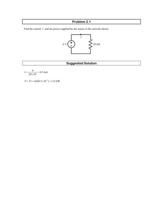
1. Problem 2.1
Find the current I and the power supplied by the source in the network shown.
I
6 V 20 kΩ
Suggested Solution
3
6
0.3 mA
20 10
I = =
×
3
(6)(0.3 10 ) 1.8 mWP VI −
= = × =
2. Problem 2.2
In the circuit shown, find the voltage across the current source and the power absorbed by the resistor.
3 mA 3 kΩ
+
VCS
_
Suggested Solution
( )( )3 3
3 10 3 10 9 VCSV −
= × × =
( )( )3
3 10 9 27 mWP VI −
= = × =
3. Problem 2.3
If the 10- resistor in the network shown absorbs 2.5 mW, find V .kΩ S
VS 10 kΩ
Suggested Solution
2
10 k
SV
P =
Ω
or ( )( )3 3
2.5 10 10 10 5 VS R −
= × = × × =V P
4. Problem 2.4
In the network shown, the power absorbed by xR is 5 mW. Find xR .
Rx
1
mA
2
Suggested Solution
( )
3
2 23
5 10
20 k
0.5 10
x
P
R
I
−
−
×
= = = Ω
×
5. Problem 2.5
In the network shown, the power absorbed by xR is 20 mW. Find xR .
2 mA Rx
Suggested Solution
( )
3
2 23
20 10
5 k
2 10
P
R
I
−
−
×
= = = Ω
×
6. Problem 2.6
A model for a standard two D-cell flashlight is shown. Find the power dissipated in the lamp.
1.5 V
1.5 V
1-Ω lamp
Suggested Solution
1.5 1.5 3 VlampV = + =
( )
22
3
9 W
1
lamp
lamp
lamp
V
P
R
= = =
7. Problem 2.7
An automobile uses two halogen headlights connected as shown. Determine the power supplied by the
battery if each headlight draws 3 A of current.
12 V
Suggested Solution
( )( )12 3 3 72 WSP VI= = + =
8. Problem 2.8
Many years ago a string of Christmas tree lights was manufactured in the form shown in (a). Today the
lights are manufactured as shown in (b). Is there a good reason for this change?
(a)
(b)
Suggested Solution
First of all, one must recognize the fact that a failed lamp becomes an open circuit. Then:
In (a), one faulty lamp would take out the whole string. There would be no way to identify the faulty lamp.
In (b), if one lamp fails, the others stay lit. It is easy to identify the faulty lamp.
9. Problem 2.9
Find 1I in the network shown.
I1
12 mA
4 mA
2 mA
Suggested Solution
I1
12 mA
4 mA
2 mA
I2
2 0.004 0.002 0.006 AI = + =
1 20.012 I I= +
1 6 mAI⇒ =
10. Problem 2.10
Find 1I and 2I in the circuit shown.
I3 = 5 mA
IS
I4 = 6 mA
I1
I6 = 3 mA I2
Suggested Solution
By KCL, 1 4 6 mAI I= =
Also, 6 2 4I I I+ =
or 20.003 0.006I+ =
2 3 mAI⇒ =
11. Problem 2.11
Find xI and yI in the network shown.
4 mA
12 mA 8 mA
Ix Iy
Suggested Solution
0.012 0.004 xI= +
8 mAxI⇒ =
0.004 0.008yI= +
4 mAyI⇒ = −
12. Problem 2.12
Find xI , yI and zI in the circuit shown.
Ix
Iy
Iz2 mA
12 mA
4 mA
Suggested Solution
Ix
Iy
Iz2 mA
12 mA
4 mA
0.012 0.004xI + =
8 mAxI⇒ = −
0.004 0.002 0.012yI + = +
10 mAyI⇒ =
0.004 0.002zI + =
2 mAzI⇒ = −
13. Problem 2.13
Find xI in the circuit shown.
1 mA
4 mA
2 Ix
Ix
Suggested Solution
1 mA
4 mA
2 Ix
Ix
0.001 0.004 2x xI I+ = +
3 mAxI⇒ = −
14. Problem 2.14
Find xI , yI and zI in the network shown.
12 mA
3 mA
2 mA
4 mA
Ix
Iy
Iz
Suggested Solution
12 mA
3 mA
2 mA
4 mA
Ix
Iy
Iz
0.003 0.012xI + =
9 mAxI⇒ =
0.012 0.002 0.004yI + + =
10 mAyI⇒ = −
0.004 0.002zI + =
2 mAzI⇒ = −
15. Problem 2.15
Find xI in the circuit shown.
2Ix
Ix
2 mA
6 mA
Suggested Solution
2Ix
Ix
2 mA
6 mA
2 0.002 0.006x xI I+ = +
4 mAxI⇒ =
16. Problem 2.16
Find xI in the network shown.
1 mA
4 Ix
Ix
6 mA
Suggested Solution
1 mA
4 Ix
Ix
6 mA
4 0.001 0.006x xI I+ = +
5
mA
3
xI⇒ =
17. Problem 2.17
Find xV in the circuit shown.
9 V
+ Vx -
2 Vx
Suggested Solution
KVL: 9 2xV V− + + = 0
3 VxV⇒ =
18. Problem 2.18
Find V in the circuit shown.bd
a
b
c
d
12 V
6 V
+
2 V
_
+ 4 V -
Suggested Solution
KVL: 12 4 0bdV− + + =
8 VbdV⇒ =
19. Problem 2.19
Find V in the network shown.ad
a
b
c
de
4 V 12 V
- 3 V + - 2 V +
+ 3 V -
Suggested Solution
KVL: 4 3adV− + − = 0
7 VadV⇒ =
20. Problem 2.20
Find V and V in the circuit shown.af ec
a b c d
efg
_
2 V
+
- 2 V +
+ 1 V -
12 V 3 V
+
3 V
_
- 1 V +
Suggested Solution
KVL: 2 2afV+ + = 0
4 VafV⇒ = −
KVL: 3 3 0ecV + + =
6 VecV⇒ = −
21. Problem 2.21
Find V in the circuit shown.ac
a
b
c
d
12 V
+ 4 V -
3 Vx
+
Vx = 2 V
_
Suggested Solution
KVL: 2 12 0acV + − =
10 VacV⇒ =
22. Problem 2.22
Find V and V in the circuit shown.ad ce
a b c
de
4 Vx 12 V
- 1 V +
- +
Vx = 2 V
+ 1 V -
Suggested Solution
KVL: 12 2 1 0adV − + + =
9 VadV⇒ =
KVL: 1 12 0ceV + − =
11 VceV⇒ =
23. Problem 2.23
Find V in the network shown.ab
a b
c
12 V
3 Ω
6 Ω
Suggested Solution
Using voltage division,
3
12 4 V
3 6
abV
= =
+
24. Problem 2.24
Find V in the network shown.bd
12 V
3 kΩ 1 kΩ
4 V
a
b
c
d
Suggested Solution
12 V
3 kΩ 1 kΩ
4 V
a
b
c
d
I
12 4
2 mA
3000 1000
I
−
= =
+
KVL: 4 1000(0.002) 0bdV − − =
6 VbdV⇒ =
25. Problem 2.25
Find xV in the circuit shown.
24 V
6 V
2 kΩ
5 kΩ
2 kΩ
+
Vx
_
Suggested Solution
Using voltage division,
( )
5000
24 6 10 V
2000 5000 2000
xV
= −
+ +
=
26. Problem 2.26
Find xV in the circuit shown.
_
Vx
+
6 V
4 kΩ 6 kΩ
24 V
8 V
Suggested Solution
Using voltage division,
( )
4000
6 8 24 4 V
4000 6000
xV
= + −
+
= −
27. Problem 2.27
Find xV in the network shown.
+
Vx
_
5 Ω
3 Vx
15 Ω
5 V
Suggested Solution
+
Vx
_
5 Ω
3 Vx
15 Ω
5 V
I
KVL: , where V I5 15 3 0x xI V V− + − + = 5x =
Therefore, ( )5 15 3 5 5 0I I I− + − + =
1 AI⇒ =
5 VxV∴ =
28. Problem 2.28
Find V in the network shown.1
+
V1
_
+ Vx -
5 V
20 kΩ 40 kΩ
2
xV
Suggested Solution
+
V1
_
+ Vx -
5 V
20 kΩ 40 kΩ
2
xV
I
KVL: 20000 40000 5 0
2
xV
I I− + + + = , where V I40000x =
Therefore,
40000
20000 40000 5 0
2
I
I I− + + + =
0.125 mAI⇒ = −
1 5 40000 5 5 5 0 VxV V I= + = + = − + =
29. Problem 2.29
Find the power absorbed by the resistor in the circuit shown.30-kΩ
30 kΩ
12 V
2 Vx
10 kΩ
+
Vx
_
Suggested Solution
30 kΩ
12 V
2 Vx
10 kΩ
+
Vx
_
I
KVL: where V I12 30000 2 0x xI V V− + + + = 10000x =
Therefore, ( )12 30000 2 10000 10000 0I I− + + + =I
200 AI µ⇒ =
( ) ( ) ( )
22 6
30k 30000) 200 10 30000 1.2 mWP I −
Ω = = × =
30. Problem 2.30
Find oI in the network shown.
12 mA 2 kΩ 6 kΩ 3 kΩ
Io
Suggested Solution
( )
1
2000 12 mA 6 mA
1 1 1
2000 6000 3000
oI
= =
+ +
31. Problem 2.31
Find oI in the circuit shown.
120 mA 4 kΩ 4 kΩ
8 kΩ
Io
Suggested Solution
Using current division,
( )
1
4000 0.120 90 mA
1 1
4000 8000 4000
oI
= =
+
+
32. Problem 2.32
Find oI in the network shown.
6 kΩ
12 mA
12 kΩ 12 kΩ
Io
Suggested Solution
Using current division,
( )
1
12000 0.012 3 mA
1 1 1
6000 12000 12000
oI
= − = −
+ +
33. Problem 2.33
Find V in the circuit shown.o
24 mA 8 kΩ
6 kΩ
6 kΩ
8 kΩ
+
Vo
_
Suggested Solution
Combining the 8- resistors in parallel yields the following circuit.kΩ
24 mA 4 kΩ
6 kΩ
6 kΩ
+
Vo
_
I
Using current division,
( )
1
6000 6000 0.024 6 mA
1 1
4000 6000 6000
I
+= =
+
+
Then,
6000 36 VoV I= =
34. Problem 2.34
Find oI in the network shown.
12 mA
3 kΩ 6 kΩ
4 kΩ
2 kΩ
Io
Suggested Solution
Combining the 3- and resistors in parallel yields the following equivalent circuit.kΩ 6-kΩ
12 mA
2 kΩ
4 kΩ
2 kΩ
I1
( )
( )1
4000
0.012 6 mA
4000 2000 2000
I
= =
+ +
Then,
1
6000
4 mA
6000 3000
oI I
= = +
35. Problem 2.35
Determine LI in the circuit shown.
Ix IL
2 kΩ
6 mA
4 kΩ
2
xI
Suggested Solution
Ix IL
2 kΩ
6 mA
4 kΩ
2
xI
+
V1
_
KCL: 0.006 0
2
x
x L
I
I I− + + = , where 1
2000
x
V
I = and 1
4000
L
V
I =
Therefore,
1 1
0.006 0
2000 4000 4000
V V V
− + + =1
1 6 VV⇒ =
Then,
6
1.5 mA
4000
LI = =
36. Problem 2.36
Determine LI in the circuit shown.
6 kΩ
6 mA
3 Ix
3 mA
2 kΩ 3 kΩ
Ix IL
Suggested Solution
6 kΩ
6 mA
3 Ix
3 mA
2 kΩ 3 kΩ
Ix IL
+
V1
_
KCL: 1
0.006 3 0.003 0
6000
x x
V
I I I− + + + + =L , where 1
2000
x
V
I = and 1
3000
L
V
I = .
Therefore,
1 1 1
0.006 3 0.003 0
6000 2000 2000 3000
V V V
− + + + + =
1V
1
6
1.2 V
5
V⇒ = =
and
1.2
0.4 mA
3000
LI = =
37. Problem 2.37
Find in the circuit shown.ABR
A
B
RAB
2 kΩ
2 kΩ
3 kΩ
6 kΩ
12 kΩ
Suggested Solution
The network can be redrawn as shown below.
A
B
RAB
2 kΩ
2 kΩ
3 kΩ 6 kΩ 12 kΩ
C B A
C B A
Then,
At A-A: 6000 12000 4 k= Ω
At B-B: 2000 4000 6 k+ = Ω
At C-C: 3000 6000 2 k= Ω
and
2000 2000 4 kABR = + = Ω
38. Problem 2.38
Find in the circuit shown.ABR
RAB
A
B
5 kΩ
2 kΩ 2 kΩ
2 kΩ2 kΩ2 kΩ
Suggested Solution
RAB
A
B
5 kΩ
2 kΩ 2 kΩ
2 kΩ2 kΩ2 kΩ
D C B A
D C B A
At A-A: 2000 2000 4 k+ = Ω
At B-B:
4
2000 4000 k
3
= Ω
At C-C:
4000 10
2000 k
3 3
+ = Ω
At D-D:
10000
2000 1250
3
= Ω
Then,
5000 1250 6250ABR = + = Ω
39. Problem 2.39
Find in the network shown.ABR
RAB
A
B
6 kΩ
3 kΩ 3 kΩ
8 kΩ
4 kΩ
5 kΩ 4 kΩ
Suggested Solution
The network can be redrawn as shown below.
RAB
A
B
6 kΩ 3 kΩ 3 kΩ 8 kΩ4 kΩ
5 kΩ 4 kΩ
C B A
C B A
At A-A: 4000 8000 12 k+ = Ω
At B-B: 3000 3000 4000 12000 1 k= Ω
At C-C: 5000 1000 6 k+ = Ω
Therefore,
6000 6000 3 kABR = = Ω
40. Problem 2.40
Find in the circuit shown.ABR
RAB
A
B
2 kΩ
4 kΩ
4 kΩ
3 kΩ
6 kΩ
12 kΩ
Suggested Solution
The circuit can be redrawn as shown below.
RAB
A
B
2 kΩ
4 kΩ
4 kΩ
6 kΩ
12 kΩ
3 kΩ
A
B
C
C
At A: 6000 3000 2 k= Ω
At B: 4000 2000 6 k+ = Ω
At C-C: 6000 12000 4 k= Ω
Then,
2000 4000 4000 10 kABR = + + = Ω
41. Problem 2.41
Find in the network shown.ABR
A
B
RAB 6 kΩ
6 kΩ
6 kΩ
2 kΩ
Suggested Solution
The 2- resistor is shorted. Therefore, the network reduces to:kΩ
A
B
RAB 6 kΩ 6 kΩ 6 kΩ
Then,
6000 6000 6000 2 kABR = = Ω
42. Problem 2.42
Find in the circuit shown.ABR
A
B
RAB
12 kΩ
6 kΩ2 kΩ
4 kΩ 12 kΩ
Suggested Solution
The circuit maybe redrawn as follows:
RAB
A
B
4 kΩ
2 kΩ
12 kΩ
12 kΩ
6 kΩ
A
B
At A: 12000 6000 4 k= Ω
At B: 2000 4000 6 k+ = Ω
Then,
4000 6000 12000 2 kABR = = Ω
43. Problem 2.43
Find in the circuit shown.ABR
2 kΩ 2 kΩ
2 kΩ 2 kΩ
2 kΩ2 kΩ
2 kΩ 2 kΩ
4 kΩ 4 kΩ
A
B
RAB
Suggested Solution
Combining each series pair of resistors, the circuit can be redrawn as follows:2-kΩ
⇒
4 kΩ 4 kΩ
4 kΩ4 kΩ
4 kΩ 4 kΩ
A
B
RAB
4 kΩ4 kΩ
2 kΩ 2 kΩ
A
B
RAB
or
hen,
6 kΩ 6 kΩ
A
B
RAB
T
R 6000 6000 3 kAB = = Ω
44. Problem 2.44
Find the range of resistance for the following resistors:
a) with a tolerance of 5%.1 kΩ
b) with a tolerance of 2%.470 Ω
c) with a tolerance of 10%.22 kΩ
Suggested Solution
a) Minimum value = ( )( )1 0.05 1 k 950− Ω = Ω
Ω
Ω
Ω
Ω
Ω
Maximum value = ( )( )1 0.05 1 k 1050+ Ω =
b) Minimum value = ( )( )1 0.02 470 460.6− Ω =
Maximum value = ( )( )1 0.02 470 479.4+ Ω =
c) Minimum value = ( )( )1 0.1 22 k 19.8 k− Ω =
Maximum value = ( )( )1 0.1 22 k 24.2 k+ Ω =
45. Problem 2.45
Given the network shown, find the possible range of values for the current and power dissipated by the
following resistors:
a) with a tolerance of 1%.390 Ω
b) with a tolerance of 2%.560 Ω
I
10 V R
Suggested Solution
Note that
10 V
I
R
= and
( )
2
10 V 100
P
R R
= = .
a) Minimum resistor value = ( )( )1 0.01 390 386.1− Ω = Ω
Maximum resistor value = ( )( )1 0.01 390 393.9+ Ω = Ω
Minimum current value =
10
25.39 mA
393.9
=
Maximum current value =
10
25.90 mA
386.1
=
Minimum power value =
100
253.9 mW
393.9
=
Maximum power value =
100
259 mW
386.1
=
b) Minimum resistor value = ( )( )1 0.02 560 548.8− Ω = Ω
Maximum resistor value = ( )( )1 0.02 560 571.2+ Ω = Ω
Minimum current value =
10
17.51 mA
571.2
=
Maximum current value =
10
18.22 mA
548.8
=
Minimum power value =
100
175.1 mW
571.2
=
Maximum power value =
100
182.2 mW
548.8
=
46. Problem 2.46
Given the circuit shown:
a) Find the required value of .R
b) Use Table 2.1 to select a standard 10% tolerance resistor for .R
c) Calculate the actual value of I .
d) Determine the percent error between the actual value of I and that shown in the circuit.
e) Determine the power rating for the resistor .R
I = 40 mA
510 Ω
100 mA
R
Suggested Solution
a) From KCL, the current in the 510-Ω resistor is 100 mA 40 mA 60 mA− = . From Ohm’s Law,
the voltage across the circuit is ( )( ) 30.6 V=510 60 mAΩ . Therefore, the required value of R is
( ) ( )30.6 V 40 mA 765= Ω .
b) From Table 2.1, the nearest 10% resistor value is 820 Ω .
c) To find the actual value of I, first find the actual voltage across the circuit, which is
( )( )100 mA 510 820 31.44 VΩ Ω = . Then,
31.44 V
38.35 mA
820
I = =
Ω
.
d) The percent error is
( )
( )
38.35 40
100 4.14 %
40
−
= − .
e) Since the power consumption in R is
( )
2
31.44 V
1.206 W
820
=
Ω
, a resistor should be used.2-W
47. Problem 2.47
The resistors and shown in the circuit are 11R 2R Ω with a tolerance of 5% and with a tolerance of
10%, respectively.
2 Ω
a) What is the nominal value of the equivalent resistance?
b) Determine the positive and negative tolerance for the equivalent resistance.
Req
R1
R2
Suggested Solution
a) The nominal value is 1 2 3eqR R R= + = Ω
b) The minimum and maximum values of are1R 0.95 Ω and 1.05 Ω , and the minimum and
maximum values of are 1.82R Ω and 2.2 Ω . Thus, the minimum and maximum values of
are and 1.0
eqR
0.95 1.8 2.75+ = Ω 5 2.2 3.25+ = Ω . The positive and negative tolerances are
Positive Tolerance =
( )
( )
3.25 3
100 8.33 %
3
−
=
Negative Tolerance =
( )
( )
2.75 3
100 8.33 %
3
−
= −
48. Problem 2.48
Find 1I and V in the circuit shown.o
6 V
1 kΩ
12 kΩ 3 kΩ
I1
+
Vo
_
Suggested Solution
From Ohm’s Law: 1
6 V
0.5 mA
12 k
I
−
= = −
Ω
By application of voltage division: ( )
3 k
6 V 4.5 V
3 k 1 k
oV
Ω
= − =
Ω + Ω
−
49. Problem 2.49
Find 1I and V in the circuit shown.o
12 V
2 kΩ
6 kΩ
8 kΩ
4 kΩ
I1
+
Vo
_
Suggested Solution
Combining resistors ( )6 k 8 k +4 k 4 k Ω Ω Ω = Ω reduces the network to the following:
12 V
2 kΩ
4 kΩ
+
V1
_
Using voltage division, then
( )1
4000
12 V 8 V
2000 4000
V
= =
+
.
Looking back at the original circuit,
12 V
2 kΩ
6 kΩ
8 kΩ
4 kΩ
I1
+
Vo
_
+
8 V
_
Ohm’s Law: 1
8 V 4
mA
6 k 3
I = =
Ω
Voltage division: ( )
4000 8
8 V
8000 4000 3
oV
= =
+
50. Problem 2.50
Find 1I in the circuit shown.
12 mA 10 kΩ
2 kΩ
2 kΩ 2 kΩ
2 kΩ
I1
Suggested Solution
The circuit can be simplified as follows:
12 mA 10 kΩ
2 kΩ
I2
( )
4
2 k 2 k +2 k k
3
Ω Ω Ω = Ω
Then, ( )2
10000
0.012 9 mA
4000
10000 2000
3
I
= =
+ +
and
( )
( )1
2000
9 mA 3 mA
2000 2000 2000
I
= =
+ +
51. Problem 2.51
Determine V in the network shown.o
14 kΩ
4 kΩ
9 kΩ
12 kΩ
2 kΩ
2 mA
+
Vo
_
Suggested Solution
The network can be redrawn as:
14 kΩ
4 kΩ
12 kΩ
2 kΩ
2 mA
+
Vo
_
9 kΩ
A
A
The equivalent resistance to the left of A-A is ( )14 k 4 k 9 k 12 k 4 kΩ + Ω Ω Ω = Ω .
4 kΩ
2 kΩ
2 mA
+
Vo
_
Then, V .( )( )2 k 4 k 2 mA 12 Vo = − Ω + Ω = −
52. Problem 2.52
Find V in the network shown.o
2 Ω 8 Ω
2 Ω
4 Ω 4 Ω
24 V
+
Vo
_
Suggested Solution
The network can be redrawn as:
Combining the four resistors on the right-hand side ( ) ( )4 2 8 4 4 Ω + Ω Ω + Ω = Ω yields:
2 Ω
8 Ω
2 Ω
4 Ω
4 Ω
24 V
+
Vo
_
2 Ω
4 Ω
24 V
I1
and
( )1
24 V
4 A
2 4
I = =
Ω + Ω
.
Then, reconsidering the original circuit,
53. 2 Ω 8 Ω
2 Ω
4 Ω 4 Ω
24 V
+
Vo
_
4 A
I2
( )
( ) ( )
( )2
4 2 4
4 A A
4 2 8 4 3
I
+
= =
+ + +
and
( )
4 16
4 A A V
3 3
oV
= − = −
54. Problem 2.53
Find oI in the circuit shown.
9 kΩ 4 kΩ
6 kΩ
6 kΩ
3 kΩ24 V
Io
Suggested Solution
The circuit can be redrawn as:
9 kΩ 4 kΩ
6 kΩ 6 kΩ 3 kΩ24 V
I2
Io
I1
B A
B A
At A-A: 6000 3000 2 k= Ω
At B-B: ( )6000 4000 2000 3 k+ = Ω
The circuit simplifies to:
9 kΩ
3 kΩ24 V
I1
Then,
( )1 2
24 6000
2 mA 1 mA
9000 3000 6000 4000 2000
I I
= = ⇒ = =
+ + +
1I
and 2
3000 1
mA
3000 6000 3
oI I
= =
+
.
55. Problem 2.54
Find V in the circuit shown.o
2 kΩ
2 kΩ4 kΩ
12 kΩ 3 kΩ
6 mA +
Vo
_
Suggested Solution
2 kΩ
2 kΩ4 kΩ
12 kΩ 3 kΩ
6 mA +
Vo
_
A B
A B
At A-A: ( )2000 4000 12000 4 k+ = Ω
At B-B: ( )4000 2000 3000 2 k+ = Ω
Then, V .( )( )2 k 6 mA 12 Vo = Ω =
56. Problem 2.55
Find oI in the network shown.
1 kΩ 10 kΩ 2 kΩ
6 kΩ
3 kΩ
4 kΩ
4 kΩ
6 kΩ
12 V
Io
Suggested Solution
Redrawing the network:
1 kΩ 10 kΩ 2 kΩ
6 kΩ3 kΩ4 kΩ4 kΩ 6 kΩ12 V
Io
D C B A
I1
D C B A
At A-A: 3000 6000 2 k= Ω
At B-B: ( )4000 2000 2000 2 k+ = Ω
At C-C: ( )6000 10000 2000 4 k+ = Ω
At D-D: 4000 4000 2 k= Ω
1
12
4 mA
1000 2000
I = =
+
Using current division, 1
4000
2 mA
4000 4000
oI I
= = +
57. Problem 2.56
Find V in the network shown.o
6 kΩ
9 kΩ 8 kΩ
4 kΩ4 kΩ
12 mA
+
Vo
_
Suggested Solution
6 kΩ
9 kΩ 8 kΩ
4 kΩ4 kΩ
12 mA
+
Vo
_
I1 I2
A
A
At A-A: ( )4000 8000 4000 3 k+ = Ω
Using current division,
( )1
6000
0.012 4 mA
6000 9000 3000
I
= =
+ +
Again using current division,
( )2 1
4000
1 mA
4000 8000 4000
I I
= =
+ +
Then, V .24000 4 Vo I= =
58. Problem 2.57
Find oI in the circuit shown.
6 kΩ
6 kΩ
2 kΩ 4 kΩ
12 V
Io
3 kΩ
Suggested Solution
The circuit can be redrawn as:
⇒12 V
At A-A: ( )2000 2000 4000 2 k+ = Ω
6 kΩ
6 kΩ
2 kΩ 4 kΩ
Io
3 kΩ
6 kΩ
2 kΩ
2 kΩ 4 kΩ
12 V
Io
I1
A
A
1
12
1.5 mA
6000 2000
I = =
+
Using current division,
( )
( ) 1
2000 2000
0.75 mA
2000 2000 4000
oI I
+
= =
+ +
59. Problem 2.58
If V in the network shown, find V .4 Vo = S
VS
8 kΩ
4 kΩ
+
Vo = 4 V
_
Suggested Solution
VS
8 kΩ
4 kΩ
+
Vo = 4 V
_
I
4
1 mA
4000 4000
oV
I = = =
Then, V I .8000 8 4 12 VS oV= + = + =
60. Problem 2.59
If the power absorbed by the resistor in the network shown is 36 mW, find4-kΩ oI .
9 kΩ
12 kΩ 4 kΩ
Io
Suggested Solution
9 kΩ
12 kΩ 4 kΩ
Io
+
V1
_
2
1
4 k 136 mW 12 V
4 k
V
P VΩ = = ⇒ =
Ω
12 V
1 mA
12 k
oI = =
Ω
61. Problem 2.60
If the power absorbed by the resistor in the circuit shown is 36 mW, find V .4-kΩ S
VS
9 kΩ
12 kΩ 4 kΩ
Suggested Solution
VS
9 kΩ
12 kΩ 4 kΩ
+
V1
_
I2 I1
Io
2
1
4 k 136 mW 12 V
4000
V
P VΩ = = ⇒ =
1
1 mA
12 k
o
V
I = =
Ω
1
1 3 mA
4 k
V
I = =
Ω
2 1 1 mA 3 mA 4 mAoI I I= + = + =
( ) 2 19 k 48 VSV I V= Ω + =
62. Problem 2.61
In the network shown, the power absorbed by the 4-Ω resistor is 100 W. Find V .S
VS
3 Ω
4 Ω
7 Ω
3 Ω
Suggested Solution
VS
3 Ω
4 Ω
7 Ω
3 Ω
+
V1
_
I1
I2I3
( )2
4 1 14 100 W 5 AP I IΩ = Ω = ⇒ =
1 14 20V I= = V
1
2 2 A
7 3
V
I = =
Ω + Ω
3 1 2 7 AI I I= + =
13 21 20 4S SV I V= + = + = 1 V
63. Problem 2.62
In the network shown, V . Find6 Vo = SI .
4 kΩ
8 kΩ 4 kΩ
2 kΩ
IS
+
Vo
_
Suggested Solution
4 kΩ
8 kΩ 4 kΩ
2 kΩ
IS
+
Vo
_
+
VS
_
I1I2
1
6
3 mA
2 k 2000
oV
I = = =
Ω
( ) 14 k 12 6 18 VS oV I V= Ω + = + =
2
18
1.5 mA
8 k 4 k 12000
SV
I = = =
Ω + Ω
1 2 3 mA 1.5 mA 4.5 mASI I I= + = + =
64. Problem 2.63
In the circuit shown, 4 mAI = . Find V .S
2 kΩ
6 kΩ
5 kΩ
3 kΩVS
I
Suggested Solution
2 kΩ
6 kΩ
5 kΩ
3 kΩVS
I
+
V1
_
I2 I1
( )1 6 k 24 VV I= Ω =
1
1
24
3 mA
5 k 3 k 8000
V
I = = =
Ω + Ω
2 1 0.004 0.003 7 mAI I I= + = + =
( ) 2 12 k 14 24 38 VSV I V= Ω + = + =
65. Problem 2.64
In the circuit shown, . Find2 mAoI = SI .
4 kΩ
4 kΩ 2 kΩ
6 kΩ
1 kΩ
2 kΩ
IS
Io
Suggested Solution
4 kΩ
4 kΩ 2 kΩ
6 kΩ
1 kΩ
2 kΩIS
Io
+
V1
_
+ V2 -
+
V3
_
I3
I2
I1
( )1 6 k 12 VoV I= Ω =
1
1
12
4 mA
1 k 2 k 3000
V
I = = =
Ω + Ω
2 1 0.002 0.004 6 mAoI I I= + = + =
( )2 22 k 12 VV I= Ω =
3 2 1 12 12 24 VV V V= + = + =
3
3
24
3 mA
4 k 4 k 8000
V
I = = =
Ω + Ω
3 2 0.003 0.006 9 mASI I I= + = + =
66. Problem 2.65
In the network shown, V . Find V .1 12 V= S
2 kΩ
6 kΩ
4 kΩ
4 kΩ
1 kΩ
3 kΩVS
+ V1 -
Suggested Solution
2 kΩ
6 kΩ
4 kΩ
4 kΩ
1 kΩ
3 kΩVS
+ V1 -+
V2
_
A
A
I2
I1I3
At A-A: ( )4000 1000 3000 2 k+ = Ω
1
1
12
3 mA
4 k 4000
V
I = = =
Ω
( )2 1 12 k 12 6 18 VV V I= + Ω = + =
2
2
18
3 mA
6 k 6000
V
I = = =
Ω
3 1 2 0.003 0.003 6 mAI I I= + = + =
( ) 3 22 k 12 18 30 VSV I V= Ω + = + =
67. Problem 2.66
In the circuit shown, V . Find2 Vo = SI .
IS
10 Ω
12 Ω 2 Ω
3 Ω
8 Ω
4 Ω
+
Vo
_
Suggested Solution
IS
10 Ω
12 Ω 2 Ω
3 Ω
8 Ω
4 Ω
+
Vo
_
+
V1
_
+
V2
_
I1
I2
I3I4
1
2
0.5 A
4 4
oV
I = = =
Ω
( )1 18 6 VoV I V= Ω + =
1
2 2 A
3
V
I = =
Ω
3 2 1 2.5 AI I I= + =
( )2 3 12 11 VV I V= Ω + =
2
4 0.5 A
10 12
V
I = =
Ω + Ω
3 4 2.5 0.5 3 ASI I I= + = + =
68. Problem 2.67
In the network shown, V . Find6 Vo = SI .
IS 9 kΩ
3 kΩ
2 kΩ
1 kΩ
5 kΩ
+
Vo
_
Suggested Solution
IS 9 kΩ
3 kΩ
2 kΩ
1 kΩ
5 kΩ
+
Vo
_
+ V1 -
+
V2
_
I1
I2
I3
I4
1
6
3 mA
2 k 2000
oV
I = = =
Ω
2
6
1 mA
1 k 5 k 6000
oV
I = = =
Ω + Ω
3 1 2 0.003 0.001 4 mAI I I= + = + =
( )1 33 k 12 VV I= Ω =
2 1 12 6 18 VoV V V= + = + =
2
4
18
2 mA
9 k 9000
V
I = = =
Ω
3 4 0.004 0.003 6 mASI I I= + = + =
69. Problem 2.68
In the circuit shown, . Find2 AoI = SI .
8 Ω
4 Ω
4 Ω3 ΩIS
Io
6 V
Suggested Solution
8 Ω
4 Ω
4 Ω3 ΩIS
Io
6 V
+
V1
_
+
V2
_
I1I2I3
( )1 3 6 VoV I= Ω =
1
1
6
1.5 A
4 4
V
I = = =
Ω
2 1 2 1.5 3.5 AoI I I= + = + =
2 16 V 6 6 12 VV V= + = + =
2
3
12
1 A
8 4 12
V
I = =
Ω + Ω
=
2 3 3.5 1 4.5 ASI I I= + = + =
70. Problem 2.69
If in the circuit shown, find4 mAoI = SI .
10 kΩ
1 kΩ
4 kΩ
2 kΩ
12 V
IS
Io
Suggested Solution
10 kΩ
1 kΩ
4 kΩ
2 kΩ
12 V
IS
Io
+
V1
_
+ V2 -
+
V3
_
I1
I2
I3
( )1 4 k 12 V 16 12 4 VoV I= Ω − = − =
1
1
4
2 mA
2 k 2000
V
I = = =
Ω
2 1 0.004 0.002 6 mAoI I I= + = + =
( )2 21 k 6 VV I= Ω =
3 2 1 6 4 10 VV V V= + = + =
3
3
10
1 mA
10 k 10000
V
I = = =
Ω
2 3 0.006 0.001 7 mASI I I= + = + =
71. Problem 2.70
Find oI in the circuit shown.
12 kΩ
2 kΩ
12 kΩ
12 kΩ
8 kΩ
I1 = 5 mA
Io
9 mA
Suggested Solution
12 kΩ
2 kΩ
12 kΩ
12 kΩ
8 kΩ
I1 = 5 mA
Io
9 mA
_
V1
+
+ V3 -
_
V2
+
I2
I3
1 2 29 mA 4 mAI I I+ = ⇒ =
( )1 112 k 60 VV I= Ω =
( )2 212 k 48 VV I= Ω =
3 1 2 60 48 12 VV V V= − = − =
3
3
12
1 mA
12 k 12000
V
I = = =
Ω
1 3 0.005 0.001 6 mAoI I I= + = + =
72. Problem 2.71
Find V in the circuit shown.o
12 kΩ
4 kΩ 6 kΩ 18 kΩ
6 kΩ
42 VI1 = 4 mA
+
Vo
_
Suggested Solution
12 kΩ
4 kΩ 6 kΩ 18 kΩ
6 kΩ
42 VI1 = 4 mA
+
Vo
_
+ V3 -
_
V2
+
+
V1
_
I3
I2
( )1 14 k 16 VV I= Ω =
2 142 V 42 16 26 VV V= − = − =
2
2
26 13
mA
6 k 6000 3
V
I = = =
Ω
3 2 1
13 1
mA 4 mA mA
3 3
I I I= − = − =
( )3 312 k 4 VV I= Ω =
1 3 16 4 12 VoV V V= − = − =
73. Problem 2.72
Find the power absorbed by the network shown.
12 kΩ
6 kΩ 6 kΩ
2 kΩ 18 kΩ
21 V
Suggested Solution
Redrawing the network:
Y∆ →
⇒
12 kΩ
2 kΩ 6 kΩ
18 kΩ 6 kΩ
21 V
3 kΩ
2 kΩ 6 kΩ
6 kΩ 2 kΩ
21 V
The equivalent resistance seen by the source is:
( ) ( )2 k 6 k 6 k 2 k 3 k
4 k 3 k
7 k
eqR = Ω + Ω Ω + Ω +
= Ω + Ω
= Ω
Ω
Then,
( )
2
21 V 441
63 mA
7000eq
P
R
= = =
74. Problem 2.73
Find oI in the circuit shown.
2 Ω
3 Ω
4 Ω
5 Ω
18 Ω
12 Ω
9 Ω
36 V
Io
12 Ω
Suggested Solution
Note that the four right-most resistors can be combined as ( )3 4 5 12 6Ω + Ω + Ω Ω = Ω . Then the circuit
can be redrawn as:
Y∆ →
⇒
Io
36 V
9 Ω
3 Ω 2 Ω
2 Ω
6 Ω
I
Io
36 V
9 Ω
18 Ω 12 Ω
2 Ω
6 Ω
( ) ( )
36 V
4 A
9 3 2 2 6
I = =
Ω + Ω Ω + Ω + Ω
( )
( ) ( )
9 3
3 A
9 3 2 2
oI I
+
= =
+ + +
75. Problem 2.74
Find oI in the circuit shown.
Suggested Solution
Applying the transformation to the three 12-Y∆ → Ω resistors yields:
12 Ω
5 Ω
12 Ω
12 Ω
14 Ω
12 V
Io
5 Ω 14 Ω
12 V
Io
4 Ω 4 Ω
4 Ω
Ix
( )
( ) ( )
4 14
4 5 4 14
o xI I
+
= −
+ + +
where
( ) ( )
12 V 12
1.2 A
104 4 5 4 14
xI = =
Ω + Ω + Ω Ω + Ω
=
18 12 4
0.80 A
27 10 5
oI∴ = − = − ≈ −i
76. Problem 2.75
Find oI in the circuit shown.
Io
12 Ω
6 Ω
4 Ω
18 Ω
6 Ω
12 A
Suggested Solution
Converting the to a Y yields the circuit:∆
Io
4 Ω 6 Ω
12 A
3 Ω
2 Ω 6 Ω
( )
( ) ( )
( )
2 4
12 A 4 A
2 4 6 6
oI
+
= =
+ + +
77. Problem 2.76
Find oI in the circuit shown.
4 Ω
4 Ω
4 Ω
12 Ω
12 Ω
Io
12 A
Suggested Solution
Applying the transformation:Y → ∆
12 A
⇒
12 Ω
12 Ω
12 Ω
Io
12 Ω
12 Ω
I Io
12 A 12 Ω
12 Ω
12 Ω
12 Ω
12 Ω
The circuit can be further simplified to:
I
12 A
12 Ω
12 Ω
12 A
6 A
2
I = =
3 A
2
o
I
I = =
78. Problem 2.77
Find oI in the circuit shown.
12 Ω 12 Ω
6 Ω
6 Ω 6 Ω
6 Ω
12 V
Io
Suggested Solution
Combining the two 12-Ω resistors yields:
6
Y∆ →
⇒
6 Ω
Ω
Ω 6 Ω
6 Ω
12 V
Io
6 Ω
6 Ω 2 Ω
2 Ω
12 V
Io
2 Ω
6
The circuit can be further simplified to the following:
⇒
I
12 V
o
2 Ω
8 Ω
8 Ω
12 V
Io
2 Ω
4 Ω
12 V
2 A
6
oI = =
Ω
79. Problem 2.78
Find V in the circuit shown.o
12 V
+
Vo
_
IS
2000 IS
3 kΩ
5 kΩ
Suggested Solution
KVL: 12 3000 2000 5000 0S S SI I I− + − + =
2 mASI⇒ =
5000 10 Vo SV I= =
80. Problem 2.79
Find V in the network shown.o
12 V
2 kΩ
2 Vo
2 kΩ
+
Vo
_
Suggested Solution
12 V
2 kΩ
2 Vo
2 kΩ
+
Vo
_
I
KVL: where V I12 2000 2 0o oI V V− + + + = 2000o =
Therefore,
12 2000 4000 2000 0I I I− + + + =
1.5 mAI⇒ =
( )3
2000 1.5 10 3 VoV −
= × =
81. Problem 2.80
Find V in the network shown.o
5 mA 2 kΩ 1 kΩ2 Ix
Ix
+
Vo
_
Suggested Solution
KCL: 0.005 2 0
2000 1000
o o
x
V V
I− + + + = where
2 k
o
x
V
I =
Ω
Therefore,
0.005 2 0 2 V
2000 2000 1000
o o o
o
V V V
V− + + + = ⇒ =
82. Problem 2.81
Find oI in the network shown.
Io
+
Vx
_
5 A 3 Vx6 Ω
4 Ω
8 Ω
Suggested Solution
Io
+
Vx
_
5 A 3 Vx6 Ω
4 Ω
8 Ω
+
V1
_
KCL: 1 1
5 3 0
6 8 4
x
V V
V+ − + =
+
where 1
1
4
8 4 3
x
V
V V= =
+
Therefore,
1 1 1
5 3 0
6 12 3
V V V
+ − + =
1 4 VV⇒ =
1 4 2
A
6 6 3
o
V
I = = =
Ω
83. Problem 2.82
Find V in the circuit shown.o
6 kΩ
2 kΩ
1 kΩ
+
Vo
_
4 mA
2000
oV
Suggested Solution
6 kΩ
2 kΩ
1 kΩ
+
Vo
_
4 mA
2000
oV
+
V1
_
KCL: 1 1
0.004 0
6000 2000 2000 1000
oVV V
− − + =
+
where 1
1
1000
2000 1000 3
o
V
V V= =
+
Therefore,
3 3
0.004 0
6000 2000 3000
o o oV V V
− − + =
4 VoV⇒ =
84. Problem 2.83
A single-stage transistor amplifier is modeled as shown. Find the current in the load LR .
+
VS = 250 mV
_
RS = 1 kΩ Rb = 250 Ω
Ib
110 Ib
Ro = 4 kΩ
RL = 400 Ω
Io
Suggested Solution
0.25
0.2 mA
1000 250
S
b
S b
V
I
R R
= = =
+ +
( )
4000
110 100 20 mA
4000 400
o b bI I I
= − = − = −
+
85. Problem 2.84
A typical transistor amplifier is shown. Find the amplifier gain G (i.e., the ratio of the output voltage to
the input voltage).
250 mVSV =
5
3.5 10 bI×
100 Ω
5 kΩ
500 Ω
Ib
5 kΩ
300 Ω
+
Vo
_
Suggested Solution
250 mVSV =
5
3.5 10 bI×
100 Ω
5 kΩ
500 Ω
Ib
5 kΩ
300 Ω
+
Vo
_
I1
( )1
0.25
451 A
554.5100 5 k 500
SV
I µ= =
Ω + Ω Ω
=
1
5000
409.8 A
5000 500
bI I µ
= =
+
( )5300
3.5 10 8.12 V
300 5000
o bV I
= − × = − +
8.12
32.5
0.250
o
S
V
G
V
−
= ≈ −
86. Problem 2.85
For the network shown, choose the values of and such that V is maximized. What is the resulting
ratio,
inR oR o
o SV V ?
VS
RS
Rin
Ro
RLµ Vin
+
Vin
_
+
Vo
_
Suggested Solution
in
in S
S in
R
V V
R R
=
+
( ) inL L
o in
o L S in o L
RR R
V V
R R R R R R
µ µ
= =
+ +
SV
+
Therefore,
o in L
S S in o
V R R
V R R R R
µ
=
+ + L
Clearly, to maximize o
S
V
V
, we must maximize . This is becauseinR in
S i
R
R R+ n
is always less than 1, but gets
closer and closer to 1 as is made larger and larger.inR
On the other hand, to maximize o
S
V
V
, we must minimize . This is becauseoR L
o L
R
R R+
is always less than
1, but gets closer and closer to 1 as is made smaller and smaller.oR
In the limit,
0 0
lim lim lim lim 1 1
in o in o
o in L
R R R R
S S in o L
V R R
V R R R R
µ µ µ
→∞ → →∞ →
= =
+ +
× × =
87. Problem 2.86
In many amplifier applications we are concerned not only with voltage gain, but also with power gain.
( ) ( )Power gain = = power delivered to the load power delivered by the inputpA
Find the power gain for the circuit shown, where 50 kLR = Ω .
VS
+
V
_
8 kinR = Ω
2 kSR = Ω
V/100
100 koR = Ω
50 kLR = Ω
+
Vo
_
Suggested Solution
VS
+
V
_
8 kinR = Ω
2 kSR = Ω
V/100
100 koR = Ω
50 kLR = Ω
+
Vo
_
IS Io
8000
0.8
8000 2000
S SV V
= =
+
V
3100,000
5.33 10
100,000 50,000 100
o S
V
I V−
= − = − ×
+
( ) ( )
22 3
5.33 10 50,000) 1.422load o L S SP I R V V−
= = × = 2
2
8000 2000 10,000
S S
in S S S
V V
P V I V
= = = +
2
3
2
1.422
14.22 10
10,000
load S
p
in S
P V
A
P V
= = = ×
88. Problem 2.87
Find the power absorbed by the 10- resistor in the circuit shown.kΩ
11 mA 2 kΩ
4 kΩ 4 kΩ
3 kΩ
10 kΩ
+
Vx
_
+
Vo
_
2000
xV
Suggested Solution
Combining the two resistors in parallel yields the following simplified circuit:4-kΩ
11 mA 2 kΩ
2 kΩ
3 kΩ
10 kΩ
+
Vx
_
+
Vo
_
2000
xV
0.011 0
2 k 2000 2 k 3 k 10 k
o x o oV V V V
− + + + + =
Ω Ω + Ω Ω
where
3000
0.6
2000 3000
x o o
= =
+
V V V
Therefore,
3
0.011 0 10 V
2000 10,000 5000 10,000
o o o o
o
V V V V
V− + + + + = ⇒ =
( )
22
10 k
10
10 mW
10 k 10,000
oV
P Ω = = =
Ω
89. Problem 2.88
Find the power absorbed by the 12- resistor in the circuit shown.kΩ
6 mA 6 kΩ
3 Io
6 kΩ 3 kΩ
4 kΩ
12 kΩ
Io
+
Vo
_
Suggested Solution
6 mA 6 kΩ
3 Io
6 kΩ 3 kΩ
4 kΩ
12 kΩ
Io
+
Vo
_
I1
( )
0.006 3 0
6 k 12 k4 k 6 k 3 k
o o
o
V V
I− + + + + =
Ω ΩΩ + Ω Ω
oV
where 1 1
6000 2
6000 3000 3
oI I I
= =
+
( )1
2
6000 3 6000 90004 k 6 k 3 k
o o o
o
V V V
I I
= = ⇒ =
Ω + Ω Ω
oV
=
Then, substituting:
0.006 3 0 8 V
6000 9000 6000 12,000
o o o o
o
V V V V
V
− + + + + = ⇒ =
2
0
12 k
64
5.33 mW
12 k 12,000
V
P Ω = = =
Ω
90. Problem 2FE-1
Find the power generated by the source in the network shown.
5 kΩ
6 kΩ 18 kΩ
12 kΩ
4 kΩ 6 kΩ
120 V
Suggested Solution
Applying the transformation yields:Y∆ →
⇒
5 kΩ
4 kΩ 6 kΩ
120 V
3 kΩ
2 kΩ 6 kΩ
5 kΩ
120 V
3 kΩ
4 kΩ
I
120 V
10 mA
12 k
I = =
Ω
( )120 V 120 0.010 1.2 WP I= = × =
91. Problem 2FE-2
Find the equivalent resistance of the circuit shown at the terminals -A B .
A
B
RAB
12 kΩ
6 kΩ
6 kΩ
4 kΩ
12 kΩ
12 kΩ
12 kΩ
Suggested Solution
Combining resistors,
12 k 6 k 4 kΩ Ω = Ω
( )12 k 12 kΩ 12 kΩ 8 kΩ + = Ω
The circuit is now reduced to:
A
B
RAB
4 kΩ
6 kΩ
4 kΩ
8 kΩ
and further to:
A
B
RAB
4 kΩ
( )6 k 8 k 4 k 4 kΩ Ω+ Ω = Ω
Therefore,
4 k 4 k 8 kABR = Ω + Ω = Ω
92. Problem 2FE-3
Find the voltage V in the network shown.o
24 mA
1 kΩ 2 kΩ
6 kΩ3 kΩ
6 kΩ
12 kΩ
+
Vo
_
Suggested Solution
Combining resistors:
1 k 3 k 4 kΩ + Ω = Ω
6 k 12 k 4 kΩ Ω = Ω
The network is now reduced to:
24 mA
2 kΩ
6 kΩ4 kΩ
4 kΩ
+
Vo
_
I
Using current division,
( )
( )
4000
24 mA 6 mA
4000 2000 6000 4000
I
= =
+ + +
( )6 k 36 VoV I= Ω =
93. Problem 2FE-4
Find the current oI in the circuit shown.
Io
3 kΩ
3 kΩ 6 kΩ6 kΩ
6 kΩ
12 kΩ
4 kΩ
12 V
Suggested Solution
Combining resistors:
3 k 6 k 9 kΩ + Ω = Ω
3 k 6 k 2 kΩ Ω = Ω
Thus, the circuit simplifies to:
⇒ ⇒9 k
2 kΩ
6 kΩ
9 kΩ
12 kΩ
4 kΩ
12 V
Ix
I
18 kΩ
6 kΩ
Ω
12 V
Ix
I
6 kΩ
12 V
6 kΩ
I
12V
1 mA
6 k 6 k
I = − = −
Ω + Ω
9000 1
mA
9000 18,000 3
xI I
= =
+
−
6000 2
mA
3000 6000 9
o xI I
= =
+
−