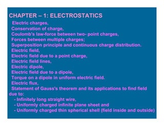
1. The document discusses concepts from electrostatics including electric charges, Coulomb's law, electric fields, and frictional electricity.
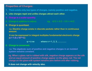
2. Key topics covered include the electric field due to point charges and dipoles, Gauss's law and its applications, and properties of charges such as quantization and conservation of charge.
3. Frictional electricity is produced by rubbing two materials together, causing a transfer of electrons between them. This leaves one material positively charged and the other negatively charged.


![Electric Field Intensity due to an Electric Dipole:
i) At a point on the axial line:
Resultant electric field intensity
at the point P is
E = E + E
P A B
The vectors EA and EB are
collinear and opposite.
1
i
EA =
(x + l)2
q
(x - l)2
4πε0
1
i
EB =
│EP │ = │EB│ - │EA│
q
P
│E │ =
q
(x + l)2
q
(x - l)2
4πε0
1
4πε0
]
[ -
│EP │ =
4π ε0
1 2 (q . 2l) x
(x2 – l2)2
│EP │ =
1
4π ε
2 p x
0 (x – l )
2 2 2
If l << x, then
EP ≈
2 p
4π ε0
x3
The direction of electric field intensity
at a point on the axial line due to a
dipole is always along the direction of
the dipole moment.
l
l
x
P
EP = EB - EA
- q + q
p
A B EA EB
O
EP =
1
4π ε0
2 p x
(x2 – l2)2
i](https://image.slidesharecdn.com/chapter-1ecf-230731121952-bea54ba3/85/Chapter-1-ECF-pptx-24-320.jpg)