Downloaded 68 times

![COSMOS: Complete Online Solutions Manual Organization System
Vector Mechanics for Engineers: Statics and Dynamics, 8/e, Ferdinand P. Beer, E. Russell Johnston, Jr.,
Elliot R. Eisenberg, William E. Clausen, David Mazurek, Phillip J. Cornwell
© 2007 The McGraw-Hill Companies.
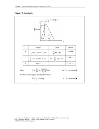
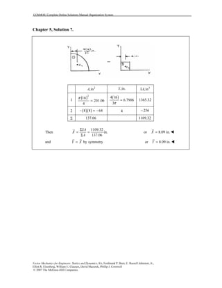
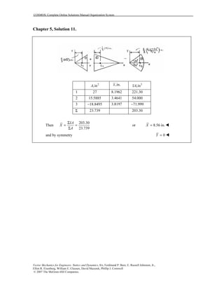
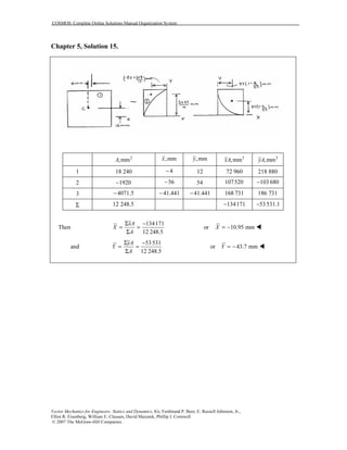
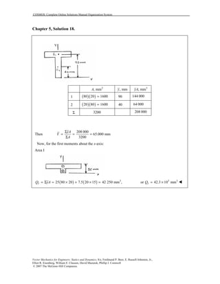
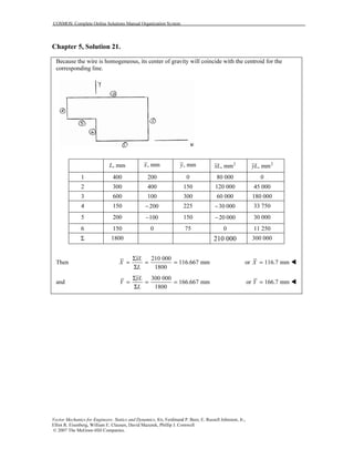
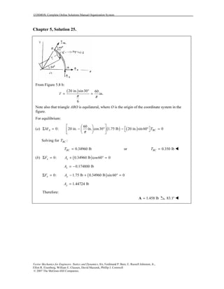
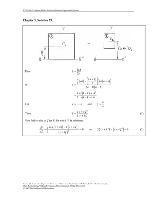
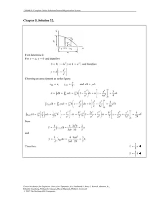
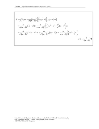
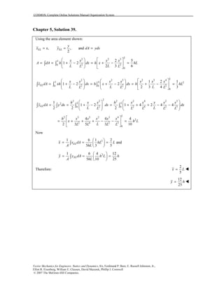
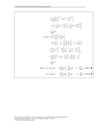
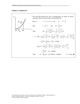
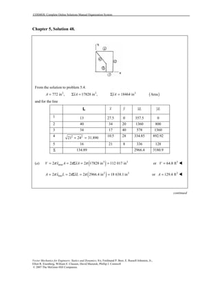
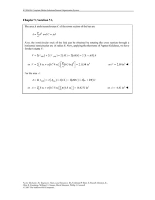
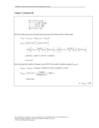
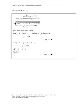
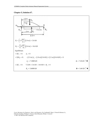
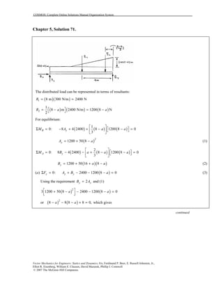
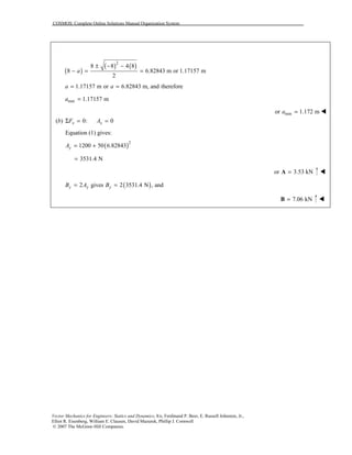
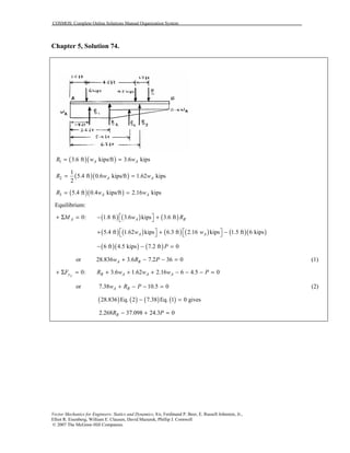
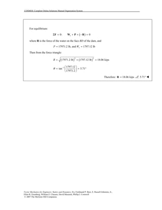
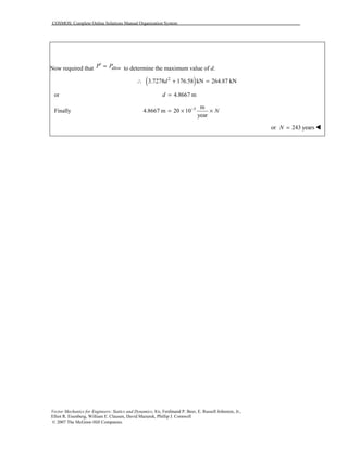
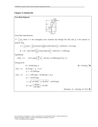
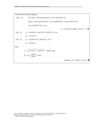
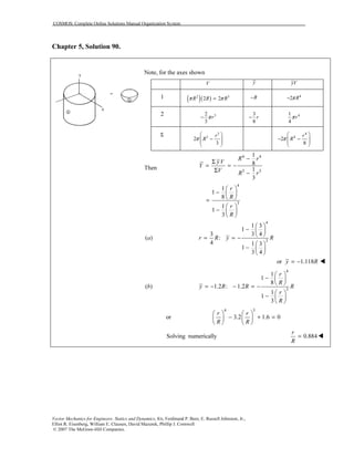
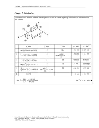
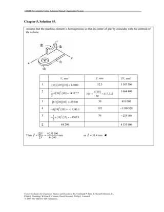
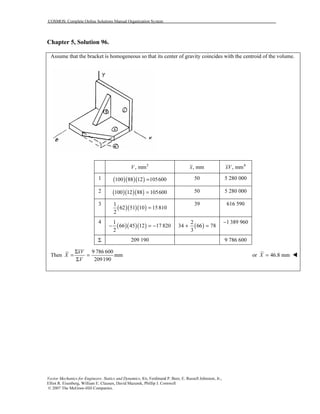
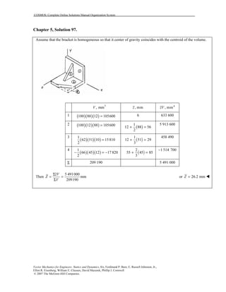
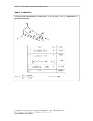
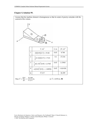
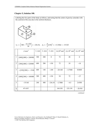
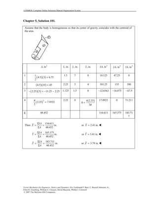
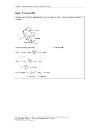
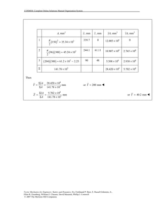
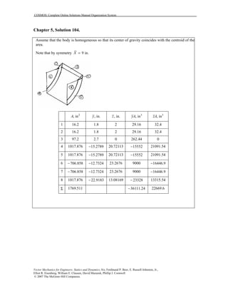
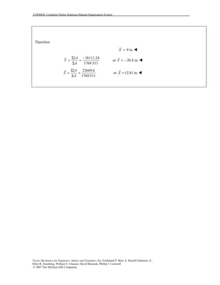
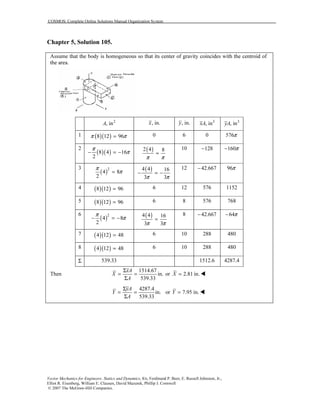
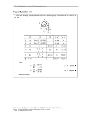
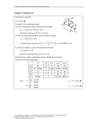
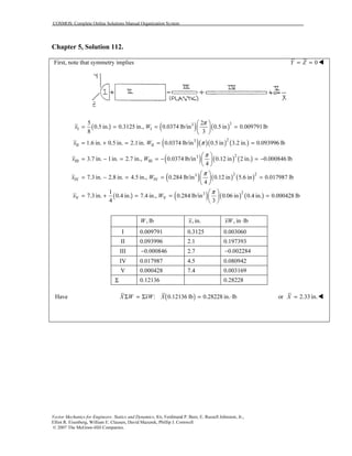
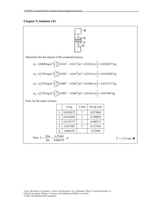
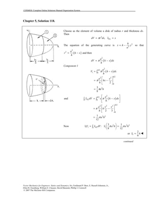
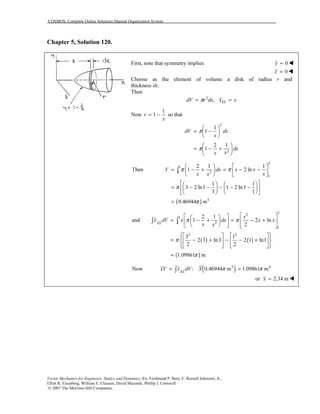
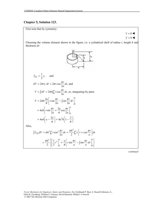
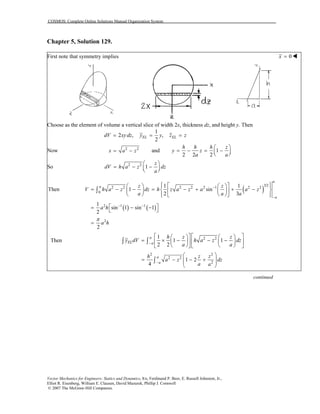
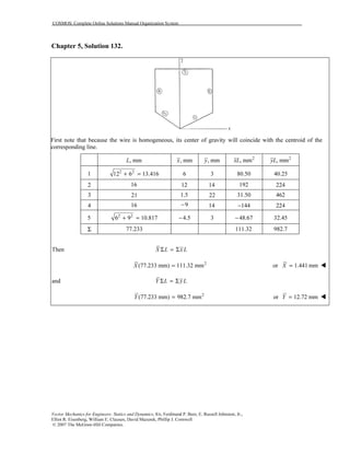
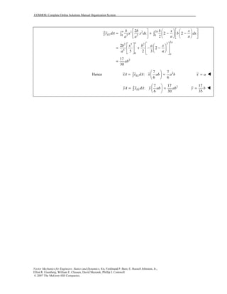
Chapter 5, Solution 42.
First note that because the wire is homogeneous, its center of gravity
coincides with the centroid of the corresponding line
Now cosELx r θ= and dL rdθ=
Then [ ]7 /47 /4
/4 /4
3
2
L dL rd r r
ππ
π π
θ θ π= = = =∫ ∫
and ( )7 /4
/4
cosELx dL r rd
π
π
θ θ=∫ ∫
[ ]7 /42 2 2
/4
1 1
sin 2
2 2
r r r
π
π
θ
= = − − = −
23
Thus : 2
2
xL xdL x r rπ
= = −
∫
2 2
3
x r
π
= −](https://image.slidesharecdn.com/cap05-151120025858-lva1-app6892/85/BEER-Cap-05-Solucionario-49-320.jpg)
![COSMOS: Complete Online Solutions Manual Organization System
Vector Mechanics for Engineers: Statics and Dynamics, 8/e, Ferdinand P. Beer, E. Russell Johnston, Jr.,
Elliot R. Eisenberg, William E. Clausen, David Mazurek, Phillip J. Cornwell
© 2007 The McGraw-Hill Companies.
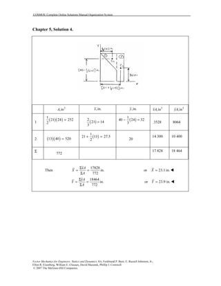
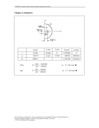
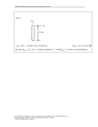
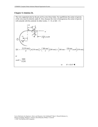
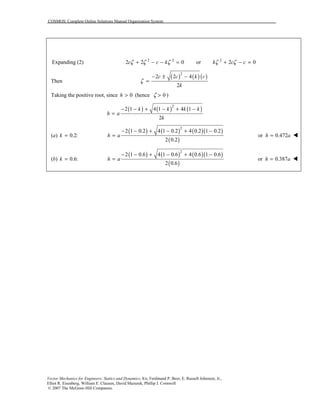
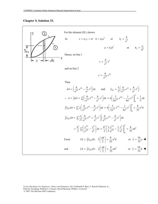
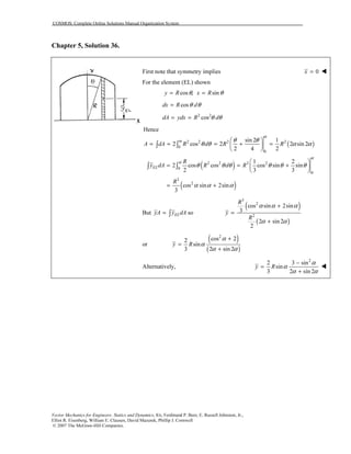
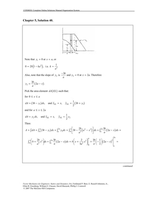
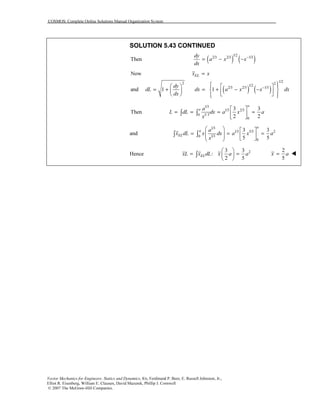
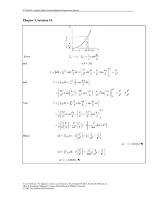
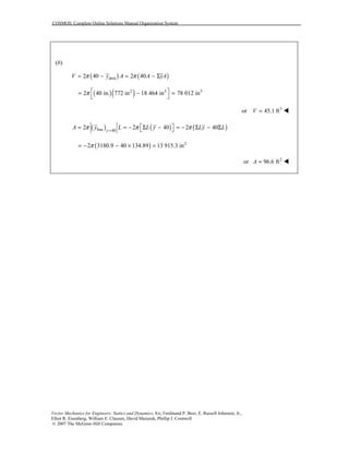
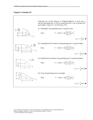
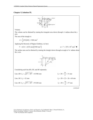
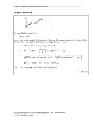
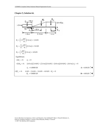
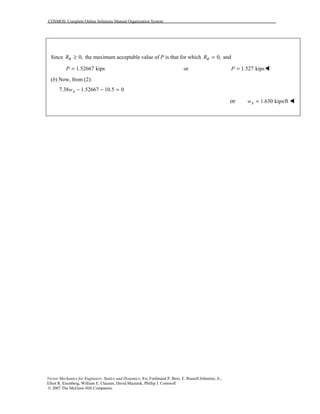
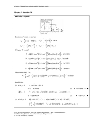
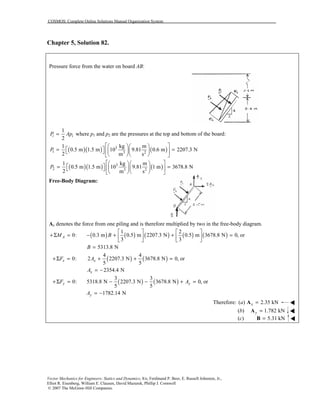
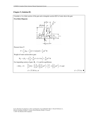
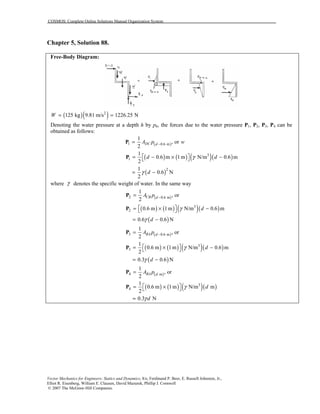
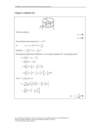
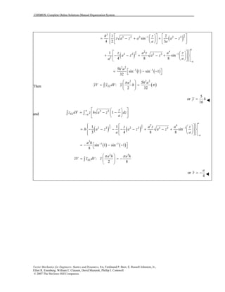
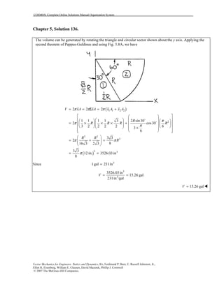
Then applying the theorems of Pappus-Guldinus for the part of the surface area generated by the
lines:
( )( ) ( )( ) ( )( ) [ ] 3 2
31 63.906 68 52 57 95.268 10947.6 34.392 10 mmLA xAπ π π = Σ = + + = = ×
The area of the “end triangles”:
( )( ) 3 21
2 52 60 3.12 10 mm
2
EA
= = ×
Total surface area is therefore:
( ) 3 2
34.392 3.12 10 mmL EA A A= + = + × 3 2
or 37.5 10 mmA = × !](https://image.slidesharecdn.com/cap05-151120025858-lva1-app6892/85/BEER-Cap-05-Solucionario-66-320.jpg)


![COSMOS: Complete Online Solutions Manual Organization System
Vector Mechanics for Engineers: Statics and Dynamics, 8/e, Ferdinand P. Beer, E. Russell Johnston, Jr.,
Elliot R. Eisenberg, William E. Clausen, David Mazurek, Phillip J. Cornwell
© 2007 The McGraw-Hill Companies.
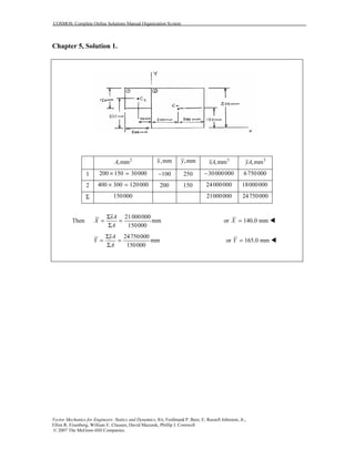
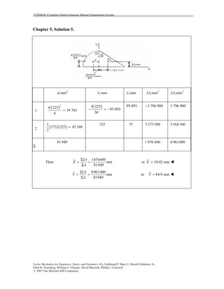
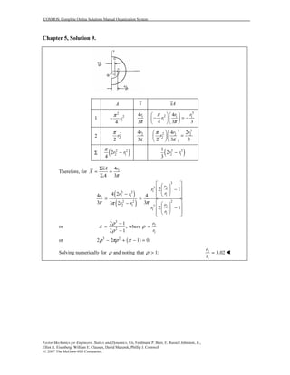
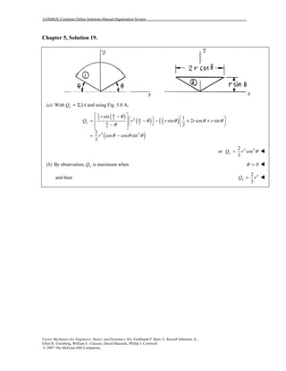
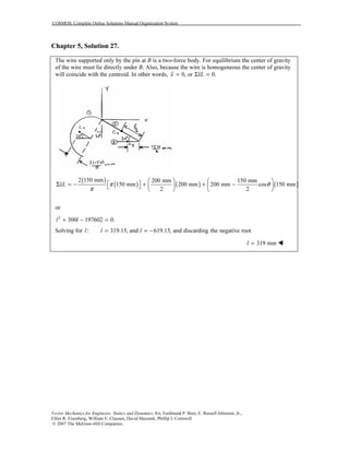
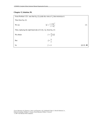
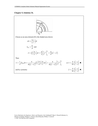
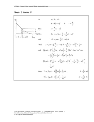
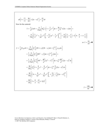
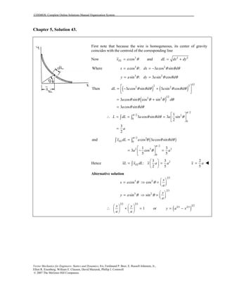
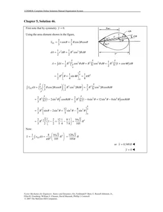
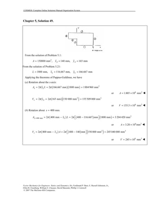
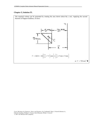
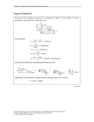
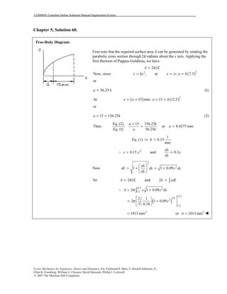
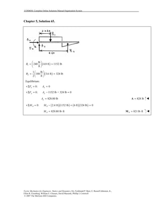
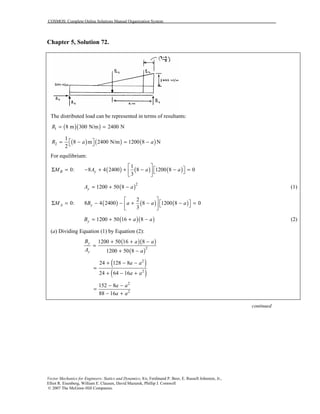
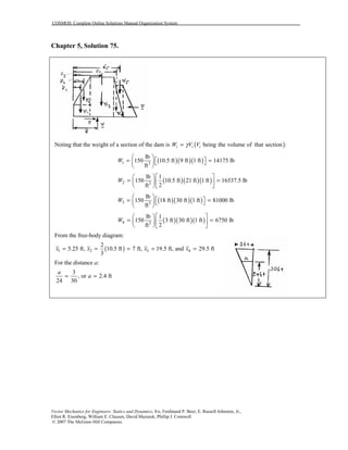
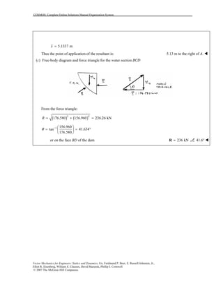
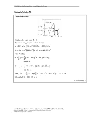
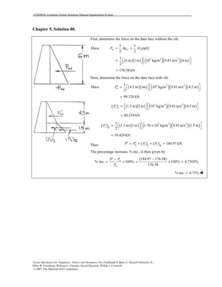
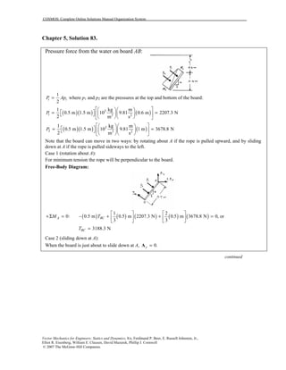
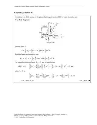
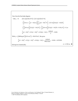
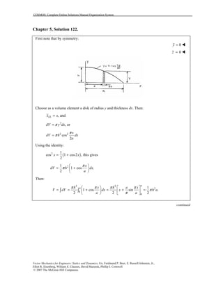
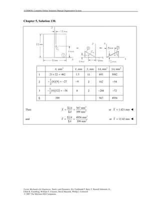
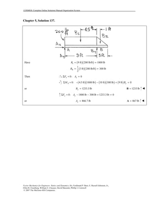
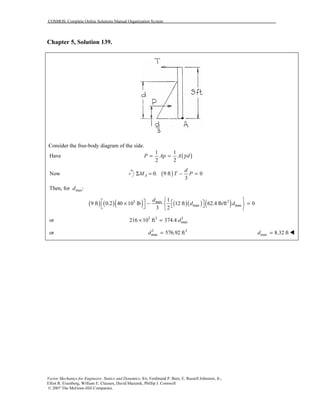
Chapter 5, Solution 79.
Since gate is 4 ft wide:
( )1 4 3p hγ= −
2 4p hγ=
( )1 4 3p dγ′ ′= −
2 4p dγ′ ′=
( )( ) ( ) ( ) ( ) ( ) ( )1 1 1 1
1 1
3 ft 3 ft 4 3 4 3 6 3 6 3
2 2
P P p p d h d hγ γ γ γ′ ′ ′ ′ − = − = − − − = − − −
( )( ) ( )[ ]2 2 2 2
1 1
3 ft 3 ft 4 4 6 6
2 2
P P p p d h d hγ γ γ γ′ ′ ′ ′− = − = − = −
This gives the free-body diagram:
( ) ( )( ) ( )( )1 1 2 20: 3 ft 1 ft 2 ft 0AM B P P P P′ ′+Σ = − − − − =
or ( ) ( )1 1 2 2
1 2
3 3
B P P P P′ ′= − − −
( ) ( ) [ ]
1 2
6 3 6 3 6 6
3 3
d h d hγ γ γ γ′ ′ = − − − − −
( ) ( )2 3 2 3 4 4d h d hγ γ γ γ′ ′= − − − + −
or ( ) ( )6 1 6 1B d hγ γ′= − − − (1)
( ) ( )1 1 2 20: 0,xF A B P P P P′ ′+Σ = + − − − − = or using (1)
( ) ( ) ( ) ( ) [ ]6 1 6 1 6 3 6 3 6 6 0,A d h d h d hγ γ γ γ γ γ′ ′ ′ + − − − − − − − − − = or
( ) ( )6 2 6 2A d hγ γ′= − − − (2)
Using the given data in (1) and (2):
3 3
6 ft, 9 ft, 62.4 lb/ft , 64 lb/fth d γ γ ′= = = =
( )( ) ( )( )6 64 9 2 6 62.4 6 2A = − − −](https://image.slidesharecdn.com/cap05-151120025858-lva1-app6892/85/BEER-Cap-05-Solucionario-97-320.jpg)
![COSMOS: Complete Online Solutions Manual Organization System
Vector Mechanics for Engineers: Statics and Dynamics, 8/e, Ferdinand P. Beer, E. Russell Johnston, Jr.,
Elliot R. Eisenberg, William E. Clausen, David Mazurek, Phillip J. Cornwell
© 2007 The McGraw-Hill Companies.
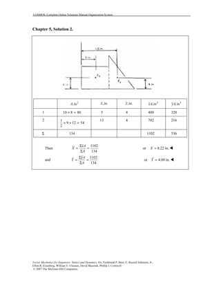
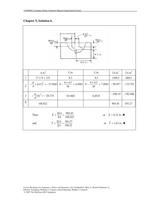
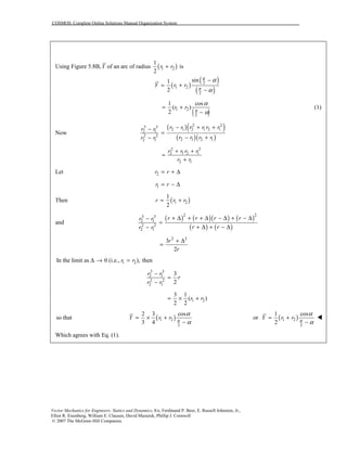
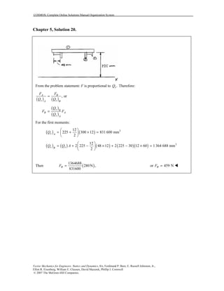
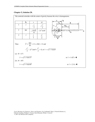
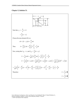
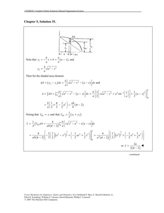
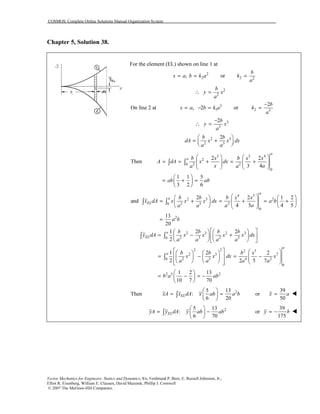
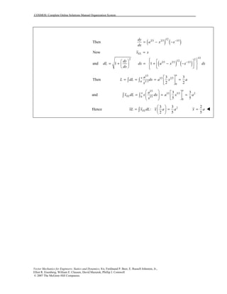
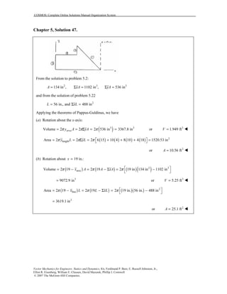
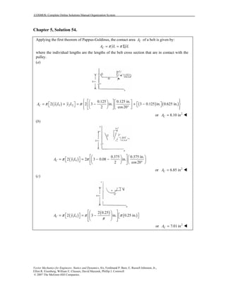
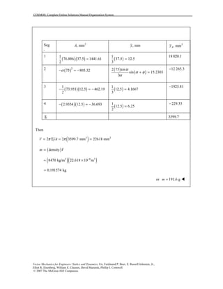
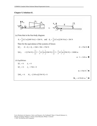
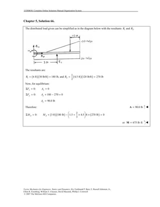
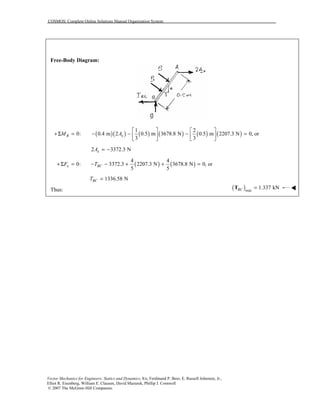
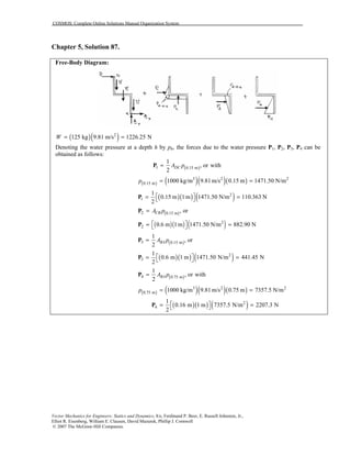
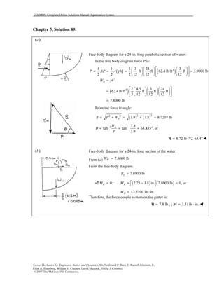
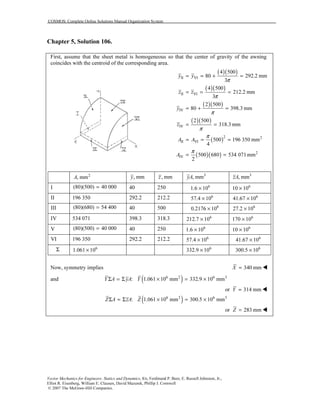
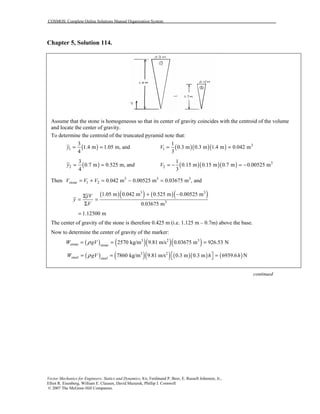
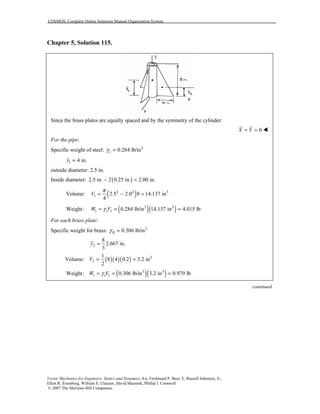
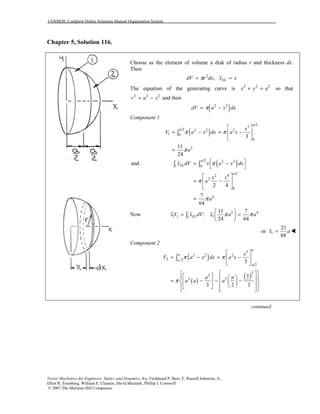
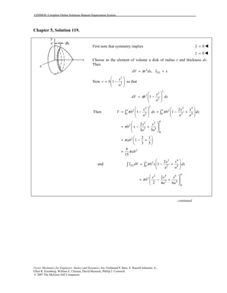
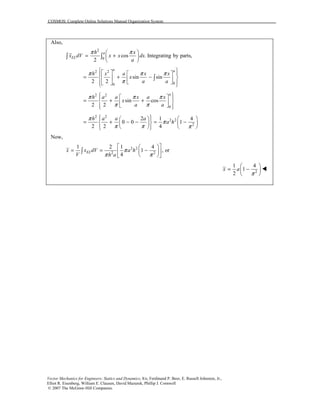
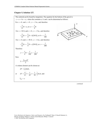
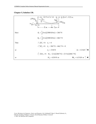
Chapter 5, Solution 125.
Since the spherical cup is uniform, the center of gravity will coincide with the centroid. Also, because the cup is
thin, it can be treated like an area in finding the centroid.
An element of area is obtained by rotating arc ds about the y axis. With the y axis pointing downwards,
( )2 2 sindA rds R Rdπ π θ θ= =
2
2 sinR dπ θ θ=
cosELy y R θ= =
[ ] ( )2 2 2
0 0
2 sin 2 cos 2 1 cosA dA R d R R
φφ
π θ θ π θ π φ= = = − = −∫ ∫
( )( )2 3
0 0
cos 2 sin 2 cos sinELy dA R R d R d
φ φ
θ π θ θ π θ θ θ= =∫ ∫ ∫
( )3 2 3 2
0
1
2 cos 1 cos
2
R R
φ
π θ π φ
= − = −
Then,
( )
( )3 2
2
1 1
1 cos , or
2 1 cos
ELy y dA R
A R
π φ
π φ
= = −
−
∫
( )1 cos
2
R
y φ= +
Using
cos 1 :
R h h
R R
φ
−
= = −
1 1
2 2
R h h
y R
R
= + − = −
The center of gravity is therefore located at a distance of
,
2 2
h h
R y R R
− = − − =
above the base.(Q.E.D)](https://image.slidesharecdn.com/cap05-151120025858-lva1-app6892/85/BEER-Cap-05-Solucionario-160-320.jpg)
![COSMOS: Complete Online Solutions Manual Organization System
Vector Mechanics for Engineers: Statics and Dynamics, 8/e, Ferdinand P. Beer, E. Russell Johnston, Jr.,
Elliot R. Eisenberg, William E. Clausen, David Mazurek, Phillip J. Cornwell
© 2007 The McGraw-Hill Companies.
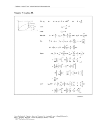
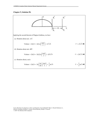
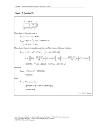
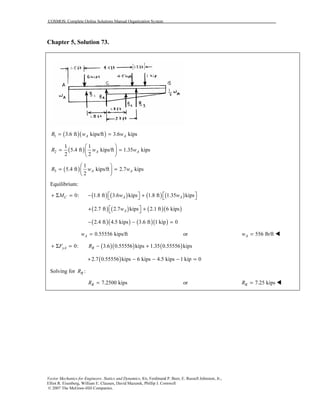
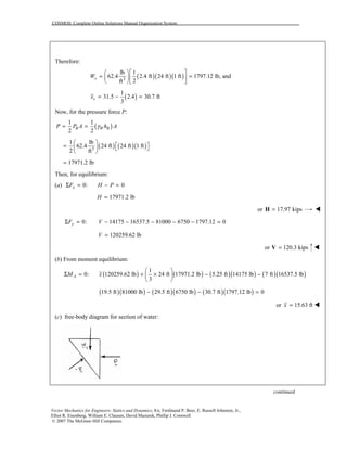
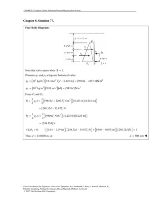
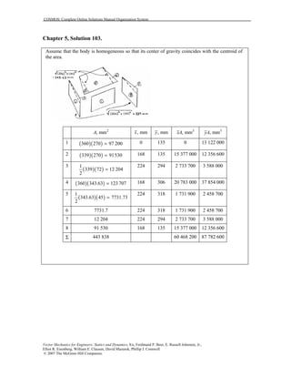
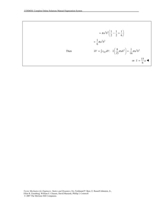
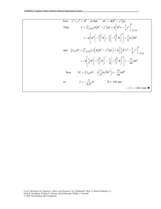
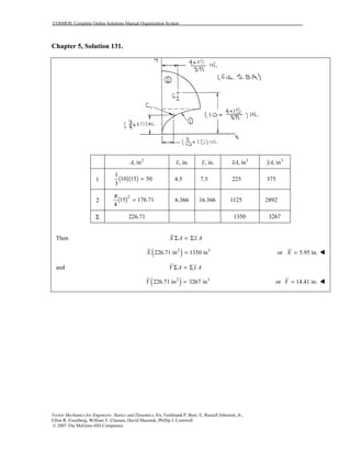
Chapter 5, Solution 126.
(a) Bowl
First note that symmetry implies 0x = !
0z = !
for the coordinate axes shown below. Now assume that the bowl may be
treated as a shell; the center of gravity of the bowl will coincide with the
centroid of the shell. For the walls of the bowl, an element of area is
obtained by rotating the arc ds about the y axis. Then
( )( )wall 2 sindA R Rdπ θ θ=
and ( )wall
cosELy R θ= −
[ ] /2/2 2 2
wall /6 /6
2
Then 2 sin 2 cos
3
A R d R
R
ππ
π π
π θ θ π θ
π
= = −
=
∫
( )
( )( )
wall wall wall
/2 2
/6
/2
3 2
/6
3
and
cos 2 sin
cos
3
4
ELy A y dA
R R d
R
R
π
π
π
π
θ π θ θ
π θ
π
=
= −
=
= −
∫
∫
2
base base
3
By observation ,
4 2
A R y R
π
= = −
Now y A yAΣ = Σ
2 2 3 23 3
or 3
4 4 4 2
y R R R R R
π π
π π
+ = − + −
or 0.48763 350 mmy R R= − =
170.7 mmy∴ = − !
(b) Punch
First note that symmetry implies 0x = !
0z = !
and that because the punch is homogeneous, its center of gravity will
coincide with the centroid of the corresponding volume. Choose as the
element of volume a disk of radius x and thickness dy. Then
2
, ELdV x dy y yπ= =
continued](https://image.slidesharecdn.com/cap05-151120025858-lva1-app6892/85/BEER-Cap-05-Solucionario-161-320.jpg)

The document contains 11 multi-part solutions to problems from Chapter 5 of the textbook "Vector Mechanics for Engineers: Statics and Dynamics, 8th edition" by Ferdinand P. Beer, E. Russell Johnston, Jr., Elliot R. Eisenberg, William E. Clausen, David Mazurek, and Phillip J. Cornwell. Each solution finds the x-coordinate or y-coordinate of the centroid of one or more areas given dimensions and coordinates of the individual areas. Formulas for the centroid of standard shapes like triangles, circles, and semicircles are used to calculate the x- and y-coordinates of the centroid for the total area.