SlideShare a Scribd company logo
1 of 20
Download to read offline
Mulugeta D. Abera 1 
 
 
2. FUNDAMENTAL OF THE THEORY OF DAMAGES
Damages are causes for the Loss of functionality and workability of production if proper action
is not taken against them. Even under optimum design and operation conditions damage is
unavoidable. Thus dames are the reasons for the existence of a maintenance organization.
To deal with maintenance on a scientific basis, it is necessary to study the reasons for and forms
of damages and the possibility for reducing the influence of damages.
2.1 CLASSIFICATION OF DAMAGES
The use-value of equipment to a means of production is affected by two processes. These are
technological processes and technical and economical processes
Fig. 1 Classification of damages
These two processes reduce the use value of means of production. Technological processes are
related t change of state of equipment which causes damages, while technical –economical
processes cause loss in the value of machinery due to obsolescence or the existence of new
equipment with higher productivity, lower costs, lower material consumption etc.
Mulugeta D. Abera 2 
 
 
2.1.1 Technical-Economical Processes
These processes are related to development in the technology of equipment which causes loss in
the use value of machinery due to obsolescence or the existence of new equipment with higher
productivity, lower costs, lower material consumption etc.
2.1.2 Technical Processes
The processes are related to change of state of equipment or means production which result from
operational processes. The changes of state are manifested in the form of damages. The focus of
this chapter is to analyze these damages.
2.2 REASONS FOR DAMAGES
Damages influenced by environmental conditions and conditions of use of equipment. For proper
maintenance work, it is necessary to make systematic analysis of damages which includes
discussions on reasons for damages and their consequences. The conclusions obtained are
feedback to designers, manufactures and operational maintenance personnel.
Reason for damages can basically be classified as follow:
a. Objective: Those are damages caused by operational processes and environmental causes.
These damages are unavoidable.
b. Subjective: These are caused by failure in design, manufacturing, use operation and
maintenance. If equipment or a means of production is handled appropriately subjective
damages can be avoided.
2.3 BEHAVIOR OF DAMAGES:
The behavior of damages as related to time under the action of damaging or operational
conditions is either sudden or continuous.
2.3.1 Sudden Behavior
In this type of behavior, the use-value of equipment diminishes instantly; in other words, sudden
breakdown of equipment takes place.
Mulugeta D. Abera 3 
 
 
2.3.2 Continuous Behavior
In such a behavior, the use value of equipment decreases with time due to wear. This is a
degradation process that comes with time under loading conditions.
Fig. 2 Use-value and load behavior
2.4 TYPICAL DAMAGES OF EQUIPMENT
The changes of state of damages as are commonly known that result from technological
processes are basically classified into three. These are: corrosion, wear and tear and fatigue.
Apart from these, the natural phenomenon of aging can also be taken as damage process. These
damages are discussed briefly below.
2.5 CORROSION
Corrosion is the destruction or deterioration of materials by chemical or electrochemical reaction
with the environment. This includes the destruction of metals in all types of atmospheres and
liquids and at any temperature. Corrosion is usually superficial but it sometimes is directed along
grain boundaries or other lines of weakness because of differences in resistance to attack or local
electrolyte action. Under most ordinary conditions of exposure corrosion products consist mainly
of oxides, carbonates and sulphides. In many environments corrosion occurs because most
metals are not inherently stable and lend themselves to revert to a more stable combination of
Mulugeta D. Abera 4 
 
 
which the metallic ores are found in nature. Corrosion reduces the useful life of equipment. And
about 5% of yearly production of steel is destroyed by corrosion.
2.5.1 The Process Corrosion
The process of corrosion takes place due to direct chemical action, when the metal enters into a
chemical reaction with other elements to form non-metallic compound or due to electrochemical
action. Metallic elements when placed in contact with water or a solution have definite inherent
tendencies to go into the solution in the form of electrically charged particles. In general, the
metal and particularly iron which enters a solution is throw down as rust. This formation of rust
affects the continuation of the corrosion process in a number of possible ways two of which are
the following.
i. Direct Chemical Corrosion:
This corrosion is limited to conditions involving highly corrosive environments or high
temperature of both. Examples are: metals left open in damp environments and high
temperature; metals in contact with strong acids or alkalis.
ii. Electrochemical Corrosion:
This characterized by movement of metallic ions I solutions. Examples: when zinc is
placed in dilute hydrochloride acid a vigorous reaction occurs, hydrogen gas is evolved
and zinc dissolves to from zinc chloride. This reaction can be divided into the anodic and
cathodic reactions. During metallic corrosion, the rate of oxidation equals the rate of
reduction.
2.5.2 Kinds of Corrosion
Corrosion is classified by the forms in which it manifests itself, the basis for this classification
being the appearance of the corroded metal, which can be identified by visual observation.
i. Surface corrosion (uniform attack)
This is the most common form of corrosion manifest over the entire exposed surface or
over a large area. This type of corrosion is caused by influence of ambient conditions on
unprotected metal surfaces. Its characteristic features are:
‐ Surface is destroyed nearly parallel to the surface and
‐ Metal becomes thinner and eventually may fail
Mulugeta D. Abera 5 
 
 
From the technical standpoint surface corrosion is not of great concern.
ii. Pitting corrosion
This is one of the most destructive and insidious forms of corrosion. It causes equipment
failure because of perforation with only a very small percent weight loss of entire
equipment. The characteristic features of pitting corrosion are:
‐ Difficult to detect because of small size of pin from which often are covered with
corrosion products
‐ Usually it results in localized destruction materials (surface) and
‐ It can take place below the surface affecting the strength of the component (invisible)
iii. Inter-crystalline corrosion
This type of corrosion takes place below the surface and occurs at the grain boundary of
metal alloys usually causing sudden crack.
iv. Trans-crystalline corrosion
As in the case of inter-crystalline corrosion, trans-crystalline corrosion also takes place
below the surface. But unlike the inter-crystalline corrosion it takes place across the
grains of metal alloys.
v. Galvanic corrosion (two-metal corrosion)
This is corrosion associated with the current of a galvanic cell made up of two dissimilar
metals. A potential difference usually exists between two dissimilar metals when they are
immersed in a corrosion solution. If these metals are placed in contact, the potential
difference produces electron flow between them and corrosion of the less corrosion
resistant metal is increased. The less resistant metal becomes anodic and the more
resistant metal cathodic causing transfer of ions, which results in galvanic corrosion.
2.5.3 Common Locations of Corrosion
Common locations where problems can be found are the following:
‐ Along the water-line in partially filled tanks
‐ In and around drops of water on steel surfaces
‐ Along crack lines
‐ Along joints, particularly in dissimilar metals
‐ Along cold-worked area like bending, sharp ends, etc.
Mulugeta D. Abera 6 
 
 
2.5.4 Factors Stimulating Corrosion
Basic factors that simulate the process of corrosion are the following:
‐ Atmospheric corrosion is simulated by damp atmosphere, since a film of water is
maintained on the surface which is an essential condition for corrosion
‐ Oxygen dissolved in water
‐ Acids, acid gases in the atmosphere, sulphur compounds, coke, coal dust etc…
‐ Salts that dissociate in water producing acid reactions
‐ Contact of dissimilar metals
‐ Cold working process on metals results in increased rate of attack by acids
‐ Fatigue stresses
‐ Rust may accelerate corrosion and cause pitting and
‐ Corrosion on metals under stress is much more severe than under ordinary conditions.
2.5.5 Methods of Minimizing Corrosion
From the point of view of maintenance damages caused by corrosion have to be dealt with
preventively. Some of the methods of minimizing of corrosion are the following.
‐ Use of a coating of protective metal such as zinc, tin, lead etc…
‐ Application of protective paints
‐ Rendering the surface of the metal passive (immersing in nitric acid after it has been
highly poised immersing in fuming sulphuric acid)
2.5.6 Corrosion Problems
Corrosion problems are pronounced to a varying degree in
‐ Steam generating plants
‐ Equipment in chemical plants
‐ Pipes and piping and
‐ Structures
Mulugeta D. Abera 7 
 
 
2.6 WEAR
The phenomenon of wear is treated under the subject matter of tribology. Tribology is the
science and technology of interacting surfaces in relative motion which embraces the general
concepts of all aspects of the transmission and dissipation of energy. Friction, wear, lubrication
come under tribology.
Wear mechanisms that are frequently encountered in practice are schematically represented in
figure 4. The figure shows the system structure interaction between the mating parts, the
tribological action, the type of wear that ensures and the effective wear mechanism that takes
place.
Wear is an undesired change of surface of machine components by the removal of little particles
caused by mechanical reasons and/or tribochemical reasons,. Mostly, wear is caused by friction
of two mating parts. For the formation of wear as a result of friction the following conditions
must be fulfilled.
‐ There must be a pair of contacting wear partners consisting of a basic body and a
mating body
‐ A normal force must act maintaining contact between the basic and mating bodies
‐ There must exist relative motion between the contacting surfaces
‐ Other factors that represent those factors that may accelerate or retard wear processes
Relative motion between the mating parts can be sliding, rolling, drilling or fretting motion. The
amount of motion, direction and time behavior affect the resulting wear
Normal force must be applied to keep the mating parts in contact. The magnitude, direction and
time behavior (static of dynamic) of the normal force affect the resulting wear
Intermediate material can be solid, liquid or gaseous. These materials are mostly used in the form
of lubricants.
Others factors that influence wear include factors like environmental conditions (temperature,
moisture, presence of attacking gases etc…) presence of contaminating materials (chips, dust,
harmful gases etc…)
2.6.1 Kinds of Wear and Tear
The whole field of wear which is diverse is divided into limited areas with similar conditions.
i. Depending on the relative motion of mating parts there are three kinds of wear
Mulugeta D. Abera 8 
 
 
a. Kinematic wear which may possess any one or a combination of the following
motion characteristics:
b. Static wear
c. Impact wear
ii. Depending on the time behavior of wear there are two kinds of wear.
a. Stationary wear in which the wears intensify remains constant over a long period of
time.
b. Non-stationary wear in which the wear intensity depends on time
2.6.2 Mechanisms of Wear
Recent investigations in wear phenomenon indicate that wear of materials occurs by many
different mechanisms depending on the materials, the environmental and operating conditions,
and the geometry of the wearing bodies. These wear mechanisms may be classified into two
groups:
‐ Those primarily dominated by the mechanical behavior of solids and
‐ Those primarily dominated by the chemical behavior of materials, other factors being
temperature and operating conditions
The chain of events that leads to the generation of wear particles and material removal from a
given tribological system is initiated by two board classes of tribological processes.
Classification of these wear mechanisms are shown in figure 3.
Mulugeta D. Abera 9 
 
 
Fig. 3, Tribological interactions and wear mechanisms
(Source: Michael J. Neale, The Tribology Handbook, 2nd
ed., Butterworth – Heinenemann Publishing, 1995)
i. Stress intersections
These are due to the combined action of load forces and frictional forces that lead to wear
processes described broadly as surface fatigue and abrasion. These wear mechanisms are
stress interactions.
a. Surface fatigue wear mechanisms: This phenomenon may occur mainly due to the
action of stresses in or below the surfaces without needing a direct physical solid
contact of the surface under consideration. Surface fatigue effects are observed to
occur in journal bearings. The effect of fatigue wear is especially associated with
repeated stress cycling in rolling contact and is accompanied by the generation and
propagation of cracks.
b. Abrasive wear mechanisms: The effect of abrasive occurs in contact situations in
which direct physical contact between two surfaces is given where one of the surfaces
is considerably harder than the other. The harder surface causes wear of the softer
material. Abrasion is usually caused either by particles which are embedded or
Mulugeta D. Abera 10 
 
 
attached to some opposing force or by particles which are free to slide and roll
between two surfaces.
ii. Materials interactions
Due to intermolecular forces either between the interacting solid bodies or between the
interacting solid bodies and the environmental atmosphere and/or the interfacial medium
and lead to wear processes described broadly as tribochemical reactions and adhesion
a. Tribochemical wear mechanisms: Surface fatigue and abrasion wear mechanisms are
described mainly in terms of stress interactions and deformation properties. But in
tribochemical wear the dynamic interactions between the material components and
the environment determine the wear process where the environment is the third
partner.
b. Adhesive wear mechanisms: Adhesive is the ability of atomic structures to hold
themselves together and form surface bonds with other atoms or surfaces with which
they come into contact. The adhesive wear processes are initated by the interfacial
adhesive junctions, which form if solid materials are in contact on an atomic scale.
Material is then transferred due to adhesive joint formation which leads to rupture.
Wear mechanisms that are frequently encountered in practice are schematically represented in
figure 4. The figure shows the system structure, interacting or mating parts, the tribological
action, and type of wear that ensures and the effective wear mechanisms that takes place.
2.6.3 Wear Process
It is a complex which is dependent on a number of factors such as load, velocity, immediate
material, and ambient conditions etc… wear processes are accompanied by heating in the micro-
range as well as changes in the physical and chemical material properties of the wear partners.
Wear processes can be differentiated into the following
i. Shearing process
Mulugeta D. Abera 11 
 
 
Roughness points will be sheared off if the acting forces are greater than the shear strength.
This leads to the reduction of roughness and increased percentage of contact area which
reduces energy concentration and wears velocity.
ii. Elastic deformation
Big surface roughness results in low percentage o contact area and high energy
concentration in contact point. This may result in high local stresses. In the elastic range
this causes small flattening or bending of roughness points. Repetition of this process will
cause local fatigue of material.
iii. Plastic deformation
If the local stress produced exceeds the elastic limit; plastic deformation takes place in
flattening and bending the material with no loss in mass.
Mulugeta D. Abera 12 
 
 
Fig. 4 Commonly encountered wear mechanisms
Mulugeta D. Abera 13 
 
 
2.6.4 Wear Types
Depending on the presence of lubricants and/or lack of it, wear types are classified into the
following.
i. Wear by solid friction
Solid friction occurs between the contacting surfaces of two bodies having relative
motion where there is no intermediate material. In relation to the surface roughness we
find wear process by shearing, plastic and elastic deformation. Wear by solid friction
results in heating of the surfaces.
ii. Wear by liquid friction
In the case of liquid friction the two mating bodies are completely separated from each
other by an intermediate material mostly lubricant. Friction occurs in the lubricant and
wear is influenced by load, relative velocity, temperature, viscosity of lubricant, the
lubricating gap and the force of inertia are neglected.
iii. Wear by mixed friction
Simultaneous action of solid and liquid friction caused by high roughness or high load for
the lubricating film causes wear by mixed friction. This results in metallic contact at
times.
2.6.5 Time behavior of wear
Amount of wear depends on time according to the equation
Where
– is exponent of wear behavior
- is amount of wear
- is wear velocity and
– is the initial wear
Depending on α assuming the initial wear = 0 the wear behavior with time can be increasing,
decreasing or constant. These three wear behaviors with time are shown in the figure below.
Mulugeta D. Abera 14 
 
 
Fig. 5 Wear behavior with time
2.6.6 Protection Against Wear:
The main protection measure against wear is lubrication of the moving parts. A lubricant is the
intermediate material between two parts with relative motion for the purpose of reducing friction
and/or wear between them. Proper lubrication with timely addition/replacement of lubricant
plays a vital role in maintaining machine accuracy and increasing its working life.
2.6.7 Classification of lubricants:
Lubricants are in the form of lubricating oil, grease and solid lubricants. The use of each one of
these depends on purpose and operational desirability.
i. Lubricating oils
Lubricating oils can be mineral and synthetic oils. In addition to preventing or minimizing wear
lubricating oils perform the following duties:
‐ Cooling by reducing friction and removing excess heat generated
‐ Protection by inhibiting corrosion processes caused by air and water
‐ Cleaning by flushing dirt particles away from lubricated surfaces
a. Mineral oils
Mineral oils are basically hydrocarbons often with some additives to introduce specific
characteristic features in the oil. Mineral oils are classified as:
Mulugeta D. Abera 15 
 
 
‐ Paraffinic: which contain significant amounts of waxy hydrocarbons with little or no
asphaltic matter
‐ Naphthenic: which contain asphaltic matter in least fraction with little or no wax
‐ Mixed base: which contain both waxy and asphaltic materials
The viscosity of mineral oils reduces with increasing temperature and increases
significantly with pressure.
Other important lubricant properties are the following
‐ Anti-wear and EP (extreme pressure) properties
‐ Oxidation resistance
‐ Anti-corrosion properties
‐ Anti-foaming properties and
‐ Demulsibility (ability to separate from water)
Lubricating oils can become unfit for further service by oxidation, thermal decomposition
and contamination. Oxidation is the process of forming oxides by some chemical process
factors that influence oxidation are:
‐ Rise in temperature: rate of oxidation doubles for about 10 C rise
‐ Access to oxygen
‐ Presence of catalysts
‐ Type of oil (compound)
‐ Top-up rate
Mineral oils are relatively stable to thermal decomposition in the absence of oxygen. But at
high temperature over 330 C oils will decompose into fragments. The effect of thermal
decomposition is to produce light hydrocarbons and carbonaceous residues which reduce
flash point and viscosity of oil and formation of hard residues which accentuate overheating.
Contamination is probability the most common reason for changing oil. Contaminants can be
one of the following or a mixture thereof.
‐ Gaseous, like air, ammonia etc…
‐ Liquid, like water, oil of another type or viscosity or both
‐ Solid, like fuel soot, road dust, wear products
Mulugeta D. Abera 16 
 
 
Additives are added to plain mineral oils to improve their properties and/or for the purpose of
imparting new properties. These additives improve the oxidation stability of oils result in
increased operating temperatures and induce higher wear prevention ability. The main types
of additives and their functions are given below.
These additives are combined with oils in various ways so as to obtain the performance
required. The mixing if done indiscriminately however may result in undesired interactions.
b. Synthetic oils
Synthetic oils are products under controlled conditions industrially from chemical base and
additives. These are pure, idealized lubricants whose molecules are uniform in weight and
shape. Synthetic oils are engineered to perform under rigorous conditions and extreme
temperature.
The most important properties of synthetic oils are the following:
Added lubricity, higher film strength, good engine start-up properties, and good resistance to
thinning, improved energy efficiency, less sludge or deposit formation, good thermal
properties, stability and good fire resisting properties.
Because of their properties, synthetic oils are used for high speed lubrication under extreme
loading conditions. However, synthetic oils have some disadvantages and these are:
‐ Compatibility problem with paints, elastomers and certain metals
‐ Reactive in the presence of water resulting in hydrolysis and corrosion
‐ High potential for toxicity
‐ Disposal problem due to degradable molecular structure
‐ More expensive
ii. Grease
It is may be defined as solid to semi-solid lubricant consisting of a dispersion of a thickening
agent in a lubricating fluid. The consistency of grease depends on the percentage of thickener in
the grease. Depending on the degree of consistency, greases are classified as.
‐Semi-fluid
‐Soft
‐Stiff
Mulugeta D. Abera 17 
 
 
This classification is based on the measure of penetration by a ball in the grease when released
from a certain height.
Types of greases are normally determined by thickener type used and these are classified as
conventional soap greases, complex soap greases or non-soap greases.
In selecting grease for use considerations must be given to conditions and nature of use. The first
thing to be decided is the consistency range. Next comes the operating temperature. Use of
greases is limited to very low speeds up to 2m/s. They find good use where sealing against dirt is
sought or for intermittent low speed motions.
Application of grease in machinery has their relative advantages and disadvantages over using
oils. Advantages of using greases include the following:
‐ Convenience: grease is easily retained where it is applied
‐ Persistence: lubricating film is retained on surface during shutdown
‐ Protection: minimum leakage thus encouraging the formation of protective coating
against corrosion
‐ Cleanliness: greases don’t leak nor splash thus maintaining cleanliness of surfaces
where they are applied
The disadvantages of using grease are the following
‐ Poor cooling properties: greases don’t dissipate heat generated easily
‐ Contamination: greases can easily get contaminated by dirt, wear debris, oxidation
products etc…
‐Low speed of application: greases cannot be applied where working speed are over 2m/s
iii. Solid lubricants
A solid lubricant is defined as any solid used as power or a thin film on a surface to provide
protection from damage relative motion so as to reduce friction and wear. Solid lubricants are
used when fluid lubricants, i.e. oils and greases are undesirable or ineffective. Fluid lubricants
are undesirable if they are liable to contaminate product as in food machinery, electrical contacts
etc. fluid lubricants are ineffective in hostile environments, high temperature, extreme pressures
and fretting conditions. A common type of solid lubricant is graphite.
The following are some properties of solid lubricants:
Mulugeta D. Abera 18 
 
 
‐Solid lubricants are incapable of carrying away heat
‐Solid lubricants are immobile and they must somehow be bonded to the surface
‐Solid lubricants are capable of retaining their lubricating effectiveness at high
temperatures
2.6.8 Lubricating Systems:
There are two methods of lubricating.
i. Non-circulating lubrication
This is a process of a single passing of a lubricant through the friction area. E.g splash
lubrication (lie-bath) for transmissions application of grease by hand, packed –type etc…
ii. Circulating lubrication
There must be a circuit of lubricant without leakage. In this case all lubricating points must
be tight. This action is a continuous circuit where the lubricant is forced to flow and the
lubricating points are continuously supplied with lubricant. In the circulation type, tank,
admission, lubricating points, re-circulation is needed.
2.6.9 Planning a Lubrication Maintenance System:
When planning a lubrication system for a plant, the following techniques for sorting the work to
be done are helpful.
a) Divide the work in terms of the frequency of lubricant application
b) Divide the work by method of application and lubricant grade
c) Consider the optimum route for the lubrication personnel
By tabulating the data in this way, simple workloads can be established. As simple model for
lubrication planning is shown in figure below.
The personnel carrying out the lubrication should report back machine defects and the planned
lubrication system can be used to initiate repair work.
Mulugeta D. Abera 19 
 
 
Fig. 6 A model of planning for systematic lubrication
2.6.10 Lubrication Instructions
Lubrication instructions should be clear and easily understandable by lubricating personnel. The
procedures involved are listed below.
i. Cleaning and lubrication of machine should be done by operator himself. In this case,
random checks have to be performed so as to eliminate negligence by operator.
ii. From the document of the machine lubricating; frequency should be set.
At the start of the shift
‐ Machine should be cleaned
‐ Moving parts like grind ways, screws, feed shafts should be lubricated
‐ Oil level should be checked
At the end of the shift
Mulugeta D. Abera 20 
 
 
‐ Machine should be cleaned off chips, dust, foreign materials
‐ Exposed pars must be lubricated to prevent rusting
Periodically
‐ Oil reservoirs, containers of oil including systems should be cleaned and filled up to
level
‐ Replacement of oil should be done. Topping up of oils should be discouraged as
much as possible
iii. Lubrication points should be marked differently for the working ease of operator.
2.7 FATIGUE
Fatigue is the failure (or reduction in strength) of a material under fluctuating stresses which are
repeated a very large number of times. Fatigue failure begins with a hair-like crack which
develops at a point of discontinuity in the material (notches, groves, fillets…). Once a small
crack develops, it propagates under load to cause failure.
Components subjected to fluctuating forces must be designed for fatigue conditions. Surface
conditions residual stresses due to metal working processes of metal-treating process, stress
concentration affect fatigue strength very much. Hence they should be considered properly at
design stage.
Fatigue strength (the endurance limit) of materials is greatly decreased by the presence of a
corroding medium.
Alternating stresses tend to cause considerable damage to any protective film formed in the
normal course of action of a corrosive medium. Continual damage to this film may be a source of
the further development of cracks which accelerate fatigue failure.

More Related Content

What's hot

Manufacturing processes 20 me33p lab manual c 20
Manufacturing processes 20 me33p lab manual c 20Manufacturing processes 20 me33p lab manual c 20
Manufacturing processes 20 me33p lab manual c 20THANMAY JS
 
Mechanical Vibrations all slides
Mechanical Vibrations all slidesMechanical Vibrations all slides
Mechanical Vibrations all slidesEbrahim Hanash
 
Unit 1 what is machine design
Unit 1 what is machine designUnit 1 what is machine design
Unit 1 what is machine designSomnath Kolgiri
 
Fluid Mechanics Chapter 6. Boundary Layer Concept
Fluid Mechanics Chapter 6. Boundary Layer ConceptFluid Mechanics Chapter 6. Boundary Layer Concept
Fluid Mechanics Chapter 6. Boundary Layer ConceptAddisu Dagne Zegeye
 
Machine element,
Machine element,Machine element,
Machine element,Raj Behra
 
Design of machine elements
Design of machine elementsDesign of machine elements
Design of machine elementsbenchmate
 
DESIGN AGAINST FLUCTUATING LOAD
DESIGN AGAINST FLUCTUATING LOADDESIGN AGAINST FLUCTUATING LOAD
DESIGN AGAINST FLUCTUATING LOADPriyank Gandhi
 
punch and die design-1.pptx
punch and die design-1.pptxpunch and die design-1.pptx
punch and die design-1.pptxAmitMittal444758
 
Module 1 introduction to kinematics of machinery
Module 1 introduction to kinematics of machineryModule 1 introduction to kinematics of machinery
Module 1 introduction to kinematics of machinerytaruian
 
Design and fabrication of working model of abrasive jet machine
Design and fabrication of working model of abrasive jet machineDesign and fabrication of working model of abrasive jet machine
Design and fabrication of working model of abrasive jet machineNirmaljit Singh
 
Kinematic diagram
Kinematic diagramKinematic diagram
Kinematic diagramphysics101
 
Chapter 1 introduction to mechanical vibration
Chapter 1 introduction to mechanical vibrationChapter 1 introduction to mechanical vibration
Chapter 1 introduction to mechanical vibrationBahr Alyafei
 
Kinematics of fluid flow & it’s application.
Kinematics of fluid flow & it’s application.Kinematics of fluid flow & it’s application.
Kinematics of fluid flow & it’s application.NIKHIL PAKWANNE
 
Lec 2 stress strain diagram (lec 2)
Lec 2 stress strain diagram (lec 2)Lec 2 stress strain diagram (lec 2)
Lec 2 stress strain diagram (lec 2)Abdul Rehman Memon
 

What's hot (20)

Manufacturing processes 20 me33p lab manual c 20
Manufacturing processes 20 me33p lab manual c 20Manufacturing processes 20 me33p lab manual c 20
Manufacturing processes 20 me33p lab manual c 20
 
Machine elements
Machine elementsMachine elements
Machine elements
 
Mechanical Vibrations all slides
Mechanical Vibrations all slidesMechanical Vibrations all slides
Mechanical Vibrations all slides
 
Unit 1 what is machine design
Unit 1 what is machine designUnit 1 what is machine design
Unit 1 what is machine design
 
Fluid Mechanics Chapter 6. Boundary Layer Concept
Fluid Mechanics Chapter 6. Boundary Layer ConceptFluid Mechanics Chapter 6. Boundary Layer Concept
Fluid Mechanics Chapter 6. Boundary Layer Concept
 
Machine element,
Machine element,Machine element,
Machine element,
 
Design of machine elements
Design of machine elementsDesign of machine elements
Design of machine elements
 
DESIGN AGAINST FLUCTUATING LOAD
DESIGN AGAINST FLUCTUATING LOADDESIGN AGAINST FLUCTUATING LOAD
DESIGN AGAINST FLUCTUATING LOAD
 
punch and die design-1.pptx
punch and die design-1.pptxpunch and die design-1.pptx
punch and die design-1.pptx
 
Eulers equation
Eulers equationEulers equation
Eulers equation
 
Module 1 introduction to kinematics of machinery
Module 1 introduction to kinematics of machineryModule 1 introduction to kinematics of machinery
Module 1 introduction to kinematics of machinery
 
Riveted joints
Riveted jointsRiveted joints
Riveted joints
 
Design and fabrication of working model of abrasive jet machine
Design and fabrication of working model of abrasive jet machineDesign and fabrication of working model of abrasive jet machine
Design and fabrication of working model of abrasive jet machine
 
Impact of jet
Impact of jetImpact of jet
Impact of jet
 
Merchant's circle
Merchant's circleMerchant's circle
Merchant's circle
 
Kinematic diagram
Kinematic diagramKinematic diagram
Kinematic diagram
 
Chapter 1 introduction to mechanical vibration
Chapter 1 introduction to mechanical vibrationChapter 1 introduction to mechanical vibration
Chapter 1 introduction to mechanical vibration
 
Kinematics of fluid flow & it’s application.
Kinematics of fluid flow & it’s application.Kinematics of fluid flow & it’s application.
Kinematics of fluid flow & it’s application.
 
Lec 2 stress strain diagram (lec 2)
Lec 2 stress strain diagram (lec 2)Lec 2 stress strain diagram (lec 2)
Lec 2 stress strain diagram (lec 2)
 
Endurance limit
Endurance limitEndurance limit
Endurance limit
 

Viewers also liked

Chapter 1 (introduction)
Chapter 1 (introduction)Chapter 1 (introduction)
Chapter 1 (introduction)Mulugeta Abera
 
FINAL REPORT - Copy
FINAL REPORT - CopyFINAL REPORT - Copy
FINAL REPORT - CopyDivay Chadha
 
Final Project_ Design and FEM Analysis of Scissor Jack
Final Project_ Design and FEM Analysis of Scissor JackFinal Project_ Design and FEM Analysis of Scissor Jack
Final Project_ Design and FEM Analysis of Scissor JackMehmet Bariskan
 
DESIGN AND FABRICATION OF A POWER SCISSOR JACK
DESIGN AND FABRICATION OF A POWER SCISSOR JACKDESIGN AND FABRICATION OF A POWER SCISSOR JACK
DESIGN AND FABRICATION OF A POWER SCISSOR JACKsasank babu
 
Chapter 6 design of irrigation channel1
Chapter 6 design of irrigation channel1Chapter 6 design of irrigation channel1
Chapter 6 design of irrigation channel1Mulugeta Abera
 
What Makes Great Infographics
What Makes Great InfographicsWhat Makes Great Infographics
What Makes Great InfographicsSlideShare
 
Masters of SlideShare
Masters of SlideShareMasters of SlideShare
Masters of SlideShareKapost
 
STOP! VIEW THIS! 10-Step Checklist When Uploading to Slideshare
STOP! VIEW THIS! 10-Step Checklist When Uploading to SlideshareSTOP! VIEW THIS! 10-Step Checklist When Uploading to Slideshare
STOP! VIEW THIS! 10-Step Checklist When Uploading to SlideshareEmpowered Presentations
 
10 Ways to Win at SlideShare SEO & Presentation Optimization
10 Ways to Win at SlideShare SEO & Presentation Optimization10 Ways to Win at SlideShare SEO & Presentation Optimization
10 Ways to Win at SlideShare SEO & Presentation OptimizationOneupweb
 
How To Get More From SlideShare - Super-Simple Tips For Content Marketing
How To Get More From SlideShare - Super-Simple Tips For Content MarketingHow To Get More From SlideShare - Super-Simple Tips For Content Marketing
How To Get More From SlideShare - Super-Simple Tips For Content MarketingContent Marketing Institute
 
A Guide to SlideShare Analytics - Excerpts from Hubspot's Step by Step Guide ...
A Guide to SlideShare Analytics - Excerpts from Hubspot's Step by Step Guide ...A Guide to SlideShare Analytics - Excerpts from Hubspot's Step by Step Guide ...
A Guide to SlideShare Analytics - Excerpts from Hubspot's Step by Step Guide ...SlideShare
 
2015 Upload Campaigns Calendar - SlideShare
2015 Upload Campaigns Calendar - SlideShare2015 Upload Campaigns Calendar - SlideShare
2015 Upload Campaigns Calendar - SlideShareSlideShare
 
What to Upload to SlideShare
What to Upload to SlideShareWhat to Upload to SlideShare
What to Upload to SlideShareSlideShare
 
How to Make Awesome SlideShares: Tips & Tricks
How to Make Awesome SlideShares: Tips & TricksHow to Make Awesome SlideShares: Tips & Tricks
How to Make Awesome SlideShares: Tips & TricksSlideShare
 
Getting Started With SlideShare
Getting Started With SlideShareGetting Started With SlideShare
Getting Started With SlideShareSlideShare
 

Viewers also liked (16)

Chapter 1 (introduction)
Chapter 1 (introduction)Chapter 1 (introduction)
Chapter 1 (introduction)
 
FINAL REPORT - Copy
FINAL REPORT - CopyFINAL REPORT - Copy
FINAL REPORT - Copy
 
Final Project_ Design and FEM Analysis of Scissor Jack
Final Project_ Design and FEM Analysis of Scissor JackFinal Project_ Design and FEM Analysis of Scissor Jack
Final Project_ Design and FEM Analysis of Scissor Jack
 
DESIGN AND FABRICATION OF A POWER SCISSOR JACK
DESIGN AND FABRICATION OF A POWER SCISSOR JACKDESIGN AND FABRICATION OF A POWER SCISSOR JACK
DESIGN AND FABRICATION OF A POWER SCISSOR JACK
 
Chapter 6 design of irrigation channel1
Chapter 6 design of irrigation channel1Chapter 6 design of irrigation channel1
Chapter 6 design of irrigation channel1
 
What Makes Great Infographics
What Makes Great InfographicsWhat Makes Great Infographics
What Makes Great Infographics
 
Masters of SlideShare
Masters of SlideShareMasters of SlideShare
Masters of SlideShare
 
STOP! VIEW THIS! 10-Step Checklist When Uploading to Slideshare
STOP! VIEW THIS! 10-Step Checklist When Uploading to SlideshareSTOP! VIEW THIS! 10-Step Checklist When Uploading to Slideshare
STOP! VIEW THIS! 10-Step Checklist When Uploading to Slideshare
 
You Suck At PowerPoint!
You Suck At PowerPoint!You Suck At PowerPoint!
You Suck At PowerPoint!
 
10 Ways to Win at SlideShare SEO & Presentation Optimization
10 Ways to Win at SlideShare SEO & Presentation Optimization10 Ways to Win at SlideShare SEO & Presentation Optimization
10 Ways to Win at SlideShare SEO & Presentation Optimization
 
How To Get More From SlideShare - Super-Simple Tips For Content Marketing
How To Get More From SlideShare - Super-Simple Tips For Content MarketingHow To Get More From SlideShare - Super-Simple Tips For Content Marketing
How To Get More From SlideShare - Super-Simple Tips For Content Marketing
 
A Guide to SlideShare Analytics - Excerpts from Hubspot's Step by Step Guide ...
A Guide to SlideShare Analytics - Excerpts from Hubspot's Step by Step Guide ...A Guide to SlideShare Analytics - Excerpts from Hubspot's Step by Step Guide ...
A Guide to SlideShare Analytics - Excerpts from Hubspot's Step by Step Guide ...
 
2015 Upload Campaigns Calendar - SlideShare
2015 Upload Campaigns Calendar - SlideShare2015 Upload Campaigns Calendar - SlideShare
2015 Upload Campaigns Calendar - SlideShare
 
What to Upload to SlideShare
What to Upload to SlideShareWhat to Upload to SlideShare
What to Upload to SlideShare
 
How to Make Awesome SlideShares: Tips & Tricks
How to Make Awesome SlideShares: Tips & TricksHow to Make Awesome SlideShares: Tips & Tricks
How to Make Awesome SlideShares: Tips & Tricks
 
Getting Started With SlideShare
Getting Started With SlideShareGetting Started With SlideShare
Getting Started With SlideShare
 

Similar to Chapter two new

IRJET-Review of Marine Environmental Corrosion and Application of an Anti-Cor...
IRJET-Review of Marine Environmental Corrosion and Application of an Anti-Cor...IRJET-Review of Marine Environmental Corrosion and Application of an Anti-Cor...
IRJET-Review of Marine Environmental Corrosion and Application of an Anti-Cor...IRJET Journal
 
IRJET- Corrosion Analysis by Acid Concentration in Oil and Gas Pipelines
IRJET- Corrosion Analysis by Acid Concentration in Oil and Gas PipelinesIRJET- Corrosion Analysis by Acid Concentration in Oil and Gas Pipelines
IRJET- Corrosion Analysis by Acid Concentration in Oil and Gas PipelinesIRJET Journal
 
Sm aqueous-corrosion-book
Sm aqueous-corrosion-bookSm aqueous-corrosion-book
Sm aqueous-corrosion-bookReza Kiarasi
 
Corrosion control of underwater piles
Corrosion control of underwater pilesCorrosion control of underwater piles
Corrosion control of underwater pilesAglaia Connect
 
Corosion of engineering matrial
Corosion of engineering matrial Corosion of engineering matrial
Corosion of engineering matrial Mr.pradip Waghmare
 
Metallurgical_Factors_Affecting_Corrosio.pdf
Metallurgical_Factors_Affecting_Corrosio.pdfMetallurgical_Factors_Affecting_Corrosio.pdf
Metallurgical_Factors_Affecting_Corrosio.pdfdaifmostafa
 
Environmentally assisted failures in metallic and composite materials
Environmentally assisted failures in metallic and composite materials Environmentally assisted failures in metallic and composite materials
Environmentally assisted failures in metallic and composite materials Padmanabhan Krishnan
 
Hitesh cathodic protection
Hitesh cathodic protectionHitesh cathodic protection
Hitesh cathodic protectionHitesh Mahajan
 
Types of corrosions
Types of corrosionsTypes of corrosions
Types of corrosionsAmar Ilindra
 
Basics of corrosion_control
Basics of corrosion_controlBasics of corrosion_control
Basics of corrosion_controlAhmed Hussein
 
Introduction to Industrial Corrosion
Introduction to Industrial Corrosion Introduction to Industrial Corrosion
Introduction to Industrial Corrosion Yasir Mahdi
 
Corrosion Effect in ARP
Corrosion Effect in ARPCorrosion Effect in ARP
Corrosion Effect in ARPAjeet Kumar
 
Corrosion
CorrosionCorrosion
CorrosionRhiza
 
APPLICATION OF WASTE NATURAL MATERIAL FOR CORROSION INHIBITION OF LOW CARBON ...
APPLICATION OF WASTE NATURAL MATERIAL FOR CORROSION INHIBITION OF LOW CARBON ...APPLICATION OF WASTE NATURAL MATERIAL FOR CORROSION INHIBITION OF LOW CARBON ...
APPLICATION OF WASTE NATURAL MATERIAL FOR CORROSION INHIBITION OF LOW CARBON ...IRJET Journal
 
Forms of corrosion
Forms of corrosionForms of corrosion
Forms of corrosionchemnidhi
 
Control of corrosion on underwater piles
Control of corrosion on underwater piles Control of corrosion on underwater piles
Control of corrosion on underwater piles SELVA MANI
 
4_5992268715599596690.pptghjkjhjuuuijjjj
4_5992268715599596690.pptghjkjhjuuuijjjj4_5992268715599596690.pptghjkjhjuuuijjjj
4_5992268715599596690.pptghjkjhjuuuijjjjteddiyfentaw
 

Similar to Chapter two new (20)

IRJET-Review of Marine Environmental Corrosion and Application of an Anti-Cor...
IRJET-Review of Marine Environmental Corrosion and Application of an Anti-Cor...IRJET-Review of Marine Environmental Corrosion and Application of an Anti-Cor...
IRJET-Review of Marine Environmental Corrosion and Application of an Anti-Cor...
 
IRJET- Corrosion Analysis by Acid Concentration in Oil and Gas Pipelines
IRJET- Corrosion Analysis by Acid Concentration in Oil and Gas PipelinesIRJET- Corrosion Analysis by Acid Concentration in Oil and Gas Pipelines
IRJET- Corrosion Analysis by Acid Concentration in Oil and Gas Pipelines
 
Sm aqueous-corrosion-book
Sm aqueous-corrosion-bookSm aqueous-corrosion-book
Sm aqueous-corrosion-book
 
Corrosion control of underwater piles
Corrosion control of underwater pilesCorrosion control of underwater piles
Corrosion control of underwater piles
 
Corosion of engineering matrial
Corosion of engineering matrial Corosion of engineering matrial
Corosion of engineering matrial
 
Metallurgical_Factors_Affecting_Corrosio.pdf
Metallurgical_Factors_Affecting_Corrosio.pdfMetallurgical_Factors_Affecting_Corrosio.pdf
Metallurgical_Factors_Affecting_Corrosio.pdf
 
Environmentally assisted failures in metallic and composite materials
Environmentally assisted failures in metallic and composite materials Environmentally assisted failures in metallic and composite materials
Environmentally assisted failures in metallic and composite materials
 
Hitesh cathodic protection
Hitesh cathodic protectionHitesh cathodic protection
Hitesh cathodic protection
 
Corrosion.pdf
Corrosion.pdfCorrosion.pdf
Corrosion.pdf
 
Types of corrosions
Types of corrosionsTypes of corrosions
Types of corrosions
 
Corrosion and its preventive measures
Corrosion and its preventive measuresCorrosion and its preventive measures
Corrosion and its preventive measures
 
Basics of corrosion_control
Basics of corrosion_controlBasics of corrosion_control
Basics of corrosion_control
 
Introduction to Industrial Corrosion
Introduction to Industrial Corrosion Introduction to Industrial Corrosion
Introduction to Industrial Corrosion
 
Corrosion Effect in ARP
Corrosion Effect in ARPCorrosion Effect in ARP
Corrosion Effect in ARP
 
Nehal
NehalNehal
Nehal
 
Corrosion
CorrosionCorrosion
Corrosion
 
APPLICATION OF WASTE NATURAL MATERIAL FOR CORROSION INHIBITION OF LOW CARBON ...
APPLICATION OF WASTE NATURAL MATERIAL FOR CORROSION INHIBITION OF LOW CARBON ...APPLICATION OF WASTE NATURAL MATERIAL FOR CORROSION INHIBITION OF LOW CARBON ...
APPLICATION OF WASTE NATURAL MATERIAL FOR CORROSION INHIBITION OF LOW CARBON ...
 
Forms of corrosion
Forms of corrosionForms of corrosion
Forms of corrosion
 
Control of corrosion on underwater piles
Control of corrosion on underwater piles Control of corrosion on underwater piles
Control of corrosion on underwater piles
 
4_5992268715599596690.pptghjkjhjuuuijjjj
4_5992268715599596690.pptghjkjhjuuuijjjj4_5992268715599596690.pptghjkjhjuuuijjjj
4_5992268715599596690.pptghjkjhjuuuijjjj
 

Recently uploaded

Call Girls Service Nashik Vaishnavi 7001305949 Independent Escort Service Nashik
Call Girls Service Nashik Vaishnavi 7001305949 Independent Escort Service NashikCall Girls Service Nashik Vaishnavi 7001305949 Independent Escort Service Nashik
Call Girls Service Nashik Vaishnavi 7001305949 Independent Escort Service NashikCall Girls in Nagpur High Profile
 
Structural Analysis and Design of Foundations: A Comprehensive Handbook for S...
Structural Analysis and Design of Foundations: A Comprehensive Handbook for S...Structural Analysis and Design of Foundations: A Comprehensive Handbook for S...
Structural Analysis and Design of Foundations: A Comprehensive Handbook for S...Dr.Costas Sachpazis
 
MANUFACTURING PROCESS-II UNIT-5 NC MACHINE TOOLS
MANUFACTURING PROCESS-II UNIT-5 NC MACHINE TOOLSMANUFACTURING PROCESS-II UNIT-5 NC MACHINE TOOLS
MANUFACTURING PROCESS-II UNIT-5 NC MACHINE TOOLSSIVASHANKAR N
 
Introduction to Multiple Access Protocol.pptx
Introduction to Multiple Access Protocol.pptxIntroduction to Multiple Access Protocol.pptx
Introduction to Multiple Access Protocol.pptxupamatechverse
 
Microscopic Analysis of Ceramic Materials.pptx
Microscopic Analysis of Ceramic Materials.pptxMicroscopic Analysis of Ceramic Materials.pptx
Microscopic Analysis of Ceramic Materials.pptxpurnimasatapathy1234
 
Porous Ceramics seminar and technical writing
Porous Ceramics seminar and technical writingPorous Ceramics seminar and technical writing
Porous Ceramics seminar and technical writingrakeshbaidya232001
 
Processing & Properties of Floor and Wall Tiles.pptx
Processing & Properties of Floor and Wall Tiles.pptxProcessing & Properties of Floor and Wall Tiles.pptx
Processing & Properties of Floor and Wall Tiles.pptxpranjaldaimarysona
 
Call Girls in Nagpur Suman Call 7001035870 Meet With Nagpur Escorts
Call Girls in Nagpur Suman Call 7001035870 Meet With Nagpur EscortsCall Girls in Nagpur Suman Call 7001035870 Meet With Nagpur Escorts
Call Girls in Nagpur Suman Call 7001035870 Meet With Nagpur EscortsCall Girls in Nagpur High Profile
 
Call Girls Service Nagpur Tanvi Call 7001035870 Meet With Nagpur Escorts
Call Girls Service Nagpur Tanvi Call 7001035870 Meet With Nagpur EscortsCall Girls Service Nagpur Tanvi Call 7001035870 Meet With Nagpur Escorts
Call Girls Service Nagpur Tanvi Call 7001035870 Meet With Nagpur EscortsCall Girls in Nagpur High Profile
 
UNIT-II FMM-Flow Through Circular Conduits
UNIT-II FMM-Flow Through Circular ConduitsUNIT-II FMM-Flow Through Circular Conduits
UNIT-II FMM-Flow Through Circular Conduitsrknatarajan
 
College Call Girls Nashik Nehal 7001305949 Independent Escort Service Nashik
College Call Girls Nashik Nehal 7001305949 Independent Escort Service NashikCollege Call Girls Nashik Nehal 7001305949 Independent Escort Service Nashik
College Call Girls Nashik Nehal 7001305949 Independent Escort Service NashikCall Girls in Nagpur High Profile
 
UNIT-III FMM. DIMENSIONAL ANALYSIS
UNIT-III FMM.        DIMENSIONAL ANALYSISUNIT-III FMM.        DIMENSIONAL ANALYSIS
UNIT-III FMM. DIMENSIONAL ANALYSISrknatarajan
 
SPICE PARK APR2024 ( 6,793 SPICE Models )
SPICE PARK APR2024 ( 6,793 SPICE Models )SPICE PARK APR2024 ( 6,793 SPICE Models )
SPICE PARK APR2024 ( 6,793 SPICE Models )Tsuyoshi Horigome
 
Software Development Life Cycle By Team Orange (Dept. of Pharmacy)
Software Development Life Cycle By  Team Orange (Dept. of Pharmacy)Software Development Life Cycle By  Team Orange (Dept. of Pharmacy)
Software Development Life Cycle By Team Orange (Dept. of Pharmacy)Suman Mia
 
UNIT - IV - Air Compressors and its Performance
UNIT - IV - Air Compressors and its PerformanceUNIT - IV - Air Compressors and its Performance
UNIT - IV - Air Compressors and its Performancesivaprakash250
 
(ANVI) Koregaon Park Call Girls Just Call 7001035870 [ Cash on Delivery ] Pun...
(ANVI) Koregaon Park Call Girls Just Call 7001035870 [ Cash on Delivery ] Pun...(ANVI) Koregaon Park Call Girls Just Call 7001035870 [ Cash on Delivery ] Pun...
(ANVI) Koregaon Park Call Girls Just Call 7001035870 [ Cash on Delivery ] Pun...ranjana rawat
 
The Most Attractive Pune Call Girls Budhwar Peth 8250192130 Will You Miss Thi...
The Most Attractive Pune Call Girls Budhwar Peth 8250192130 Will You Miss Thi...The Most Attractive Pune Call Girls Budhwar Peth 8250192130 Will You Miss Thi...
The Most Attractive Pune Call Girls Budhwar Peth 8250192130 Will You Miss Thi...ranjana rawat
 
AKTU Computer Networks notes --- Unit 3.pdf
AKTU Computer Networks notes ---  Unit 3.pdfAKTU Computer Networks notes ---  Unit 3.pdf
AKTU Computer Networks notes --- Unit 3.pdfankushspencer015
 
(PRIYA) Rajgurunagar Call Girls Just Call 7001035870 [ Cash on Delivery ] Pun...
(PRIYA) Rajgurunagar Call Girls Just Call 7001035870 [ Cash on Delivery ] Pun...(PRIYA) Rajgurunagar Call Girls Just Call 7001035870 [ Cash on Delivery ] Pun...
(PRIYA) Rajgurunagar Call Girls Just Call 7001035870 [ Cash on Delivery ] Pun...ranjana rawat
 

Recently uploaded (20)

Call Girls Service Nashik Vaishnavi 7001305949 Independent Escort Service Nashik
Call Girls Service Nashik Vaishnavi 7001305949 Independent Escort Service NashikCall Girls Service Nashik Vaishnavi 7001305949 Independent Escort Service Nashik
Call Girls Service Nashik Vaishnavi 7001305949 Independent Escort Service Nashik
 
Structural Analysis and Design of Foundations: A Comprehensive Handbook for S...
Structural Analysis and Design of Foundations: A Comprehensive Handbook for S...Structural Analysis and Design of Foundations: A Comprehensive Handbook for S...
Structural Analysis and Design of Foundations: A Comprehensive Handbook for S...
 
MANUFACTURING PROCESS-II UNIT-5 NC MACHINE TOOLS
MANUFACTURING PROCESS-II UNIT-5 NC MACHINE TOOLSMANUFACTURING PROCESS-II UNIT-5 NC MACHINE TOOLS
MANUFACTURING PROCESS-II UNIT-5 NC MACHINE TOOLS
 
Introduction to Multiple Access Protocol.pptx
Introduction to Multiple Access Protocol.pptxIntroduction to Multiple Access Protocol.pptx
Introduction to Multiple Access Protocol.pptx
 
Microscopic Analysis of Ceramic Materials.pptx
Microscopic Analysis of Ceramic Materials.pptxMicroscopic Analysis of Ceramic Materials.pptx
Microscopic Analysis of Ceramic Materials.pptx
 
Porous Ceramics seminar and technical writing
Porous Ceramics seminar and technical writingPorous Ceramics seminar and technical writing
Porous Ceramics seminar and technical writing
 
Processing & Properties of Floor and Wall Tiles.pptx
Processing & Properties of Floor and Wall Tiles.pptxProcessing & Properties of Floor and Wall Tiles.pptx
Processing & Properties of Floor and Wall Tiles.pptx
 
Call Girls in Nagpur Suman Call 7001035870 Meet With Nagpur Escorts
Call Girls in Nagpur Suman Call 7001035870 Meet With Nagpur EscortsCall Girls in Nagpur Suman Call 7001035870 Meet With Nagpur Escorts
Call Girls in Nagpur Suman Call 7001035870 Meet With Nagpur Escorts
 
Call Girls Service Nagpur Tanvi Call 7001035870 Meet With Nagpur Escorts
Call Girls Service Nagpur Tanvi Call 7001035870 Meet With Nagpur EscortsCall Girls Service Nagpur Tanvi Call 7001035870 Meet With Nagpur Escorts
Call Girls Service Nagpur Tanvi Call 7001035870 Meet With Nagpur Escorts
 
UNIT-II FMM-Flow Through Circular Conduits
UNIT-II FMM-Flow Through Circular ConduitsUNIT-II FMM-Flow Through Circular Conduits
UNIT-II FMM-Flow Through Circular Conduits
 
College Call Girls Nashik Nehal 7001305949 Independent Escort Service Nashik
College Call Girls Nashik Nehal 7001305949 Independent Escort Service NashikCollege Call Girls Nashik Nehal 7001305949 Independent Escort Service Nashik
College Call Girls Nashik Nehal 7001305949 Independent Escort Service Nashik
 
Water Industry Process Automation & Control Monthly - April 2024
Water Industry Process Automation & Control Monthly - April 2024Water Industry Process Automation & Control Monthly - April 2024
Water Industry Process Automation & Control Monthly - April 2024
 
UNIT-III FMM. DIMENSIONAL ANALYSIS
UNIT-III FMM.        DIMENSIONAL ANALYSISUNIT-III FMM.        DIMENSIONAL ANALYSIS
UNIT-III FMM. DIMENSIONAL ANALYSIS
 
SPICE PARK APR2024 ( 6,793 SPICE Models )
SPICE PARK APR2024 ( 6,793 SPICE Models )SPICE PARK APR2024 ( 6,793 SPICE Models )
SPICE PARK APR2024 ( 6,793 SPICE Models )
 
Software Development Life Cycle By Team Orange (Dept. of Pharmacy)
Software Development Life Cycle By  Team Orange (Dept. of Pharmacy)Software Development Life Cycle By  Team Orange (Dept. of Pharmacy)
Software Development Life Cycle By Team Orange (Dept. of Pharmacy)
 
UNIT - IV - Air Compressors and its Performance
UNIT - IV - Air Compressors and its PerformanceUNIT - IV - Air Compressors and its Performance
UNIT - IV - Air Compressors and its Performance
 
(ANVI) Koregaon Park Call Girls Just Call 7001035870 [ Cash on Delivery ] Pun...
(ANVI) Koregaon Park Call Girls Just Call 7001035870 [ Cash on Delivery ] Pun...(ANVI) Koregaon Park Call Girls Just Call 7001035870 [ Cash on Delivery ] Pun...
(ANVI) Koregaon Park Call Girls Just Call 7001035870 [ Cash on Delivery ] Pun...
 
The Most Attractive Pune Call Girls Budhwar Peth 8250192130 Will You Miss Thi...
The Most Attractive Pune Call Girls Budhwar Peth 8250192130 Will You Miss Thi...The Most Attractive Pune Call Girls Budhwar Peth 8250192130 Will You Miss Thi...
The Most Attractive Pune Call Girls Budhwar Peth 8250192130 Will You Miss Thi...
 
AKTU Computer Networks notes --- Unit 3.pdf
AKTU Computer Networks notes ---  Unit 3.pdfAKTU Computer Networks notes ---  Unit 3.pdf
AKTU Computer Networks notes --- Unit 3.pdf
 
(PRIYA) Rajgurunagar Call Girls Just Call 7001035870 [ Cash on Delivery ] Pun...
(PRIYA) Rajgurunagar Call Girls Just Call 7001035870 [ Cash on Delivery ] Pun...(PRIYA) Rajgurunagar Call Girls Just Call 7001035870 [ Cash on Delivery ] Pun...
(PRIYA) Rajgurunagar Call Girls Just Call 7001035870 [ Cash on Delivery ] Pun...
 

Chapter two new

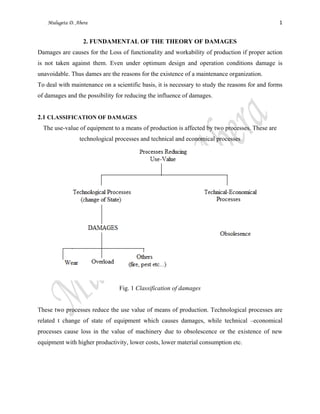
  • 1. Mulugeta D. Abera 1      2. FUNDAMENTAL OF THE THEORY OF DAMAGES Damages are causes for the Loss of functionality and workability of production if proper action is not taken against them. Even under optimum design and operation conditions damage is unavoidable. Thus dames are the reasons for the existence of a maintenance organization. To deal with maintenance on a scientific basis, it is necessary to study the reasons for and forms of damages and the possibility for reducing the influence of damages. 2.1 CLASSIFICATION OF DAMAGES The use-value of equipment to a means of production is affected by two processes. These are technological processes and technical and economical processes Fig. 1 Classification of damages These two processes reduce the use value of means of production. Technological processes are related t change of state of equipment which causes damages, while technical –economical processes cause loss in the value of machinery due to obsolescence or the existence of new equipment with higher productivity, lower costs, lower material consumption etc.
  • 2. Mulugeta D. Abera 2      2.1.1 Technical-Economical Processes These processes are related to development in the technology of equipment which causes loss in the use value of machinery due to obsolescence or the existence of new equipment with higher productivity, lower costs, lower material consumption etc. 2.1.2 Technical Processes The processes are related to change of state of equipment or means production which result from operational processes. The changes of state are manifested in the form of damages. The focus of this chapter is to analyze these damages. 2.2 REASONS FOR DAMAGES Damages influenced by environmental conditions and conditions of use of equipment. For proper maintenance work, it is necessary to make systematic analysis of damages which includes discussions on reasons for damages and their consequences. The conclusions obtained are feedback to designers, manufactures and operational maintenance personnel. Reason for damages can basically be classified as follow: a. Objective: Those are damages caused by operational processes and environmental causes. These damages are unavoidable. b. Subjective: These are caused by failure in design, manufacturing, use operation and maintenance. If equipment or a means of production is handled appropriately subjective damages can be avoided. 2.3 BEHAVIOR OF DAMAGES: The behavior of damages as related to time under the action of damaging or operational conditions is either sudden or continuous. 2.3.1 Sudden Behavior In this type of behavior, the use-value of equipment diminishes instantly; in other words, sudden breakdown of equipment takes place.
  • 3. Mulugeta D. Abera 3      2.3.2 Continuous Behavior In such a behavior, the use value of equipment decreases with time due to wear. This is a degradation process that comes with time under loading conditions. Fig. 2 Use-value and load behavior 2.4 TYPICAL DAMAGES OF EQUIPMENT The changes of state of damages as are commonly known that result from technological processes are basically classified into three. These are: corrosion, wear and tear and fatigue. Apart from these, the natural phenomenon of aging can also be taken as damage process. These damages are discussed briefly below. 2.5 CORROSION Corrosion is the destruction or deterioration of materials by chemical or electrochemical reaction with the environment. This includes the destruction of metals in all types of atmospheres and liquids and at any temperature. Corrosion is usually superficial but it sometimes is directed along grain boundaries or other lines of weakness because of differences in resistance to attack or local electrolyte action. Under most ordinary conditions of exposure corrosion products consist mainly of oxides, carbonates and sulphides. In many environments corrosion occurs because most metals are not inherently stable and lend themselves to revert to a more stable combination of
  • 4. Mulugeta D. Abera 4      which the metallic ores are found in nature. Corrosion reduces the useful life of equipment. And about 5% of yearly production of steel is destroyed by corrosion. 2.5.1 The Process Corrosion The process of corrosion takes place due to direct chemical action, when the metal enters into a chemical reaction with other elements to form non-metallic compound or due to electrochemical action. Metallic elements when placed in contact with water or a solution have definite inherent tendencies to go into the solution in the form of electrically charged particles. In general, the metal and particularly iron which enters a solution is throw down as rust. This formation of rust affects the continuation of the corrosion process in a number of possible ways two of which are the following. i. Direct Chemical Corrosion: This corrosion is limited to conditions involving highly corrosive environments or high temperature of both. Examples are: metals left open in damp environments and high temperature; metals in contact with strong acids or alkalis. ii. Electrochemical Corrosion: This characterized by movement of metallic ions I solutions. Examples: when zinc is placed in dilute hydrochloride acid a vigorous reaction occurs, hydrogen gas is evolved and zinc dissolves to from zinc chloride. This reaction can be divided into the anodic and cathodic reactions. During metallic corrosion, the rate of oxidation equals the rate of reduction. 2.5.2 Kinds of Corrosion Corrosion is classified by the forms in which it manifests itself, the basis for this classification being the appearance of the corroded metal, which can be identified by visual observation. i. Surface corrosion (uniform attack) This is the most common form of corrosion manifest over the entire exposed surface or over a large area. This type of corrosion is caused by influence of ambient conditions on unprotected metal surfaces. Its characteristic features are: ‐ Surface is destroyed nearly parallel to the surface and ‐ Metal becomes thinner and eventually may fail
  • 5. Mulugeta D. Abera 5      From the technical standpoint surface corrosion is not of great concern. ii. Pitting corrosion This is one of the most destructive and insidious forms of corrosion. It causes equipment failure because of perforation with only a very small percent weight loss of entire equipment. The characteristic features of pitting corrosion are: ‐ Difficult to detect because of small size of pin from which often are covered with corrosion products ‐ Usually it results in localized destruction materials (surface) and ‐ It can take place below the surface affecting the strength of the component (invisible) iii. Inter-crystalline corrosion This type of corrosion takes place below the surface and occurs at the grain boundary of metal alloys usually causing sudden crack. iv. Trans-crystalline corrosion As in the case of inter-crystalline corrosion, trans-crystalline corrosion also takes place below the surface. But unlike the inter-crystalline corrosion it takes place across the grains of metal alloys. v. Galvanic corrosion (two-metal corrosion) This is corrosion associated with the current of a galvanic cell made up of two dissimilar metals. A potential difference usually exists between two dissimilar metals when they are immersed in a corrosion solution. If these metals are placed in contact, the potential difference produces electron flow between them and corrosion of the less corrosion resistant metal is increased. The less resistant metal becomes anodic and the more resistant metal cathodic causing transfer of ions, which results in galvanic corrosion. 2.5.3 Common Locations of Corrosion Common locations where problems can be found are the following: ‐ Along the water-line in partially filled tanks ‐ In and around drops of water on steel surfaces ‐ Along crack lines ‐ Along joints, particularly in dissimilar metals ‐ Along cold-worked area like bending, sharp ends, etc.
  • 6. Mulugeta D. Abera 6      2.5.4 Factors Stimulating Corrosion Basic factors that simulate the process of corrosion are the following: ‐ Atmospheric corrosion is simulated by damp atmosphere, since a film of water is maintained on the surface which is an essential condition for corrosion ‐ Oxygen dissolved in water ‐ Acids, acid gases in the atmosphere, sulphur compounds, coke, coal dust etc… ‐ Salts that dissociate in water producing acid reactions ‐ Contact of dissimilar metals ‐ Cold working process on metals results in increased rate of attack by acids ‐ Fatigue stresses ‐ Rust may accelerate corrosion and cause pitting and ‐ Corrosion on metals under stress is much more severe than under ordinary conditions. 2.5.5 Methods of Minimizing Corrosion From the point of view of maintenance damages caused by corrosion have to be dealt with preventively. Some of the methods of minimizing of corrosion are the following. ‐ Use of a coating of protective metal such as zinc, tin, lead etc… ‐ Application of protective paints ‐ Rendering the surface of the metal passive (immersing in nitric acid after it has been highly poised immersing in fuming sulphuric acid) 2.5.6 Corrosion Problems Corrosion problems are pronounced to a varying degree in ‐ Steam generating plants ‐ Equipment in chemical plants ‐ Pipes and piping and ‐ Structures
  • 7. Mulugeta D. Abera 7      2.6 WEAR The phenomenon of wear is treated under the subject matter of tribology. Tribology is the science and technology of interacting surfaces in relative motion which embraces the general concepts of all aspects of the transmission and dissipation of energy. Friction, wear, lubrication come under tribology. Wear mechanisms that are frequently encountered in practice are schematically represented in figure 4. The figure shows the system structure interaction between the mating parts, the tribological action, the type of wear that ensures and the effective wear mechanism that takes place. Wear is an undesired change of surface of machine components by the removal of little particles caused by mechanical reasons and/or tribochemical reasons,. Mostly, wear is caused by friction of two mating parts. For the formation of wear as a result of friction the following conditions must be fulfilled. ‐ There must be a pair of contacting wear partners consisting of a basic body and a mating body ‐ A normal force must act maintaining contact between the basic and mating bodies ‐ There must exist relative motion between the contacting surfaces ‐ Other factors that represent those factors that may accelerate or retard wear processes Relative motion between the mating parts can be sliding, rolling, drilling or fretting motion. The amount of motion, direction and time behavior affect the resulting wear Normal force must be applied to keep the mating parts in contact. The magnitude, direction and time behavior (static of dynamic) of the normal force affect the resulting wear Intermediate material can be solid, liquid or gaseous. These materials are mostly used in the form of lubricants. Others factors that influence wear include factors like environmental conditions (temperature, moisture, presence of attacking gases etc…) presence of contaminating materials (chips, dust, harmful gases etc…) 2.6.1 Kinds of Wear and Tear The whole field of wear which is diverse is divided into limited areas with similar conditions. i. Depending on the relative motion of mating parts there are three kinds of wear
  • 8. Mulugeta D. Abera 8      a. Kinematic wear which may possess any one or a combination of the following motion characteristics: b. Static wear c. Impact wear ii. Depending on the time behavior of wear there are two kinds of wear. a. Stationary wear in which the wears intensify remains constant over a long period of time. b. Non-stationary wear in which the wear intensity depends on time 2.6.2 Mechanisms of Wear Recent investigations in wear phenomenon indicate that wear of materials occurs by many different mechanisms depending on the materials, the environmental and operating conditions, and the geometry of the wearing bodies. These wear mechanisms may be classified into two groups: ‐ Those primarily dominated by the mechanical behavior of solids and ‐ Those primarily dominated by the chemical behavior of materials, other factors being temperature and operating conditions The chain of events that leads to the generation of wear particles and material removal from a given tribological system is initiated by two board classes of tribological processes. Classification of these wear mechanisms are shown in figure 3.
  • 9. Mulugeta D. Abera 9      Fig. 3, Tribological interactions and wear mechanisms (Source: Michael J. Neale, The Tribology Handbook, 2nd ed., Butterworth – Heinenemann Publishing, 1995) i. Stress intersections These are due to the combined action of load forces and frictional forces that lead to wear processes described broadly as surface fatigue and abrasion. These wear mechanisms are stress interactions. a. Surface fatigue wear mechanisms: This phenomenon may occur mainly due to the action of stresses in or below the surfaces without needing a direct physical solid contact of the surface under consideration. Surface fatigue effects are observed to occur in journal bearings. The effect of fatigue wear is especially associated with repeated stress cycling in rolling contact and is accompanied by the generation and propagation of cracks. b. Abrasive wear mechanisms: The effect of abrasive occurs in contact situations in which direct physical contact between two surfaces is given where one of the surfaces is considerably harder than the other. The harder surface causes wear of the softer material. Abrasion is usually caused either by particles which are embedded or
  • 10. Mulugeta D. Abera 10      attached to some opposing force or by particles which are free to slide and roll between two surfaces. ii. Materials interactions Due to intermolecular forces either between the interacting solid bodies or between the interacting solid bodies and the environmental atmosphere and/or the interfacial medium and lead to wear processes described broadly as tribochemical reactions and adhesion a. Tribochemical wear mechanisms: Surface fatigue and abrasion wear mechanisms are described mainly in terms of stress interactions and deformation properties. But in tribochemical wear the dynamic interactions between the material components and the environment determine the wear process where the environment is the third partner. b. Adhesive wear mechanisms: Adhesive is the ability of atomic structures to hold themselves together and form surface bonds with other atoms or surfaces with which they come into contact. The adhesive wear processes are initated by the interfacial adhesive junctions, which form if solid materials are in contact on an atomic scale. Material is then transferred due to adhesive joint formation which leads to rupture. Wear mechanisms that are frequently encountered in practice are schematically represented in figure 4. The figure shows the system structure, interacting or mating parts, the tribological action, and type of wear that ensures and the effective wear mechanisms that takes place. 2.6.3 Wear Process It is a complex which is dependent on a number of factors such as load, velocity, immediate material, and ambient conditions etc… wear processes are accompanied by heating in the micro- range as well as changes in the physical and chemical material properties of the wear partners. Wear processes can be differentiated into the following i. Shearing process
  • 11. Mulugeta D. Abera 11      Roughness points will be sheared off if the acting forces are greater than the shear strength. This leads to the reduction of roughness and increased percentage of contact area which reduces energy concentration and wears velocity. ii. Elastic deformation Big surface roughness results in low percentage o contact area and high energy concentration in contact point. This may result in high local stresses. In the elastic range this causes small flattening or bending of roughness points. Repetition of this process will cause local fatigue of material. iii. Plastic deformation If the local stress produced exceeds the elastic limit; plastic deformation takes place in flattening and bending the material with no loss in mass.
  • 12. Mulugeta D. Abera 12      Fig. 4 Commonly encountered wear mechanisms
  • 13. Mulugeta D. Abera 13      2.6.4 Wear Types Depending on the presence of lubricants and/or lack of it, wear types are classified into the following. i. Wear by solid friction Solid friction occurs between the contacting surfaces of two bodies having relative motion where there is no intermediate material. In relation to the surface roughness we find wear process by shearing, plastic and elastic deformation. Wear by solid friction results in heating of the surfaces. ii. Wear by liquid friction In the case of liquid friction the two mating bodies are completely separated from each other by an intermediate material mostly lubricant. Friction occurs in the lubricant and wear is influenced by load, relative velocity, temperature, viscosity of lubricant, the lubricating gap and the force of inertia are neglected. iii. Wear by mixed friction Simultaneous action of solid and liquid friction caused by high roughness or high load for the lubricating film causes wear by mixed friction. This results in metallic contact at times. 2.6.5 Time behavior of wear Amount of wear depends on time according to the equation Where – is exponent of wear behavior - is amount of wear - is wear velocity and – is the initial wear Depending on α assuming the initial wear = 0 the wear behavior with time can be increasing, decreasing or constant. These three wear behaviors with time are shown in the figure below.
  • 14. Mulugeta D. Abera 14      Fig. 5 Wear behavior with time 2.6.6 Protection Against Wear: The main protection measure against wear is lubrication of the moving parts. A lubricant is the intermediate material between two parts with relative motion for the purpose of reducing friction and/or wear between them. Proper lubrication with timely addition/replacement of lubricant plays a vital role in maintaining machine accuracy and increasing its working life. 2.6.7 Classification of lubricants: Lubricants are in the form of lubricating oil, grease and solid lubricants. The use of each one of these depends on purpose and operational desirability. i. Lubricating oils Lubricating oils can be mineral and synthetic oils. In addition to preventing or minimizing wear lubricating oils perform the following duties: ‐ Cooling by reducing friction and removing excess heat generated ‐ Protection by inhibiting corrosion processes caused by air and water ‐ Cleaning by flushing dirt particles away from lubricated surfaces a. Mineral oils Mineral oils are basically hydrocarbons often with some additives to introduce specific characteristic features in the oil. Mineral oils are classified as:
  • 15. Mulugeta D. Abera 15      ‐ Paraffinic: which contain significant amounts of waxy hydrocarbons with little or no asphaltic matter ‐ Naphthenic: which contain asphaltic matter in least fraction with little or no wax ‐ Mixed base: which contain both waxy and asphaltic materials The viscosity of mineral oils reduces with increasing temperature and increases significantly with pressure. Other important lubricant properties are the following ‐ Anti-wear and EP (extreme pressure) properties ‐ Oxidation resistance ‐ Anti-corrosion properties ‐ Anti-foaming properties and ‐ Demulsibility (ability to separate from water) Lubricating oils can become unfit for further service by oxidation, thermal decomposition and contamination. Oxidation is the process of forming oxides by some chemical process factors that influence oxidation are: ‐ Rise in temperature: rate of oxidation doubles for about 10 C rise ‐ Access to oxygen ‐ Presence of catalysts ‐ Type of oil (compound) ‐ Top-up rate Mineral oils are relatively stable to thermal decomposition in the absence of oxygen. But at high temperature over 330 C oils will decompose into fragments. The effect of thermal decomposition is to produce light hydrocarbons and carbonaceous residues which reduce flash point and viscosity of oil and formation of hard residues which accentuate overheating. Contamination is probability the most common reason for changing oil. Contaminants can be one of the following or a mixture thereof. ‐ Gaseous, like air, ammonia etc… ‐ Liquid, like water, oil of another type or viscosity or both ‐ Solid, like fuel soot, road dust, wear products
  • 16. Mulugeta D. Abera 16      Additives are added to plain mineral oils to improve their properties and/or for the purpose of imparting new properties. These additives improve the oxidation stability of oils result in increased operating temperatures and induce higher wear prevention ability. The main types of additives and their functions are given below. These additives are combined with oils in various ways so as to obtain the performance required. The mixing if done indiscriminately however may result in undesired interactions. b. Synthetic oils Synthetic oils are products under controlled conditions industrially from chemical base and additives. These are pure, idealized lubricants whose molecules are uniform in weight and shape. Synthetic oils are engineered to perform under rigorous conditions and extreme temperature. The most important properties of synthetic oils are the following: Added lubricity, higher film strength, good engine start-up properties, and good resistance to thinning, improved energy efficiency, less sludge or deposit formation, good thermal properties, stability and good fire resisting properties. Because of their properties, synthetic oils are used for high speed lubrication under extreme loading conditions. However, synthetic oils have some disadvantages and these are: ‐ Compatibility problem with paints, elastomers and certain metals ‐ Reactive in the presence of water resulting in hydrolysis and corrosion ‐ High potential for toxicity ‐ Disposal problem due to degradable molecular structure ‐ More expensive ii. Grease It is may be defined as solid to semi-solid lubricant consisting of a dispersion of a thickening agent in a lubricating fluid. The consistency of grease depends on the percentage of thickener in the grease. Depending on the degree of consistency, greases are classified as. ‐Semi-fluid ‐Soft ‐Stiff
  • 17. Mulugeta D. Abera 17      This classification is based on the measure of penetration by a ball in the grease when released from a certain height. Types of greases are normally determined by thickener type used and these are classified as conventional soap greases, complex soap greases or non-soap greases. In selecting grease for use considerations must be given to conditions and nature of use. The first thing to be decided is the consistency range. Next comes the operating temperature. Use of greases is limited to very low speeds up to 2m/s. They find good use where sealing against dirt is sought or for intermittent low speed motions. Application of grease in machinery has their relative advantages and disadvantages over using oils. Advantages of using greases include the following: ‐ Convenience: grease is easily retained where it is applied ‐ Persistence: lubricating film is retained on surface during shutdown ‐ Protection: minimum leakage thus encouraging the formation of protective coating against corrosion ‐ Cleanliness: greases don’t leak nor splash thus maintaining cleanliness of surfaces where they are applied The disadvantages of using grease are the following ‐ Poor cooling properties: greases don’t dissipate heat generated easily ‐ Contamination: greases can easily get contaminated by dirt, wear debris, oxidation products etc… ‐Low speed of application: greases cannot be applied where working speed are over 2m/s iii. Solid lubricants A solid lubricant is defined as any solid used as power or a thin film on a surface to provide protection from damage relative motion so as to reduce friction and wear. Solid lubricants are used when fluid lubricants, i.e. oils and greases are undesirable or ineffective. Fluid lubricants are undesirable if they are liable to contaminate product as in food machinery, electrical contacts etc. fluid lubricants are ineffective in hostile environments, high temperature, extreme pressures and fretting conditions. A common type of solid lubricant is graphite. The following are some properties of solid lubricants:
  • 18. Mulugeta D. Abera 18      ‐Solid lubricants are incapable of carrying away heat ‐Solid lubricants are immobile and they must somehow be bonded to the surface ‐Solid lubricants are capable of retaining their lubricating effectiveness at high temperatures 2.6.8 Lubricating Systems: There are two methods of lubricating. i. Non-circulating lubrication This is a process of a single passing of a lubricant through the friction area. E.g splash lubrication (lie-bath) for transmissions application of grease by hand, packed –type etc… ii. Circulating lubrication There must be a circuit of lubricant without leakage. In this case all lubricating points must be tight. This action is a continuous circuit where the lubricant is forced to flow and the lubricating points are continuously supplied with lubricant. In the circulation type, tank, admission, lubricating points, re-circulation is needed. 2.6.9 Planning a Lubrication Maintenance System: When planning a lubrication system for a plant, the following techniques for sorting the work to be done are helpful. a) Divide the work in terms of the frequency of lubricant application b) Divide the work by method of application and lubricant grade c) Consider the optimum route for the lubrication personnel By tabulating the data in this way, simple workloads can be established. As simple model for lubrication planning is shown in figure below. The personnel carrying out the lubrication should report back machine defects and the planned lubrication system can be used to initiate repair work.
  • 19. Mulugeta D. Abera 19      Fig. 6 A model of planning for systematic lubrication 2.6.10 Lubrication Instructions Lubrication instructions should be clear and easily understandable by lubricating personnel. The procedures involved are listed below. i. Cleaning and lubrication of machine should be done by operator himself. In this case, random checks have to be performed so as to eliminate negligence by operator. ii. From the document of the machine lubricating; frequency should be set. At the start of the shift ‐ Machine should be cleaned ‐ Moving parts like grind ways, screws, feed shafts should be lubricated ‐ Oil level should be checked At the end of the shift
  • 20. Mulugeta D. Abera 20      ‐ Machine should be cleaned off chips, dust, foreign materials ‐ Exposed pars must be lubricated to prevent rusting Periodically ‐ Oil reservoirs, containers of oil including systems should be cleaned and filled up to level ‐ Replacement of oil should be done. Topping up of oils should be discouraged as much as possible iii. Lubrication points should be marked differently for the working ease of operator. 2.7 FATIGUE Fatigue is the failure (or reduction in strength) of a material under fluctuating stresses which are repeated a very large number of times. Fatigue failure begins with a hair-like crack which develops at a point of discontinuity in the material (notches, groves, fillets…). Once a small crack develops, it propagates under load to cause failure. Components subjected to fluctuating forces must be designed for fatigue conditions. Surface conditions residual stresses due to metal working processes of metal-treating process, stress concentration affect fatigue strength very much. Hence they should be considered properly at design stage. Fatigue strength (the endurance limit) of materials is greatly decreased by the presence of a corroding medium. Alternating stresses tend to cause considerable damage to any protective film formed in the normal course of action of a corrosive medium. Continual damage to this film may be a source of the further development of cracks which accelerate fatigue failure.