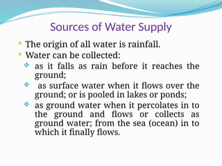
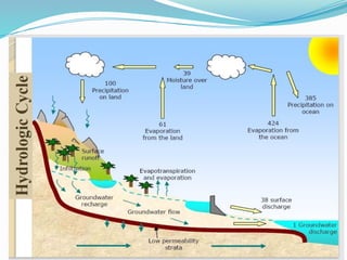
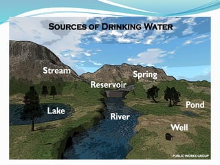
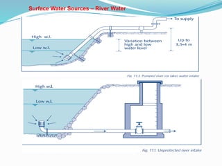
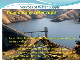
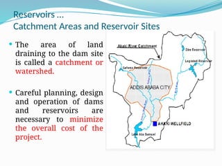
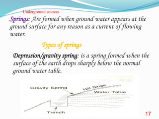
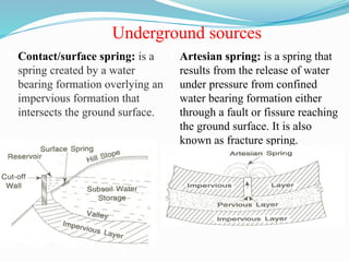
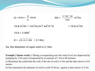
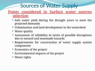
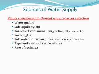
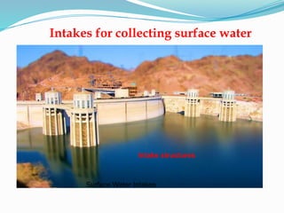
CHAPTER 3
Water Supply Sources
Prepared by:- Edimealem G. (MSC.)
Sources of Water Supply
 The origin of all water is rainfall.
 Water can be collected:
 as it falls as rain before it reaches the
ground;
 as surface water when it flows over the
ground; or is pooled in lakes or ponds;
 as ground water when it percolates in to
the ground and flows or collects as
ground water; from the sea (ocean) in to
which it finally flows.
Types of sources of water
1. Rain and snow
2. Surface water
 - Rivers
 - Lakes and
pond
 - Impounding
reservoirs
3. Underground sources
o1. Springs
- Depression springs
- Contact/surface springs
- Artesian springs
2. Infiltration galleries
3. Infiltration wells
4. wells
o - Shallow wells
o - Deep wells
4. reclaimed water
Sources of Water Supply
1. Rain:
 Rain is the principal source of all water sources.
 Rain water might contain dust, smoke, bacteria, carbon dioxide…
as falling from high altitude
 Roofs are effective catchments for rainwater harvesting and
can be integrated with tanks.
 Rainwater quality is better on open land than in urban
areas/cities.
 Rain water is soft water but flat to the taste and corrosive in
nature.
 Rainwater is not typically used as an immediate source of
Domestic Rainwater Harvesting Components
 Collection Surface: Where rainwater is
collected, typically a roof.
 Guttering: Channels rainwater from the
roof to storage.
 First-Flush System: Diverts initial dirty
water away from the tank.
 Filtration Equipment: Removes
impurities from rainwater.
 Settling Chamber: Stores debris and
allows contaminants to settle.
 Storage Tank: Stores harvested
rainwater for later use.
WASH Cluster – Water in Emergencies W
W4 8
Rainwater
Roof collected Ground collected
Health facility in an IDP camp, northern Uganda
S House / MSF-OCBA
Birkad underground rainwater collection tank, northern
Kenya
S House / AAH-US
Rain water……
Advantages of Rainwater Collection
 High-quality water
 Use of local materials and craftsmanship can be used in rain
water system construction,
 No energy costs
 Easy maintenance
 Convenience and time-saving
Disadvantages of Rainwater Collection
 High initial cost (i.e for family)
 Limited water availability (Quantity of water is dependent on
the roof area and rainy seasons)
 Flat taste compared to mineral-rich water
Sources of Water Supply
River Water
Sources of Water Supply
River Water:
 A stream or river is a body of running water on the surface of the earth, from higher to
lower ground.
 Rivers are the only surface sources of water from which maximum quantity of water
can be easily taken.
 Perennial River (water available through out the year) should always be selected for
the scheme.
 Contains lots of suspended & dissolved impurities; and if sewage is discharged into …
highly contaminated.
 Requires more treatment than other sources
 Development of rivers requires:
•Submerged intake structure
•Small diversion dams (i.e.for small streams and non-perennial river)
Surface Water Sources – River Water
Lakes or pond
A lake is a natural depression/hollow filled with water, while a
pond is an artificial depression filled with water, often created by
digging the ground.
The quantity of water in the lakes depends on its basin capacity,
catchments area, annual rainfall, porosity of the ground, etc.
It is a standing water and hence the quality is very low: (turbidity,
bacteria and pollutants, thermal stratification for deep lakes)
pond water is generally not suitable for drinking purposes and it
can be used only for bathing, washing of clothes or for animals.
Sources of Water Supply
Impounding reservoirs
 An artificial lake formed by the construction of a dam
across a valley
- Contains dam to hold water
- A spillway to allow excess water to flow
- A gate chamber with valves to regulate flow
 Regulate stream flow for beneficial use by storing
Reservoirs …
Catchment Areas and Reservoir Sites
 The area of land
draining to the dam site
is called a catchment or
watershed.
 Careful planning, design
and operation of dams
and reservoirs are
necessary to minimize
the overall cost of the
project.
Water obtained by reclamation/reclaimed water
a) Desalination: it makes saline or brackish water
drinkable
Methods include distillation, reverse osmosis,
electrodialysis, freezing, and solar evaporation
b) Reuse of treated wastewater (WW): Treated WW can
be reused for non-potable purposes such as irrigation,
industrial processes, artificial groundwater aquifer
recharge, and toilet flushing after suitable treatment.
Underground sources
Springs: Are formed when ground water appears at the
ground surface for any reason as a current of flowing
water.
Types of springs
Depression/gravity spring: is a spring formed when the
surface of the earth drops sharply below the normal
ground water table.
17
Underground sources
 Contact/surface spring: is a
spring created by a water
bearing formation overlying an
impervious formation that
intersects the ground surface.
 Artesian spring: is a spring that
results from the release of water
under pressure from confined
water bearing formation either
through a fault or fissure reaching
the ground surface. It is also
known as fracture spring.
18
Underground sources
Infiltration Gallery: is a horizontal
or nearly horizontal tunnel which is
constructed through water bearing
strata.
It is sometimes referred as horizontal
well.
Its length varied from 10 to 100m
Infiltration gallery may be
constructed with masonry or concrete
with weep holes of 5cm by 10 cm.
Underground sources
 Infiltration wells: are shallow
wells constructed under the beds of
rivers.
 They are suitable where there are
deposits of sand and porous
material at least 3m deep in river
bed.
 In the sandy beds of rivers much
quantity of water percolates down
and gets filtered through it.
20
• Jack wells are intake structures that
accumulate water from surface sources
like rivers, lakes, and reservoirs.
• They connect various infiltration wells
via porous pipes to a collecting sump,
known as a jack well.
• It is then further conveyed to the water
treatment plant.
Underground sources
oWells: Are artificial holes or pits vertically excavated for bringing ground water to the surface.
oTypes of Wells
oOpen well (Dug well): Open wells are the wells which have comparatively
large diameters but low yields (or discharges) and are not very
deep.
oDiameter =1 m to 10 m.
oYield of well= /hour or less.
oDepth=2 to 20m
oTube well: is a long pipe sunk into the ground intercepting one or
more water bearing strata.
o Diameter =80 t0 600mm
 It also classified as Shallow tube wells Deep tube wells.
 Shallow tube wells have their depths limited to about 30 m and
may have a maximum yield of about 20 m3/hour. On the other
hand deep tube wells may have maximum depth of about 600 m
and may yield more than 800 m3 hour.  600m.
21
Yield of an open wells
 The yield of an open well can be found by the
following two practical methods or yield tests.
1) Constant level pumping test
2) Recuperation test
1) Constant level pumping test
In this test, the water level is depressed by some head (H).Then the
rate of pumping is adjusted in such a way that the water level
remains constant in the well. At this time, the rate of pumping is
equal to the rate of yield from the well.
 Darcy's Law relates the rate of water
flow (Q) through a well to various
parameters. If we denote the rate of
yield as Q and the depression head as h,
and consider the flow area of water
entering the well as A (which equals the
cross-sectional area of the well bottom
if it's impervious), then Darcy's Law can
be expressed in three concise forms:
 Q = kAi
 Q = kAh/L
 Q = CAh
 where C (= k/L) is percolation intensity
coefficient
2.2 Recuperation Test
In this test, the water from the well is pumped to a depression head h1
and the pumping is stopped. The water level is rises due to the ground
water flow. The rate of yield may be calculated from the Expression
deduced below; Let h1 - Depression head when pumping was stopped.
h2 = Depression head after a certain period (t)
t=Time taken by the water level to rise from h1 to h2
h=Depression head time t
∆h=Decrease in depression head in time t
Thus in time t after the pumping was stopped the water level in the well
recuperated by (h1 – h). It again recuperates by dh in a time dt after this.
Volume of water entering the well when the head recuperated by dh is
dV = A dh ….(i)
where A = cross-sectional area of the well at its bottom.
Again if Q is the rate of. recharge into the well at time t under a depression
head h, then the volume of water entering the well in a time dt is
(K/A) is known as the specific yield or specific capacity of an open well which
is defined as the volume of water that percolates into the well per unit time per
unit area under a unit depression head.
Now, the discharge Q =K*h where h = constant depression head
Examples 1) calculate the specific capacity of an
open well from the following data:
Initial depression head =5m
Final depression head = 2m
Time of recuperation = 2 hs
Diameter of well =3m
Calculate also the specific yield & yield of the well
under head 3m
Exercise 2): Find the diameter of an open well to give the
discharge of 3 lit/sec. The depression head is 3m and specific yield 1m
3
/hr/m2
Example 3 (home work) ): During a recuperating test/ the water level was depressed by
pumping by 2.5m and is recuperated by an amount of 1.5m in 60 minutes.
a) Determine the yield from the well, if the dia of well is 2.5m and the draw down is 4.0
meters.
b) Also determine the diameter of well to yield 10 lit/sec against a draw-down of 2.5m.
Sources of Water Supply
Points considered in Surface water sources
selection
 Safe water yield during the drought years to meet the
projected demands
 Urbanization and land development in the watershed
 Water quality
 Assessment of reliability in terms of possible disruptions
due to natural and manmade hazards
 Requirements for construction of water supply system
components
 Economics of the project
 Environmental impacts of the project
 Water rights
Sources of Water Supply
Points considered in Ground water sources selection
 Water quality
 Safe aquifer yield
 Sources of contamination(gasoline, oil, chemicals)
 Water rights
 Salt water intrusion (areas near to seas or oceans)
 Type and extent of recharge area
 Rate of recharge
Water Sources development and Selection
Criteria
 Location: The sources of water should be as near as to the
town as possible.
 Quantity of water: the source of water should have
sufficient quantity of water to meet up all the water
demand through out the design period.
 Quality of water: The quality of water should be good
which can be easily and cheaply treated.
 Cost: The cost of the units of the water supply schemes
should be minimum.
 Topography: The land between the water source and
the city should not have steep valleys or tall mountains.
 Elevation of the source: The water source should be at
a higher elevation than the city so that water can flow to
the city by gravity.
Surface Water Intakes
Intakes for collecting surface water
Intake structures
Intakes for collecting surface water
 An intake is a device/structure placed in a surface-water
source to withdraw water.
 It discharges water into an intake conduit leading to the
treatment plant.
 The structure can be made of stone masonry, brick masonry,
R.C.C., or concrete blocks.
 It must be watertight and designed to withstand water
pressure, wave action, wind, and floating debris.
Key requirements of intake
The key requirements of the intake structures are that
they are:
 Reliable
 Of adequate size to provide the required quantity of water.
 Located to obtain the best quality water.
 Protected from objects that may damage equipment.
 Easy to inspect and maintain.
 Designed to minimize damage to aquatic life.
 Located to minimize navigational hazards.
Location for Intakes structures
 The intake should not be placed downstream or near where
the city disposes of sewage or wastewater, or in a location
with pollution hazards.
 The intake should be located at a place where it can draw
water even during the driest periods of the year.
 It should be as near to treatment plant as possible
 The intake structure site should allow for future expansions
to increase water withdrawal if needed.
 Magnitude and direction of stream or current velocities
should not affect the function and stability of the intake
structure.
 Reliable access roads and power sources should be available
should be near to treatment plant
 Major environmental impacts should be avoided
 The intake should not be near the navigation channel to
avoid pollution from ship and boat waste.
Location for Intake structures
Types of Intake structures
The common types of intakes used for surface-water sources are:
1-River intake
2-Canal intake
3-Reservoir intake
4-Lake intake (Simple submerged intake)
5-Intake tower
1. River Intake:
 Always located on the upstream side of the town because it is
free from the contamination.
 It is located on the river at a place where water can be
withdrawn in sufficient quantity even during the minimum
water level.
 There are two type of River intake
1- Single well type
2-Twin well type
River Intake – Single Well Type:
River Intake – Twin Well Type:
2.Canal Intake:
 The intake well is generally located in the bank of the canal, and
water enters the chamber through an inlet pipe, covered with fine
screen.
3.Reservoir Intake:
 Reservoir are very common source of water, for water
supply schemes, they are developed when dams and
weirs are constructed across the river.
Intake pipes
4.Lake Intake (Simple Submerged Intake):
 For obtaining water from lakes mostly submersible intakes are
used.
 These intakes are constructed in the bed of the lake below the
water level; so as to draw water in dry season also.
5. Tower Intake:
 It is generally used for large
scale project and on rivers or
reservoir where there is a large
fluctuation of water level.
 Control gates are provided at
various level .
 Access should be provided for
operating the gates.
Tower Intake
Intake Tower - Legedadi
River Intake components
Major components
Screen inlet
Intake pipe
Intake sump
Suction pipe
Pumps
Gate and foot valves
Access
Design Consideration for Intake Structures:
 Intake should be sufficiently heavy, so that, it may not float due
to up thrust of water.
 All the forces which are expected to work on the intake should
be carefully analyzed and intake should be designed to with
stand all of them.
 The foundation of the intake should be taken sufficiently deep.
This will avoid undermining and over turning of the structure.
 Strainers in the form of wire mesh should be provided on all the
intake inlet.
 Inlets should be such size and so located that sufficient quantity
of water can be availed from the intake in all the circumstances.
Design Criteria for intake structures
Design capacity = Q max-day
• Intake velocity should be <8 cm/s. Too low velocities that
require large intake ports should also be avoided.
• Vertical positions intake ports should be such that good quality
water is withdrawn.
• Locate the top intake port at a distance not less than 2 m from
the normal water level and the bottom port at least 1 m above
the bottom.
Intake design
 Proper design of the intake structure is one way of achieving preliminary
treatment.
 An intake generally consists of a conduit with some protective screens at open
end and gates or valves for regulating the flow.
 Bar Screens are provided to screen out larger size floating and suspended
materials. Sometimes two filters are provided successively for coarse and fine
screening.
 Inlet pipe: Location below LWL in the stream should be ≈ 1m but above stream
bed ≈ from 0.3 to 0.5 m.
 Sump=inlet well, height with FB of 0.5m
 Volume of sump -detention time. A Td of at least 20min is recommended.
 At least two sumps -to avoid interruption of service.
 Location of the bottom of the sump should be > 1.5m below the lowest stream
level or > 1m below stream bed.
 The flow velocity through the intake conduit gravity pipe should ideally range
from 0.6 to 1.5 m/sec, with a maximum limit of 2 m/sec.
Td=the length of period from the time the water enters a settling
Number of pump required?
Capacity of the sump?
Calculate the total sump height?
Example 2. Design a bell mouth canal intake for a city of
population 75000, drawing water from a canal which runs only
for 10 hours a day with a flow depth of 1.5 m. Also calculate
the head loss in the intake conduit if the treatment works are
0.25 km away. Draw a neat sketch of the canal intake. Given
the average consumption per person = 150 litters/day. The
velocity of flow through the screen and bell mouth to be less
than 0.16 m/s and 0.32 m/s respectively.
THANK
YOU
Any Questions?

chapter 3 water supply hwree updated.ppt

  • 1.
    CHAPTER 3 Water SupplySources Prepared by:- Edimealem G. (MSC.)
  • 2.
    Sources of WaterSupply  The origin of all water is rainfall.  Water can be collected:  as it falls as rain before it reaches the ground;  as surface water when it flows over the ground; or is pooled in lakes or ponds;  as ground water when it percolates in to the ground and flows or collects as ground water; from the sea (ocean) in to which it finally flows.
  • 5.
    Types of sourcesof water 1. Rain and snow 2. Surface water  - Rivers  - Lakes and pond  - Impounding reservoirs 3. Underground sources o1. Springs - Depression springs - Contact/surface springs - Artesian springs 2. Infiltration galleries 3. Infiltration wells 4. wells o - Shallow wells o - Deep wells 4. reclaimed water
  • 6.
    Sources of WaterSupply 1. Rain:  Rain is the principal source of all water sources.  Rain water might contain dust, smoke, bacteria, carbon dioxide… as falling from high altitude  Roofs are effective catchments for rainwater harvesting and can be integrated with tanks.  Rainwater quality is better on open land than in urban areas/cities.  Rain water is soft water but flat to the taste and corrosive in nature.  Rainwater is not typically used as an immediate source of
  • 7.
    Domestic Rainwater HarvestingComponents  Collection Surface: Where rainwater is collected, typically a roof.  Guttering: Channels rainwater from the roof to storage.  First-Flush System: Diverts initial dirty water away from the tank.  Filtration Equipment: Removes impurities from rainwater.  Settling Chamber: Stores debris and allows contaminants to settle.  Storage Tank: Stores harvested rainwater for later use.
  • 8.
    WASH Cluster –Water in Emergencies W W4 8 Rainwater Roof collected Ground collected Health facility in an IDP camp, northern Uganda S House / MSF-OCBA Birkad underground rainwater collection tank, northern Kenya S House / AAH-US
  • 9.
    Rain water…… Advantages ofRainwater Collection  High-quality water  Use of local materials and craftsmanship can be used in rain water system construction,  No energy costs  Easy maintenance  Convenience and time-saving Disadvantages of Rainwater Collection  High initial cost (i.e for family)  Limited water availability (Quantity of water is dependent on the roof area and rainy seasons)  Flat taste compared to mineral-rich water
  • 10.
    Sources of WaterSupply River Water
  • 11.
    Sources of WaterSupply River Water:  A stream or river is a body of running water on the surface of the earth, from higher to lower ground.  Rivers are the only surface sources of water from which maximum quantity of water can be easily taken.  Perennial River (water available through out the year) should always be selected for the scheme.  Contains lots of suspended & dissolved impurities; and if sewage is discharged into … highly contaminated.  Requires more treatment than other sources  Development of rivers requires: •Submerged intake structure •Small diversion dams (i.e.for small streams and non-perennial river)
  • 12.
    Surface Water Sources– River Water
  • 13.
    Lakes or pond Alake is a natural depression/hollow filled with water, while a pond is an artificial depression filled with water, often created by digging the ground. The quantity of water in the lakes depends on its basin capacity, catchments area, annual rainfall, porosity of the ground, etc. It is a standing water and hence the quality is very low: (turbidity, bacteria and pollutants, thermal stratification for deep lakes) pond water is generally not suitable for drinking purposes and it can be used only for bathing, washing of clothes or for animals.
  • 14.
    Sources of WaterSupply Impounding reservoirs  An artificial lake formed by the construction of a dam across a valley - Contains dam to hold water - A spillway to allow excess water to flow - A gate chamber with valves to regulate flow  Regulate stream flow for beneficial use by storing
  • 15.
    Reservoirs … Catchment Areasand Reservoir Sites  The area of land draining to the dam site is called a catchment or watershed.  Careful planning, design and operation of dams and reservoirs are necessary to minimize the overall cost of the project.
  • 16.
    Water obtained byreclamation/reclaimed water a) Desalination: it makes saline or brackish water drinkable Methods include distillation, reverse osmosis, electrodialysis, freezing, and solar evaporation b) Reuse of treated wastewater (WW): Treated WW can be reused for non-potable purposes such as irrigation, industrial processes, artificial groundwater aquifer recharge, and toilet flushing after suitable treatment.
  • 17.
    Underground sources Springs: Areformed when ground water appears at the ground surface for any reason as a current of flowing water. Types of springs Depression/gravity spring: is a spring formed when the surface of the earth drops sharply below the normal ground water table. 17
  • 18.
    Underground sources  Contact/surfacespring: is a spring created by a water bearing formation overlying an impervious formation that intersects the ground surface.  Artesian spring: is a spring that results from the release of water under pressure from confined water bearing formation either through a fault or fissure reaching the ground surface. It is also known as fracture spring. 18
  • 19.
    Underground sources Infiltration Gallery:is a horizontal or nearly horizontal tunnel which is constructed through water bearing strata. It is sometimes referred as horizontal well. Its length varied from 10 to 100m Infiltration gallery may be constructed with masonry or concrete with weep holes of 5cm by 10 cm.
  • 20.
    Underground sources  Infiltrationwells: are shallow wells constructed under the beds of rivers.  They are suitable where there are deposits of sand and porous material at least 3m deep in river bed.  In the sandy beds of rivers much quantity of water percolates down and gets filtered through it. 20 • Jack wells are intake structures that accumulate water from surface sources like rivers, lakes, and reservoirs. • They connect various infiltration wells via porous pipes to a collecting sump, known as a jack well. • It is then further conveyed to the water treatment plant.
  • 21.
    Underground sources oWells: Areartificial holes or pits vertically excavated for bringing ground water to the surface. oTypes of Wells oOpen well (Dug well): Open wells are the wells which have comparatively large diameters but low yields (or discharges) and are not very deep. oDiameter =1 m to 10 m. oYield of well= /hour or less. oDepth=2 to 20m oTube well: is a long pipe sunk into the ground intercepting one or more water bearing strata. o Diameter =80 t0 600mm  It also classified as Shallow tube wells Deep tube wells.  Shallow tube wells have their depths limited to about 30 m and may have a maximum yield of about 20 m3/hour. On the other hand deep tube wells may have maximum depth of about 600 m and may yield more than 800 m3 hour.  600m. 21
  • 22.
    Yield of anopen wells  The yield of an open well can be found by the following two practical methods or yield tests. 1) Constant level pumping test 2) Recuperation test 1) Constant level pumping test In this test, the water level is depressed by some head (H).Then the rate of pumping is adjusted in such a way that the water level remains constant in the well. At this time, the rate of pumping is equal to the rate of yield from the well.
  • 23.
     Darcy's Lawrelates the rate of water flow (Q) through a well to various parameters. If we denote the rate of yield as Q and the depression head as h, and consider the flow area of water entering the well as A (which equals the cross-sectional area of the well bottom if it's impervious), then Darcy's Law can be expressed in three concise forms:  Q = kAi  Q = kAh/L  Q = CAh  where C (= k/L) is percolation intensity coefficient
  • 24.
    2.2 Recuperation Test Inthis test, the water from the well is pumped to a depression head h1 and the pumping is stopped. The water level is rises due to the ground water flow. The rate of yield may be calculated from the Expression deduced below; Let h1 - Depression head when pumping was stopped. h2 = Depression head after a certain period (t) t=Time taken by the water level to rise from h1 to h2 h=Depression head time t ∆h=Decrease in depression head in time t
  • 25.
    Thus in timet after the pumping was stopped the water level in the well recuperated by (h1 – h). It again recuperates by dh in a time dt after this. Volume of water entering the well when the head recuperated by dh is dV = A dh ….(i) where A = cross-sectional area of the well at its bottom. Again if Q is the rate of. recharge into the well at time t under a depression head h, then the volume of water entering the well in a time dt is
  • 27.
    (K/A) is knownas the specific yield or specific capacity of an open well which is defined as the volume of water that percolates into the well per unit time per unit area under a unit depression head. Now, the discharge Q =K*h where h = constant depression head Examples 1) calculate the specific capacity of an open well from the following data: Initial depression head =5m Final depression head = 2m Time of recuperation = 2 hs Diameter of well =3m Calculate also the specific yield & yield of the well under head 3m
  • 28.
    Exercise 2): Findthe diameter of an open well to give the discharge of 3 lit/sec. The depression head is 3m and specific yield 1m 3 /hr/m2
  • 29.
    Example 3 (homework) ): During a recuperating test/ the water level was depressed by pumping by 2.5m and is recuperated by an amount of 1.5m in 60 minutes. a) Determine the yield from the well, if the dia of well is 2.5m and the draw down is 4.0 meters. b) Also determine the diameter of well to yield 10 lit/sec against a draw-down of 2.5m.
  • 30.
    Sources of WaterSupply Points considered in Surface water sources selection  Safe water yield during the drought years to meet the projected demands  Urbanization and land development in the watershed  Water quality  Assessment of reliability in terms of possible disruptions due to natural and manmade hazards  Requirements for construction of water supply system components  Economics of the project  Environmental impacts of the project  Water rights
  • 31.
    Sources of WaterSupply Points considered in Ground water sources selection  Water quality  Safe aquifer yield  Sources of contamination(gasoline, oil, chemicals)  Water rights  Salt water intrusion (areas near to seas or oceans)  Type and extent of recharge area  Rate of recharge
  • 32.
    Water Sources developmentand Selection Criteria  Location: The sources of water should be as near as to the town as possible.  Quantity of water: the source of water should have sufficient quantity of water to meet up all the water demand through out the design period.  Quality of water: The quality of water should be good which can be easily and cheaply treated.  Cost: The cost of the units of the water supply schemes should be minimum.  Topography: The land between the water source and the city should not have steep valleys or tall mountains.  Elevation of the source: The water source should be at a higher elevation than the city so that water can flow to the city by gravity.
  • 33.
    Surface Water Intakes Intakesfor collecting surface water Intake structures
  • 34.
    Intakes for collectingsurface water  An intake is a device/structure placed in a surface-water source to withdraw water.  It discharges water into an intake conduit leading to the treatment plant.  The structure can be made of stone masonry, brick masonry, R.C.C., or concrete blocks.  It must be watertight and designed to withstand water pressure, wave action, wind, and floating debris.
  • 35.
    Key requirements ofintake The key requirements of the intake structures are that they are:  Reliable  Of adequate size to provide the required quantity of water.  Located to obtain the best quality water.  Protected from objects that may damage equipment.  Easy to inspect and maintain.  Designed to minimize damage to aquatic life.  Located to minimize navigational hazards.
  • 36.
    Location for Intakesstructures  The intake should not be placed downstream or near where the city disposes of sewage or wastewater, or in a location with pollution hazards.  The intake should be located at a place where it can draw water even during the driest periods of the year.  It should be as near to treatment plant as possible  The intake structure site should allow for future expansions to increase water withdrawal if needed.
  • 37.
     Magnitude anddirection of stream or current velocities should not affect the function and stability of the intake structure.  Reliable access roads and power sources should be available should be near to treatment plant  Major environmental impacts should be avoided  The intake should not be near the navigation channel to avoid pollution from ship and boat waste. Location for Intake structures
  • 38.
    Types of Intakestructures The common types of intakes used for surface-water sources are: 1-River intake 2-Canal intake 3-Reservoir intake 4-Lake intake (Simple submerged intake) 5-Intake tower
  • 39.
    1. River Intake: Always located on the upstream side of the town because it is free from the contamination.  It is located on the river at a place where water can be withdrawn in sufficient quantity even during the minimum water level.  There are two type of River intake 1- Single well type 2-Twin well type
  • 40.
    River Intake –Single Well Type:
  • 41.
    River Intake –Twin Well Type:
  • 42.
    2.Canal Intake:  Theintake well is generally located in the bank of the canal, and water enters the chamber through an inlet pipe, covered with fine screen.
  • 43.
    3.Reservoir Intake:  Reservoirare very common source of water, for water supply schemes, they are developed when dams and weirs are constructed across the river. Intake pipes
  • 44.
    4.Lake Intake (SimpleSubmerged Intake):  For obtaining water from lakes mostly submersible intakes are used.  These intakes are constructed in the bed of the lake below the water level; so as to draw water in dry season also.
  • 45.
    5. Tower Intake: It is generally used for large scale project and on rivers or reservoir where there is a large fluctuation of water level.  Control gates are provided at various level .  Access should be provided for operating the gates.
  • 46.
  • 47.
  • 48.
    River Intake components Majorcomponents Screen inlet Intake pipe Intake sump Suction pipe Pumps Gate and foot valves Access
  • 49.
    Design Consideration forIntake Structures:  Intake should be sufficiently heavy, so that, it may not float due to up thrust of water.  All the forces which are expected to work on the intake should be carefully analyzed and intake should be designed to with stand all of them.  The foundation of the intake should be taken sufficiently deep. This will avoid undermining and over turning of the structure.  Strainers in the form of wire mesh should be provided on all the intake inlet.  Inlets should be such size and so located that sufficient quantity of water can be availed from the intake in all the circumstances.
  • 50.
    Design Criteria forintake structures Design capacity = Q max-day • Intake velocity should be <8 cm/s. Too low velocities that require large intake ports should also be avoided. • Vertical positions intake ports should be such that good quality water is withdrawn. • Locate the top intake port at a distance not less than 2 m from the normal water level and the bottom port at least 1 m above the bottom.
  • 51.
    Intake design  Properdesign of the intake structure is one way of achieving preliminary treatment.  An intake generally consists of a conduit with some protective screens at open end and gates or valves for regulating the flow.  Bar Screens are provided to screen out larger size floating and suspended materials. Sometimes two filters are provided successively for coarse and fine screening.  Inlet pipe: Location below LWL in the stream should be ≈ 1m but above stream bed ≈ from 0.3 to 0.5 m.  Sump=inlet well, height with FB of 0.5m  Volume of sump -detention time. A Td of at least 20min is recommended.  At least two sumps -to avoid interruption of service.  Location of the bottom of the sump should be > 1.5m below the lowest stream level or > 1m below stream bed.  The flow velocity through the intake conduit gravity pipe should ideally range from 0.6 to 1.5 m/sec, with a maximum limit of 2 m/sec. Td=the length of period from the time the water enters a settling
  • 52.
    Number of pumprequired? Capacity of the sump? Calculate the total sump height?
  • 54.
    Example 2. Designa bell mouth canal intake for a city of population 75000, drawing water from a canal which runs only for 10 hours a day with a flow depth of 1.5 m. Also calculate the head loss in the intake conduit if the treatment works are 0.25 km away. Draw a neat sketch of the canal intake. Given the average consumption per person = 150 litters/day. The velocity of flow through the screen and bell mouth to be less than 0.16 m/s and 0.32 m/s respectively.
  • 61.