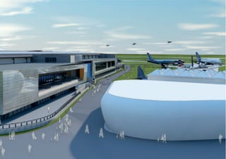
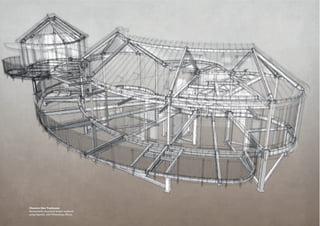
3. InnovativeVectorworksbim
Chapter 1090
the practice Terence O’Rourke is a
multi-disciplinary consultancy, based in
London and Bournemouth, providing
planning, environment consultancy
and architectural services. Within our
design disciplines we have urban
designers, masterplanners, landscape
architects and architects who work
together on projects that range widely
in type, scale and complexity. We use
our team’s unique skill-set in the
planning, design and environmental
professions, working closely together
as an integrated unit, to deal creatively
with challenging project constraints to
deliver bespoke solutions to our clients
throughout the uk.
Our record shows an inspired and imaginative response on
a range of high-profile projects, unlocking opportunities
at the forefront of best practice and at the cutting edge of
commercial thinking. We have a close relationship with
our clients, taking care to listen to them and understand
their objectives so that we often exceed their expectations.
This approach creates comprehensive, innovative solu-
tions to even the most complex planning, environmental
and design challenges.
the journey into bim Since their inception, tor’s design
disciplines have used Vectorworks software for master-
planning, landscape and architectural design. This has
mainly been in a 2d cad mode, but using features such as
practice
Terence O’Rourke Ltd
authors
Dan Fairley and
Christian Spendier
location
Bournemouth, Dorset
employees
73 (24 in design
disciplines)
founded
1985
directors
Terry Williams,
Director of Architecture
technology
Vectorworks Architect
and Landmark (Mac
platform), SketchUp,
Adobe Creative Cloud
sectors
Masterplanning,
residential, commercial,
leisure, industrial, infra-
structure, conservation
contact
dan.fairley@torltd.co.uk
website
www.torltd.co.uk Farnborough Hall 1-1a
Working visualisation of planning
application scheme, produced using
Renderworks and Photoshop
6. Multi-disciplinary bim 93
workgroup referencing to facilitate team working. Careful
use of Vectorworks classes/layers, opacities, patterns and
images lends a ‘soft’ visual appearance to masterplans,
landscape plans, and architectural plans and elevations.
In the past, we had used earlier versions of Vectorworks
Architect for some 3d modelling and SketchUp for master-
planning and concept design.
As the prominence and awareness of bim grew over the
last few years, we made our first steps towards using
Vectorworks for 3d bim modelling in architectural projects
in 2010. A couple of members of our architectural team,
who had a particular interest and enthusiasm, started by
using bim on small, simple projects. The learning process
was largely self-directed, making use of online resources
and forums to assist with the queries that invariably arose.
While these ‘bim champions’ developed their knowledge,
other team members were encouraged to use bim methods
on their projects, with the early adopters providing
support. Currently, all members of our architectural
team use Vectorworks Architect in a 3d capacity for most
new projects, and we are currently investigating how the
3d tools within Vectorworks Landmark can be used to
introduce a suitable bim methodology to masterplanning
and landscape design.
The first ‘live’ bim project we delivered was the Chewton
Glen Treehouses, in 2011-2012. This innovative and
uniquely constrained project was an ideal opportunity
to explore the particular advantages offered by a bim
methodology, and clearly demonstrated to us how project
changes could be accommodated quickly and alternative
scenarios explored.
Co-operation with a wider project team was limited to the
importing of structural models for co-ordination; this was
due in part to the simple nature of the services instal-
lations, and also to the working methods used by other
design team members at the time.
Two current projects that demonstrate how our use of bim
has evolved are Hall 1-1a for Farnborough International
and the new Tropical House and Energy Centre at Marwell
Zoo. Both are complex, bespoke building types with specific
performance requirements, and use complex architectural
forms for an innovative design. At the time of writing,
these projects have only been developed to early stages
(planning/riba Stage 3), but it is intended that a full bim
delivery process will be required from design team mem-
bers throughout project delivery and post-completion.
As our experience and fluency in using Vectorworks Archi-
tect for bim has developed, it has become much more
useful to us as a design tool at early project stages, enabling
options and approaches to be explored with the additional
benefit of quick working visualisations being readily avail-
able from the building model.
project 1/3 medium
Chewton Glen Treehouses
This project involved the construction of six free-standing
lodges set within the tree canopy of a woodland valley at
Chewton Glen Hotel, on the edge of the New Forest. Each
treehouse contains two exclusive luxury hotel suites within
a curved building form, carefully orientated to maximise
Chewton Glen
Photograph of
completed project
courtesyofchewtonglenhotel
7. InnovativeVectorworksbim
Chapter 1094
sun path and views out while remaining secluded. The
woodland location demanded careful foundation design,
and individual servicing was needed to minimise the
scheme’s impact on the setting. In addition to the design
and construction constraints imposed by the site, the pro-
ject had to be delivered in a tight time-frame and to high
standards of finish to be available to guests for the summer
season of 2012.
Due to these particular project requirements and the
unusual architectural form, which necessitated a high
level of structural co-ordination, this project was chosen
as the most suitable for our first live use of bim working
methods. We modelled the two treehouse types in Vector-
works Architect, with models from the structural engineer
and the steel fabricator imported for co-ordination.
Mechanical and electrical information was available only
in 2d form. To facilitate teamwork within our office, the
site plan file and internal fit-out models were workgroup-
referenced to the building models from separate files.
This required good communication by the project team to
ensure the most current versions of files were referenced.
Because this project marked the start of our journey along
the bim learning curve, we were not always able to use
Vectorworks Architect and its built-in tools to their full
capability to model the project, but other tools were easily
integrated. Some bespoke items, such as the loft stair, were
modelled in SketchUp before being imported into the
Vectorworks model. We drew the site plans and sections
using 2d methods, since the skills were not yet in place to
make full use of site terrain modelling.
The real advantage of bim for this project, however, was
the ability to make changes to the construction and update
the drawings quickly. This proved extremely useful when
investigating alternatives during value engineering. One
example of this is the curved, pitched roof, finished with
standing-seam aluminium. Initially it was proposed that
this would have a continuously curved ply deck sub-
strate to maintain the curved appearance, but when the
contractor noted that a faceted ply deck would be cheaper
and quicker to install, we were able to model this with the
facets aligned with the roof seams to demonstrate that the
curved appearance could still be maintained.
This project demonstrated to us the advantages of bim in
delivery and design development, even for a scheme of a
highly bespoke nature, and served as a springboard for the
wider adoption of bim within Terence O’Rourke.
project 2/3 large
Farnborough International Hall 1-1a
Hall 1-1a at Farnborough Airport is a new 21,000 sq m
exhibition and conference building for which planning
permission was obtained in 2014. It is intended to replace
one of the temporary exhibition structures erected for
the biennial Farnborough International Airshow. As
well as serving the exhibition, media centre and catering
requirements of the Airshow, this building needed to
▼ Internal cutaway
Drawing of Hall 1-1a
showing seating layouts
8. Multi-disciplinary bim 95
provide a flexible facility to accommodate the wide range
of exhibition, trade show, conference and other events
hosted by Farnborough International on the site outside
the Airshow.
In addition to a 48m clear span, 9m high, 12,500 sq m
exhibition hall, Hall 1-1a includes 3,600 square metres of
flexible function areas (one space accommodating theatre-
style seating for up to 1,200 people), two double-height
foyers linked at both levels by a concourse, and catering
support facilities to supply up to 1,500 meals.
Flexibility and functionality were the key design drivers for
this project, and required careful and thorough develop-
ment of the brief, with a number of design iterations need-
ed to fully explore the types, dimensions and configuration
of spaces. The use of bim techniques has been invaluable
in this process, enabling changes and amendments to be
quickly made and alternative scenarios easily explored.
We have used the Space tool, linked to custom worksheets,
to generate accommodation schedules that can be contin-
uously updated as the design develops. These worksheets
have been used as the basis of a database of room data
sheets (rds) for the project to track the key performance
criteria for each space. As well as providing a single loca-
tion for the main design criteria, these will assist the client
in future discussions with potential exhibitors.
The project progressed extremely quickly from initial
outline design to planning application, and cross-sections,
rendered elevations and 3d visualisations were readily
generated from the building model using Renderworks.
This demonstrated to us the advantage of ‘live’ sections
and elevations that could be quickly updated as the design
evolved, while still achieving the desired ‘soft’ appearance
that we use for presenting 2d elevations.
We have also been able to use the developing building
model to produce progress visualisations to explore design
concepts. In particular, we were able to export a 3d version
of the planning application proposals that the client’s
visualisation consultants could bring into a wider site model
for animated marketing visuals produced using computer
game engines.
project 3/3 medium
Marwell Zoo Tropical House
The new tropical house at Marwell Zoo in Hampshire is
intended to replace the existing Tropical World facility. It
incorporates an energy centre using a sustainable energy
source to power both the tropical house and other exhibits
within the park. The building features an elongated ‘S’-
shaped plan with an elevated entry and a lower-level exit.
The tropical house to the south is split from the energy
centre to the north by a central concrete thermal wall.
The building is enclosed by a lightweight curved roof, to
be fabricated from etfe membrane, supported by a curved
steel structure. This complex architectural form suggested
to us at an early stage that using 3d bim was the most
rational and efficient method to document the building.
The initial setting-out was established by a 2d plan grid in
a regular arrangement, dividing the building into a series
of bays, which meant that the building could be easily
extended or reduced through the design process to meet
performance requirements and cost limits.
Breaking the building into a series of bays to achieve the
overall form ensured both constructional efficiency and
drawn efficiency. For example, the main structural elements
Tropical House
Renderworks images
9. InnovativeVectorworksbim
Chapter 1096
were formed as curved circular beams in 3d using the
Extrude Along Path command in Vectorworks Architect,
and the completed elements were then converted to a 3d
symbol with ifc data applied. These symbols were next set
out on the centre point of the set circular grid and dupli-
cated and rotated to grid.
To form the ‘pillows’ of the etfe membrane, a curve was
drawn following the top of the beams either side of a bay,
with a third line connecting these at the base. These were
then converted to spline lines and, with the Surface Array
tool, a curved pillow shape was generated that closely
resembled a typical etfe installation.
The geometric demands of this project required us to
make much greater use of the 3d modelling tools within
Vectorworks Architect, rather than using standard plug-in
objects. This had the advantage of allowing easy adjust-
ment of the design by altering the generating geometry,
but we also learned the importance of adding the right
ifc data so that all information within the model could be
exchanged with other design team members.
The production of a 3d model early in the design process
presented clear advantages for design exploration and
demonstration of our proposals to the client and design
team. We were able to quickly produce animated walk-
throughs and 3d views from the model, using some post-
processing in other software packages to add the level of
softness and ‘sketchiness’ that we wanted for this early stage
of presentation.
Conclusions
Since the majority of our team are experienced 2d users of
Vectorworks Architect, and many have previous experi-
ence of other 3d packages, we found the move from 2d to
3d bim use of Vectorworks was more of an evolutionary
process than revolutionary.
We have now reached the point where all members of our
architectural team are using bim for new projects, right
from the initial design stages, to generate plans, sections,
elevations and 3d views from a single model. Using
Renderworks, we are able to replicate the soft look and
detailed textures on elevations that we previously achieved
by 2d methods. We can produce full sets of drawings at
early schematic stages much more quickly using bim, and
can incorporate changes and explore design alternatives
much more responsively. It is also a great deal quicker
to move from a planning/schematic design to a detailed
design. The main benefit of bim has been enhanced
responsiveness to project change pressures, such as a
changing brief, planning process feedback, or incorporat-
ing value engineering changes. We have noted that bim has
made significant improvements to our cost-effectiveness
and efficiency.
Most of the discussion, training and knowledge base on bim
seems focused on the construction stages of project deliv-
ery and less on the project concept and masterplanning
stage. We will need to undertake more investigation to
make full use of bim within our other design disciplines.
We were aware of, but have now seen first-hand, how bim
front-loads a project with a much greater degree of design
development and effort at the early stages. Along with
the wider profession, our fee structures need to evolve to
capture this.
Co-operation with other consultants has been somewhat
limited up to this point, mainly due to the scope and
extent of our involvement in certain projects and the fact
that many consultants that we work with still operate 2d
workflows. We have used 3d structural and steelwork
models for co-ordination purposes and will continue to
develop our skills and methods in this area. For larger
projects, where several members of our team are working
on the same model, we look forward to the Project Sharing
features in Vectorworks Architect 2016.
Curved steel and etfe roof
Complex forms were drawn
using free-form modelling