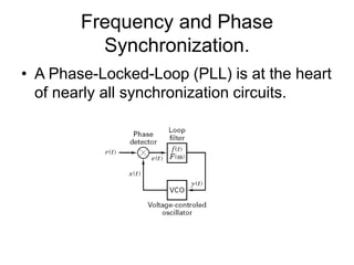
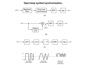
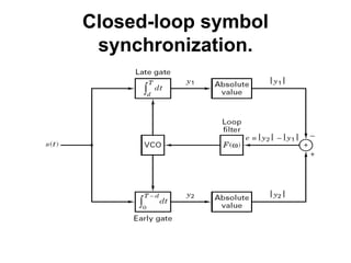
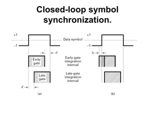
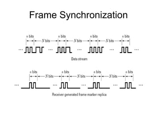
EEE4026F Digital
Communication Engineering
with
Mqhele E. Dlodlo and Emmanuel O. Bejide
backed by
Bernard Sklar and Kamilo Feher
Chapter 10 Synchronisation
• Lecture 21: Introduction & Receiver
Synchronisation
– Introduction
• Definition
• Cost-Benefit Issues
• Approach & Assumptions
– Receiver Synch
• Frequency & Phase Synch
• Lecture 22: Receiver Synch (cont’d)
– Costas Loops
– High-Order Suppressed Carrier
Loops
– Acquisition
– Phase Tracking Errors &
Performance
– Spectrum Analysis Techniques
– Symbol Synch – Discrete Case
• Lecture 23: Receiver Synch (cont’d)
– Synch with CPM
– Data-Aided Synch
– Non-Data-Aided Synch
– Frame Synch
• Lecture 24: Network Synch
– Open-Loop Transmitter
Synch
– Closed-Loop Transmitter
Synch
– Conclusion
Synchronization Defined
• Phase synchronization.
• Symbol Synchronization.
• Frame Synchronization.
• Frequency Synchronization.
• Network Synchronization.
Tradeoff
• There are added cost to receiver design due to
the implementation of acquisition and tracking
circuits.
• Time required for synchronization to be
achieved.
• Energy expended, for instance on pilot signals,
for the purpose of synchronization.
• Complexity due to error control.
– Frame, block, message synchronization.
• Complexity due to spread spectrum technique.
– PN sequence synchronization.
Receiver Synchronization.
• All digital communication receivers require
some degree of synchronization to the
incoming signal.
Frequency and Phase
Synchronization.
• A Phase-Locked-Loop (PLL) is at the heart
of nearly all synchronization circuits.
Frequency and Phase
Synchronization.
• PLL are servo-control loops, whose
controlled parameter is the phase of a
locally generated replica of the incoming
carrier signal.
• Components of a PLL:
– A phase detector
– A loop filter
– A voltage-controlled oscillator (VCO).
Frequency and Phase
Synchronization.
• A phase detector determines the difference in phase
between the incoming signal and the reference signal.
• The loop filter controls the response of the PLL to the
error signal.
• The VCO is an oscillator whose output frequency is a
linear function of its voltage over some range of input
and output.
– +ve signal increase frequency beyond the uncontrolled value.
– -ve signal  reduce frequency below the uncontrolled value.
Frequency and Phase
Synchronization.
• For a normalized
input signal of the
form:
• Consider a
normalized VCO
output of the form:
)]
(
cos[
)
( 0 t
t
w
t
r 


)]
(
ˆ
sin[
2
)
( 0 t
t
w
t
x 



Frequency and Phase
Synchronization.
• Output error signal at
the phase detector
output:
• If the filter output is
low-pass, we will
have
)]
(
ˆ
)
(
2
sin[
)]
(
ˆ
)
(
sin[
)]
(
cos[
)]
(
ˆ
sin[
2
)
(
)
(
)
(
0
0
0
t
t
t
w
t
t
t
t
w
t
t
w
t
r
t
x
t
e















)]
(
ˆ
)
(
sin[
)
( t
t
t
y 
 

Frequency and Phase
Synchronization.
• The low pass filter produces an output that is
solely the function of difference in phase between
the two signals.
• The VCO output will be a linear function of y(t).
• Deviation in frequency is given as
)
(
*
)]
(
ˆ
)
(
[
)
(
*
)
(
)
(
)]
(
ˆ
[
)
(
t
f
t
t
K
t
f
t
e
K
t
y
K
dt
t
d
t
o
o
o










Gain of the VCO Loop filter impulse response
Frequency and Phase
Synchronization.
• The Fourier transform of the difference equation
leads to
Reorganizing, we have
)
(
*
)]
(
ˆ
)
(
[
)
(
*
)
(
)
(
)]
(
ˆ
[
)
(
t
f
t
t
K
t
f
t
e
K
t
y
K
dt
t
d
t
o
o
o










)
(
)]
(
ˆ
)
(
[
)
( w
F
K
j o 


 




)
(
)
(
)
(
)
(
)
(
ˆ




H
w
F
K
j
w
F
K
o
o





Closed-loop transfer function
Frequency and Phase
Synchronization.
• The order of the PLL is the order of the
highest term in jwin the denominator of
H(w).
Steady state tracking Characteristic
of the PLL.
• The expression for the Fourier transform of the
phase error can be given as:
• The steady-state error is the residual error after all
transients have died away.
)
(
)
(
)
(
))
(
1
(
)
(
ˆ
)
(
)}
(
{
)
(
w
F
K
j
j
H
t
e
F
E
o



















)
(
)
(
)
(
)}
(
{
)
(
2
0
lim
lim w
F
K
j
j
t
e
F
j
t
e
o
j
t 





 




Performance in noise
• The input might be noisy, as is the case in many
communication systems.
• n(t) can be expanded into quadrature
components.
)
(
]
cos[
)
( 0 t
n
t
w
t
r 

 
t
w
t
n
t
w
t
n
t
n s
c 0
0 sin
)
(
cos
)
(
)
( 

Performance in noise
• The output of the phase detector can be written as
• The loop filter eliminates the high-frequency components. We
are then left with
• Let us denote the variance of n/(t) by σn.
• It can be shown that the variance of the output phase is:
• For the special case of white noise
• This is related to the
frequency)
carrier
the
at twice
terms
(
]
ˆ
cos[
)
(
]
ˆ
sin[
)
(
]
ˆ
sin[
)
(
)
(
)
( 




 


 t
n
t
n
t
r
t
x
t
e c
s
]
ˆ
cos[
)
(
]
ˆ
sin[
)
(
]
ˆ
sin[
)
( 


 t
n
t
n
t
n c
s 









d
H
G 2
2
ˆ |
)
(
|
)
(
2
1









d
H
No 2
2
ˆ |
)
(
|
2 




L
oB
N
2
2
ˆ 


Acqusition.
• Acquisition is the process of getting the
PLL to lock with the incoming signal.
– Aided acquisition
• With the aid of external circuits.
– Self-acqusition
• Without the aid of extrnal signals
Symbol synchronization.
• Symbol synchronization is needed in order to achieve
optimum demodulation.
– Non-Data Aided (NDA).
– Data Aided (DA).
Open-loop symbol synchronization.
Closed-loop symbol
synchronization.
Closed-loop symbol
synchronization.
Frame Synchronization

Chapter 10- Synchronisation.ppt

  • 1.
    EEE4026F Digital Communication Engineering with MqheleE. Dlodlo and Emmanuel O. Bejide backed by Bernard Sklar and Kamilo Feher
  • 2.
    Chapter 10 Synchronisation •Lecture 21: Introduction & Receiver Synchronisation – Introduction • Definition • Cost-Benefit Issues • Approach & Assumptions – Receiver Synch • Frequency & Phase Synch • Lecture 22: Receiver Synch (cont’d) – Costas Loops – High-Order Suppressed Carrier Loops – Acquisition – Phase Tracking Errors & Performance – Spectrum Analysis Techniques – Symbol Synch – Discrete Case • Lecture 23: Receiver Synch (cont’d) – Synch with CPM – Data-Aided Synch – Non-Data-Aided Synch – Frame Synch • Lecture 24: Network Synch – Open-Loop Transmitter Synch – Closed-Loop Transmitter Synch – Conclusion
  • 3.
    Synchronization Defined • Phasesynchronization. • Symbol Synchronization. • Frame Synchronization. • Frequency Synchronization. • Network Synchronization.
  • 4.
    Tradeoff • There areadded cost to receiver design due to the implementation of acquisition and tracking circuits. • Time required for synchronization to be achieved. • Energy expended, for instance on pilot signals, for the purpose of synchronization. • Complexity due to error control. – Frame, block, message synchronization. • Complexity due to spread spectrum technique. – PN sequence synchronization.
  • 5.
    Receiver Synchronization. • Alldigital communication receivers require some degree of synchronization to the incoming signal.
  • 6.
    Frequency and Phase Synchronization. •A Phase-Locked-Loop (PLL) is at the heart of nearly all synchronization circuits.
  • 7.
    Frequency and Phase Synchronization. •PLL are servo-control loops, whose controlled parameter is the phase of a locally generated replica of the incoming carrier signal. • Components of a PLL: – A phase detector – A loop filter – A voltage-controlled oscillator (VCO).
  • 8.
    Frequency and Phase Synchronization. •A phase detector determines the difference in phase between the incoming signal and the reference signal. • The loop filter controls the response of the PLL to the error signal. • The VCO is an oscillator whose output frequency is a linear function of its voltage over some range of input and output. – +ve signal increase frequency beyond the uncontrolled value. – -ve signal  reduce frequency below the uncontrolled value.
  • 9.
    Frequency and Phase Synchronization. •For a normalized input signal of the form: • Consider a normalized VCO output of the form: )] ( cos[ ) ( 0 t t w t r    )] ( ˆ sin[ 2 ) ( 0 t t w t x    
  • 10.
    Frequency and Phase Synchronization. •Output error signal at the phase detector output: • If the filter output is low-pass, we will have )] ( ˆ ) ( 2 sin[ )] ( ˆ ) ( sin[ )] ( cos[ )] ( ˆ sin[ 2 ) ( ) ( ) ( 0 0 0 t t t w t t t t w t t w t r t x t e                )] ( ˆ ) ( sin[ ) ( t t t y    
  • 11.
    Frequency and Phase Synchronization. •The low pass filter produces an output that is solely the function of difference in phase between the two signals. • The VCO output will be a linear function of y(t). • Deviation in frequency is given as ) ( * )] ( ˆ ) ( [ ) ( * ) ( ) ( )] ( ˆ [ ) ( t f t t K t f t e K t y K dt t d t o o o           Gain of the VCO Loop filter impulse response
  • 12.
    Frequency and Phase Synchronization. •The Fourier transform of the difference equation leads to Reorganizing, we have ) ( * )] ( ˆ ) ( [ ) ( * ) ( ) ( )] ( ˆ [ ) ( t f t t K t f t e K t y K dt t d t o o o           ) ( )] ( ˆ ) ( [ ) ( w F K j o          ) ( ) ( ) ( ) ( ) ( ˆ     H w F K j w F K o o      Closed-loop transfer function
  • 13.
    Frequency and Phase Synchronization. •The order of the PLL is the order of the highest term in jwin the denominator of H(w).
  • 14.
    Steady state trackingCharacteristic of the PLL. • The expression for the Fourier transform of the phase error can be given as: • The steady-state error is the residual error after all transients have died away. ) ( ) ( ) ( )) ( 1 ( ) ( ˆ ) ( )} ( { ) ( w F K j j H t e F E o                    ) ( ) ( ) ( )} ( { ) ( 2 0 lim lim w F K j j t e F j t e o j t            
  • 15.
    Performance in noise •The input might be noisy, as is the case in many communication systems. • n(t) can be expanded into quadrature components. ) ( ] cos[ ) ( 0 t n t w t r     t w t n t w t n t n s c 0 0 sin ) ( cos ) ( ) (  
  • 16.
    Performance in noise •The output of the phase detector can be written as • The loop filter eliminates the high-frequency components. We are then left with • Let us denote the variance of n/(t) by σn. • It can be shown that the variance of the output phase is: • For the special case of white noise • This is related to the frequency) carrier the at twice terms ( ] ˆ cos[ ) ( ] ˆ sin[ ) ( ] ˆ sin[ ) ( ) ( ) (           t n t n t r t x t e c s ] ˆ cos[ ) ( ] ˆ sin[ ) ( ] ˆ sin[ ) (     t n t n t n c s           d H G 2 2 ˆ | ) ( | ) ( 2 1          d H No 2 2 ˆ | ) ( | 2      L oB N 2 2 ˆ   
  • 17.
    Acqusition. • Acquisition isthe process of getting the PLL to lock with the incoming signal. – Aided acquisition • With the aid of external circuits. – Self-acqusition • Without the aid of extrnal signals
  • 18.
    Symbol synchronization. • Symbolsynchronization is needed in order to achieve optimum demodulation. – Non-Data Aided (NDA). – Data Aided (DA).
  • 19.
  • 20.
  • 21.
  • 22.