The document outlines a course on network devices and configuration, focusing on practical skills like VLAN creation, router management, and switch configuration. It details various types of cables, IP protocols (IPv4 and IPv6), and VLAN advantages, as well as assessment methods for student evaluation. Key concepts, including port management, VLAN assignment methods, and networking best practices, are also covered to enhance understanding of network infrastructure.
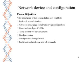
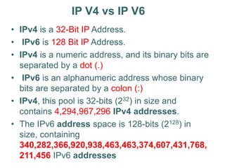
![Catalyst IOS Intro
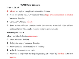
• User EXEC mode and Privileged EXEC mode.
– enable command.
• IOS based switch is just like the router IOS.
– configure command – go to global config mode.
– copy running-config startup-config– to save config to NVRAM.
– show startup-config
• Host Name configuration -1-255 characters
– hostname [name] eg. hostname S1
• Comment to help identify the interface.
– description [description-string] - interface config. mode
– Use quotes when using spaces in string.
• IOS-based: same as on a router.
– access help by entering ?](https://image.slidesharecdn.com/chapter1switchnetworkdevice1-240529183042-05e953fc/85/Chapter-1-Switch-Network-Device-1-ppt-20-320.jpg)
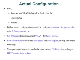
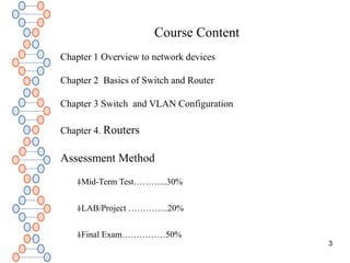
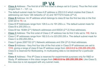
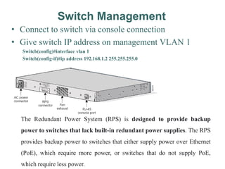
![Remote Access to Switch
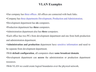
• To telnet, ping, or globally manage the switch:
– Enter an IP address and management VLAN.
• Configuration
– interface vlan 1
– ip address [address][mask]
– ip default-gateway [address]
– Verify with show ip interface
IT_Switch# conf t
IT_Switch(config)#interface vlan 1
IT_Switch(config-if)#ip address 192.168.1.2 255.255.255.0
IT_Switch(config-if)#ip default-gateway 192.168.1.1
IT_Switch#show ip interface](https://image.slidesharecdn.com/chapter1switchnetworkdevice1-240529183042-05e953fc/85/Chapter-1-Switch-Network-Device-1-ppt-23-320.jpg)
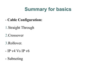
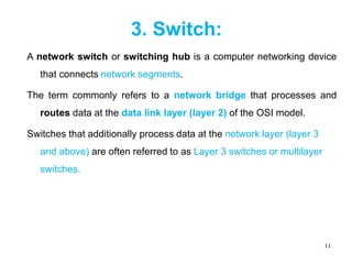
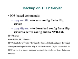
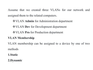
![IT_Switch>enable
IT_Switch#configure terminal
IT_Switch(config)#int fa 0/1
IT_Switch(config-if)#duplex full
IT_Switch(config-if)#
%LINK-3-UPDOWN: Interface FastEthernet0/1, changed state to down
%LINEPROTO-5-UPDOWN: Line protocol on Interface FastEthernet0/1, changed state to
down
IT_Switch(config-if)#speed 100
IT_Switch(config-if)#end
IT_Switch#
%SYS-5-CONFIG_I: Configured from console by console
IT_Switch#copy running-config startup-config
Destination filename [startup-config]?
Building configuration...](https://image.slidesharecdn.com/chapter1switchnetworkdevice1-240529183042-05e953fc/85/Chapter-1-Switch-Network-Device-1-ppt-25-320.jpg)
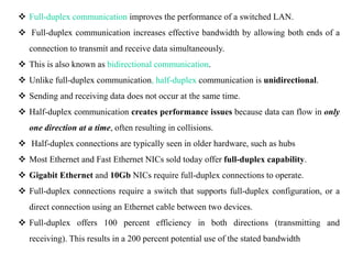
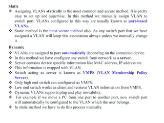
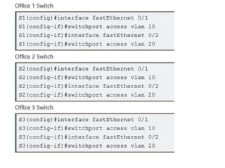
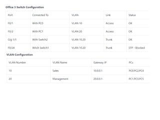
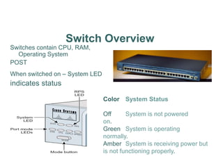
![In practice lab network Office1 Switch is configured as VTP Server(VLAN Trunking
Protocol). Office2 and Office3 switches are configured as VTP clients. We only need
to create VLANs in VTP Server. VTP Server will propagate this information to all VTP
clients automatically.
vlan vlan number command is used to create the VLAN.
Assigning VLAN Membership
VLAN can be assigned statically or dynamically. We will also use static method to assign
VLAN membership. switchport access vlan [vlan number ] command is used to assign VLAN
to the interface. Following commands will assign VLANs to the interfaces.](https://image.slidesharecdn.com/chapter1switchnetworkdevice1-240529183042-05e953fc/85/Chapter-1-Switch-Network-Device-1-ppt-33-320.jpg)