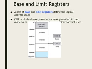
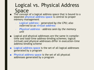
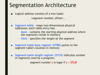
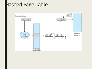
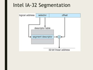
Silberschatz, Galvin and Gagne ©2013
Operating System Concepts – 9th Edition
Chapter 8: Main Memory
P. Indhuja MCA., M.PHIL.,
Chapter 8: Memory Management
■ Background
■ Swapping
■ Contiguous Memory Allocation
■ Segmentation
■ Paging
■ Structure of the Page Table
■ Example: The Intel 32 and 64-bit Architectures
■ Example: ARM Architecture
Objectives
■ To provide a detailed description of various ways of
organizing memory hardware
■ To discuss various memory-management techniques,
including paging and segmentation
■ To provide a detailed description of the Intel
Pentium, which supports both pure segmentation
and segmentation with paging
Background
■ Program must be brought (from disk) into memory
and placed within a process for it to be run
■ Main memory and registers are only storage CPU can
access directly
■ Memory unit only sees a stream of addresses + read
requests, or address + data and write requests
■ Register access in one CPU clock (or less)
■ Main memory can take many cycles, causing a stall
■ Cache sits between main memory and CPU registers
■ Protection of memory required to ensure correct
operation
Base and Limit Registers
■ A pair of base and limit registers define the logical
address space
■ CPU must check every memory access generated in user
mode to be sure it is between base and limit for that user
Hardware Address Protection
Address Binding
■ Programs on disk, ready to be brought into memory to execute form an
input queue
– Without support, must be loaded into address 0000
■ Inconvenient to have first user process physical address always at 0000
– How can it not be?
■ Further, addresses represented in different ways at different stages of a
program’s life
– Source code addresses usually symbolic
– Compiled code addresses bind to relocatable addresses
■ i.e. “14 bytes from beginning of this module”
– Linker or loader will bind relocatable addresses to absolute
addresses
■ i.e. 74014
– Each binding maps one address space to another
Binding of Instructions and Data to Memory
■ Address binding of instructions and data to memory
addresses can happen at three different stages
– Compile time: If memory location known a priori,
absolute code can be generated; must recompile
code if starting location changes
– Load time: Must generate relocatable code if
memory location is not known at compile time
– Execution time: Binding delayed until run time if
the process can be moved during its execution from
one memory segment to another
■ Need hardware support for address maps (e.g., base
and limit registers)
Multistep Processing of a User Program
Logical vs. Physical Address
Space
■ The concept of a logical address space that is bound to a
separate physical address space is central to proper
memory management
– Logical address – generated by the CPU; also
referred to as virtual address
– Physical address – address seen by the memory
unit
■ Logical and physical addresses are the same in compile-
time and load-time address-binding schemes; logical
(virtual) and physical addresses differ in execution-time
address-binding scheme
■ Logical address space is the set of all logical addresses
generated by a program
■ Physical address space is the set of all physical
addresses generated by a program
Memory-Management Unit (MMU)
■ Hardware device that at run time maps virtual to
physical address
■ Many methods possible, covered in the rest of this
chapter
■ To start, consider simple scheme where the value in the
relocation register is added to every address generated
by a user process at the time it is sent to memory
– Base register now called relocation register
– MS-DOS on Intel 80x86 used 4 relocation registers
■ The user program deals with logical addresses; it never
sees the real physical addresses
– Execution-time binding occurs when reference is
made to location in memory
– Logical address bound to physical addresses
Dynamic relocation using a relocation register
 Routine is not loaded until it is
called
 Better memory-space utilization;
unused routine is never loaded
 All routines kept on disk in
relocatable load format
 Useful when large amounts of
code are needed to handle
infrequently occurring cases
 No special support from the
operating system is required
 Implemented through program
design
 OS can help by providing libraries
to implement dynamic loading
Dynamic Linking
■ Static linking – system libraries and program code
combined by the loader into the binary program image
■ Dynamic linking –linking postponed until execution time
■ Small piece of code, stub, used to locate the appropriate
memory-resident library routine
■ Stub replaces itself with the address of the routine, and
executes the routine
■ Operating system checks if routine is in processes’ memory
address
– If not in address space, add to address space
■ Dynamic linking is particularly useful for libraries
■ System also known as shared libraries
■ Consider applicability to patching system libraries
– Versioning may be needed
Swapping
■ A process can be swapped temporarily out of memory to
a backing store, and then brought back into memory for
continued execution
– Total physical memory space of processes can
exceed physical memory
■ Backing store – fast disk large enough to accommodate
copies of all memory images for all users; must provide
direct access to these memory images
■ Roll out, roll in – swapping variant used for priority-
based scheduling algorithms; lower-priority process is
swapped out so higher-priority process can be loaded
and executed
■ Major part of swap time is transfer time; total transfer
time is directly proportional to the amount of memory
swapped
■ System maintains a ready queue of ready-to-run
processes which have memory images on disk
Swapping (Cont.)
■ Does the swapped out process need to swap back in to
same physical addresses?
■ Depends on address binding method
– Plus consider pending I/O to / from process memory
space
■ Modified versions of swapping are found on many systems
(i.e., UNIX, Linux, and Windows)
– Swapping normally disabled
– Started if more than threshold amount of memory
allocated
– Disabled again once memory demand reduced below
threshold
Schematic View of Swapping
Context Switch Time including Swapping
■ If next processes to be put on CPU is not in memory,
need to swap out a process and swap in target process
■ Context switch time can then be very high
■ 100MB process swapping to hard disk with transfer rate
of 50MB/sec
– Swap out time of 2000 ms
– Plus swap in of same sized process
– Total context switch swapping component time of
4000ms (4 seconds)
■ Can reduce if reduce size of memory swapped – by
knowing how much memory really being used
– System calls to inform OS of memory use via
request_memory() and release_memory()
Context Switch Time and Swapping (Cont.)
■ Other constraints as well on swapping
– Pending I/O – can’t swap out as I/O would occur to
wrong process
– Or always transfer I/O to kernel space, then to I/O
device
■ Known as double buffering, adds overhead
■ Standard swapping not used in modern operating systems
– But modified version common
■ Swap only when free memory extremely low
Swapping on Mobile Systems
■ Not typically supported
– Flash memory based
■ Small amount of space
■ Limited number of write cycles
■ Poor throughput between flash memory and CPU on mobile
platform
■ Instead use other methods to free memory if low
– iOS asks apps to voluntarily relinquish allocated memory
■ Read-only data thrown out and reloaded from flash if
needed
■ Failure to free can result in termination
– Android terminates apps if low free memory, but first
writes application state to flash for fast restart
– Both OSes support paging as discussed below
Contiguous Allocation
■ Main memory must support both OS and user processes
■ Limited resource, must allocate efficiently
■ Contiguous allocation is one early method
■ Main memory usually into two partitions:
– Resident operating system, usually held in low
memory with interrupt vector
– User processes then held in high memory
– Each process contained in single contiguous section
of memory
Contiguous Allocation (Cont.)
■ Relocation registers used to protect user processes from
each other, and from changing operating-system code and
data
– Base register contains value of smallest physical
address
– Limit register contains range of logical addresses –
each logical address must be less than the limit
register
– MMU maps logical address dynamically
– Can then allow actions such as kernel code being
transient and kernel changing size
Hardware Support for Relocation and Limit Registers
Multiple-partition allocation
■ Multiple-partition allocation
– Degree of multiprogramming limited by number of partitions
– Variable-partition sizes for efficiency (sized to a given process’ needs)
– Hole – block of available memory; holes of various size are scattered
throughout memory
– When a process arrives, it is allocated memory from a hole large
enough to accommodate it
– Process exiting frees its partition, adjacent free partitions combined
– Operating system maintains information about:
a) allocated partitions b) free partitions (hole)
Dynamic Storage-Allocation
Problem
■ First-fit: Allocate the first hole that is big enough
■ Best-fit: Allocate the smallest hole that is big enough;
must search entire list, unless ordered by size
– Produces the smallest leftover hole
■ Worst-fit: Allocate the largest hole; must also search
entire list
– Produces the largest leftover hole
How to satisfy a request of size n from a list of free holes?
First-fit and best-fit better than worst-fit in terms of speed and storage
utilization
Fragmentation
■ External Fragmentation – total memory space exists
to satisfy a request, but it is not contiguous
■ Internal Fragmentation – allocated memory may be
slightly larger than requested memory; this size
difference is memory internal to a partition, but not
being used
■ First fit analysis reveals that given N blocks allocated,
0.5 N blocks lost to fragmentation
– 1/3 may be unusable -> 50-percent rule
Fragmentation (Cont.)
■ Reduce external fragmentation by compaction
– Shuffle memory contents to place all free memory
together in one large block
– Compaction is possible only if relocation is
dynamic, and is done at execution time
– I/O problem
■ Latch job in memory while it is involved in I/O
■ Do I/O only into OS buffers
■ Now consider that backing store has same
fragmentation problems
Segmentation
■ Memory-management scheme that supports user view of memory
■ A program is a collection of segments
– A segment is a logical unit such as:
main program
procedure
function
method
object
local variables, global variables
common block
stack
symbol table
arrays
User’s View of a Program
Logical View of Segmentation
1
3
2
4
1
4
2
3
user space physical memory space
Segmentation Architecture
■ Logical address consists of a two tuple:
<segment-number, offset>,
■ Segment table – maps two-dimensional physical
addresses; each table entry has:
– base – contains the starting physical address where
the segments reside in memory
– limit – specifies the length of the segment
■ Segment-table base register (STBR) points to the
segment table’s location in memory
■ Segment-table length register (STLR) indicates number
of segments used by a program;
segment number s is legal if s < STLR
Segmentation Architecture
(Cont.)
■ Protection
– With each entry in segment table associate:
■ validation bit = 0  illegal segment
■ read/write/execute privileges
■ Protection bits associated with segments; code
sharing occurs at segment level
■ Since segments vary in length, memory allocation is a
dynamic storage-allocation problem
■ A segmentation example is shown in the following
diagram
Segmentation Hardware
Paging
■ Physical address space of a process can be noncontiguous;
process is allocated physical memory whenever the latter is
available
– Avoids external fragmentation
– Avoids problem of varying sized memory chunks
■ Divide physical memory into fixed-sized blocks called
frames
– Size is power of 2, between 512 bytes and 16 Mbytes
■ Divide logical memory into blocks of same size called pages
■ Keep track of all free frames
■ To run a program of size N pages, need to find N free frames
and load program
■ Set up a page table to translate logical to physical
addresses
■ Backing store likewise split into pages
■ Still have Internal fragmentation
Address Translation Scheme
■ Address generated by CPU is divided into:
– Page number (p) – used as an index into a page table
which contains base address of each page in physical
memory
– Page offset (d) – combined with base address to
define the physical memory address that is sent to
the memory unit
– For given logical address space 2m and page size 2n
page number page offset
p d
m -n n
Paging Hardware
Paging Model of Logical and Physical Memory
Paging Example
n=2 and m=4 32-byte memory and 4-byte pages
Paging (Cont.)
■ Calculating internal fragmentation
– Page size = 2,048 bytes
– Process size = 72,766 bytes
– 35 pages + 1,086 bytes
– Internal fragmentation of 2,048 - 1,086 = 962 bytes
– Worst case fragmentation = 1 frame – 1 byte
– On average fragmentation = 1 / 2 frame size
– So small frame sizes desirable?
– But each page table entry takes memory to track
– Page sizes growing over time
■ Solaris supports two page sizes – 8 KB and 4 MB
■ Process view and physical memory now very different
■ By implementation process can only access its own memory
Free Frames
Before allocation After allocation
Implementation of Page Table
■ Page table is kept in main memory
■ Page-table base register (PTBR) points to the page
table
■ Page-table length register (PTLR) indicates size of
the page table
■ In this scheme every data/instruction access requires
two memory accesses
– One for the page table and one for the data /
instruction
■ The two memory access problem can be solved by the
use of a special fast-lookup hardware cache called
associative memory or translation look-aside buffers
(TLBs)
Implementation of Page Table
(Cont.)
■ Some TLBs store address-space identifiers (ASIDs) in
each TLB entry – uniquely identifies each process to
provide address-space protection for that process
– Otherwise need to flush at every context switch
■ TLBs typically small (64 to 1,024 entries)
■ On a TLB miss, value is loaded into the TLB for faster
access next time
– Replacement policies must be considered
– Some entries can be wired down for permanent
fast access
Associative Memory
■ Associative memory – parallel search
■ Address translation (p, d)
– If p is in associative register, get frame # out
– Otherwise get frame # from page table in memory
Page # Frame #
Paging Hardware With TLB
Effective Access Time
■ Associative Lookup =  time unit
– Can be < 10% of memory access time
■ Hit ratio = 
– Hit ratio – percentage of times that a page number is found
in the associative registers; ratio related to number of
associative registers
■ Consider  = 80%,  = 20ns for TLB search, 100ns for memory
access
■ Effective Access Time (EAT)
EAT = (1 + )  + (2 + )(1 – )
= 2 +  – 
■ Consider  = 80%,  = 20ns for TLB search, 100ns for memory
access
– EAT = 0.80 x 100 + 0.20 x 200 = 120ns
■ Consider more realistic hit ratio ->  = 99%,  = 20ns for TLB
search, 100ns for memory access
– EAT = 0.99 x 100 + 0.01 x 200 = 101ns
Memory Protection
■ Memory protection implemented by associating
protection bit with each frame to indicate if read-only
or read-write access is allowed
– Can also add more bits to indicate page execute-
only, and so on
■ Valid-invalid bit attached to each entry in the page
table:
– “valid” indicates that the associated page is in the
process’ logical address space, and is thus a legal
page
– “invalid” indicates that the page is not in the
process’ logical address space
– Or use page-table length register (PTLR)
■ Any violations result in a trap to the kernel
Valid (v) or Invalid (i) Bit In A Page Table
Shared Pages
■ Shared code
– One copy of read-only (reentrant) code shared
among processes (i.e., text editors, compilers,
window systems)
– Similar to multiple threads sharing the same
process space
– Also useful for interprocess communication if
sharing of read-write pages is allowed
■ Private code and data
– Each process keeps a separate copy of the code
and data
– The pages for the private code and data can
appear anywhere in the logical address space
Shared Pages Example
Structure of the Page Table
■ Memory structures for paging can get huge using
straight-forward methods
– Consider a 32-bit logical address space as on
modern computers
– Page size of 4 KB (212)
– Page table would have 1 million entries (232 / 212)
– If each entry is 4 bytes -> 4 MB of physical address
space / memory for page table alone
■ That amount of memory used to cost a lot
■ Don’t want to allocate that contiguously in main
memory
■ Hierarchical Paging
■ Hashed Page Tables
■ Inverted Page Tables
Hierarchical Page Tables
■ Break up the logical address space into
multiple page tables
■ A simple technique is a two-level page table
■ We then page the page table
Two-Level Page-Table Scheme
Two-Level Paging Example
■ A logical address (on 32-bit machine with 1K page size) is divided
into:
– a page number consisting of 22 bits
– a page offset consisting of 10 bits
■ Since the page table is paged, the page number is further divided
into:
– a 12-bit page number
– a 10-bit page offset
■ Thus, a logical address is as follows:
■ where p1 is an index into the outer page table, and p2 is the
displacement within the page of the inner page table
■ Known as forward-mapped page table
Address-Translation Scheme
64-bit Logical Address Space
■ Even two-level paging scheme not sufficient
■ If page size is 4 KB (212)
– Then page table has 252 entries
– If two level scheme, inner page tables could be 210 4-byte
entries
– Address would look like
– Outer page table has 242 entries or 244 bytes
– One solution is to add a 2nd outer page table
– But in the following example the 2nd outer page table is still
234 bytes in size
■ And possibly 4 memory access to get to one physical memory
location
Three-level Paging Scheme
Hashed Page Tables
■ Common in address spaces > 32 bits
■ The virtual page number is hashed into a page table
– This page table contains a chain of elements hashing to the
same location
■ Each element contains (1) the virtual page number (2) the value
of the mapped page frame (3) a pointer to the next element
■ Virtual page numbers are compared in this chain searching for a
match
– If a match is found, the corresponding physical frame is
extracted
■ Variation for 64-bit addresses is clustered page tables
– Similar to hashed but each entry refers to several pages
(such as 16) rather than 1
– Especially useful for sparse address spaces (where memory
references are non-contiguous and scattered)
Hashed Page Table
Inverted Page Table
■ Rather than each process having a page table and keeping
track of all possible logical pages, track all physical pages
■ One entry for each real page of memory
■ Entry consists of the virtual address of the page stored in
that real memory location, with information about the
process that owns that page
■ Decreases memory needed to store each page table, but
increases time needed to search the table when a page
reference occurs
■ Use hash table to limit the search to one — or at most a
few — page-table entries
– TLB can accelerate access
■ But how to implement shared memory?
– One mapping of a virtual address to the shared
physical address
Inverted Page Table Architecture
Oracle SPARC Solaris
■ Consider modern, 64-bit operating system example with
tightly integrated HW
– Goals are efficiency, low overhead
■ Based on hashing, but more complex
■ Two hash tables
– One kernel and one for all user processes
– Each maps memory addresses from virtual to physical
memory
– Each entry represents a contiguous area of mapped
virtual memory,
■ More efficient than having a separate hash-table entry
for each page
– Each entry has base address and span (indicating the
number of pages the entry represents)
Oracle SPARC Solaris (Cont.)
■ TLB holds translation table entries (TTEs) for fast hardware
lookups
– A cache of TTEs reside in a translation storage buffer
(TSB)
■ Includes an entry per recently accessed page
■ Virtual address reference causes TLB search
– If miss, hardware walks the in-memory TSB looking for
the TTE corresponding to the address
■ If match found, the CPU copies the TSB entry into the
TLB and translation completes
■ If no match found, kernel interrupted to search the hash
table
– The kernel then creates a TTE from the appropriate
hash table and stores it in the TSB, Interrupt
handler returns control to the MMU, which
completes the address translation.
Example: The Intel 32 and 64-bit Architectures
■ Dominant industry chips
■ Pentium CPUs are 32-bit and called IA-32 architecture
■ Current Intel CPUs are 64-bit and called IA-64 architecture
■ Many variations in the chips, cover the main ideas here
Example: The Intel IA-32 Architecture
■ Supports both segmentation and segmentation with
paging
– Each segment can be 4 GB
– Up to 16 K segments per process
– Divided into two partitions
■ First partition of up to 8 K segments are private to
process (kept in local descriptor table (LDT))
■ Second partition of up to 8K segments shared among
all processes (kept in global descriptor table (GDT))
Example: The Intel IA-32 Architecture (Cont.)
■ CPU generates logical address
– Selector given to segmentation unit
■ Which produces linear addresses
– Linear address given to paging unit
■ Which generates physical address in main memory
■ Paging units form equivalent of MMU
■ Pages sizes can be 4 KB or 4 MB
Logical to Physical Address Translation in IA-32
Intel IA-32 Segmentation
Intel IA-32 Paging Architecture
Intel IA-32 Page Address
Extensions
 32-bit address limits led Intel to create page address extension (PAE),
allowing 32-bit apps access to more than 4GB of memory space
 Paging went to a 3-level scheme
 Top two bits refer to a page directory pointer table
 Page-directory and page-table entries moved to 64-bits in size
 Net effect is increasing address space to 36 bits – 64GB of physical
memory
Intel x86-64
 Current generation Intel x86 architecture
 64 bits is ginormous (> 16 exabytes)
 In practice only implement 48 bit addressing
 Page sizes of 4 KB, 2 MB, 1 GB
 Four levels of paging hierarchy
 Can also use PAE so virtual addresses are 48 bits and physical
addresses are 52 bits
Example: ARM Architecture
 Dominant mobile platform chip
(Apple iOS and Google Android
devices for example)
 Modern, energy efficient, 32-bit
CPU
 4 KB and 16 KB pages
 1 MB and 16 MB pages (termed
sections)
 One-level paging for sections, two-
level for smaller pages
 Two levels of TLBs
 Outer level has two micro
TLBs (one data, one
instruction)
 Inner is single main TLB
 First inner is checked, on
miss outers are checked,
and on miss page table
walk performed by CPU
outer page inner page offset
4-KB
or
16-KB
page
1-MB
or
16-MB
section
32 bits
Silberschatz, Galvin and Gagne ©2013
Operating System Concepts – 9th Edition
End of Chapter 8

ch8 Memory Management OS.pptx

  • 1.
    Silberschatz, Galvin andGagne ©2013 Operating System Concepts – 9th Edition Chapter 8: Main Memory P. Indhuja MCA., M.PHIL.,
  • 2.
    Chapter 8: MemoryManagement ■ Background ■ Swapping ■ Contiguous Memory Allocation ■ Segmentation ■ Paging ■ Structure of the Page Table ■ Example: The Intel 32 and 64-bit Architectures ■ Example: ARM Architecture
  • 3.
    Objectives ■ To providea detailed description of various ways of organizing memory hardware ■ To discuss various memory-management techniques, including paging and segmentation ■ To provide a detailed description of the Intel Pentium, which supports both pure segmentation and segmentation with paging
  • 4.
    Background ■ Program mustbe brought (from disk) into memory and placed within a process for it to be run ■ Main memory and registers are only storage CPU can access directly ■ Memory unit only sees a stream of addresses + read requests, or address + data and write requests ■ Register access in one CPU clock (or less) ■ Main memory can take many cycles, causing a stall ■ Cache sits between main memory and CPU registers ■ Protection of memory required to ensure correct operation
  • 5.
    Base and LimitRegisters ■ A pair of base and limit registers define the logical address space ■ CPU must check every memory access generated in user mode to be sure it is between base and limit for that user
  • 6.
  • 7.
    Address Binding ■ Programson disk, ready to be brought into memory to execute form an input queue – Without support, must be loaded into address 0000 ■ Inconvenient to have first user process physical address always at 0000 – How can it not be? ■ Further, addresses represented in different ways at different stages of a program’s life – Source code addresses usually symbolic – Compiled code addresses bind to relocatable addresses ■ i.e. “14 bytes from beginning of this module” – Linker or loader will bind relocatable addresses to absolute addresses ■ i.e. 74014 – Each binding maps one address space to another
  • 8.
    Binding of Instructionsand Data to Memory ■ Address binding of instructions and data to memory addresses can happen at three different stages – Compile time: If memory location known a priori, absolute code can be generated; must recompile code if starting location changes – Load time: Must generate relocatable code if memory location is not known at compile time – Execution time: Binding delayed until run time if the process can be moved during its execution from one memory segment to another ■ Need hardware support for address maps (e.g., base and limit registers)
  • 9.
  • 10.
    Logical vs. PhysicalAddress Space ■ The concept of a logical address space that is bound to a separate physical address space is central to proper memory management – Logical address – generated by the CPU; also referred to as virtual address – Physical address – address seen by the memory unit ■ Logical and physical addresses are the same in compile- time and load-time address-binding schemes; logical (virtual) and physical addresses differ in execution-time address-binding scheme ■ Logical address space is the set of all logical addresses generated by a program ■ Physical address space is the set of all physical addresses generated by a program
  • 11.
    Memory-Management Unit (MMU) ■Hardware device that at run time maps virtual to physical address ■ Many methods possible, covered in the rest of this chapter ■ To start, consider simple scheme where the value in the relocation register is added to every address generated by a user process at the time it is sent to memory – Base register now called relocation register – MS-DOS on Intel 80x86 used 4 relocation registers ■ The user program deals with logical addresses; it never sees the real physical addresses – Execution-time binding occurs when reference is made to location in memory – Logical address bound to physical addresses
  • 12.
    Dynamic relocation usinga relocation register  Routine is not loaded until it is called  Better memory-space utilization; unused routine is never loaded  All routines kept on disk in relocatable load format  Useful when large amounts of code are needed to handle infrequently occurring cases  No special support from the operating system is required  Implemented through program design  OS can help by providing libraries to implement dynamic loading
  • 13.
    Dynamic Linking ■ Staticlinking – system libraries and program code combined by the loader into the binary program image ■ Dynamic linking –linking postponed until execution time ■ Small piece of code, stub, used to locate the appropriate memory-resident library routine ■ Stub replaces itself with the address of the routine, and executes the routine ■ Operating system checks if routine is in processes’ memory address – If not in address space, add to address space ■ Dynamic linking is particularly useful for libraries ■ System also known as shared libraries ■ Consider applicability to patching system libraries – Versioning may be needed
  • 14.
    Swapping ■ A processcan be swapped temporarily out of memory to a backing store, and then brought back into memory for continued execution – Total physical memory space of processes can exceed physical memory ■ Backing store – fast disk large enough to accommodate copies of all memory images for all users; must provide direct access to these memory images ■ Roll out, roll in – swapping variant used for priority- based scheduling algorithms; lower-priority process is swapped out so higher-priority process can be loaded and executed ■ Major part of swap time is transfer time; total transfer time is directly proportional to the amount of memory swapped ■ System maintains a ready queue of ready-to-run processes which have memory images on disk
  • 15.
    Swapping (Cont.) ■ Doesthe swapped out process need to swap back in to same physical addresses? ■ Depends on address binding method – Plus consider pending I/O to / from process memory space ■ Modified versions of swapping are found on many systems (i.e., UNIX, Linux, and Windows) – Swapping normally disabled – Started if more than threshold amount of memory allocated – Disabled again once memory demand reduced below threshold
  • 16.
  • 17.
    Context Switch Timeincluding Swapping ■ If next processes to be put on CPU is not in memory, need to swap out a process and swap in target process ■ Context switch time can then be very high ■ 100MB process swapping to hard disk with transfer rate of 50MB/sec – Swap out time of 2000 ms – Plus swap in of same sized process – Total context switch swapping component time of 4000ms (4 seconds) ■ Can reduce if reduce size of memory swapped – by knowing how much memory really being used – System calls to inform OS of memory use via request_memory() and release_memory()
  • 18.
    Context Switch Timeand Swapping (Cont.) ■ Other constraints as well on swapping – Pending I/O – can’t swap out as I/O would occur to wrong process – Or always transfer I/O to kernel space, then to I/O device ■ Known as double buffering, adds overhead ■ Standard swapping not used in modern operating systems – But modified version common ■ Swap only when free memory extremely low
  • 19.
    Swapping on MobileSystems ■ Not typically supported – Flash memory based ■ Small amount of space ■ Limited number of write cycles ■ Poor throughput between flash memory and CPU on mobile platform ■ Instead use other methods to free memory if low – iOS asks apps to voluntarily relinquish allocated memory ■ Read-only data thrown out and reloaded from flash if needed ■ Failure to free can result in termination – Android terminates apps if low free memory, but first writes application state to flash for fast restart – Both OSes support paging as discussed below
  • 20.
    Contiguous Allocation ■ Mainmemory must support both OS and user processes ■ Limited resource, must allocate efficiently ■ Contiguous allocation is one early method ■ Main memory usually into two partitions: – Resident operating system, usually held in low memory with interrupt vector – User processes then held in high memory – Each process contained in single contiguous section of memory
  • 21.
    Contiguous Allocation (Cont.) ■Relocation registers used to protect user processes from each other, and from changing operating-system code and data – Base register contains value of smallest physical address – Limit register contains range of logical addresses – each logical address must be less than the limit register – MMU maps logical address dynamically – Can then allow actions such as kernel code being transient and kernel changing size
  • 22.
    Hardware Support forRelocation and Limit Registers
  • 23.
    Multiple-partition allocation ■ Multiple-partitionallocation – Degree of multiprogramming limited by number of partitions – Variable-partition sizes for efficiency (sized to a given process’ needs) – Hole – block of available memory; holes of various size are scattered throughout memory – When a process arrives, it is allocated memory from a hole large enough to accommodate it – Process exiting frees its partition, adjacent free partitions combined – Operating system maintains information about: a) allocated partitions b) free partitions (hole)
  • 24.
    Dynamic Storage-Allocation Problem ■ First-fit:Allocate the first hole that is big enough ■ Best-fit: Allocate the smallest hole that is big enough; must search entire list, unless ordered by size – Produces the smallest leftover hole ■ Worst-fit: Allocate the largest hole; must also search entire list – Produces the largest leftover hole How to satisfy a request of size n from a list of free holes? First-fit and best-fit better than worst-fit in terms of speed and storage utilization
  • 25.
    Fragmentation ■ External Fragmentation– total memory space exists to satisfy a request, but it is not contiguous ■ Internal Fragmentation – allocated memory may be slightly larger than requested memory; this size difference is memory internal to a partition, but not being used ■ First fit analysis reveals that given N blocks allocated, 0.5 N blocks lost to fragmentation – 1/3 may be unusable -> 50-percent rule
  • 26.
    Fragmentation (Cont.) ■ Reduceexternal fragmentation by compaction – Shuffle memory contents to place all free memory together in one large block – Compaction is possible only if relocation is dynamic, and is done at execution time – I/O problem ■ Latch job in memory while it is involved in I/O ■ Do I/O only into OS buffers ■ Now consider that backing store has same fragmentation problems
  • 27.
    Segmentation ■ Memory-management schemethat supports user view of memory ■ A program is a collection of segments – A segment is a logical unit such as: main program procedure function method object local variables, global variables common block stack symbol table arrays
  • 28.
  • 29.
    Logical View ofSegmentation 1 3 2 4 1 4 2 3 user space physical memory space
  • 30.
    Segmentation Architecture ■ Logicaladdress consists of a two tuple: <segment-number, offset>, ■ Segment table – maps two-dimensional physical addresses; each table entry has: – base – contains the starting physical address where the segments reside in memory – limit – specifies the length of the segment ■ Segment-table base register (STBR) points to the segment table’s location in memory ■ Segment-table length register (STLR) indicates number of segments used by a program; segment number s is legal if s < STLR
  • 31.
    Segmentation Architecture (Cont.) ■ Protection –With each entry in segment table associate: ■ validation bit = 0  illegal segment ■ read/write/execute privileges ■ Protection bits associated with segments; code sharing occurs at segment level ■ Since segments vary in length, memory allocation is a dynamic storage-allocation problem ■ A segmentation example is shown in the following diagram
  • 32.
  • 33.
    Paging ■ Physical addressspace of a process can be noncontiguous; process is allocated physical memory whenever the latter is available – Avoids external fragmentation – Avoids problem of varying sized memory chunks ■ Divide physical memory into fixed-sized blocks called frames – Size is power of 2, between 512 bytes and 16 Mbytes ■ Divide logical memory into blocks of same size called pages ■ Keep track of all free frames ■ To run a program of size N pages, need to find N free frames and load program ■ Set up a page table to translate logical to physical addresses ■ Backing store likewise split into pages ■ Still have Internal fragmentation
  • 34.
    Address Translation Scheme ■Address generated by CPU is divided into: – Page number (p) – used as an index into a page table which contains base address of each page in physical memory – Page offset (d) – combined with base address to define the physical memory address that is sent to the memory unit – For given logical address space 2m and page size 2n page number page offset p d m -n n
  • 35.
  • 36.
    Paging Model ofLogical and Physical Memory
  • 37.
    Paging Example n=2 andm=4 32-byte memory and 4-byte pages
  • 38.
    Paging (Cont.) ■ Calculatinginternal fragmentation – Page size = 2,048 bytes – Process size = 72,766 bytes – 35 pages + 1,086 bytes – Internal fragmentation of 2,048 - 1,086 = 962 bytes – Worst case fragmentation = 1 frame – 1 byte – On average fragmentation = 1 / 2 frame size – So small frame sizes desirable? – But each page table entry takes memory to track – Page sizes growing over time ■ Solaris supports two page sizes – 8 KB and 4 MB ■ Process view and physical memory now very different ■ By implementation process can only access its own memory
  • 39.
  • 40.
    Implementation of PageTable ■ Page table is kept in main memory ■ Page-table base register (PTBR) points to the page table ■ Page-table length register (PTLR) indicates size of the page table ■ In this scheme every data/instruction access requires two memory accesses – One for the page table and one for the data / instruction ■ The two memory access problem can be solved by the use of a special fast-lookup hardware cache called associative memory or translation look-aside buffers (TLBs)
  • 41.
    Implementation of PageTable (Cont.) ■ Some TLBs store address-space identifiers (ASIDs) in each TLB entry – uniquely identifies each process to provide address-space protection for that process – Otherwise need to flush at every context switch ■ TLBs typically small (64 to 1,024 entries) ■ On a TLB miss, value is loaded into the TLB for faster access next time – Replacement policies must be considered – Some entries can be wired down for permanent fast access
  • 42.
    Associative Memory ■ Associativememory – parallel search ■ Address translation (p, d) – If p is in associative register, get frame # out – Otherwise get frame # from page table in memory Page # Frame #
  • 43.
  • 44.
    Effective Access Time ■Associative Lookup =  time unit – Can be < 10% of memory access time ■ Hit ratio =  – Hit ratio – percentage of times that a page number is found in the associative registers; ratio related to number of associative registers ■ Consider  = 80%,  = 20ns for TLB search, 100ns for memory access ■ Effective Access Time (EAT) EAT = (1 + )  + (2 + )(1 – ) = 2 +  –  ■ Consider  = 80%,  = 20ns for TLB search, 100ns for memory access – EAT = 0.80 x 100 + 0.20 x 200 = 120ns ■ Consider more realistic hit ratio ->  = 99%,  = 20ns for TLB search, 100ns for memory access – EAT = 0.99 x 100 + 0.01 x 200 = 101ns
  • 45.
    Memory Protection ■ Memoryprotection implemented by associating protection bit with each frame to indicate if read-only or read-write access is allowed – Can also add more bits to indicate page execute- only, and so on ■ Valid-invalid bit attached to each entry in the page table: – “valid” indicates that the associated page is in the process’ logical address space, and is thus a legal page – “invalid” indicates that the page is not in the process’ logical address space – Or use page-table length register (PTLR) ■ Any violations result in a trap to the kernel
  • 46.
    Valid (v) orInvalid (i) Bit In A Page Table
  • 47.
    Shared Pages ■ Sharedcode – One copy of read-only (reentrant) code shared among processes (i.e., text editors, compilers, window systems) – Similar to multiple threads sharing the same process space – Also useful for interprocess communication if sharing of read-write pages is allowed ■ Private code and data – Each process keeps a separate copy of the code and data – The pages for the private code and data can appear anywhere in the logical address space
  • 48.
  • 49.
    Structure of thePage Table ■ Memory structures for paging can get huge using straight-forward methods – Consider a 32-bit logical address space as on modern computers – Page size of 4 KB (212) – Page table would have 1 million entries (232 / 212) – If each entry is 4 bytes -> 4 MB of physical address space / memory for page table alone ■ That amount of memory used to cost a lot ■ Don’t want to allocate that contiguously in main memory ■ Hierarchical Paging ■ Hashed Page Tables ■ Inverted Page Tables
  • 50.
    Hierarchical Page Tables ■Break up the logical address space into multiple page tables ■ A simple technique is a two-level page table ■ We then page the page table
  • 51.
  • 52.
    Two-Level Paging Example ■A logical address (on 32-bit machine with 1K page size) is divided into: – a page number consisting of 22 bits – a page offset consisting of 10 bits ■ Since the page table is paged, the page number is further divided into: – a 12-bit page number – a 10-bit page offset ■ Thus, a logical address is as follows: ■ where p1 is an index into the outer page table, and p2 is the displacement within the page of the inner page table ■ Known as forward-mapped page table
  • 53.
  • 54.
    64-bit Logical AddressSpace ■ Even two-level paging scheme not sufficient ■ If page size is 4 KB (212) – Then page table has 252 entries – If two level scheme, inner page tables could be 210 4-byte entries – Address would look like – Outer page table has 242 entries or 244 bytes – One solution is to add a 2nd outer page table – But in the following example the 2nd outer page table is still 234 bytes in size ■ And possibly 4 memory access to get to one physical memory location
  • 55.
  • 56.
    Hashed Page Tables ■Common in address spaces > 32 bits ■ The virtual page number is hashed into a page table – This page table contains a chain of elements hashing to the same location ■ Each element contains (1) the virtual page number (2) the value of the mapped page frame (3) a pointer to the next element ■ Virtual page numbers are compared in this chain searching for a match – If a match is found, the corresponding physical frame is extracted ■ Variation for 64-bit addresses is clustered page tables – Similar to hashed but each entry refers to several pages (such as 16) rather than 1 – Especially useful for sparse address spaces (where memory references are non-contiguous and scattered)
  • 57.
  • 58.
    Inverted Page Table ■Rather than each process having a page table and keeping track of all possible logical pages, track all physical pages ■ One entry for each real page of memory ■ Entry consists of the virtual address of the page stored in that real memory location, with information about the process that owns that page ■ Decreases memory needed to store each page table, but increases time needed to search the table when a page reference occurs ■ Use hash table to limit the search to one — or at most a few — page-table entries – TLB can accelerate access ■ But how to implement shared memory? – One mapping of a virtual address to the shared physical address
  • 59.
    Inverted Page TableArchitecture
  • 60.
    Oracle SPARC Solaris ■Consider modern, 64-bit operating system example with tightly integrated HW – Goals are efficiency, low overhead ■ Based on hashing, but more complex ■ Two hash tables – One kernel and one for all user processes – Each maps memory addresses from virtual to physical memory – Each entry represents a contiguous area of mapped virtual memory, ■ More efficient than having a separate hash-table entry for each page – Each entry has base address and span (indicating the number of pages the entry represents)
  • 61.
    Oracle SPARC Solaris(Cont.) ■ TLB holds translation table entries (TTEs) for fast hardware lookups – A cache of TTEs reside in a translation storage buffer (TSB) ■ Includes an entry per recently accessed page ■ Virtual address reference causes TLB search – If miss, hardware walks the in-memory TSB looking for the TTE corresponding to the address ■ If match found, the CPU copies the TSB entry into the TLB and translation completes ■ If no match found, kernel interrupted to search the hash table – The kernel then creates a TTE from the appropriate hash table and stores it in the TSB, Interrupt handler returns control to the MMU, which completes the address translation.
  • 62.
    Example: The Intel32 and 64-bit Architectures ■ Dominant industry chips ■ Pentium CPUs are 32-bit and called IA-32 architecture ■ Current Intel CPUs are 64-bit and called IA-64 architecture ■ Many variations in the chips, cover the main ideas here
  • 63.
    Example: The IntelIA-32 Architecture ■ Supports both segmentation and segmentation with paging – Each segment can be 4 GB – Up to 16 K segments per process – Divided into two partitions ■ First partition of up to 8 K segments are private to process (kept in local descriptor table (LDT)) ■ Second partition of up to 8K segments shared among all processes (kept in global descriptor table (GDT))
  • 64.
    Example: The IntelIA-32 Architecture (Cont.) ■ CPU generates logical address – Selector given to segmentation unit ■ Which produces linear addresses – Linear address given to paging unit ■ Which generates physical address in main memory ■ Paging units form equivalent of MMU ■ Pages sizes can be 4 KB or 4 MB
  • 65.
    Logical to PhysicalAddress Translation in IA-32
  • 66.
  • 67.
    Intel IA-32 PagingArchitecture
  • 68.
    Intel IA-32 PageAddress Extensions  32-bit address limits led Intel to create page address extension (PAE), allowing 32-bit apps access to more than 4GB of memory space  Paging went to a 3-level scheme  Top two bits refer to a page directory pointer table  Page-directory and page-table entries moved to 64-bits in size  Net effect is increasing address space to 36 bits – 64GB of physical memory
  • 69.
    Intel x86-64  Currentgeneration Intel x86 architecture  64 bits is ginormous (> 16 exabytes)  In practice only implement 48 bit addressing  Page sizes of 4 KB, 2 MB, 1 GB  Four levels of paging hierarchy  Can also use PAE so virtual addresses are 48 bits and physical addresses are 52 bits
  • 70.
    Example: ARM Architecture Dominant mobile platform chip (Apple iOS and Google Android devices for example)  Modern, energy efficient, 32-bit CPU  4 KB and 16 KB pages  1 MB and 16 MB pages (termed sections)  One-level paging for sections, two- level for smaller pages  Two levels of TLBs  Outer level has two micro TLBs (one data, one instruction)  Inner is single main TLB  First inner is checked, on miss outers are checked, and on miss page table walk performed by CPU outer page inner page offset 4-KB or 16-KB page 1-MB or 16-MB section 32 bits
  • 71.
    Silberschatz, Galvin andGagne ©2013 Operating System Concepts – 9th Edition End of Chapter 8