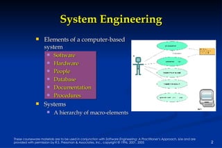
Software Engineering: A Practitioner’s Approach, 6/e Chapter 6 System Engineering copyright © 1996, 2001, 2005 R.S. Pressman & Associates, Inc. For University Use Only May be reproduced ONLY for student use at the university level when used in conjunction with  Software Engineering: A Practitioner's Approach. Any other reproduction or use is expressly prohibited.
System Engineering Elements of a computer-based system Software Hardware People Database Documentation Procedures Systems A hierarchy of macro-elements
The Hierarchy
System Modeling define the processes that serve the needs of the view under consideration. represent the behavior of the processes and the assumptions on which the behavior is based. explicitly define both exogenous and endogenous input to the model. exogenous inputs link one constituent of a given view with other constituents at the same level of other levels; endogenous input links individual components of a constituent at a particular view. represent all linkages (including output) that will enable the engineer to better understand the view.
Business Process Engineering uses an integrated set of procedures, methods, and tools to identify how information systems can best meet the strategic goals of an enterprise focuses first on the enterprise and then on the business area creates enterprise models, data models and process models creates a framework for better information management distribution, and control
UModel™ 2005 supports packages, component diagrams, and deployment diagrams to help you conveniently design, organize, and document your project architecture.  http://www.altova.com/features_other_diagrams.html   http://www.altova.com/download_umodel.html
System Architectures Three different architectures must be analyzed and designed within the context of business objectives and goals: data architecture applications architecture technology infrastructure data architecture  provides a framework for the information needs of a business or business function application architecture  encompasses those elements of a system that transform objects within the data architecture for some business purpose technology infrastructure  provides the foundation for the data and application architectures


The BPE Hierarchy Information strategy planning (ISP) strategic goals defined success factors/business rules identified enterprise model created Business area analysis (BAA) processes/services modeled interrelationships of processes and data Application Engineering a.k.a ... software engineering modeling applications/procedures that address (BAA) and constraints of ISP Construction and delivery using CASE and 4GTs, testing
 
Information Strategy Planning Management issues define strategic business goals/objectives isolate critical success factors conduct analysis of technology impact perform analysis of strategic systems Technical issues create a top-level data model cluster by business/organizational area refine model and clustering
Defining Objectives and Goals Objective —general statement of direction Goal —defines measurable objective: “reduce manufactured cost of our product” Subgoals : decrease reject rate by 20% in first 6 months gain 10% price concessions from suppliers re-engineer 30% of components for ease of manufacture during first year Objectives tend to be strategic while goals tend to be tactical
Business Area Analysis define “naturally cohesive groupings of business functions and data” (Martin) perform many of the same activities as ISP, but narrow scope to individual business area identify existing (old) information systems / determine compatibility with new ISP model define systems that are problematic  defining systems that are incompatible with new information model begin to establish  re-engineering priorities
The BAA Process sales acct manufacturing QC eng’ring distribution admin. Data Model Process Decomposition Diagram Matrices e.g., entity/process matrix Process  Flow Models
Product Engineering
Product Architecture Template
Architecture Flow Diagram
System Modeling with UML Deployment diagrams Each 3-D box depicts a hardware element that is part of the physical architecture of the system Activity diagrams Represent procedural aspects of a system element Class diagrams Represent system level elements in terms of the data that describe the element and the operations that manipulate the data These and other UML models will be discussed later
Deployment Diagram
Activity Diagram
Class Diagram

Ch06

  • 1.
    Software Engineering: APractitioner’s Approach, 6/e Chapter 6 System Engineering copyright © 1996, 2001, 2005 R.S. Pressman & Associates, Inc. For University Use Only May be reproduced ONLY for student use at the university level when used in conjunction with Software Engineering: A Practitioner's Approach. Any other reproduction or use is expressly prohibited.
  • 2.
    System Engineering Elementsof a computer-based system Software Hardware People Database Documentation Procedures Systems A hierarchy of macro-elements
  • 3.
  • 4.
    System Modeling definethe processes that serve the needs of the view under consideration. represent the behavior of the processes and the assumptions on which the behavior is based. explicitly define both exogenous and endogenous input to the model. exogenous inputs link one constituent of a given view with other constituents at the same level of other levels; endogenous input links individual components of a constituent at a particular view. represent all linkages (including output) that will enable the engineer to better understand the view.
  • 5.
    Business Process Engineeringuses an integrated set of procedures, methods, and tools to identify how information systems can best meet the strategic goals of an enterprise focuses first on the enterprise and then on the business area creates enterprise models, data models and process models creates a framework for better information management distribution, and control
  • 6.
    UModel™ 2005 supportspackages, component diagrams, and deployment diagrams to help you conveniently design, organize, and document your project architecture. http://www.altova.com/features_other_diagrams.html http://www.altova.com/download_umodel.html
  • 7.
    System Architectures Threedifferent architectures must be analyzed and designed within the context of business objectives and goals: data architecture applications architecture technology infrastructure data architecture provides a framework for the information needs of a business or business function application architecture encompasses those elements of a system that transform objects within the data architecture for some business purpose technology infrastructure provides the foundation for the data and application architectures
  • 8.
  • 9.
  • 10.
  • 11.
  • 12.
    The BPE HierarchyInformation strategy planning (ISP) strategic goals defined success factors/business rules identified enterprise model created Business area analysis (BAA) processes/services modeled interrelationships of processes and data Application Engineering a.k.a ... software engineering modeling applications/procedures that address (BAA) and constraints of ISP Construction and delivery using CASE and 4GTs, testing
  • 13.
  • 14.
    Information Strategy PlanningManagement issues define strategic business goals/objectives isolate critical success factors conduct analysis of technology impact perform analysis of strategic systems Technical issues create a top-level data model cluster by business/organizational area refine model and clustering
  • 15.
    Defining Objectives andGoals Objective —general statement of direction Goal —defines measurable objective: “reduce manufactured cost of our product” Subgoals : decrease reject rate by 20% in first 6 months gain 10% price concessions from suppliers re-engineer 30% of components for ease of manufacture during first year Objectives tend to be strategic while goals tend to be tactical
  • 16.
    Business Area Analysisdefine “naturally cohesive groupings of business functions and data” (Martin) perform many of the same activities as ISP, but narrow scope to individual business area identify existing (old) information systems / determine compatibility with new ISP model define systems that are problematic defining systems that are incompatible with new information model begin to establish re-engineering priorities
  • 17.
    The BAA Processsales acct manufacturing QC eng’ring distribution admin. Data Model Process Decomposition Diagram Matrices e.g., entity/process matrix Process Flow Models
  • 18.
  • 19.
  • 20.
  • 21.
    System Modeling withUML Deployment diagrams Each 3-D box depicts a hardware element that is part of the physical architecture of the system Activity diagrams Represent procedural aspects of a system element Class diagrams Represent system level elements in terms of the data that describe the element and the operations that manipulate the data These and other UML models will be discussed later
  • 22.
  • 23.
  • 24.