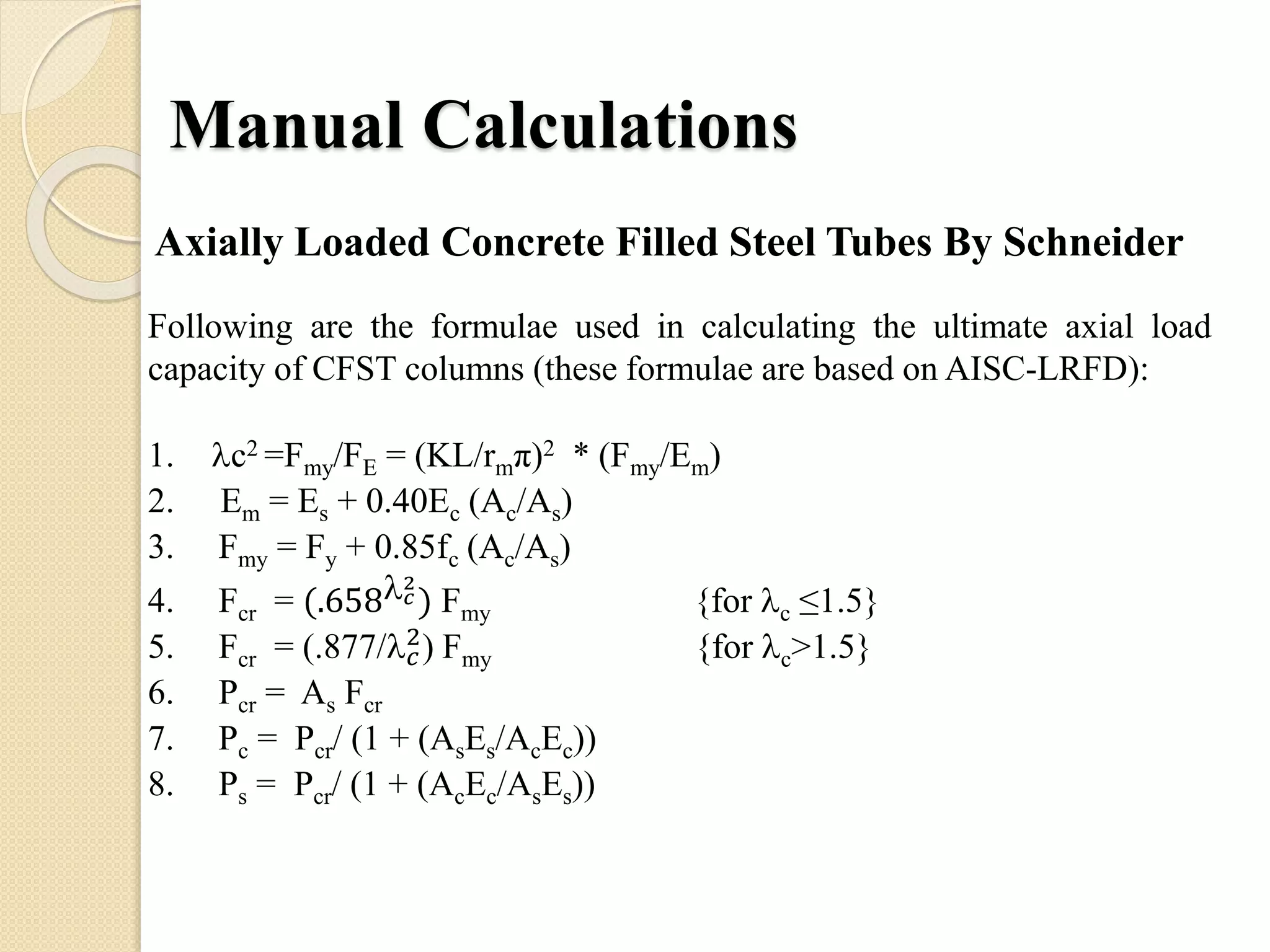
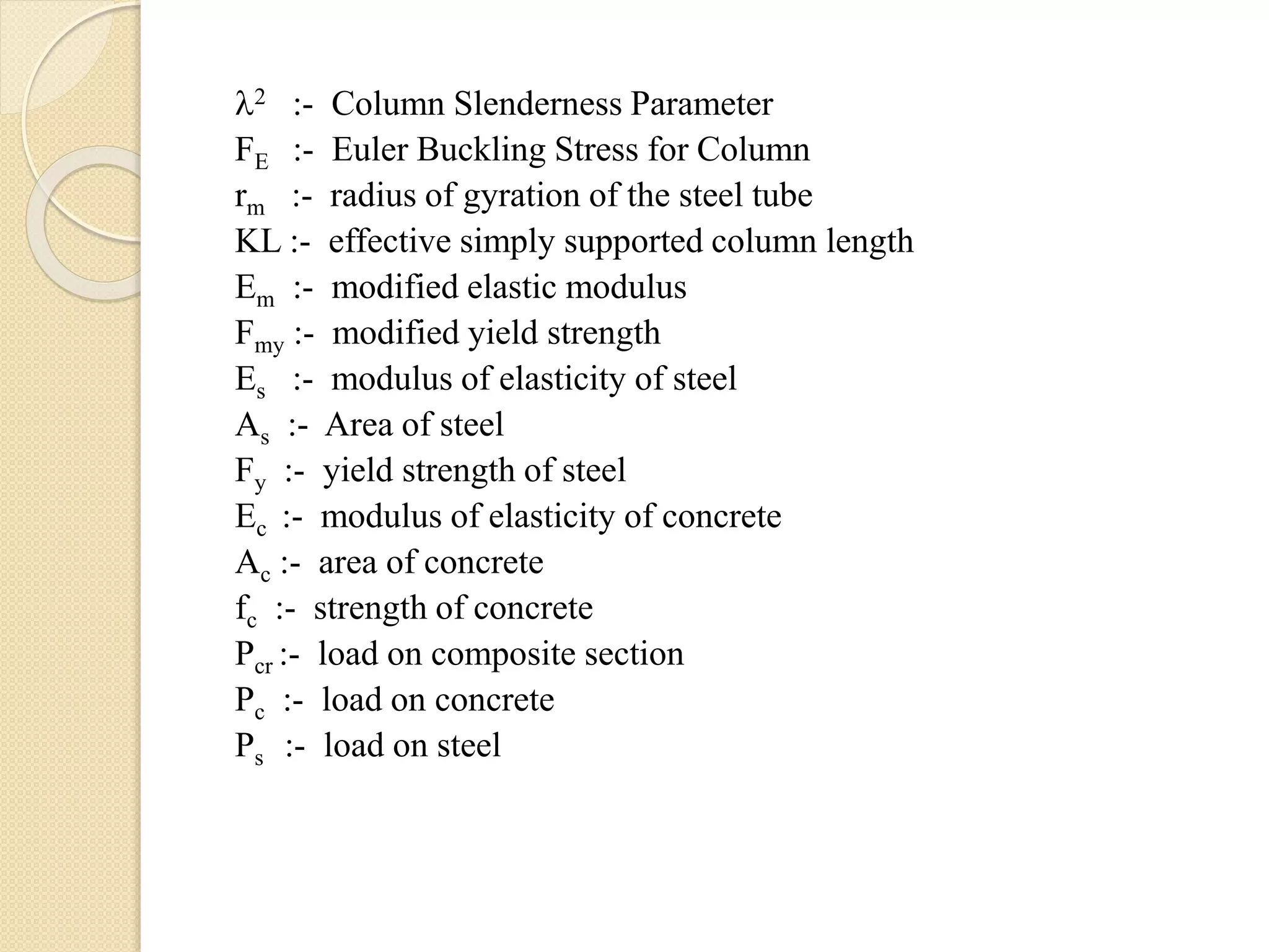
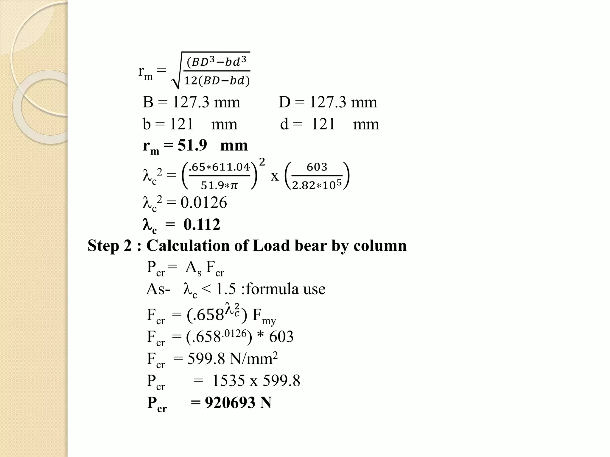
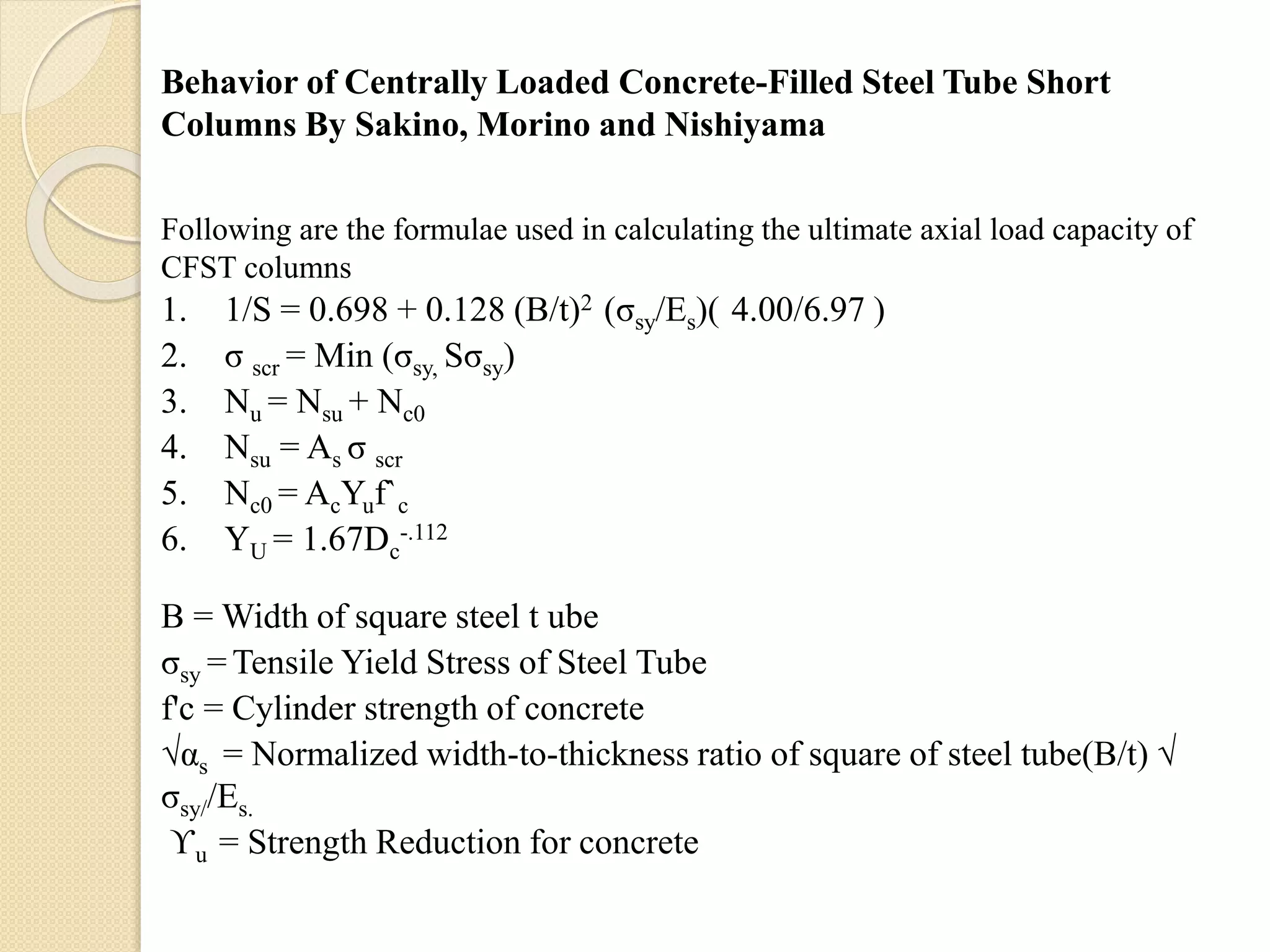
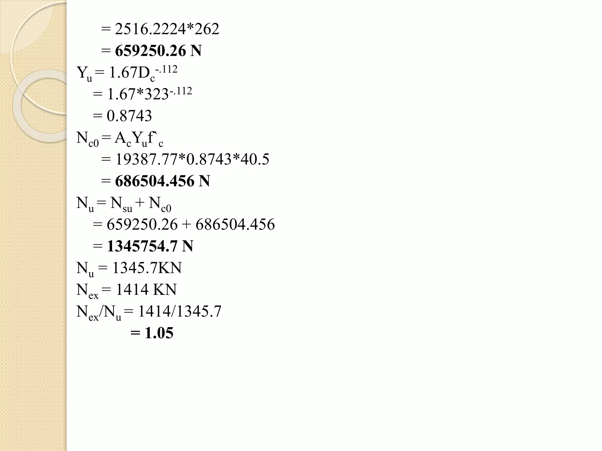
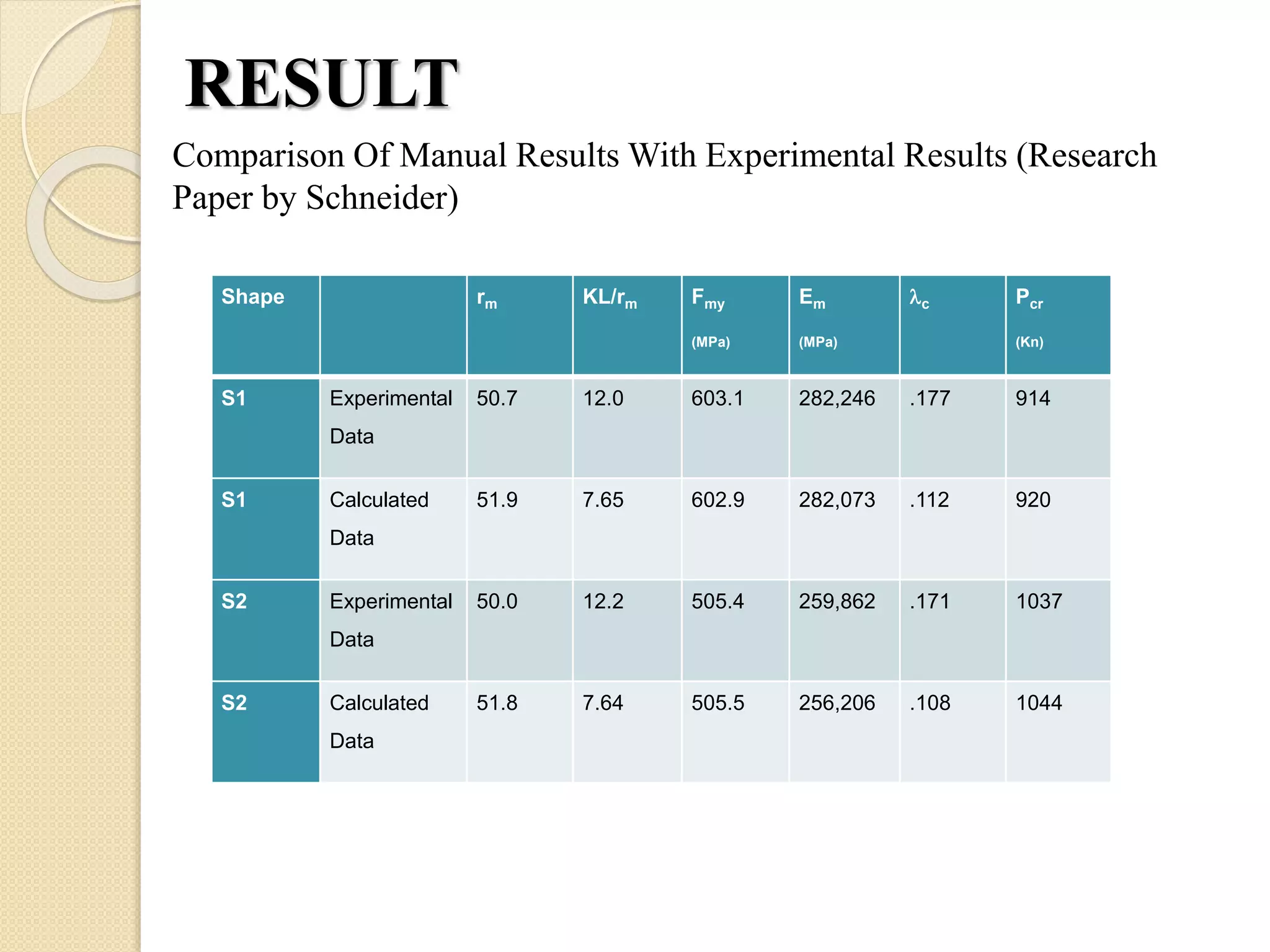
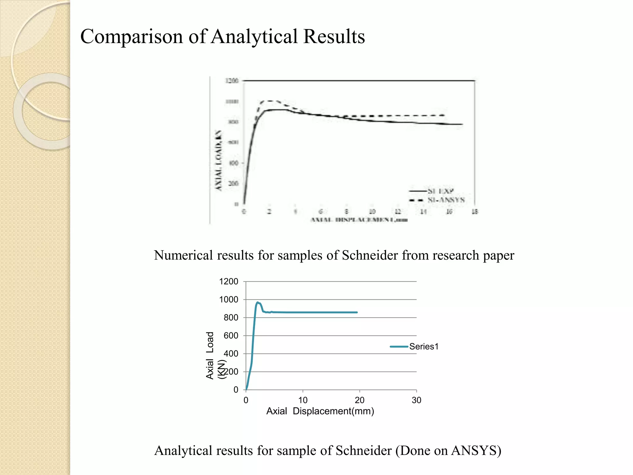
4. Manual Calculations
Following are the formulae used in calculating the ultimate axial load
capacity of CFST columns (these formulae are based on AISC-LRFD):
1. c2 =Fmy/FE = (KL/rmπ)2 * (Fmy/Em)
2. Em = Es + 0.40Ec (Ac/As)
3. Fmy = Fy + 0.85fc (Ac/As)
4. Fcr = (.658 𝑐
2
) Fmy {for c ≤1.5}
5. Fcr = (.877/ 𝑐
2) Fmy {for c>1.5}
6. Pcr = As Fcr
7. Pc = Pcr/ (1 + (AsEs/AcEc))
8. Ps = Pcr/ (1 + (AcEc/AsEs))
Axially Loaded Concrete Filled Steel Tubes By Schneider
5. 2 :- Column Slenderness Parameter
FE :- Euler Buckling Stress for Column
rm :- radius of gyration of the steel tube
KL :- effective simply supported column length
Em :- modified elastic modulus
Fmy :- modified yield strength
Es :- modulus of elasticity of steel
As :- Area of steel
Fy :- yield strength of steel
Ec :- modulus of elasticity of concrete
Ac :- area of concrete
fc :- strength of concrete
Pcr :- load on composite section
Pc :- load on concrete
Ps :- load on steel
6. Step by step procedure to calculate strength of CFST column:-
Given-
Ac = 14645 mm2
As = 1535 mm2
Ec = 26611 N/mm2
Es = 180518 N/mm2
fc = 30.454 N/mm2
Fy = 356 N/mm2
L = 611.04 mm
Step 1: Calculation of Column slenderness ratio
2 =Fmy/FE = (KL/rmπ)2 * (Fmy/Em)
Fmy = Fy + 0.85ƒc (Ac/As)
Fmy = 356 +.85*(30.454)*(14645/1535)
Fmy= 602.97 N/mm2
Em = Es + 0.40Ec (Ac/As)
Em = 180518 + .4*(26611)*(14645/1535)
Em = 2.82 x 10⁵ N/mm2
K = .65 (from Indian Code)
7. rm =
(𝐵𝐷3−𝑏𝑑3
12(𝐵𝐷−𝑏𝑑)
B = 127.3 mm D = 127.3 mm
b = 121 mm d = 121 mm
rm = 51.9 mm
c
2 =
.65∗611.04
51.9∗𝜋
2
x
603
2.82∗105
c
2 = 0.0126
c = 0.112
Step 2 : Calculation of Load bear by column
Pcr = As Fcr
As- c < 1.5 :formula use
Fcr = (.658 𝑐
2
) Fmy
Fcr = (.658.0126) * 603
Fcr = 599.8 N/mm2
Pcr = 1535 x 599.8
Pcr = 920693 N
8. Step 3 : Calculation of Strength of steel and concrete due to combine
effect.
Load bear by concrete alone given by :
Pc = Pcr/ (1 + (ASES/ACEC))
Pc =
920693
1+
180518∗1535
14645∗26611
= 538097.8 N
Strength of Concrete =
𝑃𝑐
𝐴 𝑐
=
538097.8
14646
= 36.74 N/mm2
Load bear by steel tube alone:
PS = Pcr / (1 + (ACEC/ASES))
PS =
920693
1+
14645∗26611
180518∗1535
= 382595.211 N
Strength of steel =
𝑃𝑠
𝐴 𝑠
=
382595.211
1535
= 249 .24N/mm2
10. Behavior of Centrally Loaded Concrete-Filled Steel Tube Short
Columns By Sakino, Morino and Nishiyama
Following are the formulae used in calculating the ultimate axial load capacity of
CFST columns
1. 1/S = 0.698 + 0.128 (B/t)2 (σsy/Es)( 4.00/6.97 )
2. σ scr = Min (σsy, Sσsy)
3. Nu = Nsu + Nc0
4. Nsu = As σ scr
5. Nc0 = AcYuf`c
6. YU = 1.67Dc
-.112
B = Width of square steel t ube
σsy = Tensile Yield Stress of Steel Tube
f'c = Cylinder strength of concrete
√αs = Normalized width-to-thickness ratio of square of steel tube(B/t) √
σsy//Es.
ϒu = Strength Reduction for concrete
11. Given :
Section(148X148) mm
t = 4.38 mm
σsy = 262 N/mm2
f`c = 40.5 N/mm2
As = 2516.2224 mm2
B = width of square steel tube
t = wall thickness of steel tube
Dc = diameter of concrete core (mm)
Ac = area of concrete at cross section
As = area of steel tube at cross section
S = axial load capacity factor of steel tube
Nsu = axial load capacity of square steel tube short columns
Nexp = experimental axial load capacity of concrete-filled steel tube
short columns
Nc0 = nominal squash load
σsy = Tensile Yield Stress of Steel Tube
f ‘c = Cylinder strength of concrete
Yu = strength reduction factor for concrete
12. Ac = 19387.77 mm2
Dc = 323 mm
Step 1 : Calculation of Axial Load Capacity Factor (S)
1/S = 0.698 + 0.128 (B/t)2 σsy/Es 4.00/6.97
= 0.698 + 0.128(148/4.38)2 (262/2*105)( 4/6.97)
= 0.8078
S = 1.237
Step 2 : Calculation of ultimate compressive stress
σ scr = Min (σsy, Sσsy)
σsy = 262 N/mm2
Sσsy = 1.23*262
Sσsy = 325.3N/mm2
σ scr = 262N/mm2
As = 1482 – 139.242
AS = 2516.2224 mm2
Ac = 19387.77 mm2
Step 3 Calculation of Axial Load Capacity
Nu = Nsu + Nc0
Nsu = As σ scr
13. = 2516.2224*262
= 659250.26 N
Yu = 1.67Dc
-.112
= 1.67*323-.112
= 0.8743
Nc0 = AcYuf`c
= 19387.77*0.8743*40.5
= 686504.456 N
Nu = Nsu + Nc0
= 659250.26 + 686504.456
= 1345754.7 N
Nu = 1345.7KN
Nex = 1414 KN
Nex/Nu = 1414/1345.7
= 1.05
14. Specimen B
(mm)
Tube
thicknes
s
(mm)
σsy f ‘c
(N/mm
2 )
B/t √αs
ϒU N Exp
(KN)
N Exp / Nu
CR4- A-4-1 Experiment
al Data
148 4.38 262 40.5 33.8 1.21 0.95 1414 1.02
Calculated
Data
148 4.38 262 40.5 33.8 1.21 0.87 1345 1.05
CR4- C-4-1 Experiment
al Data
215 4.38 262 41.1 49.1 1.75 0.91 1777 0.92
Calculated
Data
215 4.38 262 41.1 49.1 1.75 0.87 1980 0.89
TABLE 2
15. STEP BY STEP PROCEDURE FOR ANALYSIS
Import model from solidworks in (.igs) format to ANSYS (Mechanical APDL)
17. Select Preprocessor > Element Type > Add > SOLID45 >apply
>SOLID65> apply > CONTA173 > close.
18. Select Material Prop> Material Model > Structural > Linear >Elastic>
isotropic > EX= 2e5>PRXY =.3>Add new material id > EX=
3e7>PRXY =.3>>close.
19. As model is already imported no need to go for modelling part
Mesh > Mesh tool > Set Solid45 >material id 1>Mesh size 10>
Sweep>Select outer surface i.e steel surface and end plate and bottom plate
> apply > Mesh tool> set solid 65> material id 2>mesh size 10> Mesh>
select inner core i.e concrete core>apply.
21. Modelling> Contact Pair > add new contact> Pick the surface > next>
again pick surface > create symmetric pair > coefficient of friction 0.3>
create.
22.
23. Loads > Define load >Apply >structural>Displacement> on area > Select
bottom surface >apply> All DOF > value of Load is 0>select upper plate
Area >apply> UX and UY is 0.
24. Solution > Analysis type> Sol'n control >automatic stepping on >min no
of substep 1> max. no. of substep 40>
25. Comparison Of Manual Results With Experimental Results (Research
Paper by Schneider)
RESULT
Shape rm KL/rm Fmy
(MPa)
Em
(MPa)
c Pcr
(Kn)
S1 Experimental
Data
50.7 12.0 603.1 282,246 .177 914
S1 Calculated
Data
51.9 7.65 602.9 282,073 .112 920
S2 Experimental
Data
50.0 12.2 505.4 259,862 .171 1037
S2 Calculated
Data
51.8 7.64 505.5 256,206 .108 1044
26. Comparison of Analytical Results
Numerical results for samples of Schneider from research paper
0
200
400
600
800
1000
1200
0 10 20 30
Series1
Axial Displacement(mm)
AxialLoad
(KN)
Analytical results for sample of Schneider (Done on ANSYS)
27. Conclusion
Results Ultimate Axial Load
Capacity (kN)
Percentage Error %
Experimental Result 914
Manual Result 920 0.652%
Analytical Result 967.3 4.8%
28. References
SCHNEIDER S P, Axially Loaded Concrete-Filled Steel Tubes. Journal of Structural
Engineering, ASCE, 1998, Vol. 124, No. 10, pp.1125-1138.
HAN L H, Tests on stub columns of concrete-filled RHS sections, Journal of
Constructional Steel Research, 2002, Vol. 58, pp. 353-372.
SAKINO K, NAKAHARA H, MORINO S AND NISHIYAMA I, Behavior of
Centrally Loaded Concrete-Filled Steel-Tube Short Columns, Journal of Structural
Engineering, ASCE, 2004, Vol. 130, No. 2, pp. 180-188.
GUPTA P K, KHAUDHAIR ZIYAD A, AHUJAA K, A study on load carrying
capacity and behavior of concrete filled steel tubular members subjected to axial
compression. In: the 11th International Conference on Concrete Engineering and
Technology 2012, 2012, Putrajaya, Malaysia, p. 337-342. 14 ANSYS Inc, User
Guides, Release 12.
HUANG C S, YEH Y K, LIU G Y, HU H T, TSAI K C, WENG Y T, WANG S H
AND WU M H, Axial Load Behavior of Stiffened Concrete-Filled Steel Columns.
Journal of Structural Engineering, ASCE, 2002, Vol. 128, No. 9, pp. 1222-1230.
ELLOBODY E, YOUNG B AND LAM D, Behavior of normal and high strength
concrete-filled compact steel tube circular stub columns,. Journal of Constructional
Steel Research, 2006, Vol. 62, pp. 706-715. 18 MANDER J B, PRIESTLEY M J N
AND PARK R, Theoretical Stress-Strain model of confined concrete. Journal of
Structural Engineering, 1988, Vol. 114, No. 8, pp. 18041826