Principals avantatges: TecnologiaEstàndard i Normalitzada El sistema KNX és un sistema Estàndar i Normalitzat : Estàndard: Més de 100 fabricants europeus. Tecnologia independent del fabricant Interoperabilitat de productes. Normalizat: Europa: UNE-EN 50090 Mundial: ISO/IEC 14543
3.
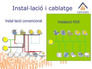
Planificació més simple.Canvis i expansió sense problemes. Conexió de dispositius individualment. Sistemes bus
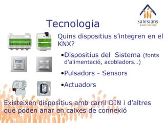
Tecnologia Quins dispositiuss’integren en el KNX? Dispositius del Sistema (fonts d’alimentació, acobladors…) Pulsadors - Sensors Actuadors Existeixen dispositius amb carril DIN i d’altres que poden anar en caixes de connexió
6.
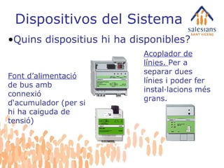
Dispositivos del SistemaQuins dispositius hi ha disponibles? Font d’alimentació de bus amb connexió d‘acumulador (per si hi ha caiguda de tensió) Acoplador de línies. Per a separar dues línies i poder fer instal·lacions més grans.
7.
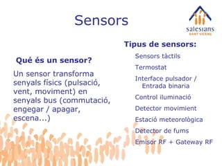
Sensors Tipus desensors: Sensors tàctils Termostat Interface pulsador / Entrada binaria Control iluminació Detector movimient Estació meteorològica Detector de fums Emisor RF + Gateway RF Qué és un sensor? Un sensor transforma senyals físics (pulsació, vent, moviment) en senyals bus (commutació, engegar / apagar, escena...)
8.
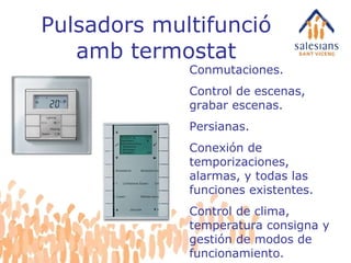
Pulsadors multifunció ambtermostat Conmutaciones. Control de escenas, grabar escenas. Persianas. Conexión de temporizaciones, alarmas, y todas las funciones existentes. Control de clima, temperatura consigna y gestión de modos de funcionamiento.
9.
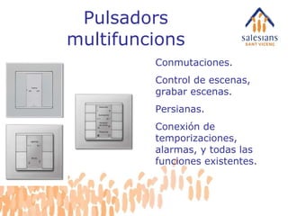
Pulsadors multifuncions Conmutaciones.Control de escenas, grabar escenas. Persianas. Conexión de temporizaciones, alarmas, y todas las funciones existentes.
10.
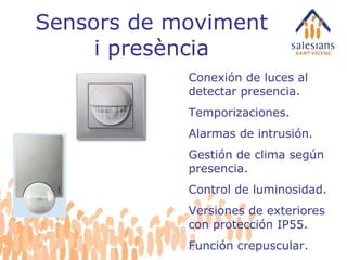
Sensors de movimenti presència Conexión de luces al detectar presencia. Temporizaciones. Alarmas de intrusión. Gestión de clima según presencia. Control de luminosidad. Versiones de exteriores con protección IP55. Función crepuscular.
11.
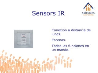
Sensors IR Conexióna distancia de luces. Escenas. Todas las funciones en un mando.
12.
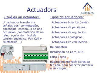
Actuadors Tipos deactuadores: Actuadores binarios (relés). Actuadores de persianas. Actuadores de regulación. Actuadores analógicos. Actuadores de calefacción. De empotrar Instalación en Carril DIN Falso Techo Habitualmente relés libres de tensión, para conectar potencia a las cargas. ¿Qué es un actuador? Un actuador transforma señales bus (conmutación, encendido, escena...) en una actuación (conmutación de un relé, regulación, nivel de tensión analógico, Fan Coil y calefacción...)
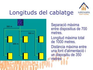
Longituds del cablatge350 m 350 m 300 m Separació màxima entre dispositius de 700 metres. Longitud màxima total de 1000 metres. Distància màxima entre una font d'alimentació i un dispositiu de 350 metres
19.
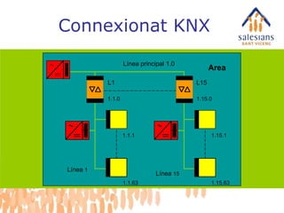
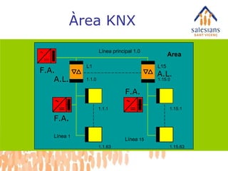
Àrea KNX AreaF.A. F.A. F.A. A.L. A.L. Línea principal 1.0 Línea 1 Línea 15 L1 L15 1.15.1 1.15.63 1.1.1 1.1.63 1.1.0 1.15.0
20.
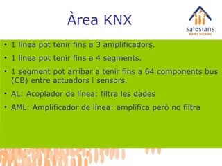
Àrea KNX 1línea pot tenir fins a 3 amplificadors. 1 línea pot tenir fins a 4 segments. 1 segment pot arribar a tenir fins a 64 components bus (CB) entre actuadors i sensors. AL: Acoplador de línea: filtra les dades AML: Amplificador de línea: amplifica però no filtra
21.
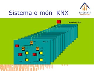
Sistema o món KNX 3 4 5 6 7 8 9 10 11 12 13 14 15 Area línea 0.0 Línea principal 1.0 Línea 1 Líniea 15 LK1 LK15 1.15.1 1.15.63 2 1.1.1 1.1.63 1.1.0 1.15.0 Area 1 BK1 1.0.0
22.
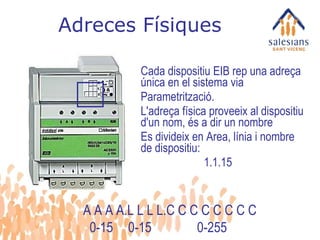
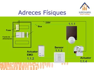
Adreces Físiques Cadadispositiu EIB rep una adreça única en el sistema via Parametrització. L'adreça física proveeix al dispositiu d'un nom, és a dir un nombre Es divideix en Area, línia i nombre de dispositiu: 1.1.15 A A A A.L L L L.C C C C C C C C 0-15 0-15 0-255
23.
Adreces Físiques ActuatorSensor Actuator EMO Fuse Fuente de alimentacion 1.1.3 Bus 230V 1.1.1 1.1.2 1.1.4
24.
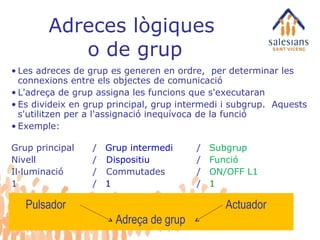
Adreces lògiques o de grup Les adreces de grup es generen en ordre, per determinar les connexions entre els objectes de comunicació L'adreça de grup assigna les funcions que s'executaran Es divideix en grup principal, grup intermedi i subgrup. Aquests s'utilitzen per a l'assignació inequívoca de la funció Exemple: Grup principal / Grup intermedi / Subgrup Nivell / Dispositiu / Funció Il·luminació / Commutades / ON/OFF L1 1 / 1 / 1 Pulsador Actuador Adreça de grup
25.
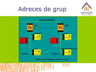
Adreces de grupBereich Línea principal Línea 1 LK1 LK2 Pulsador 1 Luz 1 1/1/2 A 1/1/1 1/1/1 S 1.1.1 1.1.2 1.2.1 A 1/1/2 1.2.2 S 1/1/2 Detector movimiento Luz 2 Line 2 Direcciones de grupo en tres niveles
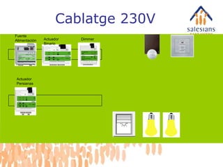
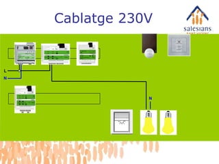
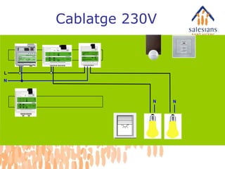
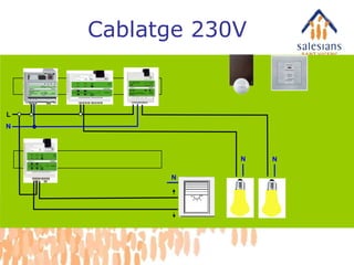
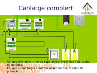
L N NN N Cablatge complert Cal que existeixin 4mm de separació entre el bus i els cables de potència. Cal que el bus tingui el mateix aïllament que el cable de potència.
#4 Ventajas: Flexible, simple planning: you determine the functions and decide where the switches should be installed. You can even decide later whether switch x should really switch lamp y or whether another switch should fulfil this function. This also means: Flexibility for changes and expansion at any time - even after installation has been completed. Perhaps the switch at the lounge door should no longer control only one lamp, but rather dim all the lamps in the room? Changes present no problem and can be carried out without caulking and thus without the dirt this involves. And expansions are a lot less complicated than with conventional installations. Perhaps you want to use the switch not only to control the lighting, but also the music system, to create a cosy atmosphere at the touch of a button. No problem, as INSTABUS links the individual subsections of an electrical installation, such as the light and blind control. Complex demands can be fulfilled with considerably less effort and at less expense than with a conventional installation. Central display and operation of all technological functions in the house. Of course, you can also control Instabus from your PC in your study or display statuses - at the click of a mouse or with a touch-screen monitor. Instabus minimises operational and energy costs. The energy consumption through heating and lighting is controlled automatically and is constantly adapted to suit the current living situation. Example: window open - heating off, unnecessarily activated power-consuming devices are switched off, etc.
#5 Ventajas: Flexible, simple planning: you determine the functions and decide where the switches should be installed. You can even decide later whether switch x should really switch lamp y or whether another switch should fulfil this function. This also means: Flexibility for changes and expansion at any time - even after installation has been completed. Perhaps the switch at the lounge door should no longer control only one lamp, but rather dim all the lamps in the room? Changes present no problem and can be carried out without caulking and thus without the dirt this involves. And expansions are a lot less complicated than with conventional installations. Perhaps you want to use the switch not only to control the lighting, but also the music system, to create a cosy atmosphere at the touch of a button. No problem, as INSTABUS links the individual subsections of an electrical installation, such as the light and blind control. Complex demands can be fulfilled with considerably less effort and at less expense than with a conventional installation. Central display and operation of all technological functions in the house. Of course, you can also control Instabus from your PC in your study or display statuses - at the click of a mouse or with a touch-screen monitor. Instabus minimises operational and energy costs. The energy consumption through heating and lighting is controlled automatically and is constantly adapted to suit the current living situation. Example: window open - heating off, unnecessarily activated power-consuming devices are switched off, etc.
#6 Technology Of which devices does the INSTABUS EIB system consist? The basics Products System devices Sensors Actuators ETS
#7 System devices Which devices are available? Power supply Coupling unit
#9 Sensors in the UP range Single, 2, 3 and 4-gang pushbutton insert Single and 2-gang bus coupling unit insert IR receiver Room temperature control ARGUS movement detector
#10 Sensors in the UP range Single, 2, 3 and 4-gang pushbutton insert Single and 2-gang bus coupling unit insert IR receiver Room temperature control ARGUS movement detector
#11 Sensors in the UP range Single, 2, 3 and 4-gang pushbutton insert Single and 2-gang bus coupling unit insert IR receiver Room temperature control ARGUS movement detector
#12 Sensors in the UP range Single, 2, 3 and 4-gang pushbutton insert Single and 2-gang bus coupling unit insert IR receiver Room temperature control ARGUS movement detector
#13 Actuators Flush-mounted UP Series installation REG-K Installation EB
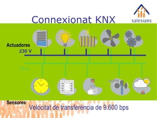
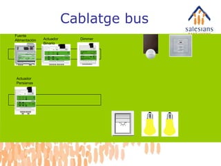
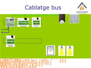
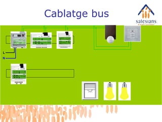
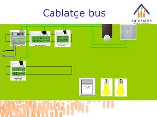
#14 Here is an example of an installation on INSTABUS basis. The simple structure of the system is clearly obvious. All devices are connected to each other via a separate cable, the so-called bus line. The system components communicate via the line. And it makes no difference whether switch x should now switch the light in the lounge or whether you decide years later that the same switch should also switch the lighting in the hallway. INSTABUS from Merten adapts flexibly to suit your wishes and requirements.
#15 Sensors and actuators A short introduction to the technology of INSTABUS EIB demonstrates how all this is possible. The system is divided into sensors and actuators, which are all connected to the bus line. Sensors are devices such as pushbuttons, movement detectors, wind sensors, clocks, brightness sensors or remote controls, which can process an order and pass it on in the form of data. They are the devices which give the orders, so to speak. Actuators are devices such as switching, blind and dimming actuators or also displays, which transform the data from the sensors into actions. They are the devices which carry out orders. They can, however, also send messages to the bus, e.g. communicate their status, which then appears on a display. The programming determines which actions are executed when, how and by which devices. The programming takes place with software (called ETS), in which all logical connections and parameters are set. Now it becomes clear why Instabus is so flexible and convenient for the user. The connections take place via the bus line, to which all system users are connected. The functions are not assembled rigidly, but rather logically, and can also be changed again in a logical manner.
#16 Lines are connected via coupling units and this is then referred to as the EIB area. Up to 15 secondary lines can be connected to an EIB area via a line coupling unit and a main line. The coupling units metallically separate the lines and filter the telegrams so that the only telegrams transmitted into other lines are ones which have to be received there. This keeps the load to a minimum. The correct handling of coupling units is therefore very important. The EIB Tool Software creates the filter tables on the basis on the parameterisation; these are then loaded into the coupling unit.
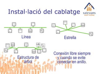
#17 Cable installation BUS Possibilities: Line Star or Tree structure Bus lines may be branched as required and require no terminating resistors.
#18 Cable installation BUS Possibilities: Line Star or Tree structure Bus lines may be branched as required and require no terminating resistors.
#19 Permitted cable lengths: One line contains the following distance data: Maximum length: 1000 m Max. distance between 2 devices: 700 m Max. distance between power supply and first device: 350 m
#20 Lines are connected via coupling units and this is then referred to as the EIB area. Up to 15 secondary lines can be connected to an EIB area via a line coupling unit and a main line. The coupling units metallically separate the lines and filter the telegrams so that the only telegrams transmitted into other lines are ones which have to be received there. This keeps the load to a minimum. The correct handling of coupling units is therefore very important. The EIB Tool Software creates the filter tables on the basis on the parameterisation; these are then loaded into the coupling unit.
#21 Lines are connected via coupling units and this is then referred to as the EIB area. Up to 15 secondary lines can be connected to an EIB area via a line coupling unit and a main line. The coupling units metallically separate the lines and filter the telegrams so that the only telegrams transmitted into other lines are ones which have to be received there. This keeps the load to a minimum. The correct handling of coupling units is therefore very important. The EIB Tool Software creates the filter tables on the basis on the parameterisation; these are then loaded into the coupling unit.
#22 EIB overall system: The coupling units are used as backbone coupling units between the main line and the backbone line. The same coupling units are used as repeaters for 64 users each. Overall topology of EIB Up to 15 ranges can be connected to an EIB overall system via a backbone line. The transfer speed of the backbone is also 9,600 bit/s. This means there can be more than 14,000 users in an EIB system. In the case of systems with a very high backbone load (e.g. with visualisations or communication with management levels), it is possible to couple the main lines via gateways on the Ethernet, in order to be able to transport more data. In this way, systems with far more than 14,000 users can be created.
#23 Physical address Each EIB device receives a unique address in the system via parameterisation The physical address provides the device with a name, i.e. a number It is divided into area, line and device number Example: Area Line Device 1.1.15 This physical address is loaded once via the bus from the PC into the bus coupling unit, whereby a small programming button must be pressed on the corresponding device. Physical address: Divided into area, line and device number. The physical address is noted at the points in order to understand which address has been allocated to the device.
#25 3-digit group address Group addresses are generated in order to determine the connections between the communications objects The group address allocates the functions to be executed It is divided into a main group, a middle group and a subgroup. These are used for the unambiguous allocation of the function. Example: Main group Middle group Subgroup Level Device Function 1st floor Lighting Lamp group 1 1/1/1 It is the task of the EIB System integrator to determine an optimal structure of the group addresses for the project in hand. Actuators can respond to several group addresses, but sensors can only transmit one group address.
#38 EIB operation The bus is connected to the PC with an RS-232 interface for operation. Now, the physical address and the application with the connections and parameters can be chosen and loaded into the EIB devices. This procedure takes approximately 20 seconds. The programming button on the device has to be pressed once to allocate the physical address. The remaining data can be changed at any time, e.g. if you wish to make changes at a later point from anywhere in the bus system.