Download to read offline

![International Research Journal of Engineering and Technology (IRJET) e-ISSN: 2395-0056
Volume: 04 Issue: 09 | Sep -2017 www.irjet.net p-ISSN: 2395-0072
© 2017, IRJET | Impact Factor value: 5.181 | ISO 9001:2008 Certified Journal | Page 1050
iv. Roof Spoiler
Roof spoiler is an aerodynamic device that is usually
attached to the rear of car’s roof. It is custom designed to fit
the upper window section and installs directly above the
glass.
v. Lip Spoiler
Lip spoiler is a best choice for the driver who prefers a more
subtle and at the same time appealing upgrade. Installed on
the lip of the trunk, this styling accessory delivers a sporty
image that is easy to be recognized. The lip spoiler can peer
off the rear of the automobile without being too tall or wide.
It also underlines a sleek lines of the car.
vi. Truck spoiler
When attached to any truck’s rear, these accessories make it
appear aggressive like a roadster. Different types of truck
spoilers are suitable for different types of truck brands and
their models.
3. LITERATURE SURVEY
Mustafa Cakir [1] , in this paper,“CFD Study on Aerodynamic
Effects of a Rear wing/spoiler on a passenger vehicle”, The
aerodynamic lift, drag and flow characteristics of a high-
speed (~65 mph) generic sedan passenger vehicle with a
spoiler and without a spoiler situations were numerically
investigated. The numerical analyzeofhigh-speedpassenger
car with first rear spoiler design (case #2, which was a wing
style spoiler) has showed that the aerodynamic drag is
reduced from 0.232 to 0.192, which is 17% drag reduction,
and it also increases negative lift by reducing the lift
coefficient from -0.222 to -0.239, which is 7% lift reduction.
McKay, Noah J[7], Aerodynamics plays a very importantrole
in motorsports. Car manufacturers around the world have
been fascinated and influenced by the various aerodynamic
improvements that are used in racing. There has been a
constant effort on their side to incorporate these changes to
road vehicles not just as an aesthetic design feature but also
since they believe that these features can contribute to
improving fuel economy and vehicle handling. One of the
main areas of concern in racing is to balance aerodynamic
forces and to streamline the air flow across the body
towards improving stability and handling characteristics,
especially, while cornering. At present, formula racing cars
are regulated by stringent FIA norms, there is a constraint
for the dimensions of the vehicle used, engine capacity,
power output and emission. It is difficult to obtain the
optimum aerodynamic performance withtheexisting racing
car. There is a need for improvement in the aerodynamic
performance of these race cars by using add-on devices
locally with different configurations to streamline and
channelize the airflow besides reducing aerodynamicforces
and providingstabilitythatimprovescorneringandhandling
characteristics.
Aniruddha Patiletal[9] The development of low form factor
flight controls is driven by the benefits of reducing the
installed volume of the control deviceand/orminimizing the
change in external geometry, with particular application to
flight control of low observable aircraft. For this work, the
term „low form factor‟ does not refer to the aspect ratio of
the control device rather the overall installed volume. This
thesis compares the use of low form factor geometric and
fluid devices on a NACA 0015 aerofoil section through two-
dimensional numerical analysis and low speed wind tunnel
experiments. The geometric spoiler is implemented as a
small (boundary layer scale) variable height tab oriented
normal to the local surface, referred to as a Micro Geometric
Spoiler (MiGS). The fluidic spoiler is implemented as an air
jet tangential to the local surface acting in the forward
direction, referred to as a Counter-Flow Fluidic Spoiler
(CFFS). Two chord wise spoiler locations were considered:
0.35c and 0.65c. Numerical analysis was undertaken using a
commercial CFD code using an unsteadysolverandk-omega
shear-stress-transport turbulence model. Experimental
forces and moments were measured via an overhead force
balance, integrated surface pressures and pressure wake
survey. Device performance is assessed against the
magnitude of control achievable compared to macro scale
spoilers and trailing edge controls (effectiveness), the ratio
of aerodynamic output to control input (efficiency or gain),
the shape of control response curve (linearity), and the
degree of control cross coupling.
4. MODELLING
4.1 PTC Creo Parametric
The flagship application in the PTC Creo Suite, PTC Creo
Parametric is the only software you need for 3D CAD. With
PTC Creo Parametric, you can seamlessly combine
parametric and direct modeling; open non-native CAD data
and collaborate with almost anyone thanks to Unite
technology; and relax knowing all downstream deliverables
will update automatically. Combine this rangeofcapabilities
with ease-of use, and you have a product design accelerator.
Figure 1: 3D elements/ Direct Modeling](https://image.slidesharecdn.com/irjet-v4i9185-171005092156/85/CFD-Analysis-on-Aerodynamic-Effects-on-a-Passenger-Car-2-320.jpg)
![International Research Journal of Engineering and Technology (IRJET) e-ISSN: 2395-0056
Volume: 04 Issue: 09 | Sep -2017 www.irjet.net p-ISSN: 2395-0072
© 2017, IRJET | Impact Factor value: 5.181 | ISO 9001:2008 Certified Journal | Page 1053
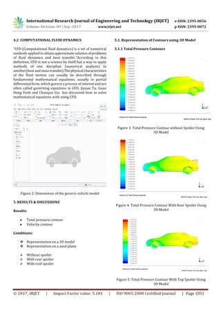
5.2.2. Velocity Contours
Figure 12: Total Velocity Contour without Spoiler using
Axial Plane
Figure 13: Total Velocity Contour With Rear Spoiler Using
Axial Plane
Figure 14: Total Velocity Contour With Top Spoiler Using
Axial Plane
6. CONCLUSION
The aerodynamic lift, drag and flow characteristicsofa high-
speed (~100 Kmph) generic sedan passenger vehicle with a
spoiler and without a spoiler situations were numerically
investigated.Numerical analysis has showed us that the
spoiler design, which was mounted to the rear-endprovided
more negative lift force than the roof spoiler did but
provided less drag reduction.Roof spoiler provided drag
reduction but the negative lift force has been increased. It is
known that having down force (i.e. negativeliftforce).Sedan
car with roof Increases tires capability to produce cornering
force, Stabilizes vehicle sat high speed, Improves braking
performance, Gives better traction, Reduceinliftmayleadto
reduce of dirt on the rear surface, Reduce in drag leads to
maximum speed for a given engine power, compared torear
spoiler sedan car.
REFERENCES
[1] Mustafa Cakir , “CFD Study on Aerodynamic Effects of a
Rear wing/spoiler on a passenger vehicle”.Submitted in
partial fulfillment of the requirements for the degree of
masterof science in mechanical engineering in the school of
engineering at Santa Clara university, California.
[7] McKay, Noah J, 2002. “The Effect of Wing Aerodynamics
on Race Vehicle
Performance”. SAE Publications.
[9] Aniruddha Patil et al, “Study of Front Wing of Formula
One car using computational fluid dynamics”.
[10] Abdulnaser Sayma, “Computational Fluid
Dynamics”.computational analysis of base drag reduction
using active flow control
[11] G. Fillola et al, “Experiental Study and Numerical
Simulation of Flow Around Wing Control Surface”.
[12] P.M. VAN LEEUWEN “computational analysis of base
drag reduction using active flow control” aerospace
engineering at delft university of technology, november
2009.
[13] Dileep P. Menon, samir kamat
G.,yagnavalkyas.mukkamala,prakashS.kulkarni“toimprove
the aerodynamic performance of a model hacth back car
with the addition of rear roof spoiler” CFD sympo
2014,banglore. 16th Annual CFD symposium, august 11-
12,2014.
[14] MOHAMMAD MASHUD , MAUSUMI FERDOUS AND
SHAHRIAR HOSSAIN OMEE, Department of mechanical
engineering, kahulna university of engineering and
technology, KUET,Khulna -9203,bangladesh“Effectofspoiler
position on aerodynamic characteristics of an airfoil”](https://image.slidesharecdn.com/irjet-v4i9185-171005092156/85/CFD-Analysis-on-Aerodynamic-Effects-on-a-Passenger-Car-5-320.jpg)
![International Research Journal of Engineering and Technology (IRJET) e-ISSN: 2395-0056
Volume: 04 Issue: 09 | Sep -2017 www.irjet.net p-ISSN: 2395-0072
© 2017, IRJET | Impact Factor value: 5.181 | ISO 9001:2008 Certified Journal | Page 1054
International Journal of mechanical and mechatronics
engineering IJMMEIJENS vol:12 No:06 1.
[15] WOLF-HEINRICH HUCHO, GINO WOVSRAN
“AERODYNAMICS OF ROAD VEHICLES” Annu. Rev. Fluid
Mech. 1993.25:485-537,1993.
[16] Jiang, F., “Assessing Computational Fluid Dynamics
Predictions for Control Surface Effectivness ”, Journal of
Aircraft, vol. 38, n°6, 2001
[17] Archambeau , J.P., Dor , J.B., Michonneau , J.F., Brail J.F.,«
etude des effects latéraux autour d’un profil bidimensionnel
dans la soufflerie T2. Mesure par vélocimétrie laser et
utilisation de différents contrôles actifs », PV OA n°15/2891
AN 169D (DERAT n°15/5015.24), octobre 1991
[18] . Kieffera W, Moujaesb S and Armbyab N (2006), “CFD
Study of SectionCharacteristics of Formula Mazda Race Car
Wings”, Mathematical andComputer Modelling, Vol. 43,Nos.
11 -12, pp. 1275-1287.
[19] Mohd Syazrul Shafiq B Saad (2010), “Study of F1 Car
Aerodynamics FrontWing Using Computational Fluid
Dynamics (Cfd)”, Universiti MalaysiaPahang, December.
[20] Mack, M.D, Seetharam, H. C., Kuhn, W. G., Bright, J. T.,
“Aerodynamics of spoiler control devices,” presented at the
AIAA Aircraft Systems and Technology meeting, New York,
1979.
[21] Flower, J.W., “Lift and rolling moment duetospoilers on
wings with flaps undeflected at subsonic speeds,” ESDU,
90030b, pp. 1-30, 1999.](https://image.slidesharecdn.com/irjet-v4i9185-171005092156/85/CFD-Analysis-on-Aerodynamic-Effects-on-a-Passenger-Car-6-320.jpg)

This document discusses computational fluid dynamics (CFD) analysis of aerodynamic effects on a passenger car with and without spoilers. It first provides background on spoilers and their purpose in improving vehicle stability at high speeds. It then details the CFD modeling process using CAD software to model a baseline car model and variations with rear and roof spoilers. CFD analysis was performed to determine total pressure and velocity contours and estimate drag and lift forces. Results showed that a roof spoiler provided the most drag reduction and increased negative lift, improving stability at high speeds, while a rear spoiler primarily increased negative lift with less drag reduction.


