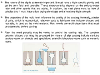
CERAMIC MATERIALS
Introduction
 Ceramic materials are inorganic and nonmetallic materials.
 Most ceramics are compounds between metallic and nonmetallic elements
for which the interatomic bonds are either totally ionic or predominantly ionic
but have some covalent character.
Ceramic Structures
 Ceramics are composed of at least two elements and often more, their
crystal structures are generally more complex than those for metals. The
atomic bonding in these materials ranges from purely ionic to totally
covalent.
Crystal Structures
 For those ceramic materials for which the atomic bonding is predominantly
ionic, the crystal structures may be thought of as being composed of
electrically charged ions instead of atoms.
 The metallic ions or cations are positively charged, because they have given
up their valence electrons to the nonmetallic ions or anions, which are
negatively charged.
 Two characteristics of the component ions in crystalline ceramic materials
influence the crystal structure, 1. the magnitude of the electrical charge on
each of the component ions and 2. the relative sizes of the cations and
anions.
 With regard to the first characteristic, the crystal must be electrically neutral,
ie. all the cation positive charges must be balanced by an equal number of
anion negative charges. The chemical formula of a compound indicates the
ratio of cations to anions or the composition that achieves this charge
balance. For example, in calcium fluoride, each calcium ion has a +2 charge
(Ca+2
) and associated with each fluorine ion is a single negative charge (F-
).
Thus, there must be twice as many F-
as Ca+2
ions, which is reflected in the
chemical formula CaF2.
 The second criterion involves the sizes or ionic radii of the cations and
anions, rC and rA respectively. Because the metallic elements give up
electrons when ionized, cations are ordinarily smaller than anions, and,
consequently, the rC/rA ratio is < 1. Each cation prefers to have as many
nearest-neighbor anions as possible. The anions also desire a maximum
number of cation nearest neighbors.
 Stable ceramic crystal structures form when those anions surrounding a
cation are all in contact with that cation. The coordination number is
related to the cation–anion radius ratio.
 For a specific coordination number, there is a critical or minimum ratio for
which this cation–anion contact is established. This ratio may be determined
from pure geometrical considerations.
AX-Type Crystal Structures
 Some of the common ceramic materials are those in which there are equal
numbers of cations and anions. These are often referred to as AX
compounds, where A denotes the cation and X the anion.
 The most common AX crystal structure is the sodium chloride (NaCl) type.
The coordination number for both cations and anions is 6 and therefore the
cation–anion radius ratio is between approximately 0.414 and 0.732.
 Similarly, CsCl, ZnS structures.
AmXp-Type Crystal Structures
 If the charges on the cations and anions are not the same, a compound can
exist with the chemical formula AmXp.
 An example is CaF2. The ionic radii ratio rC/rA for CaF2 is about 0.8 and
coordination number is 8. Calcium ions are positioned at the centers of
cubes, with fluorine ions at the corners.
 The chemical formula shows that there are only half as many Ca+2
ions as F-
1
ions and therefore the crystal structure would be similar to CsCl, except
that only half the center cube positions are occupied by ions.
AmBnXp-Type Crystal Structures
 It is also possible for ceramic compounds to have more than one type of
cation. For two types of cations (represented by A and B), their chemical
formula may be designated as AmBnXp.
 For example, BaTiO3. Ba+2
ions are situated at all eight corners of the cube
and a single Ti+4
is at the cube center, with ions located at the center of each
of the six faces.
Ceramic Density Computations
 It is possible to compute the theoretical density of a crystalline ceramic
material from unit cell data with the following formula
 Where, is number of formula units within the unit cell
is the sum of the atomic weights of all cations
is the sum of the atomic weights of all anions
VC is the unit cell volume
NA is the Avogadro’s number, 6.023x10²³
Imperfections in ceramics
Atomic point defects
 Atomic defects involving host atoms may exist in ceramic compounds. As
with metals, both vacancies and interstitials are possible; however, because
ceramic materials contain ions of at least two kinds, defects for each ion
type may occur. For example, in NaCl, Na interstitials and vacancies and Cl
interstitials and vacancies may exist.
 The expression defect structure is often used to designate the types and
concentrations of atomic defects in ceramics. Because the atoms exist as
charged ions, when defect structures are considered, conditions of
electroneutrality must be maintained. Electroneutrality is the state that exists
when there are equal numbers of positive and negative charges from the
ions. As a consequence, defects in ceramics do not occur alone. One such
type of defect involves a cation-vacancy and a cation-interstitial pair. This
is called a Frenkel defect.
 It might be thought of as being formed by a cation leaving its normal position
and moving into an interstitial site. There is no change in charge because
the cation maintains the same positive charge as an interstitial.
 Another type of defect found in AX materials is a cation vacancy-anion
vacancy pair known as a Schottky defect.
 This defect might be thought of as being created by removing one cation
and one anion from the interior of the crystal and then placing them both at
an external surface. Because both cations and anions have the same
charge, and because for every anion vacancy there exists a cation vacancy,
the charge neutrality of the crystal is maintained.
 The ratio of cations to anions is not altered by the formation of either a
Frenkel or a Schottky defect.
 If no other defects are present, the material is said to be stoichiometric,
which may be defined as a state for ionic compounds wherein there is the
exact ratio of cations to anions as predicted by the chemical formula.
Engineering Stress and Engineering Strain
Engineering stress is defined by the relationship:
where, F is the instantaneous load applied perpendicular to the specimen cross section and
A0 is the original cross-sectional area before any load is applied
 Engineering strain is defined according to:
where, l0 is the original length before any load is applied and li is the instantaneous length
Stress-Strain Curve
Elastic deformation: When the force is
subsequently removed the body assumes
the dimensions it had prior to its
application.
• This type of deformation involves
stretching of the bonds, but the atoms do
not slip past each other.
Hooke’s Law
E: Modulus of Elasticity
Plastic Deformation
Plastic deformation: When the stress is relieved,
the material no longer returns to its original form,
i.e., the deformation is permanent and non-
recoverable
• It is characterized by breaking of bonds with
original atom neighbors and then re-forming bonds
with new neighbors
 Yield strength is the material property defined as
the stress at which a material begins to deform
plastically
• The magnitude of the yield strength for a metal is a
measure of its resistance to plastic deformation
Tensile and Fracture strength
Tensile strength: the stress at the maximum on the
engineering stress–strain curve.
 This corresponds to the maximum stress that can be
sustained by a structure in tension; if this stress is
applied and maintained, fracture will result.
 Fracture strength: the stress corresponding to the
failure strain
Neckin
g
Ductility
 Ductility: It is a measure of the degree of plastic deformation that has been sustained at
fracture.
 Various metal forming operations (such as rolling,
forging, drawing, bending, etc.) can be performed
on ductile materials.
 Ductile materials: Mild steel, Aluminum, Copper,
Rubber, Most plastics etc.
 Brittle materials: Cast iron, Ceramics, Stone, Ice etc.
An elastic modulus is a quantity that measures an
object or substance's resistance to being deformed
elastically (i.e., non-permanently) when a stress is
applied to it.
The elastic modulus of an object is defined as
the slope of its stress–strain curve in the elastic
deformation region.
Elastic Modulus
Mechanical properties
Brittle fracture of ceramics
 At room temperature, both crystalline and noncrystalline ceramics almost
always fracture before any plastic deformation can occur in response to an
applied tensile load.
 The brittle fracture process consists of the formation and propagation of
cracks through the cross section of material in a direction perpendicular to
the applied load. Crack growth in crystalline ceramics may be either
transgranular (i.e., through the grains) or intergranular (i.e., along grain
boundaries).
 For transgranular fracture, cracks propagate along specific crystallographic
planes, planes of high atomic density.
 The measured fracture strengths of most ceramic materials are substantially
lower than predicted by theory from interatomic bonding forces. This may be
explained by very small and omnipresent flaws in the material that serve as
stress raisers or the points at which the magnitude of an applied tensile
stress is amplified and no mechanism such as plastic deformation exists to
slow down or divert such cracks.
 These stress raisers may be minute surface or interior cracks (microcracks),
internal pores, inclusions, and grain corners, which are virtually impossible
to eliminate or control.
 Even moisture and contaminants in the atmosphere can introduce surface
cracks in freshly drawn glass fibers, thus deleteriously affecting the strength.
 A stress concentration at a flaw tip can cause a crack to form, which may
propagate until the eventual failure. The measure of a ceramic material’s
ability to resist fracture when a crack is present is specified in terms of
fracture toughness. The plane strain fracture toughness Kic is given by
 Where, Y is a dimensionless parameter or function that depends on both
specimen and crack geometries, σ is the applied stress, and a is the length
of a surface crack or half of the length of an internal crack.
 Crack propagation will not occur as long as the right-hand side of the
equation is less than the plane strain fracture toughness of the material.
 Plane strain fracture toughness values for ceramic materials are smaller
than for metals.
 For compressive stresses, there is no stress amplification associated with
any existent flaws. For this reason, brittle ceramics display much higher
strengths than in tension (on the order of a factor of 10), and they are
generally utilized when load conditions are compressive.
 The fracture strength of a brittle ceramic may be enhanced dramatically by
imposing residual compressive stresses at its surface. One way this may be
accomplished is by thermal tempering.
Fabrication and processing of ceramics
 One chief concern in the application of ceramic materials is the method of fabrication.
Because ceramic materials have relatively high melting temperatures, casting them is
normally impractical. Furthermore, in most instances the brittleness of these
materials precludes deformation. Some ceramic pieces are formed from powders that
must ultimately be dried and fired. Glass shapes are formed at elevated
temperatures from a fluid mass that becomes very viscous upon cooling. Cements
are shaped by placing into forms a fluid paste that hardens and assumes a
permanent set by virtue of chemical reactions.
Fabrication and processing of glasses and glass-ceramics
Glass Properties
 Glassy or noncrystalline, materials do not solidify in the same sense as do
those that are crystalline. Upon cooling, a glass becomes more and more
viscous in a continuous manner with decreasing temperature.
 There is no definite temperature at which the liquid transforms to a solid
glass as with crystalline materials. In fact, one of the distinctions between
crystalline and noncrystalline materials lies in the dependence of specific
volume (or volume per unit mass, the reciprocal of density) on temperature.
 For crystalline materials, there is a discontinuous decrease in volume at the
melting temperature (Tm). However, for glassy materials, volume decreases
continuously with temperature reduction; a slight decrease in slope of the
curve occurs at what is called the glass transition temperature (Tg). Below
this temperature, the material is considered to be a glass and above, it is
first a supercooled liquid and finally a liquid.
Glass Forming
 Glass is produced by heating the raw materials to an elevated temperature
above Tm. Most commercial glasses are of the silica–soda–lime variety.
The silica is usually supplied as common quartz sand, whereas Na2O and
CaO are added as soda ash (Na2CO3) and limestone (CaCO3).
 For most applications, especially when optical transparency is important, it is
essential that the glass product be homogeneous and pore free.
Homogeneity is achieved by complete melting and mixing of the raw
ingredients. Porosity results from small gas bubbles that are produced.
These must be absorbed into the melt or otherwise eliminated, which
requires proper adjustment of the viscosity of the molten material.
 Five different forming methods are used to fabricate glass products viz.
pressing, blowing, drawing and sheet and fiber forming.
 Pressing is used in the fabrication of relatively thick-walled pieces such as
plates and dishes. The glass piece is formed by pressure application in a
graphite-coated cast iron mold having the desired shape. The mold is
ordinarily heated to ensure an even surface.
 Although some glass blowing is done by hand, especially for art objects,
the process has been completely automated for the production of glass jars,
bottles, and light bulbs. From a raw gob of glass, a parison or temporary
shape is formed by mechanical pressing in a mold. This piece is inserted
into a finishing or blow mold and forced to conform to the mold contours by
the pressure created from a blast of air.
 Drawing is used to form long glass pieces such as sheet, rod, tubing, and
fibers, which have a constant cross section.
Heat-Treating Glasses
Annealing
 When a ceramic material is cooled from an elevated temperature, internal
stresses (thermal stresses) may be introduced as a result of the difference
in cooling rate and thermal contraction between the surface and interior
regions.
 These thermal stresses are important in brittle ceramics (especially
glasses), because they may weaken the material or in extreme cases, lead
to fracture, which is termed thermal shock. Normally, attempts are made to
avoid thermal stresses which can be accomplished by cooling the piece at a
sufficiently slow rate. Once such stresses have been introduced, however,
elimination or at least a reduction in their magnitude is possible by an
annealing heat treatment in which the glassware is heated to the annealing
point, then slowly cooled to room temperature.
Glass Tempering
 The strength of a glass piece may be enhanced by intentionally inducing
compressive residual surface stresses. This can be accomplished by a
heat treatment procedure called thermal tempering.
 With this technique, the glassware is heated to a temperature above the
glass transition region yet below the softening point. It is then cooled to
room temperature in a jet of air or an oil bath. The residual stresses arise
from differences in cooling rates for surface and interior regions. Initially, the
surface cools more rapidly and once it has dropped to a temperature below
the strain point, becomes rigid. At this time, the interior, having cooled less
rapidly, is at a higher temperature (above the strain point) and therefore, is
still plastic.
 With continued cooling, the interior attempts to contract to a greater degree.
Thus, the inside tends to draw in the outside, or to impose inward radial
stresses. As a consequence, after the glass piece has cooled to room
temperature, it sustains compressive stresses on the surface, with tensile
stresses at interior regions.
 The failure of ceramic materials generally results from a crack that is
initiated at the surface by an applied tensile stress. To cause fracture of a
tempered glass piece, the magnitude of an externally applied tensile stress
must be great enough to first overcome the residual compressive surface
stress and in addition, to stress the surface in tension sufficient to initiate a
crack, which may then propagate.
 For an untampered glass, a crack will be introduced at a lower external
stress level and consequently, the fracture strength will be smaller.
Two common shaping techniques are used to form clay-based compositions
viz. hydroplastic forming and slip casting.
Hydroplastic Forming
 Clay minerals, when mixed with water, become highly plastic and pliable and
can be molded without cracking. However, they have extremely low yield
strengths. The consistency (water–clay ratio) of the hydroplastic mass must
give a yield strength sufficient to permit a formed ware to maintain its shape
during handling and drying.
 The most common hydroplastic forming technique is extrusion, in which a
stiff plastic ceramic mass is forced through a die orifice having the desired
cross-sectional geometry.
 Brick, pipe, ceramic blocks, and tiles are all commonly fabricated using
hydroplastic forming. Usually the plastic ceramic is forced through the die by
means of a motor-driven auger and often air is removed in a vacuum
chamber to enhance the density. Hollow internal columns in the extruded
piece are formed by inserts situated within the die.
Slip Casting
 A slip is a suspension of clay and/or other nonplastic materials in water. When
poured into a porous mold (commonly made of plaster of paris), water from the slip is
absorbed into the mold, leaving behind a solid layer on the mold wall, the thickness
of which depends on the time.
 This process may be continued until the entire mold cavity becomes solid. Or it may
be terminated when the solid shell wall reaches the desired thickness, by inverting
the mold and pouring out the excess slip. This is termed drain casting. As the cast
piece dries and shrinks, it will pull away (or release) from the mold wall. At this time
the mold may be disassembled and the cast piece removed.
 The nature of the slip is extremely important. It must have a high specific gravity and
yet be very fluid and pourable. These characteristics depend on the solid-to-water
ratio and other agents that are added. In addition, the cast piece must be free of
bubbles and it must have a low drying shrinkage and a relatively high strength.
 The properties of the mold itself influence the quality of the casting. Normally, plaster
of paris, which is economical, relatively easy to fabricate into intricate shapes and
reusable, is used as the mold material. Most molds are multi-piece items that must
be assembled before casting.
 Also, the mold porosity may be varied to control the casting rate. The complex
ceramic shapes that may be produced by means of slip casting include sanitary
lavatory ware, art objects and specialized scientific laboratory ware such as ceramic
tubes.
Drying and Firing
 A ceramic piece that has been formed hydroplastically or by slip casting retains
significant porosity and insufficient strength for most practical applications. In
addition, it may still contain some water, which was added to assist in the forming
operation. This liquid is removed in a drying process.
 Density and strength are enhanced as a result of a high-temperature heat treatment
or firing.
 A body that has been formed and dried but not fired is termed green. Drying and
firing techniques are critical in as much as defects that ordinarily render the ware
useless (e.g., warpage, distortion, and cracks) may be introduced during the
operation. These defects normally result from stresses that are set up from non-
uniform shrinkage.
Drying
 As a clay-based ceramic body dries, it also experiences some shrinkage. In the early
stages of drying, the clay particles are virtually surrounded by and separated from
one another by a thin film of water.
 As drying progresses and water is removed, the inter-particle separation decreases,
which is manifested as shrinkage. During drying it is critical to control the rate of
water removal. Drying at interior regions of a body is accomplished by the diffusion of
water molecules to the surface, where evaporation occurs.
 If the rate of evaporation is greater than the rate of diffusion, the surface will dry more
rapidly than the interior (as a consequence shrink) with a high probability of the
formation of the defects.
 The rate of surface evaporation should be diminished to at most, the rate of water
diffusion. Evaporation rate may be controlled by temperature, humidity, and the rate
of airflow.
 Other factors also influence shrinkage. One of these is body thickness. Nonuniform
shrinkage and defect formation are more pronounced in thick pieces than in thin
ones. Water content of the formed body is also critical, the greater the water content,
the more extensive is the shrinkage. Consequently, the water content is ordinarily
kept as low as possible.
 Microwave energy may also be used to dry ceramic wares. One advantage of this
technique is that the high temperatures used in conventional methods are avoided.
Drying temperatures may be kept to below 50 °C. This is important because the
drying of some temperature-sensitive materials should be kept as low as possible.
Firing
 After drying, a body is usually fired at a temperature between 900 and 1400 °C, the
firing temperature depends on the composition and desired properties of the finished
piece.
 During the firing operation, the density is further increased with decrease in porosity
and the mechanical strength is enhanced.
 When clay-based materials are heated to elevated temperatures, some reactions
occur. One of these is vitrification, the gradual formation of a liquid glass that flows
into and fills some of the pore volume.
 The degree of vitrification depends on firing temperature and time, as well as the
composition of the body. The temperature at which the liquid phase forms is lowered
by the addition of fluxing agents such as feldspar. This fused phase flows around
the remaining unmelted particles and fills in the pores as a result of surface tension
forces.
 Shrinkage also accompanies this process. Upon cooling, this fused phase forms a
glassy matrix that results in a dense, strong body. Thus, the final microstructure
consists of the vitrified phase, any unreacted quartz particles, and some porosity.
 The degree of vitrification controls the room-temperature properties of the
ceramic ware. Strength, durability and density are all enhanced as it
increases.
 The firing temperature determines the extent to which vitrification occurs.
Vitrification increases as the firing temperature is raised. Building bricks are
ordinarily fired around 900 °C and are relatively porous. On the other hand,
firing of highly vitrified porcelain, which borders on being optically
translucent, takes place at much higher temperatures. Complete vitrification
is avoided during firing, because a body becomes too soft and will collapse.
Powder pressing
 Powder pressing is used to fabricate both clay and nonclay compositions,
including electronic and magnetic ceramics as well as some refractory brick
products.
 A powdered mass, usually containing a small amount of water or other
binder, is compacted into the desired shape by pressure. The degree of
compaction is maximized and the fraction of void space is minimized by
using coarse and fine particles mixed in appropriate proportions.
 There is no plastic deformation of the particles during compaction, as with
metal powders.
 One function of the binder is to lubricate the powder particles as they move
past one another in the compaction process.
 There are three basic powder-pressing procedures: uniaxial, isostatic (or
hydrostatic) and hot pressing.
 For uniaxial pressing, the powder is compacted in a metal die by pressure
that is applied in a single direction. The formed piece takes on the
configuration of the die and platens through which the pressure is applied.
 This method is confined to shapes that are relatively simple; however,
production rates are high and the process is inexpensive.
 For isostatic pressing, the powdered material is contained in a rubber
envelope and the pressure is applied by a fluid, isostatically.
 The isostatic technique is more time consuming and expensive. For both
uniaxial and isostatic procedures, a firing operation is required after the
pressing operation. During firing the formed piece shrinks and experiences a
reduction of porosity and an improvement in mechanical integrity. These
changes occur by the coalescence of the powder particles into a more
dense mass in a process termed sintering.
 After pressing the powder particles touch one another. During the initial
sintering stage, necks form along the contact regions between adjacent
particles. In addition, a grain boundary forms within each neck and every
interstice between particles becomes a pore.
 As sintering progresses, the pores become smaller and more spherical in
shape
 The driving force for sintering is the reduction in total particle surface area.
Surface energies are larger in magnitude than grain boundary energies.
 Sintering is carried out below the melting temperature so that a liquid
phase is normally not present.
 Mass transport is necessary to effect the changes accomplished by atomic
diffusion from the bulk particles to the neck regions.
 With hot pressing, the powder pressing and heat treatment are performed
simultaneously. The powder aggregate is compacted at an elevated
temperature.
 The driving force for sintering is the reduction in total particle surface area. Surface energies are
larger in magnitude than grain boundary energies.
 Sintering is carried out below the melting temperature so that a liquid phase is normally not
present.
 Mass transport is necessary to effect the changes accomplished by atomic diffusion from the
bulk particles to the neck regions.
 With hot pressing, the powder pressing and heat treatment are performed simultaneously. The
powder aggregate is compacted at an elevated temperature.
 The procedure is used for materials that do not form a liquid phase except at very high and
impractical temperatures. In addition, it is used when high densities without appreciable grain
growth are desired. This is an expensive fabrication technique. It is costly in terms of time,
because both mold and die must be heated and cooled during each cycle. In addition, the mold
is usually expensive to fabricate and ordinarily has a short lifetime.
 This type of slip consists of a suspension of ceramic particles in an organic
liquid that also contains binders and plasticizers that are incorporated to
impart strength and flexibility to the cast tape.
 De-airing in a vacuum may also be necessary to remove any entrapped air
or solvent vapor bubbles, which may act as crack-initiation sites in the
finished piece.
 The actual tape is formed by pouring the slip onto a flat surface a doctor
blade spreads the slip into a thin tape of uniform thickness.
Tape casting
 Thin sheets of a flexible tape are produced by means of a casting process. These
sheets are prepared from slips similar to those that are employed for slip casting.
 In the drying process, volatile slip components are removed by evaporation.
This green product is a flexible tape that may be cut or into which holes may
be punched prior to a firing operation.
 Tape thicknesses normally range between 0.1 and 2 mm. Tape casting is
widely used in the production of ceramic substrates that are used for
integrated circuits and for multilayered capacitors.
Applications of ceramics
Glasses
 Containers, lenses, and fiber glass represent typical applications. Glasses
are non-crystalline silicates containing oxides, notably CaO, Na2O, K2O, and
Al2O3, which influence the glass properties. A typical soda–lime glass
consists of approximately 70 wt% SiO2, the balance being mainly Na2O
(soda) and CaO (lime).
 The two prime assets of these materials are their optical transparency and
the relative ease with which they may be fabricated.
Glass-ceramics
 Most inorganic glasses can be made to transform from a non-crystalline
state to one that is crystalline by the proper high-temperature heat
treatment. This process is called crystallization and the product is a fine-
grained polycrystalline material that is often called a glass-ceramic.
 Glass-ceramic materials have relatively high mechanical strengths, low
coefficients of thermal expansion, relatively high temperature capabilities,
good dielectric properties and good biological compatibility.
 Glass-ceramics can be made optically transparent or opaque. Glass
ceramics are also easy to fabricate. Conventional glass-forming techniques
may be used conveniently in the mass production of nearly pore-free ware.
 The most common uses for these materials are as ovenware, tableware,
oven windows and range tops - primarily because of their strength and
excellent resistance to thermal shock. They also serve as electrical
insulators and as substrates for printed circuit boards and are used for
architectural cladding and for heat exchangers and regenerators.
Clay products
 Most of the clay-based products fall within two broad classifications: the
structural clay products and the white wares.
 Structural clay products include building bricks, tiles and sewer pipes
applications in which structural integrity is important.
 The white ware ceramics become white after the high-temperature firing.
Examples are porcelain, pottery, tableware, china and plumbing fixtures. In
addition to clay, many of these products also contain non-plastic ingredients,
which influence the changes that take place during the drying and firing
processes and the characteristics of the finished piece.
Refractories
 Refractory ceramics include the capacity to withstand high temperatures without melting or
decomposing and the capacity to remain unreactive and inert when exposed to severe
environments. In addition, the ability to provide thermal insulation is often an important
consideration. Refractory materials are marketed in a variety of forms, but bricks are the most
common. Typical applications include furnace linings for metal refining, glass manufacturing,
metallurgical heat treatment and power generation.
 There are several classes of refractories viz. fireclay, silica, basic and special refractories.
 Porosity is one microstructural variable that must be controlled to produce a suitable refractory
brick. Strength, load-bearing capacity and resistance to attack by corrosive materials all
increase with porosity reduction. At the same time, thermal insulation characteristics and
resistance to thermal shock are diminished. Of course, the optimum porosity depends on the
conditions of service.
Abrasives
 Abrasive ceramics are used to wear, grind or cut away other material, which is softer. Therefore,
the prime requisite for this group of materials is hardness or wear resistance.
 Diamonds, both natural and synthetic, are utilized as abrasives. However, they are relatively
expensive. The more common ceramic abrasives include silicon carbide, tungsten carbide
(WC), aluminum oxide and silica sand.
 Abrasives are used in several forms viz. bonded to grinding wheels, as coated abrasives and as
loose grains.
Ceramic Ball Bearings
 Silicon nitride (Si3N4) balls have begun replacing steel balls in a number of applications,
because several properties of Si3N4 make it a more desirable material.
 Races are made of steel, because its tensile strength is superior to that of silicon nitride. This
combination of ceramic balls and steel races is termed a hybrid bearing.
 The density of Si3N4 is much less than that of steel (3.2 versus 7.8 g/cm3
), hybrid bearings
weigh less than conventional ones. Thus, centrifugal loading is less in the hybrids, with the
result that they may operate at higher speeds. Furthermore, the modulus of elasticity of silicon
nitride is higher than for bearing steels (320 GPa versus about 200 GPa). Thus, the Si3N4 balls
are more rigid and experience lower deformations while in use, which leads to reductions in
noise and vibration levels. Lifetimes for the hybrid bearings are greater than for steel bearings -
normally three to five times higher.
 Less heat is generated using the hybrid bearings, because the coefficient of friction of Si3N4 is
approximately 30% that of steel. This leads to an increase in grease life.
Cements
 Several familiar ceramic materials are classified as inorganic cements: cement, plaster of paris
and lime, which, as a group, are produced in extremely large quantities.
 When mixed with water, they form a paste that subsequently sets and hardens. Also, some of
these materials act as a bonding phase that chemically binds particulate aggregates into a
single cohesive structure.
Reference:
[1] Materials Science and Engineering An Intriduction, 8th
edition, John
Wiley & Sons, Inc. by William D. Callister, Jr. and David G. Rethwisch

Ceramics: Properties, Fabrication and Applications

  • 1.
    CERAMIC MATERIALS Introduction  Ceramicmaterials are inorganic and nonmetallic materials.  Most ceramics are compounds between metallic and nonmetallic elements for which the interatomic bonds are either totally ionic or predominantly ionic but have some covalent character. Ceramic Structures  Ceramics are composed of at least two elements and often more, their crystal structures are generally more complex than those for metals. The atomic bonding in these materials ranges from purely ionic to totally covalent. Crystal Structures  For those ceramic materials for which the atomic bonding is predominantly ionic, the crystal structures may be thought of as being composed of electrically charged ions instead of atoms.  The metallic ions or cations are positively charged, because they have given up their valence electrons to the nonmetallic ions or anions, which are negatively charged.
  • 2.
     Two characteristicsof the component ions in crystalline ceramic materials influence the crystal structure, 1. the magnitude of the electrical charge on each of the component ions and 2. the relative sizes of the cations and anions.  With regard to the first characteristic, the crystal must be electrically neutral, ie. all the cation positive charges must be balanced by an equal number of anion negative charges. The chemical formula of a compound indicates the ratio of cations to anions or the composition that achieves this charge balance. For example, in calcium fluoride, each calcium ion has a +2 charge (Ca+2 ) and associated with each fluorine ion is a single negative charge (F- ). Thus, there must be twice as many F- as Ca+2 ions, which is reflected in the chemical formula CaF2.  The second criterion involves the sizes or ionic radii of the cations and anions, rC and rA respectively. Because the metallic elements give up electrons when ionized, cations are ordinarily smaller than anions, and, consequently, the rC/rA ratio is < 1. Each cation prefers to have as many nearest-neighbor anions as possible. The anions also desire a maximum number of cation nearest neighbors.  Stable ceramic crystal structures form when those anions surrounding a cation are all in contact with that cation. The coordination number is related to the cation–anion radius ratio.
  • 3.
     For aspecific coordination number, there is a critical or minimum ratio for which this cation–anion contact is established. This ratio may be determined from pure geometrical considerations. AX-Type Crystal Structures  Some of the common ceramic materials are those in which there are equal numbers of cations and anions. These are often referred to as AX compounds, where A denotes the cation and X the anion.  The most common AX crystal structure is the sodium chloride (NaCl) type. The coordination number for both cations and anions is 6 and therefore the cation–anion radius ratio is between approximately 0.414 and 0.732.  Similarly, CsCl, ZnS structures.
  • 4.
    AmXp-Type Crystal Structures If the charges on the cations and anions are not the same, a compound can exist with the chemical formula AmXp.  An example is CaF2. The ionic radii ratio rC/rA for CaF2 is about 0.8 and coordination number is 8. Calcium ions are positioned at the centers of cubes, with fluorine ions at the corners.  The chemical formula shows that there are only half as many Ca+2 ions as F- 1 ions and therefore the crystal structure would be similar to CsCl, except that only half the center cube positions are occupied by ions.
  • 5.
    AmBnXp-Type Crystal Structures It is also possible for ceramic compounds to have more than one type of cation. For two types of cations (represented by A and B), their chemical formula may be designated as AmBnXp.  For example, BaTiO3. Ba+2 ions are situated at all eight corners of the cube and a single Ti+4 is at the cube center, with ions located at the center of each of the six faces.
  • 6.
    Ceramic Density Computations It is possible to compute the theoretical density of a crystalline ceramic material from unit cell data with the following formula  Where, is number of formula units within the unit cell is the sum of the atomic weights of all cations is the sum of the atomic weights of all anions VC is the unit cell volume NA is the Avogadro’s number, 6.023x10²³
  • 7.
    Imperfections in ceramics Atomicpoint defects  Atomic defects involving host atoms may exist in ceramic compounds. As with metals, both vacancies and interstitials are possible; however, because ceramic materials contain ions of at least two kinds, defects for each ion type may occur. For example, in NaCl, Na interstitials and vacancies and Cl interstitials and vacancies may exist.  The expression defect structure is often used to designate the types and concentrations of atomic defects in ceramics. Because the atoms exist as charged ions, when defect structures are considered, conditions of electroneutrality must be maintained. Electroneutrality is the state that exists when there are equal numbers of positive and negative charges from the ions. As a consequence, defects in ceramics do not occur alone. One such type of defect involves a cation-vacancy and a cation-interstitial pair. This is called a Frenkel defect.
  • 8.
     It mightbe thought of as being formed by a cation leaving its normal position and moving into an interstitial site. There is no change in charge because the cation maintains the same positive charge as an interstitial.  Another type of defect found in AX materials is a cation vacancy-anion vacancy pair known as a Schottky defect.  This defect might be thought of as being created by removing one cation and one anion from the interior of the crystal and then placing them both at an external surface. Because both cations and anions have the same charge, and because for every anion vacancy there exists a cation vacancy, the charge neutrality of the crystal is maintained.  The ratio of cations to anions is not altered by the formation of either a Frenkel or a Schottky defect.  If no other defects are present, the material is said to be stoichiometric, which may be defined as a state for ionic compounds wherein there is the exact ratio of cations to anions as predicted by the chemical formula.
  • 9.
    Engineering Stress andEngineering Strain Engineering stress is defined by the relationship: where, F is the instantaneous load applied perpendicular to the specimen cross section and A0 is the original cross-sectional area before any load is applied  Engineering strain is defined according to: where, l0 is the original length before any load is applied and li is the instantaneous length
  • 10.
    Stress-Strain Curve Elastic deformation:When the force is subsequently removed the body assumes the dimensions it had prior to its application. • This type of deformation involves stretching of the bonds, but the atoms do not slip past each other. Hooke’s Law E: Modulus of Elasticity
  • 11.
    Plastic Deformation Plastic deformation:When the stress is relieved, the material no longer returns to its original form, i.e., the deformation is permanent and non- recoverable • It is characterized by breaking of bonds with original atom neighbors and then re-forming bonds with new neighbors  Yield strength is the material property defined as the stress at which a material begins to deform plastically • The magnitude of the yield strength for a metal is a measure of its resistance to plastic deformation
  • 12.
    Tensile and Fracturestrength Tensile strength: the stress at the maximum on the engineering stress–strain curve.  This corresponds to the maximum stress that can be sustained by a structure in tension; if this stress is applied and maintained, fracture will result.  Fracture strength: the stress corresponding to the failure strain Neckin g
  • 13.
    Ductility  Ductility: Itis a measure of the degree of plastic deformation that has been sustained at fracture.  Various metal forming operations (such as rolling, forging, drawing, bending, etc.) can be performed on ductile materials.  Ductile materials: Mild steel, Aluminum, Copper, Rubber, Most plastics etc.  Brittle materials: Cast iron, Ceramics, Stone, Ice etc. An elastic modulus is a quantity that measures an object or substance's resistance to being deformed elastically (i.e., non-permanently) when a stress is applied to it. The elastic modulus of an object is defined as the slope of its stress–strain curve in the elastic deformation region. Elastic Modulus
  • 14.
    Mechanical properties Brittle fractureof ceramics  At room temperature, both crystalline and noncrystalline ceramics almost always fracture before any plastic deformation can occur in response to an applied tensile load.  The brittle fracture process consists of the formation and propagation of cracks through the cross section of material in a direction perpendicular to the applied load. Crack growth in crystalline ceramics may be either transgranular (i.e., through the grains) or intergranular (i.e., along grain boundaries).  For transgranular fracture, cracks propagate along specific crystallographic planes, planes of high atomic density.  The measured fracture strengths of most ceramic materials are substantially lower than predicted by theory from interatomic bonding forces. This may be explained by very small and omnipresent flaws in the material that serve as stress raisers or the points at which the magnitude of an applied tensile stress is amplified and no mechanism such as plastic deformation exists to slow down or divert such cracks.  These stress raisers may be minute surface or interior cracks (microcracks), internal pores, inclusions, and grain corners, which are virtually impossible to eliminate or control.
  • 15.
     Even moistureand contaminants in the atmosphere can introduce surface cracks in freshly drawn glass fibers, thus deleteriously affecting the strength.  A stress concentration at a flaw tip can cause a crack to form, which may propagate until the eventual failure. The measure of a ceramic material’s ability to resist fracture when a crack is present is specified in terms of fracture toughness. The plane strain fracture toughness Kic is given by  Where, Y is a dimensionless parameter or function that depends on both specimen and crack geometries, σ is the applied stress, and a is the length of a surface crack or half of the length of an internal crack.  Crack propagation will not occur as long as the right-hand side of the equation is less than the plane strain fracture toughness of the material.  Plane strain fracture toughness values for ceramic materials are smaller than for metals.
  • 16.
     For compressivestresses, there is no stress amplification associated with any existent flaws. For this reason, brittle ceramics display much higher strengths than in tension (on the order of a factor of 10), and they are generally utilized when load conditions are compressive.  The fracture strength of a brittle ceramic may be enhanced dramatically by imposing residual compressive stresses at its surface. One way this may be accomplished is by thermal tempering.
  • 17.
    Fabrication and processingof ceramics  One chief concern in the application of ceramic materials is the method of fabrication. Because ceramic materials have relatively high melting temperatures, casting them is normally impractical. Furthermore, in most instances the brittleness of these materials precludes deformation. Some ceramic pieces are formed from powders that must ultimately be dried and fired. Glass shapes are formed at elevated temperatures from a fluid mass that becomes very viscous upon cooling. Cements are shaped by placing into forms a fluid paste that hardens and assumes a permanent set by virtue of chemical reactions.
  • 18.
    Fabrication and processingof glasses and glass-ceramics Glass Properties  Glassy or noncrystalline, materials do not solidify in the same sense as do those that are crystalline. Upon cooling, a glass becomes more and more viscous in a continuous manner with decreasing temperature.  There is no definite temperature at which the liquid transforms to a solid glass as with crystalline materials. In fact, one of the distinctions between crystalline and noncrystalline materials lies in the dependence of specific volume (or volume per unit mass, the reciprocal of density) on temperature.  For crystalline materials, there is a discontinuous decrease in volume at the melting temperature (Tm). However, for glassy materials, volume decreases continuously with temperature reduction; a slight decrease in slope of the curve occurs at what is called the glass transition temperature (Tg). Below this temperature, the material is considered to be a glass and above, it is first a supercooled liquid and finally a liquid. Glass Forming  Glass is produced by heating the raw materials to an elevated temperature above Tm. Most commercial glasses are of the silica–soda–lime variety. The silica is usually supplied as common quartz sand, whereas Na2O and CaO are added as soda ash (Na2CO3) and limestone (CaCO3).
  • 20.
     For mostapplications, especially when optical transparency is important, it is essential that the glass product be homogeneous and pore free. Homogeneity is achieved by complete melting and mixing of the raw ingredients. Porosity results from small gas bubbles that are produced. These must be absorbed into the melt or otherwise eliminated, which requires proper adjustment of the viscosity of the molten material.  Five different forming methods are used to fabricate glass products viz. pressing, blowing, drawing and sheet and fiber forming.  Pressing is used in the fabrication of relatively thick-walled pieces such as plates and dishes. The glass piece is formed by pressure application in a graphite-coated cast iron mold having the desired shape. The mold is ordinarily heated to ensure an even surface.  Although some glass blowing is done by hand, especially for art objects, the process has been completely automated for the production of glass jars, bottles, and light bulbs. From a raw gob of glass, a parison or temporary shape is formed by mechanical pressing in a mold. This piece is inserted into a finishing or blow mold and forced to conform to the mold contours by the pressure created from a blast of air.  Drawing is used to form long glass pieces such as sheet, rod, tubing, and fibers, which have a constant cross section.
  • 22.
    Heat-Treating Glasses Annealing  Whena ceramic material is cooled from an elevated temperature, internal stresses (thermal stresses) may be introduced as a result of the difference in cooling rate and thermal contraction between the surface and interior regions.  These thermal stresses are important in brittle ceramics (especially glasses), because they may weaken the material or in extreme cases, lead to fracture, which is termed thermal shock. Normally, attempts are made to avoid thermal stresses which can be accomplished by cooling the piece at a sufficiently slow rate. Once such stresses have been introduced, however, elimination or at least a reduction in their magnitude is possible by an annealing heat treatment in which the glassware is heated to the annealing point, then slowly cooled to room temperature. Glass Tempering  The strength of a glass piece may be enhanced by intentionally inducing compressive residual surface stresses. This can be accomplished by a heat treatment procedure called thermal tempering.
  • 23.
     With thistechnique, the glassware is heated to a temperature above the glass transition region yet below the softening point. It is then cooled to room temperature in a jet of air or an oil bath. The residual stresses arise from differences in cooling rates for surface and interior regions. Initially, the surface cools more rapidly and once it has dropped to a temperature below the strain point, becomes rigid. At this time, the interior, having cooled less rapidly, is at a higher temperature (above the strain point) and therefore, is still plastic.  With continued cooling, the interior attempts to contract to a greater degree. Thus, the inside tends to draw in the outside, or to impose inward radial stresses. As a consequence, after the glass piece has cooled to room temperature, it sustains compressive stresses on the surface, with tensile stresses at interior regions.  The failure of ceramic materials generally results from a crack that is initiated at the surface by an applied tensile stress. To cause fracture of a tempered glass piece, the magnitude of an externally applied tensile stress must be great enough to first overcome the residual compressive surface stress and in addition, to stress the surface in tension sufficient to initiate a crack, which may then propagate.  For an untampered glass, a crack will be introduced at a lower external stress level and consequently, the fracture strength will be smaller.
  • 24.
    Two common shapingtechniques are used to form clay-based compositions viz. hydroplastic forming and slip casting. Hydroplastic Forming  Clay minerals, when mixed with water, become highly plastic and pliable and can be molded without cracking. However, they have extremely low yield strengths. The consistency (water–clay ratio) of the hydroplastic mass must give a yield strength sufficient to permit a formed ware to maintain its shape during handling and drying.  The most common hydroplastic forming technique is extrusion, in which a stiff plastic ceramic mass is forced through a die orifice having the desired cross-sectional geometry.  Brick, pipe, ceramic blocks, and tiles are all commonly fabricated using hydroplastic forming. Usually the plastic ceramic is forced through the die by means of a motor-driven auger and often air is removed in a vacuum chamber to enhance the density. Hollow internal columns in the extruded piece are formed by inserts situated within the die.
  • 25.
    Slip Casting  Aslip is a suspension of clay and/or other nonplastic materials in water. When poured into a porous mold (commonly made of plaster of paris), water from the slip is absorbed into the mold, leaving behind a solid layer on the mold wall, the thickness of which depends on the time.  This process may be continued until the entire mold cavity becomes solid. Or it may be terminated when the solid shell wall reaches the desired thickness, by inverting the mold and pouring out the excess slip. This is termed drain casting. As the cast piece dries and shrinks, it will pull away (or release) from the mold wall. At this time the mold may be disassembled and the cast piece removed.
  • 26.
     The natureof the slip is extremely important. It must have a high specific gravity and yet be very fluid and pourable. These characteristics depend on the solid-to-water ratio and other agents that are added. In addition, the cast piece must be free of bubbles and it must have a low drying shrinkage and a relatively high strength.  The properties of the mold itself influence the quality of the casting. Normally, plaster of paris, which is economical, relatively easy to fabricate into intricate shapes and reusable, is used as the mold material. Most molds are multi-piece items that must be assembled before casting.  Also, the mold porosity may be varied to control the casting rate. The complex ceramic shapes that may be produced by means of slip casting include sanitary lavatory ware, art objects and specialized scientific laboratory ware such as ceramic tubes.
  • 27.
    Drying and Firing A ceramic piece that has been formed hydroplastically or by slip casting retains significant porosity and insufficient strength for most practical applications. In addition, it may still contain some water, which was added to assist in the forming operation. This liquid is removed in a drying process.  Density and strength are enhanced as a result of a high-temperature heat treatment or firing.  A body that has been formed and dried but not fired is termed green. Drying and firing techniques are critical in as much as defects that ordinarily render the ware useless (e.g., warpage, distortion, and cracks) may be introduced during the operation. These defects normally result from stresses that are set up from non- uniform shrinkage. Drying  As a clay-based ceramic body dries, it also experiences some shrinkage. In the early stages of drying, the clay particles are virtually surrounded by and separated from one another by a thin film of water.
  • 28.
     As dryingprogresses and water is removed, the inter-particle separation decreases, which is manifested as shrinkage. During drying it is critical to control the rate of water removal. Drying at interior regions of a body is accomplished by the diffusion of water molecules to the surface, where evaporation occurs.  If the rate of evaporation is greater than the rate of diffusion, the surface will dry more rapidly than the interior (as a consequence shrink) with a high probability of the formation of the defects.  The rate of surface evaporation should be diminished to at most, the rate of water diffusion. Evaporation rate may be controlled by temperature, humidity, and the rate of airflow.  Other factors also influence shrinkage. One of these is body thickness. Nonuniform shrinkage and defect formation are more pronounced in thick pieces than in thin ones. Water content of the formed body is also critical, the greater the water content, the more extensive is the shrinkage. Consequently, the water content is ordinarily kept as low as possible.  Microwave energy may also be used to dry ceramic wares. One advantage of this technique is that the high temperatures used in conventional methods are avoided. Drying temperatures may be kept to below 50 °C. This is important because the drying of some temperature-sensitive materials should be kept as low as possible.
  • 29.
    Firing  After drying,a body is usually fired at a temperature between 900 and 1400 °C, the firing temperature depends on the composition and desired properties of the finished piece.  During the firing operation, the density is further increased with decrease in porosity and the mechanical strength is enhanced.  When clay-based materials are heated to elevated temperatures, some reactions occur. One of these is vitrification, the gradual formation of a liquid glass that flows into and fills some of the pore volume.  The degree of vitrification depends on firing temperature and time, as well as the composition of the body. The temperature at which the liquid phase forms is lowered by the addition of fluxing agents such as feldspar. This fused phase flows around the remaining unmelted particles and fills in the pores as a result of surface tension forces.  Shrinkage also accompanies this process. Upon cooling, this fused phase forms a glassy matrix that results in a dense, strong body. Thus, the final microstructure consists of the vitrified phase, any unreacted quartz particles, and some porosity.
  • 30.
     The degreeof vitrification controls the room-temperature properties of the ceramic ware. Strength, durability and density are all enhanced as it increases.  The firing temperature determines the extent to which vitrification occurs. Vitrification increases as the firing temperature is raised. Building bricks are ordinarily fired around 900 °C and are relatively porous. On the other hand, firing of highly vitrified porcelain, which borders on being optically translucent, takes place at much higher temperatures. Complete vitrification is avoided during firing, because a body becomes too soft and will collapse. Powder pressing  Powder pressing is used to fabricate both clay and nonclay compositions, including electronic and magnetic ceramics as well as some refractory brick products.  A powdered mass, usually containing a small amount of water or other binder, is compacted into the desired shape by pressure. The degree of compaction is maximized and the fraction of void space is minimized by using coarse and fine particles mixed in appropriate proportions.  There is no plastic deformation of the particles during compaction, as with metal powders.  One function of the binder is to lubricate the powder particles as they move past one another in the compaction process.
  • 31.
     There arethree basic powder-pressing procedures: uniaxial, isostatic (or hydrostatic) and hot pressing.  For uniaxial pressing, the powder is compacted in a metal die by pressure that is applied in a single direction. The formed piece takes on the configuration of the die and platens through which the pressure is applied.  This method is confined to shapes that are relatively simple; however, production rates are high and the process is inexpensive.  For isostatic pressing, the powdered material is contained in a rubber envelope and the pressure is applied by a fluid, isostatically.  The isostatic technique is more time consuming and expensive. For both uniaxial and isostatic procedures, a firing operation is required after the pressing operation. During firing the formed piece shrinks and experiences a reduction of porosity and an improvement in mechanical integrity. These changes occur by the coalescence of the powder particles into a more dense mass in a process termed sintering.  After pressing the powder particles touch one another. During the initial sintering stage, necks form along the contact regions between adjacent particles. In addition, a grain boundary forms within each neck and every interstice between particles becomes a pore.  As sintering progresses, the pores become smaller and more spherical in shape
  • 32.
     The drivingforce for sintering is the reduction in total particle surface area. Surface energies are larger in magnitude than grain boundary energies.  Sintering is carried out below the melting temperature so that a liquid phase is normally not present.  Mass transport is necessary to effect the changes accomplished by atomic diffusion from the bulk particles to the neck regions.  With hot pressing, the powder pressing and heat treatment are performed simultaneously. The powder aggregate is compacted at an elevated temperature.
  • 33.
     The drivingforce for sintering is the reduction in total particle surface area. Surface energies are larger in magnitude than grain boundary energies.  Sintering is carried out below the melting temperature so that a liquid phase is normally not present.  Mass transport is necessary to effect the changes accomplished by atomic diffusion from the bulk particles to the neck regions.  With hot pressing, the powder pressing and heat treatment are performed simultaneously. The powder aggregate is compacted at an elevated temperature.  The procedure is used for materials that do not form a liquid phase except at very high and impractical temperatures. In addition, it is used when high densities without appreciable grain growth are desired. This is an expensive fabrication technique. It is costly in terms of time, because both mold and die must be heated and cooled during each cycle. In addition, the mold is usually expensive to fabricate and ordinarily has a short lifetime.
  • 34.
     This typeof slip consists of a suspension of ceramic particles in an organic liquid that also contains binders and plasticizers that are incorporated to impart strength and flexibility to the cast tape.  De-airing in a vacuum may also be necessary to remove any entrapped air or solvent vapor bubbles, which may act as crack-initiation sites in the finished piece.  The actual tape is formed by pouring the slip onto a flat surface a doctor blade spreads the slip into a thin tape of uniform thickness. Tape casting  Thin sheets of a flexible tape are produced by means of a casting process. These sheets are prepared from slips similar to those that are employed for slip casting.
  • 35.
     In thedrying process, volatile slip components are removed by evaporation. This green product is a flexible tape that may be cut or into which holes may be punched prior to a firing operation.  Tape thicknesses normally range between 0.1 and 2 mm. Tape casting is widely used in the production of ceramic substrates that are used for integrated circuits and for multilayered capacitors.
  • 36.
    Applications of ceramics Glasses Containers, lenses, and fiber glass represent typical applications. Glasses are non-crystalline silicates containing oxides, notably CaO, Na2O, K2O, and Al2O3, which influence the glass properties. A typical soda–lime glass consists of approximately 70 wt% SiO2, the balance being mainly Na2O (soda) and CaO (lime).  The two prime assets of these materials are their optical transparency and the relative ease with which they may be fabricated. Glass-ceramics  Most inorganic glasses can be made to transform from a non-crystalline state to one that is crystalline by the proper high-temperature heat treatment. This process is called crystallization and the product is a fine- grained polycrystalline material that is often called a glass-ceramic.  Glass-ceramic materials have relatively high mechanical strengths, low coefficients of thermal expansion, relatively high temperature capabilities, good dielectric properties and good biological compatibility.  Glass-ceramics can be made optically transparent or opaque. Glass ceramics are also easy to fabricate. Conventional glass-forming techniques may be used conveniently in the mass production of nearly pore-free ware.
  • 37.
     The mostcommon uses for these materials are as ovenware, tableware, oven windows and range tops - primarily because of their strength and excellent resistance to thermal shock. They also serve as electrical insulators and as substrates for printed circuit boards and are used for architectural cladding and for heat exchangers and regenerators.
  • 38.
    Clay products  Mostof the clay-based products fall within two broad classifications: the structural clay products and the white wares.  Structural clay products include building bricks, tiles and sewer pipes applications in which structural integrity is important.  The white ware ceramics become white after the high-temperature firing. Examples are porcelain, pottery, tableware, china and plumbing fixtures. In addition to clay, many of these products also contain non-plastic ingredients, which influence the changes that take place during the drying and firing processes and the characteristics of the finished piece.
  • 39.
    Refractories  Refractory ceramicsinclude the capacity to withstand high temperatures without melting or decomposing and the capacity to remain unreactive and inert when exposed to severe environments. In addition, the ability to provide thermal insulation is often an important consideration. Refractory materials are marketed in a variety of forms, but bricks are the most common. Typical applications include furnace linings for metal refining, glass manufacturing, metallurgical heat treatment and power generation.  There are several classes of refractories viz. fireclay, silica, basic and special refractories.  Porosity is one microstructural variable that must be controlled to produce a suitable refractory brick. Strength, load-bearing capacity and resistance to attack by corrosive materials all increase with porosity reduction. At the same time, thermal insulation characteristics and resistance to thermal shock are diminished. Of course, the optimum porosity depends on the conditions of service. Abrasives  Abrasive ceramics are used to wear, grind or cut away other material, which is softer. Therefore, the prime requisite for this group of materials is hardness or wear resistance.  Diamonds, both natural and synthetic, are utilized as abrasives. However, they are relatively expensive. The more common ceramic abrasives include silicon carbide, tungsten carbide (WC), aluminum oxide and silica sand.  Abrasives are used in several forms viz. bonded to grinding wheels, as coated abrasives and as loose grains.
  • 40.
    Ceramic Ball Bearings Silicon nitride (Si3N4) balls have begun replacing steel balls in a number of applications, because several properties of Si3N4 make it a more desirable material.  Races are made of steel, because its tensile strength is superior to that of silicon nitride. This combination of ceramic balls and steel races is termed a hybrid bearing.  The density of Si3N4 is much less than that of steel (3.2 versus 7.8 g/cm3 ), hybrid bearings weigh less than conventional ones. Thus, centrifugal loading is less in the hybrids, with the result that they may operate at higher speeds. Furthermore, the modulus of elasticity of silicon nitride is higher than for bearing steels (320 GPa versus about 200 GPa). Thus, the Si3N4 balls are more rigid and experience lower deformations while in use, which leads to reductions in noise and vibration levels. Lifetimes for the hybrid bearings are greater than for steel bearings - normally three to five times higher.  Less heat is generated using the hybrid bearings, because the coefficient of friction of Si3N4 is approximately 30% that of steel. This leads to an increase in grease life. Cements  Several familiar ceramic materials are classified as inorganic cements: cement, plaster of paris and lime, which, as a group, are produced in extremely large quantities.  When mixed with water, they form a paste that subsequently sets and hardens. Also, some of these materials act as a bonding phase that chemically binds particulate aggregates into a single cohesive structure.
  • 41.
    Reference: [1] Materials Scienceand Engineering An Intriduction, 8th edition, John Wiley & Sons, Inc. by William D. Callister, Jr. and David G. Rethwisch