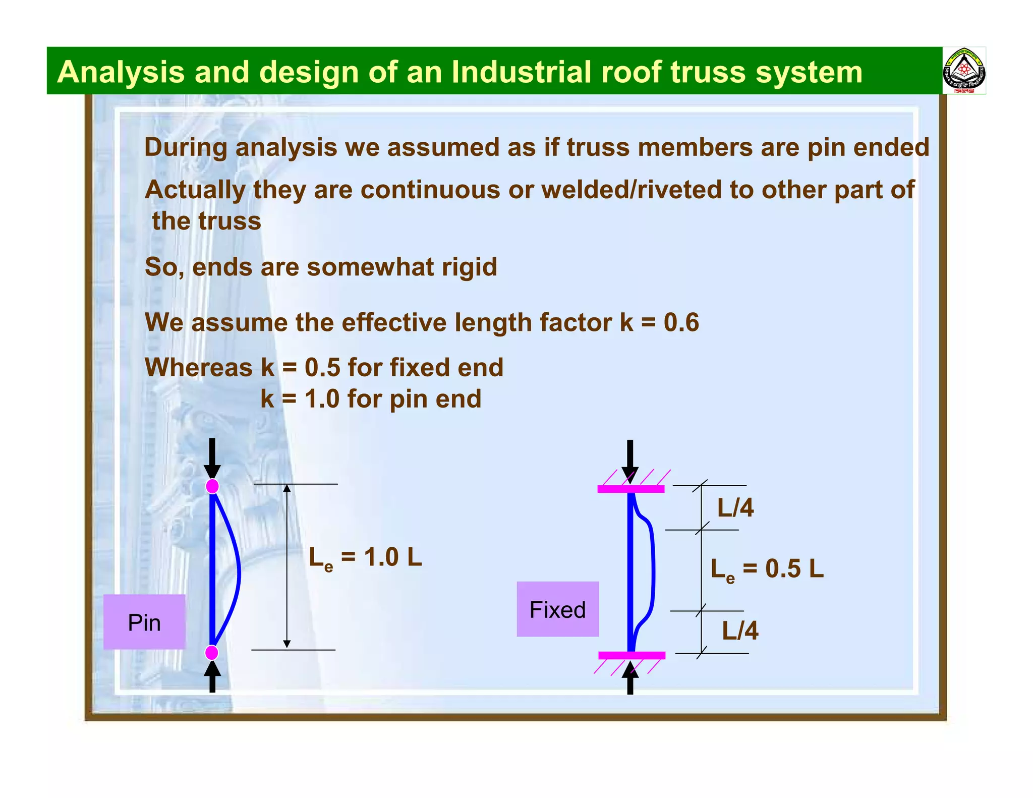
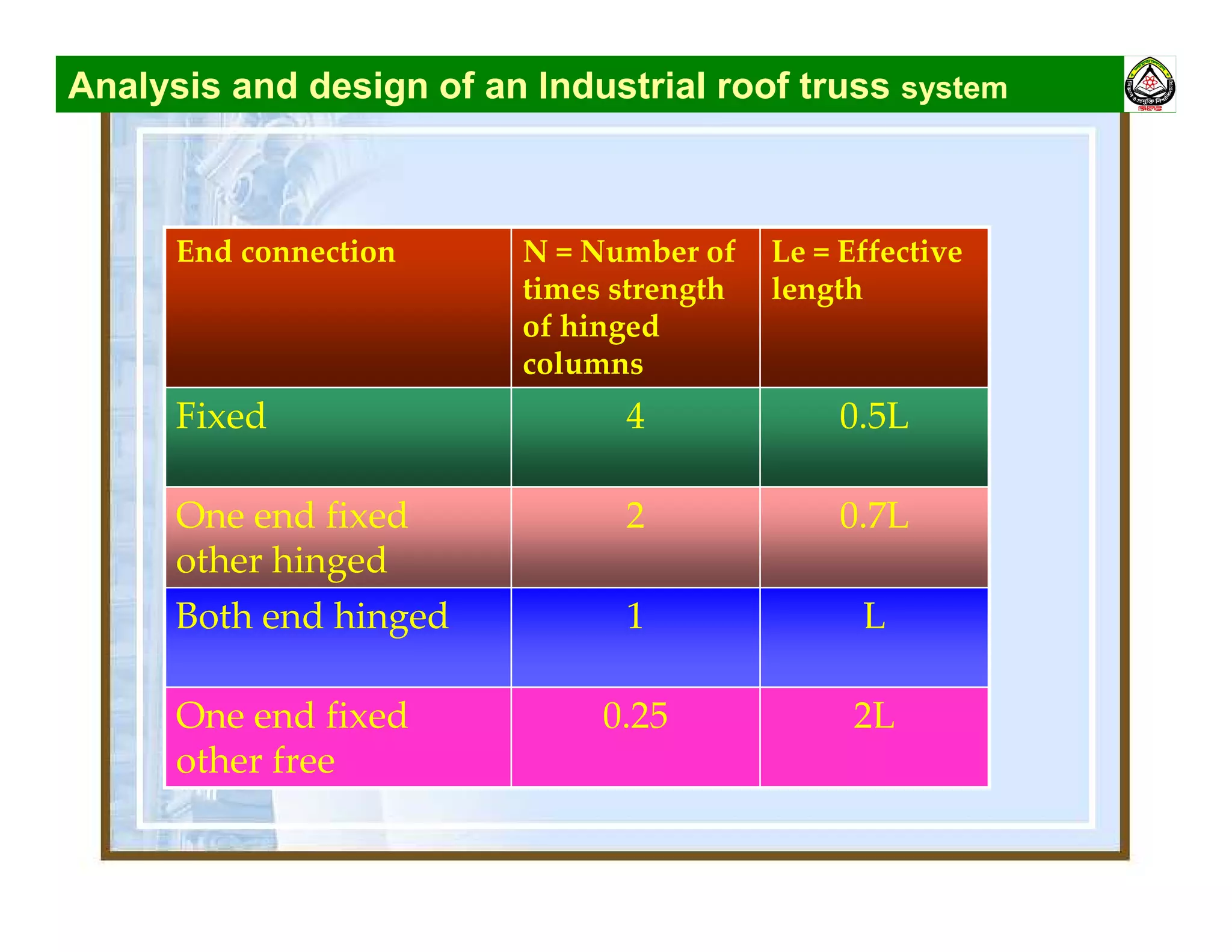
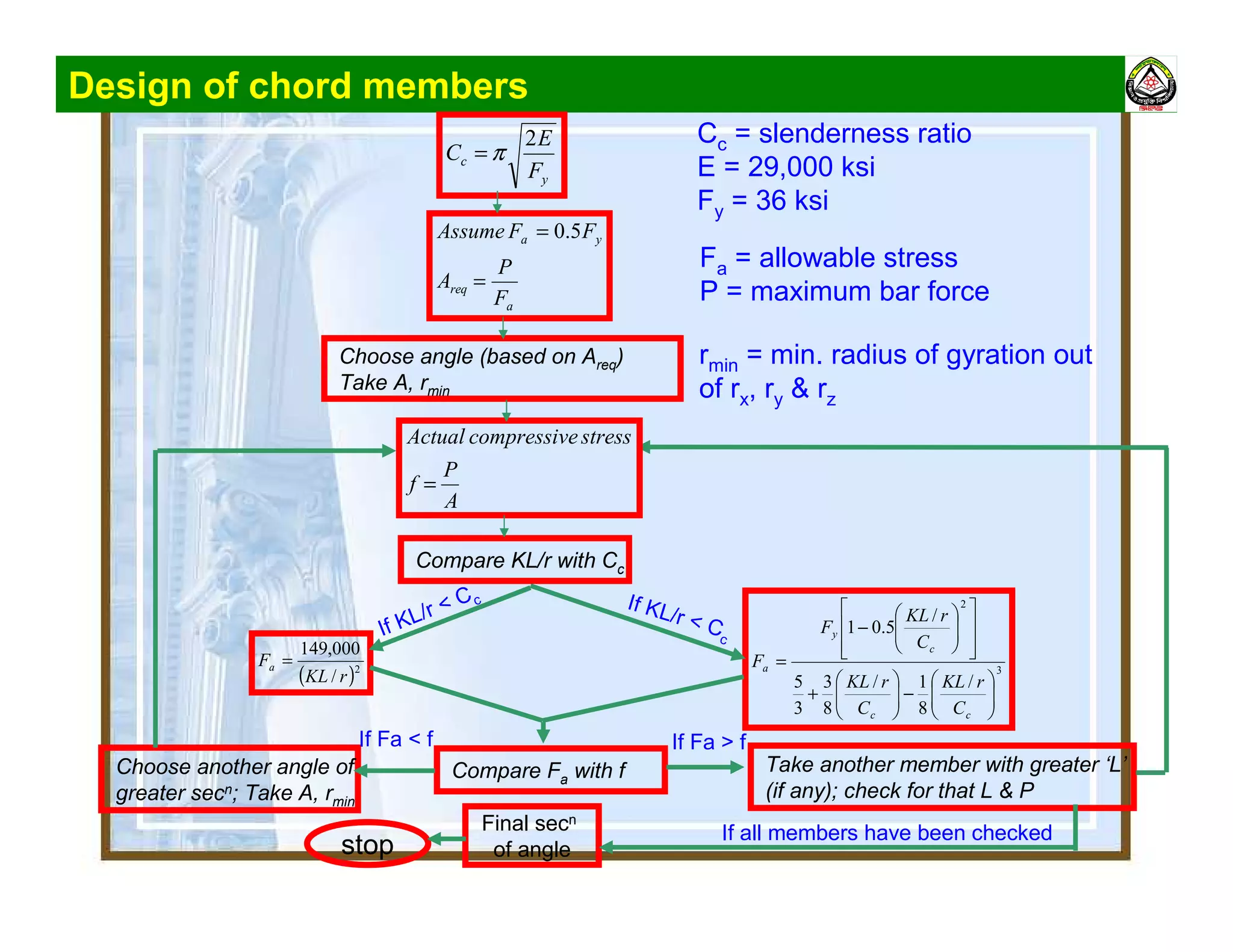
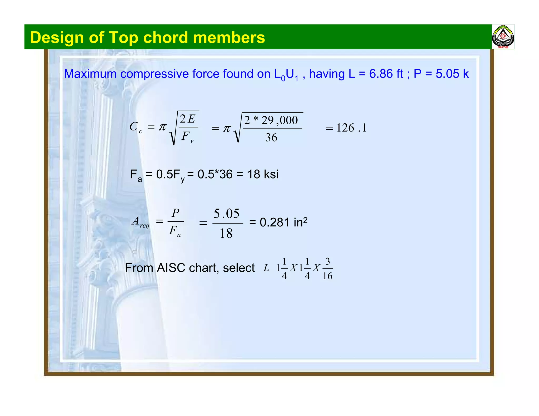
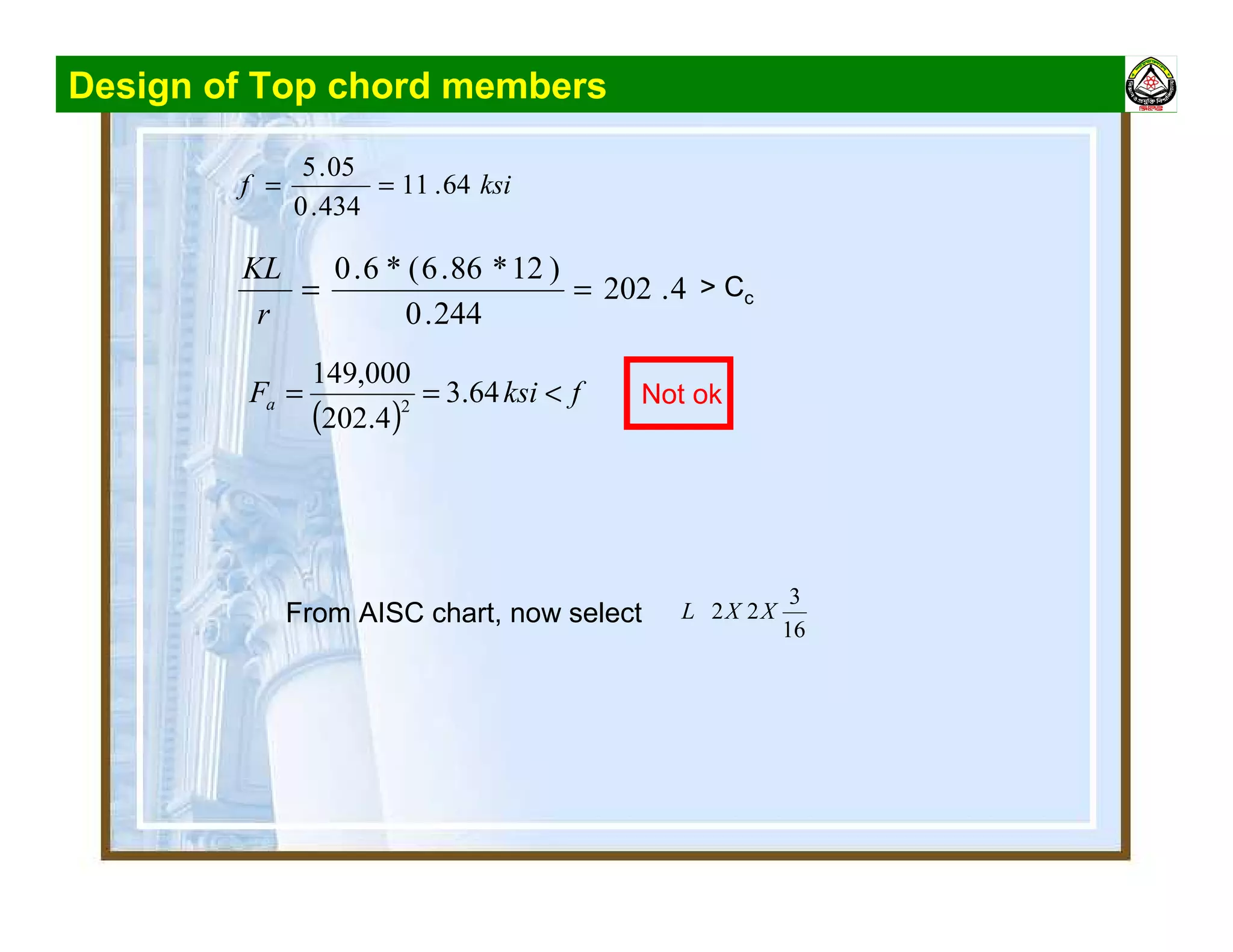
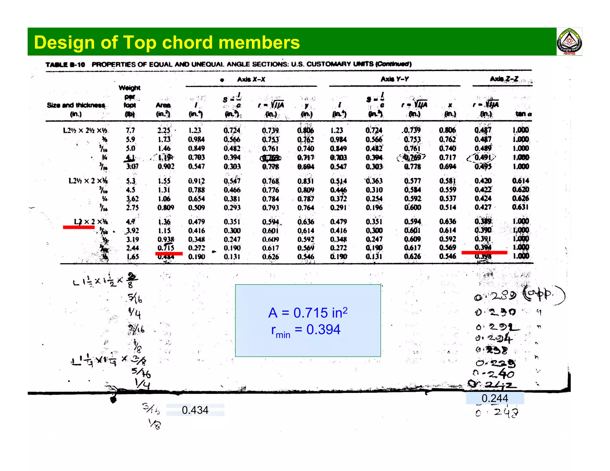
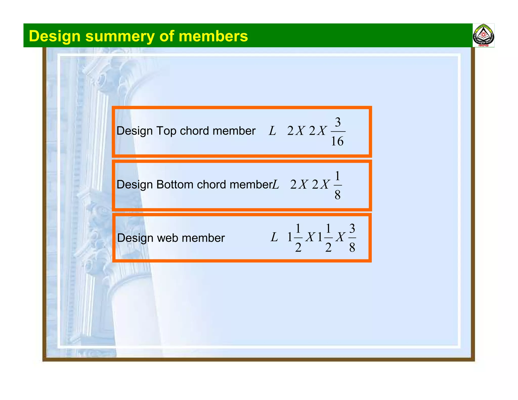
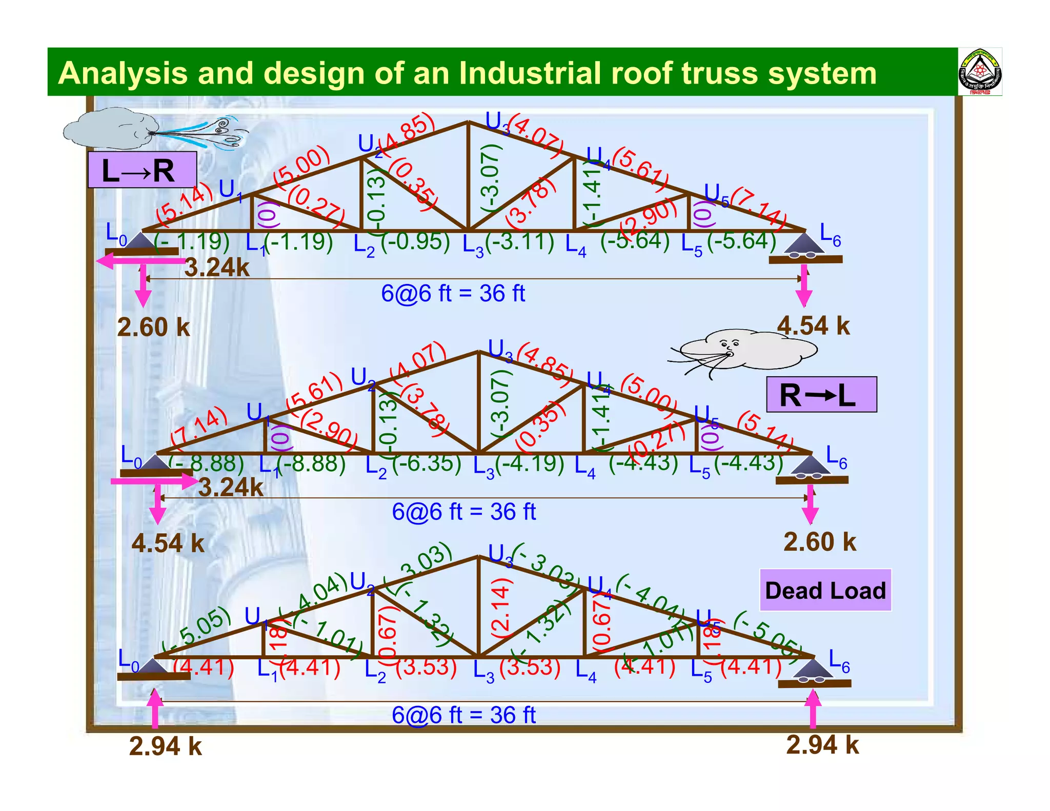
The document summarizes the structural analysis and design of an industrial roof truss system. It includes analysis of the truss under different load combinations, calculation of member forces, and design of the chord and web members. Key steps shown are determination of effective length factors, selection of member sections based on required area, and checking slenderness ratios and allowable stresses.

![Analysis and design of an Industrial roof truss system
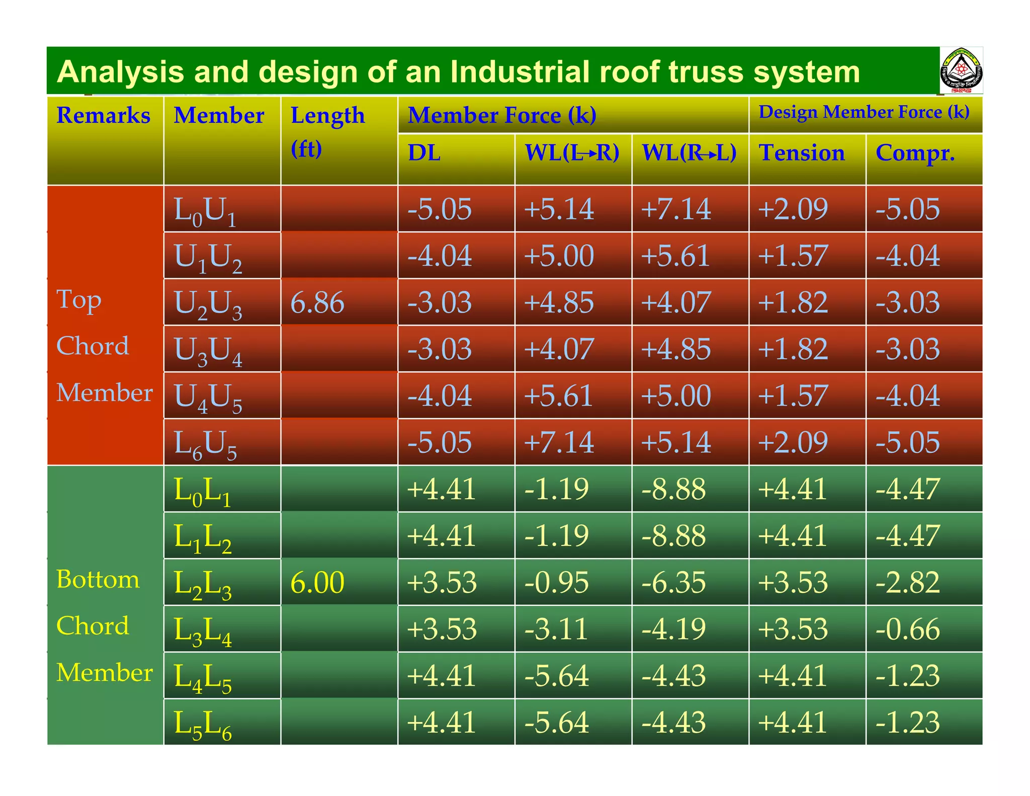
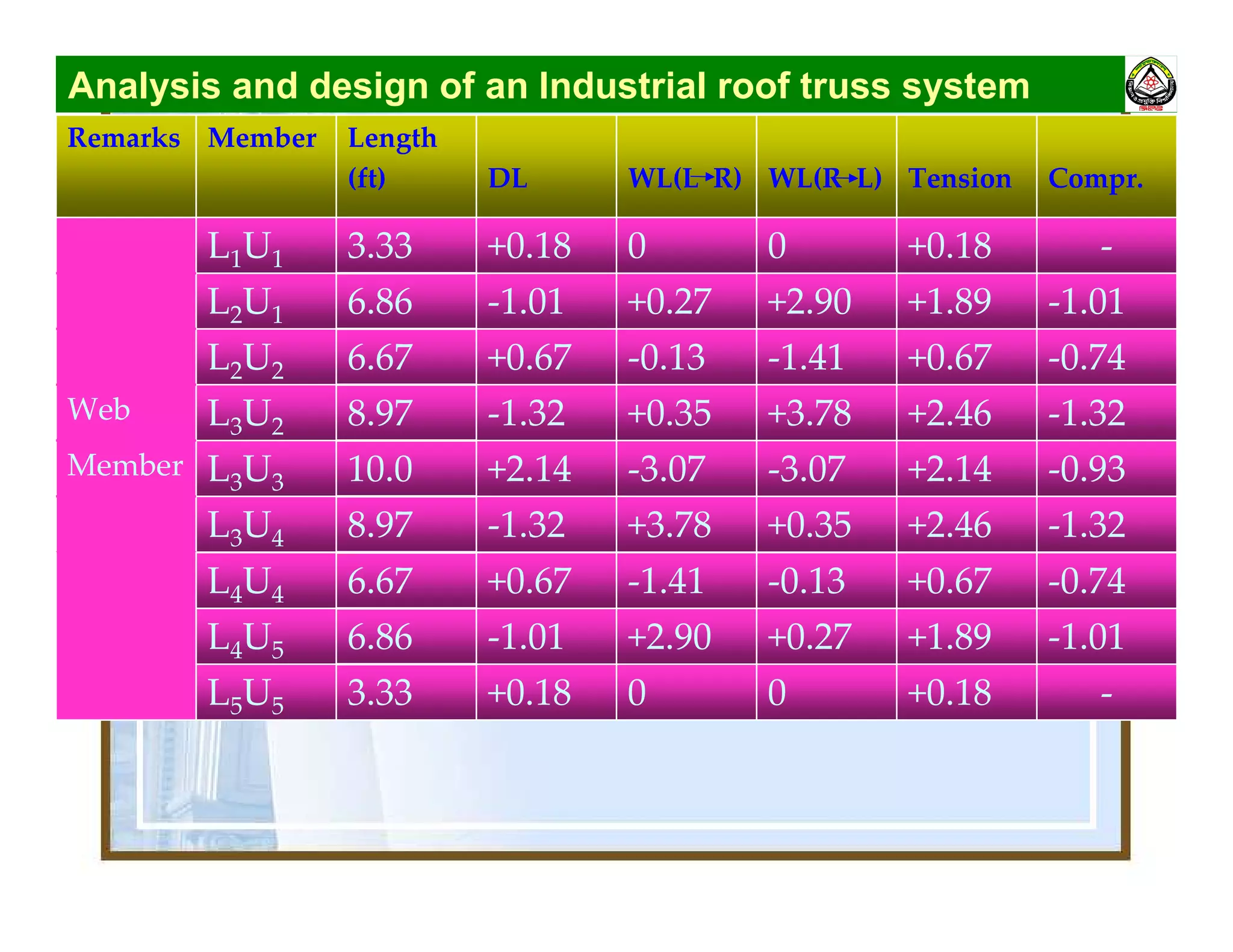
Load combinations
Condition 1: F1 = DL [No wind]
Condition 2: F2 = DL + WL (L→R)
Dead Load →DL
Wind Load →WL
Condition 3: F3 = DL + WL (R→L)
For design compressive force → Minimum of F1, F2 & F3 (If
positive leave it !)
For design tensile force → Maximum of F1, F2 & F3 (If
negative leave it !)](https://image.slidesharecdn.com/cee-3126-150501215545-conversion-gate02/75/Cee-312-6-structural-analysis-3-2048.jpg)