Installation of CCTVcamera
And
DVR Network Configuration
alexander.Leakemariam@etu.edu.et
2.
Video surveillance systemsmonitor
activities in public areas, businesses or
commercial buildings for real-time or later
review.
With the help of digital storage you can
identify people and provide evidences that
a series of events has occurred.
Video surveillance improves security and
safety ,and is used today in sectors ranging
from retail to industrial complexes and
other types of buildings.
Integrated electronic security system
3.
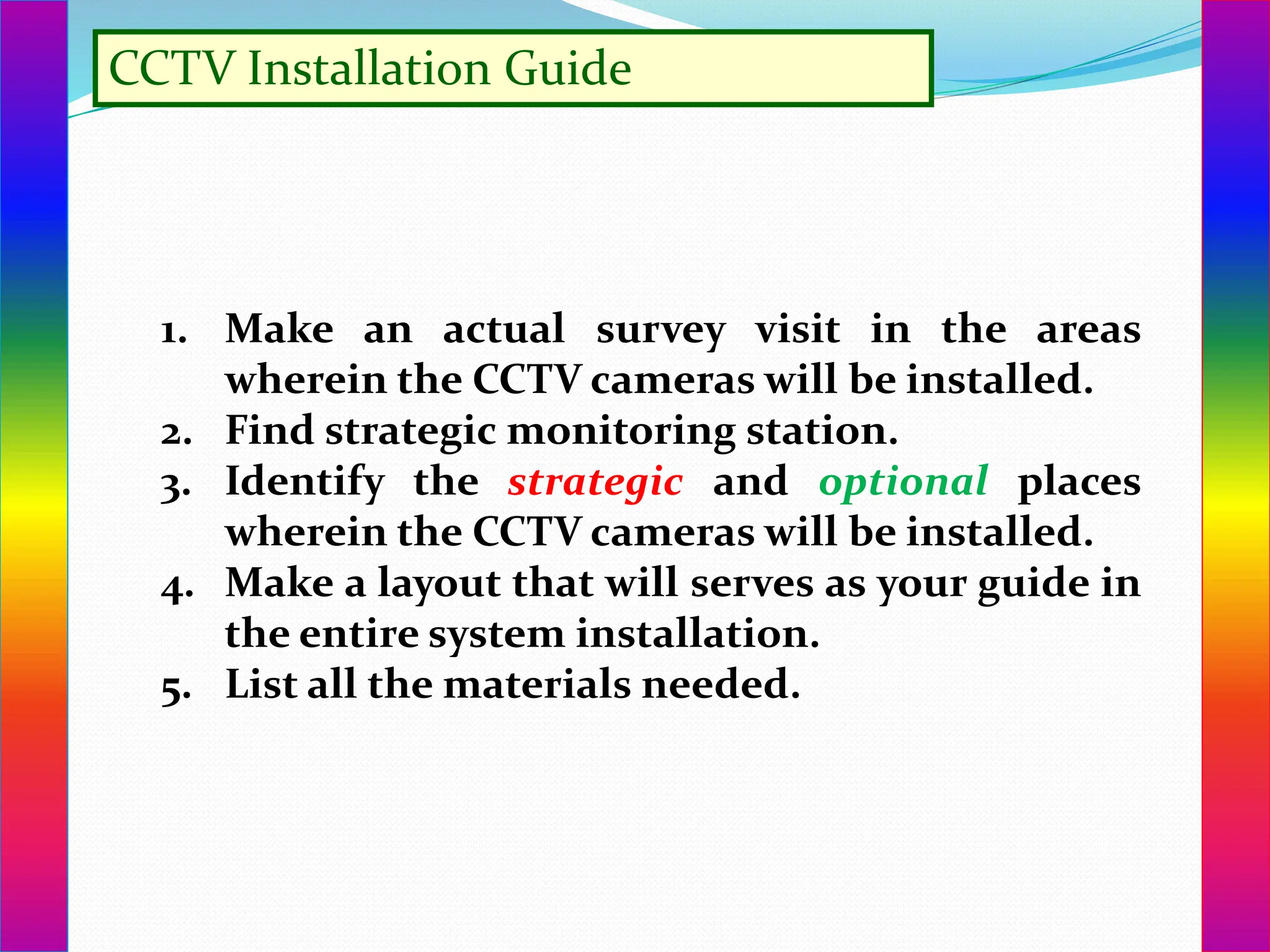
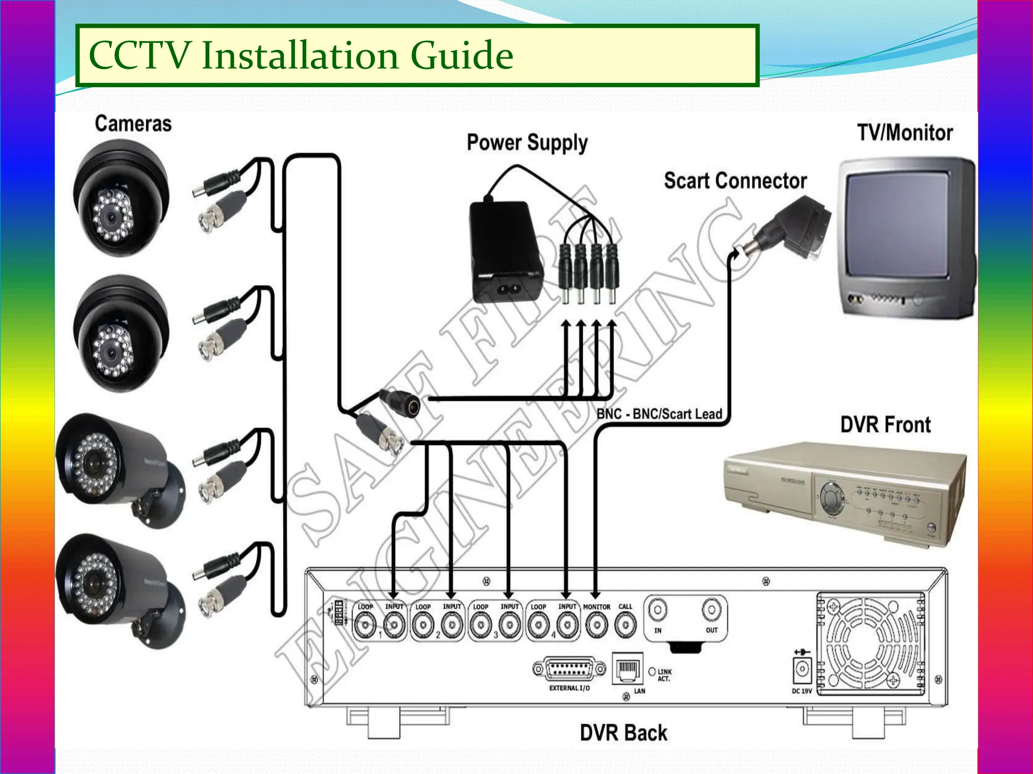
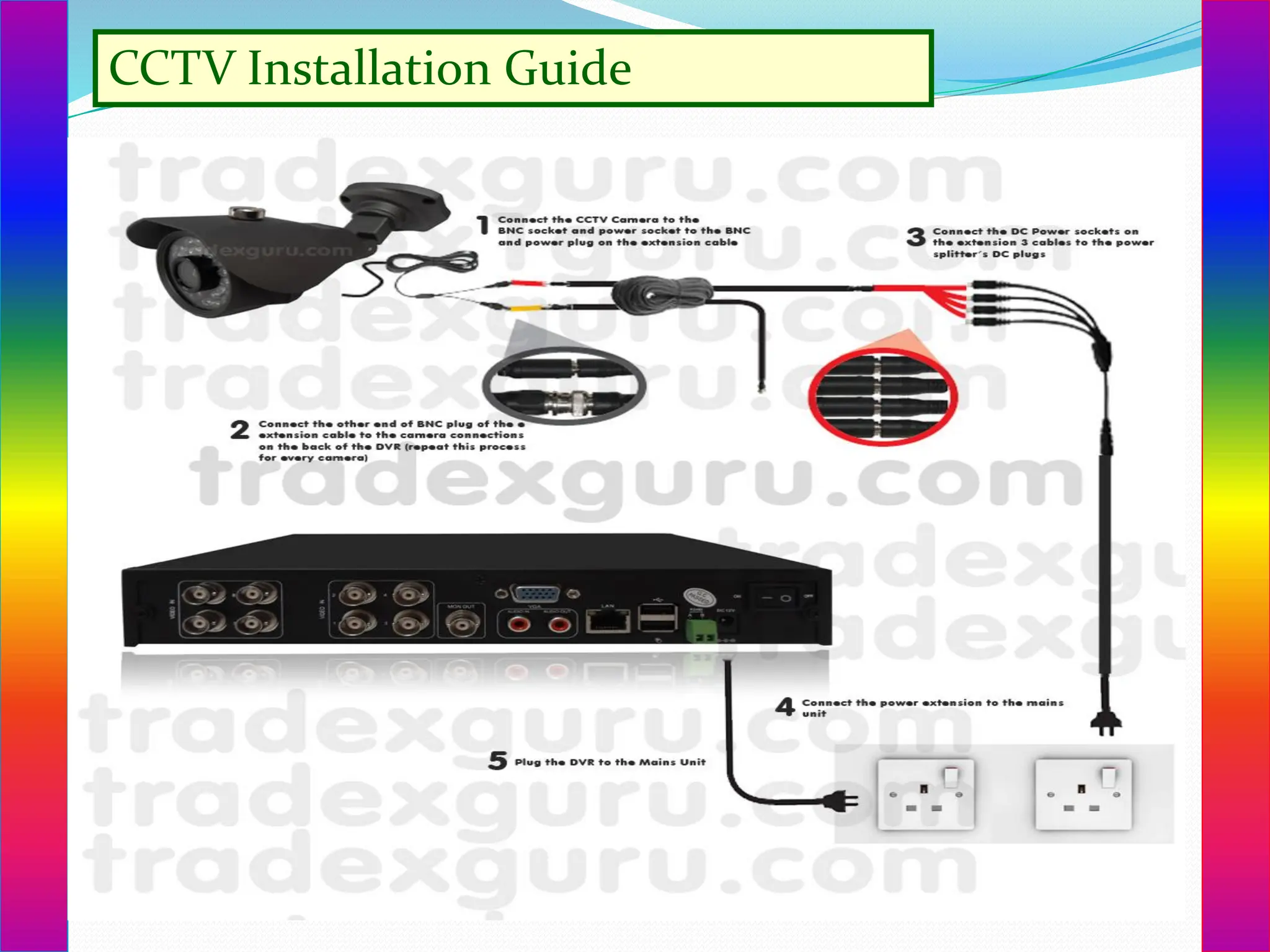
CCTV Installation Guide
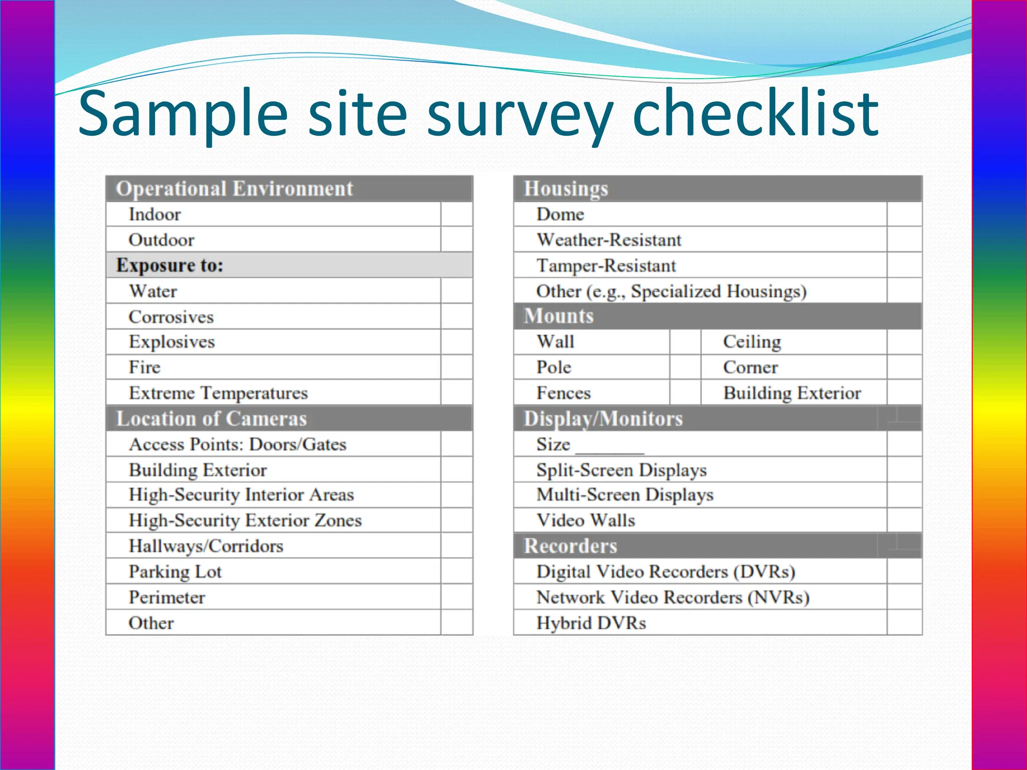
1.Make an actual survey visit in the areas
wherein the CCTV cameras will be installed.
2. Find strategic monitoring station.
3. Identify the strategic and optional places
wherein the CCTV cameras will be installed.
4. Make a layout that will serves as your guide in
the entire system installation.
5. List all the materials needed.
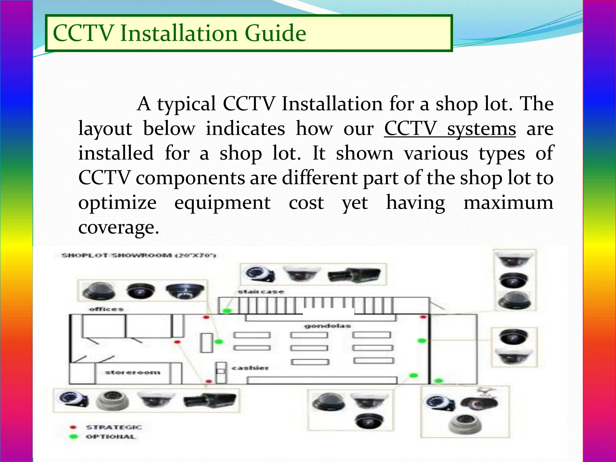
CCTV Installation Guide
Atypical CCTV Installation for a shop lot. The
layout below indicates how our CCTV systems are
installed for a shop lot. It shown various types of
CCTV components are different part of the shop lot to
optimize equipment cost yet having maximum
coverage.
7.
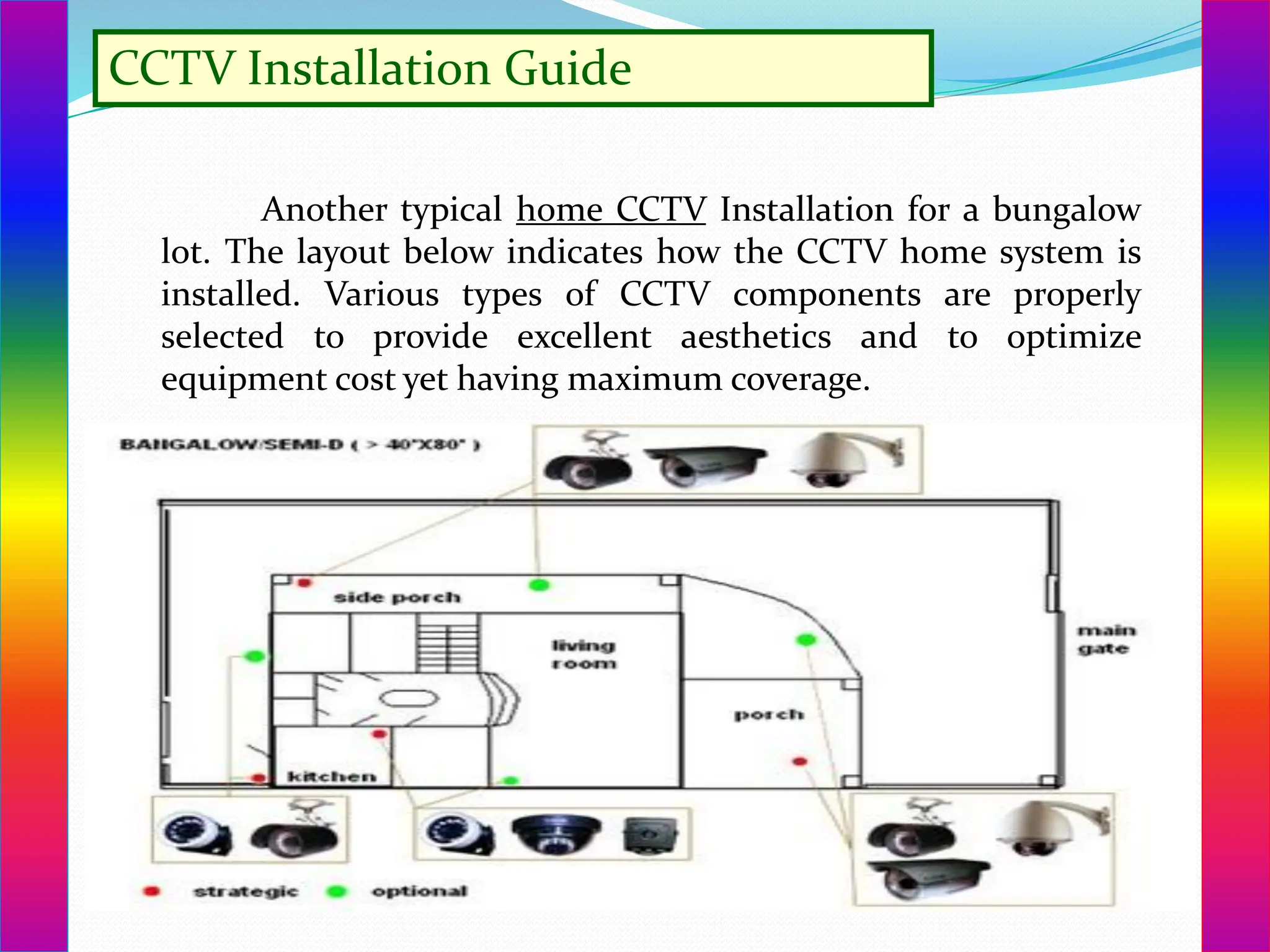
CCTV Installation Guide
Anothertypical home CCTV Installation for a bungalow
lot. The layout below indicates how the CCTV home system is
installed. Various types of CCTV components are properly
selected to provide excellent aesthetics and to optimize
equipment cost yet having maximum coverage.
8.
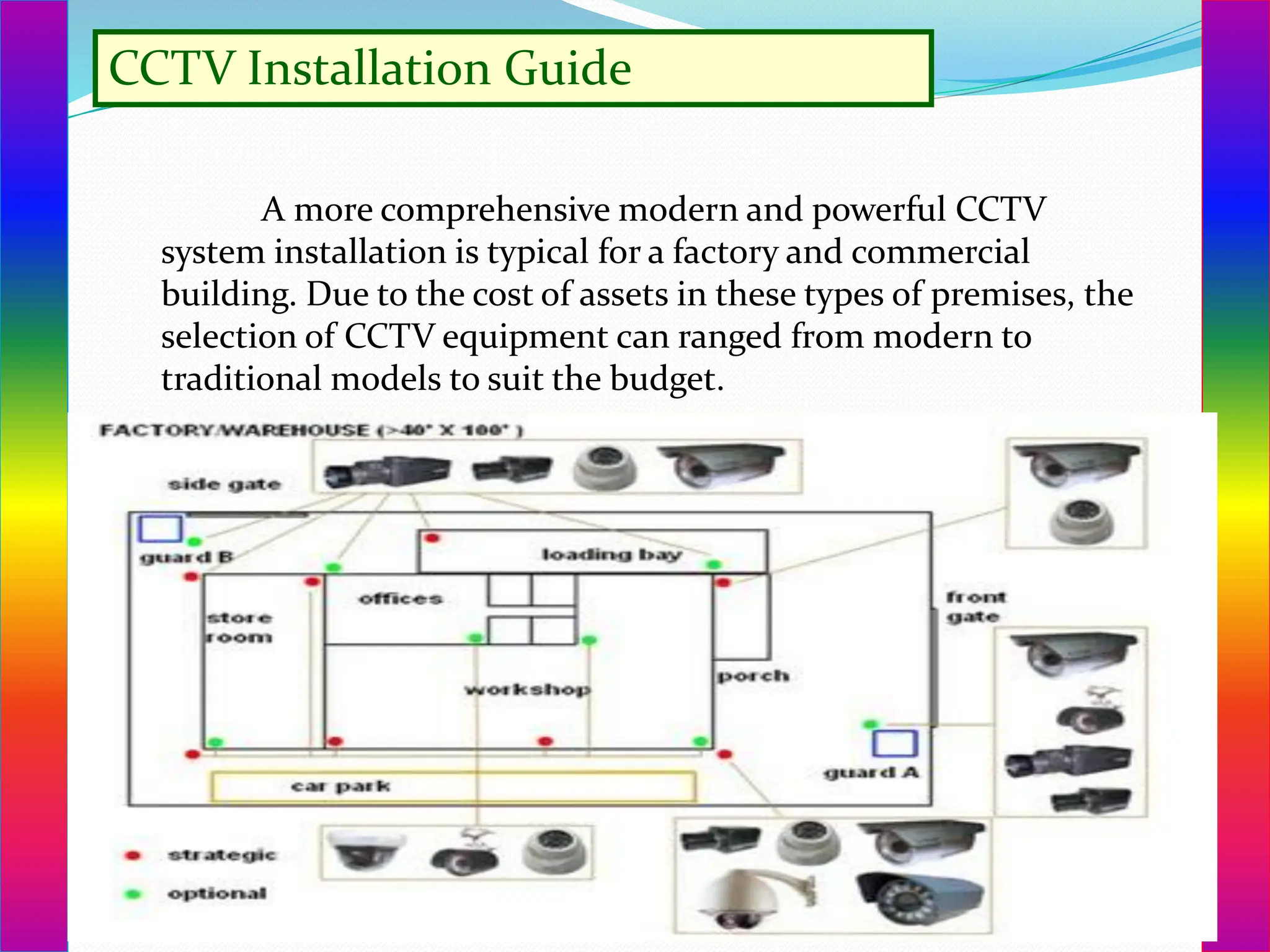
CCTV Installation Guide
Amore comprehensive modern and powerful CCTV
system installation is typical for a factory and commercial
building. Due to the cost of assets in these types of premises, the
selection of CCTV equipment can ranged from modern to
traditional models to suit the budget.
Introduction :installation ofCCTV camera
This procedure covers the following
installation and configuration areas.
System Installation – The physical cabling
and connections to install the system
System Configuration – Configuring DVR
and router to meet the customer’s
requirements
Special Camera – Installing PTZ and/or IDN
cameras
External TV Monitor – Setting up remote TV
monitoring of a single camera or the DVR
System Installation
12.
Cable Connections andAssembly
The first step in installing the video
surveillance system is running the
Siamese cable between the various
camera locations and the DVR.
The following procedure gives you step
by step instructions on how to
terminate the Siamese cable for both
the video portion (RG59 coaxial cable
with BNC connectors) and the power
portion (18 AWG Black and Red or
Black and White pair).
13.
Assemble tools andconnectors
Tools Required
➢RG-59 Crimp Tool
➢Diagonal Cutters
➢Knife
➢BNC Connectors & Sleeves (2 per
camera)
➢1 at camera location & 1 at DVR
location
15.
Split the power(black & white or
black & red) pair away from the
RG59 coaxial cable for about 6
inches at the camera location.
At the DVR location the split will
need to be enough to connect the
RG59 coaxial cable to the DVR and
the power pair to the Power
Distribution Unit.
17.
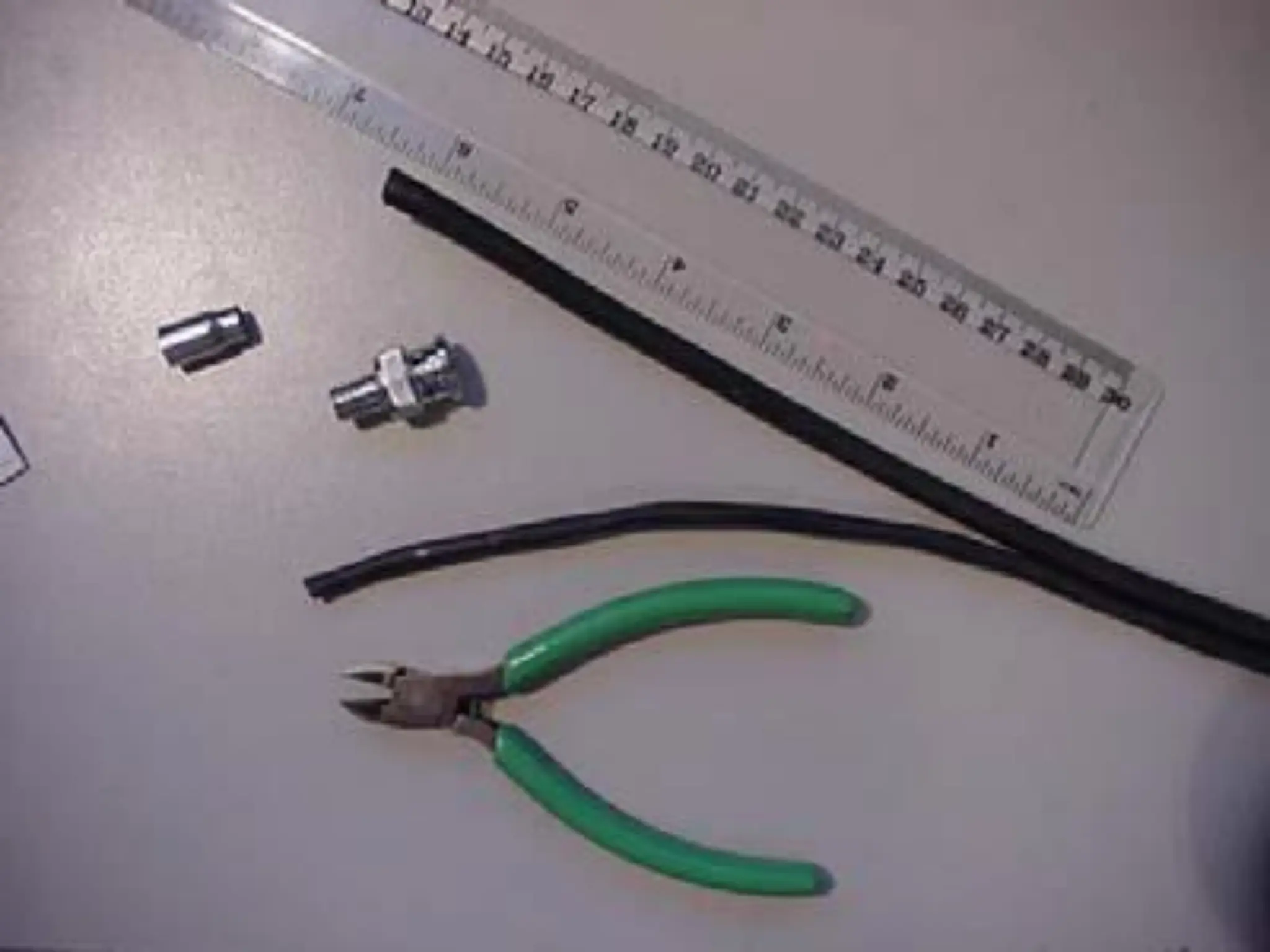
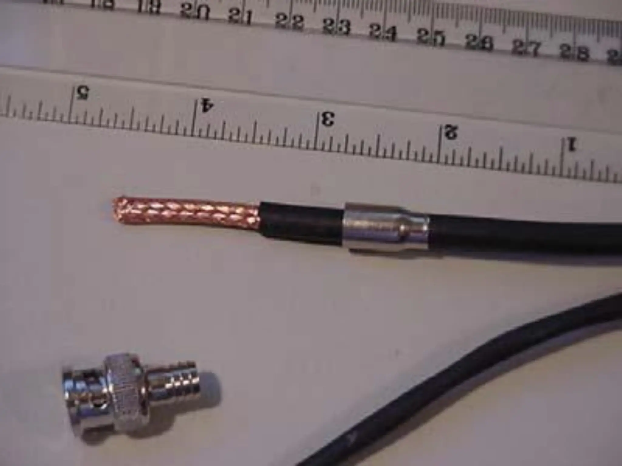
Insert the metalsleeve over the
RG59 coaxial cable.
Cut approximately 1 inch of the
outer shell from the cable exposing
the copper shield.
Please NOTE: The narrow/smaller
end of the sleeve needs to be
inserted over the RG59 cable
FIRST!
Use the knifeto carefully
trim back the inner
insulator around the copper
center wire. You should
leave about 1/16 to 1/8 inch
insulator beyond the shield.
The inner copper wire
should be about 1/2 inch
long.
22.
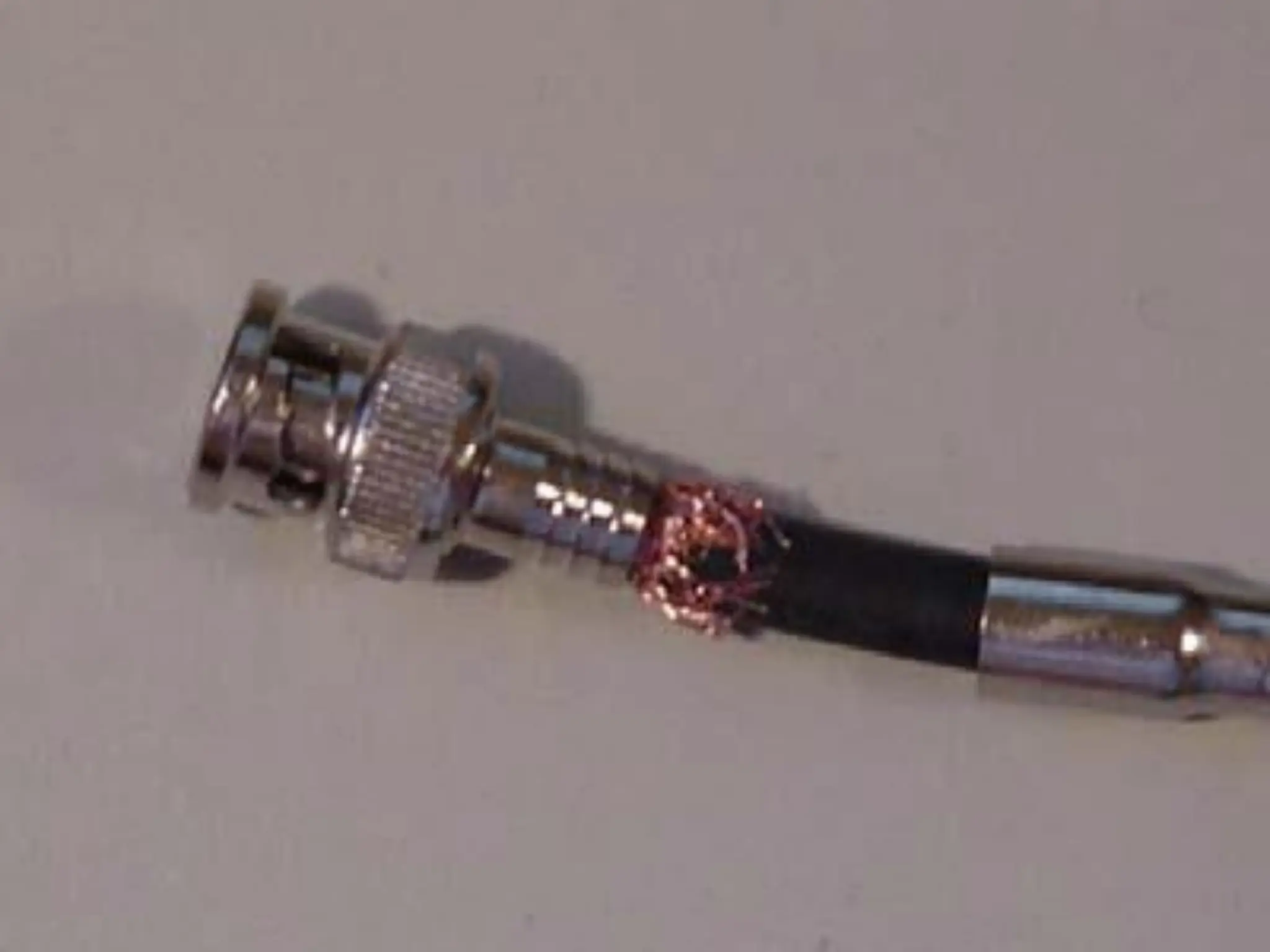
Carefully insert theBNC
connector over the inner
copper wire sliding it firmly
back towards the shield
portion until it is in place
and the shield is touching
the sleeve portion of the
connector.
24.
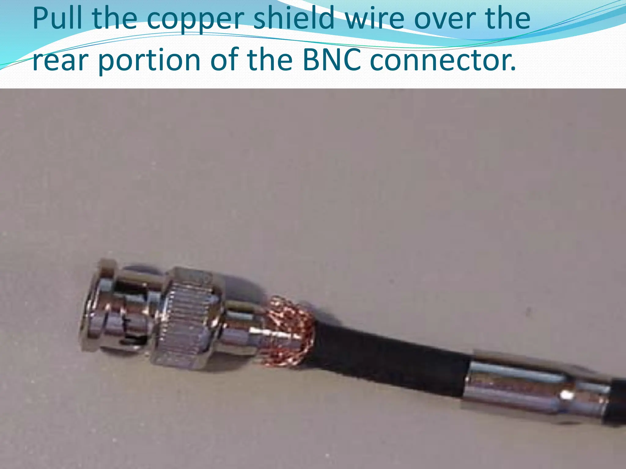
Pull the coppershield wire over the
rear portion of the BNC connector.
25.
Slide the metalsleeve up OVER the copper
shield. Ensure that you are securely holding
the BNC connector against the RG59 cable.
Often when you slide up the sleeve you will
push the connector away from the inner
core wire unless you are holding it securely.
26.
Crimp themetal sleeve onto the BNC connector
using the larger (inner die) of your crimp tool.
Now crimp the narrow end of the sleeve over the
RG59 cable using the smaller (outer die) of your
crimp tool.
Power wirepreparation.
Remove about two inches of the outer shield from
the power portion of the Siamese cable.
Remove about 3/8 inch insulation from each of
the wires.
29.
Power Connections
Beforewe start with power connections we need
to add a little information about camera types &
groups. There are two basic camera groups that
are used with video surveillance systems and each
has it’s own unique cabling and power issues.
The first camera group is modular cameras. The
modular cameras are the most versatile because
you have many different options to chose from
starting with the basic camera body (12 VDC, 24
VAC, color or black and white), then you can
select
30.
a lens(auto Iris, manual Iris, telephoto, standard, etc.),
and the mounting bracket (indoor, outdoor, color, etc.).
This is the more common option because the customer
can build a camera to meet his requirements for any
camera location.
The second group of cameras is the All-in-One (AIO)
versions. These cameras are normally 12 VDC but may
also be found with the 24 VAC option. The cameras that
fall into this group are domes cameras, bullet cameras,
day/night color/infrared, covert cameras and most of the
pan/tilt/zoom cameras. The lens, power connections and
mount are included as part of the basic camera and does
not normally require any assembly when they are
installed.
31.
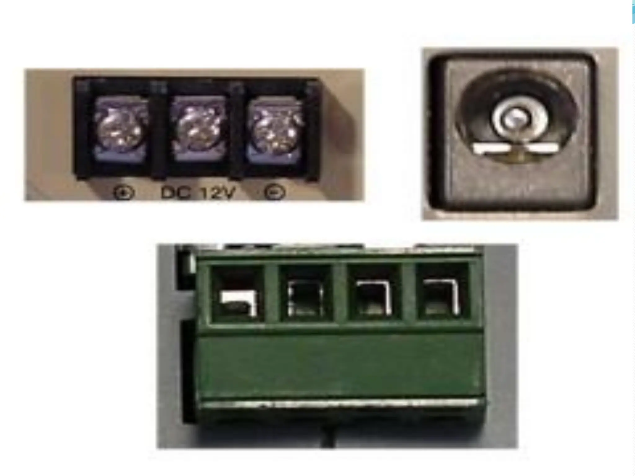
Connections forthe modular cameras will look similar to
the various connections shown at the right. These
cameras are powered either by 12 VDC or 24 VAC.
If the camera is a 12 VDC camera it is imperative that the
power cables be connected to the proper terminals.
If the camera is a 12 VDC camera it is imperative that the
power cables be connected to the proper terminals.
The BLACK power lead is always connected to the
Negative (-) terminal of the camera and the WHITE (or
RED) power lead to the Positive (+) terminal of the
camera.
Although it is not required, the same process is
recommended for 24 VAC cameras to ensure continuity
when connecting up the system.
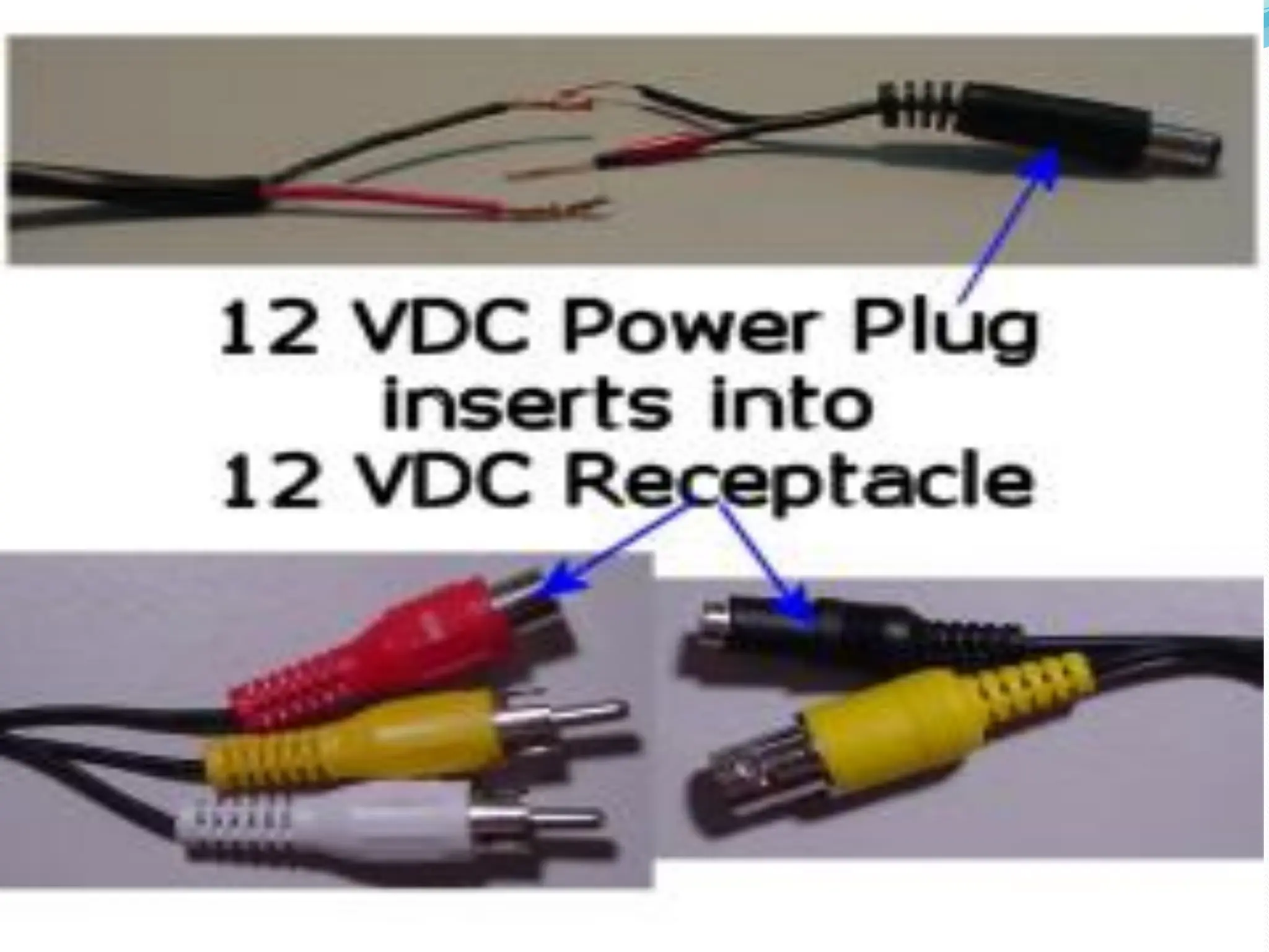
33.
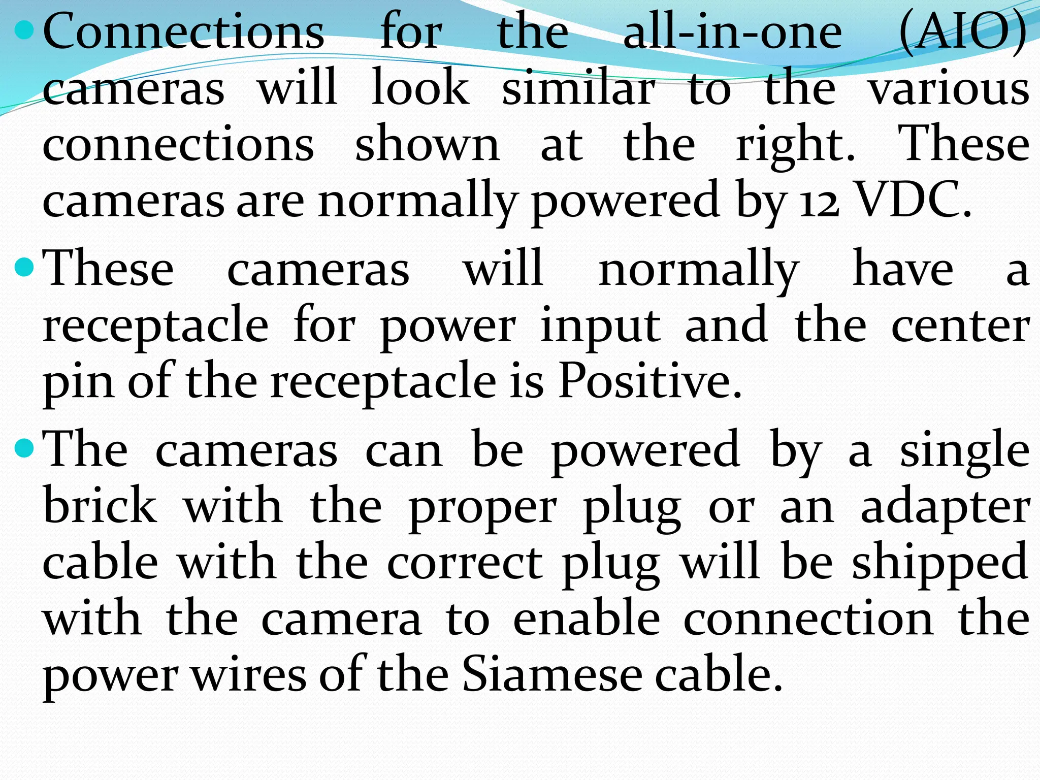
Connections for theall-in-one (AIO)
cameras will look similar to the various
connections shown at the right. These
cameras are normally powered by 12 VDC.
These cameras will normally have a
receptacle for power input and the center
pin of the receptacle is Positive.
The cameras can be powered by a single
brick with the proper plug or an adapter
cable with the correct plug will be shipped
with the camera to enable connection the
power wires of the Siamese cable.
35.
If the camerarequires 12 VDC, the power
source MUST be connected to the proper
terminals.
The BLACK power lead is always
connected to the Negative (-) terminal of
the camera and the WHITE (or RED)
power lead to the Positive (+) terminal of
the camera.
Although it is not required, the same
process is recommended for 24 VAC
cameras to ensure continuity when
connecting up the system.
37.
Connections forthe all-in-one (AIO) cameras will
look similar to the various connections shown at
the right. These cameras are normally powered by
12 VDC.
These cameras will normally have a receptacle for
power input and the center pin of the receptacle
is Positive.
The cameras can be powered by a single brick
with the proper plug or an adapter cable with the
correct plug that is shipped with the camera to
enable connection the power wires of the Siamese
cable.
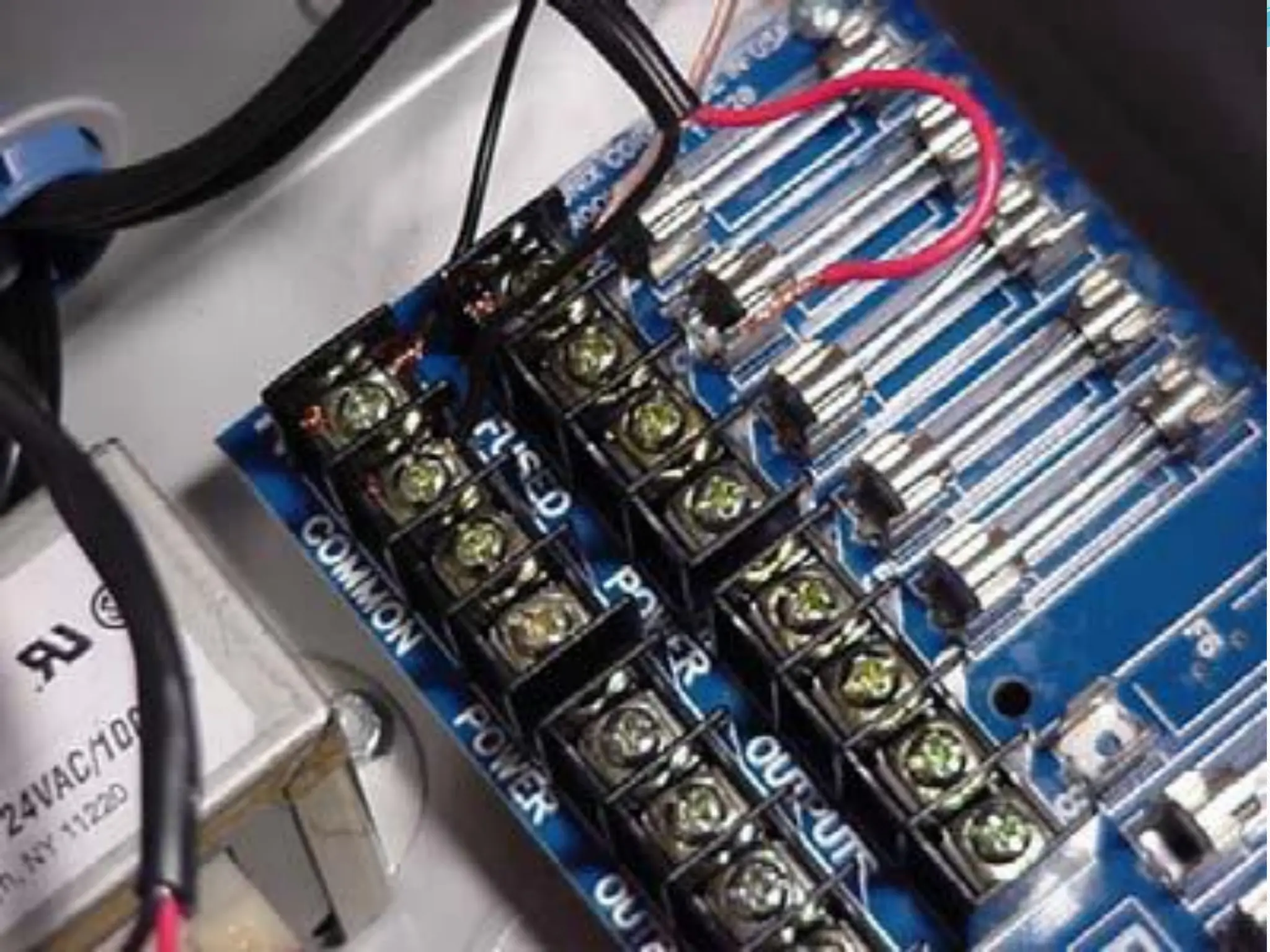
39.
There are twooptions for power
connections at the DVR end of the cable.
A Power Distribution Unit (PDU) or a single
power source (commonly called a brick) for
each camera. Both type of power sources
come in 12 VDC and 24 VAC version.
A 24VAC version of the PDU is shown. All
connections are identical for both versions.
Black wires are connected to the Negative or
Common connection and the White (or
Red) wire to the Positive connection.
41.
Camera Assembly(Modular Cameras) and
Installation
The next step is to assemble the modular cameras and
then install the cameras in the locations indicated by the
customer. Modular cameras will require assembly of a
lens and mounting bracket prior to installation. The all-
in-one cameras are completely assembled during
manufacturing and will require only installation and
connection to the DVR and power.
Most modular cameras are similar to the 12 VDC camera
used for this example. If you have any questions about
any assembly instructions for the version of camera that
you have received, please called VS Technical Support for
assistance.
42.
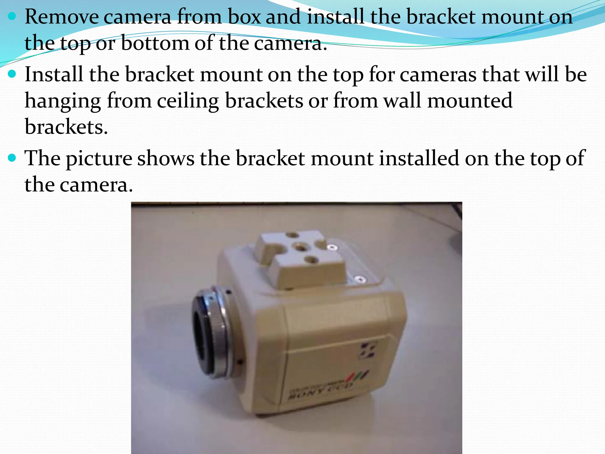
Remove camerafrom box and install the bracket mount on
the top or bottom of the camera.
Install the bracket mount on the top for cameras that will be
hanging from ceiling brackets or from wall mounted
brackets.
The picture shows the bracket mount installed on the top of
the camera.
43.
Some cameraswill have a larger silver ring to
mount “C” type camera lenses. Look at the
camera documentation to determine if the “C”
mounting ring has been included with the
camera. This ring is rarely used and is not
required for the lenses shipped for this
installation. If this ring has been included it must
be removed before installing the lens.
44.
Insert thelens into the mounting bracket on the camera.
Rotate the lens until it has been screwed in
completely and snugly.
Ensure the lens is inserted tightly but DO NOT
over tighten as you could strip the lens threads.
Insert the auto-iris cable into the back of the
camera.
45.
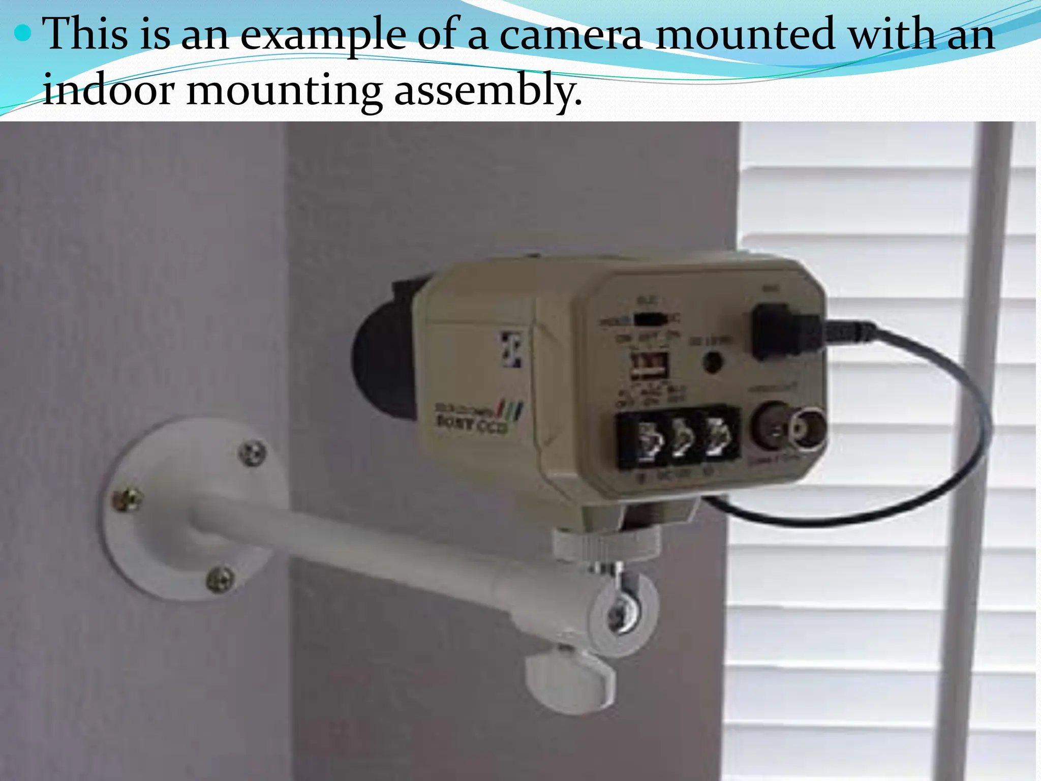
This isan example of a camera mounted with an
indoor mounting assembly.
46.
After the camerahas been mounted connect
the power wires to the camera.
Connect the Black (common/negative) wire
to the Negative ( - ) terminal on the camera.
Connect the Red or White (hot/positive)
wire to the Positive ( + ) terminal on the
back of the camera.
If you are using a single power source or
“Brick” that has been shipped to you, one of
the wires on the brick will be labeled as
positive to indicate which wire is connected
to each terminal.
Camera installed.
After all the cameras have been installed we go to the
DVR to complete the power and video connections.
50.
KVM Installationand Connections (Optional)
Now that the cameras have been assembled, mounted
and connected, the next portion of the installation will
be the cabling and setup of the digital video recorder or
DVR.
To begin with the DVR is similar to a personal computer
and will require a keyboard, mouse and a monitor to
operate.. Most customers have a keyboard, mouse and
monitor that they are using with their current point-of-
sale (POS) system or they already have a PC that they are
working with. Due to space restrictions, we normally
install a KVM (Keyboard, Video, Mouse) switch that will
allow the customer to switch from the DVR to his
POS/PC system and use his current keyboard, mouse
and monitor to control and operate both the DVR and
his POS/PC system.
51.
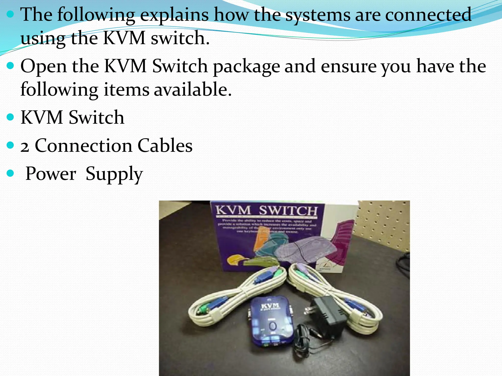
The followingexplains how the systems are connected
using the KVM switch.
Open the KVM Switch package and ensure you have the
following items available.
KVM Switch
2 Connection Cables
Power Supply
52.
Select oneof the KVM Cables and connect the Keyboard
(purple PS-2 type connector), Video (blue DB15
connector) and Mouse (green PS-2 connector) to the
appropriate ports on the PC2 side of the KVM switch.
Connect the other end of the SAME cable to the
appropriate ports on the back of the DVR as shown at
the right.
NOTE: Ensure the Video (DB15 connector) is plugged
into the Video port on the DVR motherboard NOT one
of the video ports on the video card.
53.
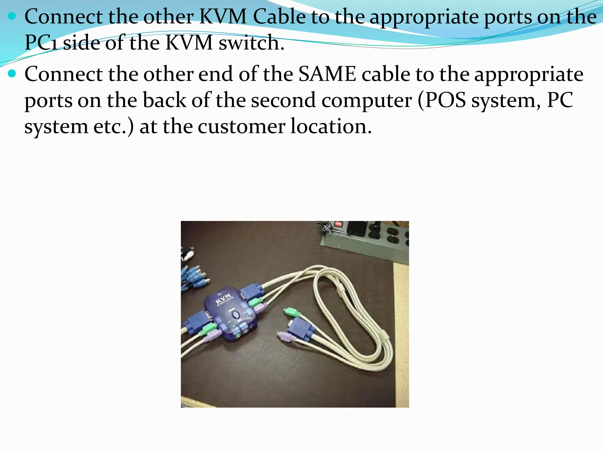
Connect theother KVM Cable to the appropriate ports on the
PC1 side of the KVM switch.
Connect the other end of the SAME cable to the appropriate
ports on the back of the second computer (POS system, PC
system etc.) at the customer location.
54.
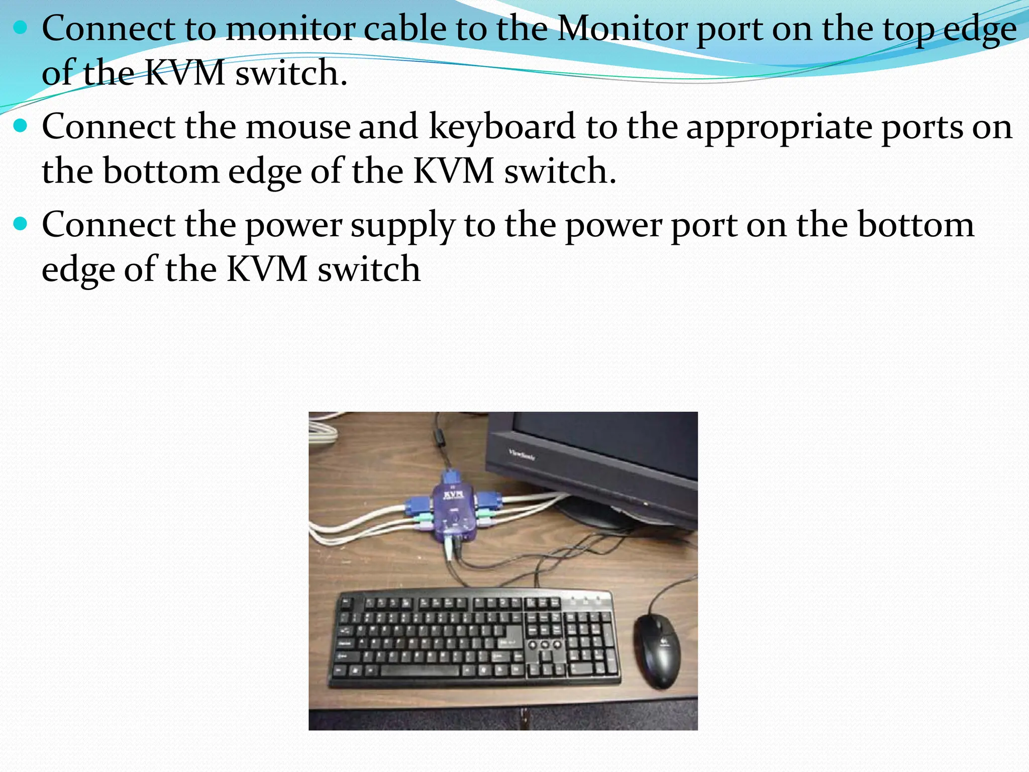
Connect tomonitor cable to the Monitor port on the top edge
of the KVM switch.
Connect the mouse and keyboard to the appropriate ports on
the bottom edge of the KVM switch.
Connect the power supply to the power port on the bottom
edge of the KVM switch
55.
With theKVM switch installed, you should be
able to hit the button on the top of the KVM
switch which will switch you from one system to
the other, and use his current keyboard, mouse
and monitor to control and operate both the DVR
and his POS/PC system.
56.
If you getan all-in-one security camera (system), screws-kind-of
necessary installation materials are usually included in the camera
box.
57.
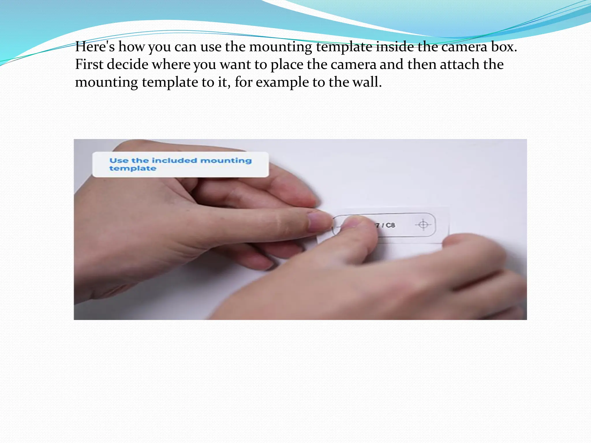
Here's how youcan use the mounting template inside the camera box.
First decide where you want to place the camera and then attach the
mounting template to it, for example to the wall.
58.
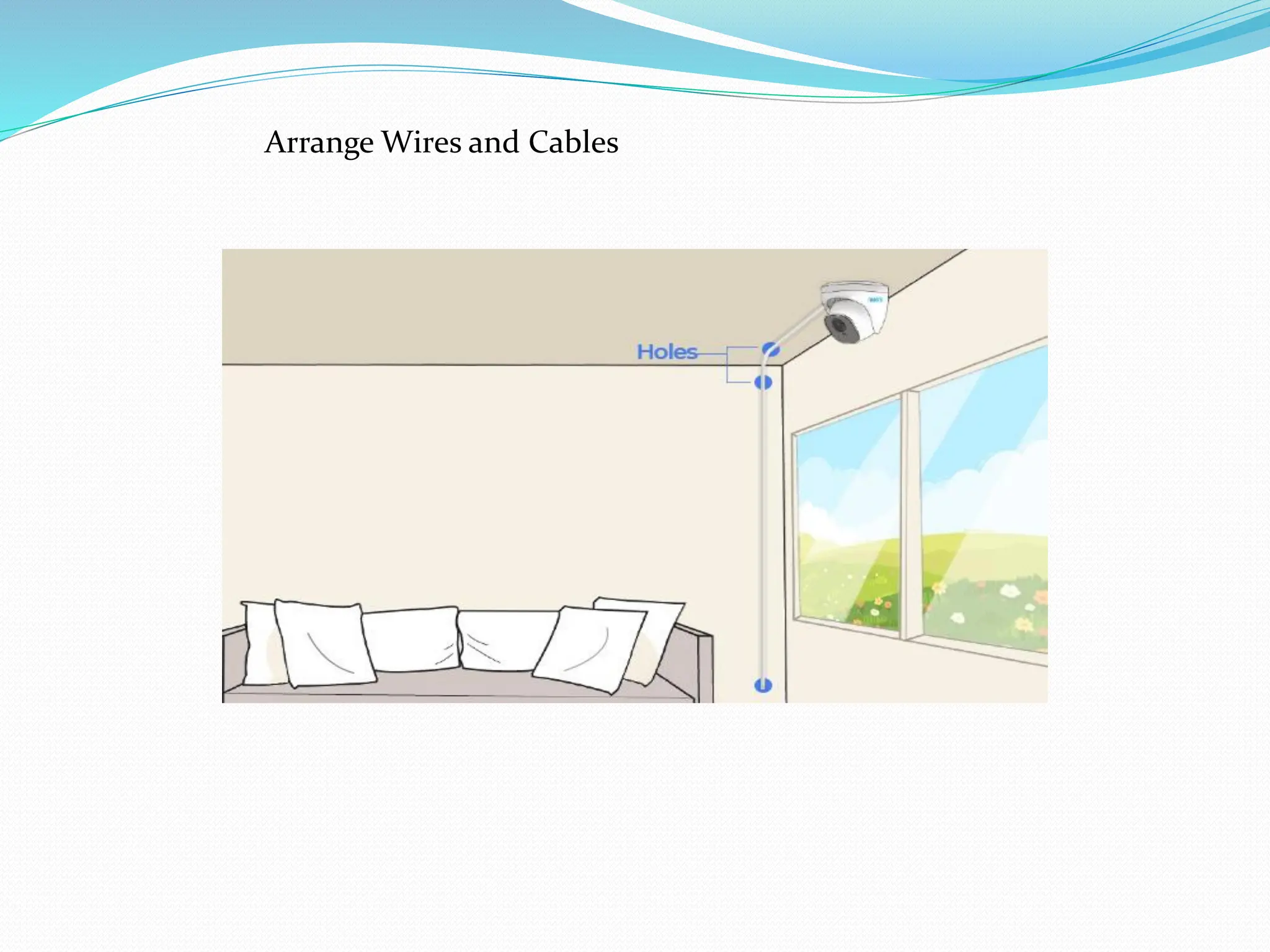
Then use adrill bit the same size as the screws that came with your camera to
drill pilot holes in each of the marked locations on the template.
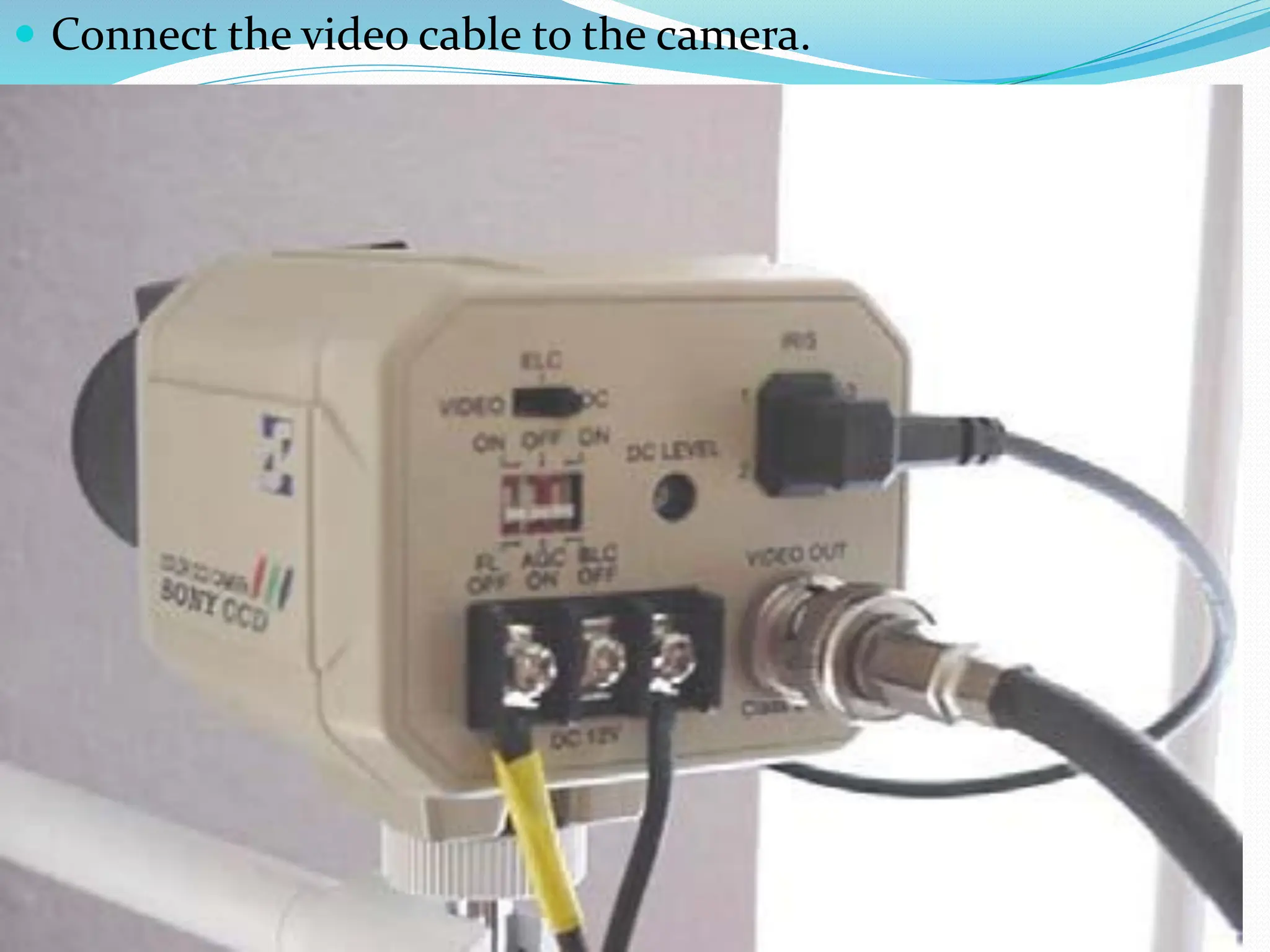
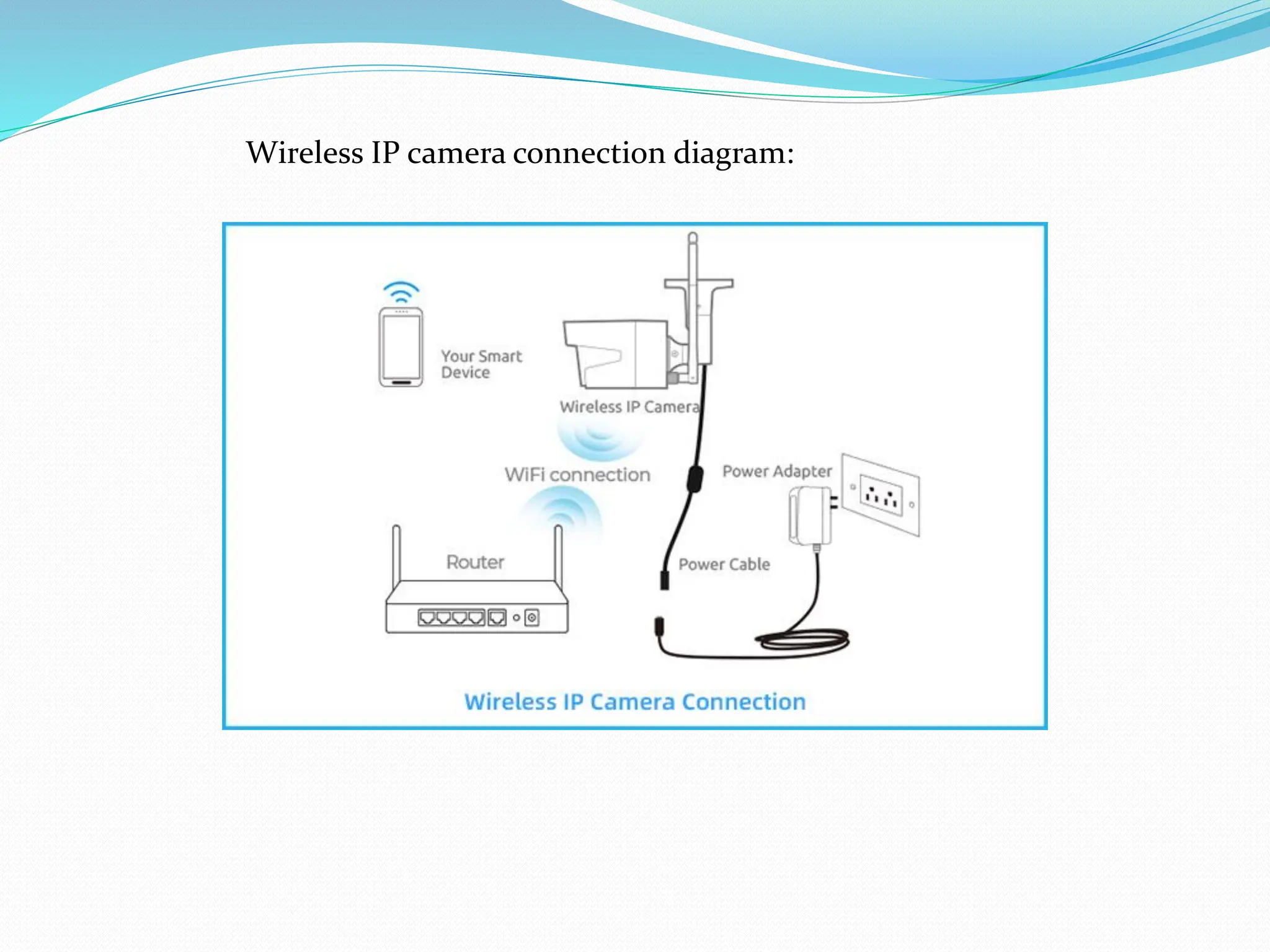
Connect Wires andPower On
After the wiring process, the next step is to connect your home CCTV security
camera and check if it can get power supply. Here we will share wire diagrams
about how to connect the camera, including wired and wireless cameras.
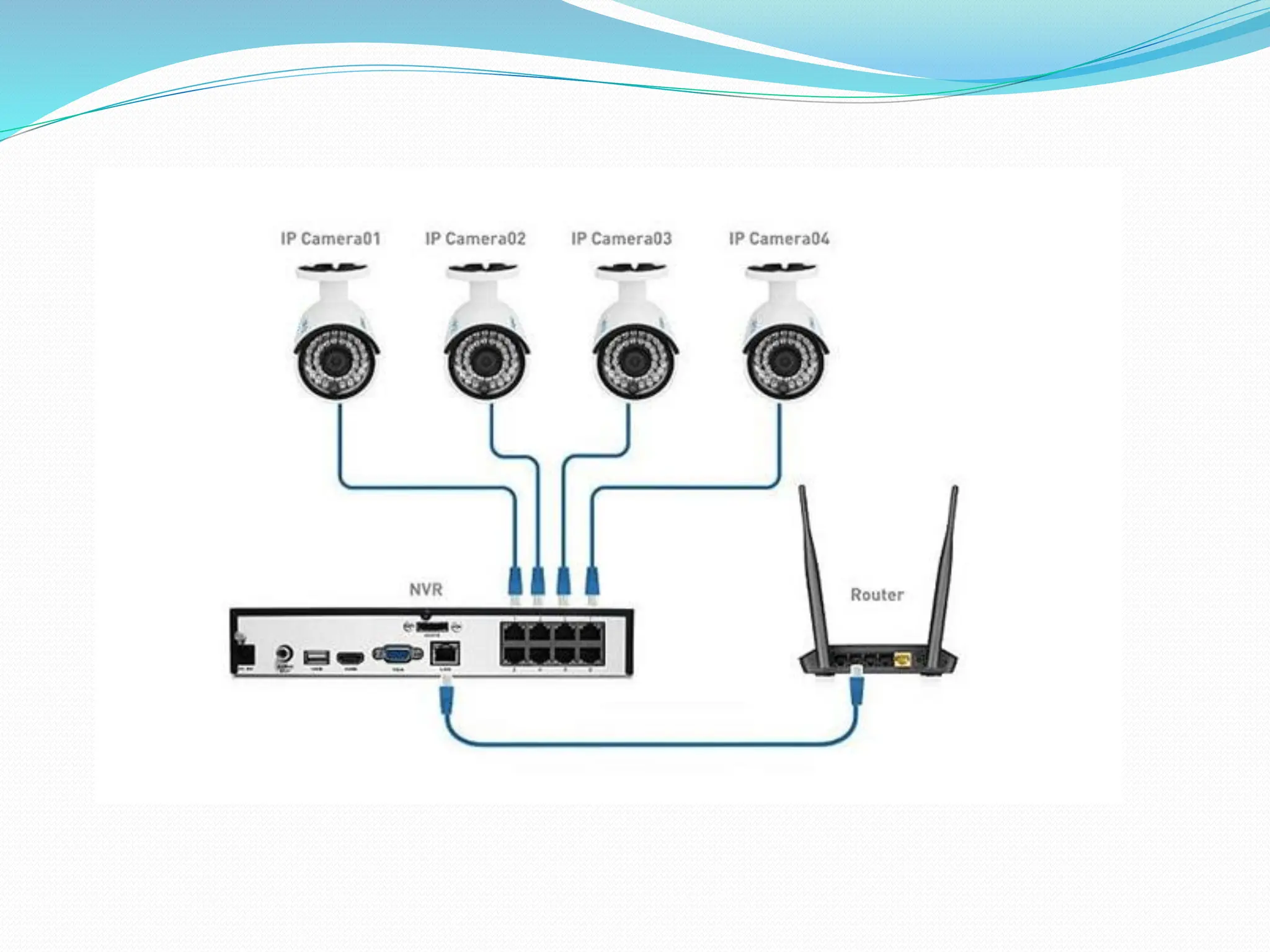
PoE security camera connection diagram:
DVR NetworkConfiguration
When connecting to the cable/DSL modem there are
several things that we determine prior to connecting
the DVR to the network. This information should
have been provided to the customer by the
telecommunications company that is providing the
internet connection.
The following listing show what information is
required to continue the installation based on the
configuration of the customers network.
When the customer is using a cable modem and
DHCP, connecting the DVR or the router directly to
the Cable Modem with some minor configuration
changes to either device is all that will be required.
64.
When theCustomer is using PPPoE and a DSL
Modem, the following information will be
required
Dynamic PPPoE
Username
Password
Static PPPoE
IP Address
Subnet Mask
Default Gateway IP
DNS Server IPs
65.
If the customerhas been setup for Static IP we need the
following information in order to proceed.
IP Address
Subnet Mask
Default Gateway IP
DNS Server IPs
66.
Please notealso that the customer needs to have the
following ports opened if the customers internal
network is protected by a firewall. Port 80, 4550, 5550,
6550, 7631 and 7632 are required to provide the remote
access to the surveillance system.
Port 80 (TCP) is used to provide the DVR specific and
proprietary HTTP server that allows direct access to the
DVR for the HTML pages. These are the pages displayed
when the customer accesses the DVR directly by IP.
Ports 4550 and 5550 are the command and data ports
that are required to provide the outgoing streaming data
for the video.
Port 6550 is the audio port required to provide the
outgoing audio stream.
67.
Two additional portsare required when the
customer needs remote access for
troubleshooting, maintenance and
operation of the DVR. Those ports at 7631 &
7632 and are designated as the PC
Anywhere access ports.
The ports must be opened and PC
Anywhere Host service must be installed
and running in the background on the DVR
for the customer to receive the Extended
Warranty services.
68.
Option 1:Cable/DSL Modem connected straight to DVR.
With only one computer utilizing the network connection
though the cable or DSL modem we can connect the DVR
directly to the modem utilizing the Ethernet cable.
DVR network access configuration
69.
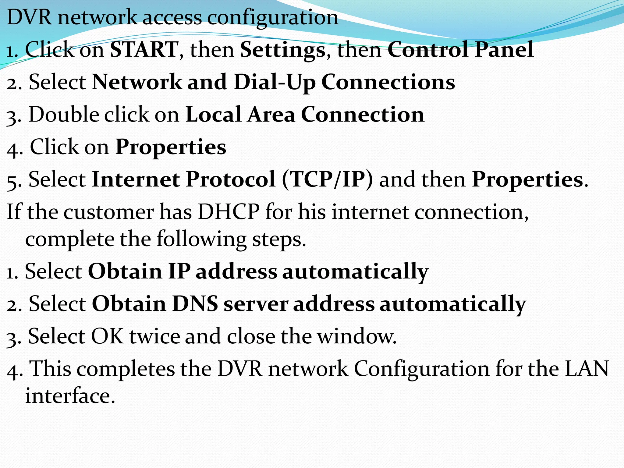
DVR network accessconfiguration
1. Click on START, then Settings, then Control Panel
2. Select Network and Dial-Up Connections
3. Double click on Local Area Connection
4. Click on Properties
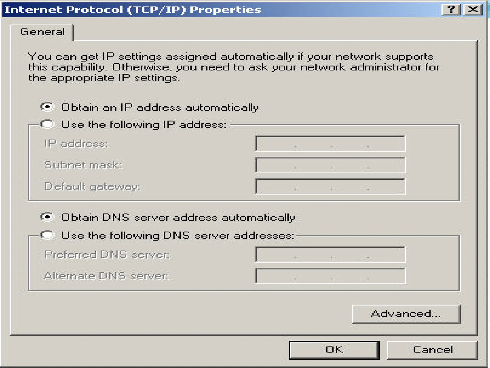
5. Select Internet Protocol (TCP/IP) and then Properties.
If the customer has DHCP for his internet connection,
complete the following steps.
1. Select Obtain IP address automatically
2. Select Obtain DNS server address automatically
3. Select OK twice and close the window.
4. This completes the DVR network Configuration for the LAN
interface.
71.
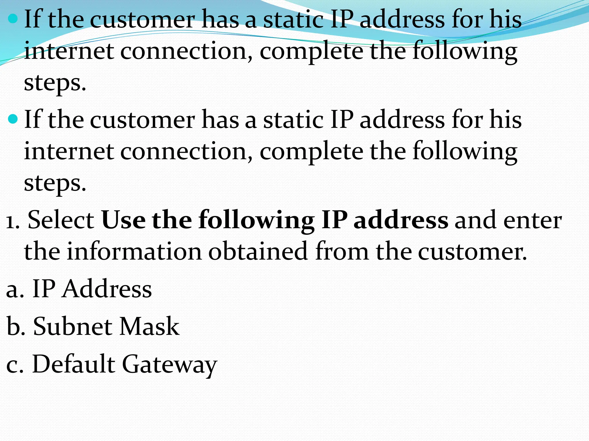
If thecustomer has a static IP address for his
internet connection, complete the following
steps.
If the customer has a static IP address for his
internet connection, complete the following
steps.
1. Select Use the following IP address and enter
the information obtained from the customer.
a. IP Address
b. Subnet Mask
c. Default Gateway
72.
2. Select Usethe following DNS server
addresses and enter the DNS server information
obtained from the customer.
3. Select OK twice and close the window.
4. This completes the DVR network Configuration
for the LAN interface.
74.
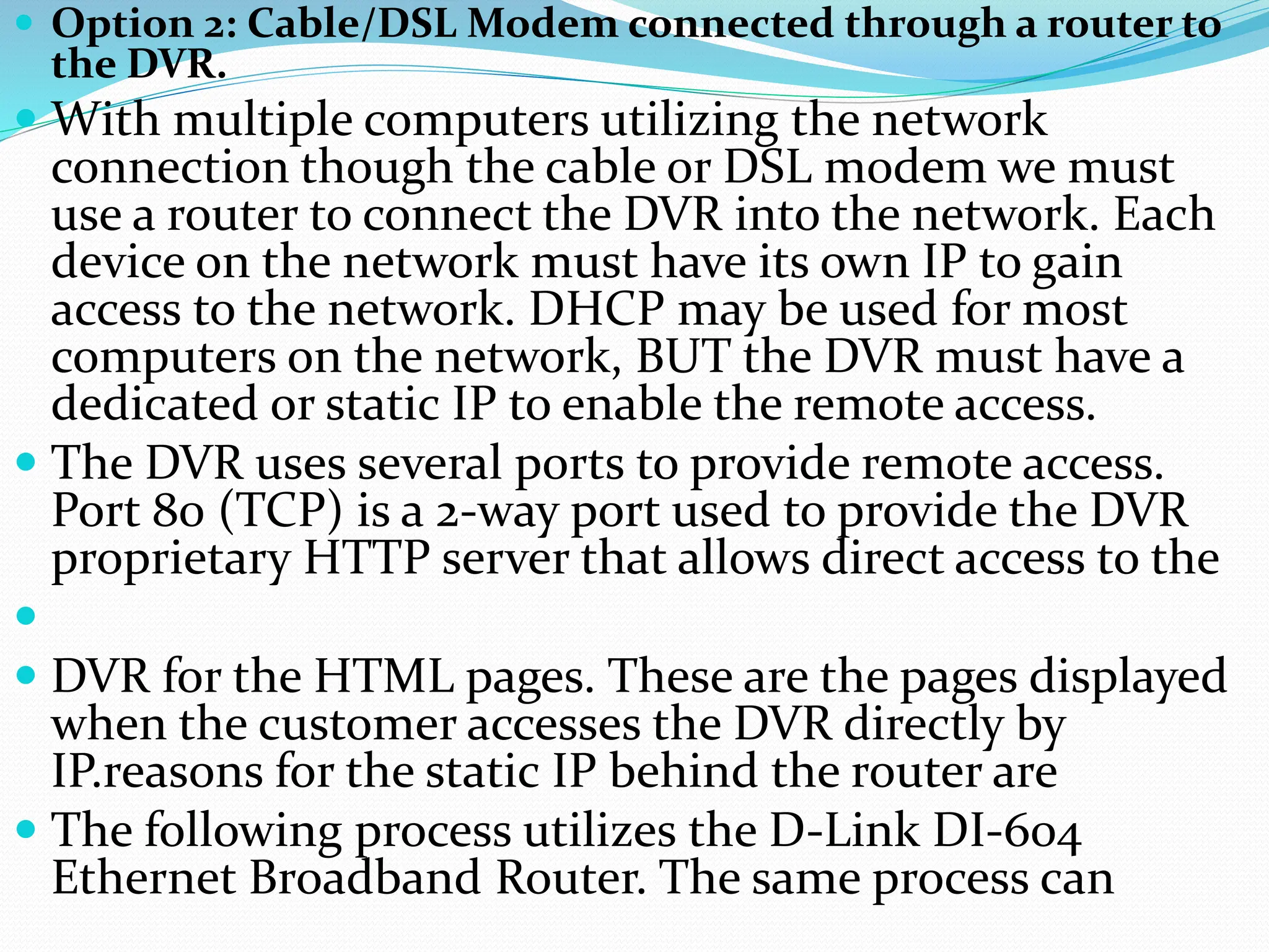
Option 2:Cable/DSL Modem connected through a router to
the DVR.
With multiple computers utilizing the network
connection though the cable or DSL modem we must
use a router to connect the DVR into the network. Each
device on the network must have its own IP to gain
access to the network. DHCP may be used for most
computers on the network, BUT the DVR must have a
dedicated or static IP to enable the remote access.
The DVR uses several ports to provide remote access.
Port 80 (TCP) is a 2-way port used to provide the DVR
proprietary HTTP server that allows direct access to the
DVR for the HTML pages. These are the pages displayed
when the customer accesses the DVR directly by
IP.reasons for the static IP behind the router are
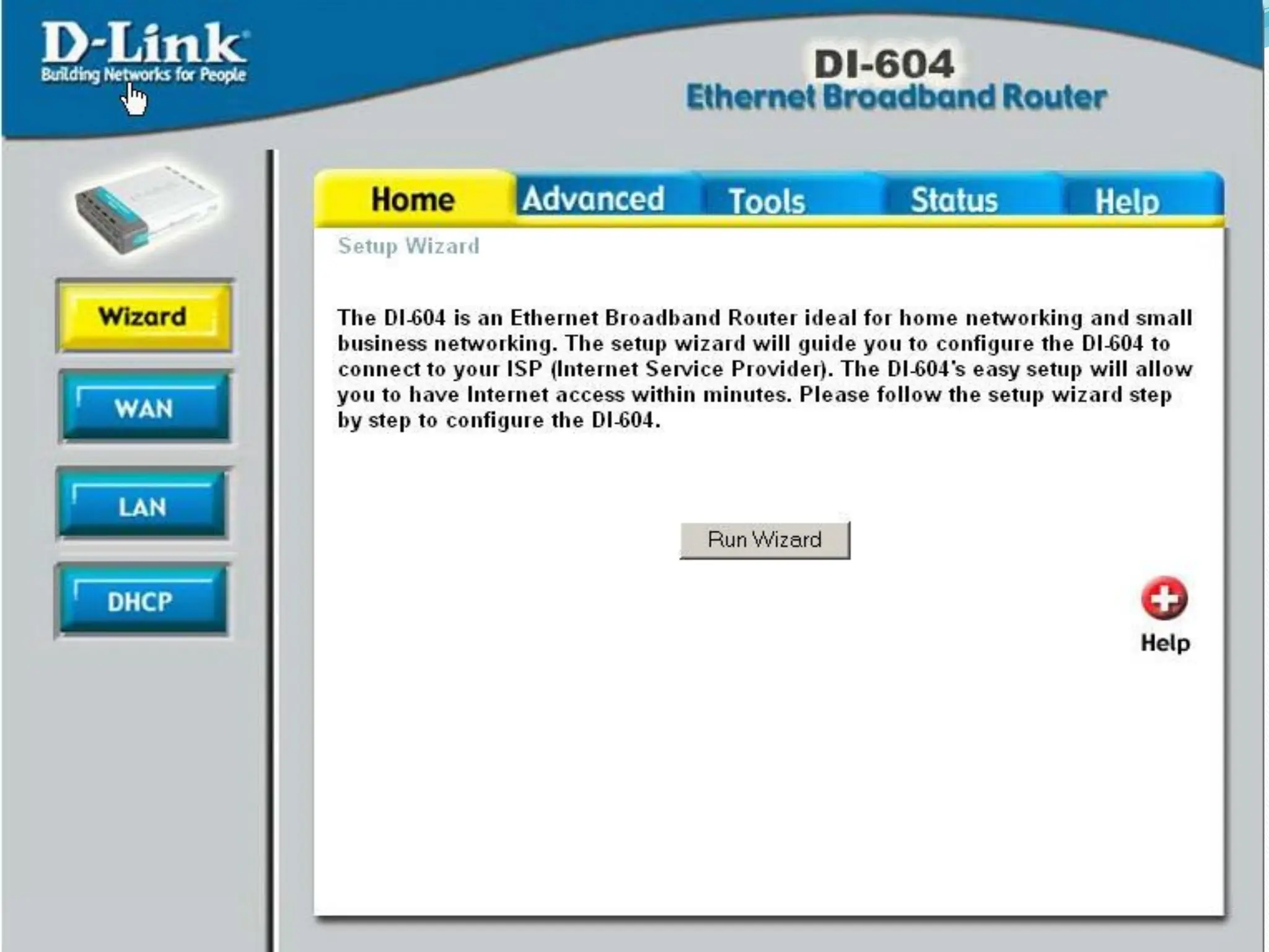
The following process utilizes the D-Link DI-604
Ethernet Broadband Router. The same process can
75.
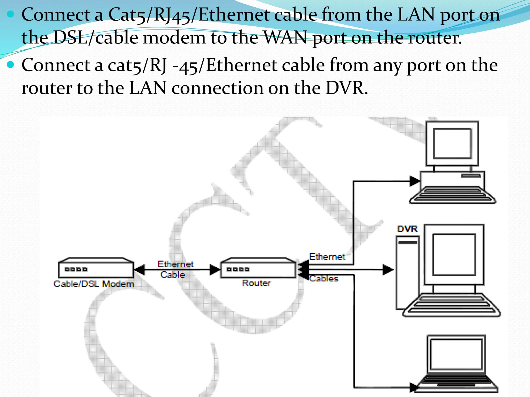
Connect aCat5/RJ45/Ethernet cable from the LAN port on
the DSL/cable modem to the WAN port on the router.
Connect a cat5/RJ -45/Ethernet cable from any port on the
router to the LAN connection on the DVR.
76.
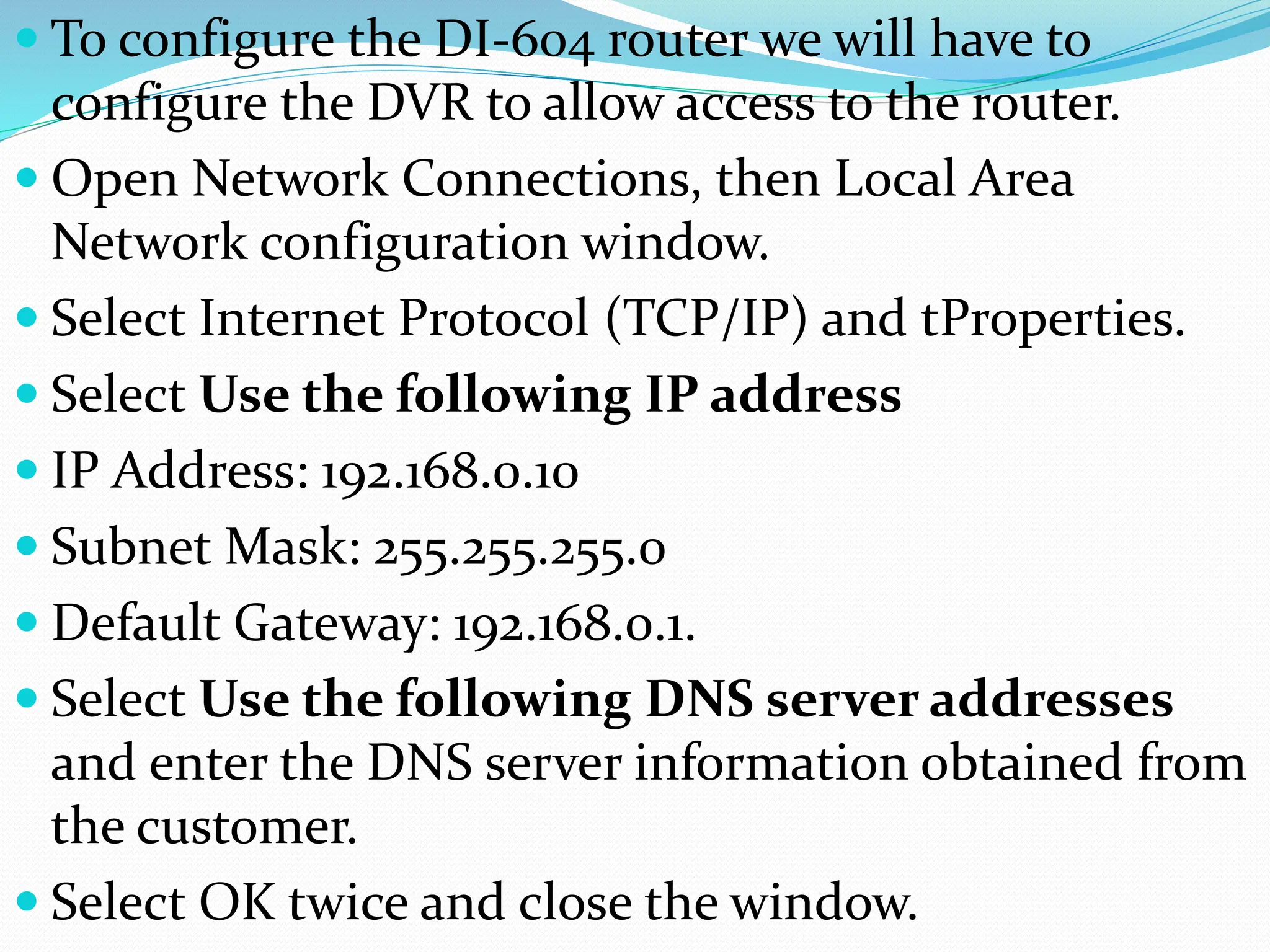
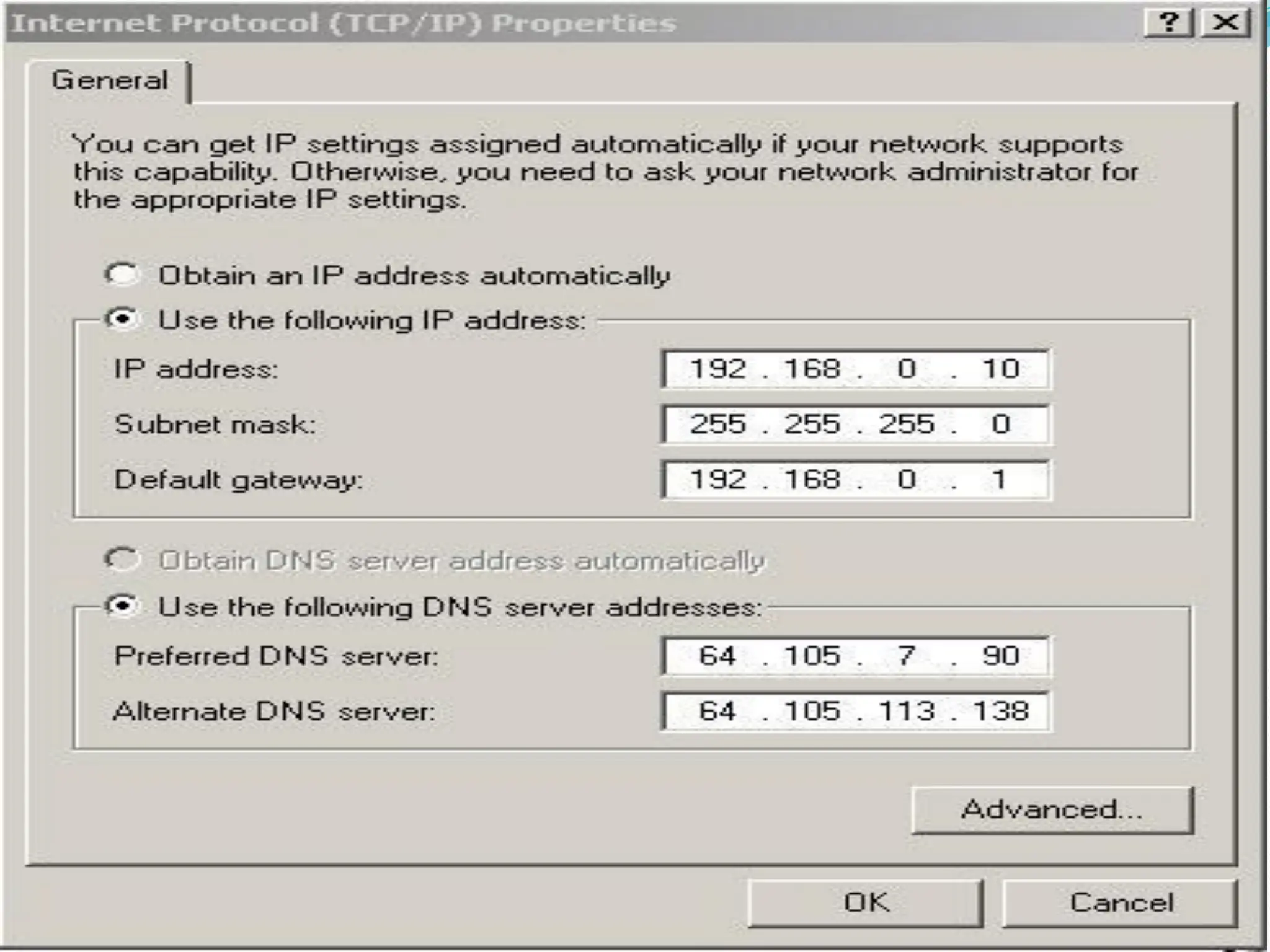
To configurethe DI-604 router we will have to
configure the DVR to allow access to the router.
Open Network Connections, then Local Area
Network configuration window.
Select Internet Protocol (TCP/IP) and tProperties.
Select Use the following IP address
IP Address: 192.168.0.10
Subnet Mask: 255.255.255.0
Default Gateway: 192.168.0.1.
Select Use the following DNS server addresses
and enter the DNS server information obtained from
the customer.
Select OK twice and close the window.
78.
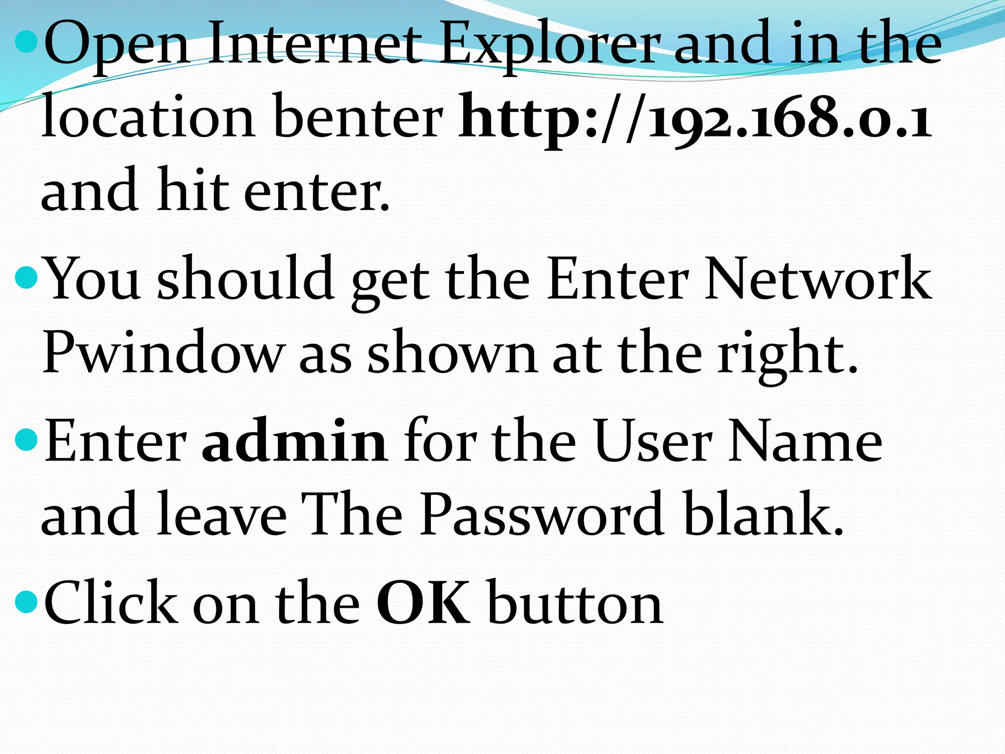
Open Internet Explorerand in the
location benter http://192.168.0.1
and hit enter.
You should get the Enter Network
Pwindow as shown at the right.
Enter admin for the User Name
and leave The Password blank.
Click on the OK button
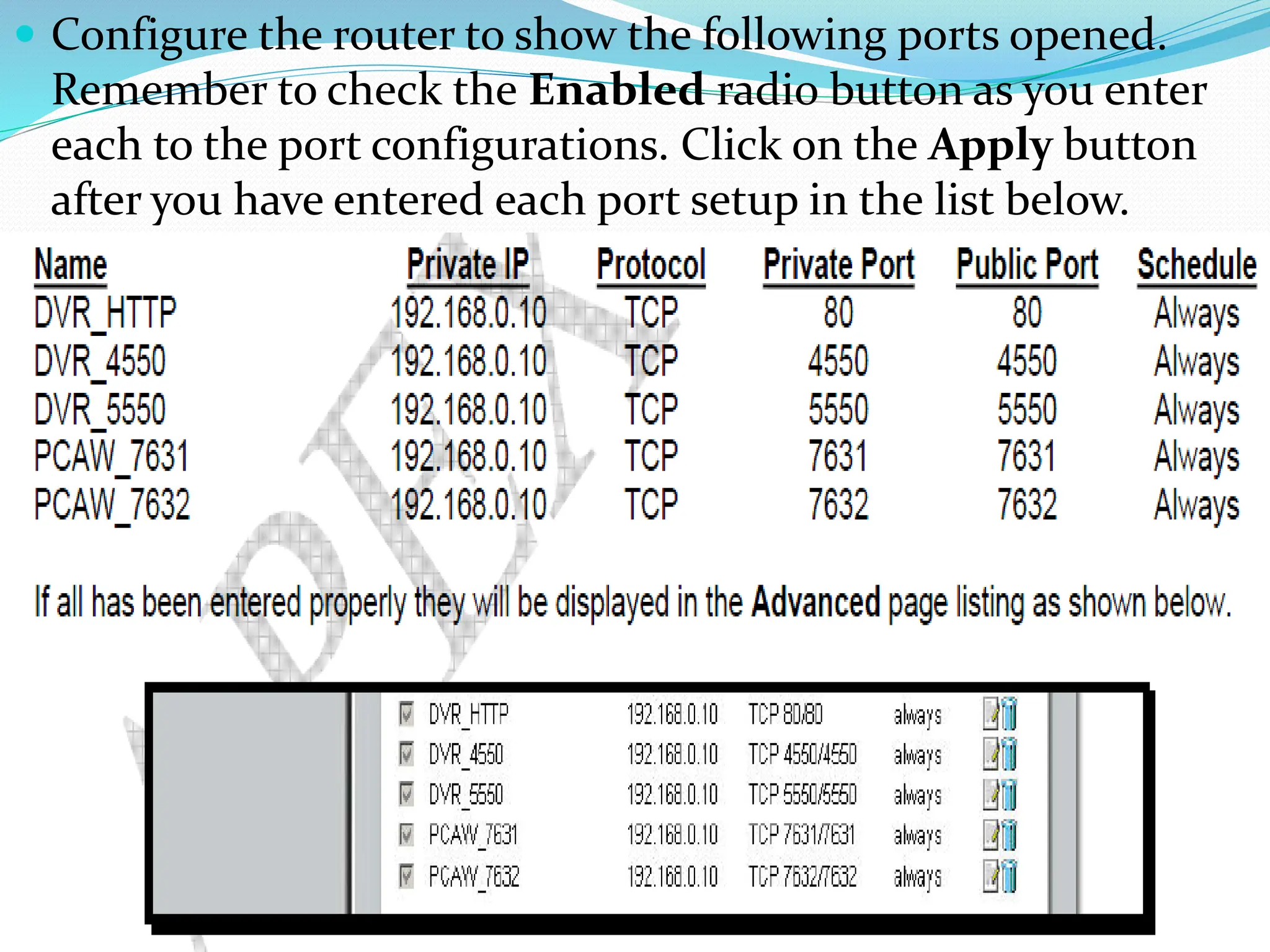
Configure therouter to show the following ports opened.
Remember to check the Enabled radio button as you enter
each to the port configurations. Click on the Apply button
after you have entered each port setup in the list below.
83.
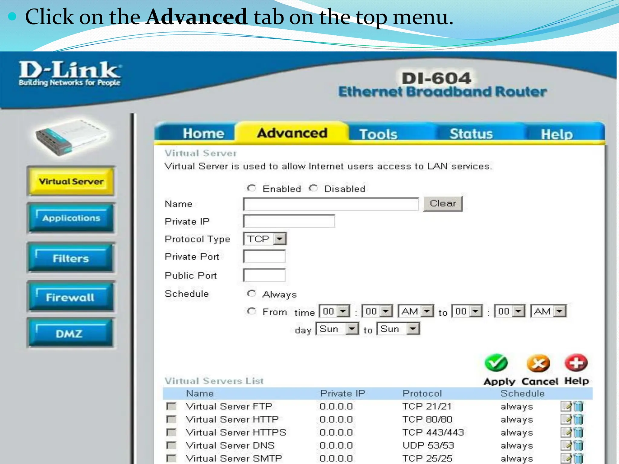
The next areathat we must
configure is the router’s access to
the network through the Cable/DSL
modem. Click on the Home tab on
the top menu, and then click on the
WAN button on the left menu. The
following page is displayed. Select
the WAN option that will apply to
the customer network.