This document provides instructions for disassembling and assembling components of a sleeve metering fuel system for a D7F track-type tractor, including:
1) Disassembling and assembling the governor, removing and installing fuel check valves and bypass valves, and removing and installing fuel injection pumps.
2) Detailed steps are provided for removing each part and reinstalling them in the proper order.
3) Precautions are outlined, such as ensuring parts are kept with their respective barrels during disassembly and reinstallation.
This document provides instructions for removing and installing a pilot control valve on a D10 track-type tractor. Key steps include removing the right side console cover, disconnecting control rods from the valve spools using pins and cotter pins, labeling and disconnecting all oil lines, and removing bolts to take off the pilot control valve. Reinstallation involves installing the pilot control valve on the bracket with bolts, connecting the labeled oil lines, and attaching the control rods to the valve spools with pins and cotter pins.
This document provides instructions for removing and installing a pilot control valve on a D10 track-type tractor. Key steps include:
1. Removing covers and disconnecting oil lines and control rods from the pilot control valve.
2. Removing bolts to detach the valve from its mounting bracket.
3. For installation, the process is reversed - the pilot control valve is mounted to the bracket with bolts, then oil lines and control rods are reconnected.
This document provides instructions for removing and installing a pilot control valve on a D10 track-type tractor. Key steps include:
1. Removing the right side console cover and disconnecting control rods and oil lines from the valve.
2. Removing bolts to take the valve off its mounting bracket.
3. Installing the valve by connecting oil lines and control rods and securing it with bolts back on the bracket.
The document provides instructions for removing and installing a pump drive on a D10 track-type tractor. It describes disconnecting various components, removing mounting bolts and hoisting out the heavy pump drive unit. Reinstallation involves cleaning parts, applying sealant, lowering into place with hoists and reconnecting components. Detailed steps are provided for disassembling and assembling the internal components of the pump drive housing. Separate instructions also cover removing, installing and overhauling a pilot control valve unit on the tractor.
This document provides instructions for disassembling and assembling components of the fuel injection system for a 245 Excavator model 95V engine, including:
- Removing and installing the fuel injection pump housing, which involves disassembling the pumps and housing components and reassembling them in the proper order.
- Removing and installing the inlet manifold, which is the part that connects the air cleaner to the cylinder head.
- Removing and installing the aftercooler, which cools the air after it passes through the turbocharger, and involves disconnecting hoses and removing housing pieces.
This document provides instructions for disassembling and assembling components of the fuel injection system for a 245 Excavator model engine. The document describes how to disassemble and assemble the fuel injection pump housing, which includes removing pumps, gears, and other internal components. It also provides instructions for removing and installing the inlet manifold and aftercooler. The steps provided are detailed and include images to illustrate the proper procedures.
Caterpillar Cat 245 EXCAVATOR (Prefix 95V) Service Repair Manual (95V00001-00...f8usjejkdmmd
This document provides instructions for disassembling and assembling components of the fuel injection system for a 245 Excavator model engine. The document describes how to disassemble and assemble the fuel injection pump housing, which includes removing pumps, gears, and other internal components. It also provides instructions for removing and installing the inlet manifold and aftercooler. The steps provided are detailed and include images to illustrate the proper procedures.
This document provides instructions for disassembling and assembling components of the fuel injection system for a 245 Excavator model engine. The document describes how to disassemble and assemble the fuel injection pump housing, which includes removing pumps, gears, and other internal components. It also provides instructions for removing and installing the inlet manifold and aftercooler. The procedures provide detailed steps for servicing these engine systems while ensuring proper identification and replacement of parts.
Caterpillar Cat 245 EXCAVATOR (Prefix 95V) Service Repair Manual (95V00001-00...fujsked9dikdkd
This document provides instructions for disassembling and assembling components of the fuel injection system for a 245 Excavator model 95V engine, including:
- Removing and installing the fuel injection pump housing, which involves disassembling the pumps and housing components and reassembling them in the proper order.
- Removing and installing the inlet manifold, which is the part that connects the air cleaner to the cylinder head.
- Removing and installing the aftercooler, which cools the air after it passes through the turbocharger, and involves disconnecting hoses and removing housing pieces.
Caterpillar Cat 245 EXCAVATOR (Prefix 95V) Service Repair Manual (95V00001-00...ufjskekdjdmw2
This document provides instructions for servicing components of a 245 Excavator engine, including:
- Disassembling and reassembling the fuel injection pump housing, which involves removing pumps, gears, and bearings, and reinstalling them in the proper order and position.
- Removing and installing the inlet manifold, which connects to the cylinder head and air cleaner components.
- Removing the aftercooler unit, which cools engine air after turbocharging, by disconnecting hoses and removing housing covers, elbows, and the core component.
Caterpillar Cat 245 EXCAVATOR (Prefix 95V) Service Repair Manual (95V00001-00...gen78guozun
This document provides instructions for servicing components of a 245 Excavator's 3406 vehicular engine, including:
- Disassembling and reassembling the fuel injection pump housing, which involves removing various parts like pumps, racks, lifters, and bearings, and replacing them in the proper order.
- Removing and installing the inlet manifold, which connects to the cylinder head and air cleaner components.
- Removing the aftercooler unit, which involves disconnecting hoses and pipes, removing mounting bolts, and taking out the core component. Detailed steps are provided for each disassembly and reassembly process.
Caterpillar Cat 245 EXCAVATOR (Prefix 95V) Service Repair Manual (95V00001-00...fjskemmd4r
This document provides instructions for disassembling and assembling components of the fuel injection system for a 245 Excavator model 95V engine, including:
- Removing and installing the fuel injection pump housing, which involves disassembling the pumps and housing components and reassembling them in the proper order.
- Removing and installing the inlet manifold, which is the part that connects the air cleaner to the cylinder head.
- Removing and installing the aftercooler, which cools the air after it passes through the turbocharger, and involves disconnecting hoses and removing housing pieces.
Caterpillar Cat 245 EXCAVATOR (Prefix 95V) Service Repair Manual (95V00001-00...jfkksemmdmd
This document provides instructions for disassembling and assembling components of the fuel injection system for a 245 Excavator model 95V engine, including:
- Removing and installing the fuel injection pump housing, which involves disassembling the pumps and housing components and reassembling them in the proper order.
- Removing and installing the inlet manifold, which is the part that connects the air cleaner to the cylinder head.
- Removing and installing the aftercooler, which cools the air after it passes through the turbocharger, and involves disconnecting hoses and removing housing pieces.
This document provides instructions for disassembling and assembling components of the fuel injection system for a 245 Excavator model 95V engine, including:
- Removing and installing the fuel injection pump housing, which involves disassembling the pumps and housing components and reassembling them in the proper order.
- Removing and installing the inlet manifold, which is the part that connects the air intake to the cylinder head.
- Removing and installing the aftercooler, which cools the air after it passes through the turbocharger, and involves disconnecting hoses and removing housing pieces.
This document provides instructions for disassembling and assembling components of the fuel injection system for a 3406 vehicular engine used in 245 excavators. The document describes how to disassemble and assemble the fuel injection pump housing by removing pumps, gears, and other internal components. It also provides instructions for removing and installing the inlet manifold, aftercooler, and related components. The purpose is to provide technicians with step-by-step guidance for servicing and repairing parts of the fuel system.
This document provides instructions for disassembling and assembling components of the fuel injection system for a 3406 vehicular engine used in 245 excavators. The document describes how to disassemble and assemble the fuel injection pump housing by removing pumps, gears, and other internal components. It also provides instructions for removing and installing the inlet manifold, aftercooler, and related components. The purpose is to repair or replace parts while maintaining proper installation and alignment of components.
This document provides instructions for disassembling and assembling components of a 245 Excavator's 3406 vehicular engine, including:
- Removing and installing the fuel injection pump housing, which involves disassembling the pumps and housing components and reassembling them in reverse order.
- Removing the inlet manifold by disconnecting air and fuel lines and removing mounting bolts, and installing it by reversing the removal steps.
- Removing the aftercooler by disconnecting hoses and pipes, removing mounting bolts, and extracting components like the core, housing pieces, and elbows.
The document provides instructions for removing and installing fuel injection lines, the fuel transfer pump, and the fuel ratio control on a Caterpillar 973 track loader. The key steps are:
1. Disconnect fuel lines and remove nuts to remove the lines and fuel transfer pump.
2. Remove bolts and the fuel ratio control unit from the governor housing.
3. Clean screens and inspect O-rings before reinstalling components.
The document provides instructions for removing and installing fuel injection lines, the fuel transfer pump, and the fuel ratio control on a Caterpillar 973 track loader. The key steps are:
1. Disconnect the fuel lines and remove the bolts holding the components.
2. Clean all parts and replace any worn seals or gaskets before installation.
3. Reinstall the components and tighten all bolts to the specified torque. Prime the fuel system after installing the fuel lines.
1) The document provides instructions for removing and installing fuel injection lines and the fuel transfer pump on a Caterpillar 973 track loader.
2) It also provides instructions for disassembling and assembling the fuel transfer pump and fuel ratio control.
3) Key steps include removing fuel lines while preventing fuel nozzles from turning, installing new O-rings, and priming the fuel system after installing new parts.
The document provides instructions for removing and installing fuel injection lines, the fuel transfer pump, and the fuel ratio control on a Caterpillar 973 track loader. The key steps are:
1. Disconnect the fuel lines and remove the bolts holding the components.
2. Clean all parts and replace any worn seals or gaskets before installation.
3. Reinstall the components and tighten all bolts to the specified torque. Prime the fuel system after installing the fuel lines.
This document provides instructions for removing and installing various components of a D7F track-type tractor engine. The components include the timing gear cover, camshaft, flywheel, crankshaft rear seal, power take-off drive gears and bearings, and removing the entire engine. Detailed steps are provided for each component, including preparatory steps, individual installation and removal steps, and concluding steps.
This document provides instructions for removing and installing various components of a D7F track-type tractor engine. It includes steps for the timing gear cover, camshaft, flywheel, crankshaft rear seal, power take-off drive gears and bearings, and removing the entire engine. The document provides detailed preparatory steps and numbered instructions for each component.
Massey Ferguson MF 384 S TRACTOR (- 300993) Parts Catalogue Manual Instant Do...onyvzcwadtu05
This document contains parts listings and technical specifications for the engine of a Massey Ferguson 384 S tractor. It includes 6 pages detailing over 60 individual parts for the engine, including the cylinder block, crankshaft, pistons, cylinder head, rocker shaft, and air induction and exhaust systems. Each part is listed with its part number, quantity, description, and any relevant comments.
Massey Ferguson MF 384 F TRACTOR, - 0894 Parts Catalogue Manual Instant Downl...onyvzcwadtu05
The document is a parts catalog for a Massey Ferguson MF 384 F tractor engine. It lists over 60 individual parts for the engine, including the cylinder block, crankshaft, pistons, connecting rods, cylinder head, rocker shaft and other components. Each part is given a reference number, part number, quantity and description, along with any replacement or additional part information.
More Related Content
Similar to Caterpillar Cat D7F TRACK-TYPE TRACTOR (Prefix 93N) Service Repair Manual Instant Download.pdf
Caterpillar Cat 245 EXCAVATOR (Prefix 95V) Service Repair Manual (95V00001-00...f8usjejkdmmd
This document provides instructions for disassembling and assembling components of the fuel injection system for a 245 Excavator model engine. The document describes how to disassemble and assemble the fuel injection pump housing, which includes removing pumps, gears, and other internal components. It also provides instructions for removing and installing the inlet manifold and aftercooler. The steps provided are detailed and include images to illustrate the proper procedures.
This document provides instructions for disassembling and assembling components of the fuel injection system for a 245 Excavator model engine. The document describes how to disassemble and assemble the fuel injection pump housing, which includes removing pumps, gears, and other internal components. It also provides instructions for removing and installing the inlet manifold and aftercooler. The procedures provide detailed steps for servicing these engine systems while ensuring proper identification and replacement of parts.
Caterpillar Cat 245 EXCAVATOR (Prefix 95V) Service Repair Manual (95V00001-00...fujsked9dikdkd
This document provides instructions for disassembling and assembling components of the fuel injection system for a 245 Excavator model 95V engine, including:
- Removing and installing the fuel injection pump housing, which involves disassembling the pumps and housing components and reassembling them in the proper order.
- Removing and installing the inlet manifold, which is the part that connects the air cleaner to the cylinder head.
- Removing and installing the aftercooler, which cools the air after it passes through the turbocharger, and involves disconnecting hoses and removing housing pieces.
Caterpillar Cat 245 EXCAVATOR (Prefix 95V) Service Repair Manual (95V00001-00...ufjskekdjdmw2
This document provides instructions for servicing components of a 245 Excavator engine, including:
- Disassembling and reassembling the fuel injection pump housing, which involves removing pumps, gears, and bearings, and reinstalling them in the proper order and position.
- Removing and installing the inlet manifold, which connects to the cylinder head and air cleaner components.
- Removing the aftercooler unit, which cools engine air after turbocharging, by disconnecting hoses and removing housing covers, elbows, and the core component.
Caterpillar Cat 245 EXCAVATOR (Prefix 95V) Service Repair Manual (95V00001-00...gen78guozun
This document provides instructions for servicing components of a 245 Excavator's 3406 vehicular engine, including:
- Disassembling and reassembling the fuel injection pump housing, which involves removing various parts like pumps, racks, lifters, and bearings, and replacing them in the proper order.
- Removing and installing the inlet manifold, which connects to the cylinder head and air cleaner components.
- Removing the aftercooler unit, which involves disconnecting hoses and pipes, removing mounting bolts, and taking out the core component. Detailed steps are provided for each disassembly and reassembly process.
Caterpillar Cat 245 EXCAVATOR (Prefix 95V) Service Repair Manual (95V00001-00...fjskemmd4r
This document provides instructions for disassembling and assembling components of the fuel injection system for a 245 Excavator model 95V engine, including:
- Removing and installing the fuel injection pump housing, which involves disassembling the pumps and housing components and reassembling them in the proper order.
- Removing and installing the inlet manifold, which is the part that connects the air cleaner to the cylinder head.
- Removing and installing the aftercooler, which cools the air after it passes through the turbocharger, and involves disconnecting hoses and removing housing pieces.
Caterpillar Cat 245 EXCAVATOR (Prefix 95V) Service Repair Manual (95V00001-00...jfkksemmdmd
This document provides instructions for disassembling and assembling components of the fuel injection system for a 245 Excavator model 95V engine, including:
- Removing and installing the fuel injection pump housing, which involves disassembling the pumps and housing components and reassembling them in the proper order.
- Removing and installing the inlet manifold, which is the part that connects the air cleaner to the cylinder head.
- Removing and installing the aftercooler, which cools the air after it passes through the turbocharger, and involves disconnecting hoses and removing housing pieces.
This document provides instructions for disassembling and assembling components of the fuel injection system for a 245 Excavator model 95V engine, including:
- Removing and installing the fuel injection pump housing, which involves disassembling the pumps and housing components and reassembling them in the proper order.
- Removing and installing the inlet manifold, which is the part that connects the air intake to the cylinder head.
- Removing and installing the aftercooler, which cools the air after it passes through the turbocharger, and involves disconnecting hoses and removing housing pieces.
This document provides instructions for disassembling and assembling components of the fuel injection system for a 3406 vehicular engine used in 245 excavators. The document describes how to disassemble and assemble the fuel injection pump housing by removing pumps, gears, and other internal components. It also provides instructions for removing and installing the inlet manifold, aftercooler, and related components. The purpose is to provide technicians with step-by-step guidance for servicing and repairing parts of the fuel system.
This document provides instructions for disassembling and assembling components of the fuel injection system for a 3406 vehicular engine used in 245 excavators. The document describes how to disassemble and assemble the fuel injection pump housing by removing pumps, gears, and other internal components. It also provides instructions for removing and installing the inlet manifold, aftercooler, and related components. The purpose is to repair or replace parts while maintaining proper installation and alignment of components.
This document provides instructions for disassembling and assembling components of a 245 Excavator's 3406 vehicular engine, including:
- Removing and installing the fuel injection pump housing, which involves disassembling the pumps and housing components and reassembling them in reverse order.
- Removing the inlet manifold by disconnecting air and fuel lines and removing mounting bolts, and installing it by reversing the removal steps.
- Removing the aftercooler by disconnecting hoses and pipes, removing mounting bolts, and extracting components like the core, housing pieces, and elbows.
This document provides instructions for disassembling and assembling components of a 245 Excavator's 3406 vehicular engine, including:
- Removing and installing the fuel injection pump housing, which involves disassembling the pumps and housing components and reassembling them in reverse order.
- Removing the inlet manifold by disconnecting air and fuel lines and removing mounting bolts, and installing it by reversing the removal steps.
- Removing the aftercooler by disconnecting hoses and pipes, removing mounting bolts, and extracting components like the core, housing pieces, and elbows.
The document provides instructions for removing and installing fuel injection lines, the fuel transfer pump, and the fuel ratio control on a Caterpillar 973 track loader. The key steps are:
1. Disconnect fuel lines and remove nuts to remove the lines and fuel transfer pump.
2. Remove bolts and the fuel ratio control unit from the governor housing.
3. Clean screens and inspect O-rings before reinstalling components.
The document provides instructions for removing and installing fuel injection lines, the fuel transfer pump, and the fuel ratio control on a Caterpillar 973 track loader. The key steps are:
1. Disconnect the fuel lines and remove the bolts holding the components.
2. Clean all parts and replace any worn seals or gaskets before installation.
3. Reinstall the components and tighten all bolts to the specified torque. Prime the fuel system after installing the fuel lines.
1) The document provides instructions for removing and installing fuel injection lines and the fuel transfer pump on a Caterpillar 973 track loader.
2) It also provides instructions for disassembling and assembling the fuel transfer pump and fuel ratio control.
3) Key steps include removing fuel lines while preventing fuel nozzles from turning, installing new O-rings, and priming the fuel system after installing new parts.
The document provides instructions for removing and installing fuel injection lines, the fuel transfer pump, and the fuel ratio control on a Caterpillar 973 track loader. The key steps are:
1. Disconnect the fuel lines and remove the bolts holding the components.
2. Clean all parts and replace any worn seals or gaskets before installation.
3. Reinstall the components and tighten all bolts to the specified torque. Prime the fuel system after installing the fuel lines.
The document provides instructions for removing and installing fuel injection lines, the fuel transfer pump, and the fuel ratio control on a Caterpillar 973 track loader. The key steps are:
1. Disconnect the fuel lines and remove the bolts holding the components.
2. Clean all parts and replace any worn seals or gaskets before installation.
3. Reinstall the components and tighten all bolts to the specified torque. Prime the fuel system after installing the fuel lines.
This document provides instructions for removing and installing various components of a D7F track-type tractor engine. The components include the timing gear cover, camshaft, flywheel, crankshaft rear seal, power take-off drive gears and bearings, and removing the entire engine. Detailed steps are provided for each component, including preparatory steps, individual installation and removal steps, and concluding steps.
This document provides instructions for removing and installing various components of a D7F track-type tractor engine. It includes steps for the timing gear cover, camshaft, flywheel, crankshaft rear seal, power take-off drive gears and bearings, and removing the entire engine. The document provides detailed preparatory steps and numbered instructions for each component.
Similar to Caterpillar Cat D7F TRACK-TYPE TRACTOR (Prefix 93N) Service Repair Manual Instant Download.pdf (20)
Massey Ferguson MF 384 S TRACTOR (- 300993) Parts Catalogue Manual Instant Do...onyvzcwadtu05
This document contains parts listings and technical specifications for the engine of a Massey Ferguson 384 S tractor. It includes 6 pages detailing over 60 individual parts for the engine, including the cylinder block, crankshaft, pistons, cylinder head, rocker shaft, and air induction and exhaust systems. Each part is listed with its part number, quantity, description, and any relevant comments.
Massey Ferguson MF 384 F TRACTOR, - 0894 Parts Catalogue Manual Instant Downl...onyvzcwadtu05
The document is a parts catalog for a Massey Ferguson MF 384 F tractor engine. It lists over 60 individual parts for the engine, including the cylinder block, crankshaft, pistons, connecting rods, cylinder head, rocker shaft and other components. Each part is given a reference number, part number, quantity and description, along with any replacement or additional part information.
The document suggests that if clicking the above button is invalid, the user should first download the document and then click the link to download the complete manual. It thanks the reader for their time.
This document provides instructions for disassembling and assembling the main hydraulic pump on a M315D Wheeled Excavator. It lists 34 steps for disassembly, removing components like pistons, springs, seals and housing pieces. It then lists 36 steps for assembly, installing components in reverse order and noting proper orientation of marked parts. Precautions are provided regarding contained fluids, released spring forces, and keeping parts clean from contaminants. Required specialty tools are also listed.
This document provides instructions for assembling the main hydraulic pump on an excavator model. It lists the required tools and parts. It then provides 49 steps with accompanying illustrations, describing how to install each component of the pump in detail, including bearings, seals, pistons, springs, and valves. The final step instructs the technician to install the assembled pump.
The document provides instructions for installing a swing drive on an excavator model M315D. It lists the required tools and parts. The procedure involves 28 steps, including installing bearings, seals, gears, and other components into the swing drive housing. Specific torque specifications and dimensional checks are listed to ensure proper assembly. Installation is completed by positioning the swing drive in the swing brake housing and securing it with bolts.
This document provides instructions for disassembling and assembling the final drive of a D9R track-type tractor. It describes removing components such as the planetary carrier, gears, shafts, and hub. Various tools are required, including link brackets, a push-puller tool group, driver group, and hydraulic cylinder assembly. Precautions are given for using hydraulic cylinders and puller studs during disassembly. The multi-step process includes pressing, lifting, and removing components from the planetary carrier, sun gear, and hub.
This document provides instructions to disassemble and assemble the final drive of a D9R track-type tractor. It describes:
1) Removing over 30 components of the final drive including gears, shafts, bearings, seals and hubs using various tools.
2) Inspecting all parts and replacing any that are damaged.
3) Heating some bearings cones to aid removal and ensuring proper temperatures when installing.
4) Precisely assembling the components in reverse order, taking care with sealing surfaces.
1) The document provides instructions for removing and installing the final drive planetary carrier in a D9R track-type tractor.
2) It describes using various tools to remove the carrier, hub components, seals, and gears. It then explains how to clean and prepare the parts for installation and use the tools to reinstall the components in reverse order.
3) Fourteen steps are outlined to remove the carrier and twelve steps are provided to install it back into the final drive assembly.
The document provides instructions for disassembling and assembling the steering clutch and brake of a Caterpillar D7R track-type tractor. It details 20 steps to disassemble the components which include removing bolts, plates, bearings, seals and other parts. The 20 steps to assemble are also outlined and include cleaning parts, applying oil, heating bearings, and reinstalling components in reverse order. Special safety precautions are noted regarding spring loaded components.
The document provides assembly instructions for installing a final drive on a D7R track-type tractor. It describes 31 steps to assemble bearings, seals, gears, shafts, covers and other components. Tools required include drivers, seal installers, brackets and spacers. Precise torques and clearances are specified. The assembly is completed by filling the final drive with oil and reconnecting the track.
Caterpillar Cat D7R II WATER FORDING TRACTOR (Prefix DJT) Service Repair Manu...onyvzcwadtu05
This document provides instructions for disassembling and assembling the steering planetary and brake of a D7R Series II Water Fording Tractor. It describes removing 24 components including the planetary group, brake, ring gear, friction discs, piston, and springs. Reassembly involves installing these components in reverse order, noting proper orientation and torque specifications. Tools required include link brackets, a driver group, forcing bolts, and sealant.
Caterpillar Cat D7R II TRACK-TYPE TRACTOR (Prefix AGN) Service Repair Manual ...onyvzcwadtu05
The document provides instructions for removing a final drive, steering planetary, and brake assembly from a D7R II track-type tractor. It describes using lifting brackets, shackles, bolts and nuts to attach a hoist to the assembly and remove it from the tractor. The assembly weighs approximately 800 kg (1750 lb) and precautions are listed to provide means to stop the machine without the brake installed. Fluids must be contained while working on components to collect any fluids that may drain out.
This document provides instructions for disassembling and assembling the final drives on a D7H track-type tractor. The main steps for disassembly are to remove the final drives from the machine, then disassemble the internal components which include removing planet carriers, gears, shafts, and bearings. For assembly, the components are installed in reverse order, with specifics on cleaning, heating/cooling parts, and using installation tools to properly set clearances and ensure metal-to-metal contact between parts.
This document provides instructions for servicing the final drives on a D7H track-type tractor. It describes how to remove and disassemble the final drives, including removing the planet carriers, gears, shafts and other components. It then describes how to assemble the final drives, including installing bearings, seals, rings and other parts back into the hubs and carriers. The goal is to provide maintenance technicians with step-by-step directions for servicing these critical components.
1) The document provides instructions for removing and installing pistons, connecting rods, connecting rod bearings, and crankshaft main bearings for a Caterpillar 3306 engine.
2) The procedure involves using tools to compress piston rings, installing pistons and connecting rods onto the crankshaft, checking clearances of connecting rod bearings, and removing/installing main bearing caps.
3) Technicians are advised to keep all parts clean and lubricated with engine oil to prevent damage and wear.
The document provides instructions for removing and installing sprocket assemblies on a track-type tractor. It involves 22 steps to remove the assemblies, which includes draining oil, removing seals, bearings, and other components. The 23 steps to install include pressing in new seals, bearings, and sprockets using specialized tools and applying precise forces, and adjusting bearings after reinstalling track roller frames. Proper cleaning, lubrication and torque specifications are noted throughout.
The document provides step-by-step instructions for removing and installing sprocket assemblies on a final drive case. It involves draining oil, removing the sprocket and various components using specialized tools, cleaning surfaces, replacing seals, installing new components in reverse order, and filling with oil. Proper alignment and torque specifications are noted throughout.
The document provides instructions for removing and installing final drive case assemblies on a D7G track-type tractor. It describes draining oil from the final drive case and removing components like caps, locks, nuts, seals and bearings. It explains using tools and hoists to separate the sprocket, holder assembly and adjusting nut as a unit from the tapered sprocket shaft. Finally, it outlines reinstalling the sprocket assembly and adjusting the bearings.
The document provides instructions for removing and installing various components of a D7F track-type tractor engine, including the crankshaft rear seal, power take-off drive gears and bearings, the entire engine assembly, the flywheel housing, camshaft bearings, and more. The steps are described in detail and include preparatory steps, numbered instructions, and concluding steps for each component.
Expanding Access to Affordable At-Home EV Charging by Vanessa WarheitForth
Vanessa Warheit, Co-Founder of EV Charging for All, gave this presentation at the Forth Addressing The Challenges of Charging at Multi-Family Housing webinar on June 11, 2024.
Understanding Catalytic Converter Theft:
What is a Catalytic Converter?: Learn about the function of catalytic converters in vehicles and why they are targeted by thieves.
Why are They Stolen?: Discover the valuable metals inside catalytic converters (such as platinum, palladium, and rhodium) that make them attractive to criminals.
Steps to Prevent Catalytic Converter Theft:
Parking Strategies: Tips on where and how to park your vehicle to reduce the risk of theft, such as parking in well-lit areas or secure garages.
Protective Devices: Overview of various anti-theft devices available, including catalytic converter locks, shields, and alarms.
Etching and Marking: The benefits of etching your vehicle’s VIN on the catalytic converter or using a catalytic converter marking kit to make it traceable and less appealing to thieves.
Surveillance and Monitoring: Recommendations for using security cameras and motion-sensor lights to deter thieves.
Statistics and Insights:
Theft Rates by Borough: Analysis of data to determine which borough in NYC experiences the highest rate of catalytic converter thefts.
Recent Trends: Current trends and patterns in catalytic converter thefts to help you stay aware of emerging hotspots and tactics used by thieves.
Benefits of This Presentation:
Awareness: Increase your awareness about catalytic converter theft and its impact on vehicle owners.
Practical Tips: Gain actionable insights and tips to effectively prevent catalytic converter theft.
Local Insights: Understand the specific risks in different NYC boroughs, helping you take targeted preventive measures.
This presentation aims to equip you with the knowledge and tools needed to protect your vehicle from catalytic converter theft, ensuring you are prepared and proactive in safeguarding your property.
Implementing ELDs or Electronic Logging Devices is slowly but surely becoming the norm in fleet management. Why? Well, integrating ELDs and associated connected vehicle solutions like fleet tracking devices lets businesses and their in-house fleet managers reap several benefits. Check out the post below to learn more.
Welcome to ASP Cranes, your trusted partner for crane solutions in Raipur, Chhattisgarh! With years of experience and a commitment to excellence, we offer a comprehensive range of crane services tailored to meet your lifting and material handling needs.
At ASP Cranes, we understand the importance of reliable and efficient crane operations in various industries, from construction and manufacturing to logistics and infrastructure development. That's why we strive to deliver top-notch solutions that enhance productivity, safety, and cost-effectiveness for our clients.
Our services include:
Crane Rental: Whether you need a crawler crane for heavy lifting or a hydraulic crane for versatile operations, we have a diverse fleet of well-maintained cranes available for rent. Our rental options are flexible and can be customized to suit your project requirements.
Crane Sales: Looking to invest in a crane for your business? We offer a wide selection of new and used cranes from leading manufacturers, ensuring you find the perfect equipment to match your needs and budget.
Crane Maintenance and Repair: To ensure optimal performance and safety, regular maintenance and timely repairs are essential for cranes. Our team of skilled technicians provides comprehensive maintenance and repair services to keep your equipment running smoothly and minimize downtime.
Crane Operator Training: Proper training is crucial for safe and efficient crane operation. We offer specialized training programs conducted by certified instructors to equip operators with the skills and knowledge they need to handle cranes effectively.
Custom Solutions: We understand that every project is unique, which is why we offer custom crane solutions tailored to your specific requirements. Whether you need modifications, attachments, or specialized equipment, we can design and implement solutions that meet your needs.
At ASP Cranes, customer satisfaction is our top priority. We are dedicated to delivering reliable, cost-effective, and innovative crane solutions that exceed expectations. Contact us today to learn more about our services and how we can support your project in Raipur, Chhattisgarh, and beyond. Let ASP Cranes be your trusted partner for all your crane needs!
What Could Be Behind Your Mercedes Sprinter's Power Loss on Uphill RoadsSprinter Gurus
Unlock the secrets behind your Mercedes Sprinter's uphill power loss with our comprehensive presentation. From fuel filter blockages to turbocharger troubles, we uncover the culprits and empower you to reclaim your vehicle's peak performance. Conquer every ascent with confidence and ensure a thrilling journey every time.
Ever been troubled by the blinking sign and didn’t know what to do?
Here’s a handy guide to dashboard symbols so that you’ll never be confused again!
Save them for later and save the trouble!
EV Charging at MFH Properties by Whitaker JamiesonForth
Whitaker Jamieson, Senior Specialist at Forth, gave this presentation at the Forth Addressing The Challenges of Charging at Multi-Family Housing webinar on June 11, 2024.
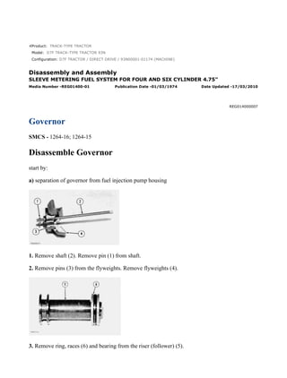
1. Product: TRACK-TYPE TRACTOR
Model: D7F TRACK-TYPE TRACTOR 93N
Configuration: D7F TRACTOR / DIRECT DRIVE / 93N00001-01174 (MACHINE)
Disassembly and Assembly
SLEEVE METERING FUEL SYSTEM FOR FOUR AND SIX CYLINDER 4.75"
Media Number -REG01400-01 Publication Date -01/03/1974 Date Updated -17/03/2010
REG014000007
Governor
SMCS - 1264-16; 1264-15
Disassemble Governor
start by:
a) separation of governor from fuel injection pump housing
1. Remove shaft (2). Remove pin (1) from shaft.
2. Remove pins (3) from the flyweights. Remove flyweights (4).
3. Remove ring, races (6) and bearing from the riser (follower) (5).
1/6
D7F TRACTOR / DIRECT DRIVE / 93N00001-01174 (MACHINE)(UEG0169S - 00)...
2021/8/20
https://127.0.0.1/sisweb/sisweb/techdoc/techdoc_print_page.jsp?returnurl=/sis...
2. 4. Remove cover (7) and spring (8) from governor housing.
NOTE: There is force on the cover from the spring.
5. Remove seal (9) from cover.
6. Remove cover (10) for the low and high idle adjustment.
7. Remove locknut and screw (13) for the high idle adjustment.
8. Remove bolt (15) and washers for the low idle adjustment.
9. Remove spring (16) and guide.
10. Remove pin (14) and plate (11).
11. Remove shaft (12) from the housing.
12. Remove pin (18) and two spacers (17) from shaft.
NOTE: Earlier fuel systems have a ball in place of spacers (17) and pin (18).
2/6
D7F TRACTOR / DIRECT DRIVE / 93N00001-01174 (MACHINE)(UEG0169S - 00)...
2021/8/20
https://127.0.0.1/sisweb/sisweb/techdoc/techdoc_print_page.jsp?returnurl=/sis...
3. 13. Remove shaft (19) from the governor housing.
14. Remove washer (20) and levers (21) and (22) from governor housing.
15. Remove cover (23) from governor housing.
16. Remove seal (25) and bearing.
17. Remove seals (24) and (26) from governor housing.
Assemble Governor
3/6
D7F TRACTOR / DIRECT DRIVE / 93N00001-01174 (MACHINE)(UEG0169S - 00)...
2021/8/20
https://127.0.0.1/sisweb/sisweb/techdoc/techdoc_print_page.jsp?returnurl=/sis...
4. 1. Install bearing and seal in the housing with tool (A). The lip of the seal must be toward the
bearing.
2. Install seal (1) in housing with tool (A). The lip of seal must be toward inside of housing.
3. Install seal (2) in housing with tooling (B). The lip of seal must be toward the inside of housing.
4. Install shaft (3) in the housing.
5. Install plates (4), spacers (8) and pin (7) on shaft.
6. Install shaft (5) in housing and through washer (9) and levers (6).
7. Install pin (11) in holes of the plates.
8. Install screw (10) and locknut for high idle adjustment.
4/6
D7F TRACTOR / DIRECT DRIVE / 93N00001-01174 (MACHINE)(UEG0169S - 00)...
2021/8/20
https://127.0.0.1/sisweb/sisweb/techdoc/techdoc_print_page.jsp?returnurl=/sis...
5. 9. Install spring (13) and guide.
10. Install bolts (12) and washer for low idle adjustment.
11. Push plate and pin (11) over toward the bolt (12) and tighten the bolt.
12. Install seal in cover with tooling (B). The lip of seal must be toward the inside.
13. Install spring (15) in the cover. Install cover (14) on housing.
NOTICE
The spring (15) must be installed with the end of spring as shown.
14. Install cover (16) for the idle adjustment screws.
5/6
D7F TRACTOR / DIRECT DRIVE / 93N00001-01174 (MACHINE)(UEG0169S - 00)...
2021/8/20
https://127.0.0.1/sisweb/sisweb/techdoc/techdoc_print_page.jsp?returnurl=/sis...
6. 15. Install bearing (19) between the races (18) on riser (follower) (17). Install ring (20) that holds
the washers on the riser (follower).
16. Install pin in shaft (23).
17. Install flyweights (22) and pin (21).
18. Install shaft (23) in the flyweight assembly.
end by:
a) connection of governor to fuel injection pump housing
6/6
D7F TRACTOR / DIRECT DRIVE / 93N00001-01174 (MACHINE)(UEG0169S - 00)...
2021/8/20
https://127.0.0.1/sisweb/sisweb/techdoc/techdoc_print_page.jsp?returnurl=/sis...
7. Product: TRACK-TYPE TRACTOR
Model: D7F TRACK-TYPE TRACTOR 93N
Configuration: D7F TRACTOR / DIRECT DRIVE / 93N00001-01174 (MACHINE)
Disassembly and Assembly
SLEEVE METERING FUEL SYSTEM FOR FOUR AND SIX CYLINDER 4.75"
Media Number -REG01400-01 Publication Date -01/03/1974 Date Updated -17/03/2010
REG014000008
Fuel Check Valve And Bypass Valve
SMCS - 1264-16; 1264-15
Remove Fuel Check Valve And Bypass Valve
1. Remove fuel from the pump housing and install on tool (A).
2. Remove cover (2) from top cover.
3. Remove fuel inlet and return housing (1) from top cover.
1/4
D7F TRACTOR / DIRECT DRIVE / 93N00001-01174 (MACHINE)(UEG0169S - 00)...
2021/8/20
https://127.0.0.1/sisweb/sisweb/techdoc/techdoc_print_page.jsp?returnurl=/sis...
8. 4. Remove elbow (3) and disc (4) from fuel inlet and return housing.
NOTE: The function of the disc (4) is to keep the fuel in the pump housing from returning to the
tank when the engine is not in operation. If the fuel tank is higher than the fuel pump housing, disc
and housing is not needed.
5. Remove cover (5) and fuel channel from pump housing.
6. Remove spring and bypass valve (6) from housing.
7. Remove check valve (7).
8. Remove fuel channel (8) and check valve from cover.
9. Remove check valve (9) and spring from fuel channel.
NOTE: Earlier fuel systems have two check valves (7) and (9). Check valve (9) is not needed.
Remove check valve (9) and fill the hole in fuel channel with weld or replace channel.
Install Fuel Check Valve And Bypass Valve
1. Install fuel channel (1) on cover (2).
2/4
D7F TRACTOR / DIRECT DRIVE / 93N00001-01174 (MACHINE)(UEG0169S - 00)...
2021/8/20
https://127.0.0.1/sisweb/sisweb/techdoc/techdoc_print_page.jsp?returnurl=/sis...
9. 2. Install spring and bypass valve (4) in housing with the rounded end up.
3. Install check valve (3) evenly in pump housing.
NOTE: Do not install a check valve that is bent.
4. Install cover on pump housing. Be sure the bypass valve spring is in the groove in the cover.
5. Install disc (5) and elbow on fuel inlet and return housing.
6. Install fuel inlet and return housing (6) on cover (8).
7. Install cover (7) on cover (8).
8. Remove fuel injection pump housing and governor from tool (A).
3/4
D7F TRACTOR / DIRECT DRIVE / 93N00001-01174 (MACHINE)(UEG0169S - 00)...
2021/8/20
https://127.0.0.1/sisweb/sisweb/techdoc/techdoc_print_page.jsp?returnurl=/sis...
10. Product: TRACK-TYPE TRACTOR
Model: D7F TRACK-TYPE TRACTOR 93N
Configuration: D7F TRACTOR / DIRECT DRIVE / 93N00001-01174 (MACHINE)
Disassembly and Assembly
SLEEVE METERING FUEL SYSTEM FOR FOUR AND SIX CYLINDER 4.75"
Media Number -REG01400-01 Publication Date -01/03/1974 Date Updated -17/03/2010
REG014000009
Fuel Injection Pumps
SMCS - 1251-12; 1251-15; 1251-16; 1251-11
Fuel Injection Pump And Housing
1/6
D7F TRACTOR / DIRECT DRIVE / 93N00001-01174 (MACHINE)(UEG0169S - 00)...
2021/8/20
https://127.0.0.1/sisweb/sisweb/techdoc/techdoc_print_page.jsp?returnurl=/sis...
12. Remove Fuel Injection Pumps
NOTICE
Before any service work is to be done on the fuel system the outer
surface of injection pump housing must be clean.
1. Remove the cover assembly (1) from the pump housing. Remove spring for the bypass valve.
3/6
D7F TRACTOR / DIRECT DRIVE / 93N00001-01174 (MACHINE)(UEG0169S - 00)...
2021/8/20
https://127.0.0.1/sisweb/sisweb/techdoc/techdoc_print_page.jsp?returnurl=/sis...
13. 2. Loosen the bushing (2) from the pump housing with tool (A).
NOTE: Do not loosen the screws (3) that hold levers to shaft when removing or installing pumps.
If levers are moved, fuel pump adjustment will be changed.
3. Remove the fuel injection pump from the pump housing. The sleeve on the plunger will slide
off the lever as the pump is removed.
Install Fuel Injection Pumps
1. Put the fuel injection pump (1) in the bore of pump housing.
2. The sleeve (2) will be engaged with lever when installed correctly.
NOTICE
If levers have been moved on the shaft, fuel pump adjustment must be
made. (See TESTING AND ADJUSTING).
3. Tighten the bushing with wrench (A) to a torque of 70 ± 5 lb.ft. (9.7 ± 0.7 mkg).
4/6
D7F TRACTOR / DIRECT DRIVE / 93N00001-01174 (MACHINE)(UEG0169S - 00)...
2021/8/20
https://127.0.0.1/sisweb/sisweb/techdoc/techdoc_print_page.jsp?returnurl=/sis...
14. 4. Put the spring on the bypass valve. Install the cover assembly on the pump housing. Be sure the
spring (4) is in position in the cover.
Disassemble Fuel Injection Pumps
start by:
a) remove fuel injection pumps
1. Remove the bushing (1) from the bonnet (2).
2. Remove the ring (3) from the bonnet and barrel (7). Remove the check valve (6) and spring (4)
from the bonnet.
3. Remove the spring (8) and washer (5). Remove the plunger (9) and sleeve (10).
NOTE: Keep the plunger and sleeve with their respective barrel for installation. Do not use
plungers, sleeves, and barrels with other plungers, sleeves, and barrels.
Assemble Fuel Injection Pumps
5/6
D7F TRACTOR / DIRECT DRIVE / 93N00001-01174 (MACHINE)(UEG0169S - 00)...
2021/8/20
https://127.0.0.1/sisweb/sisweb/techdoc/techdoc_print_page.jsp?returnurl=/sis...
15. 1. Install the sleeve (4), plunger (5), spring (2), and washer (3) on the barrel (1).
NOTE: Be sure sleeve and plunger are installed in original barrel, and large hole in plunger is up.
2. Install check valve and spring in bonnet. Connect the barrel and bonnet and install the ring.
Install the bushing on the bonnet.
end by:
a) install fuel injection pumps
6/6
D7F TRACTOR / DIRECT DRIVE / 93N00001-01174 (MACHINE)(UEG0169S - 00)...
2021/8/20
https://127.0.0.1/sisweb/sisweb/techdoc/techdoc_print_page.jsp?returnurl=/sis...
16. Product: TRACK-TYPE TRACTOR
Model: D7F TRACK-TYPE TRACTOR 93N
Configuration: D7F TRACTOR / DIRECT DRIVE / 93N00001-01174 (MACHINE)
Disassembly and Assembly
SLEEVE METERING FUEL SYSTEM FOR FOUR AND SIX CYLINDER 4.75"
Media Number -REG01400-01 Publication Date -01/03/1974 Date Updated -17/03/2010
REG014000010
Fuel Transfer Pump
SMCS - 1156-11; 1256-12
Remove Fuel Transfer Pump
1/7
D7F TRACTOR / DIRECT DRIVE / 93N00001-01174 (MACHINE)(UEG0169S - 00)...
2021/8/20
https://127.0.0.1/sisweb/sisweb/techdoc/techdoc_print_page.jsp?returnurl=/sis...
18. 1. Install the fuel injection pump housing on tool (A).
2. Install timing pin (1) to keep the injection pump camshaft from turning during disassembly and
assembly.
3. Install bolt (B) in the threads of sleeve (3). Tighten the bolt until sleeve can be removed.
NOTICE
Do not hit on bolt or sleeve. This will cause damage to the unit.
4. Remove bolts (4) that hold body to the housing.
5. Remove body (2) from the housing.
6. Remove idler gear (6) from body.
7. Remove O-ring seal (5) and the two lip-type seals from body.
3/7
D7F TRACTOR / DIRECT DRIVE / 93N00001-01174 (MACHINE)(UEG0169S - 00)...
2021/8/20
https://127.0.0.1/sisweb/sisweb/techdoc/techdoc_print_page.jsp?returnurl=/sis...
19. 8. Remove drive gear (8) from shaft.
9. Remove key (7) from the shaft.
Install Fuel Transfer Pump
1. Install the inner seal in the body with tooling (A). The lip of seal must be toward the pump
gears.
2. Install the outer seal in the body with tooling (B). The lip of seal must be toward the outside.
NOTICE
Always be careful not to scratch or cause damage to the machined
surface of the pump body.
4/7
D7F TRACTOR / DIRECT DRIVE / 93N00001-01174 (MACHINE)(UEG0169S - 00)...
2021/8/20
https://127.0.0.1/sisweb/sisweb/techdoc/techdoc_print_page.jsp?returnurl=/sis...
20. 3. Install the O-ring seal (2) and idler gear (1) on the body.
4. Install the key and drive gear (3) on the shaft.
5. Install the body (4) on the housing.
6. Install the bolts that hold the body to the housing.
NOTE: The pump body for the truck engine fuel system has an oil passage through the pump
body. Other pump bodies do not have the oil passage.
7. Put sleeve (5) in position on camshaft.
5/7
D7F TRACTOR / DIRECT DRIVE / 93N00001-01174 (MACHINE)(UEG0169S - 00)...
2021/8/20
https://127.0.0.1/sisweb/sisweb/techdoc/techdoc_print_page.jsp?returnurl=/sis...
21. NOTE: The timing pin (6) must be in position as shown to keep the camshaft from turning during
assembly.
8. Install sleeve on camshaft with tooling (C).
NOTICE
Do not hit the sleeve with a hammer to install it. This will put end force
on the camshaft and cause damage to the other components in the
pump housing.
6/7
D7F TRACTOR / DIRECT DRIVE / 93N00001-01174 (MACHINE)(UEG0169S - 00)...
2021/8/20
https://127.0.0.1/sisweb/sisweb/techdoc/techdoc_print_page.jsp?returnurl=/sis...
22. 9. The end clearance of the camshaft must be 0.58 ± 0.46 mm (.023 ± .018 in.) after sleeve (5) is
installed.
end by:
a) install fuel injection pump housing and governor
7/7
D7F TRACTOR / DIRECT DRIVE / 93N00001-01174 (MACHINE)(UEG0169S - 00)...
2021/8/20
https://127.0.0.1/sisweb/sisweb/techdoc/techdoc_print_page.jsp?returnurl=/sis...
23. Model: D7F TRACK-TYPE TRACTOR 93N
Configuration: D7F TRACTOR / DIRECT DRIVE / 93N00001-01174 (MACHINE)
Disassembly and Assembly
SLEEVE METERING FUEL SYSTEM FOR FOUR AND SIX CYLINDER 4.75"
Media Number -REG01400-01 Publication Date -01/03/1974 Date Updated -17/03/2010
REG014000011
Fuel Injection Pump Housing
SMCS - 1253-15; 1253-16
Disassemble Fuel Injection Pump Housing
start by:
a) remove fuel injection pumps
b) separation of governor from fuel injection pump housing
c) remove fuel transfer pump
1. Remove dowel from housing for torque spring lever.
1/3
D7F TRACTOR / DIRECT DRIVE / 93N00001-01174 (MACHINE)(UEG0169S - 00)...
2021/8/20
https://127.0.0.1/sisweb/sisweb/techdoc/techdoc_print_page.jsp?returnurl=/sis...
24. 2. Loosen screws that hold levers (1) to the sleeve control shaft (2).
3. Remove the sleeve control shaft (2) from housing.
4. Remove lifters and roller assemblies (3) from the housing.
NOTE: Make identification of lifters and rollers for identification in their respective bore in
housing.
5. Remove camshaft from housing.
Assemble Fuel Injection Pump Housing
2/3
D7F TRACTOR / DIRECT DRIVE / 93N00001-01174 (MACHINE)(UEG0169S - 00)...
2021/8/20
https://127.0.0.1/sisweb/sisweb/techdoc/techdoc_print_page.jsp?returnurl=/sis...
25. 1. Install camshaft (1) in housing.
2. Install lifters and roller assemblies (5) in their respective bores in housing.
NOTE: Install the lifters with grooves of lifters in alignment with pins (6) in housing.
3. Put the sleeve control shaft (3) in housing. Slide levers (2) on shaft. Push the shaft into position
in housing.
4. Install dowel (4) in housing.
end by:
a) make adjustment to the sleeve control shaft (See TESTING AND ADJUSTING FOR
CORRECT PROCEDURE)
b) install fuel transfer pump
c) install fuel injection pumps
d) connection of governor to fuel injection pump housing
3/3
D7F TRACTOR / DIRECT DRIVE / 93N00001-01174 (MACHINE)(UEG0169S - 00)...
2021/8/20
https://127.0.0.1/sisweb/sisweb/techdoc/techdoc_print_page.jsp?returnurl=/sis...
26. Suggest:
If the above button click is invalid.
Please download this document
first, and then click the above link
to download the complete manual.
Thank you so much for reading
27. Product: TRACK-TYPE TRACTOR
Model: D7F TRACK-TYPE TRACTOR 93N
Configuration: D7F TRACTOR / DIRECT DRIVE / 93N00001-01174 (MACHINE)
Disassembly and Assembly
D7F ENGINE
Media Number -REG00822-00 Publication Date -01/11/1971 Date Updated -17/03/2010
REG008220001
Transmission & Engine Oil Coolers
SMCS - 1366-12; 1366-11; 1378-11
Remove Transmission Oil Cooler
1. Drain the engine cooling system - capacity 12 U.S. Gal. (45 liters).
2. Disconnect oil inlet line (1) and oil outlet line (2) from the oil cooler.
3. Remove the oil cooler-to-elbow assembly mounting bolts (3).
4. Remove the oil cooler-to-support bracket mounting bolt (4). Remove the transmission oil cooler
- weight 25 lbs. (11 kg).
Install Transmission Oil Cooler
1/2
D7F TRACTOR / DIRECT DRIVE / 93N00001-01174 (MACHINE)(UEG0169S - 00)...
2021/8/20
https://127.0.0.1/sisweb/sisweb/techdoc/techdoc_print_page.jsp?returnurl=/sis...
28. 1. Position the transmission oil cooler (1) on engine, and install the oil cooler-to-support bracket
mounting bolt.
2. Install the oil cooler-to-elbow assembly mounting bolts.
3. Connect the oil inlet line and oil outlet line to the oil cooler.
4. Fill the engine cooling system.
Remove Engine Oil Cooler
1. Drain the engine cooling system - capacity 12 U.S. Gal. (45 liters).
2. Loosen the water inlet bonnet hose clamps (5), and slide the hose (1) back on bonnet (2).
3. Remove oil filter case (7) and element.
4. Remove the oil level gauge guide clamp mounting bolt (3).
5. Remove the oil cooler-to-elbow assembly mounting bolts (4).
6. Remove the two support bracket mounting bolts (6). Remove the engine oil cooler and oil filter
base as a unit.
7. Separate the oil filter base from oil cooler.
2/2
D7F TRACTOR / DIRECT DRIVE / 93N00001-01174 (MACHINE)(UEG0169S - 00)...
2021/8/20
https://127.0.0.1/sisweb/sisweb/techdoc/techdoc_print_page.jsp?returnurl=/sis...