SlideShare a Scribd company logo
Shutdown SIS
Previous Screen
Product: TRACK-TYPE TRACTOR
Model: D10 TRACK-TYPE TRACTOR 76X
Configuration: D10 TRACTOR / POWER SHIFT / 76X00359-UP (MACHINE) POWERED BY D348 ENGINE
Disassembly and Assembly
D10 Tractor Vehicle Systems
Media Number -SENR7671-01 Publication Date -01/06/1982 Date Updated -12/10/2001
Pump Drive
SMCS - 3108-11; 3108-12; 3108-15; 3108-16
Remove Pump Drive
START BY:
a) remove rear bottom guard *
b) remove air conditioner compressor
c) remove alternator
d) remove fan drive pump
e) remove implement pump
f) remove drive shaft for pump drive
g) remove transmission torque converter and steering clutch scavenge pump *
h) remove transmission and torque converter charging pump *
*
Operation location is in POWER TRAIN DISASSEMBLY AND ASSEMBLY section.
1/13
D10 TRACTOR / POWER SHIFT / 76X00359-UP (MACHINE) POWERED BY D34...
2021/11/24
https://127.0.0.1/sisweb/sisweb/techdoc/techdoc_print_page.jsp?returnurl=/sis...
1. Remove bracket (1) from the pump drive.
2. Remove vee belts (2).
3. Remove five bolts (3) and drive shaft guard bracket (4).
4. Disconnect oil lines (5) and (6) from the pump drive.
5. Install tooling (A) on the top inside of the cab. Install nylon strap (7) to pump drive (8) and
tooling (A).
2/13
D10 TRACTOR / POWER SHIFT / 76X00359-UP (MACHINE) POWERED BY D34...
2021/11/24
https://127.0.0.1/sisweb/sisweb/techdoc/techdoc_print_page.jsp?returnurl=/sis...
6. Disconnect oil line (9) from the pump drive.
7. Remove bolts (10) that hold the bottom mounting assembly to the frame.
8. Remove two bolts (11) that hold the top mounting assembly to the frame.
9. Use tooling (A) and remove pump drive (8) from the machine. The weight is 245 lb. (111 kg).
Install Pump Drive
1. Use tooling (A) and a nylon strap and put pump drive (1) in position against the frame.
2. Install two bolts (2) that hold the top mounting assembly to the frame.
3/13
D10 TRACTOR / POWER SHIFT / 76X00359-UP (MACHINE) POWERED BY D34...
2021/11/24
https://127.0.0.1/sisweb/sisweb/techdoc/techdoc_print_page.jsp?returnurl=/sis...
3. Install bolts (4) that hold the bottom mounting assembly to the frame.
4. Connect oil line (3) to the pump drive.
5. Remove tooling (A) and nylon strap (5).
6. Connect oil lines (6) and (7) to the pump drive.
7. Install drive shaft guard bracket (8).
4/13
D10 TRACTOR / POWER SHIFT / 76X00359-UP (MACHINE) POWERED BY D34...
2021/11/24
https://127.0.0.1/sisweb/sisweb/techdoc/techdoc_print_page.jsp?returnurl=/sis...
8. Put vee belts (9) in position on the pulleys.
9. Install bracket (10) on the pump drive.
END BY:
a) install transmission and torque converter charging pump *
b) install transmission, torque converter and steering clutch scavenge pump *
c) install drive shaft for pump drive
d) install implement pump
e) install fan drive pump
f) install alternator
g) install air conditioning compressor
h) install rear bottom guard *
*
Operation location is in POWER TRAIN DISASSEMBLY AND ASSEMBLY section.
Disassemble Pump Drive
5/13
D10 TRACTOR / POWER SHIFT / 76X00359-UP (MACHINE) POWERED BY D34...
2021/11/24
https://127.0.0.1/sisweb/sisweb/techdoc/techdoc_print_page.jsp?returnurl=/sis...
START BY:
a) remove pump drive
1. Loosen nut (1) until washer (2) is approximately-1/8 in. (3.2 mm) away from yoke (3). Do not
remove the nut at this time.
6/13
D10 TRACTOR / POWER SHIFT / 76X00359-UP (MACHINE) POWERED BY D34...
2021/11/24
https://127.0.0.1/sisweb/sisweb/techdoc/techdoc_print_page.jsp?returnurl=/sis...
2. Install tooling (A) on the yoke. Use tooling (A) to loosen the yoke from the taper. Remove
tooling (A), nut (1), washer (2) and yoke (3).
3. Loosen nut (4) until washer (5) is approximately 1/8" (3.2 mm) away from pulley (6). Do not
remove nut (4) at this time.
4. Install tooling (B) as shown. Use tooling (B) to loosen the pulley from the taper. Remove
tooling (B), nut (4), washer (5) and pulley (6). Remove the key from the gear.
5. Use a hoist and turn the pump drive over. The weight is 245 lb. (111 kg).
6. Remove alternator bracket (7) from the pump drive.
7. Install tooling (C) and fasten a hoist as shown. Remove the bolts that hold the cover to the
housing. Remove cover (8). The weight is 80 lb. (36 kg).
7/13
D10 TRACTOR / POWER SHIFT / 76X00359-UP (MACHINE) POWERED BY D34...
2021/11/24
https://127.0.0.1/sisweb/sisweb/techdoc/techdoc_print_page.jsp?returnurl=/sis...
8. Remove two lip type seals (9) from cover (8).
9. Use tooling (D) and remove bearing cups (10) from cover (8).
10. Remove gears (11), (12) and (13) from housing (14).
11. Use tooling (E) and remove bearing cone (15) from each side of the gears.
8/13
D10 TRACTOR / POWER SHIFT / 76X00359-UP (MACHINE) POWERED BY D34...
2021/11/24
https://127.0.0.1/sisweb/sisweb/techdoc/techdoc_print_page.jsp?returnurl=/sis...
12. Remove two lip type seals (16) from housing (14).
13. Use tooling (D) and remove three bearing cups (17) from housing (14).
14. Remove mount assemblies (18) from the housing if a replacement is needed.
9/13
D10 TRACTOR / POWER SHIFT / 76X00359-UP (MACHINE) POWERED BY D34...
2021/11/24
https://127.0.0.1/sisweb/sisweb/techdoc/techdoc_print_page.jsp?returnurl=/sis...
Assemble Pump Drive
1. Clean and inspect all parts. Make a replacement of the parts if needed. Put clean oil on the lips
of the seals, bearing cups and cones and gears.
2. Use tooling (A) and install two lip type seals (1) in housing (2). The lips of the seals must be
toward the inside of the housing as shown. Turn the housing over.
3. Lower the temperature of bearing cups (3). Install bearing cups (3) in housing (2).
4. If mount assemblies (4) were removed, install the mount assemblies until the center line of bolt
hole is 1.14 ± .010 in. (29.0 ± 0.25 mm) below surface (X).
5. Heat bearing cones (5) to a maximum temperature of 275°F (135°C). Install bearing cones (5)
on gear (6).
10/13
D10 TRACTOR / POWER SHIFT / 76X00359-UP (MACHINE) POWERED BY D...
2021/11/24
https://127.0.0.1/sisweb/sisweb/techdoc/techdoc_print_page.jsp?returnurl=/sis...
6. Heat bearing cones (7) to a maximum temperature of 275°F (135°C). Install bearing cones (7)
on gear (8).
7. Heat bearing cones (9) to a maximum temperature of 275°F (135°C). Install bearing cones (9)
on gear (10).
8. Install gears (10), (8) and (6) in housing (2). See the illustrations for the correct way to install
the gears in the housing.
9. Lower the temperature of three bearing cups (11). Install three bearing cups (11) in the cover.
11/13
D10 TRACTOR / POWER SHIFT / 76X00359-UP (MACHINE) POWERED BY D...
2021/11/24
https://127.0.0.1/sisweb/sisweb/techdoc/techdoc_print_page.jsp?returnurl=/sis...
10. Use tooling (A) and install two lip type seals (12) in cover (13). The lips of the seals must be
toward the inside of the cover as shown. Turn the cover over.
NOTE: If the studs were removed from the housing and the cover, install them and tighten the 1/2
in. studs to a torque of 40 ± 7 lb.ft. (55 ± 10 N·m) and 5/8 in. studs to a torque of 75 ± 11 lb.ft.
(100 ± 15 N·m).
11. Install tooling (B) to the cover. Fasten a hoist to tooling (B). Put 7M7260 Liquid Gasket
Material on the surfaces of housing (2) and cover (13) that make contact with each other. Install
cover (13) on housing (2).
12. Install alternator bracket (14) on the pump drive.
13. Install the key in the gear. Make an alignment of the groove in pulley (17) with the key in the
gear. Install pulley (17), washer (16) and nut (15).
12/13
D10 TRACTOR / POWER SHIFT / 76X00359-UP (MACHINE) POWERED BY D...
2021/11/24
https://127.0.0.1/sisweb/sisweb/techdoc/techdoc_print_page.jsp?returnurl=/sis...
14. Install yoke (20), washer (19) and nut (18) on the gear.
END BY:
a) install pump drive
Copyright 1993 - 2021 Caterpillar Inc.
All Rights Reserved.
Private Network For SIS Licensees.
Wed Nov 24 12:10:32 UTC+0800 2021
13/13
D10 TRACTOR / POWER SHIFT / 76X00359-UP (MACHINE) POWERED BY D...
2021/11/24
https://127.0.0.1/sisweb/sisweb/techdoc/techdoc_print_page.jsp?returnurl=/sis...
Shutdown SIS
Previous Screen
Product: TRACK-TYPE TRACTOR
Model: D10 TRACK-TYPE TRACTOR 76X
Configuration: D10 TRACTOR / POWER SHIFT / 76X00359-UP (MACHINE) POWERED BY D348 ENGINE
Disassembly and Assembly
D10 Tractor Vehicle Systems
Media Number -SENR7671-01 Publication Date -01/06/1982 Date Updated -12/10/2001
Pilot Control Valve
SMCS - 5059-16; 5059-11; 5059-12; 5059-15
Remove Pilot Control Valve
START BY:
a) remove seat *
*
Operation location is in OPERATOR'S STATION DISASSEMBLY AND ASSEMBLY section.
Hydraulic oil that is under pressure and hot can cause bodily injury.
Move the control levers to relieve the pressure in the hydraulic system.
Slowly loosen cap to release any pressure in the hydraulic tank. Let the
hydraulic oil become cool before any lines are disconnected in the
hydraulic system.
1. Remove cover (1) from the right side console.
1/9
D10 TRACTOR / POWER SHIFT / 76X00359-UP (MACHINE) POWERED BY D34...
2021/11/24
https://127.0.0.1/sisweb/sisweb/techdoc/techdoc_print_page.jsp?returnurl=/sis...
2. Remove bolts (4) that hold the flange retainers (3) and boots (2) to the pilot control valve. Pull
boots (2) and retainers (3) up on the control rods.
3. Remove cotter pins (6) and pins (7) to disconnect control rods (5) from the valve spools of the
pilot control valve.
4. Put identification on all the oil lines connected to the pilot control valve for correct installation.
Disconnect all oil lines (10) from the pilot control valve.
5. Remove bolts (9) that hold the pilot control valve to the bracket. Remove pilot control valve (8)
from the bracket.
Install Pilot Control Valve
1. Install pilot control valve (1) on the bucket.
2/9
D10 TRACTOR / POWER SHIFT / 76X00359-UP (MACHINE) POWERED BY D34...
2021/11/24
https://127.0.0.1/sisweb/sisweb/techdoc/techdoc_print_page.jsp?returnurl=/sis...
2. Connect all oil lines (2) to the pilot control valve.
3. Move control rods (3) into position and install pins (5) and cotter pins (4) that connect the
control rods to the valve spools of the pilot control valve.
4. Move boots (6) and retainers (7) into position on the flanges. Install bolts (8) that hold the
flanges, retainers and boots to the pilot control valve.
5. Install cover (9) on the right side console.
END BY:
a) install seat *
3/9
D10 TRACTOR / POWER SHIFT / 76X00359-UP (MACHINE) POWERED BY D34...
2021/11/24
https://127.0.0.1/sisweb/sisweb/techdoc/techdoc_print_page.jsp?returnurl=/sis...
*
This operation location is in OPERATOR'S STATION DISASSEMBLY AND ASSEMBLY
section.
Disassemble Pilot Control Valve
START BY:
a) remove pilot control valve
1. Remove bolts (4). Make a separation of the manifolds from bulldozer tilt pilot control valve (3),
ripper lift pilot control valve (2) and ripper tilt pilot control valve (1).
2. Remove housing (5) from the bulldozer tilt pilot control valve (3). Remove the O-ring seals.
3. Remove O-ring seal (6) and seal (7) from the housing.
4. Remove housing (8) from the bulldozer tilt pilot control valve body.
4/9
D10 TRACTOR / POWER SHIFT / 76X00359-UP (MACHINE) POWERED BY D34...
2021/11/24
https://127.0.0.1/sisweb/sisweb/techdoc/techdoc_print_page.jsp?returnurl=/sis...
5. Remove valve stem (9) from the bulldozer tilt pilot control valve body.
There is spring pressure against retainers (10).
6. Remove retainers (10) and spring (11) from valve stem (9).
7. Remove housing (12) from ripper lift pilot control valve (2).
8. Remove the O-ring seal and the seal from the housing (see Step 3).
9. Remove housing (13) from ripper lift pilot control valve (2).
5/9
D10 TRACTOR / POWER SHIFT / 76X00359-UP (MACHINE) POWERED BY D34...
2021/11/24
https://127.0.0.1/sisweb/sisweb/techdoc/techdoc_print_page.jsp?returnurl=/sis...
10. Remove valve stem (14) from the ripper lift pilot control valve body.
There is spring pressure against retainers (16).
11. Remove retainers (16) and spring (17) from valve stem (14). Make a note of hole (15) in stem
(14).
12. Follow Steps 7 through 11 to disassemble ripper tilt pilot control valve (1).
Assemble Pilot Control Valve
1. Clean and inspect all parts. Make a replacement of the parts that are worn or damaged. Put
clean hydraulic oil on the valve parts.
NOTE: Follow Steps 2 through 7 to assemble the ripper tilt pilot control valve and the ripper lift
pilot control valve. The ripper lift pilot control valve is shown.
6/9
D10 TRACTOR / POWER SHIFT / 76X00359-UP (MACHINE) POWERED BY D34...
2021/11/24
https://127.0.0.1/sisweb/sisweb/techdoc/techdoc_print_page.jsp?returnurl=/sis...
2. Make sure valve stem (1) has hole (2) in it.
3. Install spring (4) and retainers (3) on valve stem (1).
4. Put valve stem (1) in position in the valve body.
5. Put the O-ring seal in position in housing (5). Install the housing on the valve body.
6. Use tooling (A) to install seal (7) in housing (6) as shown. Put O-ring seal (8) in position. Put
clean hydraulic oil on the lips of seal (7).
7. Put housing (6) in position on the valve body. Put the O-ring seals in position on the valve
body.
7/9
D10 TRACTOR / POWER SHIFT / 76X00359-UP (MACHINE) POWERED BY D34...
2021/11/24
https://127.0.0.1/sisweb/sisweb/techdoc/techdoc_print_page.jsp?returnurl=/sis...
8. Install the spring and retainers on valve stem (9).
9. Put valve stem (9) in position in the bulldozer tilt pilot control valve body.
10. Put the O-ring seal in position in housing (10). Install housing (10) on the bulldozer tilt pilot
control valve body.
11. Install the seals in housing (11). See Step 6 for more details.
12. Put housing (11) in position on the bulldozer tilt pilot control valve body.
13. Put the O-ring seals (not shown) in position on manifold (15).
14. Put bulldozer tilt pilot control valve (12), ripper lift pilot control valve (13) and ripper tilt pilot
control valve (16) in position. Install manifold (15) and manifold (14).
END BY:
a) install pilot control valve
8/9
D10 TRACTOR / POWER SHIFT / 76X00359-UP (MACHINE) POWERED BY D34...
2021/11/24
https://127.0.0.1/sisweb/sisweb/techdoc/techdoc_print_page.jsp?returnurl=/sis...
Shutdown SIS
Previous Screen
Product: TRACK-TYPE TRACTOR
Model: D10 TRACK-TYPE TRACTOR 76X
Configuration: D10 TRACTOR / POWER SHIFT / 76X00359-UP (MACHINE) POWERED BY D348 ENGINE
Disassembly and Assembly
D10 Tractor Vehicle Systems
Media Number -SENR7671-01 Publication Date -01/06/1982 Date Updated -12/10/2001
Bulldozer Control Valve
SMCS - 6078-11; 6078-12; 6078-15; 6079-16
1/17
D10 TRACTOR / POWER SHIFT / 76X00359-UP (MACHINE) POWERED BY D34...
2021/11/24
https://127.0.0.1/sisweb/sisweb/techdoc/techdoc_print_page.jsp?returnurl=/sis...
2/17
D10 TRACTOR / POWER SHIFT / 76X00359-UP (MACHINE) POWERED BY D34...
2021/11/24
https://127.0.0.1/sisweb/sisweb/techdoc/techdoc_print_page.jsp?returnurl=/sis...
Remove Bulldozer Control Valve
START BY:
a) remove seat and pressurizer housing
3/17
D10 TRACTOR / POWER SHIFT / 76X00359-UP (MACHINE) POWERED BY D34...
2021/11/24
https://127.0.0.1/sisweb/sisweb/techdoc/techdoc_print_page.jsp?returnurl=/sis...
1. Remove clamps (1) and (2) that hold hoses (3) in place. Move hoses (3) out of the way.
NOTE: Put identification on all oil lines for correct installation.
2. Disconnect six oil lines (4) from the front of the bulldozer control valve.
3. Disconnect oil lines (5) from the left side of the bulldozer control valve.
4. Disconnect oil line (8) from the rear of the bulldozer control valve.
5. Disconnect two oil lines (7) from the left side of the bulldozer control valve.
6. Disconnect control rod (6) from the lever on the bulldozer control valve.
4/17
D10 TRACTOR / POWER SHIFT / 76X00359-UP (MACHINE) POWERED BY D34...
2021/11/24
https://127.0.0.1/sisweb/sisweb/techdoc/techdoc_print_page.jsp?returnurl=/sis...
7. Remove cover (9) from the right side console.
8. Remove bracket (10).
9. Install a 1/2"-13 NC forged eyebolt (11) [part of tooling (A)] in the top rear and center of the cab.
Install the 6V2156 Link Bracket [part of tooling (A)] on the top of the bulldozer control valve.
Fasten 5P9694 Ratchet Hoist (12) [part of tooling (A)] to the eyebolts and the bracket link.
10. Remove three bolts (14) and washers that hold the bulldozer control valve to the bracket.
11. Use tooling (A) and remove bulldozer control valve (13). The weight is 170 lb. (77 kg).
Install Bulldozer Control Valve
5/17
D10 TRACTOR / POWER SHIFT / 76X00359-UP (MACHINE) POWERED BY D34...
2021/11/24
https://127.0.0.1/sisweb/sisweb/techdoc/techdoc_print_page.jsp?returnurl=/sis...
1. Use tooling (A) and put bulldozer control valve (1) in position. Make sure washers (2) are in
position between the rubber pads and the bulldozer control valve. Install three bolts (7) that hold the
bulldozer control valve to the bracket.
2. Install bracket (3).
3. Install cover (4) on the right side console.
4. Connect control rod (5) to the lever on the bulldozer control valve.
6/17
D10 TRACTOR / POWER SHIFT / 76X00359-UP (MACHINE) POWERED BY D34...
2021/11/24
https://127.0.0.1/sisweb/sisweb/techdoc/techdoc_print_page.jsp?returnurl=/sis...
Suggest:
If the above button click is invalid.
Please download this document
first, and then click the above link
to download the complete manual.
Thank you so much for reading
5. Connect two oil lines (6) to the right side of the bulldozer control valve.
6. Connect oil line (8) to the rear of the bulldozer control valve.
7. Connect oil lines (9) to the left side of the bulldozer control valve.
8. Connect six oil lines (10) to the front of the bulldozer control valve.
9. Put hoses (11) in their original positions and install clamps (12) and (13).
END BY:
a) install seat and pressurizer housing
Disassemble Bulldozer Control Valve
START BY:
a) remove bulldozer control valve
7/17
D10 TRACTOR / POWER SHIFT / 76X00359-UP (MACHINE) POWERED BY D34...
2021/11/24
https://127.0.0.1/sisweb/sisweb/techdoc/techdoc_print_page.jsp?returnurl=/sis...

More Related Content

More from zu0582kui

Volvo EC380D L EC380DL Excavator Service Repair Manual Instant Download.pdf
Volvo EC380D L EC380DL Excavator Service Repair Manual Instant Download.pdfVolvo EC380D L EC380DL Excavator Service Repair Manual Instant Download.pdf
Volvo EC380D L EC380DL Excavator Service Repair Manual Instant Download.pdf
zu0582kui
 
Volvo EC360C L EC360CL Excavator Service Repair Manual Instant Download.pdf
Volvo EC360C L EC360CL Excavator Service Repair Manual Instant Download.pdfVolvo EC360C L EC360CL Excavator Service Repair Manual Instant Download.pdf
Volvo EC360C L EC360CL Excavator Service Repair Manual Instant Download.pdf
zu0582kui
 
Volvo EC360B LC EC360BLC Excavator Service Repair Manual Instant Download.pdf
Volvo EC360B LC EC360BLC Excavator Service Repair Manual Instant Download.pdfVolvo EC360B LC EC360BLC Excavator Service Repair Manual Instant Download.pdf
Volvo EC360B LC EC360BLC Excavator Service Repair Manual Instant Download.pdf
zu0582kui
 
Volvo EC360 LC EC360LC Excavator Service Repair Manual Instant Download.pdf
Volvo EC360 LC EC360LC Excavator Service Repair Manual Instant Download.pdfVolvo EC360 LC EC360LC Excavator Service Repair Manual Instant Download.pdf
Volvo EC360 LC EC360LC Excavator Service Repair Manual Instant Download.pdf
zu0582kui
 
Volvo EC340D L EC340DL Excavator Service Repair Manual Instant Download.pdf
Volvo EC340D L EC340DL Excavator Service Repair Manual Instant Download.pdfVolvo EC340D L EC340DL Excavator Service Repair Manual Instant Download.pdf
Volvo EC340D L EC340DL Excavator Service Repair Manual Instant Download.pdf
zu0582kui
 
Volvo EC300D NL EC300DNL Excavator Service Repair Manual Instant Download.pdf
Volvo EC300D NL EC300DNL Excavator Service Repair Manual Instant Download.pdfVolvo EC300D NL EC300DNL Excavator Service Repair Manual Instant Download.pdf
Volvo EC300D NL EC300DNL Excavator Service Repair Manual Instant Download.pdf
zu0582kui
 
Volvo EC300D LR EC300DLR Excavator Service Repair Manual Instant Download.pdf
Volvo EC300D LR EC300DLR Excavator Service Repair Manual Instant Download.pdfVolvo EC300D LR EC300DLR Excavator Service Repair Manual Instant Download.pdf
Volvo EC300D LR EC300DLR Excavator Service Repair Manual Instant Download.pdf
zu0582kui
 
Volvo EC300D L (EC300DL) Excavator Service Repair Manual Instant Download.pdf
Volvo EC300D L (EC300DL) Excavator Service Repair Manual Instant Download.pdfVolvo EC300D L (EC300DL) Excavator Service Repair Manual Instant Download.pdf
Volvo EC300D L (EC300DL) Excavator Service Repair Manual Instant Download.pdf
zu0582kui
 
Volvo EC290C NL EC290CNL Excavator Service Repair Manual Instant Download.pdf
Volvo EC290C NL EC290CNL Excavator Service Repair Manual Instant Download.pdfVolvo EC290C NL EC290CNL Excavator Service Repair Manual Instant Download.pdf
Volvo EC290C NL EC290CNL Excavator Service Repair Manual Instant Download.pdf
zu0582kui
 
Volvo EC290C LR (EC290CLR) Excavator Service Repair Manual Instant Download.pdf
Volvo EC290C LR (EC290CLR) Excavator Service Repair Manual Instant Download.pdfVolvo EC290C LR (EC290CLR) Excavator Service Repair Manual Instant Download.pdf
Volvo EC290C LR (EC290CLR) Excavator Service Repair Manual Instant Download.pdf
zu0582kui
 
Volvo EC290C LD (EC290CLD) Excavator Service Repair Manual Instant Download.pdf
Volvo EC290C LD (EC290CLD) Excavator Service Repair Manual Instant Download.pdfVolvo EC290C LD (EC290CLD) Excavator Service Repair Manual Instant Download.pdf
Volvo EC290C LD (EC290CLD) Excavator Service Repair Manual Instant Download.pdf
zu0582kui
 
Volvo EC290C L (EC290CL) Excavator Service Repair Manual Instant Download.pdf
Volvo EC290C L (EC290CL) Excavator Service Repair Manual Instant Download.pdfVolvo EC290C L (EC290CL) Excavator Service Repair Manual Instant Download.pdf
Volvo EC290C L (EC290CL) Excavator Service Repair Manual Instant Download.pdf
zu0582kui
 
Volvo EC290B NLC EC290BNLC Excavator Service Repair Manual Instant Download.pdf
Volvo EC290B NLC EC290BNLC Excavator Service Repair Manual Instant Download.pdfVolvo EC290B NLC EC290BNLC Excavator Service Repair Manual Instant Download.pdf
Volvo EC290B NLC EC290BNLC Excavator Service Repair Manual Instant Download.pdf
zu0582kui
 
Volvo EC290B LR (EC290BLR) Excavator Service Repair Manual Instant Download.pdf
Volvo EC290B LR (EC290BLR) Excavator Service Repair Manual Instant Download.pdfVolvo EC290B LR (EC290BLR) Excavator Service Repair Manual Instant Download.pdf
Volvo EC290B LR (EC290BLR) Excavator Service Repair Manual Instant Download.pdf
zu0582kui
 
Volvo EC290B LC (EC290BLC) Excavator Service Repair Manual Instant Download.pdf
Volvo EC290B LC (EC290BLC) Excavator Service Repair Manual Instant Download.pdfVolvo EC290B LC (EC290BLC) Excavator Service Repair Manual Instant Download.pdf
Volvo EC290B LC (EC290BLC) Excavator Service Repair Manual Instant Download.pdf
zu0582kui
 
Volvo EC290B FX (EC290BFX) Excavator Service Repair Manual Instant Download.pdf
Volvo EC290B FX (EC290BFX) Excavator Service Repair Manual Instant Download.pdfVolvo EC290B FX (EC290BFX) Excavator Service Repair Manual Instant Download.pdf
Volvo EC290B FX (EC290BFX) Excavator Service Repair Manual Instant Download.pdf
zu0582kui
 
Volvo EC290 Excavator Service Repair Manual Instant Download.pdf
Volvo EC290 Excavator Service Repair Manual Instant Download.pdfVolvo EC290 Excavator Service Repair Manual Instant Download.pdf
Volvo EC290 Excavator Service Repair Manual Instant Download.pdf
zu0582kui
 
Volvo EC250D NL (EC250DNL) Excavator Service Repair Manual Instant Download.pdf
Volvo EC250D NL (EC250DNL) Excavator Service Repair Manual Instant Download.pdfVolvo EC250D NL (EC250DNL) Excavator Service Repair Manual Instant Download.pdf
Volvo EC250D NL (EC250DNL) Excavator Service Repair Manual Instant Download.pdf
zu0582kui
 
Volvo EC250D LR (EC250DLR) Excavator Service Repair Manual Instant Download.pdf
Volvo EC250D LR (EC250DLR) Excavator Service Repair Manual Instant Download.pdfVolvo EC250D LR (EC250DLR) Excavator Service Repair Manual Instant Download.pdf
Volvo EC250D LR (EC250DLR) Excavator Service Repair Manual Instant Download.pdf
zu0582kui
 
Volvo EC250D L EC250DL Excavator Service Repair Manual Instant Download.pdf
Volvo EC250D L EC250DL Excavator Service Repair Manual Instant Download.pdfVolvo EC250D L EC250DL Excavator Service Repair Manual Instant Download.pdf
Volvo EC250D L EC250DL Excavator Service Repair Manual Instant Download.pdf
zu0582kui
 

More from zu0582kui (20)

Volvo EC380D L EC380DL Excavator Service Repair Manual Instant Download.pdf
Volvo EC380D L EC380DL Excavator Service Repair Manual Instant Download.pdfVolvo EC380D L EC380DL Excavator Service Repair Manual Instant Download.pdf
Volvo EC380D L EC380DL Excavator Service Repair Manual Instant Download.pdf
 
Volvo EC360C L EC360CL Excavator Service Repair Manual Instant Download.pdf
Volvo EC360C L EC360CL Excavator Service Repair Manual Instant Download.pdfVolvo EC360C L EC360CL Excavator Service Repair Manual Instant Download.pdf
Volvo EC360C L EC360CL Excavator Service Repair Manual Instant Download.pdf
 
Volvo EC360B LC EC360BLC Excavator Service Repair Manual Instant Download.pdf
Volvo EC360B LC EC360BLC Excavator Service Repair Manual Instant Download.pdfVolvo EC360B LC EC360BLC Excavator Service Repair Manual Instant Download.pdf
Volvo EC360B LC EC360BLC Excavator Service Repair Manual Instant Download.pdf
 
Volvo EC360 LC EC360LC Excavator Service Repair Manual Instant Download.pdf
Volvo EC360 LC EC360LC Excavator Service Repair Manual Instant Download.pdfVolvo EC360 LC EC360LC Excavator Service Repair Manual Instant Download.pdf
Volvo EC360 LC EC360LC Excavator Service Repair Manual Instant Download.pdf
 
Volvo EC340D L EC340DL Excavator Service Repair Manual Instant Download.pdf
Volvo EC340D L EC340DL Excavator Service Repair Manual Instant Download.pdfVolvo EC340D L EC340DL Excavator Service Repair Manual Instant Download.pdf
Volvo EC340D L EC340DL Excavator Service Repair Manual Instant Download.pdf
 
Volvo EC300D NL EC300DNL Excavator Service Repair Manual Instant Download.pdf
Volvo EC300D NL EC300DNL Excavator Service Repair Manual Instant Download.pdfVolvo EC300D NL EC300DNL Excavator Service Repair Manual Instant Download.pdf
Volvo EC300D NL EC300DNL Excavator Service Repair Manual Instant Download.pdf
 
Volvo EC300D LR EC300DLR Excavator Service Repair Manual Instant Download.pdf
Volvo EC300D LR EC300DLR Excavator Service Repair Manual Instant Download.pdfVolvo EC300D LR EC300DLR Excavator Service Repair Manual Instant Download.pdf
Volvo EC300D LR EC300DLR Excavator Service Repair Manual Instant Download.pdf
 
Volvo EC300D L (EC300DL) Excavator Service Repair Manual Instant Download.pdf
Volvo EC300D L (EC300DL) Excavator Service Repair Manual Instant Download.pdfVolvo EC300D L (EC300DL) Excavator Service Repair Manual Instant Download.pdf
Volvo EC300D L (EC300DL) Excavator Service Repair Manual Instant Download.pdf
 
Volvo EC290C NL EC290CNL Excavator Service Repair Manual Instant Download.pdf
Volvo EC290C NL EC290CNL Excavator Service Repair Manual Instant Download.pdfVolvo EC290C NL EC290CNL Excavator Service Repair Manual Instant Download.pdf
Volvo EC290C NL EC290CNL Excavator Service Repair Manual Instant Download.pdf
 
Volvo EC290C LR (EC290CLR) Excavator Service Repair Manual Instant Download.pdf
Volvo EC290C LR (EC290CLR) Excavator Service Repair Manual Instant Download.pdfVolvo EC290C LR (EC290CLR) Excavator Service Repair Manual Instant Download.pdf
Volvo EC290C LR (EC290CLR) Excavator Service Repair Manual Instant Download.pdf
 
Volvo EC290C LD (EC290CLD) Excavator Service Repair Manual Instant Download.pdf
Volvo EC290C LD (EC290CLD) Excavator Service Repair Manual Instant Download.pdfVolvo EC290C LD (EC290CLD) Excavator Service Repair Manual Instant Download.pdf
Volvo EC290C LD (EC290CLD) Excavator Service Repair Manual Instant Download.pdf
 
Volvo EC290C L (EC290CL) Excavator Service Repair Manual Instant Download.pdf
Volvo EC290C L (EC290CL) Excavator Service Repair Manual Instant Download.pdfVolvo EC290C L (EC290CL) Excavator Service Repair Manual Instant Download.pdf
Volvo EC290C L (EC290CL) Excavator Service Repair Manual Instant Download.pdf
 
Volvo EC290B NLC EC290BNLC Excavator Service Repair Manual Instant Download.pdf
Volvo EC290B NLC EC290BNLC Excavator Service Repair Manual Instant Download.pdfVolvo EC290B NLC EC290BNLC Excavator Service Repair Manual Instant Download.pdf
Volvo EC290B NLC EC290BNLC Excavator Service Repair Manual Instant Download.pdf
 
Volvo EC290B LR (EC290BLR) Excavator Service Repair Manual Instant Download.pdf
Volvo EC290B LR (EC290BLR) Excavator Service Repair Manual Instant Download.pdfVolvo EC290B LR (EC290BLR) Excavator Service Repair Manual Instant Download.pdf
Volvo EC290B LR (EC290BLR) Excavator Service Repair Manual Instant Download.pdf
 
Volvo EC290B LC (EC290BLC) Excavator Service Repair Manual Instant Download.pdf
Volvo EC290B LC (EC290BLC) Excavator Service Repair Manual Instant Download.pdfVolvo EC290B LC (EC290BLC) Excavator Service Repair Manual Instant Download.pdf
Volvo EC290B LC (EC290BLC) Excavator Service Repair Manual Instant Download.pdf
 
Volvo EC290B FX (EC290BFX) Excavator Service Repair Manual Instant Download.pdf
Volvo EC290B FX (EC290BFX) Excavator Service Repair Manual Instant Download.pdfVolvo EC290B FX (EC290BFX) Excavator Service Repair Manual Instant Download.pdf
Volvo EC290B FX (EC290BFX) Excavator Service Repair Manual Instant Download.pdf
 
Volvo EC290 Excavator Service Repair Manual Instant Download.pdf
Volvo EC290 Excavator Service Repair Manual Instant Download.pdfVolvo EC290 Excavator Service Repair Manual Instant Download.pdf
Volvo EC290 Excavator Service Repair Manual Instant Download.pdf
 
Volvo EC250D NL (EC250DNL) Excavator Service Repair Manual Instant Download.pdf
Volvo EC250D NL (EC250DNL) Excavator Service Repair Manual Instant Download.pdfVolvo EC250D NL (EC250DNL) Excavator Service Repair Manual Instant Download.pdf
Volvo EC250D NL (EC250DNL) Excavator Service Repair Manual Instant Download.pdf
 
Volvo EC250D LR (EC250DLR) Excavator Service Repair Manual Instant Download.pdf
Volvo EC250D LR (EC250DLR) Excavator Service Repair Manual Instant Download.pdfVolvo EC250D LR (EC250DLR) Excavator Service Repair Manual Instant Download.pdf
Volvo EC250D LR (EC250DLR) Excavator Service Repair Manual Instant Download.pdf
 
Volvo EC250D L EC250DL Excavator Service Repair Manual Instant Download.pdf
Volvo EC250D L EC250DL Excavator Service Repair Manual Instant Download.pdfVolvo EC250D L EC250DL Excavator Service Repair Manual Instant Download.pdf
Volvo EC250D L EC250DL Excavator Service Repair Manual Instant Download.pdf
 

Recently uploaded

原版制作(Exeter毕业证书)埃克塞特大学毕业证完成信一模一样
原版制作(Exeter毕业证书)埃克塞特大学毕业证完成信一模一样原版制作(Exeter毕业证书)埃克塞特大学毕业证完成信一模一样
原版制作(Exeter毕业证书)埃克塞特大学毕业证完成信一模一样
78tq3hi2
 
Globalfleet - global fleet survey 2021 full results
Globalfleet - global fleet survey 2021 full resultsGlobalfleet - global fleet survey 2021 full results
Globalfleet - global fleet survey 2021 full results
vaterland
 
Expanding Access to Affordable At-Home EV Charging by Vanessa Warheit
Expanding Access to Affordable At-Home EV Charging by Vanessa WarheitExpanding Access to Affordable At-Home EV Charging by Vanessa Warheit
Expanding Access to Affordable At-Home EV Charging by Vanessa Warheit
Forth
 
EV Charging at MFH Properties by Whitaker Jamieson
EV Charging at MFH Properties by Whitaker JamiesonEV Charging at MFH Properties by Whitaker Jamieson
EV Charging at MFH Properties by Whitaker Jamieson
Forth
 
AadiShakti Projects ( Asp Cranes ) Raipur
AadiShakti Projects ( Asp Cranes ) RaipurAadiShakti Projects ( Asp Cranes ) Raipur
AadiShakti Projects ( Asp Cranes ) Raipur
AadiShakti Projects
 
Hand Gesture Control Robotic Arm using image processing.pptx
Hand Gesture Control Robotic Arm using image processing.pptxHand Gesture Control Robotic Arm using image processing.pptx
Hand Gesture Control Robotic Arm using image processing.pptx
wstatus456
 
53286592-Global-Entrepreneurship-and-the-Successful-Growth-Strategies-of-Earl...
53286592-Global-Entrepreneurship-and-the-Successful-Growth-Strategies-of-Earl...53286592-Global-Entrepreneurship-and-the-Successful-Growth-Strategies-of-Earl...
53286592-Global-Entrepreneurship-and-the-Successful-Growth-Strategies-of-Earl...
MarynaYurchenko2
 
Here's Why Every Semi-Truck Should Have ELDs
Here's Why Every Semi-Truck Should Have ELDsHere's Why Every Semi-Truck Should Have ELDs
Here's Why Every Semi-Truck Should Have ELDs
jennifermiller8137
 
一比一原版(WashU文凭证书)圣路易斯华盛顿大学毕业证如何办理
一比一原版(WashU文凭证书)圣路易斯华盛顿大学毕业证如何办理一比一原版(WashU文凭证书)圣路易斯华盛顿大学毕业证如何办理
一比一原版(WashU文凭证书)圣路易斯华盛顿大学毕业证如何办理
afkxen
 
EV Charging at Multifamily Properties by Kevin Donnelly
EV Charging at Multifamily Properties by Kevin DonnellyEV Charging at Multifamily Properties by Kevin Donnelly
EV Charging at Multifamily Properties by Kevin Donnelly
Forth
 
What do the symbols on vehicle dashboard mean?
What do the symbols on vehicle dashboard mean?What do the symbols on vehicle dashboard mean?
What do the symbols on vehicle dashboard mean?
Hyundai Motor Group
 
Catalytic Converter theft prevention - NYC.pptx
Catalytic Converter theft prevention - NYC.pptxCatalytic Converter theft prevention - NYC.pptx
Catalytic Converter theft prevention - NYC.pptx
Blue Star Brothers
 
What Could Be Behind Your Mercedes Sprinter's Power Loss on Uphill Roads
What Could Be Behind Your Mercedes Sprinter's Power Loss on Uphill RoadsWhat Could Be Behind Your Mercedes Sprinter's Power Loss on Uphill Roads
What Could Be Behind Your Mercedes Sprinter's Power Loss on Uphill Roads
Sprinter Gurus
 
一比一原版(Columbia文凭证书)哥伦比亚大学毕业证如何办理
一比一原版(Columbia文凭证书)哥伦比亚大学毕业证如何办理一比一原版(Columbia文凭证书)哥伦比亚大学毕业证如何办理
一比一原版(Columbia文凭证书)哥伦比亚大学毕业证如何办理
afkxen
 
快速办理(napier毕业证书)英国龙比亚大学毕业证在读证明一模一样
快速办理(napier毕业证书)英国龙比亚大学毕业证在读证明一模一样快速办理(napier毕业证书)英国龙比亚大学毕业证在读证明一模一样
快速办理(napier毕业证书)英国龙比亚大学毕业证在读证明一模一样
78tq3hi2
 
Kaizen SMT_MI_PCBA for Quality Engineerspptx
Kaizen SMT_MI_PCBA for Quality EngineerspptxKaizen SMT_MI_PCBA for Quality Engineerspptx
Kaizen SMT_MI_PCBA for Quality Engineerspptx
vaibhavsrivastava482521
 
EN Artificial Intelligence by Slidesgo.pptx
EN Artificial Intelligence by Slidesgo.pptxEN Artificial Intelligence by Slidesgo.pptx
EN Artificial Intelligence by Slidesgo.pptx
aichamardi99
 

Recently uploaded (17)

原版制作(Exeter毕业证书)埃克塞特大学毕业证完成信一模一样
原版制作(Exeter毕业证书)埃克塞特大学毕业证完成信一模一样原版制作(Exeter毕业证书)埃克塞特大学毕业证完成信一模一样
原版制作(Exeter毕业证书)埃克塞特大学毕业证完成信一模一样
 
Globalfleet - global fleet survey 2021 full results
Globalfleet - global fleet survey 2021 full resultsGlobalfleet - global fleet survey 2021 full results
Globalfleet - global fleet survey 2021 full results
 
Expanding Access to Affordable At-Home EV Charging by Vanessa Warheit
Expanding Access to Affordable At-Home EV Charging by Vanessa WarheitExpanding Access to Affordable At-Home EV Charging by Vanessa Warheit
Expanding Access to Affordable At-Home EV Charging by Vanessa Warheit
 
EV Charging at MFH Properties by Whitaker Jamieson
EV Charging at MFH Properties by Whitaker JamiesonEV Charging at MFH Properties by Whitaker Jamieson
EV Charging at MFH Properties by Whitaker Jamieson
 
AadiShakti Projects ( Asp Cranes ) Raipur
AadiShakti Projects ( Asp Cranes ) RaipurAadiShakti Projects ( Asp Cranes ) Raipur
AadiShakti Projects ( Asp Cranes ) Raipur
 
Hand Gesture Control Robotic Arm using image processing.pptx
Hand Gesture Control Robotic Arm using image processing.pptxHand Gesture Control Robotic Arm using image processing.pptx
Hand Gesture Control Robotic Arm using image processing.pptx
 
53286592-Global-Entrepreneurship-and-the-Successful-Growth-Strategies-of-Earl...
53286592-Global-Entrepreneurship-and-the-Successful-Growth-Strategies-of-Earl...53286592-Global-Entrepreneurship-and-the-Successful-Growth-Strategies-of-Earl...
53286592-Global-Entrepreneurship-and-the-Successful-Growth-Strategies-of-Earl...
 
Here's Why Every Semi-Truck Should Have ELDs
Here's Why Every Semi-Truck Should Have ELDsHere's Why Every Semi-Truck Should Have ELDs
Here's Why Every Semi-Truck Should Have ELDs
 
一比一原版(WashU文凭证书)圣路易斯华盛顿大学毕业证如何办理
一比一原版(WashU文凭证书)圣路易斯华盛顿大学毕业证如何办理一比一原版(WashU文凭证书)圣路易斯华盛顿大学毕业证如何办理
一比一原版(WashU文凭证书)圣路易斯华盛顿大学毕业证如何办理
 
EV Charging at Multifamily Properties by Kevin Donnelly
EV Charging at Multifamily Properties by Kevin DonnellyEV Charging at Multifamily Properties by Kevin Donnelly
EV Charging at Multifamily Properties by Kevin Donnelly
 
What do the symbols on vehicle dashboard mean?
What do the symbols on vehicle dashboard mean?What do the symbols on vehicle dashboard mean?
What do the symbols on vehicle dashboard mean?
 
Catalytic Converter theft prevention - NYC.pptx
Catalytic Converter theft prevention - NYC.pptxCatalytic Converter theft prevention - NYC.pptx
Catalytic Converter theft prevention - NYC.pptx
 
What Could Be Behind Your Mercedes Sprinter's Power Loss on Uphill Roads
What Could Be Behind Your Mercedes Sprinter's Power Loss on Uphill RoadsWhat Could Be Behind Your Mercedes Sprinter's Power Loss on Uphill Roads
What Could Be Behind Your Mercedes Sprinter's Power Loss on Uphill Roads
 
一比一原版(Columbia文凭证书)哥伦比亚大学毕业证如何办理
一比一原版(Columbia文凭证书)哥伦比亚大学毕业证如何办理一比一原版(Columbia文凭证书)哥伦比亚大学毕业证如何办理
一比一原版(Columbia文凭证书)哥伦比亚大学毕业证如何办理
 
快速办理(napier毕业证书)英国龙比亚大学毕业证在读证明一模一样
快速办理(napier毕业证书)英国龙比亚大学毕业证在读证明一模一样快速办理(napier毕业证书)英国龙比亚大学毕业证在读证明一模一样
快速办理(napier毕业证书)英国龙比亚大学毕业证在读证明一模一样
 
Kaizen SMT_MI_PCBA for Quality Engineerspptx
Kaizen SMT_MI_PCBA for Quality EngineerspptxKaizen SMT_MI_PCBA for Quality Engineerspptx
Kaizen SMT_MI_PCBA for Quality Engineerspptx
 
EN Artificial Intelligence by Slidesgo.pptx
EN Artificial Intelligence by Slidesgo.pptxEN Artificial Intelligence by Slidesgo.pptx
EN Artificial Intelligence by Slidesgo.pptx
 

Caterpillar Cat D10 TRACK-TYPE TRACTOR (Prefix 76X) Service Repair Manual Instant Download.pdf

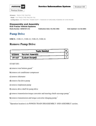
  • 1. Shutdown SIS Previous Screen Product: TRACK-TYPE TRACTOR Model: D10 TRACK-TYPE TRACTOR 76X Configuration: D10 TRACTOR / POWER SHIFT / 76X00359-UP (MACHINE) POWERED BY D348 ENGINE Disassembly and Assembly D10 Tractor Vehicle Systems Media Number -SENR7671-01 Publication Date -01/06/1982 Date Updated -12/10/2001 Pump Drive SMCS - 3108-11; 3108-12; 3108-15; 3108-16 Remove Pump Drive START BY: a) remove rear bottom guard * b) remove air conditioner compressor c) remove alternator d) remove fan drive pump e) remove implement pump f) remove drive shaft for pump drive g) remove transmission torque converter and steering clutch scavenge pump * h) remove transmission and torque converter charging pump * * Operation location is in POWER TRAIN DISASSEMBLY AND ASSEMBLY section. 1/13 D10 TRACTOR / POWER SHIFT / 76X00359-UP (MACHINE) POWERED BY D34... 2021/11/24 https://127.0.0.1/sisweb/sisweb/techdoc/techdoc_print_page.jsp?returnurl=/sis...
  • 2. 1. Remove bracket (1) from the pump drive. 2. Remove vee belts (2). 3. Remove five bolts (3) and drive shaft guard bracket (4). 4. Disconnect oil lines (5) and (6) from the pump drive. 5. Install tooling (A) on the top inside of the cab. Install nylon strap (7) to pump drive (8) and tooling (A). 2/13 D10 TRACTOR / POWER SHIFT / 76X00359-UP (MACHINE) POWERED BY D34... 2021/11/24 https://127.0.0.1/sisweb/sisweb/techdoc/techdoc_print_page.jsp?returnurl=/sis...
  • 3. 6. Disconnect oil line (9) from the pump drive. 7. Remove bolts (10) that hold the bottom mounting assembly to the frame. 8. Remove two bolts (11) that hold the top mounting assembly to the frame. 9. Use tooling (A) and remove pump drive (8) from the machine. The weight is 245 lb. (111 kg). Install Pump Drive 1. Use tooling (A) and a nylon strap and put pump drive (1) in position against the frame. 2. Install two bolts (2) that hold the top mounting assembly to the frame. 3/13 D10 TRACTOR / POWER SHIFT / 76X00359-UP (MACHINE) POWERED BY D34... 2021/11/24 https://127.0.0.1/sisweb/sisweb/techdoc/techdoc_print_page.jsp?returnurl=/sis...
  • 4. 3. Install bolts (4) that hold the bottom mounting assembly to the frame. 4. Connect oil line (3) to the pump drive. 5. Remove tooling (A) and nylon strap (5). 6. Connect oil lines (6) and (7) to the pump drive. 7. Install drive shaft guard bracket (8). 4/13 D10 TRACTOR / POWER SHIFT / 76X00359-UP (MACHINE) POWERED BY D34... 2021/11/24 https://127.0.0.1/sisweb/sisweb/techdoc/techdoc_print_page.jsp?returnurl=/sis...
  • 5. 8. Put vee belts (9) in position on the pulleys. 9. Install bracket (10) on the pump drive. END BY: a) install transmission and torque converter charging pump * b) install transmission, torque converter and steering clutch scavenge pump * c) install drive shaft for pump drive d) install implement pump e) install fan drive pump f) install alternator g) install air conditioning compressor h) install rear bottom guard * * Operation location is in POWER TRAIN DISASSEMBLY AND ASSEMBLY section. Disassemble Pump Drive 5/13 D10 TRACTOR / POWER SHIFT / 76X00359-UP (MACHINE) POWERED BY D34... 2021/11/24 https://127.0.0.1/sisweb/sisweb/techdoc/techdoc_print_page.jsp?returnurl=/sis...
  • 6. START BY: a) remove pump drive 1. Loosen nut (1) until washer (2) is approximately-1/8 in. (3.2 mm) away from yoke (3). Do not remove the nut at this time. 6/13 D10 TRACTOR / POWER SHIFT / 76X00359-UP (MACHINE) POWERED BY D34... 2021/11/24 https://127.0.0.1/sisweb/sisweb/techdoc/techdoc_print_page.jsp?returnurl=/sis...
  • 7. 2. Install tooling (A) on the yoke. Use tooling (A) to loosen the yoke from the taper. Remove tooling (A), nut (1), washer (2) and yoke (3). 3. Loosen nut (4) until washer (5) is approximately 1/8" (3.2 mm) away from pulley (6). Do not remove nut (4) at this time. 4. Install tooling (B) as shown. Use tooling (B) to loosen the pulley from the taper. Remove tooling (B), nut (4), washer (5) and pulley (6). Remove the key from the gear. 5. Use a hoist and turn the pump drive over. The weight is 245 lb. (111 kg). 6. Remove alternator bracket (7) from the pump drive. 7. Install tooling (C) and fasten a hoist as shown. Remove the bolts that hold the cover to the housing. Remove cover (8). The weight is 80 lb. (36 kg). 7/13 D10 TRACTOR / POWER SHIFT / 76X00359-UP (MACHINE) POWERED BY D34... 2021/11/24 https://127.0.0.1/sisweb/sisweb/techdoc/techdoc_print_page.jsp?returnurl=/sis...
  • 8. 8. Remove two lip type seals (9) from cover (8). 9. Use tooling (D) and remove bearing cups (10) from cover (8). 10. Remove gears (11), (12) and (13) from housing (14). 11. Use tooling (E) and remove bearing cone (15) from each side of the gears. 8/13 D10 TRACTOR / POWER SHIFT / 76X00359-UP (MACHINE) POWERED BY D34... 2021/11/24 https://127.0.0.1/sisweb/sisweb/techdoc/techdoc_print_page.jsp?returnurl=/sis...
  • 9. 12. Remove two lip type seals (16) from housing (14). 13. Use tooling (D) and remove three bearing cups (17) from housing (14). 14. Remove mount assemblies (18) from the housing if a replacement is needed. 9/13 D10 TRACTOR / POWER SHIFT / 76X00359-UP (MACHINE) POWERED BY D34... 2021/11/24 https://127.0.0.1/sisweb/sisweb/techdoc/techdoc_print_page.jsp?returnurl=/sis...
  • 10. Assemble Pump Drive 1. Clean and inspect all parts. Make a replacement of the parts if needed. Put clean oil on the lips of the seals, bearing cups and cones and gears. 2. Use tooling (A) and install two lip type seals (1) in housing (2). The lips of the seals must be toward the inside of the housing as shown. Turn the housing over. 3. Lower the temperature of bearing cups (3). Install bearing cups (3) in housing (2). 4. If mount assemblies (4) were removed, install the mount assemblies until the center line of bolt hole is 1.14 ± .010 in. (29.0 ± 0.25 mm) below surface (X). 5. Heat bearing cones (5) to a maximum temperature of 275°F (135°C). Install bearing cones (5) on gear (6). 10/13 D10 TRACTOR / POWER SHIFT / 76X00359-UP (MACHINE) POWERED BY D... 2021/11/24 https://127.0.0.1/sisweb/sisweb/techdoc/techdoc_print_page.jsp?returnurl=/sis...
  • 11. 6. Heat bearing cones (7) to a maximum temperature of 275°F (135°C). Install bearing cones (7) on gear (8). 7. Heat bearing cones (9) to a maximum temperature of 275°F (135°C). Install bearing cones (9) on gear (10). 8. Install gears (10), (8) and (6) in housing (2). See the illustrations for the correct way to install the gears in the housing. 9. Lower the temperature of three bearing cups (11). Install three bearing cups (11) in the cover. 11/13 D10 TRACTOR / POWER SHIFT / 76X00359-UP (MACHINE) POWERED BY D... 2021/11/24 https://127.0.0.1/sisweb/sisweb/techdoc/techdoc_print_page.jsp?returnurl=/sis...
  • 12. 10. Use tooling (A) and install two lip type seals (12) in cover (13). The lips of the seals must be toward the inside of the cover as shown. Turn the cover over. NOTE: If the studs were removed from the housing and the cover, install them and tighten the 1/2 in. studs to a torque of 40 ± 7 lb.ft. (55 ± 10 N·m) and 5/8 in. studs to a torque of 75 ± 11 lb.ft. (100 ± 15 N·m). 11. Install tooling (B) to the cover. Fasten a hoist to tooling (B). Put 7M7260 Liquid Gasket Material on the surfaces of housing (2) and cover (13) that make contact with each other. Install cover (13) on housing (2). 12. Install alternator bracket (14) on the pump drive. 13. Install the key in the gear. Make an alignment of the groove in pulley (17) with the key in the gear. Install pulley (17), washer (16) and nut (15). 12/13 D10 TRACTOR / POWER SHIFT / 76X00359-UP (MACHINE) POWERED BY D... 2021/11/24 https://127.0.0.1/sisweb/sisweb/techdoc/techdoc_print_page.jsp?returnurl=/sis...
  • 13. 14. Install yoke (20), washer (19) and nut (18) on the gear. END BY: a) install pump drive Copyright 1993 - 2021 Caterpillar Inc. All Rights Reserved. Private Network For SIS Licensees. Wed Nov 24 12:10:32 UTC+0800 2021 13/13 D10 TRACTOR / POWER SHIFT / 76X00359-UP (MACHINE) POWERED BY D... 2021/11/24 https://127.0.0.1/sisweb/sisweb/techdoc/techdoc_print_page.jsp?returnurl=/sis...
  • 14. Shutdown SIS Previous Screen Product: TRACK-TYPE TRACTOR Model: D10 TRACK-TYPE TRACTOR 76X Configuration: D10 TRACTOR / POWER SHIFT / 76X00359-UP (MACHINE) POWERED BY D348 ENGINE Disassembly and Assembly D10 Tractor Vehicle Systems Media Number -SENR7671-01 Publication Date -01/06/1982 Date Updated -12/10/2001 Pilot Control Valve SMCS - 5059-16; 5059-11; 5059-12; 5059-15 Remove Pilot Control Valve START BY: a) remove seat * * Operation location is in OPERATOR'S STATION DISASSEMBLY AND ASSEMBLY section. Hydraulic oil that is under pressure and hot can cause bodily injury. Move the control levers to relieve the pressure in the hydraulic system. Slowly loosen cap to release any pressure in the hydraulic tank. Let the hydraulic oil become cool before any lines are disconnected in the hydraulic system. 1. Remove cover (1) from the right side console. 1/9 D10 TRACTOR / POWER SHIFT / 76X00359-UP (MACHINE) POWERED BY D34... 2021/11/24 https://127.0.0.1/sisweb/sisweb/techdoc/techdoc_print_page.jsp?returnurl=/sis...
  • 15. 2. Remove bolts (4) that hold the flange retainers (3) and boots (2) to the pilot control valve. Pull boots (2) and retainers (3) up on the control rods. 3. Remove cotter pins (6) and pins (7) to disconnect control rods (5) from the valve spools of the pilot control valve. 4. Put identification on all the oil lines connected to the pilot control valve for correct installation. Disconnect all oil lines (10) from the pilot control valve. 5. Remove bolts (9) that hold the pilot control valve to the bracket. Remove pilot control valve (8) from the bracket. Install Pilot Control Valve 1. Install pilot control valve (1) on the bucket. 2/9 D10 TRACTOR / POWER SHIFT / 76X00359-UP (MACHINE) POWERED BY D34... 2021/11/24 https://127.0.0.1/sisweb/sisweb/techdoc/techdoc_print_page.jsp?returnurl=/sis...
  • 16. 2. Connect all oil lines (2) to the pilot control valve. 3. Move control rods (3) into position and install pins (5) and cotter pins (4) that connect the control rods to the valve spools of the pilot control valve. 4. Move boots (6) and retainers (7) into position on the flanges. Install bolts (8) that hold the flanges, retainers and boots to the pilot control valve. 5. Install cover (9) on the right side console. END BY: a) install seat * 3/9 D10 TRACTOR / POWER SHIFT / 76X00359-UP (MACHINE) POWERED BY D34... 2021/11/24 https://127.0.0.1/sisweb/sisweb/techdoc/techdoc_print_page.jsp?returnurl=/sis...
  • 17. * This operation location is in OPERATOR'S STATION DISASSEMBLY AND ASSEMBLY section. Disassemble Pilot Control Valve START BY: a) remove pilot control valve 1. Remove bolts (4). Make a separation of the manifolds from bulldozer tilt pilot control valve (3), ripper lift pilot control valve (2) and ripper tilt pilot control valve (1). 2. Remove housing (5) from the bulldozer tilt pilot control valve (3). Remove the O-ring seals. 3. Remove O-ring seal (6) and seal (7) from the housing. 4. Remove housing (8) from the bulldozer tilt pilot control valve body. 4/9 D10 TRACTOR / POWER SHIFT / 76X00359-UP (MACHINE) POWERED BY D34... 2021/11/24 https://127.0.0.1/sisweb/sisweb/techdoc/techdoc_print_page.jsp?returnurl=/sis...
  • 18. 5. Remove valve stem (9) from the bulldozer tilt pilot control valve body. There is spring pressure against retainers (10). 6. Remove retainers (10) and spring (11) from valve stem (9). 7. Remove housing (12) from ripper lift pilot control valve (2). 8. Remove the O-ring seal and the seal from the housing (see Step 3). 9. Remove housing (13) from ripper lift pilot control valve (2). 5/9 D10 TRACTOR / POWER SHIFT / 76X00359-UP (MACHINE) POWERED BY D34... 2021/11/24 https://127.0.0.1/sisweb/sisweb/techdoc/techdoc_print_page.jsp?returnurl=/sis...
  • 19. 10. Remove valve stem (14) from the ripper lift pilot control valve body. There is spring pressure against retainers (16). 11. Remove retainers (16) and spring (17) from valve stem (14). Make a note of hole (15) in stem (14). 12. Follow Steps 7 through 11 to disassemble ripper tilt pilot control valve (1). Assemble Pilot Control Valve 1. Clean and inspect all parts. Make a replacement of the parts that are worn or damaged. Put clean hydraulic oil on the valve parts. NOTE: Follow Steps 2 through 7 to assemble the ripper tilt pilot control valve and the ripper lift pilot control valve. The ripper lift pilot control valve is shown. 6/9 D10 TRACTOR / POWER SHIFT / 76X00359-UP (MACHINE) POWERED BY D34... 2021/11/24 https://127.0.0.1/sisweb/sisweb/techdoc/techdoc_print_page.jsp?returnurl=/sis...
  • 20. 2. Make sure valve stem (1) has hole (2) in it. 3. Install spring (4) and retainers (3) on valve stem (1). 4. Put valve stem (1) in position in the valve body. 5. Put the O-ring seal in position in housing (5). Install the housing on the valve body. 6. Use tooling (A) to install seal (7) in housing (6) as shown. Put O-ring seal (8) in position. Put clean hydraulic oil on the lips of seal (7). 7. Put housing (6) in position on the valve body. Put the O-ring seals in position on the valve body. 7/9 D10 TRACTOR / POWER SHIFT / 76X00359-UP (MACHINE) POWERED BY D34... 2021/11/24 https://127.0.0.1/sisweb/sisweb/techdoc/techdoc_print_page.jsp?returnurl=/sis...
  • 21. 8. Install the spring and retainers on valve stem (9). 9. Put valve stem (9) in position in the bulldozer tilt pilot control valve body. 10. Put the O-ring seal in position in housing (10). Install housing (10) on the bulldozer tilt pilot control valve body. 11. Install the seals in housing (11). See Step 6 for more details. 12. Put housing (11) in position on the bulldozer tilt pilot control valve body. 13. Put the O-ring seals (not shown) in position on manifold (15). 14. Put bulldozer tilt pilot control valve (12), ripper lift pilot control valve (13) and ripper tilt pilot control valve (16) in position. Install manifold (15) and manifold (14). END BY: a) install pilot control valve 8/9 D10 TRACTOR / POWER SHIFT / 76X00359-UP (MACHINE) POWERED BY D34... 2021/11/24 https://127.0.0.1/sisweb/sisweb/techdoc/techdoc_print_page.jsp?returnurl=/sis...
  • 22. Shutdown SIS Previous Screen Product: TRACK-TYPE TRACTOR Model: D10 TRACK-TYPE TRACTOR 76X Configuration: D10 TRACTOR / POWER SHIFT / 76X00359-UP (MACHINE) POWERED BY D348 ENGINE Disassembly and Assembly D10 Tractor Vehicle Systems Media Number -SENR7671-01 Publication Date -01/06/1982 Date Updated -12/10/2001 Bulldozer Control Valve SMCS - 6078-11; 6078-12; 6078-15; 6079-16 1/17 D10 TRACTOR / POWER SHIFT / 76X00359-UP (MACHINE) POWERED BY D34... 2021/11/24 https://127.0.0.1/sisweb/sisweb/techdoc/techdoc_print_page.jsp?returnurl=/sis...
  • 23. 2/17 D10 TRACTOR / POWER SHIFT / 76X00359-UP (MACHINE) POWERED BY D34... 2021/11/24 https://127.0.0.1/sisweb/sisweb/techdoc/techdoc_print_page.jsp?returnurl=/sis...
  • 24. Remove Bulldozer Control Valve START BY: a) remove seat and pressurizer housing 3/17 D10 TRACTOR / POWER SHIFT / 76X00359-UP (MACHINE) POWERED BY D34... 2021/11/24 https://127.0.0.1/sisweb/sisweb/techdoc/techdoc_print_page.jsp?returnurl=/sis...
  • 25. 1. Remove clamps (1) and (2) that hold hoses (3) in place. Move hoses (3) out of the way. NOTE: Put identification on all oil lines for correct installation. 2. Disconnect six oil lines (4) from the front of the bulldozer control valve. 3. Disconnect oil lines (5) from the left side of the bulldozer control valve. 4. Disconnect oil line (8) from the rear of the bulldozer control valve. 5. Disconnect two oil lines (7) from the left side of the bulldozer control valve. 6. Disconnect control rod (6) from the lever on the bulldozer control valve. 4/17 D10 TRACTOR / POWER SHIFT / 76X00359-UP (MACHINE) POWERED BY D34... 2021/11/24 https://127.0.0.1/sisweb/sisweb/techdoc/techdoc_print_page.jsp?returnurl=/sis...
  • 26. 7. Remove cover (9) from the right side console. 8. Remove bracket (10). 9. Install a 1/2"-13 NC forged eyebolt (11) [part of tooling (A)] in the top rear and center of the cab. Install the 6V2156 Link Bracket [part of tooling (A)] on the top of the bulldozer control valve. Fasten 5P9694 Ratchet Hoist (12) [part of tooling (A)] to the eyebolts and the bracket link. 10. Remove three bolts (14) and washers that hold the bulldozer control valve to the bracket. 11. Use tooling (A) and remove bulldozer control valve (13). The weight is 170 lb. (77 kg). Install Bulldozer Control Valve 5/17 D10 TRACTOR / POWER SHIFT / 76X00359-UP (MACHINE) POWERED BY D34... 2021/11/24 https://127.0.0.1/sisweb/sisweb/techdoc/techdoc_print_page.jsp?returnurl=/sis...
  • 27. 1. Use tooling (A) and put bulldozer control valve (1) in position. Make sure washers (2) are in position between the rubber pads and the bulldozer control valve. Install three bolts (7) that hold the bulldozer control valve to the bracket. 2. Install bracket (3). 3. Install cover (4) on the right side console. 4. Connect control rod (5) to the lever on the bulldozer control valve. 6/17 D10 TRACTOR / POWER SHIFT / 76X00359-UP (MACHINE) POWERED BY D34... 2021/11/24 https://127.0.0.1/sisweb/sisweb/techdoc/techdoc_print_page.jsp?returnurl=/sis...
  • 28. Suggest: If the above button click is invalid. Please download this document first, and then click the above link to download the complete manual. Thank you so much for reading
  • 29. 5. Connect two oil lines (6) to the right side of the bulldozer control valve. 6. Connect oil line (8) to the rear of the bulldozer control valve. 7. Connect oil lines (9) to the left side of the bulldozer control valve. 8. Connect six oil lines (10) to the front of the bulldozer control valve. 9. Put hoses (11) in their original positions and install clamps (12) and (13). END BY: a) install seat and pressurizer housing Disassemble Bulldozer Control Valve START BY: a) remove bulldozer control valve 7/17 D10 TRACTOR / POWER SHIFT / 76X00359-UP (MACHINE) POWERED BY D34... 2021/11/24 https://127.0.0.1/sisweb/sisweb/techdoc/techdoc_print_page.jsp?returnurl=/sis...