This document provides instructions for disassembling and assembling the final drive of a D9R track-type tractor. It describes removing components such as the planetary carrier, gears, shafts, and hub. Various tools are required, including link brackets, a push-puller tool group, driver group, and hydraulic cylinder assembly. Precautions are given for using hydraulic cylinders and puller studs during disassembly. The multi-step process includes pressing, lifting, and removing components from the planetary carrier, sun gear, and hub.
Ever been troubled by the blinking sign and didn’t know what to do?
Here’s a handy guide to dashboard symbols so that you’ll never be confused again!
Save them for later and save the trouble!
Ever been troubled by the blinking sign and didn’t know what to do?
Here’s a handy guide to dashboard symbols so that you’ll never be confused again!
Save them for later and save the trouble!
What Does the PARKTRONIC Inoperative, See Owner's Manual Message Mean for You...Autohaus Service and Sales
Learn what "PARKTRONIC Inoperative, See Owner's Manual" means for your Mercedes-Benz. This message indicates a malfunction in the parking assistance system, potentially due to sensor issues or electrical faults. Prompt attention is crucial to ensure safety and functionality. Follow steps outlined for diagnosis and repair in the owner's manual.
"Trans Failsafe Prog" on your BMW X5 indicates potential transmission issues requiring immediate action. This safety feature activates in response to abnormalities like low fluid levels, leaks, faulty sensors, electrical or mechanical failures, and overheating.
𝘼𝙣𝙩𝙞𝙦𝙪𝙚 𝙋𝙡𝙖𝙨𝙩𝙞𝙘 𝙏𝙧𝙖𝙙𝙚𝙧𝙨 𝙞𝙨 𝙫𝙚𝙧𝙮 𝙛𝙖𝙢𝙤𝙪𝙨 𝙛𝙤𝙧 𝙢𝙖𝙣𝙪𝙛𝙖𝙘𝙩𝙪𝙧𝙞𝙣𝙜 𝙩𝙝𝙚𝙞𝙧 𝙥𝙧𝙤𝙙𝙪𝙘𝙩𝙨. 𝙒𝙚 𝙝𝙖𝙫𝙚 𝙖𝙡𝙡 𝙩𝙝𝙚 𝙥𝙡𝙖𝙨𝙩𝙞𝙘 𝙜𝙧𝙖𝙣𝙪𝙡𝙚𝙨 𝙪𝙨𝙚𝙙 𝙞𝙣 𝙖𝙪𝙩𝙤𝙢𝙤𝙩𝙞𝙫𝙚 𝙖𝙣𝙙 𝙖𝙪𝙩𝙤 𝙥𝙖𝙧𝙩𝙨 𝙖𝙣𝙙 𝙖𝙡𝙡 𝙩𝙝𝙚 𝙛𝙖𝙢𝙤𝙪𝙨 𝙘𝙤𝙢𝙥𝙖𝙣𝙞𝙚𝙨 𝙗𝙪𝙮 𝙩𝙝𝙚 𝙜𝙧𝙖𝙣𝙪𝙡𝙚𝙨 𝙛𝙧𝙤𝙢 𝙪𝙨.
Over the 10 years, we have gained a strong foothold in the market due to our range's high quality, competitive prices, and time-lined delivery schedules.
Fleet management these days is next to impossible without connected vehicle solutions. Why? Well, fleet trackers and accompanying connected vehicle management solutions tend to offer quite a few hard-to-ignore benefits to fleet managers and businesses alike. Let’s check them out!
Comprehensive program for Agricultural Finance, the Automotive Sector, and Empowerment . We will define the full scope and provide a detailed two-week plan for identifying strategic partners in each area within Limpopo, including target areas.:
1. Agricultural : Supporting Primary and Secondary Agriculture
• Scope: Provide support solutions to enhance agricultural productivity and sustainability.
• Target Areas: Polokwane, Tzaneen, Thohoyandou, Makhado, and Giyani.
2. Automotive Sector: Partnerships with Mechanics and Panel Beater Shops
• Scope: Develop collaborations with automotive service providers to improve service quality and business operations.
• Target Areas: Polokwane, Lephalale, Mokopane, Phalaborwa, and Bela-Bela.
3. Empowerment : Focusing on Women Empowerment
• Scope: Provide business support support and training to women-owned businesses, promoting economic inclusion.
• Target Areas: Polokwane, Thohoyandou, Musina, Burgersfort, and Louis Trichardt.
We will also prioritize Industrial Economic Zone areas and their priorities.
Sign up on https://profilesmes.online/welcome/
To be eligible:
1. You must have a registered business and operate in Limpopo
2. Generate revenue
3. Sectors : Agriculture ( primary and secondary) and Automative
Women and Youth are encouraged to apply even if you don't fall in those sectors.
In this presentation, we have discussed a very important feature of BMW X5 cars… the Comfort Access. Things that can significantly limit its functionality. And things that you can try to restore the functionality of such a convenient feature of your vehicle.
Symptoms like intermittent starting and key recognition errors signal potential problems with your Mercedes’ EIS. Use diagnostic steps like error code checks and spare key tests. Professional diagnosis and solutions like EIS replacement ensure safe driving. Consult a qualified technician for accurate diagnosis and repair.
5 Warning Signs Your BMW's Intelligent Battery Sensor Needs AttentionBertini's German Motors
IBS monitors and manages your BMW’s battery performance. If it malfunctions, you will have to deal with an array of electrical issues in your vehicle. Recognize warning signs like dimming headlights, frequent battery replacements, and electrical malfunctions to address potential IBS issues promptly.
What Exactly Is The Common Rail Direct Injection System & How Does It WorkMotor Cars International
Learn about Common Rail Direct Injection (CRDi) - the revolutionary technology that has made diesel engines more efficient. Explore its workings, advantages like enhanced fuel efficiency and increased power output, along with drawbacks such as complexity and higher initial cost. Compare CRDi with traditional diesel engines and discover why it's the preferred choice for modern engines.
Core technology of Hyundai Motor Group's EV platform 'E-GMP'Hyundai Motor Group
What’s the force behind Hyundai Motor Group's EV performance and quality?
Maximized driving performance and quick charging time through high-density battery pack and fast charging technology and applicable to various vehicle types!
Discover more about Hyundai Motor Group’s EV platform ‘E-GMP’!
1. Product: TRACK-TYPE TRACTOR
Model: D9R TRACK-TYPE TRACTOR 8BL
Configuration: D9R Track-Type Tractor Power Shift 8BL01053-UP (MACHINE) POWERED BY 3408 Engine
Disassembly and Assembly
D9R Track-Type Tractor Power Train
Media Number -SENR5387-14 Publication Date -01/08/2018 Date Updated -30/08/2018
i05768467
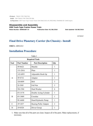
Final Drive Planetary Carrier (In Chassis) - Install
SMCS - 4092-012
Installation Procedure
Table 1
Required Tools
Tool Part Number Part Description Qty
A
5P-8622 Shackle 1
151-2816 Plate 1
142-6893 Adjustable Hook Gp 1
5P-8732 Adapter 1
1D-4609 Bolt 3
2J-3505 Full Nut 3
5H-1504 Hard Washer 6
B
6V-3170 Double Acting Cylinder 1
6V-3009 Crossbar 1
9U-6600 Hand Hydraulic Pump 1
C 1P-1837 Bearing Puller Adapter 2
D 1P-0520 Driver Group 1
1. Make sure that all of the parts are clean. Inspect all of the parts. Make replacements, if
necessary.
1/6
D9R Track-Type Tractor Power Shift 8BL01053-UP (MACHINE) POWERED BY 34...
2021/10/27
https://127.0.0.1/sisweb/sisweb/techdoc/techdoc_print_page.jsp?returnurl=/sis...
2. Illustration 1 g00627127
Illustration 2 g00627126
2. Lower the temperature of the sleeve bearing if sleeve bearing (19) has been removed. Install
the sleeve bearing with Tooling (D) .
3. Use Tooling (D) to install the lip seal in the hub. If Tooling (D) is not available, retainer
(15) may be installed. Ring (6) and a soft hammer may be used to install lip seal (18) .
4. Put clean oil on the lip of the seal.
2/6
D9R Track-Type Tractor Power Shift 8BL01053-UP (MACHINE) POWERED BY 34...
2021/10/27
https://127.0.0.1/sisweb/sisweb/techdoc/techdoc_print_page.jsp?returnurl=/sis...
3. Illustration 3 g01092639
5. Use Tooling (D) and a suitable press in order to install ring (16) in retainer (15) .
Illustration 4 g00627125
6. Install pins (17) in the holes that are in the hub.
Illustration 5 g00627123
3/6
D9R Track-Type Tractor Power Shift 8BL01053-UP (MACHINE) POWERED BY 34...
2021/10/27
https://127.0.0.1/sisweb/sisweb/techdoc/techdoc_print_page.jsp?returnurl=/sis...
4. 7. Put retainer (15) in position on the hub. Install bolts (14) that hold the retainer in place.
Tighten the bolts to a torque of 135 ± 15 N·m (100 ± 11 lb ft).
Illustration 6 g00627129
8. Remove Tooling (B) and Tooling (C) from the final drive.
Note: For assembly of the planetary carriers, see Disassembly and Assembly, "Final Drive -
Assemble".
Illustration 7 g00627120
9. Put sun gear (13) in position in the planetary carrier.
4/6
D9R Track-Type Tractor Power Shift 8BL01053-UP (MACHINE) POWERED BY 34...
2021/10/27
https://127.0.0.1/sisweb/sisweb/techdoc/techdoc_print_page.jsp?returnurl=/sis...
5. Illustration 8 g00627130
10. Put Tooling (A) in position on the planetary carrier. Make sure that O-ring seal (19) is in
position on the hub.
11. Make an alignment of the gears and slide planetary carrier (11) into the hub. Push the
planetary carrier inward. The planetary carriers should be approximately 2.54 cm (1.000
inch) from the final drive hub.
Illustration 9 g01092638
12. Install three bolts (10) that are 3/4 inch - 10 NC x 3.5 inch. The bolts should be installed at
even distances from each other. Remove Tooling (A) . Install bolts (8) that hold the
planetary carrier in position. Remove bolts (10) and install the other three bolts that hold the
planetary carrier in position. Tighten bolts (8) to a torque of 430 ± 60 N·m (317 ± 44 lb ft).
5/6
D9R Track-Type Tractor Power Shift 8BL01053-UP (MACHINE) POWERED BY 34...
2021/10/27
https://127.0.0.1/sisweb/sisweb/techdoc/techdoc_print_page.jsp?returnurl=/sis...
6. Illustration 10 g01092637
13. Remove three bolts (7) from the center of cover (6) . Remove three bolts (9) and cover (6)
from the final drive.
Illustration 11 g00627133
14. Remove spiral lockring (5) , ring (4) , and retainer (3) .
End By: Install the axles. See Disassembly and Assembly, "Axle - Install".
6/6
D9R Track-Type Tractor Power Shift 8BL01053-UP (MACHINE) POWERED BY 34...
2021/10/27
https://127.0.0.1/sisweb/sisweb/techdoc/techdoc_print_page.jsp?returnurl=/sis...
7. Product: TRACK-TYPE TRACTOR
Model: D9R TRACK-TYPE TRACTOR 8BL
Configuration: D9R Track-Type Tractor Power Shift 8BL01053-UP (MACHINE) POWERED BY 3408 Engine
Disassembly and Assembly
D9R Track-Type Tractor Power Train
Media Number -SENR5387-14 Publication Date -01/08/2018 Date Updated -30/08/2018
i03477582
Final Drive - Disassemble
SMCS - 4050-015
Disassembly Procedure
Table 1
Required Tools
Tool Part Number Part Description Qty
A 138-7575 Link Bracket 3
B
8B-7548 Push-Puller Tool Group 1
8H-0684 Ratchet Wrench 1
8B-7554 Bearing Cup Puller 1
C 138-7573 Link Bracket 3
D 1P-0520 Driver Group 1
E
1P-0527 Plate 1
6V-3160 Hydraulic Cylinder Gp 1
5P-9695 Pressure Plate 1
2S-4680 Stud 3
5H-1504 Hard Washer 3
6B-6682 Full Nut 3
FT-1409 Spacer 6
9U-6600 Hand Hydraulic Pump 1
F 138-7574 Link Bracket 2
1/13
D9R Track-Type Tractor Power Shift 8BL01053-UP (MACHINE) POWERED BY 34...
2021/10/27
https://127.0.0.1/sisweb/sisweb/techdoc/techdoc_print_page.jsp?returnurl=/sis...
8. Start By:
a. Remove the final drive. See Disassembly and Assembly, "Final Drive - Remove".
When you are using hydraulic cylinders and puller studs, always ensure
that the rated capacity of the puller stud meets or exceeds the rated
capacity of the hydraulic cylinder. If the puller stud does not meet or
exceed the rated capacity of the hydraulic cylinder, a sudden failure of
the puller stud could occur. The sudden failure of the puller stud could
result in personal injury or death.
NOTICE
Do not use threaded rods that have not been hardened as tooling with
hydraulic cylinders. The maximum rated tonnage should be stamped
on one end of the puller studs. Do not use threaded rods that have not
been stamped with the rated tonnage.
2/13
D9R Track-Type Tractor Power Shift 8BL01053-UP (MACHINE) POWERED BY 34...
2021/10/27
https://127.0.0.1/sisweb/sisweb/techdoc/techdoc_print_page.jsp?returnurl=/sis...
9. Illustration 1 g01086838
1. Install Tooling (A) on the planetary carrier. Fasten a suitable lifting device to Tooling (A).
2. Remove bolts (1) that hold the planetary carrier to the hub.
3. Remove planetary carrier (2) from the hub. The weight is approximately 170 kg (375 lb).
Illustration 2 g00627501
4. Remove bolts (3) and three plates (4). Remove the O-ring seals from the plates.
3/13
D9R Track-Type Tractor Power Shift 8BL01053-UP (MACHINE) POWERED BY 34...
2021/10/27
https://127.0.0.1/sisweb/sisweb/techdoc/techdoc_print_page.jsp?returnurl=/sis...
10. Illustration 3 g00627502
5. Use a suitable press to remove shafts (5) from the planetary carrier.
Illustration 4 g00627505
6. Remove gears (7) from the planetary carrier.
7. Remove bearing cones (6) from each side of gears (7).
Illustration 5 g01086839
8. Remove bearing cups (8) from each side of gears (7) with Tooling (B).
4/13
D9R Track-Type Tractor Power Shift 8BL01053-UP (MACHINE) POWERED BY 34...
2021/10/27
https://127.0.0.1/sisweb/sisweb/techdoc/techdoc_print_page.jsp?returnurl=/sis...
11. Illustration 6 g01086869
9. Install Tooling (C) on the planetary carrier, as shown. Fasten an appropriate lifting device to
Tooling (C).
Note: There is a sun gear in the middle of the planetary carrier. The sun gear is free to fall if
the gear stays with the planetary carrier.
10. Remove sun gear (10) and planetary carrier (9) as an assembly from the hub. The weight is
approximately 95 kg (210 lb).
Illustration 7 g00627509
11. Remove spiral ring (11) from the sun gear.
5/13
D9R Track-Type Tractor Power Shift 8BL01053-UP (MACHINE) POWERED BY 34...
2021/10/27
https://127.0.0.1/sisweb/sisweb/techdoc/techdoc_print_page.jsp?returnurl=/sis...
12. Illustration 8 g01086870
12. Fasten a suitable lifting device in order to remove planetary carrier (9) from sun gear (10).
The weight of the planetary carrier is approximately 68 kg (150 lb).
Illustration 9 g00627511
13. Remove bolts (12) and plates (13).
6/13
D9R Track-Type Tractor Power Shift 8BL01053-UP (MACHINE) POWERED BY 34...
2021/10/27
https://127.0.0.1/sisweb/sisweb/techdoc/techdoc_print_page.jsp?returnurl=/sis...
13. Illustration 10 g01086871
14. Use a suitable press to remove shafts (14) from the planetary carrier.
15. Remove gears (15) from the planetary carrier.
Illustration 11 g00627520
16. Remove bearing cone (16) from each side of gears (15).
Illustration 12 g00627522
17. Remove bearing cup (17) from each side of gear (15).
7/13
D9R Track-Type Tractor Power Shift 8BL01053-UP (MACHINE) POWERED BY 34...
2021/10/27
https://127.0.0.1/sisweb/sisweb/techdoc/techdoc_print_page.jsp?returnurl=/sis...
14. Illustration 13 g00627524
18. Remove lockring (18) from each of the gears.
Illustration 14 g00627525
19. Remove sun gear (19).
Illustration 15 g00627542
20. Remove bolts and retainer (20). Use Tooling (D) and a suitable press to remove ring (21)
from retainer (20) if a replacement of either part is needed.
8/13
D9R Track-Type Tractor Power Shift 8BL01053-UP (MACHINE) POWERED BY 34...
2021/10/27
https://127.0.0.1/sisweb/sisweb/techdoc/techdoc_print_page.jsp?returnurl=/sis...
15. Illustration 16 g00627543
21. Use a magnet to remove pins (22) from the hub.
22. Install Tooling (A) on the hub. Fasten an appropriate lifting device to Tooling (A). Remove
the hub and ring gear (23) from hub (24). The weight of the hub and ring gear is
approximately 136 kg (300 lb).
Illustration 17 g01096464
23. Turn over the hub and the ring gear. Remove retainer ring (23) from the hub.
9/13
D9R Track-Type Tractor Power Shift 8BL01053-UP (MACHINE) POWERED BY 34...
2021/10/27
https://127.0.0.1/sisweb/sisweb/techdoc/techdoc_print_page.jsp?returnurl=/sis...
16. Illustration 18 g01086875
24. Install Tooling (A) on hub (25). Fasten an appropriate lifting device to Tooling (A). Remove
hub (25) from ring (24). The weight of the hub is approximately 41 kg (90 lb).
Illustration 19 g01096496
25. Install Tooling (E). The rod end should be down. Make sure that the hydraulic cylinder is in
the center of the 5P-9695 Pressure Plate. Make sure that the 1P-0527 Plate is between the
hydraulic cylinder and the hub.
26. Loosen hub (26) from hub (28) with Tooling (E) until the bearing is free. It is possible that
the bearing cone will need to be heated with a torch.
10/13
D9R Track-Type Tractor Power Shift 8BL01053-UP (MACHINE) POWERED BY ...
2021/10/27
https://127.0.0.1/sisweb/sisweb/techdoc/techdoc_print_page.jsp?returnurl=/sis...
17. Illustration 20 g00627549
27. Remove Tooling (E). Remove bearing cone (27).
Illustration 21 g01086876
28. Install Tooling (F) on hub (26). Fasten a suitable lifting device to Tooling (F). Remove hub
(26) from hub (28). The weight of the hub is approximately 352 kg (775 lb).
11/13
D9R Track-Type Tractor Power Shift 8BL01053-UP (MACHINE) POWERED BY ...
2021/10/27
https://127.0.0.1/sisweb/sisweb/techdoc/techdoc_print_page.jsp?returnurl=/sis...
18. Illustration 22 g00627551
29. Remove Duo-Cone seal (29) from the hub.
Illustration 23 g00627552
30. Remove bearing cup (31) from the hub with a punch and a hammer.
31. Turn over the hub. Remove bearing cup (30) from the hub with a punch and a hammer.
Illustration 24 g00627553
32. Remove Duo-Cone seal (32) from hub (28). Put identification on the seal for installation.
12/13
D9R Track-Type Tractor Power Shift 8BL01053-UP (MACHINE) POWERED BY ...
2021/10/27
https://127.0.0.1/sisweb/sisweb/techdoc/techdoc_print_page.jsp?returnurl=/sis...
19. Illustration 25 g00627555
33. If necessary, remove bearing cone (33) from the hub. Securely support the hub. Heat the
circumference of the cone evenly. Do not stop the torch and heat the cone in any one place.
If the hub is heated excessively during bearing removal 150 °C (300 °F), the future service
life may be reduced. If the bearing cone is heated in any one place to a temperature above
120 °C (248 °F), the heat treatment will be destroyed. A bearing failure is probable if the
bearing is used again.
Illustration 26 g00627556
34. Remove lip seal (34) from the hub.
35. Inspect sleeve bearing (35). If necessary, remove the sleeve bearing from the hub.
13/13
D9R Track-Type Tractor Power Shift 8BL01053-UP (MACHINE) POWERED BY ...
2021/10/27
https://127.0.0.1/sisweb/sisweb/techdoc/techdoc_print_page.jsp?returnurl=/sis...
20. Product: TRACK-TYPE TRACTOR
Model: D9R TRACK-TYPE TRACTOR 8BL
Configuration: D9R Track-Type Tractor Power Shift 8BL01053-UP (MACHINE) POWERED BY 3408 Engine
Disassembly and Assembly
D9R Track-Type Tractor Power Train
Media Number -SENR5387-14 Publication Date -01/08/2018 Date Updated -30/08/2018
i02140464
Final Drive - Assemble
SMCS - 4050-016
Assembly Procedure
Table 1
Required Tools
Tool Part Number Part Description Qty
A 138-7575 Link Bracket 3
C 138-7573 Link Bracket 3
D 1P-0520 Driver Group 1
F 138-7574 Link Bracket 2
G 1U-5934 Duo-Cone Seal Installer As 1
H 140-2286 Spacer 1
J 169-0503 Installation Kit 1
1/14
D9R Track-Type Tractor Power Shift 8BL01053-UP (MACHINE) POWERED BY 34...
2021/10/27
https://127.0.0.1/sisweb/sisweb/techdoc/techdoc_print_page.jsp?returnurl=/sis...
21. Illustration 1 g00642301
Note: Lower the temperature of the sleeve bearing. Use Tooling (D) to install sleeve
bearing (35).
1. Inspect all of the parts for damage. Make replacements, if necessary. Ensure that all of the
parts are clean.
Illustration 2 g01096508
2. Install lip seal (34) in the hub with Tooling (D).
2/14
D9R Track-Type Tractor Power Shift 8BL01053-UP (MACHINE) POWERED BY 34...
2021/10/27
https://127.0.0.1/sisweb/sisweb/techdoc/techdoc_print_page.jsp?returnurl=/sis...
22. Illustration 3 g00627559
3. Raise bearing cone (33) to a maximum temperature of 135 °C (275 °F). Install bearing cone
(33) on hub (28).
Note: Before you install any of the Duo-Cone seals, see Installation of the Duo-Cone
Floating Seals in this module. Use Tooling (J) for preparation of the seal.
Illustration 4 g01096509
4. Use Tooling (G) to install Duo-Cone seal (32) on the hub, as shown.
Illustration 5 g00627562
3/14
D9R Track-Type Tractor Power Shift 8BL01053-UP (MACHINE) POWERED BY 34...
2021/10/27
https://127.0.0.1/sisweb/sisweb/techdoc/techdoc_print_page.jsp?returnurl=/sis...
23. 5. Lower the temperature of bearing cups (30) and (31). Install bearing cups (30) and (31) in
hub (24). Check with a 0.038 mm (0.0015 inch) feeler gauge. Ensure that the bearing cup is
seated against the bottom of the bore all the way around.
Illustration 6 g01096510
6. Use Tooling (G) to install Duo-Cone seal (29) in hub (24).
Illustration 7 g01086876
Note: Do not put hub (24) on the Duo-Cone seal when the hub is turned over.
4/14
D9R Track-Type Tractor Power Shift 8BL01053-UP (MACHINE) POWERED BY 34...
2021/10/27
https://127.0.0.1/sisweb/sisweb/techdoc/techdoc_print_page.jsp?returnurl=/sis...
24. 7. Turn over hub (24). Install Tooling (F) in the hub and fasten a suitable lifting device to the
Tooling. Put hub (24) in position on hub (28), as shown.
Illustration 8 g00627566
8. Raise bearing cone (27) to a maximum temperature of 135 °C (275 °F). Install bearing cone
(27) on the hub.
Illustration 9 g01096511
9. Put Tooling (H) in position while the bearing cone is still hot. Install retainer (20). Turn the
hub while the bolts that hold the retainer are tightened to a torque of 135 ± 15 N·m
(100 ± 11 lb ft). Permit the bearing cone to return to room temperature before the retainer
and Tooling (F) are removed.
5/14
D9R Track-Type Tractor Power Shift 8BL01053-UP (MACHINE) POWERED BY 34...
2021/10/27
https://127.0.0.1/sisweb/sisweb/techdoc/techdoc_print_page.jsp?returnurl=/sis...
25. Illustration 10 g01086875
10. Install Tooling (A) on hub (25). Fasten an suitable lifting device to Tooling (A). Put hub
(25) in position in ring gear (24).
Illustration 11 g01096464
11. Install retainer ring (23) in the groove in ring gear (24).
6/14
D9R Track-Type Tractor Power Shift 8BL01053-UP (MACHINE) POWERED BY 34...
2021/10/27
https://127.0.0.1/sisweb/sisweb/techdoc/techdoc_print_page.jsp?returnurl=/sis...
26. Illustration 12 g01087059
12. Turn over the hub and the gear. Install Tooling (A) onto hub (25). Fasten an suitable lifting
device to Tooling (A). Install ring gear (24) and the hub as a unit.
Illustration 13 g00627576
13. Put pins (22) in position in the hub.
7/14
D9R Track-Type Tractor Power Shift 8BL01053-UP (MACHINE) POWERED BY 34...
2021/10/27
https://127.0.0.1/sisweb/sisweb/techdoc/techdoc_print_page.jsp?returnurl=/sis...
27. Illustration 14 g00627578
14. If a replacement is needed, use Tooling (A) and a suitable press to install ring (21) in
retainer (20).
15. Put retainer (20) in position on the hub.
Illustration 15 g00627580
16. Install bolts (35) that hold retainer (20) in position. Tighten the bolts to a torque of
135 ± 15 N·m (100 ± 11 lb ft).
Illustration 16 g00627582
8/14
D9R Track-Type Tractor Power Shift 8BL01053-UP (MACHINE) POWERED BY 34...
2021/10/27
https://127.0.0.1/sisweb/sisweb/techdoc/techdoc_print_page.jsp?returnurl=/sis...
28. 17. Use feeler gauge (36) to measure the distance between retainer (20) and pins (22). The
clearance must be 0.08 ± 0.05 mm (0.003 ± 0.002 inch).
Note: There must be metal to metal contact between hub (28) and retainer (20). If there is
no gap, bearing cone (27) was not pressed correctly with Tooling (H). See step 9. A gap
between pins (22) and retainer (20) allows metal to metal contact between retainer (20) and
hub (28).
Illustration 17 g00627583
18. Install lockring (18) in gears (15).
Illustration 18 g00627522
19. Lower the temperature of bearing cups (17). Install bearing cups (17) in gears (15).
9/14
D9R Track-Type Tractor Power Shift 8BL01053-UP (MACHINE) POWERED BY 34...
2021/10/27
https://127.0.0.1/sisweb/sisweb/techdoc/techdoc_print_page.jsp?returnurl=/sis...
29. Suggest:
If the above button click is invalid.
Please download this document
first, and then click the above link
to download the complete manual.
Thank you so much for reading