
Recommended
More Related Content
Similar to Caterpillar Cat 988B Wheel Loader (Prefix 50W) Service Repair Manual Instant Download (50W06041 and up).pdf
Similar to Caterpillar Cat 988B Wheel Loader (Prefix 50W) Service Repair Manual Instant Download (50W06041 and up).pdf (20)
More from ting1499041267
More from ting1499041267 (20)
Recently uploaded
Recently uploaded (20)
Caterpillar Cat 988B Wheel Loader (Prefix 50W) Service Repair Manual Instant Download (50W06041 and up).pdf
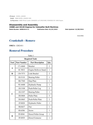
- 1. Product: WHEEL LOADER Model: 988B WHEEL LOADER 50W Configuration: 988B Wheel Loader 50W06041-UP (MACHINE) POWERED BY 3408 Engine Disassembly and Assembly 3408E and 3412E Engines for Caterpillar Built Machines Media Number -SENR1013-11 Publication Date -01/07/2015 Date Updated -22/08/2016 i01615902 Crankshaft - Remove SMCS - 1202-011 Removal Procedure Table 1 Required Tools Tool Part Number Part Description Qty A 171-4660 Bracket 2 4C-9832 Engine Rollover Stand 1 B 138-7573 Link Bracket 2 C 1H-3110 Bearing Puller 1 8B-7560 Step Plate 1 9U-6600 Hydraulic Pump 1 1H-3108 Push-Puller Leg 2 1H-3107 Bearing Puller 1 3H-0468 Puller Plate 5 3H-0465 Push-Puller Plate 2 1P-0820 Hydraulic Puller 1 5B-0637 Nut 1 8S-6586 Screw 1 D 5P-0944 Dowel Puller Group 1 5P-0939 Dowel Extractor 1 1/4 988B Wheel Loader 50W06041-UP (MACHINE) POWERED BY 3408 Engine(SEBP... 2021/12/5 https://127.0.0.1/sisweb/sisweb/techdoc/techdoc_print_page.jsp?returnurl=/sis...
- 2. Start By: a. Remove the front housing. Refer to Disassembly and Assembly, "Housing (Front) - Remove". b. Remove the rear gear group. Refer to Disassembly and Assembly, "Gear Group (Rear) - Remove". c. Remove the crankshaft main bearings. Refer to Disassembly and Assembly, "Crankshaft Main Bearings - Remove". d. Remove the connecting rod bearings. Refer to Disassembly and Assembly, "Connecting Rod Bearings - Remove". NOTICE Keep all parts clean from contaminants. Contaminants may cause rapid wear and shortened component life. Illustration 1 g00720077 Typical example 1. The engine should be in position on Tool (A). 2. Push the piston assemblies toward the cylinder heads. 2/4 988B Wheel Loader 50W06041-UP (MACHINE) POWERED BY 3408 Engine(SEBP... 2021/12/5 https://127.0.0.1/sisweb/sisweb/techdoc/techdoc_print_page.jsp?returnurl=/sis...
- 3. Illustration 2 g00584893 Typical example 3. Be sure that the "V" timing marks are aligned on idler gear (2) and crankshaft gear (1). Illustration 3 g00720087 Typical example 4. Install Tools (B) on each end of the crankshaft with a front pulley bolt. 5. Fasten a hoist to crankshaft (3). Remove the crankshaft from the cylinder block. The 3408E crankshaft weighs 150 kg (325 lb). The 3412E crankshaft weighs 215 kg (474 lb). 3/4 988B Wheel Loader 50W06041-UP (MACHINE) POWERED BY 3408 Engine(SEBP... 2021/12/5 https://127.0.0.1/sisweb/sisweb/techdoc/techdoc_print_page.jsp?returnurl=/sis...
- 4. Illustration 4 g00584906 Typical example 6. Use Tool (C) to remove crankshaft gear (4). Use Tool (D) to remove the dowel that is under gear (4) if a replacement is necessary. Illustration 5 g00584908 Typical example 7. Remove pin (5) from the crankshaft with Tool (D) if the pin is worn or damaged. 4/4 988B Wheel Loader 50W06041-UP (MACHINE) POWERED BY 3408 Engine(SEBP... 2021/12/5 https://127.0.0.1/sisweb/sisweb/techdoc/techdoc_print_page.jsp?returnurl=/sis...
- 5. Product: WHEEL LOADER Model: 988B WHEEL LOADER 50W Configuration: 988B Wheel Loader 50W06041-UP (MACHINE) POWERED BY 3408 Engine Disassembly and Assembly 3408E and 3412E Engines for Caterpillar Built Machines Media Number -SENR1013-11 Publication Date -01/07/2015 Date Updated -22/08/2016 i07509804 Crankshaft - Install SMCS - 1202-012 Installation Procedure Table 1 Required Tools Tool Part Number Part Description Qty A 138-7573 Link Bracket 2 NOTICE Keep all parts clean from contaminants. Contaminants may cause rapid wear and shortened component life. 1/4 988B Wheel Loader 50W06041-UP (MACHINE) POWERED BY 3408 Engine(SEBP... 2021/12/5 https://127.0.0.1/sisweb/sisweb/techdoc/techdoc_print_page.jsp?returnurl=/sis...
- 6. Illustration 1 g00585091 Typical example 1. Install pin (5) in the crankshaft. Maximum protrusion of pin (5) from the crankshaft face ... 8.4 mm (0.33 inch) 2. Install dowel (6) in the crankshaft. Protrusion of dowel (6) from the crankshaft face ... 4.1 ± 0.5 mm (0.16 ± 0.02 inch) Illustration 2 g00585099 Typical example 3. Heat crankshaft gear (4) to a maximum temperature of 205 °C (400 °F). Install gear (4) on the crankshaft with the keyway in alignment with dowel (2). The timing mark "V" should face away from the crankshaft. Note: Press crankshaft gear (4) until the gear is seated again the lip. 4. Clean the cylinder block and the main bearing caps thoroughly. 2/4 988B Wheel Loader 50W06041-UP (MACHINE) POWERED BY 3408 Engine(SEBP... 2021/12/5 https://127.0.0.1/sisweb/sisweb/techdoc/techdoc_print_page.jsp?returnurl=/sis...
- 7. Note: Install the main bearings dry when clearance checks are made. Put clean engine oil on the main bearings for final assembly. 5. Install the upper halves of the main bearings in the cylinder block. Note: Ensure that the main bearings are installed so that the bearing tabs fit into the notch in the cylinder block. The upper halves of the main bearings have the oil groove and the oil hole. Illustration 3 g00585103 Typical example 6. Install Tools (A) on each end of the crankshaft with a front pulley bolt. Fasten a hoist to crankshaft (3). Illustration 4 g00584893 Typical example 7. Install crankshaft (3) with the "V" mark on crankshaft gear (1) in alignment with the "V" mark on idler gear (2). End By: a. Install the connecting rod bearings. Refer to Disassembly and Assembly, "Connecting Rod Bearings - Install". 3/4 988B Wheel Loader 50W06041-UP (MACHINE) POWERED BY 3408 Engine(SEBP... 2021/12/5 https://127.0.0.1/sisweb/sisweb/techdoc/techdoc_print_page.jsp?returnurl=/sis...
- 8. b. Install the crankshaft main bearings. Refer to Disassembly and Assembly, "Crankshaft Main Bearings - Install". c. Install the rear gear group. Refer to Disassembly and Assembly, "Gear Group (Rear) - Install". d. Install the front housing. Refer to Disassembly and Assembly, "Housing (Front) - Install". 4/4 988B Wheel Loader 50W06041-UP (MACHINE) POWERED BY 3408 Engine(SEBP... 2021/12/5 https://127.0.0.1/sisweb/sisweb/techdoc/techdoc_print_page.jsp?returnurl=/sis...
- 9. Product: WHEEL LOADER Model: 988B WHEEL LOADER 50W Configuration: 988B Wheel Loader 50W06041-UP (MACHINE) POWERED BY 3408 Engine Disassembly and Assembly 3408E and 3412E Engines for Caterpillar Built Machines Media Number -SENR1013-11 Publication Date -01/07/2015 Date Updated -22/08/2016 i05977048 Bearing Clearance - Check SMCS - 1203-535; 1219-535 Measurement Procedure Table 1 Required Tools Tool Part Number Part Description Qty A 198-9142 Plastic Gauge (Green) 0.025 to 0.076 mm (0.001 to 0.003 inch) 1 198-9143 Plastic Gauge (Red) 0.051 to 0.152 mm (0.002 to 0.006 inch) 1 198-9144 Plastic Gauge (Blue) 0.102 to 0.229 mm (0.004 to 0.009 inch) 1 198-9145 Plastic Gauge (Yellow) 0.230 to 0.510 mm (0.009 to 0.020 inch) 1 Note: Plastic gauge may not be necessary when the engine is in the chassis. NOTICE Keep all parts clean from contaminants. Contaminants may cause rapid wear and shortened component life. 1/3 988B Wheel Loader 50W06041-UP (MACHINE) POWERED BY 3408 Engine(SEBP... 2021/12/5 https://127.0.0.1/sisweb/sisweb/techdoc/techdoc_print_page.jsp?returnurl=/sis...
- 10. Note: Cat does not recommend the checking of the actual bearing clearances particularly on small engines. This is because of the possibility of obtaining inaccurate results and the possibility of damaging the bearing or the journal surfaces. Each Cat engine bearing is quality checked for specific wall thickness. Note: The measurements should be within specifications and the correct bearings should be used. If the crankshaft journals and the bores for the block and the rods were measured during disassembly, no further checks are necessary. However, if the technician still wants to measure the bearing clearances, Tooling (A) is an acceptable method. Tooling (A) is less accurate on journals with small diameters if clearances are less than 0.10 mm (0.004 inch). NOTICE Lead wire, shim stock or a dial bore gauge can damage the bearing surfaces. The technician must be very careful to use Tooling (A) correctly. The following points must be remembered: • Ensure that the backs of the bearings and the bores are clean and dry. • Ensure that the bearing locking tabs are properly seated in the tab grooves. • The crankshaft must be free of oil at the contact points of Tooling (A). 1. Put a piece of Tooling (A) on the crown of the bearing that is in the cap. Note: Do not allow Tooling (A) to extend over the edge of the bearing. 2. Use the correct torque-turn specifications in order to install the bearing cap. Do not use an impact wrench. Be careful not to dislodge the bearing when the cap is installed. Note: Do not turn the crankshaft when Tooling (A) is installed. 3. Carefully remove the cap, but do not remove Tooling (A). Measure the width of Tooling (A) while Tooling (A) is in the bearing cap or on the crankshaft journal. Refer to Illustration 1. 2/3 988B Wheel Loader 50W06041-UP (MACHINE) POWERED BY 3408 Engine(SEBP... 2021/12/5 https://127.0.0.1/sisweb/sisweb/techdoc/techdoc_print_page.jsp?returnurl=/sis...
- 11. Illustration 1 g01152855 Typical Example 4. Remove all of Tooling (A) before you install the bearing cap. Note: When Tooling (A) is used, the readings can sometimes be unclear. For example, all parts of Tooling (A) are not the same width. Measure the major width in order to ensure that the parts are within the specification range. Refer to Specifications Manual, "Connecting Rod Bearing Journal" and Specifications Manual, "Main Bearing Journal" for the correct clearances. 3/3 988B Wheel Loader 50W06041-UP (MACHINE) POWERED BY 3408 Engine(SEBP... 2021/12/5 https://127.0.0.1/sisweb/sisweb/techdoc/techdoc_print_page.jsp?returnurl=/sis...
- 12. Product: WHEEL LOADER Model: 988B WHEEL LOADER 50W Configuration: 988B Wheel Loader 50W06041-UP (MACHINE) POWERED BY 3408 Engine Disassembly and Assembly 3408E and 3412E Engines for Caterpillar Built Machines Media Number -SENR1013-11 Publication Date -01/07/2015 Date Updated -22/08/2016 i01055901 Atmospheric Pressure Sensor - Remove and Install SMCS - 1923-010 Removal Procedure NOTICE Keep all parts clean from contaminants. Contaminants may cause rapid wear and shortened component life. Illustration 1 g00548090 1. Disconnect atmospheric pressure sensor connector (1). 2. Remove nut (3) and the washer. 3. Remove clamp (2). 1/2 988B Wheel Loader 50W06041-UP (MACHINE) POWERED BY 3408 Engine(SEBP... 2021/12/5 https://127.0.0.1/sisweb/sisweb/techdoc/techdoc_print_page.jsp?returnurl=/sis...
- 13. 4. Remove atmospheric pressure sensor (4). Installation Procedure NOTICE Keep all parts clean from contaminants. Contaminants may cause rapid wear and shortened component life. Illustration 2 g00548090 1. Install atmospheric pressure sensor (4). 2. Install clamp (2). 3. Install the washer and nut (3). 4. Connect atmospheric pressure sensor connector (1) to the engine wiring harness. 2/2 988B Wheel Loader 50W06041-UP (MACHINE) POWERED BY 3408 Engine(SEBP... 2021/12/5 https://127.0.0.1/sisweb/sisweb/techdoc/techdoc_print_page.jsp?returnurl=/sis...
- 14. Product: WHEEL LOADER Model: 988B WHEEL LOADER 50W Configuration: 988B Wheel Loader 50W06041-UP (MACHINE) POWERED BY 3408 Engine Disassembly and Assembly 3408E and 3412E Engines for Caterpillar Built Machines Media Number -SENR1013-11 Publication Date -01/07/2015 Date Updated -22/08/2016 i01054519 Coolant Temperature Sensor - Remove and Install SMCS - 1906-010 Removal Procedure NOTICE Care must be taken to ensure that fluids are contained during performance of inspection, maintenance, testing, adjusting and repair of the product. Be prepared to collect the fluid with suitable containers before opening any compartment or disassembling any component containing fluids. Refer to Special Publication, NENG2500, "Caterpillar Dealer Service Tool Catalog" for tools and supplies suitable to collect and contain fluids on Caterpillar products. Dispose of all fluids according to local regulations and mandates. NOTICE Keep all parts clean from contaminants. Contaminants may cause rapid wear and shortened component life. 1/3 988B Wheel Loader 50W06041-UP (MACHINE) POWERED BY 3408 Engine(SEBP... 2021/12/5 https://127.0.0.1/sisweb/sisweb/techdoc/techdoc_print_page.jsp?returnurl=/sis...
- 15. Illustration 1 g00547145 1. Remove wire tie (2). 2. Disconnect coolant temperature sensor connector (3) from the engine wiring harness. 3. Remove coolant temperature sensor (1) from the engine. Installation Procedure NOTICE Keep all parts clean from contaminants. Contaminants may cause rapid wear and shortened component life. Illustration 2 g00547145 1. Install coolant temperature sensor (1) in the engine. 2. Tighten the coolant temperature sensor to a torque of 20 ± 3 N·m (15 ± 2 lb ft). 3. Connect coolant temperature sensor connector (3) to the engine wiring harness. 2/3 988B Wheel Loader 50W06041-UP (MACHINE) POWERED BY 3408 Engine(SEBP... 2021/12/5 https://127.0.0.1/sisweb/sisweb/techdoc/techdoc_print_page.jsp?returnurl=/sis...
- 16. 4. Use a wire tie (2) to secure the wiring from the coolant temperature sensor. 3/3 988B Wheel Loader 50W06041-UP (MACHINE) POWERED BY 3408 Engine(SEBP... 2021/12/5 https://127.0.0.1/sisweb/sisweb/techdoc/techdoc_print_page.jsp?returnurl=/sis...
- 17. Product: WHEEL LOADER Model: 988B WHEEL LOADER 50W Configuration: 988B Wheel Loader 50W06041-UP (MACHINE) POWERED BY 3408 Engine Disassembly and Assembly 3408E and 3412E Engines for Caterpillar Built Machines Media Number -SENR1013-11 Publication Date -01/07/2015 Date Updated -22/08/2016 i01054575 Engine Oil Pressure Sensor - Remove and Install SMCS - 1924-010 Removal Procedure NOTICE Keep all parts clean from contaminants. Contaminants may cause rapid wear and shortened component life. Illustration 1 g00547194 1. Disconnect engine oil pressure sensor connector (3) from the engine wiring harness. 2. Remove two wire ties (2). 3. Remove engine oil pressure sensor (1) from the unit injector hydraulic pump. 1/2 988B Wheel Loader 50W06041-UP (MACHINE) POWERED BY 3408 Engine(SEBP... 2021/12/5 https://127.0.0.1/sisweb/sisweb/techdoc/techdoc_print_page.jsp?returnurl=/sis...
- 18. Installation Procedure NOTICE Keep all parts clean from contaminants. Contaminants may cause rapid wear and shortened component life. Illustration 2 g00547194 1. Lightly lubricate the seal for engine oil pressure sensor (1) with clean engine oil. Install the engine oil pressure sensor in the unit injector hydraulic pump. 2. Tighten the engine oil pressure sensor to a torque of 10 ± 2 N·m (90 ± 18 lb in). 3. Connect engine oil pressure sensor connector (3) to the engine wiring harness. 4. Install two wire ties (2) in order to secure the wiring. 2/2 988B Wheel Loader 50W06041-UP (MACHINE) POWERED BY 3408 Engine(SEBP... 2021/12/5 https://127.0.0.1/sisweb/sisweb/techdoc/techdoc_print_page.jsp?returnurl=/sis...
- 19. Product: WHEEL LOADER Model: 988B WHEEL LOADER 50W Configuration: 988B Wheel Loader 50W06041-UP (MACHINE) POWERED BY 3408 Engine Disassembly and Assembly 3408E and 3412E Engines for Caterpillar Built Machines Media Number -SENR1013-11 Publication Date -01/07/2015 Date Updated -22/08/2016 i01055863 Engine Oil Temperature Sensor - Remove and Install SMCS - 1929-010 Removal Procedure NOTICE Keep all parts clean from contaminants. Contaminants may cause rapid wear and shortened component life. Illustration 1 g00548023 1. Disconnect engine oil temperature sensor connector (3) from the engine wiring harness. 2. Remove two wire ties (2). 3. Remove engine oil temperature sensor (1). 1/2 988B Wheel Loader 50W06041-UP (MACHINE) POWERED BY 3408 Engine(SEBP... 2021/12/5 https://127.0.0.1/sisweb/sisweb/techdoc/techdoc_print_page.jsp?returnurl=/sis...
- 20. Installation Procedure NOTICE Keep all parts clean from contaminants. Contaminants may cause rapid wear and shortened component life. Illustration 2 g00548023 1. Install engine oil temperature sensor (1) in the unit injector hydraulic pump. 2. Tighten the engine oil temperature sensor to a torque of 20 ± 3 N·m (15 ± 2 lb ft). 3. Connect engine oil temperature sensor connector (3) to the engine wiring harness. 4. Install two wire ties (2) in order to secure the wiring. 2/2 988B Wheel Loader 50W06041-UP (MACHINE) POWERED BY 3408 Engine(SEBP... 2021/12/5 https://127.0.0.1/sisweb/sisweb/techdoc/techdoc_print_page.jsp?returnurl=/sis...
- 21. Product: WHEEL LOADER Model: 988B WHEEL LOADER 50W Configuration: 988B Wheel Loader 50W06041-UP (MACHINE) POWERED BY 3408 Engine Disassembly and Assembly 3408E and 3412E Engines for Caterpillar Built Machines Media Number -SENR1013-11 Publication Date -01/07/2015 Date Updated -22/08/2016 i01055542 Fuel Temperature Sensor - Remove and Install SMCS - 1922-010 Removal Procedure NOTICE Care must be taken to ensure that fluids are contained during performance of inspection, maintenance, testing, adjusting and repair of the product. Be prepared to collect the fluid with suitable containers before opening any compartment or disassembling any component containing fluids. Refer to Special Publication, NENG2500, "Caterpillar Dealer Service Tool Catalog" for tools and supplies suitable to collect and contain fluids on Caterpillar products. Dispose of all fluids according to local regulations and mandates. NOTICE Do not allow dirt to enter the fuel system. Thoroughly clean the area around a fuel system component that will be disconnected. Fit a suitable cover over disconnected fuel system component. NOTICE 1/3 988B Wheel Loader 50W06041-UP (MACHINE) POWERED BY 3408 Engine(SEBP... 2021/12/6 https://127.0.0.1/sisweb/sisweb/techdoc/techdoc_print_page.jsp?returnurl=/sis...
- 22. Keep all parts clean from contaminants. Contaminants may cause rapid wear and shortened component life. Illustration 1 g00547935 1. Disconnect fuel temperature sensor connector (3) from the engine wiring harness. 2. Remove two wire ties (2). 3. Remove fuel temperature sensor (1). Installation Procedure NOTICE Do not allow dirt to enter the fuel system. Thoroughly clean the area around a fuel system component that will be disconnected. Fit a suitable cover over disconnected fuel system component. NOTICE Keep all parts clean from contaminants. Contaminants may cause rapid wear and shortened component life. 2/3 988B Wheel Loader 50W06041-UP (MACHINE) POWERED BY 3408 Engine(SEBP... 2021/12/6 https://127.0.0.1/sisweb/sisweb/techdoc/techdoc_print_page.jsp?returnurl=/sis...
- 23. Illustration 2 g00547935 1. Install fuel temperature sensor (1). 2. Tighten the fuel temperature sensor to a torque of 20 ± 3 N·m (15 ± 2 lb ft). 3. Connect the fuel temperature sensor connector (3) to the engine wiring harness. 4. Install two wire ties (2) in order to secure the wiring. 3/3 988B Wheel Loader 50W06041-UP (MACHINE) POWERED BY 3408 Engine(SEBP... 2021/12/6 https://127.0.0.1/sisweb/sisweb/techdoc/techdoc_print_page.jsp?returnurl=/sis...
- 24. Product: WHEEL LOADER Model: 988B WHEEL LOADER 50W Configuration: 988B Wheel Loader 50W06041-UP (MACHINE) POWERED BY 3408 Engine Disassembly and Assembly 3408E and 3412E Engines for Caterpillar Built Machines Media Number -SENR1013-11 Publication Date -01/07/2015 Date Updated -22/08/2016 i01044641 Injection Actuation Pressure Sensor - Remove and Install SMCS - 1925-010 Removal Procedure NOTICE Keep all parts clean from contaminants. Contaminants may cause rapid wear and shortened component life. NOTICE Care must be taken to ensure that fluids are contained during performance of inspection, maintenance, testing, adjusting and repair of the product. Be prepared to collect the fluid with suitable containers before opening any compartment or disassembling any component containing fluids. Refer to Special Publication, NENG2500, "Caterpillar Dealer Service Tool Catalog" for tools and supplies suitable to collect and contain fluids on Caterpillar products. Dispose of all fluids according to local regulations and mandates. 1/3 988B Wheel Loader 50W06041-UP (MACHINE) POWERED BY 3408 Engine(SEBP... 2021/12/6 https://127.0.0.1/sisweb/sisweb/techdoc/techdoc_print_page.jsp?returnurl=/sis...
- 25. Illustration 1 g00555809 1. Disconnect wiring harness connector (2). 2. Remove injection actuation pressure sensor (1). Installation Procedure NOTICE Keep all parts clean from contaminants. Contaminants may cause rapid wear and shortened component life. Illustration 2 g00555809 1. Install injection actuation pressure sensor (1). 2. Connect wiring harness connector (2). 2/3 988B Wheel Loader 50W06041-UP (MACHINE) POWERED BY 3408 Engine(SEBP... 2021/12/6 https://127.0.0.1/sisweb/sisweb/techdoc/techdoc_print_page.jsp?returnurl=/sis...
- 26. Thank you so much for reading. Please click the “Buy Now!” button below to download the complete manual. After you pay. You can download the most perfect and complete manual in the world immediately. Our support email: ebooklibonline@outlook.com